The Discontinuous Conduction Mode Sepic and ´ Cuk Power
The Discontinuous Conduction Mode Sepic and ´ Cuk Power
The Discontinuous Conduction Mode Sepic and ´ Cuk Power

You also want an ePaper? Increase the reach of your titles
YUMPU automatically turns print PDFs into web optimized ePapers that Google loves.
632 IEEE TRANSACTIONS ON INDUSTRIAL ELECTRONICS, VOL. 44, NO. 5, OCTOBER 1997<br />
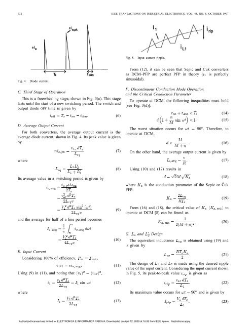
Fig. 4. Diode current.<br />
C. Third Stage of Operation<br />
This is a freewheeling stage, shown in Fig. 3(c). This stage<br />
lasts until the start of a new switching period. <strong>The</strong> switch <strong>and</strong><br />
output diode OFF time is given by<br />
D. Average Output Current<br />
For both converters, the average output current is the<br />
average diode current, shown in Fig. 4. Its peak value is given<br />
by<br />
where<br />
Its average value in a switching period is given by<br />
<strong>and</strong> the average for half of a line period becomes<br />
E. Input Current<br />
Considering 100% of efficiency, ,<br />
Using (9) in (11), <strong>and</strong> noting that ,<br />
where<br />
(6)<br />
(7)<br />
(8)<br />
(9)<br />
(10)<br />
(11)<br />
(12)<br />
(13)<br />
Fig. 5. Input current ripple.<br />
From (12), it can be seen that <strong>Sepic</strong> <strong>and</strong> Ćuk converters<br />
as DCM–PFP are perfect PFP in theory ( is perfectly<br />
sinusoidal).<br />
F. <strong>Discontinuous</strong> <strong>Conduction</strong> <strong>Mode</strong> Operation<br />
<strong>and</strong> the Critical <strong>Conduction</strong> Parameter<br />
To operate at DCM, the following inequalities must hold<br />
[see Fig. 3(d)]:<br />
(14)<br />
(15)<br />
<strong>The</strong> worst situation occurs for . <strong>The</strong>refore, to<br />
operate at DCM,<br />
On the other h<strong>and</strong>, the average output current is given by<br />
Using (10) <strong>and</strong> (17) results in<br />
(16)<br />
(17)<br />
(18)<br />
where is the conduction parameter of the <strong>Sepic</strong> or Ćuk<br />
PFP:<br />
(19)<br />
From (16) <strong>and</strong> (18), the critical value of to<br />
operate at DCM [8] can be found as<br />
(20)<br />
G. <strong>and</strong> Design<br />
<strong>The</strong> equivalent inductance<br />
is given by<br />
is obtained using (19) <strong>and</strong><br />
(21)<br />
<strong>The</strong> design of <strong>and</strong> is made using the desired ripple<br />
value of the input current. Considering the input current shown<br />
in Fig. 5, its peak-to-peak value is given as<br />
Its maximum value occurs for <strong>and</strong> is given by<br />
Authorized licensed use limited to: ELETTRONICA E INFORMATICA PADOVA. Downloaded on April 12, 2009 at 16:08 from IEEE Xplore. Restrictions apply.<br />
(22)<br />
(23)