The Discontinuous Conduction Mode Sepic and ´ Cuk Power
The Discontinuous Conduction Mode Sepic and ´ Cuk Power
The Discontinuous Conduction Mode Sepic and ´ Cuk Power

Create successful ePaper yourself
Turn your PDF publications into a flip-book with our unique Google optimized e-Paper software.
636 IEEE TRANSACTIONS ON INDUSTRIAL ELECTRONICS, VOL. 44, NO. 5, OCTOBER 1997<br />
(a) (b)<br />
(c) (d)<br />
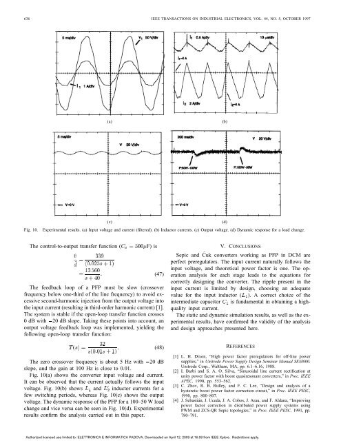
Fig. 10. Experimental results. (a) Input voltage <strong>and</strong> current (filtered). (b) Inductor currents. (c) Output voltage. (d) Dynamic response for a load change.<br />
<strong>The</strong> control-to-output transfer function ( F) is<br />
(47)<br />
<strong>The</strong> feedback loop of a PFP must be slow (crossover<br />
frequency below one-third of the line frequency) to avoid excessive<br />
second-harmonic injection from the output voltage into<br />
the input current (resulting in third-order harmonic current) [1].<br />
<strong>The</strong> system is stable if the open-loop transfer function crosses<br />
0 dB with 20 dB slope. Taking these points into account, an<br />
output voltage feedback loop was implemented, yielding the<br />
following open-loop transfer function:<br />
(48)<br />
<strong>The</strong> zero crossover frequency is about 5 Hz with 20 dB<br />
slope, <strong>and</strong> the gain at 100 Hz is close to 0.01.<br />
Fig. 10(a) shows the converter input voltage <strong>and</strong> current.<br />
It can be observed that the current actually follows the input<br />
voltage. Fig. 10(b) shows <strong>and</strong> inductor currents for a<br />
few switching periods, whereas Fig. 10(c) shows the output<br />
voltage. <strong>The</strong> dynamic response of the PFP for a 100–50 W load<br />
change <strong>and</strong> vice versa can be seen in Fig. 10(d). Experimental<br />
results confirm the analysis carried out in this paper.<br />
V. CONCLUSIONS<br />
<strong>Sepic</strong> <strong>and</strong> Ćuk converters working as PFP in DCM are<br />
perfect preregulators. <strong>The</strong> input current naturally follows the<br />
input voltage, <strong>and</strong> theoretical power factor is one. <strong>The</strong> operation<br />
analysis for each stage leads to the equations for<br />
correctly designing the converter. <strong>The</strong> ripple present in the<br />
input current is limited by design, choosing an adequate<br />
value for the input inductor ( ). A correct choice of the<br />
intermediate capacitor is fundamental in obtaining a highquality<br />
input current.<br />
<strong>The</strong> static <strong>and</strong> dynamic simulation results, as well as the experimental<br />
results, have confirmed the validity of the analysis<br />
<strong>and</strong> design approaches presented here.<br />
REFERENCES<br />
[1] L. H. Dixon, “High power factor preregulators for off-line power<br />
supplies,” in Unitrode <strong>Power</strong> Supply Design Seminar Manual SEM600,<br />
Unitrode Corp., Waltham, MA, pp. 6.1–6.16, 1988.<br />
[2] I. Barbi <strong>and</strong> S. A. O. Silva, “Sinusoidal line current rectification at<br />
unity power factor with boost quasiresonant converters,” in Proc. IEEE<br />
APEC, 1990, pp. 553–562.<br />
[3] C. Zhov, R. B. Ridley, <strong>and</strong> F. C. Lee, “Design <strong>and</strong> analysis of a<br />
hysteretic boost power factor correction circuit,” in Proc. IEEE PESC,<br />
1990, pp. 800–807.<br />
[4] J. Sebastián, J. Uceda, J. A. Cobos, J. Arau, <strong>and</strong> F. Aldana, “Improving<br />
power factor correction in distributed power supply systems using<br />
PWM <strong>and</strong> ZCS-QR <strong>Sepic</strong> topologies,” in Proc. IEEE PESC, 1991, pp.<br />
780–791.<br />
Authorized licensed use limited to: ELETTRONICA E INFORMATICA PADOVA. Downloaded on April 12, 2009 at 16:08 from IEEE Xplore. Restrictions apply.