Atlas Copco Air Motors
Atlas Copco Air Motors
Atlas Copco Air Motors

You also want an ePaper? Increase the reach of your titles
YUMPU automatically turns print PDFs into web optimized ePapers that Google loves.
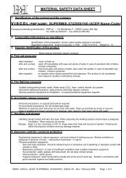
Shaft loading<br />
The permitted radial and axial shaft extension loadings are<br />
illustrated in Figure 2. These values have been calculated for<br />
shaft and bearing working lives of at least 1,000 hours at a<br />
speed that gives maximum output.<br />
Clockwise rotation – the position of these restrictors<br />
must be reversed.<br />
Reversing duty – restrictor (1) must be replaced by a<br />
second restrictor of type (2). The restrictor (1) must then be<br />
fitted into the inlet to the control valve.<br />
For further information refer to ‘Installation Examples’ on<br />
page 74.<br />
It is permissable to remove these restrictors to increase<br />
motor output. However, the motor should not be run faster<br />
than max allowed speed (see data table).<br />
Mounting<br />
Type LZL vane motors may be mounted in any position. To<br />
facilitate this, a flange is integrated into the motor casing and<br />
a foot mounting is available for each motor variant.<br />
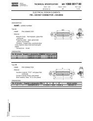
Connection<br />
Type LZL motors are supplied with internal restrictors in the<br />
connection ports. As illustrated in Figure 3, one is larger<br />
than the other.<br />
Fa<br />
Anti-Clockwise rotation – the smaller restrictor (N) (1) is<br />
fitted in the inlet port and the larger restrictor (2) in the outlet<br />
1200<br />
port (as shown).<br />
Hose dimensions<br />
Information on hose dimensions recommended for use with<br />
type LZL air motors is detailed in Table 2. These dimensions 800<br />
are valid for hose lengths up to 3 m. If lengths above that are<br />
used, choose a one size larger hose.<br />
600<br />
Fa<br />
(N)<br />
1200<br />
1000<br />
800<br />
600<br />
400<br />
200<br />
LZL 35<br />
LZL 25<br />
LZL 15<br />
LZL 05<br />
200<br />
400<br />
600<br />
A = 25 mm<br />
A = 25 mm<br />
A = 25 mm<br />
A = 20 mm<br />
800<br />
1000<br />
1200<br />
1000<br />
400<br />
200<br />
LZL 35<br />
LZL 25<br />
LZL 15<br />
LZL 05<br />
LZL 03<br />
200<br />
1400 1600 1800<br />
Connection<br />
thread<br />
(BSP)<br />
400<br />
2000<br />
600<br />
A = 25 mm<br />
A = 25 mm<br />
A = 25 mm<br />
A = 20 mm<br />
A = 20 mm<br />
800<br />
1000<br />
1200<br />
2200 2400 2600 2800<br />
3000<br />
Figure 3<br />
NON-REVERSIBLE DUTY REVERSIBLE DUTY<br />
Inlet hose<br />
diameter<br />
(mm)<br />
Exhaust<br />
hose<br />
diameter<br />
(mm)<br />
Inlet hose<br />
diameter<br />
(mm)<br />
Exhaust<br />
hose<br />
diameter<br />
(mm)<br />
Motor<br />
type<br />
LZL 03 3/8" 12.5 16 16 16<br />
LZL 05 1/2" 12.5 20.0 20.0 20.0<br />
LZL 15 3/4" 16.0 25.0 25.0 25.0<br />
LZL 25 1" 20.0 32.0 32.0 32.0<br />
LZL 35 1 1/4" 20.0 32.0 32.0 32.0<br />
Table 2<br />
1400 1600 1800<br />
Fr<br />
Figure 2<br />
AT L A S C O P C O A I R M O T O R S 5 1