Atlas Copco Air Motors
Atlas Copco Air Motors
Atlas Copco Air Motors

Create successful ePaper yourself
Turn your PDF publications into a flip-book with our unique Google optimized e-Paper software.
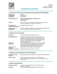
Methods of modifying motor<br />
output<br />
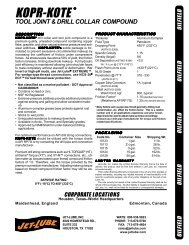
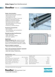
Throttling<br />
A throttle is usually fitted into the motor´s inlet hose, although<br />
it can also be fitted into the exhaust hose. When it is<br />
desirable to maintain a high starting torque but reduce running<br />
speed – throttling is the best method of modifying the<br />
motor´s output, Figure 5.<br />
Torque<br />
[Nm]<br />
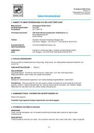
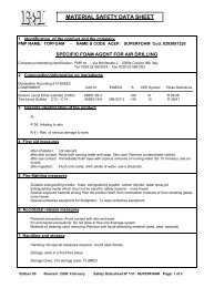
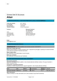
Pressure regulation<br />
When using a pressure regulator it is mostly fitted into the<br />
motor´s inlet hose. The use of pressure regulation is ideal<br />
when control of the stall torque is required and a high starting<br />
torque is not so important, Figure 6.<br />
Torque<br />
[%]<br />
100<br />
Par<br />
[Nm]<br />
Speed [r/min]<br />
Operating pressure<br />
7 bar<br />
6 bar<br />
5 bar<br />
4 bar<br />
3 bar<br />
100<br />
Speed [%]<br />
Using the catalogue<br />
Motor data, specification and performance<br />
curves<br />
Velocidad [r/min]<br />
Figure 5<br />
Figure 6<br />
For each <strong>Atlas</strong> <strong>Copco</strong> motor/gear unit combination the following<br />
information is presented in this catalogue.<br />
1. Tabular Data – Summary of main performance<br />
parameters.<br />
2.Dimensional drawings.<br />
3.Performance curves.<br />
Notes on performance data<br />
The performance data stated in this catalogue is valid for an<br />
air supply pressure of 6.3 bar (91 psi), gauge. <strong>Air</strong> consumption<br />
values are for free air delivery – (ie, the volume the consumed<br />
air would occupy if allowed to expand to atmospheric<br />
pressure).<br />
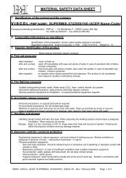
The direction of rotation for a motor is always stated looking<br />
from the back of the motor. Figure 7 illustrate clockwise rotation.<br />
Figure 7<br />
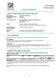
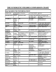
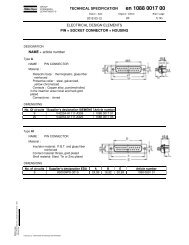
Understanding the performance curves<br />
The output of an air motor is most clearly seen from its<br />
performance curves Figure 8. For each motor/gear unit the<br />
power, torque and air consumption are shown as a function<br />
of speed.<br />
The diagrams shown apply to an inlet pressure of 6.3 bar, to<br />
calculate performance at other pressures refer to page 70 in<br />
this catalogue.<br />
Torque<br />
[Nm]<br />
Power<br />
[kW]<br />
Max<br />
output<br />
Torque<br />
at max<br />
output<br />
Motor selection<br />
Guidelines on motor selection are given on page 70 in this<br />
catalogue – Choosing Your Motor.<br />
Installation<br />
Power<br />
Torque<br />
<strong>Air</strong> cons.<br />
[l/s]<br />
<strong>Air</strong>. cons.<br />
Speed [r/min]<br />
Note. The starting torque<br />
produced by an air motor is<br />
variable and depends on vane<br />
position. These diagrams<br />
do not indicate the starting<br />
torque – this can be obtained<br />
from data tables, where the<br />
minimum value is shown.<br />
Figure 8<br />
General installation recommendations are given on page 72.<br />
Details specific to a motor are shown in the section relevant<br />
to that motor type.<br />
AT L A S C O P C O A I R M O T O R S 7