Atlas Copco Air Motors
Atlas Copco Air Motors
Atlas Copco Air Motors

You also want an ePaper? Increase the reach of your titles
YUMPU automatically turns print PDFs into web optimized ePapers that Google loves.
Choosing your<br />
motor<br />
The working point<br />
When selecting an air motor for a certain application, the first<br />
step is to establish what is called the “working point”. This is<br />
the point described by the desired operating speed for the<br />
motor and the torque required at that speed.<br />
The wide operating range of the air motor makes it probable<br />
that a number of motors could run with the same working<br />
point. However, as it is most efficient to run an air motor at<br />
the maximum output speed, the motor that produces maximum<br />
power nearest to the working point should be selected.<br />
The power required at the working point is calculated by:<br />
Power = π x M x n [W]<br />
30<br />
Where, M = Torque at working point (in Nm)<br />
n = Speed at working point (in r/min)<br />
Example:<br />
A non-reversible motor is required to run at 300 r/min and produce a<br />
torque of 10 Nm. Selection of correct motor size is as follows:<br />
Power required (W) = 3.14 x 10 x 300/30 = 314<br />
From Table 5 the correct size of non-reversible<br />
motor for this application is the LZB 33.<br />
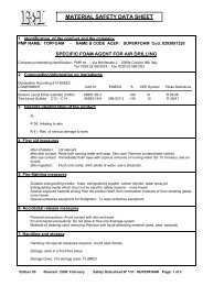
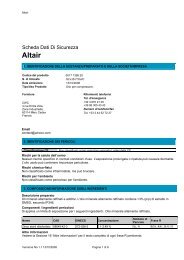
Once the motor size has been identified, simply look at the<br />
performance curves for each motor variant and select the<br />
one with max output nearest to the working point. For the<br />
above example this would be the LZB 33 A007.<br />
Power<br />
[kW]<br />
0.4<br />
0.3<br />
0.2<br />
0.1<br />
Torque<br />
[Nm]<br />
20<br />
16<br />
12<br />
8<br />
4<br />
200<br />
<strong>Air</strong> cons.<br />
[l/s]<br />
10<br />
8<br />
6<br />
4<br />
2<br />
Power<br />
[kW]<br />
Torque<br />
[Nm]<br />
400 600<br />
Speed<br />
800 [r/min]<br />
200<br />
0.4<br />
0.3<br />
0.2<br />
0.1<br />
24<br />
20<br />
16<br />
12<br />
8<br />
4<br />
Torque<br />
[Nm]<br />
Pressure regulation<br />
8<br />
M1 = desired torque<br />
6<br />
n1 = desired speed<br />
M 4<br />
2 = torque at maximum output<br />
n2 = speed at maximum output<br />
2<br />
LZB 33 A007 LZB 33 A005<br />
Figure 6<br />
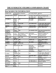
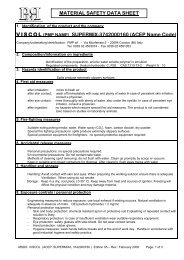
If necessary, one of the flow control methods can be used<br />
to modify the output of a motor to meet the working point<br />
exactly<br />
(Figure 7).<br />
Desired working point<br />
Torque with standard<br />
motor at 6.3 bar (91 psi)<br />
Torque with throttled<br />
motor<br />
Torque with pressure<br />
regulator<br />
Speed [r/min]<br />
Sometimes the motor operates at other supply pressures<br />
than 6.3 bar. In these cases the performance of a motor<br />
must be re-calculated to ensure the working point can be<br />
achieved.<br />
To calculate performance at supply pressures other than 6.3<br />
bar, multiply the data at 6.3 bar by the correction factors<br />
shown in Table 6.<br />
Correction factors<br />
<strong>Air</strong> Pressure<br />
<strong>Air</strong><br />
Consump-<br />
(bar) (psi) Output Speed Torque<br />
tion<br />
7 101 1.13 1.01 1.09 1.11<br />
6 87 0.94 0.99 0.95 0.96<br />
5 73 0.71 0.93 0.79 0.77<br />
4 58 0.51 0.85 0.63 0.61<br />
3 44 0.33 0.73 0.48 0.44<br />
Table 6<br />
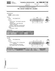
It is also easy to calculate the inlet pressure required to<br />
<strong>Air</strong> cons.<br />
achieve a desired working [l/s] point.<br />
Example:<br />
An LZB 22 A036 is required to run at 1155 r/min and produce 1.2 Nm;<br />
calculate the required inlet pressure to achieve this.<br />
For this motor at maximum output the torque is 1.5 Nm and the speed is<br />
10<br />
1650 r/min.<br />
Calculate the ratios M Speed<br />
1 /M2 and n<br />
400 600 [r/min]<br />
1 /n2 Therefore M1 /M2 = 0.8 and n1 /n2 = 0.7<br />
Apply these values to the diagram in figure 8 and read off<br />
the pressure at the intersection point.<br />
The required inlet pressure is 4.2 bar (61 psi)<br />
Figure 7<br />
Vane motors<br />
LZB 14 LZB 22 LZB 33/34 LZB 42 LZB 46 LZB 54 LZB 66 LZB 77 LZL 03 LZL 05 LZL 15 LZL 25 LZL 35<br />
Non reversible A A A A A A A A<br />
Reversible AR AR AR AR AR AR AR AR<br />
Output (kW)<br />
Table 5<br />
0.10 0.16 0.16 0.25 0.23 0.39 0.50 0.65 0.58 0.84 0.78 1.20 1.40 1.80 2.50 2.90 1.0 1.30 2.30 3.40 5.20<br />
Shows the power output for all <strong>Atlas</strong> <strong>Copco</strong> vane motors. The correct motor size is determined by selecting a motor with a power output above that<br />
required at the working point.<br />
7 0 AT L A S C O P C O A I R M O T O R S