chapter 3 - Bentham Science
chapter 3 - Bentham Science
chapter 3 - Bentham Science

Create successful ePaper yourself
Turn your PDF publications into a flip-book with our unique Google optimized e-Paper software.
Fault Analysis in Power Systems Applications of Spreadsheets in Education The Amazing Power of a Simple Tool 5<br />
4. Transmission lines are represented by their equivalent series reactances. Series resistances<br />
and shunt admittances are ignored.<br />
5. Synchronous machines are represented by constant-voltage sources behind subtransient reactances.<br />
Armature resistance, pole saliency, and saturation effects are ignored.<br />
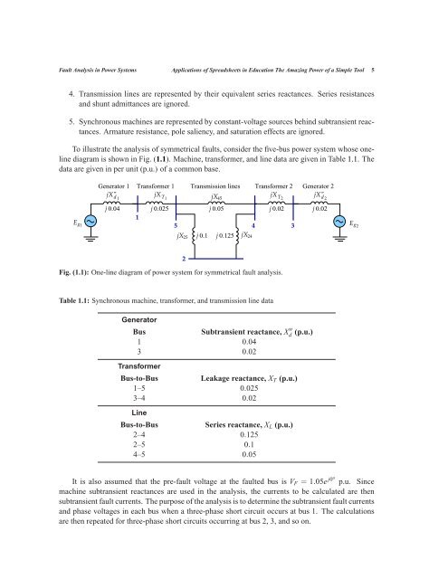
To illustrate the analysis of symmetrical faults, consider the five-bus power system whose oneline<br />
diagram is shown in Fig. (1.1). Machine, transformer, and line data are given in Table 1.1. The<br />
data are given in per unit (p.u.) of a common base.<br />
Eg1<br />
Generator 1 Transformer 1<br />
jX" d 1<br />
jXT1 j 0.04 j 0.025<br />
1<br />
jX25<br />
j 0.1<br />
jX45<br />
j 0.05<br />
5 4<br />
2<br />
Transmission lines<br />
j 0.125<br />
jX24<br />
Transformer 2 Generator 2<br />
jXT2 jX" d 2<br />
j 0.02<br />
Fig. (1.1): One-line diagram of power system for symmetrical fault analysis.<br />
Table 1.1: Synchronous machine, transformer, and transmission line data<br />
Generator<br />
Bus Subtransient reactance, X ′′<br />
d (p.u.)<br />
1 0.04<br />
3 0.02<br />
Transformer<br />
Bus-to-Bus Leakage reactance, XT (p.u.)<br />
1–5 0.025<br />
3–4 0.02<br />
Line<br />
Bus-to-Bus Series reactance, XL (p.u.)<br />
2–4 0.125<br />
2–5 0.1<br />
4–5 0.05<br />
It is also assumed that the pre-fault voltage at the faulted bus is VF = 1.05e j0o p.u. Since<br />
machine subtransient reactances are used in the analysis, the currents to be calculated are then<br />
subtransient fault currents. The purpose of the analysis is to determine the subtransient fault currents<br />
and phase voltages in each bus when a three-phase short circuit occurs at bus 1. The calculations<br />
are then repeated for three-phase short circuits occurring at bus 2, 3, and so on.<br />
3<br />
j 0.02<br />
Eg2