Download VERICUT 6.0 Flyer - CGTech
Download VERICUT 6.0 Flyer - CGTech
Download VERICUT 6.0 Flyer - CGTech

You also want an ePaper? Increase the reach of your titles
YUMPU automatically turns print PDFs into web optimized ePapers that Google loves.
<strong>VERICUT</strong> <strong>6.0</strong><br />
Streamlining Simulation<br />
Simulate and optimize the entire<br />
CNC machining process with<br />
<strong>VERICUT</strong> <strong>6.0</strong>! With <strong>VERICUT</strong>,<br />
your shop can produce better results<br />
while significantly reducing<br />
the time spent programming and<br />
machining.<br />
Multiple Setups in<br />
a Single Session<br />
<strong>VERICUT</strong> <strong>6.0</strong> allows you to view<br />
and configure multiple setups in<br />
one session using the new Project<br />
Tree. For each setup, you select<br />
the CNC machine configuration,<br />
attach the fixture and stock to the<br />
virtual machine, and select cutting<br />
tools and NC programs. You are<br />
then ready to simulate the entire<br />
set of machining operations in<br />
a single <strong>VERICUT</strong> session. The<br />
configuration steps described<br />
above can also be automatically<br />
configured from your CAD/CAM<br />
system using one of <strong>CGTech</strong>’s<br />
CAD/CAM interfaces. Menus for<br />
day-to-day project configuration<br />
are clearly separated from initial<br />
machine configuration menus,<br />
making it easy to setup daily<br />
simulation projects. All interfaces<br />
have been updated to support<br />
multiple setups. The coordinate<br />
systems defined in the CAD/<br />
CAM software are used to locate<br />
models for each setup.<br />
64-Bit<br />
Hardware<br />
Supported<br />
<strong>VERICUT</strong> <strong>6.0</strong> runs as a 64 bit<br />
application on Windows XP64.<br />
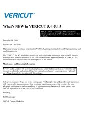
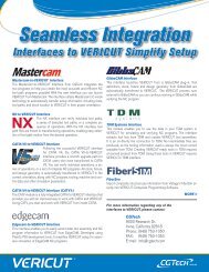
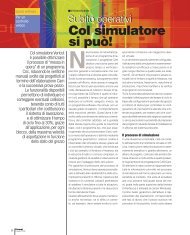
With the new Project Tree in <strong>VERICUT</strong> <strong>6.0</strong> (shown above),<br />
all NC process steps are organized in one place.<br />
Redesigned Tool Manager Speeds NC Program Optimization<br />
while New Tool Assembly Wizard Simplifies Tool Creation<br />
OptiPath ® , <strong>VERICUT</strong>’s NC program<br />
optimization module, is<br />
easier to implement thanks to<br />
a redesigned Tool Manager.<br />
OptiPath cutting data is now<br />
stored inside the Tool Manager.<br />
Not only does this simplify the<br />
implementation, but multiple<br />
tools can reference one OptiPath<br />
record. Creating new tools has<br />
also been simplified. The new tool<br />
assembly wizard allows you<br />
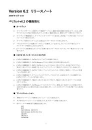
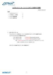
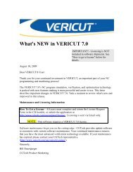
<strong>VERICUT</strong> <strong>6.0</strong><br />
supports multiple<br />
driven points per<br />
tool. Also, OptiPath<br />
cutting data is now<br />
stored inside the Tool<br />
Manager and the new<br />
tool assembly wizard<br />
makes creating new<br />
milling tools easier<br />
than ever.<br />
to create a new milling tool in<br />
one simple panel by answering<br />
a few questions. Alternatively, if<br />
a tool has already been created<br />
in another library, users can reference<br />
or copy the complete tool<br />
assembly, or only the cutter or<br />
holder portions. Users with large<br />
tool libraries will appreciate a<br />
new search feature that simplifies<br />
finding existing tools in both<br />
single and multiple tool libraries.<br />
Frequently used information and<br />
measurement panels can now be<br />
“docked” within the desktop.<br />
Model Export Enhancements<br />
Model Export creates CAD models<br />
from the <strong>VERICUT</strong> “in-process”<br />
cut model generated by simulating<br />
an NC program. In <strong>VERICUT</strong><br />
<strong>6.0</strong>, Model Export now outputs<br />
features where possible and also<br />
“synthetic features” when individual<br />
features are not possible or<br />
desirable (such as scallops created<br />
by a ball end mill). Trimming<br />
curves are now NURBS, resulting<br />
in smaller file sizes. Users can<br />
also now output native CATIA V5,<br />
CATIA V4, ACIS SAT, and STEP<br />
models with an optional CAD import/export<br />
module.<br />
<strong>CGTech</strong><br />
9000 Research Dr.<br />
Irvine, California 92618<br />
Phone: (949) 753-1050<br />
FAX: (949) 753-1053<br />
E-mail: info@cgtech.com<br />
.com
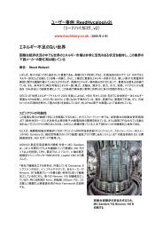
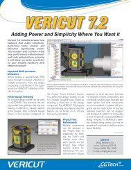
Create CNC Probe Programs & Inspection Sequences<br />
The CNC Machine Probing module has been enhanced to create CNC probe programs.<br />
<strong>VERICUT</strong> is an ideal place to create probing routines because of its in-pro-<br />
cess model which is not available anywhere else in the CNC manufacturing<br />
process. Using <strong>VERICUT</strong>’s simulated in-process feature geometry<br />
to create a CNC probe program makes on-machine in-process<br />
inspection a practical reality. In addition to CNC machine probe<br />
programming, <strong>VERICUT</strong> <strong>6.0</strong> allows the creation of inspection<br />
instruction documents in HTML or PDF format for use by<br />
machine operators or quality control staff.<br />
Minimum Cutter Height<br />
<strong>VERICUT</strong> <strong>6.0</strong> can automatically calculate the minimum<br />
cutter extension for all milling tools. This feature applies<br />
to the first two holders in the tool assembly, such as an<br />
extension and a holder body. At the end of the simulation<br />
you will be notified of any tool assembly changes<br />
and prompted to save the modified tool library.<br />
2. Features are<br />
selected<br />
Tool, Spindle, Cutter<br />
and Holder Enhancements<br />
<strong>VERICUT</strong> <strong>6.0</strong> detects incorrect tool & spindle cutting<br />
conditions before the NC program is run on the machine. For<br />
example, an error is reported during a turning operation if the cutter<br />
enters material and:<br />
• The turning insert is not properly centered on the material.<br />
• The drill is not on the turning center-line for the drilling<br />
operation.<br />
• The part is spinning in the wrong direction for the selected tool.<br />
A milling tool will likewise report errors when:<br />
• The milling spindle is not spinning.<br />
• The milling spindle is spinning in the wrong direction.<br />
A probe tool will also report collisions or errors when:<br />
• The probe tip contacts anything when not in probing mode.<br />
• The probe’s stem or holder contacts anything, whether probing<br />
mode is active or not.<br />
• The spindle is turned on, or is spinning above a maximum<br />
allowable speed for a probe.<br />
Holder collisions in <strong>VERICUT</strong> <strong>6.0</strong> no longer remove material. All collisions<br />
create a volume that is available for later analysis in order to<br />
correct the NC program or process problem.<br />
Simulate Machines with Multiple Synchronized<br />
Tools, Spindles and Auxiliary Attachments<br />
<strong>VERICUT</strong> <strong>6.0</strong> now offers the capability to synchronize up to 32 machine<br />
“channels” or machines with multiple synchronized CNC controls.<br />
<strong>VERICUT</strong>’s virtual machine is organized into multiple sub-systems that<br />
are all synchronized to run<br />
together seamlessly. Three<br />
simultaneous machining<br />
operations on a Citizen machine<br />
with a Mitsubishi M32<br />
control? Nakamura machines<br />
with Fanuc controls<br />
and four complex simultaneous<br />
operations? <strong>VERICUT</strong><br />
simulates it all.<br />
1. The part<br />
is cut<br />
5. Probe motions<br />
are simulated prior<br />
to being sent to<br />
CNC machine<br />
4. G-code<br />
output<br />
3. Parameters<br />
are set (postprocessor,<br />
cycle<br />
types, tolerances,<br />
etc.)<br />
Inspection and Measurement Enhancements<br />
X-Caliper allows you to measure thickness, volume, depth, gaps, distances,<br />
angels, hole diameters, corner radii, scallop heights, etc. It is<br />
improved in <strong>VERICUT</strong> <strong>6.0</strong> to optionally highlight features, such as all<br />
planes on the<br />
same level. You<br />
can also now view<br />
and measure all<br />
tool collisions,<br />
even after subsequent<br />
machining<br />
operations have<br />
removed them<br />
from the screen.<br />
Colors<br />
Up to 128 cutting colors can now be chosen. Additionally, the workpiece<br />
can be colored according to feed rates or tool color or tool sequence.<br />
Any color display can be chosen without re-running the simulation.<br />
Constant Gouge Check Redesigned<br />
<strong>VERICUT</strong>’s constant gouge check is now much faster, simpler and<br />
more accurate than ever before. It also works on a single pass and<br />
requires less memory.<br />
© <strong>CGTech</strong> 2006. All rights reserved.<br />
<strong>CGTech</strong>, OptiPath, and <strong>VERICUT</strong> are registered trademarks of <strong>CGTech</strong>. AUTO-DIFF, X-Caliper, PolyFix, CATV, and FastMill<br />
are trademarks of <strong>CGTech</strong>. All other trademarks are property of their respective owners. 5/06