Final Report - Claymore - Grand Valley State University
Final Report - Claymore - Grand Valley State University
Final Report - Claymore - Grand Valley State University

You also want an ePaper? Increase the reach of your titles
YUMPU automatically turns print PDFs into web optimized ePapers that Google loves.
<strong>Grand</strong> <strong>Valley</strong> <strong>State</strong> <strong>University</strong><br />
Padnos School of Engineering<br />
Target Acquisition and Firing System Design Project<br />
EGR 345 Dynamic Systems Modeling and Control<br />
Instructor: Dr. Jack<br />
Team 9 – “Young Gunners”<br />
Brian Coleman<br />
Steve Johnson<br />
Coty Lindell<br />
Bryan Masselink<br />
Haley Nghiem<br />
December 7, 2005
Executive Summary<br />
The objective of this design project was to develop a device to read a signal,<br />
locate a target, and fire a practice golf ball through the target autonomously in the least<br />
amount of time possible. An ATMega32 microcontroller and L298P H-bridge driver<br />
were used to control the device. Cost, weight, and size constraints were put under<br />
consideration.<br />
A stationary device with a rotating turret and launch mechanism was the optimal<br />
design choice upon consideration of the design parameters. The launch mechanism was a<br />
directed air nozzle contained within a 9 inch by 1.5 I.D. low-pressure PVC pipe. The<br />
positioning of the launch mechanism was controlled by a high-torque stepper motor. The<br />
stepper motor was fastened to an aluminum coupler, which was fastened to the launching<br />
mechanism. The balls were fed to the launching mechanism using a gravity fed, helical<br />
track wire hopper. The ATMega32 microcontroller was utilized to receive 5V inputs<br />
from an external source. When a signal was received, the stepper motor aligned the<br />
barrel with one of four targets and launched a practice golf to disable the target.<br />
Testing was executed to determine how the device would perform in the final<br />
competition. The test results revealed that air provided an adequate force to shoot the<br />
balls at the targets. Furthermore, the stepper motor provided accurate positioning of the<br />
barrel at an acceptable rate.<br />
1
Table of Contents<br />
1. Design Description......................................................................................................... 3<br />
1.1 Design Specifications................................................................................................ 3<br />
1.2 Mechanical Design.................................................................................................... 3<br />
1.2.1 Design Summary ................................................................................................ 3<br />
1.2.2. Mass and Budget of Materials .......................................................................... 4<br />
1.3 Software Design........................................................................................................ 5<br />
1.3.1 System Architecture ........................................................................................... 5<br />
1.3.2 Control System Block Diagram ......................................................................... 6<br />
1.4 Electrical Design....................................................................................................... 7<br />
2. Free Body diagram and Differential Equations .............................................................. 8<br />
2.1 Panning Angle Calculation ....................................................................................... 8<br />
2.1.1 Differential Equations for Stepper Motor.......................................................... 8<br />
2.1.2 Scilab Calculation for Panning Motor Selection.............................................. 9<br />
2.2 Ball Characteristic Calculations.............................................................................. 11<br />
2.2.1 Ball Velocity Before Launch ............................................................................ 11<br />
2.2.2 Projectile Motion Derivation........................................................................... 13<br />
2.2.3 Derivation for Individual Target Distance and Angle..................................... 15<br />
3. Test Results.................................................................................................................. 16<br />
3.1 Scilab Simulation Results ....................................................................................... 16<br />
3.2 Estimated Design Score .......................................................................................... 17<br />
4. Conclusions.................................................................................................................. 17<br />
5. Recommendations......................................................................................................... 18<br />
6. Digital Picture ............................................................................................................... 18<br />
7. Appendices................................................................................................................... 19<br />
7.1 Pro-E Drawings....................................................................................................... 19<br />
7.1.1 Exploded Assembly View with BOM............................................................... 19<br />
7.1.2 Orthographic Prints......................................................................................... 21<br />
7.1.3 Pro-E drawings................................................................................................ 22<br />
7.2 Gantt Chart.............................................................................................................. 30<br />
7.3 C Code .................................................................................................................... 31<br />
7.4 Scilab Code ............................................................................................................. 38<br />
2
1. Design Description<br />
1.1 Design Specifications<br />
The target acquisition and firing system device must contain all electrical<br />
and mechanical components except for the supplied power sources. The largest<br />
dimension of the design must be less than 12 inches, but smaller designs will<br />
receive more points. The device must have a mass less than 3 kg excluding any<br />
external power sources. The device may be powered by an external AC/DC<br />
voltage device or a pneumatic line or both. The equipment costs should be<br />
minimized, with a goal of $200 or less. The device must shoot practice golf balls<br />
approximately 1.5 inches in diameter at randomly activated targets 6 feet away.<br />
An electrical line will provide a 5 volt signal to the ATMega32 microcontroller.<br />
A different signal is provided for each of the four targets. The overall score of the<br />
design will depend on the number of targets hit in 2 minutes, total cost, largest<br />
dimension, build quality, theory quality, and mass of the device.<br />
1.2 Mechanical Design<br />
1.2.1 Design Summary<br />
The assembled drawing, shown in Figure 1, displays the major<br />
components of the target acquisition and firing device. The base of the machine<br />
was made of black polycarbonate, which was lightweight with high machinability.<br />
Four threaded rod supports were placed in the four corners of the base plate. The<br />
pan angle was controlled by a stepper motor. The PVC pipe firing mechanism was<br />
attached to the top of the stepper motor via a coupler and mounting bracket, and<br />
was approximately nine inches long by 1.5 inches I.D.. Since the stepper motor<br />
was mounted on the bottom of the base, the ATMega32 and the controller board<br />
were attached to the back of the base with two bolts for easy connections. A steel,<br />
sheet metal bracket, attached to the back of the barrel, was used to mount the air<br />
nozzle used to fire the balls. The steel bracket was designed to the increase<br />
airflow into the barrel. Thus, providing a larger force to the ball. When air<br />
3
pressure was applied, the flap rotated approximately 90º, preventing multiple balls<br />
from entering the barrel.<br />
Figure 1: Assembled view of the fire mechanism<br />
Appendix 7.1.1 shows the assembly exploded view of the mechanism,<br />
appendix 7.1.2 includes the orthographic prints of the machined part and appendix<br />
7.1.3 shows the pro-E drawings for all components used in the production of the<br />
device.<br />
1.2.2. Mass and Budget of Materials<br />
The total budget of the device was not exceed $200. A budget inventory<br />
was used to monitor the overall budget of the device. The mass of the device was<br />
a factor in the overall design score. The total mass of the device excluding<br />
external power sources must not exceed 3kg. The mass and budget of materials,<br />
shown in Table 1, were updated on a regular basis. Table 1 includes the unit price<br />
and mass for each item and where each item was purchased. The total money<br />
4
spent was $97.96 and the total mass of the machine was 995 grams. All receipts<br />
for purchased components are shown in Appendix 7.6.<br />
Table 1: Mass and Budget Inventory<br />
Quantity Unit<br />
Part Total<br />
Description<br />
used Price Source of Unit Price Mass(g) Mass(g)<br />
17Y series High Torque step<br />
Anaheim automation<br />
motor 1 $22.00 receipt 364 364<br />
Machined Polycarbonate plate 1 $1.97 Mcmaster/carr pg.3314 55 55<br />
(1) bottle Super Glue 1 $3.65 GVSU Book Store 0.01 0.01<br />
(2) packs of wiffle balls 2 $4.95 Target 0 0<br />
assorted hardware 1 $10.62 Godwin's hardware 20 46.49<br />
(1) ATMega circuit board 1 $30.00 GVSU 35 35<br />
2 feet, 1.5' diameter PVC pipe 1 $1.58 Menards 50 50<br />
Surface savers 1 $1.49 Godwin's hardware 5 20<br />
(8) U Joint 8 $0.29 Godwin's hardware 5 40<br />
(4) 1' Threaded rod 4 $1.29 Godwin's hardware 30 120<br />
1 ", 3/4" diameter aluminum rod 1 $0.59 Mcmaster/carr pp.3368 30 30<br />
1" Aluminum C channel 1 $0.52 Mcmaster/carr pp.3367 15 15<br />
1/2, 1 cubic foot sheet metal 1 $1.30 Mcmaster/carr pp.3379 10 10<br />
Motor controlled board with wires 1 $15.00 GVSU 85 85<br />
Air fitting 1 $1.47 Mcmaster/carr pp.238 20 20<br />
Hopper wire (11') 1 $1.89 Godwin's hardware 9.5 104.5<br />
Total Machine mass(g): 985<br />
Total Machine cost ($): $98.60<br />
1.3 Software Design<br />
1.3.1 System Architecture<br />
The system architecture of the device is shown in Figure 2. An<br />
ATMega32 microcontroller combined with an L298P H-bridge driver was used to<br />
control the air pulse and panning motor. The C program was written to control<br />
the ATMega32, and L298P is located in Appendix 7.3. The stepper motor was<br />
used to rotate the launching mechanism.<br />
5
ATMega32<br />
1 2 3 4<br />
Target Lines<br />
PWM<br />
A0 A1 A2 A3<br />
Figure 2: System Architecture<br />
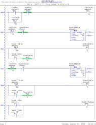
1.3.2 Control System Block Diagram<br />
The control system block diagram was developed to control the target<br />
acquisition and firing device as shown in Figure 3. When a target was activated,<br />
the controller input port received a digital-high signal. When a target (1, 2, 3 or<br />
4) was activated, a signal was sent to an input pin A0, A1, A2, or A3,<br />
respectively. The C program, shown in Appendix 7.3, commanded the stepper<br />
motor to turn to the desired target and deliver an air pulse to fire the ball. The<br />
software utilized an interrupt sequence to monitor the status of each target. The<br />
device launched balls until the target was deactivated. The sequence continues<br />
upon activation of the next target.<br />
Ci<br />
Air Valve<br />
H-bridge Vs Stepper<br />
Motor<br />
Pan<br />
Angle<br />
Air Valve<br />
θp<br />
Launch<br />
Mechanism<br />
Figure 3: System block diagram<br />
6<br />
w<br />
Launch<br />
Mechanism
Where,<br />
Ci = Target input signal<br />
θ = Panning Angle<br />
p<br />
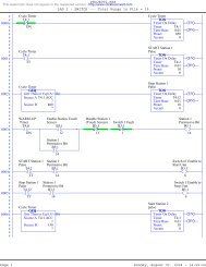
1.4 Electrical Design<br />
The electrical schematic of the device is shown in Figure 4. The electrical<br />
schematic includes the ATMega32 microcontroller, a L298P H-bridge push-pull<br />
four channel<br />
driver chip, and a 4 volt power supply. Four 1 KΩ resistors were<br />
used to reduce noise from the stepper motor.<br />
Figure 4: Electrical Schematic<br />
7
2. Free Body diagram and Differential Equations<br />
The calculations shown in subsequent sections was used to determine the required<br />
launch angle torque and launch speed needed to fire the ball the required distance. This<br />
calculation was helpful in the selection process of motors.<br />
2.1 Panning Angle Calculation<br />
2.1.1 Differential Equations for Stepper Motor<br />
τ Motor<br />
N<br />
FNR θ<br />
Figure 5: FBD for the Turn Table<br />
where, N= normal force (The hopper weight)<br />
W(hopper) = weight of the hopper and its configurations<br />
* *<br />
J θ = mass moment of inertia<br />
The differential equation for the launching angle from Figure 2.1 is<br />
* *<br />
∑ M : τ Motor − FNR = J θ .<br />
*<br />
Put (2.1) into state equation, let θ = ω<br />
ω *<br />
= τ<br />
Motor −<br />
J<br />
W(hopper)<br />
FNR<br />
8<br />
* *<br />
J θ<br />
(2.1)<br />
, (2.2)
where, ω = angular velocity of the launcher motor, τ = torque motor give, J =<br />
mass moment. The state equations above allow us to find the angular velocity the<br />
motor gives. Once angular velocity is found, time is found by<br />
dθ<br />
ω = . (2.3)<br />
dt<br />
Integrate (2.3), and solve for t = time<br />
t = θ / ω<br />
(2.4)<br />
2.1.2<br />
Scilab Calculation for Panning Motor Selection<br />
Figure 2.2: The torque and inertia in a basic motor model<br />
The first-order differential equation can developed from motor properties using<br />
some basic measurements.<br />
Tm = KI<br />
(2.6)<br />
Tm<br />
I = ( 2 .7)<br />
K<br />
where, T = motor torque, K= constant, and I = current. Then consider the<br />
m<br />
power in motor,<br />
P m +<br />
= V I = Tω<br />
KIω<br />
(2.8)<br />
V m = Kω<br />
(2.9)<br />
V m<br />
where, = voltage supply to motor, and P = power. The dynamics of the<br />
rotating masses can be found by summing moments,<br />
9
∑ ⎟ ⎞ ⎛ d<br />
M = Tm<br />
− TF<br />
= J⎜<br />
ω<br />
(2.10)<br />
⎝ dt ⎠<br />
⎛ d ⎞<br />
T m = J⎜<br />
⎟ω<br />
+ TF<br />
(2.11)<br />
⎝ dt ⎠<br />
where, J= motor rotor, T = frictional torque, and w= motor speed. The current-<br />
F<br />
voltage relationship for the left hand side of the equation can be written and<br />
manipulated<br />
to relate voltage and angular velocity.<br />
V Vm<br />
I = (2.12)<br />
R<br />
s −<br />
Tm Vs<br />
− Kω<br />
=<br />
K R<br />
⎛<br />
d<br />
dt<br />
⎞<br />
⎟ω<br />
+ T<br />
⎠<br />
K<br />
J⎜ F<br />
⎝<br />
(2.13)<br />
Vs<br />
− Kω<br />
= (2.14)<br />
R<br />
2<br />
⎛ d ⎞ ⎛ K ⎞ ⎛ K ⎞ TF<br />
⎜ ⎟ω<br />
+ ω = Vs<br />
⎜ ⎟ +<br />
dt ⎜<br />
JR ⎟<br />
⎝ ⎠ ⎝ ⎠ ⎝ JR ⎠ J<br />
From section 2.1,<br />
T F = F*N*R. The coefficients for the differential equation<br />
(2.15) can be found for the motor in a dynamic case using steady state<br />
velocities. At steady state (2.15) becomes<br />
2 ⎛ K ⎞ ⎛ K<br />
ω ⎜<br />
⎟ = Vs<br />
⎜<br />
⎝ JR ⎠ ⎝ JR<br />
K<br />
V<br />
ω<br />
= .<br />
s<br />
⎞<br />
⎟<br />
⎠<br />
Then J can be found because<br />
K 2<br />
(2.15)<br />
(2.16)<br />
(2.17)<br />
τ =<br />
(2.18)<br />
JR<br />
10
2<br />
K<br />
J =<br />
τR<br />
(2.19)<br />
where, τ =time constant.<br />
Time constant can be found by using 63% of steady<br />
value from voltage vs time curve. The static torque value can be found using the<br />
deadband limits,<br />
ω = 0;<br />
T < T<br />
F<br />
T ≠ ; T < 0 ω<br />
2.2 Ball Characteristic Calculations<br />
F<br />
S<br />
K<br />
2.2.1 Ball<br />
Velocity Before Launch<br />
Figure 6 shows the pathway of the ball in hopper<br />
feeder (slider), the arrow<br />
indicates the direction of the ball.<br />
Figure 6: Feeder pathway<br />
To calculate the velocity from the top ( V t ) of feeder to the bottom ( Vb<br />
), principle<br />
of work and energy<br />
is used,<br />
w<br />
here, ( t b)<br />
Start<br />
W +<br />
( t→b ) = W(<br />
t→b<br />
) conservative<br />
W(<br />
t→b<br />
) non−conservative<br />
, (2.20)<br />
W → = work from top to bottom of feeder . Conservative work includes<br />
all work and energy that are path independent,<br />
Finish<br />
W = V + T,<br />
(2.21)<br />
11
where, V= potential energy, and T= kinetic energy. Work due to gravity (potential<br />
energy) occurs when the ball is dropped through a feeder. Work due to gravity is<br />
defined as<br />
Vg = mgh , (2.22)<br />
where V = work due to gravity, m = mass of an object, g = gravity, h= distance<br />
from which the object is dropped, Figure 2.3. The ball is moving with kinetic<br />
energy,<br />
g<br />
1 2<br />
mv<br />
T = , ( 2.23)<br />
2<br />
where, m = mass of an object, and v = object velocity. Non-conservative work is<br />
work due to friction,<br />
W = Fds , (2.24)<br />
friction<br />
sb<br />
where W friction = non conservative work due to friction,<br />
F= friction force as a<br />
function of time, ds = change in distance the ball is dropped, S t = initial position<br />
(2.24), then substitute them in (2.20),<br />
∫<br />
st<br />
of the ball, and Sb<br />
=final position of the ball. Combine (2.21), (2.22), (2.23) and<br />
1<br />
2<br />
mv<br />
2<br />
t<br />
s<br />
b<br />
1 2<br />
+ mght<br />
+ ∫ Fds = mvb<br />
+ mghb<br />
, (2.25)<br />
2<br />
st<br />
where, vt<br />
= initial velocity at top of feeder, v b = velocity of ball at the bottom of<br />
feeder, h = the height at the top of feeder, and h = the height at the bottom of<br />
t b<br />
feeder. Figure<br />
2.4 shows the free body diagram of the ball from feeder. The ball<br />
starts at rest, with the height of h, as shown in Figure 2.3.<br />
12
Figure 7: Free body diagram of the ball<br />
Equation (2.25) is used to calculate the speed of the ball at the bottom of feeder<br />
Based on the free body diagram, Figure 7,<br />
mgy<br />
t<br />
sb<br />
1<br />
+ ∫ FNds =<br />
2<br />
st<br />
mv<br />
where, F = force of friction, and N = normal force of ball.<br />
2.2.2 Projectile Motion Derivation<br />
2<br />
b<br />
+ mgy , (2.26)<br />
Figure 8: Projectile motion from launch position to targets.<br />
Start out with the definition of a vector r in space,<br />
r ( t)<br />
= x(<br />
t)<br />
i + y(<br />
t)<br />
j , (2.27)<br />
whe re r (t)<br />
= vector in space, x ( t)<br />
i = position of time in x direction, and y ( t)<br />
j =<br />
position of time in y direction. The acceleration in x direction is 0 ( a = 0 ),<br />
therefore, the function of x direction with respect<br />
to time is defined,<br />
13<br />
b<br />
x
x i 0x<br />
( t)<br />
= x + V t , ( 2.28)<br />
where, x(t)= position in x direction with respect to time, x = initial position,<br />
V0x = initial velocity of the ball in x direction, and t = time. Whereas, acceleration<br />
for the y direction is the gravity (<br />
with respect to time is defined as,<br />
1<br />
2<br />
a y<br />
i<br />
= −g<br />
), therefore, the function of y direction<br />
2<br />
y( t)<br />
= yi<br />
+ V0<br />
yt<br />
− gt , (2.29)<br />
where, y(t) = position in y direction with respect to time, = initial position in y<br />
V 0 = initial velocity in the y direction, g = gravity, and t =<br />
direction, y<br />
time. From<br />
Figure 8, assumed initial position is 0, ( x = y = 0 ), and<br />
0<br />
0<br />
V x = V cosθ<br />
, (2.30)<br />
0<br />
0<br />
V = V sinθ<br />
, (2.31)<br />
0 y<br />
where, V 0 = initial velocity, and<br />
0<br />
(2.30), (2.31) into (2.28) and (2.29) respectively to get<br />
and<br />
Solve (2.32) for t,<br />
θ = the angle of launcher. Substitute value<br />
into<br />
x( t)<br />
= V0<br />
cosθ<br />
( t)<br />
, (2.32)<br />
1<br />
y( t)<br />
− gt<br />
2<br />
2<br />
= V0<br />
sinθ<br />
( t)<br />
(2.33)<br />
x<br />
t = (2.34)<br />
V cosθ<br />
0<br />
then substitute (2.34) back to (2.33),<br />
14<br />
y i
ut<br />
2<br />
x 1 ⎛ x ⎞<br />
y ( x)<br />
= V sinθ<br />
− ⎜ ⎟<br />
0<br />
g<br />
⎜ ⎟<br />
(2.35)<br />
2 2<br />
V0<br />
cosθ 2 ⎝V0<br />
cos θ ⎠<br />
cos<br />
1 2<br />
2<br />
θ<br />
Combine (2.35) and (2.36)<br />
to get<br />
(<br />
= 1 + tan ( θ )<br />
(2.36)<br />
)<br />
2 ( 1 tan θ )<br />
2<br />
gx<br />
y ( x)<br />
= x tanθ<br />
− +<br />
(2.37)<br />
2<br />
2V<br />
If y(x) is z, then solve for V0<br />
from (2.37);<br />
V<br />
0<br />
=<br />
0<br />
2 ( 1+<br />
tan ( ) )<br />
2<br />
gx θ<br />
(2.38)<br />
2(<br />
x tan( θ ) − z<br />
Equation (2.38) is used to find the desired initi al velocity base d on position<br />
of<br />
each target.<br />
2.2.3 Derivation for Individual Target Distance and Angle<br />
Figure 9: Launcher Position.<br />
The triangle above has an angle ofγ . The<br />
distance from the launcher to the<br />
midpoint of the target is the adjacent<br />
side of the triangle, “a”. The distance<br />
between the midpoint to a specific target is the opposite side of the triangle, “o”.<br />
From trigonometry, hypotenuse (“h” or the distance from launcher to a specific<br />
target) of the triangle can be found by using Pythagorean theorems,<br />
15
2 2 2<br />
h = a + o , ( 2.39)<br />
where, h= hypotenuse, a=adjacent, and o=opposite. Solve for h from (2.39),<br />
2 2<br />
h = a + o . (2.40)<br />
The angle can be found be using the tangent equation,<br />
o<br />
tan γ = .<br />
a<br />
Then solve for γ from (2.41),<br />
3. Test Results<br />
(2.41)<br />
−1⎛<br />
o ⎞<br />
γ = tan ⎜ ⎟ . (2.42)<br />
⎝ a ⎠<br />
3.1 Scilab Simulation Results<br />
A Scilab program was used to simulate the motion of the panning motor.<br />
The Scilab results are shown below in Figure 3.1. Figure 3.1 shows the position<br />
and angular speed of the panning motor with respect to time. Scilab program is<br />
shown in Appendix 7.4.<br />
Figure 10: Scilab Simulation Results<br />
16
3.2 Estimated Design Score<br />
The design<br />
score depends on the cost, mass, build quality, technical<br />
quality, and number<br />
of targets hit. The estimated contest score is shown in Table<br />
2. The following equation was<br />
used to asses the overall score for the design.<br />
Score = H<br />
Where,<br />
−2<br />
4)<br />
H = targets hit in 2 minutes<br />
C = total cost of<br />
( 10)<br />
parts<br />
L = largest dimensions<br />
(<br />
c<br />
80<br />
−B<br />
( 10)<br />
(inches)<br />
B = build quality (1 = best, 0 = worst)<br />
T = Technical quality (1 = best, 0 = worst)<br />
M = mass of machine (Kg)<br />
−T<br />
( 2)<br />
L<br />
( )<br />
3<br />
M<br />
Table 2: Estimated contest score<br />
H 143<br />
C 98.6<br />
L 12<br />
B 1<br />
T 1<br />
M 0.985<br />
Estimated Score<br />
4<br />
0.0000409205101<br />
4. Conclusions<br />
The machine that was designed and built for the purpose of target acquisition and<br />
elimination,<br />
performed as expected. When a target became active the stepper quickly<br />
moved the barrel into position and a ball was fired at the target. Through the design,<br />
build,<br />
and implementation of this machine, certain conclusions were arrived upon.<br />
17
1. The flap in front of the nozzle was sufficient at providing the ball with an<br />
initial acceleration and holding the next ball back.<br />
2. Mass was the most important factor in this project. By using light-weight<br />
components for the base and hopper, the mass of the device was under a<br />
kilogram causing a drastic effect on the score.<br />
3. Launch velocity increased as the airflow through the barrel increased.<br />
5. Recommendations<br />
After the performance the device was analyzed through testing and competition.<br />
The following are recommendations to improve the function of the mechanism:<br />
1. The inside diameter of the barrel should be decreased to improve the<br />
accuracy of the firing mechanism.<br />
2. A method<br />
to ensure that the stepper motor is consistently starting at the<br />
3. Eliminate all loose connections by soldering wires directly onto the L298P<br />
6. Digital<br />
Picture<br />
same position should be implemented.<br />
motor driver.<br />
Figure 11: Digital Photo of final Machine<br />
18
7. Appendices<br />
7.1 Pro-E Drawings<br />
7.1.1 Exploded Assembly View with BOM<br />
19
7.1.2 Orthographic Prints<br />
21
7.1.3 Pro-E drawings<br />
Figure 12: Machined base<br />
Figure 14: Stepper motor<br />
22
Figure 13: Barrel<br />
Figure 15: Air nozzle bracket<br />
23
Figure 16: Air fitting<br />
Figure 17: Barrel bracket<br />
24
Figure 18: Ball stopper flap<br />
Figure 19: Ball stopper flap hinge<br />
25
Figure 20: L_bracket (connect the barrel and ball stopper)<br />
Figure 21: Stepper motor shaft<br />
26
Figure 22: Rubber foot<br />
Figure 23: Helical hopper (one of two wires)<br />
27
Figure 24: Ball stopper<br />
Figure 25: Supporting rod<br />
28
Figure 26: Hopper U-joint<br />
Figure 27: Hopper bar<br />
Figure 28: Hopper slider<br />
29
7.2 Gantt Chart<br />
30
7.3 C Code<br />
//Author: Brian Coleman<br />
//Class: EGR 345<br />
//Date: 11/29/05<br />
//Include files<br />
#include<br />
#include <br />
#include <br />
#include "sio.c"<br />
//Function prototypes<br />
void CLK_setup(void);<br />
void IO_setup(void);<br />
void IO_update(void);<br />
void move_step(int dir, int step_delay);<br />
void write_step(int step);<br />
int check_targets(void);<br />
void delay(int ticks);<br />
void stop(void);<br />
//Global Constants<br />
#define UP 1<br />
#define DOWN 0<br />
#define HIGH 1<br />
#define LOW 0<br />
#define Start 0 //Initial target<br />
#define TARGET_1 -9 //Left-most target<br />
#define TARGET_2 -4 //Inner-left target<br />
#define TARGET_3 1 //Inner-right target<br />
#define TARGET_4 6 //Right-most target<br />
# define NUM_INTERRUPTS 10 //Number of interrupts per sec<br />
# define DELAY_TIME 25 //1 is the maximum speed<br />
#define FIRE_DELAY 200 //Air release time<br />
//Variables<br />
int<br />
steps[] = {1, 2, 4, 8};<br />
int<br />
position = 0;<br />
int last_target = 0;<br />
31
int current_target = 0;<br />
int destination = 0;<br />
int current_step =<br />
int i;<br />
-1;<br />
unsigned int CNT_timer1;<br />
//The delay time<br />
volatile unsigned int CLK_ticks<br />
= 0; //The current number of ms since<br />
last increment of CLK_seconds<br />
volatile unsigned<br />
since<br />
start<br />
int CLK_seconds = 0; //The current number of seconds<br />
/*-------------------------------<br />
Interrupt Stuff ---------------------<br />
----------*/<br />
SIGNAL(SIG_OVERFLOW1) / /The interrupt calls this function<br />
{<br />
CLK_ticks += (NUM_INTERRUPTS*10);<br />
if(CLK_ticks >= 1000)<br />
{<br />
beginning<br />
}<br />
}<br />
CLK_ticks -= 1000;<br />
CLK_seconds++;<br />
//Counts the number of seconds from the<br />
IO_update();<br />
TCNT1 = CNT_timer1;<br />
void CLK_setup(void) //Starts the interrupt service<br />
routine<br />
{<br />
TCCR1A = (0
}<br />
CNT_timer1 = 0xFFFF - 80;<br />
TCNT1 = CNT_timer1;<br />
//Start at the right point<br />
TIFR<br />
&= ~(1
}<br />
destination = current_target - position;<br />
if(destination > 0)<br />
{<br />
}<br />
{<br />
}<br />
{<br />
}<br />
for(i = 0; i < destination; i++)<br />
delay(250);<br />
delay(250);<br />
move_step(UP,<br />
DELAY_TIME);<br />
PORTB |= 0x20; //Set PB5<br />
delay(FIRE_DELAY);<br />
PORTB &= ~0x20; //Clear PB5<br />
delay(1500);<br />
else if (destination < 0)<br />
else<br />
for(i = 0; i > destination; i--)<br />
move_step(DOWN, DELAY_TIME);<br />
PORTB |= 0x20; //Set PB5<br />
delay(FIRE_DELAY);<br />
PORTB &= ~0x20; //Clear PB5<br />
delay(1500);<br />
PORTB |= 0x20;<br />
//Set PB5<br />
delay(FIRE_DELAY);<br />
PORTB &= ~0x20; //Clear PB5<br />
delay(1500);<br />
34
}<br />
}<br />
/*-------------------------------<br />
Stepper Control ---------------------<br />
-- ---* /<br />
void move_step(int dir, int step_delay)<br />
//step_delay determines the<br />
rotational speed<br />
{<br />
}<br />
if(dir == UP)<br />
{<br />
}<br />
else<br />
{<br />
}<br />
current_step++;<br />
position++;<br />
current_step--;<br />
position--;<br />
if(current_step > 3) current_step = 0;<br />
else if(current_step<br />
< 0) current_step = 3;<br />
write_step(steps[current_step]);<br />
delay(step_delay);<br />
/*---------------------------------------------------------------------<br />
-*/<br />
void write_step(int step)<br />
{<br />
}<br />
PORTB = step;<br />
/*--------------------------------------------------------------------<br />
-*/<br />
int check_targets(void)<br />
35
{<br />
}<br />
int target;<br />
if((PINA & 0x01) !=0) //PA0<br />
{<br />
}<br />
target = TARGET_1;<br />
else if((PINA & 0x02) !=0) //PA1<br />
{<br />
}<br />
else if<br />
{<br />
}<br />
target = TARGET_2;<br />
((PINA & 0x04) !=0)//PA2<br />
else if ((PINA<br />
& 0x08) !=0) //PA3<br />
else target<br />
= Start;<br />
/* ---------------------------------------------------------------------<br />
-*/<br />
{<br />
}<br />
void<br />
delay(int ticks) //ticks are approximately 1ms<br />
{<br />
}<br />
{<br />
}<br />
target = TARGET_3;<br />
target = TARGET_4;<br />
return target;<br />
volatile int i, j;<br />
for(i = 0; i < ticks;<br />
i++)<br />
for(j = 0;<br />
j < 465; j++);<br />
/*-------------------------------<br />
Main -------------------------------<br />
*/<br />
36
int main(void)<br />
{<br />
}<br />
sio_cleanup();<br />
sio_init();<br />
IO_setup();<br />
CLK_setup();<br />
PORTD = 0x30; //Turn EA and EB to<br />
for(;;);<br />
return 0;<br />
37<br />
high
7.4 S cilab Code<br />
//system component values<br />
K=0.05 // motor constant<br />
R= 20; //motor resistance<br />
J= 1.35*10^10/25.4; //given from<br />
pro-e<br />
F= 407.437; //lbf<br />
.25"diameter hose with 20 psia pressure<br />
N= 100;<br />
//sytem state<br />
theta0= 0; //the initial position<br />
for the motor (rad)<br />
omega0=0;<br />
//<br />
X=[theta0, omega0];<br />
moving=0;//th system is not in motion<br />
//the controller deinition<br />
Cd= 20; //setpoint<br />
Kpot= 1.5; //the angle voltage ratio, slope of angle vs. voltage plot<br />
Vzero= 0; //voltage when the penduleum is vertical<br />
Vadmax= 5; //the A/D voltage range<br />
Vadmin = 0;<br />
Cadmax= 255; //the A/D converter output limits<br />
Cadmin= 0;<br />
Kp= 5;<br />
Vpwmmax= 12; //PWM output limitaitons in V<br />
Cpwmmax= 255; //PWM input range<br />
Cdeadpos_static= 10; //deadband limits for static torque<br />
Cdeadneg_static= 20;<br />
Cdeadpos_dynamic= 10; //deadband limits for kinetic torque<br />
Cdeadneg_dynamic= 20;<br />
function foo=control(state,t)<br />
38
VL= Kpot*state($,1)-Vzero; //estimate input voltage for pot.<br />
Cp=(VL-Vadmin)/(Vadmax-Vadmin)*(Cadmax-Cadmin); //estimat A/D input<br />
if Cp> Cadmax then Cp = Cadmax;<br />
end //c heck for voltages over limits<br />
if Cp< Cadmin then Cp=Cadmin;<br />
end<br />
Ce=Cd-Cp;<br />
Cu=Kp* Ce;<br />
if abs(state($ ,2))>0.01 then<br />
Cdeadpos= Cdeadpos_dynamic;<br />
Cdeadneg= Cdeadneg_dynamic;<br />
else<br />
Cdeadpos=Cdeadpos_static;<br />
Cdeadneg=Cdeadneg_static;<br />
end<br />
Cpwm=0;<br />
if Cu>0.99 then //deadnamd cp,[emsatopm<br />
Cpwm =Cdeadpos + (Cu/Cpwmmax)*(Cpwmmax-Cdeadpos);<br />
end<br />
if Cu Vpwmmax then foo = Vpwmmax;<br />
end //clip voltage if too<br />
large<br />
if foo < -Vpwmmax then foo = -Vpwmmax;<br />
end<br />
endfunction<br />
39
define the state matrix function for a simple motor<br />
function foo =derivative(state,t)<br />
Vs= control(state,t);<br />
foo= [state($,2), state($,2)*(-(K*K)/(J*R))+Vs*K/(J*R)+(F*N*R)/J];<br />
endfunction<br />
//Set<br />
the time length and step size for the integration<br />
steps= 100;<br />
t_start=0;<br />
t_end=2;<br />
h=(t_end-t_start)/<br />
steps;<br />
t=[t_start];<br />
//Loop for integration<br />
for i=1:steps,<br />
t=[t; t($,:)+h] ;<br />
control(X($,:), t($,:));<br />
X=[X; X($,:) + h*derivative(X($,:), t($,:))]; //first order<br />
end<br />
//print out the solution<br />
intervals<br />
=200;<br />
for time_count =1:intervals,<br />
i=int((time_count -1)/intervals *steps +1);<br />
printf("%f\n", X(i,2));<br />
end<br />
// graph the values<br />
plot2d(t,X,style = [-2,-5],leg="speed(rad/s@angle(rad))");<br />
xtitle('Time(s)');<br />
40