Final Report - Claymore - Grand Valley State University
Final Report - Claymore - Grand Valley State University
Final Report - Claymore - Grand Valley State University

Create successful ePaper yourself
Turn your PDF publications into a flip-book with our unique Google optimized e-Paper software.
ROBOTIC WORLD CUP<br />
<strong>Final</strong> <strong>Report</strong><br />
Team 6:<br />
Ben Davison, Cody Holstege, Travis Knoper,<br />
Greg Loveland, Michael Olson, David Santellan<br />
EGR345 Dynamic Systems Modeling & Controls<br />
Dr. Nael Barakat and Dr. Hugh Jack<br />
December 4, 2006
Table of Contents<br />
Section page<br />
Executive Summary 2<br />
1. Design Description 3<br />
1.1 Drawing Summary 3<br />
Figure 1.1 3<br />
Figure1.2 3<br />
1.2 System Block Diagrams 4<br />
Figure 1.3: Block diagram of control system for offensive robot. 4<br />
Figure 1.4: Block diagram of control system for defensive robot. 5<br />
1.3 Description of Control Scheme 5<br />
Figure 1.5: Block diagram of the general system architecture. 5<br />
1.4 Flow Charts 6<br />
1.5 Schematics 7<br />
1.6 Calculations 7<br />
1.7 Projected Budget, Weight Inventory, and BOM 8<br />
2. Test Results 8<br />
2.1 Simulation Results 8<br />
2.2 Performance Testing 9<br />
2.3 Results of Formal Tests 9<br />
2.4 Comparison of Overall Score Estimates 10<br />
3. Conclusions 11<br />
4. Recommendations 12<br />
Appendix A – Drawings 13<br />
Appendix B – Electrical Schematics 28<br />
Appendix C – Calculations 31<br />
Appendix D – Receipts and Cost Validation 35<br />
Appendix E – C Programs 44<br />
1
Executive Summary<br />
Two robots were designed to compete in a robotic foosball tournament. One<br />
robot was designed to defend three goals spaced evenly on one side. The other robot was<br />
designed to launch practice golf balls past the opponents’ two robots and into one of their<br />
goals. The robots had to measure less than 12 inches in their longest dimension, and<br />
could not extend past the overhead guide rails. Robots were graded based on weight,<br />
cost, build quality, theory quality and points scored by both teams. Both robots<br />
functioned as designed and competed in the EGR101 versus EGR345 competition.<br />
The robots were constructed using aluminum. The group decided on a thin plate<br />
chassis with angled supports to secure the robots to the trains. The defensive robot was<br />
designed to guard our three goals. This was accomplished by tracking the position of the<br />
opponents’ offensive robot and mirroring its movement. The offensive robot used an air-<br />
cannon to fire the practice golf balls. The robot takes as input the position and velocity of<br />
the two opponent robots and calculates the precise time to fire.<br />
2
1. Design Description<br />
1.1 Drawing Summary<br />
Figure 1.1: Isometric view of offensive robot<br />
Figure 1.2: isometric view of defensive robot<br />
3
From Figure 1 and 2 it can be seen that the design approach was to minimize the<br />
material used in the construction to reduce the cost and weights of the robots. Wherever<br />
possible, material was cut out to save weight. The uprights were designed as the<br />
strongest part of the robot because they are expected to take the largest load. The design<br />
of each robot is the same, with the exception of a barrel on the offensive robot and a net<br />
on the defensive robot, this is to make the manufacturing of the robots easier and cheaper.<br />
More detailed Pro-E drawings can be viewed in appendix A.<br />
1.2 System Block Diagrams<br />
Figure 2.1 shows a block diagram for the offensive robot. A setpoint generator<br />
will be combined with a proportional gain controller using the opponent’s position as<br />
feedback for proper target acquisition.<br />
Figure 2.2 is the block diagram for the defensive robot. This control system will<br />
track the opponent’s offensive robot in order to defend against incoming projectiles.<br />
Figure 1.3: Block diagram of system architecture for offensive robot.<br />
4
Figure 1.4: Block diagram of system architecture for defensive robot.<br />
1.3 Description of Control Scheme<br />
Figure 2.3 shows a block diagram for the general system architecture for both<br />
robots. Electrical components include the ATMega32 board, an L293D push-pull 4<br />
channel driver (H-Bridge), and the driving motor. A DB-25 connector will supply<br />
positional feedback for the opponent’s robots.<br />
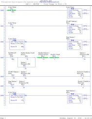
Figure 1.5: Control Block Diagram.<br />
5
1.4 Flow Charts<br />
Flow charts were created to map the desired function of the C programs which<br />
can be seen in Appendix E. Flow charts for the defensive and offensive controller<br />
programs can be seen in Figures 1.6 and 1.7 respectively.<br />
Figure 1.6: Flow chart of defensive controller program.<br />
6
1.5 Schematics<br />
Figure 1.7: Flow chart of defensive controller program.<br />
For ease of manufacturability, both robots used very similar wiring layouts. The<br />
schematics for both of these layouts can be seen in Appendix B.<br />
1.6 Calculations<br />
Using Kinematics equations, the required velocity of the ball was determined to<br />
be 29.4 ft/s. This would allow the ball to cross the playing field in 0.225 seconds with a<br />
7
maximum height of 4 inches above where it is fired. Robot velocities were calculated for<br />
several different gear ratios. This information was used to choose the proper gear ratio.<br />
The selected gear ratio was 41.7:1 which was capable moving the robot between 1.06 ft/s<br />
to 1.32 ft/s. All of the calculations used to obtain these values can be seen in Appendix<br />
C.<br />
1.7 Projected Budget, Weight Inventory, and BOM<br />
All of the supplies which were not directly purchased from a supplier were<br />
researched and priced. The final price for both robots was $121.68. The mass of each<br />
part on the robot was measured, the total mass came to 0.593 kg for the offensive robot<br />
and 0.498 kg for the defensive robots. All of the researched prices, receipts for purchased<br />
products, and the weight inventory can be seen in appendix D.<br />
2. Test Results<br />
2.1 Simulation Results<br />
Simulations were conducted to determine motion of the robots prior to placing<br />
them on the playing field. Using proximity sensors, the actual competition playing field<br />
is to supply the robots with 4 analog signals ranging from 0 to 5 volts, depending on the<br />
robot’s distance from the sensor. The greater the distance between the robot and the<br />
proximity sensor, the greater the voltage supplied, and the greater the analog signal.<br />
In order to simulate position data, variable power supplies were used to generate<br />
analog position feedback. The output voltage on two power supplies was varied between<br />
0 and 5 volts and fed into port A of the ATMega32. The robot controllers took advantage<br />
of the ATMega32 onboard analog-to-digital converter, and the simulated position voltage<br />
was correctly converted on 2 analog input channels. As expected, the controller program<br />
output motor voltage in an attempt to track the enemy and mirror its simulated position.<br />
With the exception of frequently overshooting the enemy’s simulated position, the<br />
controller program correctly tracked and mirrored its attacker. Analysis of the controller<br />
program showed a tendency for the robot to decelerate at the same rate as it would<br />
accelerate, causing the robot to overshoot its desired position. Code was added which<br />
8
allowed the robot controller to monitor its position more accurately, decreasing the<br />
amount of overshoot.<br />
2.2 Performance Testing<br />
Several tests were performed before conducting the individual in-class tests. One<br />
of the first tests was to compare the performance of two gearboxes—the Tamiya High-<br />
Speed Gearbox and the Tamiya High-Power Gearbox. The gearboxes were tested<br />
by supplying each with a range of voltages and weight loads, then measuring the<br />
resulting velocities. It was observed that the high-speed gearbox indeed had higher<br />
velocity, but could not handle the required weight loads. However, the high-power<br />
gearbox met our velocity requirements throughout the voltage range, and was also<br />
capable of handling the expected weight loads.<br />
Once a gearbox had been chosen, the robot was tested on the track. It was<br />
observed that the robot bound with the truck and could not move. This was fixed by<br />
enlarging the slot that the pins go through.<br />
The barrel was tested by supplying 85 psi through a ¼” air hose. Initially, the ball<br />
did not have enough velocity to cross the playing field. The barrel was modified by<br />
covering the holes with electrical tape and retested. This modification gave the ball<br />
enough velocity to cross the field and score a goal.<br />
Several tests were performed on the program. Once the program was functioning<br />
properly, there were still several calibration problems. The defensive program was<br />
modified to stop the motor upon reaching the desired destination so that it did not<br />
overshoot. The offensive program was calibrated to find desired shooting positions that<br />
were not blocked by the opposing team’s defensive robot.<br />
2.3 Results of Formal Tests<br />
There were three main in-class tests of the robot’s function. For the first test, the<br />
base of the robot was completed and the robot’s ability to move on the track was<br />
demonstrated. For the second test, the mechanical aspects of both the offensive and<br />
defensive robots were completed. Both robots traversed the path without binding on the<br />
truck and the offensive robot fired a ball with sufficient velocity to score a goal. The goal<br />
9
of the final in-class test was a test of the defensive robot’s control system. The defensive<br />
robot was able to track the truck on the opposite side of the playing field using signals<br />
sent through the DB-25 connector.<br />
Several problems with the robots were noted from these tests. One of the first<br />
significant observations was that when 5 volts was supplied instantaneously to the motor,<br />
the motor produced so much torque that the front wheels lifted off the track causing the<br />
truck to bind. The problem was fixed by ramping up the voltage to the motor.<br />
A second observation was that the defensive robot tended to overshoot its desired<br />
location when tracking the opposite truck. It was determined that this was due to large<br />
acceleration caused by a function in the code. The function not only caused the robot to<br />
accelerate when beginning to move but also caused the robot to decelerate when<br />
stopping, in turn causing the robot to overshoot its desired location. This was fixed by<br />
eliminating the robot’s ability to decelerate and changing the code so that, slightly before<br />
reaching its desired location, the voltage was completely shut off.<br />
2.4 Comparison of Overall Score Estimates<br />
Where<br />
The scoring from the competition will be calculated with the following equation:<br />
S = Shots blocked by opponent<br />
H = Shots scored<br />
C = Cost of both robots<br />
B = Build Quality<br />
T = Theory rating<br />
M = Mass of both robots<br />
S<br />
2<br />
H<br />
C<br />
4<br />
−2<br />
80 −B<br />
−T<br />
⎛ M ⎞<br />
( 4)<br />
( 10)<br />
( 10)<br />
⎜ ⎟<br />
⎝ 0.<br />
5 ⎠<br />
10<br />
(2.1)<br />
It is desired to have to lowest score possible. The effect of the final score by each<br />
variable was determined by only changing one variable at a time and keeping every other<br />
variable constant, S = 5, H = 5, C = 175, B = 0.9, T = 0.7, M =0.9 From this it was<br />
determined that the best way to have a low score is to miss as few shots as possible.
The robot is expected to have accuracy of at least 70% if it fires all of the possible<br />
balls in the two minute interval the expected score will be:<br />
3.0 Conclusions<br />
3<br />
2<br />
7<br />
−2<br />
(<br />
4)<br />
175<br />
80<br />
( 10)<br />
−<br />
0.<br />
9<br />
( 10)<br />
11<br />
−<br />
0.<br />
7<br />
⎛ 0.<br />
9 ⎞<br />
⎜ ⎟<br />
⎝ 0.<br />
5 ⎠<br />
4<br />
= 1.<br />
005<br />
(1) Premature exclusion of any ideas submitted during brainstorming was detrimental<br />
to the development of the team and teamwork. As the project progressed, the<br />
team learned that regardless of frivolity all ideas submitted were to be given their<br />
due attention in order to cultivate the best design from all team members.<br />
(2) Crude hand sketches were used to communicate initial designs. As the project<br />
approached the decision-making phase, 3D computer models were necessary to<br />
determine the physical dimensions and to perform mass analysis, both critical in<br />
meeting project requirements.<br />
(3) After many calculations, three items were chosen as the most influential in<br />
determination of the estimated final score: (a) total mass, (b) total cost, and (c)<br />
total projectiles blocked. The benefit of mass reduction was worth far more than<br />
the extra strength provided by thicker plates and supports. The thickness of the<br />
chassis was reduced to 1/16 in. and most unneeded material was removed. Total<br />
cost was reduced by relying on in-house fabrication of several components. The<br />
reduction in mass allowed an increase in speed and acceleration, thereby allowing<br />
the defensive robot to block a greater number of projectiles.<br />
(4) The team learned that “Attention to Detail” was the best approach to component<br />
fabrication and mechanical and electrical assembly. Too often the most minute of<br />
details was overlooked and resulted in prolonged and unnecessary<br />
troubleshooting. “Do the job right the first time” eventually became the team<br />
mantra.<br />
(5) Due to limited time and playing field availability, simulations were absolutely<br />
necessary. During the controller design and programming phase especially, a<br />
simulated position generator was used to save time that would translate to money<br />
in the real world.
(6) During initial competitions versus EGR101 students it was seen that EGR345<br />
robots had a significant advantage with respect to speed and reaction time.<br />
However, as the competitions progressed, the autonomous robots bore an<br />
increasingly obvious disadvantage against their human-controlled counterparts.<br />
The human element allowed for learning and adaptation, while the autonomous<br />
robots were “hard-coded” to perform in a limited, eventually predictable manner.<br />
4.0 Recommendations<br />
(1) While mass reduction was a benefit to the overall calculated project score, it<br />
eventually proved to be detrimental in the long run, causing slipping and loss of<br />
responsiveness. Further analysis should be performed in order to determine the<br />
most effective total mass and mass distribution for both robots.<br />
(2) During the course of fabrication, assembly, and testing, electrical components<br />
were found to be extremely sensitive to their thermal and conductive<br />
environment. An investigation should be undergone in order to determine the<br />
optimal placement of the electrical components to prevent exposure to heat, static<br />
electricity, and inadvertent short-circuits.<br />
(3) The storage capacity of the current circuit boards would certainly be challenged<br />
by more proliferative programs (i.e. artificial intelligence). Since these advanced<br />
programming techniques would increase the efficiency and effectiveness of an<br />
autonomous robot, further programming should commence. Additionally,<br />
research should be conducted that may indicate whether a more powerful<br />
microprocessor would benefit this project after such programming is completed.<br />
12
Appendix A: Drawings<br />
13
Appendix B: Electrical Schematics<br />
28
Defensive Robot<br />
29
Offensive Robot<br />
30
Appendix C: Calculations<br />
31
Calculated Ball velocity<br />
Kinematics equations can be written in the x and y directions using the equation<br />
1<br />
s = s0<br />
+ v0<br />
+ at<br />
2<br />
Where s is the final position of the ball, s0 is the initial position of the ball, v0 is the initial<br />
velocity of the ball, a is the acceleration of the ball, and t is the time that the ball travels.<br />
Assuming that the angle is 10°, the resultant equation in the y direction is:<br />
In the x direction, the resultant equation is:<br />
1 ft<br />
0. 333 ft = 0 ft + v0<br />
sin( 10)<br />
+ ( −32.<br />
2 ) t 2<br />
2 s<br />
1 ft<br />
6. 5 ft = 0 ft + v0<br />
cos( 10)<br />
t + ( 0 ) t 2<br />
2 s<br />
Since there are 2 equations with two unknowns, t and v0 can be solved for.<br />
t = 0.<br />
225<br />
v<br />
0 =<br />
29.<br />
4<br />
s<br />
ft<br />
s<br />
Gear Ratio Calculations<br />
To purchase the appropriate motor, calculations were performed to determine the<br />
required voltage and RPM ratings based on the use of a 2 in. diameter wheel/tire:<br />
32<br />
2<br />
2<br />
2
Based on the gearbox and motor manufacturers’ specifications, final drive-shaft angular<br />
velocities were calculated for varying gear ratios as follows:<br />
Rated motor velocity range @ gear ratio = drive-shaft velocity range<br />
5040 RPM – 6300 RPM @ 64.8:1 = 78 RPM – 97 RPM<br />
33
Appendix D: Receipts and Cost Validation<br />
35
BOM<br />
Item #<br />
Item Description<br />
Qty.<br />
Offense<br />
Table 1.1: Project budget and weight inventory.<br />
Qty.<br />
Defense<br />
Total<br />
Qty.<br />
Cost per<br />
Unit<br />
14 Base plate 1 1 2 $2.87<br />
3 Barrel 1 0 1 $3.89<br />
9 Top Hinge 1 0 1 $0.35<br />
10 Bottom Hinge 1 0 1 $0.35<br />
6 Cage 1 1 2 $1.33<br />
18 Rear Pillow Plock 2 2 4 $0.04<br />
7 Fron Pillow Plock 2 2 4 $0.05<br />
16 Wheel 4 4 8 $0.60<br />
16 Tire 4 4 8 $0.30<br />
19 Axles<br />
2 2<br />
15 Spacer 4 4 8 $0.23<br />
2 Barrel cap 1 0 1 $0.34<br />
1 Top Plate 1 1 2 $0.43<br />
12 Coupler 4 4 8 $0.06<br />
11 Bushings 4 4 8 $0.05<br />
16 Nylon Fastener 4 4 8 $0.21<br />
17 FHCS, 6-32 x 1/4 14 12 26 $0.07<br />
8 Gearbox/motor<br />
4 Misc. Electrical Components<br />
5 Mega32 microcontroller<br />
*Supplier abbreviations<br />
McMC McMaster-Carr<br />
GVSU <strong>Grand</strong> <strong>Valley</strong> <strong>State</strong> <strong>University</strong><br />
ZR Zagros Robotics<br />
TBB Toy Brick Brigade<br />
RC Radio Shack<br />
1 1<br />
1 1<br />
1 1<br />
4<br />
2<br />
2<br />
2<br />
Total Cost<br />
per Item<br />
36<br />
Supplier*<br />
Supplier<br />
Part #<br />
$5.74 McMC 8199K33<br />
$3.89<br />
$0.35<br />
$0.35<br />
$2.66<br />
$0.16<br />
$0.20<br />
$4.80<br />
$2.40<br />
Material<br />
Mass per Unit<br />
(kg)<br />
Aluminum 0.039<br />
McMC 89965K128 Aluminum 0.141<br />
McMC 8975K64 Aluminum 0.011<br />
McMC 8975K65 0.007<br />
Kutsches Aluminum 0.053<br />
McMC 9536K19 0.005<br />
McMC 9536K19 Aluminum 0.012<br />
TBB 6595 Plastic 0.016<br />
TBB 6594 Rubber 0.010<br />
Tot. Mass Off.<br />
Robot (kg)<br />
Tot. Mass Def.<br />
Robot (kg)<br />
0.039 0.039<br />
0.141 0.000<br />
0.011 0.000<br />
0.007 0.000<br />
0.053 0.053<br />
0.010 0.010<br />
0.024 0.024<br />
0.064 0.064<br />
0.040 0.040<br />
$0.34 $1.36 FAB 88625K63 Steel 0.014 0.028 0.028<br />
$1.84 Lowes<br />
$0.34<br />
Nylon 0.001<br />
McMC 86985K56 Aluminum 0.014<br />
$0.86 McMC 8199K33<br />
$0.48<br />
$0.40<br />
$1.68<br />
$1.81<br />
Aluminum 0.005<br />
Kutsches Aluminum 0.003<br />
McMC 8538K16 Nylon 0.001<br />
Lowes 0.001<br />
McMC 92210A196 Steel 0.001<br />
0.004 0.004<br />
0.014 0.000<br />
0.005 0.005<br />
0.012 0.012<br />
0.004 0.004<br />
0.004 0.004<br />
0.014 0.012<br />
$9.95 $19.90 ZR 72003 N/A 0.055 0.055 0.055<br />
$6.23 $12.46 RC 0.029 0.029 0.029<br />
$30.00 $60.00 GVSU N/A 0.035 0.035 0.035<br />
Total Cost $121.68 Total Mass per Robot 0.593 0.418
--------------------------------------<br />
Order Date: 10/4/2006 6:33:57 PM<br />
Payment By: Paypal.com<br />
Buyer Requests Insurance: No<br />
--------------------------------------<br />
Comments from Buyer:<br />
--------------------------------------<br />
Order Batch Summary:<br />
--------------------------------------<br />
Total Items: 16<br />
Unique Items (lots): 2<br />
Total: $7.20<br />
--------------------------------------<br />
Items in Order:<br />
--------------------------------------<br />
[Used] Black Tire 49.6 x 28 VR (x8) ..... $0.30 each = $2.40<br />
[Used] Dark Gray Wheel 49.6 x 28 VR with Axle Hole (x8) ..... $0.60<br />
each =<br />
$4.80<br />
--------------------------------------<br />
Buyer Information:<br />
--------------------------------------<br />
BrickLink Username: cody_116 (0)<br />
E-Mail: kodice_116@hotmail.com<br />
IP Address: 148.61.176.128<br />
Address:<br />
cody Holstege<br />
10599 taylor street<br />
Zeeland, MI 49464<br />
USA<br />
--------------------------------------<br />
Seller Information:<br />
--------------------------------------<br />
BrickLink Username: ToyBrickBrigade (8032)<br />
E-Mail: bricklink@toybrickbrigade.com<br />
BrickLink Store Name: Toy Brick Brigade<br />
http://www.BrickLink.com/store.asp?p=ToyBrickBrigade<br />
41
Top and bottom Hinge Plates:<br />
Alloy 6061 Aluminum Square Bar 1/2" Square, 6' Length<br />
In stock at $16.41 Each<br />
Cost: $0.035 / foot<br />
Barrel:<br />
McMaster Prices<br />
9008K23<br />
89965K128<br />
(Same as 89965K781)<br />
Aluminum Tubing 1-3/4" Od, , 1.62" Id, .065" Wall Thickness, 3'L<br />
In stock at $20.02 Each<br />
Cost: $0.56 / foot<br />
Base and Top Plates<br />
8199K33<br />
Alloy 5052 Aluminum Sheet W/#4 Satin Finish .062" Thick, 12" X 24"<br />
In stock at $20.63 Each<br />
Cost: $0.072 / square inch<br />
Pillow Blocks<br />
Colored Aluminum Shim Stock .025" Thick, 6" X 24", White<br />
In stock at $6.94 Each<br />
Cost: $0.048 / square inch<br />
Axles<br />
9536K19<br />
88625K63<br />
O1 Tool Steel Tight-Tolerance Rod 4 Millimeter Diameter, 3' Length<br />
In stock at $2.22 Each<br />
Cost: $0.062 / inch<br />
Barrel Cap<br />
42
Alloy 2024 Aluminum Rod 7/8" Diameter, 1' Length<br />
In stock at $9.12 Each<br />
Cost $0.913 / in<br />
Bushings<br />
White Nylon 6/6 Rod 3/8" Diameter<br />
In stock at $0.55 per Ft.<br />
This product is sold in Lengths of 5 Ft.<br />
Cost: $0.05 / foot<br />
Fasteners:<br />
86985K411<br />
(Same as 86985K56)<br />
8538K16<br />
92949A144<br />
18-8 Ss Button Head Socket Cap Screw 6-32 Thread, 1/4" Length<br />
In stock at $5.29 per Pack<br />
This product is sold in Packs of 100<br />
Cost: $0.053 / fastener<br />
43
Appendix E: C Programs<br />
44
Defensive Robot Controller Program<br />
// Include header files, .c file<br />
#include <br />
#include <br />
#include <br />
#include <br />
#include "sio.c"<br />
//======================================================================================<br />
// Global Definitions<br />
#define c_kinetic_pos 0xC0 // Define kinetic friction coefficient for + direction<br />
#define c_kinetic_neg 0xC0 // Define kinetic friction coefficient for - direction<br />
#define c_static_pos 0xC0 // Define static friction coefficient for + direction<br />
#define c_static_neg 0xC0 // Define static friction coefficient for - direction<br />
#define c_max 255 // Define maximum position<br />
#define c_min 255 // Define magnitude of minimum position<br />
#define CLK_ms 10 // Set the updates for every 10ms<br />
#define T 10 // Define as 10 ms, must divide by 1000 later<br />
#define Kp 10 // Define to 1,3,1<br />
#define Ki 0 // Define to 1,1,3<br />
#define Kd 0<br />
#define US_DEF 1<br />
#define THEM_OFF 3<br />
#define THRESHOLD 15<br />
#define mult 3.0<br />
int moving = 0; // Set variable to show it starts without moving<br />
int e_sum = 0; // Used in integrate function<br />
int prev_err = 0; // used in derivitive function<br />
unsigned int CNT_timer1; // Time variable<br />
volatile unsigned int CLK_ticks = 0; // Current number of ms<br />
volatile unsigned int CLK_seconds = 0; // Current number of seconds<br />
int rpos[5];<br />
int pos_last = 0;<br />
//======================================================================================<br />
// Function definitions<br />
//<br />
//......................................................................................<br />
int integrate(int e)<br />
{<br />
e_sum += e*T;<br />
}<br />
if(e_sum > 10000) e_sum = 10000; // Set an upper limit<br />
if(e_sum < -10000) e_sum = -10000; // Set a lower limit<br />
return e_sum;<br />
//......................................................................................<br />
int derivitive(int e)<br />
{<br />
int diff;<br />
diff = (e - prev_err)/10;<br />
45
eturn diff;<br />
}<br />
//......................................................................................<br />
int controller(int Cd, int Cf)<br />
{<br />
int Ce; // Error variable<br />
int Cw; // Corrected count<br />
}<br />
Ce = Cd - Cf;<br />
Cw = (Kp * Ce) + (Ki * integrate(Ce) / 1000) + (Kd * derivitive(Ce));<br />
if(US_DEF == 1) {<br />
if((rpos[THEM_OFF] < THRESHOLD) && (rpos[US_DEF] < THRESHOLD)) Cw = 0;<br />
else Cw *= -1;<br />
}<br />
return Cw;<br />
//......................................................................................<br />
void AD_setup()<br />
{<br />
ADCSRA = 0x80;// turn on ADC<br />
DDRA = (unsigned char)0; // set port A to input<br />
}<br />
//......................................................................................<br />
void AD_read(void) { // interrupt driven encoder update<br />
int count;<br />
for (count = 0; count < 4; count++) {<br />
ADMUX = (0x40 + count); // REFS1=0,REFS0=1,ADLAR=0,MUX4=0 |<br />
MUX3=0,MUX2=0,MUX1=0,MUX0=1<br />
ADCSRA = 0xC0;<br />
while ((ADCSRA & _BV(ADSC)) != 0);<br />
ADCSRA = 0xC0;<br />
while ((ADCSRA & _BV(ADSC)) != 0);<br />
rpos[count + 1] = ADCW >> 2;<br />
}<br />
}<br />
if(pos_last != rpos[US_DEF])<br />
{<br />
moving = 1;<br />
}<br />
else<br />
{<br />
moving = 0;<br />
}<br />
//......................................................................................<br />
int deadband(int c_wanted)<br />
{// Call this routine when updating<br />
int c_pos;<br />
int c_neg;<br />
int c_adjusted;<br />
if(moving == 1) // If moving -> kinetic<br />
{<br />
c_pos = c_kinetic_pos;<br />
c_neg = c_kinetic_neg;<br />
}<br />
else // Not moving -> static<br />
{<br />
c_pos = c_static_pos;<br />
c_neg = c_static_neg;<br />
}<br />
46
}<br />
if(c_wanted == 0)<br />
{ // Turn off the output<br />
c_adjusted = 0;<br />
}<br />
else if(c_wanted > 0)<br />
{ // Positive motion<br />
c_adjusted = c_pos + (unsigned)(c_max - c_pos) * c_wanted / c_max;<br />
if(c_adjusted > c_max)<br />
c_adjusted = c_max;<br />
}<br />
else { //Negative motion<br />
c_adjusted = -c_neg - (unsigned)(c_min - c_neg) * -c_wanted / c_min;<br />
if(c_adjusted < -c_min) c_adjusted = -c_min;<br />
}<br />
return c_adjusted;<br />
//......................................................................................<br />
void PWM_init()<br />
{ // Initialize the PWM outputs, configure<br />
}<br />
DDRD |= (1 = 0)<br />
{ // Set the direction bits to CW on, CCW off<br />
PORTC = (PINC & 0xFC) | 0x02; /* bit 1 on, 0 off */<br />
if(v_adjusted > 255){ // Clip output over maximum<br />
RefSignal = 255;<br />
} else{<br />
RefSignal = v_adjusted;<br />
}<br />
} else{ // Reverse output sign<br />
// Set the direction bits to CW off, CCW on<br />
47
}<br />
}<br />
PORTC = (PINC & 0xFC) | 0x01; // bit 0 on, 1 off<br />
if(v_adjusted < -255){ // Clip output below minimum<br />
RefSignal = 255;<br />
} else{<br />
RefSignal = -v_adjusted; /* flip sign */<br />
}<br />
return RefSignal;<br />
//......................................................................................<br />
void IO_update()<br />
{ // This routine will run once per interrupt to update PWM<br />
}<br />
AD_read();<br />
PWM_update(v_output(deadband(controller(rpos[US_DEF],rpos[THEM_OFF]))));<br />
//......................................................................................<br />
SIGNAL(SIG_OVERFLOW0){<br />
}<br />
CLK_ticks += CLK_ms;<br />
if(CLK_ticks >= 1000)<br />
{ // The number of interrupts between output changes<br />
CLK_ticks = CLK_ticks - 1000;<br />
CLK_seconds++;<br />
}<br />
IO_update();<br />
TCNT0 = CNT_timer1;<br />
sei();<br />
//......................................................................................<br />
void CLK_setup()<br />
{ // Start the interrupt service routine<br />
TCCR0 = (0
{<br />
}<br />
PWM_init();<br />
sio_init();<br />
AD_setup();<br />
CLK_setup();<br />
DDRB = 0x00;<br />
//======================================================================================<br />
// Main Program Loop<br />
int main(){<br />
}<br />
while((PINB & 0x01) != 1);<br />
IO_setup();<br />
while((PINB & 0x01) == 1)<br />
{<br />
}<br />
outln("outloop");<br />
OCR1A = 0x00;<br />
sio_cleanup();<br />
return 1;<br />
49
Offensive Robot Controller Program<br />
// AUTHOR: TEAM 6<br />
// COURSE: EGR345 PROJECT<br />
// DATE: 11-12-06<br />
// FILENAME: OFFENSE_V1.C<br />
// DESCRIPTION: THIS PROGRAM IMPLEMENTS A MOSTLY-AUTONOMOUS MOTION CONTROLLER FOR<br />
// THE DEFENSIVE ROBOT.<br />
#include <br />
#include <br />
#include <br />
#include <br />
#define C_MAX 255 // Maximum PWM output<br />
#define C_MIN 255 // Minimum PWM output<br />
#define CLK_ms 10 // update every 10 ms<br />
#define US_OFF 1<br />
#define THEM_OFF 3<br />
#define THEM_DEF 4<br />
#define OPEN 1<br />
#define CLOSED 0<br />
#define BALL 1<br />
#define NO_BALL 0<br />
#define PLAY_GAME 1<br />
#define END_GAME 0<br />
int accel = 16,<br />
direction = 0,<br />
moving = 0, // Motor starts from rest<br />
pwm_out = 0, // PWM output<br />
SNEG = 0x80, // PWM output that overcomes static friction, negative direction<br />
SPOS = 0x80, // PWM output that overcomes static friction, positive direction<br />
KNEG = 0x80, // Lowest PWM output that keeps motor moving, negative direction<br />
KPOS = 0x80, // Lowest PWM output that keeps motor moving, positive direction<br />
rpos[5],<br />
START = 0,<br />
Goal[] = {0, 0, 0, 0},<br />
gmin[] = {0, 21, 106, 191},<br />
gmax[] = {0, 63, 149, 234};<br />
unsigned int CNT_timer0; // The delay time<br />
// FUNCTION PROTOTYPES<br />
void AD_setup(void);<br />
int db(int c_target);<br />
void PWM_init();<br />
void PWM_update(int value);<br />
int v_out(int v_adj);<br />
void IO_setup();<br />
void IO_update();<br />
void CLK_setup(void);<br />
int Reload(void);<br />
int AttackGoal(int goal);<br />
void FireCannon(void);<br />
void Delay(int ticks);<br />
// FUNCTION DECLARATIONS<br />
void Delay(int ticks)<br />
{<br />
// ticks are approximately 1ms<br />
volatile int i, j;<br />
for(i = 0; i < ticks; i++)<br />
{<br />
for(j = 0; j < 1000; j++){}<br />
}<br />
}<br />
50
************************************************************************************<br />
void FireCannon(void) {<br />
PORTC |= PC5; // Activate air supply to launch ball...<br />
Delay(500); // ...wait 0.500 sec for ball to leave barrel...<br />
PORTC &= PC5; // ...deactivate air supply.<br />
}<br />
//************************************************************************************<br />
int AttackGoal(int goal) {<br />
// If our offense is closer to prox than min location of goal...<br />
if (rpos[US_OFF] < gmin[goal]) {<br />
// ...accelerate toward min location of goal...<br />
while (rpos[US_OFF] < gmin[goal]) {<br />
if ((pwm_out += accel) > 255) pwm_out = 255;<br />
}<br />
// ...and fire on the move.<br />
FireCannon();<br />
return NO_BALL;<br />
}<br />
// If our offense is further from the prox than max location of goal...<br />
else if (rpos[US_OFF] > gmax[goal]) {<br />
// ...accelerate toward max location of goal...<br />
while (rpos[US_OFF] > gmax[goal]) {<br />
if ((pwm_out -= accel) > -255) pwm_out = -255;<br />
}<br />
// ...and fire on the move.<br />
FireCannon();<br />
return NO_BALL;<br />
}<br />
// Our offense must already be located at the open goal, fire where we stand.<br />
else FireCannon();<br />
return NO_BALL;<br />
}<br />
//************************************************************************************<br />
int Reload(void) {<br />
// Wherever we are, stop.<br />
pwm_out = 0;<br />
IO_update();<br />
}<br />
// While our offense is not at home position...<br />
while (US_OFF > 0) {<br />
// ...accelerate toward home.<br />
if ((pwm_out -= accel) < -255) pwm_out = -255;<br />
IO_update();<br />
}<br />
// Offense has reached home postion.<br />
// Wait 2 seconds for manual reload.<br />
Delay(2000);<br />
return BALL;<br />
//************************************************************************************<br />
void AD_setup(void) {<br />
DDRA = 0x00; // Set Port A to inputs<br />
}<br />
//************************************************************************************<br />
int db(int c_target) {<br />
int c_pos,<br />
c_neg,<br />
c_adj;<br />
if (moving) {<br />
c_pos = KPOS;<br />
51
}<br />
}<br />
else {<br />
c_neg = KNEG;<br />
c_pos = SPOS;<br />
c_neg = SNEG;<br />
}<br />
if (c_target == 0) { // Turn off output<br />
c_adj = 0;<br />
}<br />
else if (c_target > 0) { // Positive output<br />
c_adj = c_pos + (unsigned)(C_MAX - c_pos) * c_target / C_MAX;<br />
if (c_adj > C_MAX) c_adj = C_MAX;<br />
}<br />
else { // Negative output<br />
c_adj = -c_neg - (unsigned)(C_MIN - c_neg) * -c_target / C_MIN;<br />
if (c_adj < -C_MIN) c_adj = -C_MIN;<br />
}<br />
return c_adj;<br />
//************************************************************************************<br />
void PWM_init() { // Initialize PWM output<br />
DDRD |= (1 255) {<br />
RefSig = 255;<br />
}<br />
else {<br />
RefSig = v_adj;<br />
}<br />
}<br />
else { // Set CW off, CCW on<br />
PORTC = (PINC & 0xFC) | 0x01; // Bit 1 off, 0 on<br />
if (v_adj < -255) {<br />
RefSig = 255;<br />
}<br />
else {<br />
RefSig = -v_adj;<br />
}<br />
}<br />
return RefSig;<br />
}<br />
//************************************************************************************<br />
void IO_setup() {<br />
CLK_setup();<br />
PWM_init();<br />
AD_setup();<br />
DDRB = 0x00; // Set PB3 to digital input for "Start Game"<br />
}<br />
52
************************************************************************************<br />
void IO_update() {<br />
PWM_update(v_out(db(pwm_out)));<br />
}<br />
//************************************************************************************<br />
SIGNAL(SIG_OVERFLOW0) {<br />
IO_update();<br />
TCNT0 = CNT_timer0;<br />
// Change to and read ADC channel 0 for our offense position<br />
ADMUX = 0x40; // REFS1=0,REFS0=1,ADLAR=0,MUX4=0 | MUX3=0,MUX2=0,MUX1=0,MUX0=1<br />
ADCSRA = 0xC0;<br />
while ((ADCSRA & _BV(ADSC)) != 0);<br />
ADCSRA = 0xC0;<br />
while ((ADCSRA & _BV(ADSC)) != 0);<br />
rpos[1] = ADCW >> 2;<br />
// Change to and read ADC channel 2 for enemy defense position<br />
ADMUX = 0x42; // REFS1=0,REFS0=1,ADLAR=0,MUX4=0 | MUX3=0,MUX2=0,MUX1=0,MUX0=1<br />
ADCSRA = 0xC0;<br />
while ((ADCSRA & _BV(ADSC)) != 0);<br />
ADCSRA = 0xC0;<br />
while ((ADCSRA & _BV(ADSC)) != 0);<br />
rpos[3] = ADCW >> 2;<br />
// Change to and read ADC channel 3 for enemy offense position<br />
ADMUX = 0x43; // REFS1=0,REFS0=1,ADLAR=0,MUX4=0 | MUX3=0,MUX2=0,MUX1=1,MUX0=0<br />
ADCSRA = 0xC0;<br />
while ((ADCSRA & _BV(ADSC)) != 0);<br />
ADCSRA = 0xC0;<br />
while ((ADCSRA & _BV(ADSC)) != 0);<br />
rpos[4] = ADCW >> 2;<br />
}<br />
// Check PB3 for START signal<br />
if((PORTB & PB3)==(PB3)) START = 1;<br />
else START = 0;<br />
//************************************************************************************<br />
void CLK_setup(void) { // Start the interrupt service routine<br />
TCCR0 = (0
There is always at least one goal open.<br />
// Determine which goal is currently open.<br />
for (count = 1; count <br />
gmax[count])) &&<br />
((rpos[THEM_OFF] < gmin[count]) || (rpos[THEM_OFF] ><br />
gmin[count])))<br />
Goal[count] = OPEN;<br />
else Goal[count] = CLOSED;<br />
}<br />
}<br />
// Attempt an attack on an open goal.<br />
for (count = 1; count