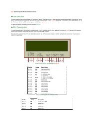
ELET 3132L - Lab #1
ELET 3132L - Lab #1
ELET 3132L - Lab #1

Create successful ePaper yourself
Turn your PDF publications into a flip-book with our unique Google optimized e-Paper software.
Steps 7 through 9: typical CMOS (Complementary Metal Oxide Semiconductor) logic gate<br />
Figure 40: CMOS Logic Gate<br />
Step 7. Construct the circuit shown in Figure 40 above with the +5V supply off..<br />
Step 8. Attach the multimeter between the gate output where Q2, Q3 and Q4 drains are all tied<br />
together (plus lead) and ground (minus lead). Set the multimeter to read Volts DC.<br />
Step 9. Turn on the +5V supply. Measure the output voltage at Q3 drain for each of the four<br />
possible input conditions. Fill in Table 3 below.<br />
Table 3: Truth Table for CMOS Circuit<br />
What logic function does this CMOS gate implement?________________________<br />
<strong>ELET</strong> <strong>3132L</strong> Experiment <strong>#1</strong> 24 of 25