AMMJ - Library
AMMJ - Library
AMMJ - Library

Create successful ePaper yourself
Turn your PDF publications into a flip-book with our unique Google optimized e-Paper software.
<strong>AMMJ</strong> Laser Cladding 10<br />
REPAIR OF COMPRESSOR SHAFT<br />
The compressor shaft is made of martensitic stainless<br />
steel AISI 410 (DIN 1.4006 / X12Cr13). Near the end of<br />
the shaft an area with an axial length of 70 mm was worn<br />
off. The total length of the shaft was about 3,7 m and<br />
the weight was about 1 ton. For laser cladding, stainless<br />
steel powder AISI 316L is used as feedstock. A coating<br />
with a total thickness of 2 mm is required. Since it is not<br />
possible to obtain a coating with a thickness of 2 mm<br />
after a single pass, multiple layers are applied on top<br />
of each other. The typical maximal layer thickness for a<br />
single pass is 1-1,2 mm. After laser cladding about 0,2<br />
mm of the thickness needs to be removed to obtain a<br />
smooth surface.<br />
PRELIMINARY TESTS<br />
Before treating the shaft, experiments are performed on a small bar to<br />
evaluate the quality of the coating in terms of absence of cracking, the<br />
degree of deformation of and the bonding to the substrate. To evaluate the<br />
deformation behaviour, a bar with a diameter of 30 mm and length of 700<br />
mm was cladded at both ends over a length of 20 mm. The results of a<br />
run-out were satisfactory and showed a deformation of only 0,02-0,04 mm.<br />
The cross section of the coating near the beginning is shown in Figure 3.<br />
No cracks in the coating or in the martensitic stainless steel substrate are<br />
present.<br />
Due to the presence of key-seatings, which did not need to be treated,<br />
copper inserts were placed at these positions to prevent these areas being<br />
damaged by the laser beam. The stainless steel 316L material does not<br />
adhere to the copper and the copper insert can be easily removed after<br />
laser cladding.<br />
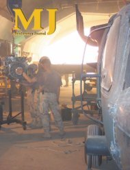
LASER CLADDING OF SHAFT<br />
The same laser cladding parameters as used in the preliminary tests were applied during laser cladding of the<br />
shafts. The experimental setup is shown in Figure 4. The presence of the copper insert at the key-seatings is<br />
visible at the left image of Figure 4. Two layers of stainless steel are applied on top of each other. The shafts<br />
are machined afterwards and the repair was positively evaluated: adequate thickness and good bonding of<br />
coating to substrate, minimal deformation induced by laser cladding, and no porosity in coating.<br />
Figure 4 Setup used for laser cladding of compressor shafts<br />
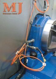
Figure 2 Laser cladding setup used in the study.<br />
Figure 3 Cross section of AISI 316L<br />
on a AISI 410 stainless steel substrate<br />
Vol 24 No 1