Manual - Powermatic
Manual - Powermatic
Manual - Powermatic
Create successful ePaper yourself
Turn your PDF publications into a flip-book with our unique Google optimized e-Paper software.
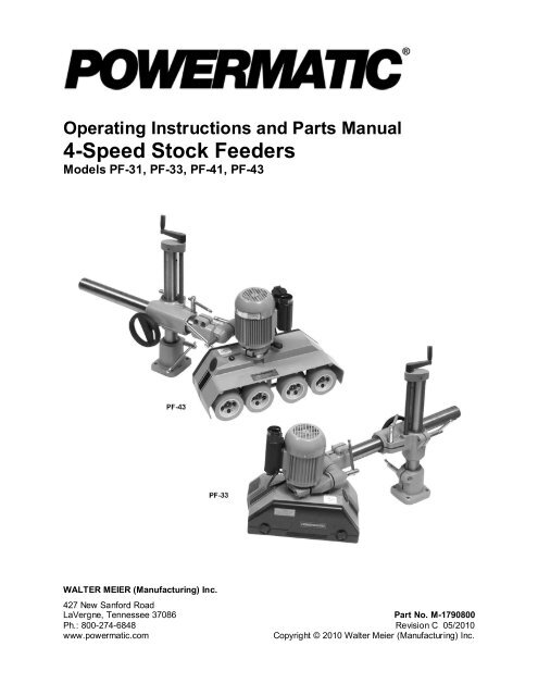
Operating Instructions and Parts <strong>Manual</strong><br />
4-Speed Stock Feeders<br />
Models PF-31, PF-33, PF-41, PF-43<br />
WALTER MEIER (Manufacturing) Inc.<br />
427 New Sanford Road<br />
LaVergne, Tennessee 37086 Part No. M-1790800<br />
Ph.: 800-274-6848 Revision C 05/2010<br />
www.powermatic.com Copyright © 2010 Walter Meier (Manufacturing) Inc.
Warranty and Service<br />
Walter Meier (Manufacturing) Inc., warrants every product it sells. If one of our tools needs service or repair, one of our<br />
Authorized Service Centers located throughout the United States can give you quick service. In most cases, any of these Walter<br />
Meier Authorized Service Centers can authorize warranty repair, assist you in obtaining parts, or perform routine maintenance<br />
and major repair on your POWERMATIC ® tools. For the name of an Authorized Service Center in your area call 1-800-274-6848.<br />
MORE INFORMATION<br />
Walter Meier is consistently adding new products to the line. For complete, up-to-date product information, check with your local<br />
Walter Meier distributor, or visit powermatic.com.<br />
WARRANTY<br />
POWERMATIC products carry a limited warranty which varies in duration based upon the product.<br />
WHAT IS COVERED?<br />
This warranty covers any defects in workmanship or materials subject to the exceptions stated below. Cutting tools, abrasives<br />
and other consumables are excluded from warranty coverage.<br />
WHO IS COVERED?<br />
This warranty covers only the initial purchaser of the product.<br />
WHAT IS THE PERIOD OF COVERAGE?<br />
The general POWERMATIC warranty lasts for the time period specified in the product literature of each product.<br />
WHAT IS NOT COVERED?<br />
The Five Year Warranty does not cover products used for commercial, industrial or educational purposes. Products with a Five<br />
Year Warranty that are used for commercial, industrial or education purposes revert to a One Year Warranty. This warranty does<br />
not cover defects due directly or indirectly to misuse, abuse, negligence or accidents, normal wear-and-tear, improper repair or<br />
alterations, or lack of maintenance.<br />
HOW TO GET SERVICE<br />
The product or part must be returned for examination, postage prepaid, to a location designated by us. For the name of the<br />
location nearest you, please call 1-800-274-6848.<br />
You must provide proof of initial purchase date and an explanation of the complaint must accompany the merchandise. If our<br />
inspection discloses a defect, we will repair or replace the product, or refund the purchase price, at our option.<br />
We will return the repaired product or replacement at our expense unless it is determined by us that there is no defect, or that the<br />
defect resulted from causes not within the scope of our warranty in which case we will, at your direction, dispose of or return the<br />
product. In the event you choose to have the product returned, you will be responsible for the handling and shipping costs of the<br />
return.<br />
HOW STATE LAW APPLIES<br />
This warranty gives you specific legal rights; you may also have other rights which vary from state to state.<br />
LIMITATIONS ON THIS WARRANTY<br />
WALTER MEIER (MANUFACTURING) INC., LIMITS ALL IMPLIED WARRANTIES TO THE PERIOD OF THE LIMITED<br />
WARRANTY FOR EACH PRODUCT. EXCEPT AS STATED HEREIN, ANY IMPLIED WARRANTIES OR MERCHANTABILITY<br />
AND FITNESS ARE EXCLUDED. SOME STATES DO NOT ALLOW LIMITATIONS ON HOW LONG THE IMPLIED WARRANTY<br />
LASTS, SO THE ABOVE LIMITATION MAY NOT APPLY TO YOU.<br />
WALTER MEIER (MANUFACTURING) INC., SHALL IN NO EVENT BE LIABLE FOR DEATH, INJURIES TO PERSONS OR<br />
PROPERTY, OR FOR INCIDENTAL, CONTINGENT, SPECIAL, OR CONSEQUENTIAL DAMAGES ARISING FROM THE USE<br />
OF OUR PRODUCTS. SOME STATES DO NOT ALLOW THE EXCLUSION OR LIMITATION OF INCIDENTAL OR<br />
CONSEQUENTIAL DAMAGES, SO THE ABOVE LIMITATION OR EXCLUSION MAY NOT APPLY TO YOU.<br />
Walter Meier sells through distributors only. The specifications in Walter Meier catalogs are given as general information and are<br />
not binding. Members of Walter Meier reserve the right to effect at any time, without prior notice, those alterations to parts,<br />
fittings, and accessory equipment which they may deem necessary for any reason whatsoever.<br />
2
Table of Contents<br />
Warranty and Service..........................................................................................................................2<br />
Table of Contents ...............................................................................................................................3<br />
Warning .............................................................................................................................................4<br />
Introduction ........................................................................................................................................6<br />
Description .........................................................................................................................................6<br />
Specifications .....................................................................................................................................6<br />
Features and Terminology ...................................................................................................................7<br />
Unpacking ..........................................................................................................................................8<br />
Contents of the Shipping Container ..................................................................................................8<br />
Assembly ...........................................................................................................................................9<br />
Grounding Instructions ...................................................................................................................... 11<br />
Extension Cords ............................................................................................................................ 12<br />
Adjustments ..................................................................................................................................... 12<br />
Basic Feeder Movements .............................................................................................................. 12<br />
Edgewise Stock Feeder Position .................................................................................................... 12<br />
Speed Selection ............................................................................................................................ 12<br />
Operating Controls............................................................................................................................ 13<br />
Operation ......................................................................................................................................... 13<br />
General Operating Instructions ....................................................................................................... 14<br />
When Used with a Shaper.............................................................................................................. 14<br />
When Used with a Table Saw......................................................................................................... 15<br />
When Used with a Jointer .............................................................................................................. 15<br />
Roller Removal/Replacement ......................................................................................................... 16<br />
Lubrication .................................................................................................................................... 17<br />
Replacement Parts ........................................................................................................................... 18<br />
PF-31/33 Feeder Body................................................................................................................... 19<br />
Parts List: PF-31/33 Feeder Body ................................................................................................... 20<br />
PF-41/43 Feeder Body................................................................................................................... 22<br />
Parts List: PF-41/43 Feeder Body ................................................................................................... 23<br />
Parts List: Motor Assembly for PF-31/33 and PF-41/43 .................................................................... 25<br />
Feeder Mounting Assembly for PF-31/33 and PF-41/43 ................................................................... 26<br />
Parts List: Feeder Mounting Assembly for PF-31/33 and PF-41/43 ................................................... 27<br />
Electrical Connections – 3 Phase only................................................................................................ 28<br />
3
Warning<br />
1. Read and understand the entire owner’s manual before attempting assembly or operation.<br />
2. Read and understand the warnings posted on the machine and in this manual. Failure to comply with<br />
all of these warnings may cause serious injury.<br />
3. Replace the warning labels if they become obscured or removed.<br />
4. This stock feeder is designed and intended for use by properly trained and experienced personnel<br />
only. If you are not familiar with the proper and safe operation of a stock feeder, do not use until<br />
proper training and knowledge have been obtained.<br />
5. Do not use this stock feeder for other than its intended use. If used for other purposes, Walter Meier<br />
(Manufacturing) Inc., disclaims any real or implied warranty and holds itself harmless from any injury<br />
that may result from that use.<br />
6. Always wear approved safety glasses/face shields while using this stock feeder. Everyday<br />
eyeglasses only have impact resistant lenses; they are not safety glasses.<br />
7. Before operating this stock feeder, remove tie, rings, watches and other jewelry, and roll sleeves up<br />
past the elbows. Remove all loose clothing and confine long hair. Non-slip footwear or anti-skid floor<br />
strips are recommended. Do not wear gloves.<br />
8. Wear ear protectors (plugs or muffs) during extended periods of operation.<br />
9. Some dust created by power sanding, sawing, grinding, drilling and other construction activities<br />
contain chemicals known to cause cancer, birth defects or other reproductive harm. Some examples<br />
of these chemicals are:<br />
• Lead from lead based paint.<br />
• Crystalline silica from bricks, cement and other masonry products.<br />
• Arsenic and chromium from chemically treated lumber.<br />
Your risk of exposure varies, depending on how often you do this type of work. To reduce your<br />
exposure to these chemicals, work in a well-ventilated area and work with approved safety<br />
equipment, such as face or dust masks that are specifically designed to filter out microscopic<br />
particles.<br />
10. Do not operate this machine while tired or under the influence of drugs, alcohol or any medication.<br />
11. Make certain the switch is in the OFF position before connecting the machine to the power supply.<br />
12. Make certain the machine is properly grounded.<br />
13. Make all machine adjustments or maintenance with the machine unplugged from the power source.<br />
14. Remove adjusting keys and wrenches. Form a habit of checking to see that keys and adjusting<br />
wrenches are removed from the machine before turning it on.<br />
15. Keep safety guards in place at all times when the machine is in use. If removed for maintenance<br />
purposes, use extreme caution and replace the guards immediately upon completion of maintenance.<br />
16. Make sure the stock feeder is firmly secured to an auxiliary machine before use.<br />
17. Check damaged parts. Before further use of the machine, a guard or other part that is damaged<br />
should be carefully checked to determine that it will operate properly and perform its intended<br />
function. Check for alignment of moving parts, binding of moving parts, breakage of parts, mounting<br />
and any other conditions that may affect its operation. A guard or other part that is damaged should<br />
be properly repaired or replaced.<br />
18. Provide for adequate space surrounding work area and non-glare, overhead lighting.<br />
19. Keep the floor around the machine clean and free of scrap material, oil and grease.<br />
20. Keep visitors a safe distance from the work area. Keep children away.<br />
4
21. Make your workshop child proof with padlocks, master switches or by removing starter keys.<br />
22. Give your work undivided attention. Looking around, carrying on a conversation and “horse-play” are<br />
careless acts that can result in serious injury.<br />
23. Maintain a balanced stance at all times so that you do not fall or lean against moving parts. Do not<br />
overreach or use excessive force to perform any machine operation.<br />
24. Use the right tool at the correct speed and feed rate. Do not force a tool or attachment to do a job for<br />
which it was not designed. The right tool will do the job better and safer.<br />
25. Use recommended accessories; improper accessories may be hazardous.<br />
26. Maintain tools with care. Keep tools sharp and clean for the best and safest performance. Follow<br />
instructions for lubricating and changing accessories.<br />
27. Disconnect from power both the stock feeder and the auxiliary machine before cleaning. Use a brush<br />
or compressed air to remove chips or debris — do not use your hands.<br />
28. Do not stand on the machine. Serious injury could occur if the machine tips over.<br />
29. Never leave the feeder or auxiliary machine running unattended. Turn the power off and do not leave<br />
the machine until it comes to a complete stop.<br />
30. Remove loose items and unnecessary work pieces from the area before starting the machine.<br />
Familiarize yourself with the following safety notices used in this manual:<br />
This means that if precautions are not heeded, it may result in minor injury and/or<br />
possible machine damage.<br />
even death.<br />
This means that if precautions are not heeded, it may result in serious injury or possibly<br />
- - SAVE THESE INSTRUCTIONS - -<br />
5
Introduction<br />
This manual is provided by Walter Meier (Manufacturing) Inc., covering the safe operation and<br />
maintenance procedures for the Model PF-31 (single phase), PF-33 (three phase), PF-41 (single phase)<br />
and PF-43 (three phase) Stock Feeders. This manual contains instructions on installation, safety<br />
precautions, general operating procedures, maintenance instructions and parts breakdown. This machine<br />
has been designed and constructed to provide years of trouble free operation if used in accordance with<br />
instructions set forth in this manual. If there are any questions or comments, please contact either your<br />
local supplier or Walter Meier. Walter Meier can also be reached at our web site: www.waltermeier.com.<br />
Description<br />
The PF-series Stock Feeders have a continuous-duty motor and lubricated gearbox that transmit power<br />
to the roller chain and sprockets to feed rollers, providing superior positive feeding for all types of<br />
materials. The support column is fully adjustable with universal joints, and heavy locking mechanisms<br />
secure the feeder in horizontal, vertical or angled positions.<br />
Specifications<br />
Model Number .....................................................................PF-31, PF-33.........................PF-41, PF-43<br />
Stock Number (1Ph, 115V) ....................................................... 1790807K............................. 1790812K<br />
Stock Number (3PH, 230V) ...................................................... 1790800K............................. 1790811K<br />
Stock Number (3Ph, 460V) ....................................................... 1790810K......................................... na<br />
Height with handle (in.) .................................................................. 29-1/2................................... 29-1/2<br />
Width (in.) ........................................................................................... 18................................... 23-1/2<br />
Length – with handle and arm fully extended (in.)............................. 43-1/4................................... 43-1/4<br />
Column Diameter (in.) ...................................................................... 2-1/4..................................... 2-1/4<br />
Feed Rollers (Dia. x W) (in.) ...................................... 4-3/4 x 2-3/8 (Qty. 3).............. 4-3/4 x 2-3/8 (Qty. 4)<br />
Rotation ........................................................................ Forward/Reverse................... Forward/Reverse<br />
Number of Speeds ................................................................................. 4........................................... 4<br />
Range of Speeds (FPM).......................................... 13, 26, 33, 66 (PF-33) ........... 13, 26, 33, 66 (PF-43)<br />
13, 36, 43, 108 (PF-31) 13, 36, 43, 108 (PF-41)<br />
Distance Between Wheels –Center to Center (in.)..................... 5.07 – 5.90........................ 5.23 - 5.93 - 5<br />
Swing (deg.) ...................................................................................... 360....................................... 360<br />
Vertical Movement (in.) .................................................................... 9-3/4..................................... 9-3/4<br />
Horizontal Movement (in.) ............................................................... 18.07.................................... 18.07<br />
Maximum Height of Rollers Parallel to Tabletop (in.) .......................... 8-1/2..................................... 8-1/2<br />
Rollers Vertical Suspension Travel, Approx. (in.)................................. 9/16...................................... 9/16<br />
Motor ........................................................................... TEFC, 1HP, 60Hz.................. TEFC, 1HP, 60Hz<br />
Approximate Net Weight (lbs.) ............................................................ 134....................................... 150<br />
Approximate Shipping Weight (lbs.) .................................................... 143....................................... 158<br />
The above specifications were current at the time this manual was published, but because of our policy of<br />
continuous improvement, Walter Meier reserves the right to change specifications at any time and without<br />
prior notice, without incurring obligations.<br />
6
Features and Terminology<br />
Figure 1<br />
7
Unpacking<br />
Open both cartons and check for shipping<br />
damage. Report any damage immediately to<br />
your distributor and shipping agent. Do not<br />
discard any shipping material until the Stock<br />
Feeder is assembled and running properly.<br />
Compare the contents of the cartons with the<br />
following parts list to make sure all parts are<br />
intact. Missing parts, if any, should be reported<br />
to your distributor. Read the instruction manual<br />
thoroughly for assembly, maintenance and<br />
safety instructions.<br />
Figure 2<br />
8<br />
Contents of the Shipping Container<br />
Carton #1:<br />
1 Stock Feeder<br />
1 Grease Gun (grease not included – follow<br />
instructions on its packaging to fill)<br />
1 Boring Template<br />
1 Owner's <strong>Manual</strong> (not shown)<br />
1 Warranty Card (not shown)<br />
Carton #2:<br />
1 Feeder Mounting Assembly<br />
1 Handle<br />
1 Over Arm<br />
1 Over Arm Cone Assembly<br />
4 Hex Cap Screws, M12x50 (not shown)<br />
4 Spring Washers, M12 (not shown)<br />
Read and understand the entire contents of this manual before attempting set-up<br />
or operation! Failure to comply may cause serious injury.
Assembly<br />
Tools needed for assembly (not provided):<br />
Electric drill<br />
center punch and hammer<br />
10.5mm drill bit<br />
M12 x P1.75 tap<br />
12mm, 14mm and 19mm wrenches<br />
5mm hex wrench<br />
Hardware needed for assembly:<br />
4 M12 spring washers<br />
4 M12 x P1.75 hex cap screws (length will<br />
depend upon thickness of table)<br />
Exposed metal areas of the stock feeder have<br />
been factory coated with a protectant. This<br />
should be removed with a soft cloth and a<br />
cleaner/degreaser. Do not use gasoline,<br />
acetone, lacquer thinner or other highly<br />
flammable substances for this purpose. Avoid<br />
getting solvents near plastic or rubber parts, and<br />
do not use an abrasive pad because it may<br />
scratch metal surfaces.<br />
The stock feeder should be mounted securely to<br />
an auxiliary machine in a well-lighted area.<br />
Leave enough space around the work area for<br />
loading and off-loading stock and general<br />
maintenance.<br />
The stock feeder and the<br />
auxiliary machine to which you are mounting<br />
it should both be disconnected from power<br />
during installation.<br />
Refer to pages 14 through 16 for help in placing<br />
the stock feeder on a shaper, table saw or<br />
jointer.<br />
1. Rest the feeder mounting assembly on the<br />
table of the auxiliary machine to determine<br />
the mounting location. (Figure 3 shows it<br />
being mounted to a table saw). Keep in<br />
mind the length of the over arm, so that after<br />
it is connected to the feeder mounting<br />
assembly it will have enough adjustment for<br />
positioning the stock feeder where needed.<br />
Mark the table if needed to identify the<br />
position.<br />
IMPORTANT: Locate the feeder mounting<br />
assembly so that you will not drill through<br />
ribs or supports beneath the table surface.<br />
2. Remove the feeder mounting assembly from<br />
the table. Find the boring template that was<br />
provided with your stock feeder, and identify<br />
the centerline spacing for the holes in the<br />
column base for your particular model.<br />
9<br />
Figure 3
3. Clean the table surface, then peel away the<br />
backing from the boring template in<br />
increments, as you carefully apply the<br />
boring template onto the table.<br />
4. Center punch and drill four 10.5mm<br />
diameter holes in the table surface, then tap<br />
the holes with M12 x P1.75 threads.<br />
5. Peel off the boring template and discard.<br />
6. Place the column base in position (Figure<br />
4), and align the four holes in the column<br />
base with the holes in the table. Position the<br />
column base so that its locking handle will<br />
be in a convenient position.<br />
7. Insert four M12x50 hex cap screws with four<br />
M12 spring washers through the holes in the<br />
stand. See Figure 4.<br />
8. Tighten the four screws firmly with a wrench.<br />
9. Install the small handle into the hole in the<br />
elevating handle (Figure 5). Screw the small<br />
handle into the hole, then tighten the hex<br />
nut down against the elevating handle using<br />
a 14mm wrench.<br />
10. The small handle should still be able to<br />
rotate freely. If it does not, loosen the hex<br />
nut, back off the socket head cap screw with<br />
a 5mm hex wrench as shown, then retighten<br />
the hex nut.<br />
11. Make sure the handle on the bracket (Figure<br />
6) is loosened enough to allow the insertion<br />
of the over arm into the bracket.<br />
12. Insert the end of the over arm that has the<br />
rack extending all the way to the edge, into<br />
the bracket. (NOTE: The rack will slide<br />
through the slot inside the bracket.) Slide<br />
the over arm in until its rack meshes with the<br />
pinion on the handwheel shaft. You may<br />
have to rotate the handwheel slightly to get<br />
a good mesh.<br />
13. Continue to insert the over-arm, while<br />
rotating the handwheel, until the over arm<br />
protrudes out the back end of the bracket.<br />
The over arm can now be moved simply by<br />
rotating the handwheel.<br />
14. Place the sleeve of the over arm cone<br />
assembly onto the over arm as shown in<br />
Figure 7. Loosen further the two hex cap<br />
screws if needed. Push the cone assembly<br />
onto the over arm as far as it will go.<br />
15. Tighten the two hex cap screws (Figure 7)<br />
with a 14mm wrench.<br />
10<br />
Figure 4<br />
Figure 5<br />
Figure 6<br />
Figure 7
The stock feeder is heavy.<br />
The use of an assistant may be necessary.<br />
16. Place the stock feeder on the table surface,<br />
and lower the over arm so that the clamp is<br />
positioned to accept the stock feeder. (see<br />
“Basic Feeder Movements”, page 12, for<br />
instructions on positioning the over arm.)<br />
17. Mounting the feeder body may be easier if<br />
you loosen the two hex cap screws (shown<br />
in Figure 7) and rotate the over arm cone<br />
assembly so that the clamp is toward the<br />
bottom, as shown in Figure 8. Loosen the<br />
handles and rotate the cones as needed to<br />
get the clamp in position. Re-tighten the<br />
screws and handles before mounting the<br />
feeder body.<br />
18. Unscrew the bolt and the handle (Figure 8)<br />
from the clamp, and remove the outer half of<br />
the clamp.<br />
19. Position the neck of the stock feeder into the<br />
inner half of the clamp, then attach the outer<br />
half of the clamp. Re-install the bolt and<br />
handle and tighten both of them gradually<br />
and in turns, until the clamp is evenly tight<br />
over the stock feeder neck. NOTE: The<br />
seam between the two halves of the clamp<br />
will not close entirely.<br />
The handle (Figure 8) is adjustable. To<br />
tighten it, rotate the handle clockwise, then<br />
lift out on the handle, rotate it<br />
counterclockwise on the pin and release it,<br />
making sure it re-seats itself on the pin.<br />
Continue this procedure until tight. (This<br />
adjustable feature allows the handle to be<br />
re-positioned at any time while remaining<br />
tight.)<br />
Grounding Instructions<br />
Electrical connections must<br />
be made by a qualified electrician in<br />
compliance with all relevant codes. This<br />
machine must be properly grounded to help<br />
prevent electrical shock and possible fatal<br />
injury.<br />
The PF-series Feeders are available in voltages<br />
ranging from 115 to 460, depending on the<br />
model you purchased. Make sure the voltage of<br />
your power supply matches the specifications on<br />
the motor plate of the stock feeder.<br />
The Stock Feeder is not supplied with an<br />
electrical plug. You may either connect an<br />
appropriate UL/CSA listed plug, or “hard-wire”<br />
the machine directly to a service panel.<br />
11<br />
Figure 8<br />
If the stock feeder is to be hard-wired to a panel,<br />
make sure a disconnect is available for the<br />
operator. Also make sure the fuses have been<br />
removed or the breakers have been tripped in<br />
the circuit to which the stock feeder will be<br />
connected. Place a warning placard on the fuse<br />
holder or circuit breaker to prevent it being<br />
turned on while the machine is being wired. The<br />
stock feeder must comply with all local and<br />
national codes after being wired.<br />
This machine must be grounded. In the event of<br />
a malfunction or breakdown, grounding provides<br />
a path of least resistance for electric current, to<br />
reduce the risk of electric shock to the operator.<br />
Improper connection of the equipment-grounding<br />
conductor can result in a risk of electric shock.<br />
The conductor, with insulation having an outer<br />
surface that is green with or without yellow<br />
stripes, is the equipment-grounding conductor. If<br />
repair or replacement of the electric cord or plug<br />
is necessary, do not connect the equipmentgrounding<br />
conductor to a live terminal.
Extension Cords<br />
If an extension cord is necessary, make sure the<br />
cord rating is suitable for the amperage listed on<br />
the machine's motor plate. An undersize cord<br />
will cause a drop in line voltage resulting in loss<br />
of power and overheating.<br />
The chart in Figure 9 shows the correct size<br />
cord to use based on cord length and motor<br />
plate amp rating. If in doubt, use the next<br />
heavier gauge. The smaller the gauge number<br />
the heavier the cord.<br />
Adjustments<br />
Basic Feeder Movements<br />
Refer to Figure10.<br />
To raise or lower the over arm, loosen handle<br />
(A) and rotate elevating handle (B). When<br />
adjustment is complete, re-tighten handle (A).<br />
To move the over arm forward or back, loosen<br />
handle (C) and rotate handwheel (D). When<br />
adjustment is complete, re-tighten handle (C).<br />
To swing the over arm across the table, loosen<br />
handle (E) and swing the over arm to desired<br />
position. Re-tighten handle (E) before operating<br />
the stock feeder.<br />
To rotate the cones to help position the feeder,<br />
loosen handles (F). Tighten handles when<br />
adjustment is complete.<br />
To rotate the stock feeder on its vertical axis,<br />
loosen handle (G) just enough that the stock<br />
feeder will freely rotate. Re-tighten handle (G)<br />
before operating the stock feeder.<br />
Edgewise Stock Feeder Position<br />
The stock feeder can be turned “edgewise” so<br />
that the feed is along the side of the workpiece.<br />
This is useful when edging stock on a shaper or<br />
jointer. The position is achieved using a<br />
combination of cone rotations, as shown in<br />
Figure 11.<br />
Speed Selection<br />
The stock feeder has four speeds, or feed rates:<br />
13, 26, 33 and 66 FPM for the 3-Phase models;<br />
and 13, 36, 43 and 108 FPM for the 1-Phase<br />
models. These speeds are achieved by a<br />
combination of gear position and the setting of<br />
the control switch.<br />
12<br />
Recommended Gauges (AWG) of Extension Cords<br />
Amps<br />
25<br />
feet<br />
Extension Cord Length *<br />
50<br />
feet<br />
75<br />
feet<br />
100<br />
feet<br />
150<br />
feet<br />
200<br />
feet<br />
< 5 16 16 16 14 12 12<br />
5 to 8 16 16 14 12 10 NR<br />
8 to 12 14 14 12 10 NR NR<br />
12 to 15 12 12 10 10 NR NR<br />
15 to 20 10 10 10 NR NR NR<br />
21 to 30 10 NR NR NR NR NR<br />
*based on limiting the line voltage drop to 5V at 150% of the<br />
rated amperes.<br />
NR: Not Recommended.<br />
Figure 9<br />
Figure 10<br />
Figure 11
Disconnect stock feeder<br />
from power source before opening the back<br />
cover or switching gears.<br />
To change the position of the gears:<br />
1. Disconnect machine from power source.<br />
2. Unscrew the two knobs and pull off the back<br />
cover to expose the gear system, shown in<br />
Figure 12.<br />
3. Remove hex nuts and flat washers (A,<br />
Figure 12) with a 14mm wrench.<br />
4. Figure 13 shows the relationship of gear<br />
position to create each of the four speeds. A<br />
similar chart is affixed to the inside of the<br />
back cover on the Stock Feeder.<br />
5. Install new gear configuration, making sure<br />
the notch in each gear slides into the<br />
keyway of the shaft. Push the gears as far<br />
as they will go onto the shafts.<br />
6. Install flat washer and hex nut (A, Figure 12)<br />
on each shaft, and tighten.<br />
7. Re-install back cover and tighten knobs.<br />
Operating Controls<br />
The control switch for 3-phase units is shown in<br />
Figure 14; the control switches for 1-phase units<br />
are shown in Figure 15. Speeds are indicated by<br />
the universal symbols of hare (high speed) and<br />
tortoise (low speed). The switch can be turned<br />
for either forward or reverse direction.<br />
If a jam should occur while<br />
feeding a workpiece, DO NOT turn the stock<br />
feeder to reverse while the auxiliary machine<br />
is still running in forward direction.<br />
If a workpiece becomes jammed, turn off the<br />
stock feeder, and then turn off the auxiliary<br />
machine. Raise the stock feeder in order to clear<br />
the workpiece. Then re-set the feeder height,<br />
turn on auxiliary machine and stock feeder, and<br />
begin the feed over again.<br />
Operation<br />
IMPORTANT: Before operating the stock<br />
feeder, you should be thoroughly familiar with<br />
the safety and operating instructions that<br />
accompanied the auxiliary machine.<br />
Keep hands away from<br />
rollers and cutting tool during operation.<br />
Failure to comply may cause injury.<br />
13<br />
Figure 12<br />
Figure 13<br />
Figure 14<br />
(3-Phase only)<br />
Figure 15<br />
(1-phase only)
General Operating Instructions<br />
1. Make sure all handles on the stock feeder<br />
and the feeder mounting assembly are tight<br />
before operating.<br />
2. The stock feeder should be used in<br />
conjunction with a fence on your auxiliary<br />
machine. The fence should be securely<br />
fixed.<br />
3. The rollers must grip the offcut, as well as<br />
the part of the workpiece still being fed.<br />
Also, the rollers should be set parallel to the<br />
table or fence for proper feed.<br />
4. On some machines, such as a shaper or<br />
jointer, the stock feeder can be mounted so<br />
that the rollers exert pressure from the top,<br />
or mounted edgewise so that the rollers<br />
exert pressure from the side, or mounted at<br />
an intermediate angle for beveled<br />
workpieces.<br />
5. The feed rollers have a spring suspension<br />
which will exert the necessary pressure<br />
against the workpiece. This pressure<br />
increases automatically with feed<br />
resistance, so that a workpiece of varying<br />
thickness can be fed through the stock<br />
feeder without adjustments.<br />
6. When used in horizontal position, the stock<br />
feeder should be adjusted for height so that<br />
the distance between the table and the feed<br />
rollers is approximately 1/8” (3mm) less than<br />
the thickness of the workpiece. See Figure<br />
16.<br />
7. Shaping hardwood with the stock feeder<br />
may increase the friction between workpiece<br />
and table. Keep the work table rust-free and<br />
smooth, by using paste wax or other<br />
necessary means.<br />
8. Various configurations are possible with<br />
your Stock Feeder, depending upon your<br />
auxiliary machine and the type of work<br />
being done. What is important is that the<br />
feeder is positioned in the most effective<br />
and safest manner for the work being<br />
done.<br />
Although the stock feeder<br />
when properly used will greatly reduce the<br />
chance of workpiece kickback, there is still a<br />
potential for kickback. Never stand directly<br />
in the path of the workpiece as it passes<br />
under the stock feeder rollers.<br />
When Used with a Shaper<br />
1. The gap between the fences for the cutter<br />
should be as small as possible.<br />
14<br />
Figure 16
2. To ensure that the workpiece is held firmly<br />
against the fence, set the stock feeder at a<br />
slight angle toward the fence in the direction<br />
of feed. In other words, the outfeed roller<br />
should be approximately 3/16” (5mm) closer<br />
to the fence than the infeed roller. See<br />
Figure 17.<br />
3. When the Stock Feeder is in edgewise<br />
position, it must be inclined slightly towards<br />
the work table in the direction of feed, to<br />
ensure the workpiece remains forced down<br />
against the table. In other words, the<br />
outfeed roller should be approximately 3/16”<br />
closer to the work table than the infeed<br />
roller. See Figure 18.<br />
4. When the Stock Feeder is in the edgewise<br />
position, or angled for a beveled workpiece,<br />
the axis of the cutter should be between the<br />
infeed roller and the center roller (between<br />
the two center rollers on the 4-roller model).<br />
See Figure 18. The center roller should<br />
NOT be directed toward the opening<br />
between the fences, but should act directly<br />
against the fence.<br />
5. When mounting the Stock Feeder in<br />
edgewise position, keep in mind the spring<br />
tension of the rollers. The distance between<br />
the shaper fence and the feed rollers should<br />
be approximately 1/8” (3mm) less than the<br />
thickness of the workpiece (refer to Figure<br />
16).<br />
When Used with a Table Saw<br />
1. Position the 3-roller stock feeder so that the<br />
axis of the saw blade lines up between the<br />
center roller and outfeed roller. (See Figure<br />
19.) Position the 4-roller stock feeder so that<br />
the axis of the saw blade lines up between<br />
the center wheels. These positions will allow<br />
the Stock Feeder to grip the offcut of the<br />
workpiece as it leaves the blade.<br />
2. Rotate the Stock Feeder so that the<br />
direction of feed is angled slightly toward the<br />
fence by approximately 3/16” (5mm); that is,<br />
the outfeed roller should be slightly closer to<br />
the fence than the infeed roller. See Figure<br />
19.<br />
When Used with a Jointer<br />
1. Mount the 3-roller stock feeder on a jointer<br />
so that the cutterhead is between the<br />
outfeed roller and the center roller (Figure<br />
20). The 4-roller stock feeder can be<br />
positioned so that the cutterhead is between<br />
the center rollers.<br />
15<br />
Figure 17<br />
(Stock Feeder in horizontal position)<br />
Figure 18<br />
(Stock Feeder in edgewise position)<br />
Figure 19<br />
Figure 20
2. Some woodworkers prefer to place the<br />
feeder so that all rollers are over the outfeed<br />
table, as shown in Figure 21. The infeed<br />
roller should be approximately 3/16” away<br />
from the lip of the outfeed table at the<br />
cutterhead area.<br />
3. Rotate the Stock Feeder so that the<br />
direction of feed is angled slightly toward the<br />
fence by approximately 3/16” (5mm); that is,<br />
the outfeed roller should be slightly closer to<br />
the fence than the infeed roller. See Figures<br />
20 and 21.<br />
Roller Removal/Replacement<br />
If a feed roller becomes worn or damaged it is<br />
easily replaced. Also, if more clearance is<br />
needed between rollers, the center roller can be<br />
removed.<br />
1. To remove a roller, lower the stock feeder<br />
until it contacts the table of the auxiliary<br />
machine – this will give you purchase for<br />
loosening the screws with a 5mm hex<br />
wrench. When the screws are loose, raise<br />
the feeder off the table to continue removing<br />
the roller(s).<br />
There are four screws in each roller: the two<br />
short screws unite the halves of the roller<br />
hub; the two long screws secure the roller<br />
assembly to the feeder. You only need to<br />
remove the two long screws to remove the<br />
roller assembly. NOTE: Replacement roller<br />
assemblies may have a one-piece hub, and<br />
thus the two short screws will no longer be<br />
needed.) See Figure 22.<br />
2. When a roller assembly is re-mounted to the<br />
stock feeder, make sure all screws are tight.<br />
Maintenance<br />
Before any intervention on<br />
the machine, disconnect it from the electrical<br />
supply by pulling out the plug or switching<br />
off the main switch. Failure to comply may<br />
cause serious injury.<br />
If the power cord is worn, cut, or damaged in<br />
any way, have it replaced immediately.<br />
The rubber tires on the rollers should be kept<br />
clean of grease, sawdust and other debris. Use<br />
a soft cloth with soap and water to wipe down<br />
the tires. DO NOT use a solvent on the rubber<br />
tires.<br />
The mating parts of the cones should be kept<br />
clean. See Figure 23. When disassembling any<br />
of the cones, wipe off both mating parts with a<br />
clean rag before re-assembling.<br />
16<br />
Figure 21<br />
Figure 22<br />
Figure 23
NOTE: These cones are subject to high torque<br />
and it may be necessary to periodically retighten<br />
the handle until the cone surfaces<br />
become securely seated.<br />
Exposed metal areas, such as the column and<br />
the over arm, should be kept clean and free of<br />
rust.<br />
Lubrication<br />
Oil Reservoir<br />
Open the oil cap (shown in Figure 24). The oil<br />
level should be approximately 1-1/2” deep; that<br />
is, about 1” from the rim of the hole. Periodically<br />
check the oil level and top off as needed with 90<br />
weight gear oil.<br />
Completely drain and refill the oil every 1,000<br />
working hours, or every 6 months.<br />
To change the oil:<br />
1. Remove the feeder body from the clamp.<br />
2. Unscrew and remove the oil cap (shown in<br />
Figure 24) and turn the feeder body upside<br />
down to completely drain the oil. (NOTE:<br />
Always dispose of used oil properly.)<br />
3. Turn feeder body right side up, and pour<br />
new oil into the fill hole, until it is about 1”<br />
from the rim.<br />
4. Re-install the oil cap (Figure 24).<br />
Rollers<br />
NOTE: Grease is not provided with the grease<br />
gun. To fill the grease gun, follow the<br />
instructions on its package.<br />
Each of the rollers has a grease fitting located in<br />
the hub center, as shown in Figure 25. Use the<br />
provided grease gun to insert a good quality, allpurpose<br />
grease into these fittings every 200<br />
working hours, or every 30 days.<br />
Also insert grease into the fitting on each tip of<br />
the sprocket shafts, which are located inside the<br />
housing cover as shown in Figure 26.<br />
Chains<br />
Lubricate the drive chains (shown in Figure 12)<br />
with good quality all-purpose grease every 3<br />
months, or more frequently if needed.<br />
Elevating Screw<br />
Occasionally apply a light coat of grease to the<br />
elevating screw of the vertical column (identified<br />
in Figure 1 on page 7).<br />
17<br />
Figure 24<br />
Figure 25<br />
Figure 26
Troubleshooting<br />
Trouble Probable Cause Remedy<br />
Feeder will not start.<br />
Feed rate is not<br />
sufficient; machine<br />
has low power.<br />
Workpiece jams or<br />
moves sluggishly<br />
while passing<br />
beneath rollers.<br />
Workpiece slips while<br />
passing under rollers.<br />
Replacement Parts<br />
Not connected to power source. Check power connections.<br />
Fuse blown, or circuit breaker tripped. Replace fuse, or reset circuit breaker.<br />
Cord damaged. Replace cord.<br />
Starting capacitor is malfunctioning. Replace starting capacitor.<br />
Gears installed incorrectly for the<br />
desired feed rate.<br />
Extension cord too light or too long.<br />
18<br />
Install gears in proper position. See<br />
Figure 13.<br />
Replace with adequate size and<br />
length cord. See Figure 9.<br />
Low current from electrical supply. Contact a qualified electrician.<br />
Rollers too low. Raise feeder.<br />
Rollers too high, no traction. Lower feeder.<br />
Grease or debris on rubber tires. Clean tires.<br />
Replacement parts are listed on the following pages. To order parts or reach our service department, call<br />
1-800-274-6848, Monday through Friday (see our website for business hours, www.powermatic.com).<br />
Having the Model Number and Serial Number of your machine available when you call will allow us to<br />
serve you quickly and accurately.
PF-31/33 Feeder Body<br />
19
Parts List: PF-31/33 Feeder Body<br />
Index No. Part No. Description Size Qty<br />
................ 2192188 ..................PF-31 Feeder Body (1Ph, 115V, 4 speed) ..............................................<br />
................ 2192187 ..................PF-33 Feeder Body (3Ph, 230V, 4 speed) ..............................................<br />
................ 2192189 ..................PF-33 Feeder Body (3PH, 460V, 4 speed)..............................................<br />
1 .............. 6289074 ..................Grease Gun ....................................................................................... 1<br />
2 .............. 6289211 ..................Grease Fitting..................................................................................... 3<br />
3 .............. 6289212 ..................Roller Hub Spring ............................................................................... 3<br />
4 .............. 6288938A................Tube .................................................................................................. 3<br />
5 .............. 6289125A................Sprocket Shaft .................................................................................... 2<br />
6 .............. JPF3-041A ..............Case Cover ........................................................................................ 3<br />
7 .............. 6288750 ..................Socket Head Cap Screw ...................................M8 x 1.25P x 40Lg ...... 6<br />
8 .............. 6288764 ..................Star Washer .....................................................M8 ........................... 12<br />
9 .............. 6289116 ..................Rollers – set of 3 only........................................Ø120 x 60mm............. 1<br />
................ 6288959 ..................Roller (individual) ..............................................Ø120 x 60mm............. 3<br />
10 ............ 6288749 ..................Socket Head Cap Screw ...................................M8 x 20 Lg ................. 6<br />
11 ............ 6289129 ..................Grease Nipple .................................................................................... 3<br />
12 ............ 6289130 ..................Shaft .................................................................................................. 3<br />
13 ............ 6289121 ..................Roller Supporter ................................................................................. 3<br />
14 ............ 6288949 ..................Chain Kit ..........................................................26S............................ 3<br />
15 ............ 6288944 ..................Sprocket ............................................................................................ 3<br />
16 ............ 6289122 ..................Star Washer .....................................................M6 ............................. 6<br />
17 ............ 6289123 ..................Cap Screw .......................................................M6 x 1.0P x 16 Lg ....... 6<br />
18 ............ 6288751A................Sprocket Case (PF-31/33) ................................................................... 3<br />
19 ............ 6289131 ..................Lock Washer ....................................................M12 ........................... 3<br />
21 ............ 6289126A................Sprocket Shaft .................................................................................... 1<br />
24 ............ 6289228 ..................Frame ..............................................................4SP 1Ph .................... 1<br />
................ 6289229 ..................Frame ..............................................................4SP 3Ph .................... 1<br />
25 ............ 6289139 ..................Back Cover ........................................................................................ 1<br />
26 ............ 6289136 ..................Set Screw ........................................................M6 x 1.0P x 10Lg........ 3<br />
27 ............ 6288980 ..................Oil Cap .............................................................................................. 1<br />
28 ............ 6288979 .................."O" Ring ............................................................................................. 1<br />
29 ............ 6288955 ..................Snap Ring ........................................................Ø26mm ...................... 3<br />
30 ............ 6288954 ..................Chain ...............................................................40S............................ 2<br />
31 ............ 6288975 ..................Chain ...............................................................62S............................ 1<br />
32 ............ 6289092 ..................Sprocket w/Key .................................................................................. 2<br />
33 ............ 6288958 ..................Snap Ring ........................................................Ø15mm ...................... 2<br />
37 ............ 6289093 ..................Sprocket w/Key .................................................................................. 2<br />
38 ............ 6289097 ..................Gear ................................................................40T ............................ 1<br />
39 ............ 6289127 ..................Lock Washer ....................................................M12 ........................... 1<br />
40 ............ 6289128 ..................Nut ..................................................................M12 x 1.75 ................. 1<br />
41 ............ 6289201 ..................Bushing.............................................................................................. 1<br />
42 ............ 6289197 ..................Gear .................................................................................................. 1<br />
43 ............ 6288965 ..................Bearing ............................................................#6203 ........................ 1<br />
44 ............ 6288969 ..................Oil Seal .............................................................................................. 1<br />
45 ............ 6289146 ..................Cap Screw .......................................................M5 x 0.8P x 16Lg........ 4<br />
46 ............ 6289096 ..................Gear w/Key ......................................................25T ............................ 1<br />
47 ............ 6289140 ..................Knob Assembly .................................................................................. 2<br />
48 ............ 6289198 ..................Nut ..................................................................M12 x 1.75 ................. 1<br />
49 ............ 33-6004-00-2 ...........Spring Washer..................................................M12 ........................... 1<br />
50 ............ 6289145 ..................Cover ................................................................................................. 1<br />
51 ............ 6289144 .................."O" Ring ............................................................................................. 1<br />
52 ............ 6289205 ..................Bushing.............................................................................................. 1<br />
53 ............ 6289204 ..................Gear ................................................................17T ............................ 1<br />
54 ............ 6289202 ..................Gear ................................................................38T ............................ 1<br />
55 ............ 6289203 ..................Gear ................................................................31T ............................ 1<br />
58 ............ 6289061 ..................Gear ................................................................34T ............................ 1<br />
59 ............ 6289142 ..................Shaft .................................................................................................. 1<br />
60 ............ 6289058 ..................Clutch ................................................................................................ 1<br />
20
61 ............ 6289057 ..................Gear ................................................................20T ............................ 1<br />
62 ............ 6289056 ..................Bushing............................................................20D x 17D x (10+2)..... 1<br />
63 ............ 6289135 ..................Bushing............................................................29D x 23D x (9+3) ...... 1<br />
64 ............ 6289153 ..................Gear Lever Shaft ................................................................................ 1<br />
65 ............ 6289070 ..................Ball .................................................................................................... 1<br />
66 ............ 6289071 ..................Spring ................................................................................................ 1<br />
67 ............ 6289149 ..................Transmission Lever ............................................................................ 1<br />
68 ............ 6289150 ..................Star Washer ....................................................................................... 1<br />
69 ............ 6288763 ..................Cap Screw .......................................................M5 x 0.8P x 12Lg........ 1<br />
70 ............ 6289154 ..................Cap Screw .......................................................M5 x 0.8P x 10Lg........ 2<br />
71 ............ 6289067 .................."O" Ring ............................................................................................. 1<br />
72 ............ 6289148 ..................Lock Pin ...........................................................Ø4 x 20mm ................ 1<br />
73 ............ 6289147 ..................Gear Lever ......................................................................................... 1<br />
74 ............ 6289152 .................."O" Ring ............................................................................................. 1<br />
77 ............ 6288755 ..................Snap Ring ........................................................20mm ........................ 3<br />
78 ............ 6288756 ..................Hex Screw .......................................................M12 x 1.75P x 75Lg .... 3<br />
79 ............ 6288757 ..................Key ..................................................................6 x 6 x 18 mm............. 1<br />
80 ............ 6288758 ..................Worm Gear Shaft................................................................................ 1<br />
81 ............ 6288759 ..................Snap Ring ........................................................Ø22mm ...................... 1<br />
82 ............ 6288760 .................."O" Ring ............................................................................................. 1<br />
83 ............ 6288761 ..................Cap ................................................................................................... 1<br />
84 ............ 6288762 ..................Cap Screw .......................................................M5 x 0.8P x 12Lg........ 2<br />
21
PF-41/43 Feeder Body<br />
22
Parts List: PF-41/43 Feeder Body<br />
Index No. Part No. Description Size Qty<br />
................ 2192190 ..................PF-43 Feeder Body (3Ph, 230V, 4 speed) ..............................................<br />
................ 2192191 ..................PF-41 Feeder Body (1Ph, 230V, 4 speed) ..............................................<br />
1 .............. 6289074 ..................Grease Gun ....................................................................................... 1<br />
2 .............. 6289211 ..................Grease Fitting..................................................................................... 4<br />
3 .............. 6289212 ..................Roller Hub Spring ............................................................................... 4<br />
4 .............. 6288938A................Tube .................................................................................................. 4<br />
5 .............. 6289125A................Sprocket Shaft .................................................................................... 3<br />
6 .............. JPF3-041A ..............Case Cover ........................................................................................ 4<br />
7 .............. 6288750 ..................Socket Head Cap Screw ...................................M8 x 1.25P x 40Lg ...... 8<br />
8 .............. 6288764 ..................Star Washer .....................................................M8 ........................... 16<br />
9 .............. 6289118 ..................Rollers – set of 4 only........................................Ø120 x 60mm............. 1<br />
................ 6288959 ..................Roller (individual) ..............................................Ø120 x 60mm............. 4<br />
10 ............ 6288749 ..................Socket Head Cap Screw ...................................M8 x 20 ...................... 8<br />
11 ............ 6289129 ..................Grease Nipple .................................................................................... 4<br />
12 ............ 6289130 ..................Shaft .................................................................................................. 4<br />
13 ............ 6289121 ..................Roller Supporter ................................................................................. 4<br />
14 ............ 6288949 ..................Chain Kit ..........................................................26S............................ 4<br />
15 ............ 6288944 ..................Sprocket ............................................................................................ 4<br />
16 ............ 6289122 ..................Star Washer .....................................................M6 ............................. 8<br />
17 ............ 6289123 ..................Cap Screw .......................................................M6 x 1.0P x 16Lg........ 8<br />
18 ............ 6288751A................Sprocket Case (PF-31/33/41/43).......................................................... 4<br />
19 ............ 6289131 ..................Lock Washer ....................................................M12 ........................... 4<br />
21 ............ 6289126A................Sprocket Shaft .................................................................................... 1<br />
24 ............ 6289133 ..................Frame ..............................................................4SP 1Ph .................... 1<br />
................ 6289134 ..................Frame ..............................................................4SP 3Ph .................... 1<br />
25 ............ 6289109 ..................Back Cover ........................................................................................ 1<br />
26 ............ 6289136 ..................Set Screw ........................................................M6 x 1.0P x 10Lg........ 4<br />
27 ............ 6288980 ..................Oil Cap .............................................................................................. 1<br />
28 ............ 6288979 .................."O" Ring ............................................................................................. 1<br />
29 ............ 6288955 ..................Snap Ring ........................................................Ø26mm ...................... 4<br />
30 ............ 6288954 ..................Chain ...............................................................40S............................ 2<br />
31 ............ 6288975 ..................Chain ...............................................................62S............................ 1<br />
32 ............ 6289092 ..................Sprocket w/Key .................................................................................. 2<br />
33 ............ 6288958 ..................Snap Ring ........................................................Ø15mm ...................... 4<br />
37 ............ 6289093 ..................Sprocket w/Key .................................................................................. 2<br />
38 ............ 6289097 ..................Gear ................................................................40T ............................ 1<br />
39 ............ 6289127 ..................Lock Washer ....................................................M12 ........................... 1<br />
40 ............ 6289128 ..................Nut ..................................................................M12 x 1.75 ................. 1<br />
41 ............ 6289201 ..................Bushing.............................................................................................. 1<br />
42 ............ 6289197 ..................Gear .................................................................................................. 1<br />
43 ............ 6288965 ..................Bearing ............................................................#6203 ........................ 1<br />
44 ............ 6288969 ..................Oil Seal .............................................................................................. 1<br />
45 ............ 6289146 ..................Cap Screw .......................................................M5 x 0.8P x 16Lg........ 4<br />
46 ............ 6289096 ..................Gear ................................................................25T ............................ 1<br />
47 ............ 6289140 ..................Knob Assembly .................................................................................. 2<br />
48 ............ 6289198 ..................Nut ..................................................................M12 ........................... 1<br />
49 ............ 33-6004-00-2 ...........Spring Washer..................................................M12 ........................... 1<br />
50 ............ 6289145 ..................Cover ................................................................................................. 1<br />
51 ............ 6289144 .................."O" Ring ............................................................................................. 1<br />
52 ............ 6289205 ..................Bushing.............................................................................................. 1<br />
53 ............ 6289204 ..................Gear ................................................................17T ............................ 1<br />
54 ............ 6289202 ..................Gear ................................................................38T ............................ 1<br />
55 ............ 6289203 ..................Gear ................................................................31T ............................ 1<br />
58 ............ 6289061 ..................Gear ................................................................34T ............................ 1<br />
59 ............ 6289142 ..................Shaft .................................................................................................. 1<br />
60 ............ 6289058 ..................Clutch ................................................................................................ 1<br />
61 ............ 6289057 ..................Gear ................................................................20T ............................ 1<br />
23
62 ............ 6289056 ..................Bushing............................................................20D x 17D x (10+2)..... 1<br />
63 ............ 6289135 ..................Bushing............................................................29D x 23D x (9+3) ...... 1<br />
64 ............ 6289153 ..................Gear Lever Shaft ................................................................................ 1<br />
65 ............ 6289070 ..................Ball .................................................................................................... 1<br />
66 ............ 6289071 ..................Spring ................................................................................................ 1<br />
67 ............ 6289149 ..................Transmission Lever ............................................................................ 1<br />
68 ............ 6289150 ..................Star Washer ....................................................................................... 1<br />
69 ............ 6288763 ..................Cap Screw .......................................................M5 x 0.8P x 12Lg........ 1<br />
70 ............ 6289154 ..................Cap Screw .......................................................M5 x 0.8P x 10Lg........ 2<br />
71 ............ 6289067 .................."O" Ring ............................................................................................. 1<br />
72 ............ 6289148 ..................Lock Pin ...........................................................Ø4 x 20mm ................ 1<br />
73 ............ 6289147 ..................Gear Lever ......................................................................................... 1<br />
74 ............ 6289152 .................."O" Ring ............................................................................................. 1<br />
77 ............ 6288755 ..................Snap Ring ........................................................Ø20mm ...................... 4<br />
78 ............ 6288756 ..................Hex Screw .......................................................M12 x 1.75P x 75Lg .... 4<br />
79 ............ 6288757 ..................Key ..................................................................6 x 6 x 18 mm............. 1<br />
80 ............ 6288758 ..................Worm Gear Shaft................................................................................ 1<br />
81 ............ 6288759 ..................Snap Ring ........................................................Ø22mm ...................... 1<br />
82 ............ 6288760 .................."O" Ring ............................................................................................. 1<br />
83 ............ 6288761 ..................Cap ................................................................................................... 1<br />
84 ............ 6288762 ..................Cap Screw .......................................................M5 x 0.8P x 12Lg........ 2<br />
24
Parts List: Motor Assembly for PF-31/33 and PF-41/43<br />
SINGLE PHASE<br />
Index No. Part No. Description Size Qty<br />
1 .............. 6289098 ..................Motor ...................................................1HP, 1Ph, 115V, 60Hz ............ 1<br />
2 .............. 6289207 .................."O" Ring ............................................................................................. 1<br />
3 .............. 6289086 ..................Screw ..................................................M8 x 1.25P x 20Lg .................. 4<br />
4 .............. 6289085 ..................Lock Washer ...................................................................................... 4<br />
5 .............. 6289115 ..................Control Switch .................................................................................... 1<br />
6 .............. 6289087 ..................Capacitor ........................................................................................... 1<br />
THREE PHASE<br />
Index No. Part No. Description Size Qty<br />
1 .............. 6289099 ..................Motor ...................................................1HP, 3Ph, 460V, 60Hz ............ 1<br />
................ 6288988 ..................Motor ...................................................1HP, 3Ph, 230V, 60Hz ............ 1<br />
2 .............. 6289207 .................."O" Ring ............................................................................................. 1<br />
3 .............. 6289086 ..................Screw ..................................................M8 x 1.25P x 20Lg .................. 4<br />
4 .............. 6289085 ..................Lock Washer ...................................................................................... 4<br />
5 .............. 6289003 ..................Control Switch .................................................................................... 1<br />
6 .............. 6289002 ..................Capacitor ........................................................................................... 1<br />
25
Feeder Mounting Assembly for PF-31/33 and PF-41/43<br />
26
Parts List: Feeder Mounting Assembly for PF-31/33 and PF-41/43<br />
Index No. Part No. Description Size Qty<br />
................ 6289113 ..................Complete Mounting Base Assembly .......................................................<br />
1 .............. 6289179 ..................Handle Assembly..............................................M12 x 1.75 ................. 3<br />
2 .............. 6288903 ..................Flat Washer......................................................1/2 x 25 ...................... 3<br />
3 .............. 6289178 ..................Stud .................................................................M12 x 70mm .............. 3<br />
4 .............. 6289177 ..................Column Base...................................................................................... 1<br />
5 .............. 6289210 ..................Nut ..................................................................M8 x 1.25 ................... 1<br />
6 .............. 6289200 ..................Spring Washer..................................................M8 ............................. 1<br />
7 .............. 6289188 ..................Set Screw ........................................................M8 x 1.25P x 20Lg ...... 1<br />
8 .............. 6289163 ..................Rack .................................................................................................. 1<br />
9 .............. 6289164 ..................Cap Screw .......................................................M5 x 0.8P x 10Lg........ 4<br />
10 ............ 6288923 ..................Over Arm .........................................................720mm ...................... 1<br />
11 ............ 6289219 ..................Vertical Column ................................................560mm ...................... 1<br />
12 ............ 6289174 ..................Set Screw ........................................................M8 x 1.25P x 12Lg ...... 3<br />
13 ............ 6289173 ..................Column Cap ....................................................................................... 1<br />
14 ............ 6289222 ..................Thrust Washer .................................................................................... 2<br />
15 ............ 6289220 ..................Elevating Screw .................................................................................. 1<br />
16 ............ 6289161 ..................Elevating Key ..................................................................................... 1<br />
17 ............ 6289162 ..................Cap Screw .......................................................M5 x 0.8P x 16Lg........ 1<br />
18 ............ 6289181 ..................Over Arm Cone .................................................................................. 1<br />
19 ............ 6288930 ..................Spring Washer..................................................M10 ........................... 2<br />
20 ............ 6289183 ..................Bolt ..................................................................M10 x 1.5P x 50Lg ...... 2<br />
21 ............ 6289180 ..................Elevating Bracket................................................................................ 1<br />
22 ............ 6288912 ..................Pinion ..............................................................M8 x 1.25P x 12Lg ...... 3<br />
23 ............ 6288913 ..................Handwheel ......................................................................................... 1<br />
24 ............ 6289166 ..................Lock Pin ...........................................................6 x 36......................... 1<br />
25 ............ 6288926 ..................Handle Assembly................................................................................ 2<br />
26 ............ 6288927 ..................Lock Pin ...........................................................6 x 22......................... 2<br />
27 ............ 6289176 ..................Wheel Handle...................................................M10 x 1.5 ................... 1<br />
28 ............ 6289221 ..................Pin ...................................................................6 x 36......................... 1<br />
29 ............ 6289175A................Elevating Handle ................................................................................ 1<br />
30 ............ 6289222 ..................Thrust Washer .................................................................................... 1<br />
31 ............ 6289182 ..................Lock Stud .........................................................M16 x 1.5 ................... 2<br />
32 ............ 6289168 ..................Swivel Cone ....................................................................................... 1<br />
33 ............ 6289169 ..................Motor Clamp....................................................................................... 1<br />
34 ............ 6289170 ..................Bolt ..................................................................M8 x 1.25P x 50Lg ...... 1<br />
35 ............ 6288887 ..................Locking Handle................................................................................... 1<br />
36 ............ TS-1492051 ............Hex Cap Screw (not shown) ..............................M12 x 50 .................... 4<br />
37 ............ TS-2361121 ............Spring Washer (not shown) ...............................M12 ........................... 4<br />
27
Electrical Connections – 3 Phase only<br />
Red (4)<br />
Red (6)<br />
White (1)<br />
White (2)<br />
Red (5)<br />
White (3)<br />
28<br />
GROUND<br />
2<br />
6<br />
10<br />
18<br />
22<br />
R<br />
1<br />
S<br />
5<br />
W<br />
9<br />
X<br />
14 13<br />
z<br />
WALTER MEIER (Manufacturing) Inc.<br />
427 New Sanford Road<br />
LaVergne, Tennessee 37086<br />
Phone: 800-274-6848<br />
www.powermatic.com<br />
www.waltermeier.com<br />
17<br />
T<br />
21<br />
R S T<br />
3<br />
7<br />
15<br />
19<br />
23<br />
4<br />
8<br />
U<br />
11 12<br />
Y<br />
16<br />
20<br />
V<br />
24


