Manual - Powermatic
Manual - Powermatic
Manual - Powermatic

Create successful ePaper yourself
Turn your PDF publications into a flip-book with our unique Google optimized e-Paper software.
3. Clean the table surface, then peel away the<br />
backing from the boring template in<br />
increments, as you carefully apply the<br />
boring template onto the table.<br />
4. Center punch and drill four 10.5mm<br />
diameter holes in the table surface, then tap<br />
the holes with M12 x P1.75 threads.<br />
5. Peel off the boring template and discard.<br />
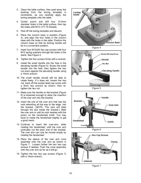
6. Place the column base in position (Figure<br />
4), and align the four holes in the column<br />
base with the holes in the table. Position the<br />
column base so that its locking handle will<br />
be in a convenient position.<br />
7. Insert four M12x50 hex cap screws with four<br />
M12 spring washers through the holes in the<br />
stand. See Figure 4.<br />
8. Tighten the four screws firmly with a wrench.<br />
9. Install the small handle into the hole in the<br />
elevating handle (Figure 5). Screw the small<br />
handle into the hole, then tighten the hex<br />
nut down against the elevating handle using<br />
a 14mm wrench.<br />
10. The small handle should still be able to<br />
rotate freely. If it does not, loosen the hex<br />
nut, back off the socket head cap screw with<br />
a 5mm hex wrench as shown, then retighten<br />
the hex nut.<br />
11. Make sure the handle on the bracket (Figure<br />
6) is loosened enough to allow the insertion<br />
of the over arm into the bracket.<br />
12. Insert the end of the over arm that has the<br />
rack extending all the way to the edge, into<br />
the bracket. (NOTE: The rack will slide<br />
through the slot inside the bracket.) Slide<br />
the over arm in until its rack meshes with the<br />
pinion on the handwheel shaft. You may<br />
have to rotate the handwheel slightly to get<br />
a good mesh.<br />
13. Continue to insert the over-arm, while<br />
rotating the handwheel, until the over arm<br />
protrudes out the back end of the bracket.<br />
The over arm can now be moved simply by<br />
rotating the handwheel.<br />
14. Place the sleeve of the over arm cone<br />
assembly onto the over arm as shown in<br />
Figure 7. Loosen further the two hex cap<br />
screws if needed. Push the cone assembly<br />
onto the over arm as far as it will go.<br />
15. Tighten the two hex cap screws (Figure 7)<br />
with a 14mm wrench.<br />
10<br />
Figure 4<br />
Figure 5<br />
Figure 6<br />
Figure 7