Owner's Manual - Roland
Owner's Manual - Roland
Owner's Manual - Roland

You also want an ePaper? Increase the reach of your titles
YUMPU automatically turns print PDFs into web optimized ePapers that Google loves.
WARNING: To reduce the risk of fire or electric shock, do not expose this apparatus to rain or moisture.<br />
CAUTION<br />
RISK OF ELECTRIC SHOCK<br />
DO NOT OPEN<br />
ATTENTION: RISQUE DE CHOC ELECTRIQUE NE PAS OUVRIR<br />
CAUTION: TO REDUCE THE RISK OF ELECTRIC SHOCK,<br />
DO NOT REMOVE COVER (OR BACK).<br />
NO USER-SERVICEABLE PARTS INSIDE.<br />
REFER SERVICING TO QUALIFIED SERVICE PERSONNEL.<br />
The lightning flash with arrowhead symbol, within an<br />
equilateral triangle, is intended to alert the user to the<br />
presence of uninsulated “dangerous voltage” within the<br />
product’s enclosure that may be of sufficient magnitude to<br />
constitute a risk of electric shock to persons.<br />
The exclamation point within an equilateral triangle is<br />
intended to alert the user to the presence of important<br />
operating and maintenance (servicing) instructions in the<br />
literature accompanying the product.<br />
INSTRUCTIONS PERTAINING TO A RISK OF FIRE, ELECTRIC SHOCK, OR INJURY TO PERSONS.<br />
IMPORTANT SAFETY INSTRUCTIONS<br />
SAVE THESE INSTRUCTIONS<br />
WARNING - When using electric products, basic precautions should always be followed, including the following:<br />
1. Read these instructions.<br />
2. Keep these instructions.<br />
3. Heed all warnings.<br />
4. Follow all instructions.<br />
5. Do not use this apparatus near water.<br />
6. Clean only with a dry cloth.<br />
7. Do not block any of the ventilation openings. Install in<br />
accordance with the manufacturers instructions.<br />
8. Do not install near any heat sources such as radiators,<br />
heat registers, stoves, or other apparatus (including<br />
amplifiers) that produce heat.<br />
9. Do not defeat the safety purpose of the polarized or<br />
grounding-type plug. A polarized plug has two blades with<br />
one wider than the other. A grounding type plug has two<br />
blades and a third grounding prong. The wide blade or the<br />
third prong are provided for your safety. If the provided plug<br />
does not fit into your outlet, consult an electrician for<br />
replacement of the obsolete outlet.<br />
WARNING:<br />
IMPORTANT:<br />
10. Protect the power cord from being walked on or pinched<br />
particularly at plugs, convenience receptacles, and the<br />
point where they exit from the apparatus.<br />
11. Only use attachments/accessories specified<br />
by the manufacturer.<br />
12. Unplug this apparatus during lightning storms or when<br />
unused for long periods of time.<br />
13. Refer all servicing to qualified service personnel. Servicing<br />
is required when the apparatus has been damaged in any<br />
way, such as power-supply cord or plug is damaged, liquid<br />
has been spilled or objects have fallen into the apparatus,<br />
the apparatus has been exposed to rain or moisture, does<br />
not operate normally, or has been dropped.<br />
For the U.K.<br />
THIS APPARATUS MUST BE EARTHED<br />
THE WIRES IN THIS MAINS LEAD ARE COLOURED IN ACCORDANCE WITH THE FOLLOWING CODE.<br />
GREEN-AND-YELLOW: EARTH, BLUE: NEUTRAL, BROWN: LIVE<br />
As the colours of the wires in the mains lead of this apparatus may not correspond with the coloured markings identifying<br />
the terminals in your plug, proceed as follows:<br />
The wire which is coloured GREEN-AND-YELLOW must be connected to the terminal in the plug which is marked by the<br />
letter E or by the safety earth symbol or coloured GREEN or GREEN-AND-YELLOW.<br />
The wire which is coloured BLUE must be connected to the terminal which is marked with the letter N or coloured BLACK.<br />
The wire which is coloured BROWN must be connected to the terminal which is marked with the letter L or coloured RED.<br />
Before using this unit, carefully read the sections entitled: “IMPORTANT SAFETY INSTRUCTIONS” (p. 2), “USING THE UNIT SAFELY” (p. 3), and “IMPORTANT<br />
NOTES” (p. 6). These sections provide important information concerning the proper operation of the unit. Additionally, in order to feel assured that you have<br />
gained a good grasp of every feature provided by your new unit, VS-700 Owner’s <strong>Manual</strong> should be read in its entirety. The manual should be saved and kept<br />
on hand as a convenient reference.<br />
Copyright © 2009 ROLAND CORPORATION<br />
All rights reserved. No part of this publication may be reproduced in any form without the written permission of ROLAND CORPORATION.
USING THE UNIT SAFELY<br />
Used for instructions intended to alert<br />
the user to the risk of death or severe<br />
injury should the unit be used<br />
improperly.<br />
Used for instructions intended to alert<br />
the user to the risk of injury or material<br />
damage should the unit be used<br />
improperly.<br />
* Material damage refers to damage or<br />
other adverse effects caused with<br />
respect to the home and all its<br />
furnishings, as well to domestic<br />
animals or pets.<br />
001-50<br />
• Connect mains plug of this model to a mains socket<br />
outlet with a protective earthing connection.<br />
......................................................................................................................<br />
003<br />
• Do not attempt to repair the unit, or replace parts<br />
within it (except when this manual provides specific<br />
instructions directing you to do so). Refer all servicing<br />
to your retailer, the nearest <strong>Roland</strong> Service Center, or<br />
an authorized <strong>Roland</strong> distributor, as listed on the<br />
“Information” (separate leaflet).<br />
......................................................................................................................<br />
004<br />
• Never install the unit in any of the following locations.<br />
• Subject to temperature extremes (e.g., direct<br />
sunlight in an enclosed vehicle, near a heating<br />
duct, on top of heat-generating equipment); or are<br />
• Damp (e.g., baths, washrooms, on wet floors); or are<br />
• Exposed to steam or smoke; or are<br />
• Subject to salt exposure; or are<br />
• Humid; or are<br />
• Exposed to rain; or are<br />
• Dusty or sandy; or are<br />
• Subject to high levels of vibration and shakiness.<br />
......................................................................................................................<br />
007<br />
• Make sure you always have the unit placed so it is level<br />
and sure to remain stable. Never place it on stands<br />
that could wobble, or on inclined surfaces.<br />
......................................................................................................................<br />
The symbol alerts the user to important instructions<br />
or warnings.The specific meaning of the symbol is<br />
determined by the design contained within the<br />
triangle. In the case of the symbol at left, it is used for<br />
general cautions, warnings, or alerts to danger.<br />
The symbol alerts the user to items that must never<br />
be carried out (are forbidden). The specific thing that<br />
must not be done is indicated by the design contained<br />
within the circle. In the case of the symbol at left, it<br />
means that the unit must never be disassembled.<br />
The ● symbol alerts the user to things that must be<br />
carried out. The specific thing that must be done is<br />
indicated by the design contained within the circle. In<br />
the case of the symbol at left, it means that the powercord<br />
plug must be unplugged from the outlet.<br />
008a<br />
• The unit should be connected to a power supply only<br />
of the type described in the operating instructions, or<br />
as marked on the rear side of the unit.<br />
Refer to p. 173 - for power requirements.<br />
Spec Page<br />
......................................................................................................................<br />
008e<br />
• Use only the attached power-supply cord. Also, the<br />
supplied power cord must not be used with any other<br />
device.<br />
......................................................................................................................<br />
009<br />
• Do not excessively twist or bend the power cord, nor<br />
place heavy objects on it. Doing so can damage the<br />
cord, producing severed elements and short circuits.<br />
Damaged cords are fire and shock hazards!<br />
......................................................................................................................<br />
010<br />
• This unit, either alone or in combination with an<br />
amplifier and headphones or speakers, may be<br />
capable of producing sound levels that could cause<br />
permanent hearing loss. Do not operate for a long<br />
period of time at a high volume level, or at a level that<br />
is uncomfortable. If you experience any hearing loss or<br />
ringing in the ears, you should immediately stop using<br />
the unit, and consult an audiologist.<br />
......................................................................................................................<br />
011<br />
• Do not allow any objects (e.g., flammable material,<br />
coins, pins); or liquids of any kind (water, soft drinks,<br />
etc.) to penetrate the unit.<br />
......................................................................................................................<br />
3<br />
Overview Connections VS-700C Console VS-700R I/O Fantom VS Appendix
USING THE UNIT SAFELY<br />
013<br />
• In households with small children, an adult should<br />
provide supervision until the child is capable of<br />
following all the rules essential for the safe operation<br />
of the unit.<br />
......................................................................................................................<br />
014<br />
• Protect the unit from strong impact.<br />
(Do not drop it!)<br />
......................................................................................................................<br />
015<br />
• Do not force the unit’s power-supply cord to share an<br />
outlet with an unreasonable number of other devices.<br />
Be especially careful when using extension cords—the<br />
total power used by all devices you have connected to<br />
the extension cord’s outlet must never exceed the<br />
power rating (watts/amperes) for the extension cord.<br />
Excessive loads can cause the insulation on the cord to<br />
heat up and eventually melt through.<br />
......................................................................................................................<br />
016<br />
• Before using the unit in a foreign country, consult with<br />
your retailer, the nearest <strong>Roland</strong> Service Center, or an<br />
authorized <strong>Roland</strong> distributor, as listed on the<br />
“Information” (separate leaflet).<br />
......................................................................................................................<br />
022a<br />
• Always turn the unit off and unplug the power cord<br />
before attempting installation of the circuit board<br />
(ARX series; p. 155).<br />
......................................................................................................................<br />
023<br />
• DO NOT play a CD-ROM/DVD-ROM disc on a<br />
conventional audio CD player. The resulting sound<br />
may be of a level that could cause permanent hearing<br />
loss. Damage to speakers or other system components<br />
may result.<br />
......................................................................................................................<br />
026<br />
• Do not put anything that contains water (e.g., flower<br />
vases) on this unit. Also, avoid the use of insecticides,<br />
perfumes, alcohol, nail polish, spray cans, etc., near the<br />
unit. Swiftly wipe away any liquid that spills on the<br />
unit using a dry, soft cloth.<br />
......................................................................................................................<br />
4<br />
101a<br />
• The unit should be located so that its location or<br />
position does not interfere with its proper ventilation.<br />
......................................................................................................................<br />
102b<br />
• Always grasp only the plug on the power-supply cord<br />
when plugging into, or unplugging from, an outlet or<br />
this unit.<br />
......................................................................................................................<br />
103a<br />
• At regular intervals, you should unplug the power<br />
plug and clean it by using a dry cloth to wipe all dust<br />
and other accumulations away from its prongs. Also,<br />
disconnect the power plug from the power outlet<br />
whenever the unit is to remain unused for an<br />
extended period of time. Any accumulation of dust<br />
between the power plug and the power outlet can<br />
result in poor insulation and lead to fire.<br />
......................................................................................................................<br />
104<br />
• Try to prevent cords and cables from becoming<br />
entangled. Also, all cords and cables should be placed<br />
so they are out of the reach of children.<br />
......................................................................................................................<br />
106<br />
• Never climb on top of, nor place heavy objects on the<br />
unit.<br />
......................................................................................................................<br />
107b<br />
• Never handle the power cord or its plugs with wet<br />
hands when plugging into, or unplugging from, an<br />
outlet or this unit.<br />
......................................................................................................................<br />
108a<br />
• Before moving the unit, disconnect the power plug<br />
from the outlet, and pull out all cords from external<br />
devices.<br />
......................................................................................................................<br />
109a<br />
• Before cleaning the unit, turn off the power and<br />
unplug the power cord from the outlet (p. 28).<br />
......................................................................................................................<br />
110a<br />
• Whenever you suspect the possibility of lightning in<br />
your area, pull the plug on the power cord out of the<br />
outlet.<br />
......................................................................................................................<br />
115a<br />
• Install only the specified circuit board (ARX series).<br />
Remove only the specified screws (p. 155).<br />
......................................................................................................................
118a<br />
• Should you remove screws of the ARX expansion<br />
board cover (p. 156) or the rackmount brackets (p.<br />
163), keep them in a safe place out of children's reach,<br />
so there is no chance of them being swallowed<br />
accidentally.<br />
......................................................................................................................<br />
120<br />
• Always turn the phantom power off when connecting<br />
any device other than condenser microphones that<br />
require phantom power. You risk causing damage if<br />
you mistakenly supply phantom power to dynamic<br />
microphones, audio playback devices, or other<br />
devices that don’t require such power. Be sure to<br />
check the specifications of any microphone you<br />
intend to use by referring to the manual that came<br />
with it.<br />
(This instrument’s phantom power: 48 V DC, 10mA Max)<br />
......................................................................................................................<br />
USING THE UNIT SAFELY<br />
5<br />
Overview Connections VS-700C Console VS-700R I/O Fantom VS Appendix
6<br />
IMPORTANT NOTES<br />
Power Supply<br />
301<br />
• Do not connect this unit to the same electrical outlet that is<br />
being used by an electrical appliance that is controlled by an<br />
inverter (such as a refrigerator, washing machine, microwave<br />
oven, or air conditioner), or that contains a motor. Depending<br />
on the way in which the electrical appliance is used, power<br />
supply noise may cause this unit to malfunction or may<br />
produce audible noise. If it is not practical to use a separate<br />
electrical outlet, connect a power supply noise filter between<br />
this unit and the electrical outlet.<br />
307<br />
• Before connecting this unit to other devices, turn off the<br />
power to all units. This will help prevent malfunctions and/or<br />
damage to speakers or other devices.<br />
308<br />
• Although the LCD and LEDs are switched off when the POWER<br />
switch is switched off, this does not mean that the unit has<br />
been completely disconnected from the source of power. If<br />
you need to turn off the power completely, first turn off the<br />
POWER switch, then unplug the power cord from the power<br />
outlet. For this reason, the outlet into which you choose to<br />
connect the power cord’s plug should be one that is within<br />
easy reach and readily accessible.<br />
Placement<br />
351<br />
• Using the unit near power amplifiers (or other equipment<br />
containing large power transformers) may induce hum. To<br />
alleviate the problem, change the orientation of this unit; or<br />
move it farther away from the source of interference.<br />
352a<br />
• This device may interfere with radio and television reception.<br />
Do not use this device in the vicinity of such receivers.<br />
352b<br />
• Noise may be produced if wireless communications devices,<br />
such as cell phones, are operated in the vicinity of this unit.<br />
Such noise could occur when receiving or initiating a call, or<br />
while conversing. Should you experience such problems, you<br />
should relocate such wireless devices so they are at a greater<br />
distance from this unit, or switch them off.<br />
354a<br />
• Do not expose the unit to direct sunlight, place it near devices<br />
that radiate heat, leave it inside an enclosed vehicle, or<br />
otherwise subject it to temperature extremes. Excessive heat<br />
can deform or discolor the unit.<br />
355b<br />
• When moved from one location to another where the<br />
temperature and/or humidity is very different, water droplets<br />
(condensation) may form inside the unit. Damage or<br />
malfunction may result if you attempt to use the unit in this<br />
condition. Therefore, before using the unit, you must allow it<br />
to stand for several hours, until the condensation has<br />
completely evaporated.<br />
360<br />
• Depending on the material and temperature of the surface on<br />
which you place the unit, its rubber feet may discolor or mar<br />
the surface.<br />
You can place a piece of felt or cloth under the rubber feet to<br />
prevent this from happening. If you do so, please make sure<br />
that the unit will not slip or move accidentally.<br />
Maintenance<br />
401a<br />
• For everyday cleaning, wipe the unit with a soft, dry cloth or<br />
one that has been slightly dampened with water. To remove<br />
stubborn dirt, use a cloth impregnated with a mild, nonabrasive<br />
detergent. Afterwards, be sure to wipe the unit<br />
thoroughly with a soft, dry cloth.<br />
402<br />
• Never use benzine, thinners, alcohol or solvents of any kind, to<br />
avoid the possibility of discoloration and/or deformation.<br />
Additional Precautions<br />
553<br />
• Use a reasonable amount of care when using the unit’s<br />
buttons, sliders, or other controls; and when using its jacks<br />
and connectors. Rough handling can lead to malfunctions.<br />
554<br />
• Never strike or apply strong pressure to the display.<br />
555<br />
• A small amount of noise may be heard from the display during<br />
normal operation.<br />
556<br />
• When connecting / disconnecting all cables, grasp the<br />
connector itself—never pull on the cable. This way you will<br />
avoid causing shorts, or damage to the cable’s internal<br />
elements.<br />
557<br />
• A small amount of heat will radiate from the unit during<br />
normal operation.<br />
558a<br />
• To avoid disturbing your neighbors, try to keep the unit’s<br />
volume at reasonable levels. You may prefer to use<br />
headphones, so you do not need to be concerned about those<br />
around you (especially when it is late at night).
559a<br />
• When you need to transport the unit, package it in the box<br />
(including padding) that it came in, if possible. Otherwise, you<br />
will need to use equivalent packaging materials.<br />
562<br />
• Some connection cables contain resistors. Do not use cables<br />
that incorporate resistors for connecting to this unit. The use<br />
of such cables can cause the sound level to be extremely low,<br />
or impossible to hear. For information on cable specifications,<br />
contact the manufacturer of the cable.<br />
Copyright<br />
851<br />
• Recording, duplication, distribution, sale, lease, performance,<br />
or broadcast of copyrighted material (musical works, visual<br />
works, broadcasts, live performances, etc.) belonging to a<br />
third party in part or in whole without the permission of the<br />
copyright owner is forbidden by law.<br />
852a<br />
• This product can be used to record or duplicate audio or visual<br />
material without being limited by certain technological copyprotection<br />
measures. This is due to the fact that this product is<br />
intended to be used for the purpose of producing original<br />
music or video material, and is therefore designed so that<br />
material that does not infringe copyrights belonging to others<br />
(for example, your own original works) can be recorded or<br />
duplicated freely.<br />
853<br />
• Do not use this unit for purposes that could infringe on a<br />
copyright held by a third party. We assume no responsibility<br />
whatsoever with regard to any infringements of third-party<br />
copyrights arising through your use of this unit.<br />
204<br />
IMPORTANT NOTES<br />
* Microsoft and Windows and Windows Vista are registered<br />
trademarks of Microsoft Corporation.<br />
206e<br />
* The screen shots in this document are used in compliance<br />
with the guidelines of the Microsoft Corporation.<br />
206j<br />
* Windows ® is known officially as: “Microsoft ® Windows ®<br />
operating system.”<br />
233<br />
* ASIO and VST are trademarks of Steinberg Media<br />
Technologies AG.<br />
ADD<br />
* MMP (Moore Microprocessor Portfolio) refers to a patent<br />
portfolio concerned with microprocessor architecture, which<br />
was developed by Technology Properties Limited (TPL).<br />
<strong>Roland</strong> has licensed this technology from the TPL Group.<br />
220<br />
* All product names mentioned in this document are<br />
trademarks or registered trademarks of their respective<br />
owners.<br />
7<br />
Overview Connections VS-700C Console VS-700R I/O Fantom VS Appendix
8<br />
Contents<br />
USING THE UNIT SAFELY............................................................................................................3<br />
IMPORTANT NOTES .....................................................................................................................6<br />
Overview of the VS-700 ......................................................... 13<br />
Main Features ............................................................................................................................. 14<br />
Main Features of the VS-700C Console ..................................................................................14<br />
Main Features of the VS-700R I/O.............................................................................................14<br />
Panel Descriptions .................................................................................................................... 15<br />
VS-700C Console.............................................................................................................................15<br />
Top Panel ......................................................................................................................15<br />
Rear Panel.....................................................................................................................18<br />
VS-700R I/O.......................................................................................................................................19<br />
Front Panel ...................................................................................................................19<br />
Rear Panel.....................................................................................................................21<br />
Top Panel ......................................................................................................................23<br />
Side Panel .....................................................................................................................24<br />
Connections............................................................................... 25<br />
Connections ................................................................................................................................ 26<br />
Turning the Power On ............................................................................................................. 28<br />
VS-700C Console...................................................................... 29<br />
Overview of the VS-700C Console....................................................................................... 30<br />
CHANNEL STRIP Section.......................................................................................................... 31<br />
Channel Fader.............................................................................................................32<br />
FLIP Mode .....................................................................................................................32<br />
Master Fader................................................................................................................32<br />
Adjusting the Touch Sensitivity of the Faders ................................................33<br />
Rotary Encoder (Knob).............................................................................................34<br />
Track Mute....................................................................................................................34<br />
Track Solo (SOLO) ......................................................................................................35<br />
Track Arm (ARM).........................................................................................................35<br />
Strip Select (SEL).........................................................................................................36
LED Level Meter..........................................................................................................37<br />
LCD Display ..................................................................................................................37<br />
ASSIGN Button.................................................................................................................................38<br />
How FLIP Mode Affects the [ASSIGN] Button ..................................................39<br />
Rude MUTE/Rude SOLO/Rude ARM Buttons........................................................................40<br />
AUTOMATION Buttons .................................................................................................................41<br />
FADER BANK Buttons....................................................................................................................42<br />
FADER VIEW Buttons (TRACK, BUS, MAIN, I/O CONTROL) ...............................................43<br />
I/O Control....................................................................................................................44<br />
Specifying the tracks and buses that can be controlled from the VS-700 console 45<br />
Locking a Channel Strip ...............................................................................................................46<br />
To Lock/Unlock a Channel Strip ...........................................................................46<br />
Locked Strip WAI Indication...................................................................................47<br />
Time Display................................................................................................................................ 48<br />
CHANNEL STRIP CONTROL Section (EQ, SEND and ACT)............................................ 49<br />
LCD Display ..................................................................................................................51<br />
EQ Mode........................................................................................................................51<br />
SEND Mode ..................................................................................................................52<br />
ACT Mode .....................................................................................................................53<br />
Transport Section ...................................................................................................................... 54<br />
Starting/Stopping Playback With a Foot Switch ............................................55<br />
PROJECT Section........................................................................................................................ 56<br />
JOG/SHUTTLE/CURSOR Section ........................................................................................... 57<br />
Transport Mode (Default) .......................................................................................58<br />
Scroll Mode ..................................................................................................................59<br />
Zoom Mode .................................................................................................................60<br />
Select Mode .................................................................................................................61<br />
Edit Mode......................................................................................................................62<br />
Scrub Play Mode.........................................................................................................63<br />
ACCESS PANEL Section (Assignable Buttons)................................................................. 64<br />
Mapping Assignable ACCESS PANEL Buttons.................................................66<br />
Modifier Buttons ........................................................................................................67<br />
SURROUND Section.................................................................................................................. 68<br />
T-Bar Section ............................................................................................................................... 69<br />
AUDIO OUTPUT Section.......................................................................................................... 70<br />
RECORD/EDIT Section.............................................................................................................. 71<br />
Controlling Plug-ins from the VS-700C Console ............................................................ 74<br />
Contents<br />
9<br />
Overview Connections VS-700C Console VS-700R I/O Fantom VS Appendix
Contents<br />
10<br />
VS-700R I/O ................................................................................ 77<br />
Connecting Recording Equipment ..................................................................................... 78<br />
Connections to the Analog Jacks .............................................................................................78<br />
Connections to the Digital Connectors..................................................................................79<br />
Switching the Sampling Rate................................................................................................ 80<br />
Setting SONAR’s Sampling Rate................................................................................................81<br />
Audio Clock Source................................................................................................................... 82<br />
Phantom Power ......................................................................................................................... 83<br />
Preamp Parameters .................................................................................................................. 84<br />
Compressor Parameters.......................................................................................................... 85<br />
Direct Monitor Mixer ................................................................................................................ 86<br />
Fantom VS<br />
(Synthesizer) .............................................................................. 87<br />
Inserting the Fantom VS Plug-In.......................................................................................... 88<br />
Fantom VS Editor (Selecting a Sound)............................................................................... 89<br />
Fantom VS Editor (Editing a Sound) ................................................................................... 90<br />
To select a parameter type.....................................................................................90<br />
To edit parameter values ........................................................................................90<br />
To initialize a parameter value..............................................................................90<br />
Overview of the Fantom VS................................................................................................... 91<br />
How the Fantom VS is Organized.............................................................................................91<br />
Classification of Fantom VS Sound Types.........................................................91<br />
About Simultaneous Polyphony ..........................................................................93<br />
About Memory ................................................................................................................................94<br />
Temporary Memory ..................................................................................................94<br />
Non-Rewritable Memory.........................................................................................94<br />
About the Onboard Effects.........................................................................................................95<br />
Effect Types..................................................................................................................95<br />
How Effects Units Work ...........................................................................................95<br />
Creating a Patch......................................................................................................................... 96<br />
How to Make Patch Settings ......................................................................................................96<br />
Functions of Patch Parameters..................................................................................................96<br />
Settings Common to the Entire Patch (GENERAL).........................................96
Changing How a Tone Is Sounded (TMT)....................................................... 101<br />
Modifying Waveforms (WG)................................................................................ 105<br />
Modifying the Brightness of a Sound with a Filter (TVF/TVF Env)......... 109<br />
Adjusting the Volume (TVA/TVA Env) ............................................................. 113<br />
Output Settings ....................................................................................................... 116<br />
Modulating Sounds (LFO1/2/Step LFO) ......................................................... 117<br />
Controller-related settings (CTRL) .................................................................... 120<br />
Matrix Control Settings (Matrix Ctrl1–4)......................................................... 121<br />
Creating a Rhythm Set...........................................................................................................125<br />
Functions of Rhythm Set Parameters................................................................................... 125<br />
Making Settings Common to the Entire Rhythm Set (GENERAL).......... 125<br />
Modifying Waveforms (WG)................................................................................ 127<br />
Changing How a Rhythm Tone is Sounded (WMT) .................................... 128<br />
Modifying Pitch (PCH/PCH Env) ........................................................................ 129<br />
Modifying the Brightness of a Sound with a Filter (TVF/TVF Env)......... 131<br />
Adjusting the Volume (TVA/TVA Env) ............................................................. 133<br />
Output Settings ....................................................................................................... 135<br />
Creating a Performance ........................................................................................................136<br />
Adjusting the Parameters of Each Part................................................................................ 136<br />
Parameter List ......................................................................................................... 136<br />
Scale Tune settings ..................................................................................................................... 141<br />
Parameter List .......................................................................................................... 141<br />
MIDI-related settings.................................................................................................................. 142<br />
Parameter List .......................................................................................................... 142<br />
Adding Effects ..........................................................................................................................144<br />
Turning Effects On and Off....................................................................................................... 144<br />
Applying Effects........................................................................................................................... 145<br />
Signal Flow Diagram (Routing).......................................................................... 145<br />
Functions of Effect Parameters.......................................................................... 146<br />
Specifying the Effect Source............................................................................... 149<br />
Specifying the multi-effect structure (MFX Structure) .............................. 150<br />
System Settings........................................................................................................................151<br />
Functions of System Parameters ........................................................................................... 151<br />
Contents<br />
11<br />
Overview Connections VS-700C Console VS-700R I/O Fantom VS Appendix
Contents<br />
12<br />
Appendix ..................................................................................153<br />
VS-700R Block Diagram.........................................................................................................154<br />
Installing the ARX Expansion Board .................................................................................155<br />
Port settings (MIDI input and audio output)..................................................................... 155<br />
Cautions When Installing an Expansion Board................................................................. 155<br />
How to Install an Expansion Board ....................................................................................... 156<br />
Removing an Expansion Board .............................................................................................. 158<br />
Installation de la carte d’expansion..................................................................................159<br />
Precautions a prendre lors de l’installation d’une carte d’expansion ...................... 159<br />
Installation d’une carte d’expansion .................................................................................... 160<br />
Retrait d’une carte d’expansion ............................................................................................. 162<br />
Attaching the Rackmount Brackets ..................................................................................163<br />
Using only the VS-700C Console (Standalone Mode) ................................................164<br />
Using only the VS-700R I/O..................................................................................................165<br />
Connecting Two VS-700R I/O Units ..................................................................................166<br />
Connecting an EDIROL DV-7DL (Video Control) ..........................................................168<br />
Connecting the EDIROL DV-7DL and VS-700C............................................. 168<br />
To Enable Video Control....................................................................................... 168<br />
About V-LINK.............................................................................................................................169<br />
Troubleshooting ......................................................................................................................171<br />
Problems with the VS-700R Unit............................................................................................ 171<br />
Problems with the VS-700C Unit ........................................................................................... 171<br />
Specifications............................................................................................................................172<br />
Index ............................................................................................................................................175<br />
Index (Fantom VS)...................................................................................................................179
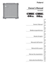
Overview of the VS-700<br />
13
fig.panel-vs-700.eps<br />
14<br />
Main Features<br />
Main Features of the VS-700C Console<br />
fig.panel-vs-700r.eps<br />
• Control of mix and plug-in parameters with real-time visual feedback<br />
• Touch-sensitive motorized faders<br />
• Control over SONAR, plug-in effects and soft synths<br />
• Many buttons to trigger SONAR commands plus 16 assignable buttons<br />
• Multiple modifier buttons to extend the functionality of other controls<br />
• Tape-style transport controls<br />
• Jog/shuttle wheel with cursor-style buttons for scrubbing, editing, zooming and scrolling<br />
• Surround joystick panner<br />
• Meter displays with track names and parameters<br />
Main Features of the VS-700R I/O<br />
• 19-in/24-out USB 2.0 audio interface<br />
• 24-bit 192 kHz high quality audio<br />
• Eight channels of preamps/compressors built-in<br />
• Built-in Fantom VS synthesizer<br />
• Single slot for ARX series expansion boards
Panel Descriptions<br />
VS-700C Console<br />
Top Panel<br />
fig.panel-vs-700c-top.eps<br />
D<br />
E<br />
A. LCD Display<br />
B. T-Bar<br />
A<br />
The VS-700C features three 2-line LCD displays. The left LCD display shows information about the CHANNEL STRIP<br />
CONTROL section and the other two LCD displays show information about the channel strips.<br />
➔ “LCD Display” (p. 37), (p. 51)<br />
The T-Bar lets you control the Front-Rear Balance parameter in the surround panner, an ACT parameter or the X-Ray<br />
opacity.<br />
➔ “T-Bar Section” (p. 69)<br />
F G H<br />
B C<br />
M N<br />
I<br />
J<br />
K<br />
L<br />
15<br />
Overview Connections VS-700C Console VS-700R I/O Fantom VS Appendix
Panel Descriptions<br />
C. Time Display<br />
16<br />
The VS-700C Console displays the project’s current Now time in the top right corner. You can switch the display<br />
between SMPTE and Bars|Beats time by pressing the [TIME CODE] button. The default view is Bars|Beats.<br />
➔ “Time Display” (p. 48)<br />
D. CHANNEL STRIP CONTROL Section<br />
The CHANNEL STRIP CONTROL section lets you control EQ and SEND parameters for the selected channel strip, as<br />
well as ACT parameters for the track, bus, effect plug-in or soft synth that has focus in SONAR.<br />
There are 12 rotary encoders and 4 buttons to control EQ, SEND and ACT parameters.<br />
➔ “CHANNEL STRIP CONTROL Section (EQ, SEND and ACT)” (p. 49)<br />
E. ACCESS PANEL Section<br />
F. Channel Strips<br />
The ACCESS PANEL section provides 16 assignable buttons that you can configure to control different functions in<br />
SONAR. There are also 4 modifier buttons that are used to extend the functionality of other VS-700 hardware<br />
controls. The modifier buttons are not assignable.<br />
➔ “ACCESS PANEL Section (Assignable Buttons)” (p. 64)<br />
The Channel Strip section provides eight motorized fader strips with identical controls. You use the channel strips to<br />
control up to eight tracks or buses at a time and you can easily switch between different banks of tracks or buses.<br />
➔ “CHANNEL STRIP Section” (p. 31)<br />
G. RECORD/EDIT Section<br />
H. Transport Section<br />
The RECORD/EDIT section lets you control punch-recording and looping, select clips or edit regions, and insert or<br />
move markers.<br />
➔ “RECORD/EDIT Section” (p. 71)<br />
The transport section provides standard control of RTZ (return to zero), Rewind, Fast Forward, Go to end, Stop, Play<br />
and Record.<br />
➔ “Transport Section” (p. 54)<br />
I. AUDIO OUTPUT Section<br />
The AUDIO OUTPUT section lets you control the volume of the MONITOR output and each headphone output. You<br />
can also mute the MONITOR output and assign each headphone to monitor the MAIN/SUB output.<br />
➔ “AUDIO OUTPUT Section” (p. 70)
J. SURROUND Section<br />
K. PROJECT Section<br />
L. Jog/Shuttle Wheel<br />
The SURROUND section lets you control surround bus parameters on the selected channel strip.<br />
➔ “SURROUND Section” (p. 68)<br />
Panel Descriptions<br />
The PROJECT sections provides convenient access to frequently used commands that normally require a keyboard or<br />
mouse, such as Save, Undo/Redo, OK/ENTER and Cancel.<br />
➔ “PROJECT Section” (p. 56)<br />
The VS-700C Console jog/shuttle is a combo wheel with cursor buttons, which lets you perform edit, zoom, scroll and<br />
select operations.<br />
➔ “JOG/SHUTTLE/CURSOR Section” (p. 57)<br />
M. AUX IN Jack (Front Panel)<br />
This is a mic/guitar input jack located on the front panel of the console. It supports mic input when the switch is at<br />
“NORMAL,” or guitar input when the switch is at [Hi-Z]. Use the SENS knob to adjust the input level. The input signal is<br />
output directly to the “VS-700 AUX” port of the audio driver.<br />
➔ “Connections to the Analog Jacks” (p. 78)<br />
N. PHONES Jacks (Front Panel)<br />
These are two headphone jacks located on the front panel of the console. They monitor either the MAIN port or SUB<br />
port, and each has a switch on the console to select the signal that it will monitor. The volume can be adjusted<br />
independently for each jack.<br />
➔ “AUDIO OUTPUT Section” (p. 70)<br />
17<br />
Overview Connections VS-700C Console VS-700R I/O Fantom VS Appendix
Panel Descriptions<br />
Rear Panel<br />
fig.panel-vs-700c-rear.eps<br />
A. TO I/O Connector<br />
B. USB Connector<br />
18<br />
Use the dedicated cable to connect the VS-700C Console to the VS-700R I/O unit. Do not use any cable other than the<br />
dedicated cable.<br />
➔ “Connecting Your Computer and Sound Reinforcement Equipment” (p. 27)<br />
By connecting the USB connector of the console directly to your computer (without using the VS-700R I/O unit), you<br />
can use the console as a control surface.<br />
➔ “Using only the VS-700C Console (Standalone Mode)” (p. 164)<br />
C. SETTING DIP Switches<br />
D. FOOT SW Jacks<br />
Change the settings of these switches if you have connected the console directly to your computer (without using<br />
the VS-700R I/O unit).<br />
E. LCD CONTRAST Knob<br />
F. AC Inlet<br />
G. POWER ON Switch<br />
➔ “Using only the VS-700C Console (Standalone Mode)” (p. 164)<br />
Here you can connect two foot switches.<br />
➔ “Starting/Stopping Playback With a Foot Switch” (p. 55)<br />
This adjusts the brightness of the LCD display.<br />
Connect the included power cord to this inlet.<br />
➔ “Connecting the Power Cord” (p. 26)<br />
Press to turn the power on/off.<br />
➔ “Turning the Power On” (p. 28)<br />
A B C D E F G
VS-700R I/O<br />
Front Panel<br />
fig.panel-vs-700r-front.eps<br />
C<br />
D<br />
E<br />
A. USB Indicator<br />
B. CONSOLE Indicator<br />
C. MIDI IN Indicator<br />
This will light when the console is connected via USB to your computer.<br />
➔ “If the USB indicator of the VS-700R I/O unit isn’t lit” (p. 28)<br />
Panel Descriptions<br />
This will light when the VS-700C console is connected via the dedicated cable and has been detected. If the cable is<br />
connected but the console has not been detected, this will blink.<br />
➔ “If the I/O indicator of the VS-700C console or the CONSOLE indicator of the VS-700R I/O unit is blinking”<br />
(p. 28)<br />
This will light when MIDI messages are received at the MIDI IN connector.<br />
MIDI OUT Indicator<br />
D. DIGITAL IN Indicators<br />
A B G<br />
This will light when MIDI messages are transmitted from the MIDI OUT connector.<br />
These will light when audio signals are input to DIGITAL IN 1 or 2.<br />
DIGITAL OUT Indicators<br />
F H I J K<br />
These will light when audio signals are output from DIGITAL OUT 1 or 2.<br />
19<br />
Overview Connections VS-700C Console VS-700R I/O Fantom VS Appendix
Panel Descriptions<br />
E. SAMPLE RATE Knob<br />
F. SYNC Indicator<br />
G. INPUT Indicators<br />
20<br />
This specifies the sample rate. In order for this setting to be reflected by the system, you must cycle the power to the<br />
VS-700R. If you need to synchronize with another digital device, you must first set this knob to the same sample rate<br />
as the master device.<br />
➔ “Switching the Sampling Rate” (p. 80)<br />
This indicates the audio clock status.<br />
➔ “Audio Clock Source” (p. 82)<br />
These indicate the input levels from the INPUT connectors and AUX connectors.<br />
If PEAK has lit, the sound has distorted.<br />
H. MONITOR MAIN Indicators<br />
If the cooling fan (p. 24) has stopped turning because of a malfunction, all indicators will blink. For details,<br />
refer to “Troubleshooting” (p. 171).<br />
These will light when audio signals are output from MONITOR MAIN.<br />
MONITOR SUB Indicators<br />
These will light when audio signals are output from MONITOR SUB.<br />
I. OUTPUT 1–10 Indicators<br />
J. POWER ON Switch<br />
K. Rackmount brackets<br />
These will light when audio signals are output from OUTPUT 1–10.<br />
Press this to turn the power on/off.<br />
➔ “Turning the Power On” (p. 28)<br />
If you want to install the system in a 19” rack, attach the included rackmount brackets.<br />
➔ “Attaching the Rackmount Brackets” (p. 163)
Rear Panel<br />
fig.panel-vs-700r-rear.eps<br />
A. TO CONSOLE Connector<br />
B. AC Inlet<br />
C. MIDI IN Connector<br />
Panel Descriptions<br />
Use the dedicated cable to connect this to the VS-700C console. Do not use any cable other than the dedicated cable.<br />
➔ “Connecting Your Computer and Sound Reinforcement Equipment” (p. 27)<br />
Connect the included power cord to this inlet.<br />
➔ “Connecting the Power Cord” (p. 26)<br />
* For details on the power supply and power consumption, refer to “Specifications” (p. 172).<br />
This is a MIDI input connector. You can connect your MIDI keyboard or MIDI controller here. This can also be used as<br />
an MTC input. In the driver, this will appear as “IO MIDI (VS-700).”<br />
MIDI OUT Connector<br />
D. USB Connector<br />
A C D E F G H I<br />
B J<br />
This is a MIDI output connector. You can connect an external MIDI sound module here. In the driver, this will appear<br />
as “IO MIDI (VS-700).”<br />
Connect this to a computer that supports USB 2.0.<br />
➔ “Connecting Your Computer and Sound Reinforcement Equipment” (p. 27)<br />
At first, before connecting anything to this connector, you must install the driver as described in “Getting<br />
Started” (separate document). After the driver has been installed and connections have been completed<br />
correctly, the USB indicator will light. If the USB indicator isn’t lit, the driver has not been installed correctly.<br />
Refer to the troubleshooting section of “Getting Started,” and install the driver once again.<br />
21<br />
Overview Connections VS-700C Console VS-700R I/O Fantom VS Appendix
Panel Descriptions<br />
E. DIGITAL 2 OUT Connector<br />
22<br />
This is an ADAT output connector. You can connect it to an ADAT device and output up to eight channels of audio.<br />
DIGITAL 2 IN Connector<br />
This is an ADAT input connector. It allows up to eight channels of input. The input signals are output directly to the<br />
“VS-700 IN DIGITAL2 1-2” – “VS-700 IN DIGITAL2 7-8” ports of the audio driver.<br />
➔ “Connections to the Digital Connectors” (p. 79)<br />
F. DIGITAL 1 AES/EBU OUT Connector<br />
This is an AES/EBU format two-channel (stereo) digital output. The same signal is also output to the COAXIAL OUT<br />
connector. This will output the signal of the audio driver’s “VS-700 OUT DIGITAL1” port.<br />
DIGITAL 1 AES/EBU IN Connector<br />
This is an AES/EBU format two-channel (stereo) digital input. This is switched with the COAXIAL IN (S/PDIF)<br />
connector. The input signal is output directly to the audio driver’s “VS-700 IN DIGITAL1” port.<br />
➔ “Connections to the Digital Connectors” (p. 79)<br />
DIGITAL 1 COAXIAL OUT Connector<br />
This is an S/PDIF format two-channel (stereo) digital output. The same signal is also output to the AES/EBU connector.<br />
This will output the signal of the audio driver’s “VS-700 OUT DIGITAL1” port.<br />
DIGITAL 1 COAXIAL IN Connector<br />
This is an S/PDIF format two-channel (stereo) digital input. This is switched with the AES/EBU connector. The input<br />
signal is output directly to the audio driver’s “VS-700 IN DIGITAL1” port.<br />
➔ “Connections to the Digital Connectors” (p. 79)<br />
G. WORDCLOCK IN Connector<br />
This is a WORDCLOCK input connector.<br />
WORDCLOCK OUT Connector<br />
For details on checking and selecting the clock source, refer to “Audio Clock Source” (p. 82).<br />
This is a WORDCLOCK output connector. It outputs a clock at all times.<br />
H. OUTPUT 1–10 Jacks<br />
These are ten channels of audio output connectors. They allow a broad range of connections, such as for multioutput<br />
in a surround system, or as sends for outboard effects. These are balanced outputs. They output the signals of<br />
the audio driver’s “1-2 (VS-700)” – “VS-700 OUT 9-10” ports.
I. MONITOR MAIN Jacks<br />
Panel Descriptions<br />
These are the main monitor output jacks. They are balanced outputs. They output the signals of the audio driver’s<br />
“VS-700 MAIN” port.<br />
MONITOR SUB Jacks<br />
J. INPUT 1–8 Jacks<br />
Top Panel<br />
fig.panel-vs-700r-top.eps<br />
These are sub-monitor output jacks. They provide balanced or unbalanced output. They output the signals of the<br />
audio driver’s “VS-700 SUB” port.<br />
These are eight channels of analog audio input. Both XLR type (balanced) and phone type (balanced or unbalanced)<br />
input jacks are provided. A mic preamp and compressor are provided on each channel. Phantom power is provided<br />
to the XLR jacks (switchable for each channel). The input signals are output directly to the audio driver’s “VS-700 IN 1-<br />
2” – “VS-700 IN 7-8” ports.<br />
* The XLR jacks and phone jacks cannot be connected simultaneously.<br />
➔ “Connections to the Analog Jacks” (p. 78)<br />
A. ARX Expansion Board Slot<br />
Here you can install an ARX expansion board.<br />
➔ “Installing the ARX Expansion Board” (p. 155)<br />
A<br />
23<br />
Overview Connections VS-700C Console VS-700R I/O Fantom VS Appendix
Panel Descriptions<br />
Side Panel<br />
fig.panel-vs-700r-side.eps<br />
A. Rackmount Brackets<br />
24<br />
If you want to install the system in a 19” rack, attach the included rackmount brackets.<br />
➔ “Attaching the Rackmount Brackets” (p. 163)<br />
B. Cooling Fan Intake Vent<br />
C. Cooling Fan Exhaust Vent<br />
A C<br />
B A<br />
The VS-700R contains a cooling fan that prevents internal overheating. External air is drawn in through the intake<br />
vent, then is expelled from the exhaust vent, while carrying along with it the heat that has accumulated inside the<br />
unit.<br />
Do not block the cooling fan intake vent or exhaust vent. Doing so will cause the internal temperature to rise,<br />
possibly causing heat-related malfunctions.<br />
If you install the system in a 19" rack, you must leave at least 1 cm of space outside the intake vent and exhaust<br />
vent.
Connections<br />
25
26<br />
Connections<br />
Connecting the Power Cord<br />
fig.VS-700-connect04-e.eps<br />
• Connect the power cord.<br />
Before connecting the VS-700C and VS-700R to your computer, you must install the VS-700 driver<br />
in your computer as described in “Getting Started” (separate document). The VS-700C and<br />
VS-700R will not operate correctly unless the driver is installed in your computer.<br />
Power Cord<br />
VS-700C Rear Panel<br />
VS-700R Rear Panel<br />
Power Cord<br />
to Power Outlet<br />
to Power Outlet
Connecting Your Computer and Sound Reinforcement Equipment<br />
fig.basic-e.eps<br />
921<br />
• Use the included dedicated cable to connect the VS-700R and VS-700C.<br />
• Use a USB cable to connect the VS-700R to your computer.<br />
• Connect your headphones, speakers, or other device to the VS-700.<br />
* This package does not include sound reinforcement equipment such as headphones or speakers.<br />
VS-700C<br />
USB cable (included)<br />
Dedicated connection<br />
cable (included)<br />
Monitor (sub)<br />
amplified speakers<br />
Monitor (main)<br />
amplified speakers<br />
VS-700R Rear Panel<br />
Stereo<br />
Headphones 1<br />
Stereo<br />
Headphones 2<br />
Connections<br />
The VS-700 may not be recognized correctly if you’re using a USB hub. In this case, connect it directly to a<br />
USB port on your computer.<br />
To prevent malfunction and/or damage to speakers or other devices, always turn down the volume, and turn<br />
off the power on all devices before making any connections.<br />
27<br />
Overview Connections VS-700C Console VS-700R I/O Fantom VS Appendix
941<br />
945<br />
28<br />
Turning the Power On<br />
Once the connections have been completed (p. 26), turn on power to your various devices in the order<br />
specified. By turning on devices in the wrong order, you risk causing malfunction and/or damage to speakers<br />
and other devices.<br />
If you need to turn off the power completely, first turn off the POWER switch, then unplug the power cord from<br />
the power outlet. Refer to “Power Supply” (p. 6).<br />
1. Minimize the VS-700C’s [AUDIO OUTPUT]<br />
knobs (three locations).<br />
2. Start up your computer.<br />
3. Turn on the power switch of the VS-700C.<br />
4. Turn on the power switch of the VS-700R.<br />
5. Turn on the power switch of your monitor speakers.<br />
VS-700C Rear Panel<br />
VS-700R Front Panel<br />
VS-700C Top Panel<br />
Power On<br />
Power On<br />
Due to a circuitry-protection feature, the VS-700R requires a few moments after power-up before it is ready<br />
for normal operation. If the connections are correct, the VS-700R’s USB indicator will light.<br />
If the USB indicator of the VS-700R I/O unit isn’t lit<br />
If the USB indicator of the VS-700R isn’t lit, the driver has not been installed correctly. Refer to the<br />
“Troubleshooting” chapter in “Getting Started.”<br />
If the I/O indicator of the VS-700C console or the CONSOLE indicator of the VS-700R I/O unit is blinking<br />
Check the following points.<br />
• Are the VS-700C and VS-700R powered up?<br />
• Are the VS-700C and VS-700R correctly connected via the dedicated cable?<br />
• Is the VS-700 R I/O unit connected to your computer via a USB cable, and is the USB indicator of the<br />
VS-700R I/O unit lit?
VS-700C Console<br />
29
30<br />
Overview of the VS-700C Console<br />
fig.panel-VS-700c-top.eps<br />
The VS-700C Console consist of different sections that are used to control SONAR, including:<br />
• Nine touch sensitive motorized faders<br />
• User definable buttons to map via ACT<br />
• Dedicated section for controlling plug-ins and track/bus parameters<br />
• Jog/Shuttle wheel<br />
• Transport controls<br />
• Surround joystick panner<br />
D<br />
E<br />
A. LCD display (p. 37, p. 51)<br />
B. T-bar (p. 69)<br />
A<br />
C. Time display (p. 48)<br />
D. CHANNEL STRIP CONTROL section (p. 49)<br />
E. ACCESS PANEL section (p. 64)<br />
F. Channel strips (p. 31)<br />
G. RECORD/EDIT section (p. 71)<br />
H. Transport section (p. 54)<br />
I. AUDIO OUTPUT section (p. 70)<br />
J. SURROUND section (p. 68)<br />
K. PROJECT section (p. 56)<br />
L. Jog/Shuttle wheel (p. 57)<br />
M. AUX IN Jack (Front Panel) (p. 78)<br />
N. PHONES Jack (Front Panel) (p. 70)<br />
F G H<br />
B C<br />
M N<br />
I<br />
J<br />
K<br />
L
fig.2.eps<br />
CHANNEL STRIP Section<br />
The Channel Strip section provides eight touch sensitive motorized fader strips with identical controls. You use the<br />
channel strips to control up to eight tracks or buses at a time and you can easily switch between different banks of<br />
tracks or buses (refer to “FADER BANK Buttons” (p. 42)). That is, although there are only eight physical channel<br />
strips, you can switch them to control an unlimited number of tracks and buses in your project. The channel strips<br />
always show the status of the current set of eight channels.<br />
The Channel Strip section also provides a single motorized Master fader, which is used to control the level of the<br />
master bus.<br />
You use the [FADER BANK] and [FADER VIEW] buttons to assign tracks and buses to the channel strips (refer to<br />
“FADER BANK Buttons” (p. 42) and “FADER VIEW Buttons (TRACK, BUS, MAIN, I/O CONTROL)” (p. 43)). The<br />
assigned channel strip names are displayed on the LCD displays.<br />
A. LCD display (p. 37)<br />
B. Rotary encoder (p. 34)<br />
C. [MUTE] button (p. 34)<br />
D. [SOLO] button (p. 35)<br />
E. [ARM] button (arm for recording) (p. 35)<br />
F. [SEL] button (Select) (p. 36)<br />
G. LED level meter (p. 37)<br />
H. Channel fader (p. 32)<br />
A<br />
B C<br />
D EF<br />
G<br />
H<br />
31<br />
Overview Connections VS-700C Console VS-700R I/O Fantom VS Appendix
CHANNEL STRIP Section<br />
Channel Fader<br />
32<br />
Use the touch sensitive motorized faders to control levels of audio tracks, MIDI tracks and buses.<br />
When tracks/buses are armed for automation recording, the faders allow you to record automation data by<br />
touching/releasing the faders.<br />
For more information about automation recording, refer to “Rude MUTE/Rude SOLO/Rude ARM Buttons” (p.<br />
40).<br />
During playback, the motorized faders move in response to existing automation data.<br />
To Revert a Fader to Its Previous Value<br />
FLIP Mode<br />
fig.2-2.eps<br />
Master Fader<br />
The motorized faders are very quiet, but there may be situations when you want total silence when mixing<br />
a soft piece of music or recording with a microphone near the VS-700C Console. To disable the fader<br />
motors, press [COMMAND]+[I/O] buttons to open the VS-700 property page, then click Disable Fader<br />
Movements.<br />
Hold the [COMMAND] modifier button and touch/move a fader.<br />
The top row on the LCD display shows “Revert”. After 1/2 second, the parameter reverts to its previous value and the<br />
LCD display reverts to its previous display mode.<br />
When FLIP mode is enabled, the functions of the rotary encoders and faders are swapped, allowing you to use the<br />
faders for more detailed control of the currently assigned encoder function (refer to “ASSIGN Button” (p. 38)).<br />
By default, the fader value is only displayed on the LCD display when you move the fader. To toggle between always<br />
showing rotary encoder values or fader values on the LCD display, press [SHIFT]+[FLIP] buttons.<br />
The master fader controls the first available bus in your project, however it can be assigned to control the level of any<br />
stereo or surround bus in SONAR.<br />
To Assign a Bus to the Master Fader<br />
Drag the WAI strip in SONAR to assign a bus to the master fader. For more information about the WAI strip, see the<br />
SONAR online Help.
Adjusting the Touch Sensitivity of the Faders<br />
fig.7a.eps_50<br />
CHANNEL STRIP Section<br />
Depending on the conditions in which you use the VS-700, the touch sensitivity of the faders may not<br />
work as you expect, or the motor may operate incorrectly when you’re operating the fader. If this occurs,<br />
adjust the touch sensitivity as follows.<br />
1. Close SONAR.<br />
2. While holding down the [SHIFT] button and [CTRL] button, press the [MUTE] button of<br />
the audio output section.<br />
The current sensitivity setting will be shown in the LCD display, and you’ll be in sensitivity adjustment<br />
mode.<br />
A<br />
Fader Touch Sensitivity:100<br />
OFF OFF OFF OFF<br />
A. Fader Touch Sensitivity (0–127)<br />
Higher values will increase the touch sensitivity; lower values will make it less responsive. At a<br />
setting of 0, touch sensitivity will be disabled.<br />
B. Touch sensitivity monitor<br />
This will indicate “ON” if touch sensitivity activates when you touch the fader, and will return to<br />
“OFF” when you remove your finger.<br />
3. Turn the jog wheel to adjust “Fader Touch Sensitivity” in a range of 0–127.<br />
Adjust this setting so that the touch sensitivity monitor indication in the LCD display changes from<br />
“OFF” to “ON” when you touch each fader. Increase the value if the indication fails to turn “ON” when<br />
you touch a fader; decrease the value if the indication turns “ON” when you merely bring your finger<br />
near the fader.<br />
The “Fader Touch Sensitivity” setting is common to all faders.<br />
4. When you’ve finished making settings, hold down the [SHIFT] button and [CTRL]<br />
button and press the [MUTE] button of the audio output section.<br />
You’ll exit sensitivity adjustment mode, and return to the previous screen.<br />
B<br />
Rotate JOG to adjust sensitivity<br />
OFF OFF OFF OFF OFF<br />
33<br />
Overview Connections VS-700C Console VS-700R I/O Fantom VS Appendix
CHANNEL STRIP Section<br />
Rotary Encoder (Knob)<br />
34<br />
The rotary encoders work in conjunction with the [ASSIGN] button to allow tactile control over various track, bus and<br />
main parameters. All eight rotary encoders always control the same parameter type across different tracks/buses.<br />
The rotary encoders control pan by default, but can be configured to control other channel parameters by pressing<br />
the [ASSIGN] button. For details on the [ASSIGN] button, refer to “ASSIGN Button” (p. 38).<br />
You can push on the top of the rotary encoder to reset the parameter to its default and/or unity setting (C for pan<br />
and 0 dB for gains).<br />
When FLIP mode is enabled, the functions of the rotary encoders and faders are swapped, allowing you to use the<br />
faders for more detailed control of the currently assigned encoder function.<br />
To Revert a Rotary Encoder to Its Previous Value<br />
Track Mute<br />
Hold the [COMMAND] modifier button and press/turn a rotary encoder.<br />
The top row on the LCD display shows “Revert.” After 1/2 second, the parameter reverts to its previous value and the<br />
LCD display reverts to its previous display mode.<br />
Use the [MUTE] button to mute/unmute the assigned track or bus. When the channel is muted, the [MUTE] button is<br />
lit.<br />
When one or more channels are muted, the [Rude MUTE] button is lit as a convenient reminder. You can press the<br />
[Rude MUTE] button to quickly unmute all channels. For more information about Rude Mute, refer to “Rude MUTE/<br />
Rude SOLO/Rude ARM Buttons” (p. 40).<br />
The modifier buttons (p. 67) can be used to extend the functions as follows.<br />
FADER VIEW mode MUTE SHIFT + MUTE ALT+MUTE<br />
TRACK Mute/unmute Toggle input monitoring<br />
BUS Mute/unmute (Reserved) (Reserved)<br />
MAIN Mute/unmute (Reserved) (Reserved)<br />
Automated mute<br />
(when Automation Write is<br />
enabled)
Track Solo (SOLO)<br />
Track Arm (ARM)<br />
CHANNEL STRIP Section<br />
Use the [SOLO] button to solo/unsolo the assigned track or bus. When the channel is soloed, the [SOLO] button is lit.<br />
When one or more channels are soloed, the [Rude SOLO] button is lit as a convenient reminder. You can press the<br />
[Rude SOLO] button to quickly unsolo all channels. For more information about Rude SOLO, refer to “Rude MUTE/<br />
Rude SOLO/Rude ARM Buttons” (p. 40).<br />
The modifier buttons (p. 67) can be used to extend the functions as follows.<br />
FADER VIEW mode SOLO SHIFT + SOLO<br />
TRACK Solo/unsolo Enable/Disable Solo Override<br />
BUS Solo/unsolo (Reserved)<br />
MAIN (Reserved) (Reserved)<br />
Use the [ARM] button to arm the track for recording. When the track is armed for recording, the [ARM] button is lit.<br />
When one or more channels are armed for recording, the [Rude ARM] button is lit as a convenient reminder. You can<br />
press the [Rude ARM] button to quickly disarm all tracks. For more information about Rude ARM, refer to “Rude<br />
MUTE/Rude SOLO/Rude ARM Buttons” (p. 40).<br />
The modifier buttons (p. 67) can be used to extend the functions as follows.<br />
FADER VIEW mode ARM<br />
TRACK Arm for recording<br />
BUS (Reserved)<br />
MAIN (Reserved)<br />
35<br />
Overview Connections VS-700C Console VS-700R I/O Fantom VS Appendix
CHANNEL STRIP Section<br />
Strip Select (SEL)<br />
fig.4.eps<br />
36<br />
Use the [SEL] button to activate the CHANNEL STRIP CONTROL section for the selected channel, which allows you to<br />
control EQ and Send parameters for that channel.<br />
The eight [SEL] buttons are mutually exclusive, so only one channel at a time can be selected. When enabled, the<br />
[SEL] button stays lit.<br />
The modifier buttons (p. 67) can be used to extend the functions as follows.<br />
The [SEL] button is not bi-directional. Changing the current track in SONAR will not change the selected<br />
channel on the VS-700C Console.<br />
Button Explanation<br />
Default (no modifier button)<br />
CTRL+SEL<br />
SHIFT+SEL<br />
COMMAND+SEL<br />
Activates the CHANNEL STRIP CONTROL section for the selected channel. Also<br />
sets the current track in SONAR if FADER VIEW is assigned to TRACK.<br />
Enable Plug-in mode. For more information, refer to “Controlling Plug-ins<br />
from the VS-700C Console” (p. 74).<br />
Locks/unlocks the channel strip to the corresponding track/bus in SONAR.<br />
(p. 46)<br />
Toggles a global enable state for locking. If you have strips locked, you can<br />
disable and re-enable locking and the same strips will be locked.
LED Level Meter<br />
fig.6.eps<br />
LCD Display<br />
fig.7.eps<br />
CHANNEL STRIP Section<br />
The LED level meter displays the channel’s current peak volume level. The indicated levels are 0 dB (peak), -3 dB, -12<br />
dB, -24 dB and -48 dB.<br />
Each channel strip (including the master fader) has a two-line LCD display that displays track information based on<br />
which ASSIGN function is selected.<br />
A C<br />
Bass1 Guitar1 Drum01 Encoder<br />
30% R 25% L C Pan<br />
B<br />
A. Track/bus/main name<br />
B. Value of parameter that is assigned to the rotary encoder<br />
C. Encoder or IO Cntrl (based on “I/O Control” (p. 44))<br />
D. Name of parameter that is assigned to the rotary encoder (Pan, SendVol, In or Out)<br />
D<br />
37<br />
Overview Connections VS-700C Console VS-700R I/O Fantom VS Appendix
CHANNEL STRIP Section<br />
ASSIGN Button<br />
fig.8.eps<br />
38<br />
Use the [ASSIGN] button to change the parameter that’s assigned to the rotary encoders of the channel strips. The<br />
available functions vary depending on which [FADER VIEW] button (TRACK, BUS, MAIN or I/O CONTROL) is selected.<br />
A<br />
B<br />
A. [ASSIGN] button<br />
B. [FADER VIEW] buttons<br />
C. [I/O CONTROL] button<br />
The following table shows which parameter types are available for each FADER VIEW.<br />
FADER VIEW Channel strip<br />
type<br />
TRACK<br />
BUS<br />
ASSIGN<br />
function1<br />
(default)<br />
ASSIGN<br />
function2<br />
ASSIGN<br />
function3<br />
ASSIGN<br />
function4<br />
Audio Pan Send 1 Volume Input Output<br />
MIDI Pan Chorus Send MIDI Channel Output<br />
Stereo Pan Send 1 Volume Send 1 Pan Output<br />
Surround (Reserved) Send 1 Volume (Reserved) Output<br />
MAIN Audio (Reserved) (Reserved) (Reserved) (Reserved)<br />
I/O CONTROL (audio)<br />
Mic Pre Gain<br />
(p. 84)<br />
Threshold<br />
(p. 85)<br />
Attack (p. 85) Release (p. 85)<br />
* When the I/O CONTROL mode, you can switch On/Off of PAD (p. 84) by pressing the rotary encoder.<br />
C
fig.9.eps<br />
The illustration below shows how the parameter will be switched if FADER VIEW is set to TRACK.<br />
1. Pan (default display)<br />
2. Send Volume/Chorus Send<br />
3. Input<br />
4. Output<br />
Bass1 Guitar1 Drum01 Encoder<br />
30% R 25% L C Pan<br />
Bass1 Guitar1 Drum01 Encoder<br />
0dB 0.5dB -9.0dB Send Vol<br />
Bass1 Guitar1 Drum01 Encoder<br />
-7001-2 -7003-4 -7005-6 In<br />
Bass1 Guitar1 Drum01 Encoder<br />
Master Master Bus1 Out<br />
How FLIP Mode Affects the [ASSIGN] Button<br />
CHANNEL STRIP Section<br />
When FLIP mode is enabled, the [ASSIGN] button is disabled, regardless of which FADER VIEW type is selected. In FLIP<br />
mode, the faders and rotary encoders swap functions.<br />
When [SHIFT]+[FLIP] buttons are pressed, the values of the faders are shown on the LCD display, but the faders and<br />
rotary encoders do not swap functions.<br />
1<br />
2<br />
3<br />
4<br />
39<br />
Overview Connections VS-700C Console VS-700R I/O Fantom VS Appendix
CHANNEL STRIP Section<br />
Rude MUTE/Rude SOLO/Rude ARM Buttons<br />
fig.10.eps<br />
40<br />
The [Rude MUTE], [Rude SOLO] and [Rude ARM] buttons let you mute or unmute, solo or unsolo, arm or disarm all<br />
channels simultaneously.<br />
When one or more channels are muted, soloed or armed for recording, the corresponding [Rude] button is lit as a<br />
convenient reminder.<br />
A<br />
B<br />
C<br />
Since the channel strips only show the status of the current set of eight channels, the [Rude MUTE], [Rude<br />
SOLO] and [Rude ARM] buttons serve as a reminder that other non-visible channels might be muted/soloed/<br />
armed.<br />
A. [Rude MUTE] button<br />
B. [Rude SOLO] button<br />
C. [Rude ARM] button<br />
The modifier buttons (p. 67) can be used to extend the functions as follows.<br />
Button Default function SHIFT+ CTRL+<br />
Rude MUTE Mute/unmute all tracks (Reserved) (Reserved)<br />
Rude SOLO Solo/unsolo all tracks Toggle Dim Solo mode<br />
Rude ARM<br />
Arm/disarm all tracks for<br />
recording<br />
Toggle Exclusive Solo<br />
mode<br />
(Reserved) (Reserved)
AUTOMATION Buttons<br />
fig.11.eps<br />
The [AUTOMATION] buttons let you enable/disable automation recording and playback for all channels.<br />
A<br />
B<br />
A. [WRITE/OFF] button<br />
B. [OFFSET] button<br />
The modifier buttons (p. 67) can be used to extend the functions as follows.<br />
Button Default function SHIFT+ COMMAND+ SHIFT+<br />
COMMAND+<br />
WRITE/OFF<br />
OFFSET<br />
Enable/disable write<br />
automation for<br />
selected track/bus<br />
Enable/disable<br />
Offset mode<br />
Enable/disable read<br />
automation for<br />
selected track/bus<br />
Take an automation<br />
snapshot<br />
Enable/disable write<br />
automation for all<br />
tracks/buses.<br />
CHANNEL STRIP Section<br />
Enable/disable read<br />
automation for all<br />
tracks/buses.<br />
(Reserved) (Reserved)<br />
41<br />
Overview Connections VS-700C Console VS-700R I/O Fantom VS Appendix
CHANNEL STRIP Section<br />
FADER BANK Buttons<br />
fig.12.eps<br />
42<br />
The VS-700C Console has eight physical channel strips that can be used to control up to eight tracks, buses or mains<br />
at a time. You use the [FADER BANK] buttons to switch between different banks of tracks/buses/mains, which allows<br />
the channel strips to control a different set of tracks/buses/mains.<br />
A<br />
B<br />
A. [+8] button<br />
B. [-8] button<br />
The modifier buttons (p. 67) can be used to extend the functions as follows.<br />
Button Default function SHIFT+<br />
+8<br />
-8<br />
Shift currently viewed channels forward/up in<br />
banks of eight<br />
Shift currently viewed channels backward/<br />
down in banks of eight<br />
Shift currently viewed channels forward/up in<br />
banks of one<br />
Shift currently viewed channels back/down in<br />
banks of one
FADER VIEW Buttons (TRACK, BUS, MAIN, I/O CONTROL)<br />
fig.13.eps<br />
CHANNEL STRIP Section<br />
You use the [FADER VIEW] buttons to specify what channel type (tracks, buses or mains) is assigned to the channel<br />
strips.<br />
The modifier buttons (p. 67) can be used to extend the functions as follows.<br />
Button Default function SHIFT+ COMMAND+<br />
TRACK Assign the channel strips to tracks<br />
Enable/disable Layer<br />
mode<br />
(Reserved)<br />
BUS Assign the channel strips to buses (Reserved) (Reserved)<br />
MAIN Assign the channel strips to mains (Reserved) (Reserved)<br />
I/O CONTROL<br />
FLIP<br />
Enable control of VS-700R I/O from<br />
rotary encoders<br />
Swap the functions of the rotary<br />
encoder and corresponding fader<br />
(the [ASSIGN] button is disabled in<br />
FLIP mode)<br />
(Reserved)<br />
Toggle between<br />
displaying encoder or<br />
fader values on the LCD<br />
display<br />
Open the VS-700 property<br />
page in SONAR<br />
(Reserved)<br />
43<br />
Overview Connections VS-700C Console VS-700R I/O Fantom VS Appendix
CHANNEL STRIP Section<br />
I/O Control<br />
44<br />
When I/O CONTROL mode is enabled, you can use the channel strip rotary encoders to control the Mic Pre Gain,<br />
Threshold, Attack and Release parameters on the VS-700R I/O.<br />
Additional I/O parameters can be controlled from the VS-700 property page, plus the stereo digital input mode and<br />
digital sync mode.<br />
From the VS-700C console:<br />
1. Press the VS-700C’s [I/O CONTROL] button.<br />
2. Press the VS-700C’s [ASSIGN] button to assign<br />
the desired I/O parameter to the channel strip<br />
encoders.<br />
The available parameters are as follows:<br />
• Mic Pre Gain (p. 84)<br />
• Threshold (p. 85)<br />
• Attack (p. 85)<br />
• Release (p. 85)<br />
From the VS-700 property page:<br />
1. Make sure the “VS-700” plug-in has been enabled in SONAR (see “Running SONAR for the First<br />
Time” in VS-700 Getting Started).<br />
2. Do one of the following to open the VS-700 property page:<br />
• On SONAR’s “Tools” menu, click “VS-700”.<br />
• On the “Controllers/Surfaces” toolbar (Views > Toolbars > Controllers/Surfaces),<br />
make sure “VS-700” is selected in the dropdown menu and then click the [Properties] button .<br />
• On the VS-700C console, push [COMMAND] + [I/O CONTROL].<br />
The VS-700 property page appears.<br />
3. Click the “MIC PRE” tab.<br />
4. Adjust the desired parameters.
CHANNEL STRIP Section<br />
Specifying the tracks and buses that can be controlled from the<br />
VS-700 console<br />
fig.13-2.eps<br />
The tracks and buses that can be controlled from the VS-700 console will match the tracks and buses that can be<br />
controlled from SONAR’s track view or console view. If desired, you can also control all tracks and buses in the project.<br />
1. On SONAR’s “Options” menu, click “Controllers/Surfaces” to open the “Controllers/Surfaces”<br />
dialog.<br />
2. Under “Control Strips Visible in”, select one of the following:<br />
Once a change is made, the VS-700C Console is updated immediately.<br />
3. Click “Close.”<br />
Explanation<br />
Track View Control the tracks/buses shown in SONAR’s Track view.<br />
Console View Control the tracks/buses shown in SONAR’s Console view.<br />
All Strips<br />
If you want the VS-700C Console to always show all tracks and buses in the project,<br />
regardless if any tracks or buses are hidden in SONAR’s Track view or Console view.<br />
45<br />
Overview Connections VS-700C Console VS-700R I/O Fantom VS Appendix
CHANNEL STRIP Section<br />
Locking a Channel Strip<br />
46<br />
Channel strip locking allows you to:<br />
• Control tracks/buses that are not within the same channel bank (range of eight consecutive tracks or buses). For<br />
example, you can control tracks 1 through 7 along with track 20.<br />
• Control both tracks and buses simultaneously. For example, channel strips 1 through 4 can control tracks 1 through 4<br />
and channel strips 5 through 8 can control buses 1 through 4.<br />
When you lock a channel strip, the channel strip remains assigned to a particular track or bus in SONAR even if you reorder<br />
the track/bus in SONAR, switch banks with the [FADER BANK] buttons or switch views with the [FADER VIEW]<br />
buttons.<br />
To Lock/Unlock a Channel Strip<br />
Press [SHIFT]+[SEL] buttons to lock the channel strip.<br />
To unlock the channel strip, press [SHIFT]+[SEL] buttons again.<br />
To temporarily disable all strip locking globally, without losing the lock assignments, press [COMMAND]+[SEL]<br />
buttons.<br />
Press [COMMAND]+[SEL] again to re-lock the same channel strips.<br />
When a channel strip is locked:<br />
• An asterisk (*) is displayed at the end of the track or bus name on the LCD display.<br />
• The WAI (Where Am I) display in SONAR shows a rectangle around the locked track or bus (refer to “Locked Strip WAI<br />
Indication” (p. 47)).<br />
If a track or bus that is locked is deleted from the SONAR project, the physical channel strip will automatically<br />
be unlocked.
Locked Strip WAI Indication<br />
fig.14.eps<br />
CHANNEL STRIP Section<br />
SONAR’s Track view and Console view show a color-coded WAI (short for Where Am I) display to indicate which tracks<br />
and buses are currently being controlled by a control surface.<br />
With strip locking, you can effectively create multiple WAI regions. In the main WAI range (eight consecutive tracks or<br />
buses), locked strips are shown grayed out. Individually locked strips are shown with an orange rectangle around<br />
them.<br />
In the following figure, channel strips 1,2 and 3 are locked to tracks 9, 8 and 7 respectively. The main WAI range<br />
shows the three strips as grayed out.<br />
A<br />
B<br />
C<br />
A. Locked strips (orange rectangle)<br />
B. Default assignments for locked strips when unlocked (gray)<br />
C. Unlocked strips<br />
D. Main WAI range<br />
D<br />
For more information about WAI, see the SONAR online help.<br />
47<br />
Overview Connections VS-700C Console VS-700R I/O Fantom VS Appendix
fig.22.eps<br />
48<br />
Time Display<br />
The VS-700C Console displays the project’s current Now time in the top right corner. You can switch the display<br />
between SMPTE and Bars|Beats time by pressing the [TIME CODE] button. The default view is Bars|Beats.<br />
A. [TIME CODE] button<br />
A
CHANNEL STRIP CONTROL Section (EQ, SEND and ACT)<br />
The CHANNEL STRIP CONTROL section lets you control EQ and SEND parameters for the selected channel strip, as<br />
well as ACT parameters for the track, bus, effect plug-in or soft synth that has focus in SONAR.<br />
There are 12 rotary encoders and 4 buttons to control EQ, SEND and ACT parameters.<br />
As with all rotary encoders on the VS-700C Console, you can press the top of an encoder to return the<br />
parameter to its default setting.<br />
To Specify Which Type of Parameters the Encoders and Buttons are Mapped to<br />
Press the EQ, SEND or ACT button. The EQ, SEND and ACT buttons operate exclusively, so only one button at a time<br />
can be selected.<br />
A channel strip must be selected before it can be edited in the CHANNEL STRIP CONTROL section.<br />
To Select a Channel Strip<br />
fig.23.eps<br />
Press the desired channel strip’s [SEL] button. For more information about selecting channel strips, refer to “Strip<br />
Select (SEL)” (p. 36).<br />
A<br />
B<br />
C<br />
D<br />
E<br />
F<br />
G H I J<br />
49<br />
Overview Connections VS-700C Console VS-700R I/O Fantom VS Appendix
CHANNEL STRIP CONTROL Section (EQ, SEND and ACT)<br />
50<br />
A. Parameter name<br />
B. Parameter value<br />
C. Selected encoder row<br />
D. Encoder with push button<br />
E. Button<br />
F. Selects which row displays parameters on the LCD Display<br />
G. View EQ settings<br />
H. View SEND settings<br />
I. View ACT settings<br />
J. PAGE switch (shift the control parameter)<br />
The modifier buttons (p. 67) can be used to extend the functions as follows.<br />
Button Default<br />
function<br />
DISPLAY<br />
EQ<br />
SEND<br />
ACT<br />
PAGE LEFT<br />
PAGE RIGHT<br />
Select which<br />
row of controls<br />
to show on the<br />
LCD display<br />
Enable EQ mode<br />
for the selected<br />
channel strip<br />
Enable SEND<br />
mode for the<br />
selected<br />
channel strip<br />
Enable ACT<br />
mode for the<br />
focused view<br />
Page through<br />
selected track's<br />
EQ, SEND or ACT<br />
parameters<br />
Page through<br />
selected track's<br />
EQ, SEND or ACT<br />
parameters;<br />
there are up to 4<br />
pages of ACT<br />
parameters, for<br />
a total of 64<br />
parameters<br />
SHIFT+ CTRL+ COMMAND+ SHIFT+<br />
COMMAND+<br />
(Reserved) (Reserved) (Reserved) (Reserved)<br />
(Reserved) (Reserved)<br />
Open EQ<br />
property page<br />
for the selected<br />
channel strip<br />
(Reserved)<br />
(Reserved) (Reserved) (Reserved) (Reserved)<br />
(Reserved)<br />
Switch ACT<br />
context to the<br />
first synth in the<br />
Synth Rack<br />
(Reserved) (Reserved)<br />
(Reserved) (Reserved)<br />
Open the<br />
property page<br />
for the current<br />
ACT context<br />
Step backward<br />
through other<br />
ACT contexts<br />
Step forward<br />
through other<br />
ACT contexts<br />
Close the<br />
property page<br />
for the current<br />
ACT context<br />
(Reserved)<br />
(Reserved)
LCD Display<br />
fig.24.eps<br />
EQ Mode<br />
To Enable EQ Mode<br />
fig.25.eps<br />
CHANNEL STRIP CONTROL Section (EQ, SEND and ACT)<br />
The LCD display above the CHANNEL STRIP CONTROL section shows EQ, SEND and ACT information for the selected<br />
channel strip, depending on which mode is selected.<br />
The CHANNEL STRIP CONTROL section contains four rows of controls; three rows of knobs and one row of buttons.<br />
Only one row at a time can be shown on the LCD display.<br />
To specify which row of controls to show on the LCD display:<br />
Press the [DISPLAY] button. The LEDs above the [DISPLAY] button indicate which row of controls is shown on the LCD<br />
display.<br />
A<br />
A. [DISPLAY] button (Selects which row displays parameters on the LCD display)<br />
EQ mode lets you control the per-channel EQ for the selected channel strip.<br />
Press the [EQ] button. The [EQ] button is lit when enabled.<br />
In EQ mode you can control the four-band EQ. You can control the following parameters for each band.<br />
A. Band gain<br />
B. Band frequency<br />
C. Band shape (Q)<br />
D. Band enable/disable<br />
A<br />
B<br />
C<br />
D<br />
51<br />
Overview Connections VS-700C Console VS-700R I/O Fantom VS Appendix
CHANNEL STRIP CONTROL Section (EQ, SEND and ACT)<br />
SEND Mode<br />
To Enable SEND Mode<br />
fig.26.eps<br />
52<br />
In SEND mode, there are different parameters of control for stereo and surround buses.<br />
SEND mode lets you control AUX SEND parameters for the selected channel strip.<br />
Press the [SEND] button. The [SEND] button is lit when enabled.<br />
You can specify four SEND levels for an audio track. For a MIDI track, you can specify the reverb and chorus sends.<br />
Audio tracks MIDI tracks<br />
A. Send level<br />
B. Send pan/angle<br />
C. Pre/post toggle (press)<br />
D. Send enable<br />
E. Reverb level<br />
F. Chorus level<br />
A<br />
B<br />
C<br />
D<br />
E<br />
F
ACT Mode<br />
To Enable ACT Mode<br />
fig.27.eps<br />
CHANNEL STRIP CONTROL Section (EQ, SEND and ACT)<br />
ACT mode lets you control any automatable parameter for the track, bus, effect plug-in or soft synth that has focus.<br />
Some plug-ins do not support automation and can therefore not be controlled via ACT.<br />
Unlike EQ mode or SEND mode, ACT mode lets you control the plug-in that has focus. The selected channel strip will<br />
not be controlled.<br />
Press the [ACT] button. The [ACT] button is lit when enabled.<br />
A. Continuous parameters<br />
B. Toggle parameter<br />
A<br />
B<br />
In ACT mode, the modifier buttons (p. 67) can be used to extend the functions (p. 50).<br />
The VS-700C Console can be mapped to up to 65 ACT parameters at a time. By default, the T-bar is assigned to the<br />
first usable ACT parameter and the CHANNEL STRIP CONTROL section has 4 pages of 16 parameters.<br />
For more information about ACT, see the SONAR online help.<br />
53<br />
Overview Connections VS-700C Console VS-700R I/O Fantom VS Appendix
fig.28.eps<br />
54<br />
Transport Section<br />
The transport section provides standard control of RTZ (return to zero), Rewind, Fast Forward, Go to end, Stop, Play<br />
and Record.<br />
A. Return to zero (RTZ)<br />
B. Rewind<br />
C. Fast forward<br />
D. Go to end (GTE)<br />
E. Stop<br />
F. Play<br />
G. Record<br />
A B C D<br />
E F G<br />
The modifier buttons (p. 67) can be used to extend the functions as follows.<br />
Button Default function SHIFT+ ALT+<br />
(RTZ) Move Now marker to beginning of project; Go to Time 0. Go to previous marker (Reserved)<br />
(Rew) Move Now marker backward at a consistent rate (Reserved) (Reserved)<br />
(FFwd) Move Now marker forward at a consistent rate (Reserved) (Reserved)<br />
(GTE) Move Now marker to end of project Go to next marker (Reserved)<br />
(Stop) Stop the transport (Reserved) (Reserved)<br />
(Play)<br />
(Record)<br />
When idle: Start playback<br />
During playback: Pause<br />
When idle: start playback and enable recording on all<br />
armed tracks<br />
During playback: enable recording (punch) on armed<br />
tracks<br />
Audition<br />
Play from Free Edit<br />
Cursor<br />
(Reserved) (Reserved)
Starting/Stopping Playback With a Foot Switch<br />
On the back of the VS-700C Console are two foot switch connections. The default functions are as follows:<br />
FOOT SW 1.Controls PLAY<br />
FOOT SW 2.Controls RECORD<br />
The functions that are assigned to the foot switches can be configured in the VS-700 property page.<br />
Transport Section<br />
55<br />
Overview Connections VS-700C Console VS-700R I/O Fantom VS Appendix
fig.29.eps<br />
56<br />
PROJECT Section<br />
The PROJECT sections provides convenient access to frequently used commands that normally require a keyboard or<br />
mouse, such as Save, Undo/Redo, OK/ENTER and Cancel.<br />
A. [SAVE/SAVE AS] button<br />
B. [UNDO/REDO] button<br />
C. [OK/ENTER] button<br />
D. [CANCEL] button<br />
The modifier buttons (p. 67) can be used to extend the functions as follows.<br />
Button Default function SHIFT+ COMMAND+<br />
SAVE/SAVE AS Save the current project Save As (Reserved)<br />
UNDO/REDO<br />
OK/ENTER<br />
CANCEL<br />
A B C D<br />
Step backwards through the Undo<br />
history (Undo)<br />
Same function as the ENTER key on<br />
a keyboard<br />
Same function as the ESC key on a<br />
keyboard<br />
In EDIT mode, drop the nudged<br />
clips.<br />
Step forward through the Undo<br />
history (Redo)<br />
(Reserved) (Reserved)<br />
(Reserved) (Reserved)<br />
Zoom Undo<br />
(SHIFT+COMMAND = Zoom Redo)
fig.30.eps<br />
JOG/SHUTTLE/CURSOR Section<br />
The VS-700C Console jog/shuttle is a combo wheel with cursor buttons, which lets you perform edit, zoom, scroll and<br />
select operations. The Jog and Shuttle wheels can be turned both clockwise and counterclockwise.<br />
A. Cursor buttons<br />
B. [SCROLL/ZOOM] button (blinks in Zoom mode)<br />
C. [SELECT] button (Select mode)<br />
D. [EDIT] button (Edit mode)<br />
E. Jog wheel<br />
F. Shuttle wheel<br />
By default, the Jog/Shuttle wheel controls the<br />
transport, but the control assignments can be<br />
changed depending on which Jog/Shuttle mode is<br />
enabled. The modes are as follows.<br />
Mode Explanation<br />
Transport mode (default)<br />
Scroll mode<br />
Zoom mode<br />
Select mode<br />
Edit mode<br />
Scrub Play mode<br />
The following shortcuts apply to all modes:<br />
Lets you use the Jog/Shuttle wheel to navigate the Now time in SONAR. For<br />
more information, refer to “Transport Mode (Default)” (p. 58).<br />
Lets you use the Jog/Shuttle wheel to scroll SONAR’s Track view. For more<br />
information, refer to “Scroll Mode” (p. 59).<br />
Lets you use the Jog/Shuttle wheel to zoom SONAR’s Track view. For more<br />
information, refer to “Zoom Mode” (p. 60).<br />
Lets you use the Jog/Shuttle wheel to select a time region or entire clips. For<br />
more information, refer to “Select Mode” (p. 61).<br />
Lets you use the Jog/Shuttle wheel and cursor buttons to nudge the selected<br />
data, apply clip fades and crop clip edges. For more information, refer to “Edit<br />
Mode” (p. 62).<br />
Lets you control the playback speed with the Jog/Shuttle wheel. For more<br />
information, refer to “Scrub Play Mode” (p. 63).<br />
• [COMMAND]+Jog Wheel momentarily enables horizontal zoom.<br />
• [SHIFT]+[COMMAND]+Jog Wheel momentarily enables Fly Over (horizontal scroll).<br />
• [CTRL]+[COMMAND]+Jog Wheel momentarily enables vertical zoom.<br />
• [CTRL]+[SHIFT]+[COMMAND]+Jog Wheel momentarily enables vertical scroll.<br />
A<br />
B C<br />
D<br />
E<br />
F<br />
57<br />
Overview Connections VS-700C Console VS-700R I/O Fantom VS Appendix
JOG/SHUTTLE/CURSOR Section<br />
Transport Mode (Default)<br />
58<br />
Transport mode lets you use the Jog/Shuttle wheel to navigate the Now time.<br />
The Jog wheel can navigate by either SMPTE or Bars|Beats time depending on the current Time Display mode<br />
(refer to “Time Display” (p. 48)).<br />
To Enable Navigation with the Jog/Shuttle Wheel<br />
The Jog/Shuttle wheel is in Transport mode by default. Transport mode is enabled when the [EDIT], [SCROLL/ZOOM]<br />
and [SELECT] buttons are disabled.<br />
The modifier buttons (p. 67) can be used to extend the functions as follows.<br />
Button Default function SHIFT+ COMMAND+ CTRL+<br />
COMMAND+<br />
Jog<br />
Shuttle<br />
Navigate to the<br />
next/previous bar<br />
(or second)<br />
Fast forward/<br />
Rewind<br />
Move Now Marker<br />
by Beat<br />
(Reserved)<br />
Zoom in/out<br />
horizontally<br />
Zoom in/out<br />
horizontally<br />
Zoom in/out<br />
vertically<br />
Zoom in/out<br />
vertically<br />
SHIFT+<br />
COMMAND+<br />
Fly Over<br />
horizontally<br />
Fly Over<br />
horizontally<br />
Up cursor Move cursor up (Reserved) Zoom in vertically Zoom in vertically (Reserved)<br />
Down cursor Move cursor down (Reserved) (Reserved) (Reserved) Zoom out vertically<br />
Left cursor Move cursor left TAB left<br />
Right cursor Move cursor right TAB right<br />
Zoom out<br />
horizontally<br />
Zoom in<br />
horizontally<br />
(Reserved) (Reserved)<br />
(Reserved) (Reserved)
Scroll Mode<br />
JOG/SHUTTLE/CURSOR Section<br />
Scroll mode lets you use the Jog/Shuttle wheel to scroll SONAR’s Track view and zoom and scroll the Free Edit Cursor.<br />
To Enable Scrolling with the Jog/Shuttle Wheel<br />
Press the [SCROLL/ZOOM] button. The [SCROLL/ZOOM] button is lit when Scroll mode is enabled.<br />
The modifier buttons (p. 67) can be used to extend the functions as follows.<br />
Button Default function SHIFT+ CTRL+ SHIFT+CTRL+ SHIFT+<br />
COMMAND+<br />
Jog/Shuttle<br />
Up cursor<br />
Down cursor<br />
Left cursor<br />
Right cursor<br />
Scroll Free Edit<br />
Cursor horizontally<br />
Scroll Free Edit<br />
Cursor up<br />
Scroll Free Edit<br />
Cursor down<br />
Scroll Free Edit<br />
Cursor to the left<br />
Scroll Free Edit<br />
Cursor to the right<br />
Temporary switch<br />
to Zoom<br />
horizontally<br />
Zoom Free Edit<br />
Cursor in<br />
Zoom Free Edit<br />
Cursor out<br />
Zoom Free Edit<br />
Cursor out<br />
Zoom Free Edit<br />
Cursor in<br />
Scroll Free Edit<br />
Cursor up/down<br />
Zoom vertically<br />
(Reserved) (Reserved)<br />
(Reserved) (Reserved)<br />
(Reserved) (Reserved)<br />
(Reserved) (Reserved)<br />
Fly Over<br />
horizontally<br />
Fly over up<br />
vertically<br />
Fly over down<br />
vertically<br />
Fly over to left<br />
Horizontally<br />
Fly over to right<br />
horizontally<br />
59<br />
Overview Connections VS-700C Console VS-700R I/O Fantom VS Appendix
JOG/SHUTTLE/CURSOR Section<br />
Zoom Mode<br />
60<br />
Zoom mode lets you use the Jog/Shuttle wheel to zoom SONAR’s Track view.<br />
To Enable Zooming with the Jog/Shuttle Wheel<br />
Press [SHIFT]+[SCROLL/ZOOM] buttons. The [SCROLL/ZOOM] button blinks when Zoom mode is enabled.<br />
Zoom Flyover mode<br />
In ZOOM Flyover mode you can scroll and zoom simultaneously to the screen center independent of the Now Time<br />
or the Free Edit cursor.<br />
The modifier buttons (p. 67) can be used to extend the functions as follows.<br />
Button Default function SHIFT+ CTRL+ SHIFT+COMMAND+<br />
Jog/Shuttle<br />
Zoom in/out<br />
horizontally<br />
Scroll horizontally Zoom in/out vertically Fly over horizontally<br />
Up cursor Zoom in vertically Scroll up (Reserved) Fly over up vertically<br />
Down cursor Zoom out vertically Scroll down (Reserved) Fly over down vertically<br />
Left cursor Zoom out horizontally Scroll left (Reserved) Fly over to left Horizontally<br />
Right cursor Zoom in horizontally Scroll right (Reserved) Fly over to right horizontally<br />
You can also control the following zoom functions:<br />
• Zoom Undo. Hold down the [COMMAND] modifier button and push the [UNDO] button.<br />
• Zoom Redo. Hold down the [SHIFT] and [COMMAND] modifier buttons and push the [UNDO] button.<br />
• Fit to Project. Hold down the [COMMAND] modifier button and push the [SET] button.
Select Mode<br />
To clear the selection:<br />
JOG/SHUTTLE/CURSOR Section<br />
Select mode lets you use the Jog/Shuttle wheel to select clips or arbitrary sections of time within a clip or across<br />
multiple clips. The selection can then be edited in Edit mode.<br />
There are two different selection modes:<br />
Mode Explanation<br />
Select by Time mode<br />
Select by Clip mode<br />
To enable Select by Time mode (default)<br />
Press [SELECT] button. The [SELECT] button will be lit solid to indicate this mode.<br />
To enable Select by Clip mode<br />
This mode lets you use the Free Edit Tool to select by time. In this mode, the [SELECT]<br />
button is lit.<br />
This mode lets you use the Free Edit Tool to select data by clip. In this mode, the [SELECT]<br />
button blinks.<br />
Press [SHIFT]+[SELECT] button. The [SELECT] button blinks when select by clip mode is enabled.<br />
In Select mode, the modifier buttons (p. 67) can be used to extend the functions as follows.<br />
Button Default function SHIFT+ CTRL+ ALT+<br />
Jog/Shuttle<br />
Up/Down<br />
cursors<br />
Left/Right<br />
cursors<br />
Move Free Edit<br />
Cursor horizontally<br />
Move Free Edit<br />
Cursor vertically<br />
Move Free Edit<br />
Cursor horizontally<br />
Move Free Edit<br />
Cursor by clips,<br />
selecting whole clip.<br />
Move Free Edit<br />
Cursor vertically by<br />
clips, selecting<br />
whole clip.<br />
Move Free Edit<br />
Cursor horizontally<br />
by clips, selecting<br />
whole clip.<br />
SELECT Enable Move mode (Reserved)<br />
Move Free Edit<br />
Cursor vertically<br />
(Reserved)<br />
(Reserved)<br />
Center Free Edit<br />
Cursor<br />
You cannot select discontinuous clips across different tracks. Clip select will not loop the screen when selection<br />
reaches the end of the project. Selection will end.<br />
Push and hold the [LEFT FLAG] button , then push the [RIGHT FLAG] button .<br />
Make a time range<br />
selection using the<br />
Free Edit Cursor<br />
Make a time range<br />
selection using the<br />
Free Edit Cursor<br />
Make a time range<br />
selection using the<br />
Free Edit Cursor<br />
Move Free Edit<br />
Cursor to Now Time<br />
61<br />
Overview Connections VS-700C Console VS-700R I/O Fantom VS Appendix
JOG/SHUTTLE/CURSOR Section<br />
Edit Mode<br />
62<br />
Edit mode lets you use the Jog/Shuttle wheel and cursor buttons to nudge the selected data, apply clip fades and<br />
crop clip edges.<br />
To Enable Editing with the Jog/Shuttle Wheel<br />
1. Make a selection (see “To enable Select by Time mode (default)” (p. 61)).<br />
2. Press the [EDIT] button.<br />
To Crop the Selected Clip(s)<br />
1. Select a clip by using the Free Edit Tool (see “Select Mode” (p. 61)).<br />
2. Press the [EDIT] button.<br />
3. Do one of the following:<br />
• To crop the left clip edge, press the [ ] button in the RECORD/EDIT section.<br />
• To crop the right clip edge, press the [ ] button in the RECORD/EDIT section.<br />
The [ ] or [ ] button is lit to indicate Crop edit mode.<br />
4. Turn the Jog or Shuttle wheel.<br />
5. When you are finished editing, press the [EDIT] button again to exit Edit mode.<br />
To Fade the Selected Clip(s)<br />
1. Select a clip by using the Free Edit Tool (see “Select Mode” (p. 61)).<br />
2. Press the [EDIT] button.<br />
3. Do one of the following:<br />
• To fade the left clip edge, hold down the [SHIFT] modifier button and press the [ ] button in the RECORD/EDIT<br />
section.<br />
• To fade the right clip edge, hold down the [SHIFT] modifier button and press the [<br />
section.<br />
] button in the RECORD/EDIT<br />
The [ ] or [ ] button blinks to indicate Fade edit mode.
4. Turn the Jog or Shuttle wheel.<br />
5. When you are finished editing, press the [EDIT] button again to exit Edit mode.<br />
To Move the Selected Clip(s)<br />
1. Select a clip by using the Free Edit Tool (see “Select Mode” (p. 61)).<br />
2. Press the [EDIT] button.<br />
3. Turn the Jog/Shuttle or press the arrow keys to move the clip to the desired location.<br />
• Left/right arrows = Nudge 1 resolution.<br />
• SHIFT+Left/right arrows = Nudge 2 resolution.<br />
• CTRL+Left/right arrows = Nudge 3 resolution.<br />
4. When you are finished editing, press the [EDIT] button again to exit Edit mode.<br />
Scrub Play Mode<br />
Scrub Play mode lets you control the playback speed with the Jog and Shuttle wheels.<br />
To Enable Scrub Play Mode<br />
Press and hold the button, then press the button.<br />
In Scrub Play mode:<br />
• The and buttons blink<br />
• The Jog and Shuttle wheels control the playback speed<br />
To exit Scrub Play mode<br />
Press the button.<br />
JOG/SHUTTLE/CURSOR Section<br />
63<br />
Overview Connections VS-700C Console VS-700R I/O Fantom VS Appendix
fig.31.eps<br />
64<br />
ACCESS PANEL Section (Assignable Buttons)<br />
The ACCESS PANEL section provides 16 assignable buttons that you can configure to control different functions in<br />
SONAR. There are also 4 modifier buttons that are used to extend the functionality of other VS-700 hardware<br />
controls. The modifier buttons are not assignable.<br />
A. [VIEW] buttons (assignable)<br />
B. [UTILITY] buttons (assignable)<br />
C. Modifier buttons<br />
Each assignable button is named according to their default function. By default, the buttons are assigned as follows.<br />
A<br />
B<br />
C
ACCESS PANEL Section (Assignable Buttons)<br />
Button Default function CTRL+ CTRL+ALT+ ALT+ COMMAND+<br />
TRACK Give focus to Track View<br />
Insert Audio<br />
track<br />
Insert MIDI<br />
track<br />
(Reserved) (Reserved)<br />
CONSOLE Open Console view (Reserved) (Reserved) (Reserved) (Reserved)<br />
SYNTH<br />
RACK<br />
Open Synth Rack view and<br />
switch ACT context to synths<br />
(Reserved) (Reserved)<br />
Set ACT<br />
context to<br />
current synth<br />
without<br />
opening<br />
Synth Rack<br />
Open a synth<br />
that<br />
corresponds<br />
to the<br />
selected (SEL)<br />
track<br />
PIANO ROLL Open Piano Roll view (Reserved) (Reserved) (Reserved) (Reserved)<br />
MARKERS Open Marker view (Reserved) (Reserved) (Reserved) (Reserved)<br />
TRANSPORT Open Large Transport (Reserved) (Reserved) (Reserved) (Reserved)<br />
NEXT<br />
Give focus to next open<br />
window<br />
(Reserved) (Reserved) (Reserved) (Reserved)<br />
CLOSE Close current window (Reserved) (Reserved) (Reserved) (Reserved)<br />
FADE<br />
Apply Fade Selected Clips<br />
command<br />
(Reserved) (Reserved) (Reserved) (Reserved)<br />
CUT Cut selected data (Reserved) (Reserved) (Reserved) (Reserved)<br />
FREEZE Apply Freeze Track command (Reserved) (Reserved) (Reserved) (Reserved)<br />
COPY<br />
Copy selected data to<br />
clipboard<br />
(Reserved) (Reserved) (Reserved) (Reserved)<br />
SPLIT Split selection at Now marker (Reserved) (Reserved) (Reserved) (Reserved)<br />
PASTE<br />
CLIP MUTE<br />
Paste clipboard data at current<br />
track and Now Time<br />
Toggle clip mute on/off for<br />
selected clip(s)<br />
(Reserved) (Reserved) (Reserved) (Reserved)<br />
(Reserved) (Reserved) (Reserved) (Reserved)<br />
DELETE Delete selected data (Reserved) (Reserved) (Reserved) (Reserved)<br />
65<br />
Overview Connections VS-700C Console VS-700R I/O Fantom VS Appendix
ACCESS PANEL Section (Assignable Buttons)<br />
Mapping Assignable ACCESS PANEL Buttons<br />
fig.31-2.eps<br />
fig.32.eps<br />
66<br />
A<br />
To map assignable ACCESS PANEL buttons:<br />
1. Do one of the following to open the VS-700 property page:<br />
• On SONAR’s “Tools” menu, click “VS-700.”<br />
• On the “Controllers/Surfaces” toolbar (Views > Toolbars > Controllers/Surfaces), make sure “VS-700” is selected in<br />
the dropdown menu and then click the “Properties” button .<br />
• On the VS-700C Console, press [COMMAND]+[I/O CONTROL] buttons.<br />
The VS-700 property page appears.<br />
2. Click the “SURFACE” tab.<br />
The 16 assignable buttons are displayed along with their current assignments.<br />
A. ACCESS PANEL button assignments<br />
3. On the “VS-700” property page, click the ACCESS PANEL button that you would like to assign.<br />
The “Button Properties” dialog appears.<br />
4. Do one of the following:<br />
• Click “Host Command” if you want the button to trigger a SONAR command.<br />
• Click “Keystroke” if you want the button to trigger a raw keystroke.<br />
When keystrokes are used, the VS-700C Console substitutes friendly names for the keystrokes where possible. For<br />
example, the F1 key is displayed as “Help”.<br />
• Click “Transport State” if you want the button to trigger a transport function.<br />
A. Assign to a SONAR command<br />
B. Assign to a keystroke<br />
C. Assign to a transport function<br />
A<br />
B<br />
C
ACCESS PANEL Section (Assignable Buttons)<br />
5. Use the dropdown list to select the desired command or keystroke. If you select a keystroke, you<br />
can also select one or more optional modifier keys.<br />
6. Click “OK” to close the “Button Properties” dialog.<br />
Modifier Buttons<br />
fig.33.eps<br />
You can now press the (ACCESS PANEL) button to trigger the assigned command or keystroke.<br />
Keystrokes will not work with floating windows.<br />
The [SHIFT], [CTRL], [ALT] and [COMMAND] buttons function as modifiers. That is, they extend the functionality of<br />
other buttons and knobs. The modifier buttons are not assignable.<br />
A B C D<br />
A. [SHIFT] button<br />
B. [CTRL] button<br />
C. [ALT] button<br />
D. [COMMAND] button<br />
Some buttons (SAVE, UNDO, etc.) have labels above and below the button. The label below the button has a<br />
white background with dark text and indicates the button’s secondary function when you hold down the<br />
[SHIFT] modifier button.<br />
67<br />
Overview Connections VS-700C Console VS-700R I/O Fantom VS Appendix
fig.34.eps<br />
68<br />
SURROUND Section<br />
The SURROUND section lets you control surround bus parameters on the selected channel strip.<br />
A<br />
A. Surround joystick panner (Angle and Focus)<br />
B. [LFE SEND] Level knob (or FR-Balance when [SHIFT] button is pressed)<br />
C. [VIEW] button (open surround panner in SONAR)<br />
D. [V-LINK] button<br />
The SURROUND section contains the following controls.<br />
Interface Explanation<br />
Surround joystick panner<br />
LFE SEND<br />
B C D<br />
Controls the Surround Panner of the selected channel strip. The joystick X-Y position<br />
simultaneously controls the Angle and Focus parameters in SONAR. When controlling<br />
non-surround channels, the X axis controls pan.<br />
Adjusts value of LFE Send on the selected channel strip’s surround panner. To control<br />
FRBalance (Front/Rear), hold down the SHIFT modifier while you adjust the LFE SEND<br />
knob.<br />
VIEW Opens the Surround Panner window in SONAR.<br />
V-LINK Enables the V-Link protocol. (p. 169)<br />
You can also use the T-Bar to control Front/Rear-Balance (refer to “T-Bar Section” (p. 69)).<br />
You can move the active window in SONAR by holding down the [COMMAND] modifier button and moving the Surround<br />
Panner (move the joystick until it “catches” the window).
fig.35.eps<br />
T-Bar Section<br />
The T-Bar lets you control the Front-Rear Balance parameter in the surround panner, an ACT parameter or the X-Ray<br />
opacity.<br />
A. T-Bar<br />
B. LEDs<br />
C. [FR BAL] button<br />
D. [ACT] button<br />
E. [X-RAY] button<br />
F. [VIDEO CTRL] button<br />
The joystick surround panner can control both Width and Front/<br />
Rear Balance simultaneously (refer to “SURROUND Section” (p.<br />
68)).<br />
The T-Bar section contains the following controls.<br />
Interface Explanation<br />
T-Bar Adjusts the value of the selected T-Bar parameter (FR BAL, ACT or X-RAY).<br />
LED +<br />
LED -<br />
FR BAL<br />
In FR BAL mode, indicates if the T-Bar value is above the corresponding Front/Rear Balance value<br />
on the selected channel strip.<br />
In FR BAL mode, indicates if the T-Bar value is below the corresponding Front/Rear Balance value<br />
on the selected channel strip.<br />
When working with surround sound, lets you control the balance between the front and rear<br />
speakers of the selected channel strip’s main surround panner (same as using the surround<br />
joystick panner).<br />
ACT Lets you use the T-Bar as a full-time ACT control, regardless of the current CHANNEL STRIP<br />
CONTROL mode<br />
By default, the T-bar is assigned to the first usable ACT parameter. For more information about<br />
ACT, see the SONAR online help.<br />
X-RAY Lets you use the T-Bar to adjust the global level of transparency of plug-in windows in SONAR.<br />
VIDEO CTRL<br />
You can use the VS-700C console to control a<br />
video editing device such as the EDIROL DV-<br />
7DL. When you turn on the [VIDEO CTRL]<br />
button, you’ll be able to use the controllers<br />
shown in the illustration below to control<br />
your video editing device. For details, refer to<br />
“Connecting an EDIROL DV-7DL (Video<br />
Control)” (p. 168).<br />
A<br />
B<br />
C D E F<br />
69<br />
Overview Connections VS-700C Console VS-700R I/O Fantom VS Appendix
fig.37.eps<br />
70<br />
AUDIO OUTPUT Section<br />
The VS-700R I/O box provides two sets of stereo outputs (main and sub) for monitoring. The VS-700C console also<br />
provides two headphone outputs.<br />
The AUDIO OUTPUT section lets you control the volume of the MONITOR output and each headphone<br />
output. You can also mute the MONITOR output and assign each headphone to monitor the MAIN/SUB output.<br />
A. [PHONES 1] knob<br />
B. [PHONES 2] knob<br />
C. [MONITOR] knob<br />
D. [SUB] button (for Phones 1)<br />
E. [SUB] button (for Phones 2)<br />
F. [MUTE] button<br />
Interface Explanation<br />
PHONES 1<br />
PHONES 2<br />
MONITOR<br />
Controls the volume of the first headphone output. By default, the MAIN output is sent<br />
to the headphones.<br />
Controls the volume of the second headphone output. By default, the MAIN output is<br />
sent to the headphones.<br />
This controls the volume of the monitor outputs (sub and main) on the VS-700R I/O box.<br />
It does not affect the volume of the headphone output.<br />
SUB (below PHONES 1) Sends the SUB stereo output to headphones 1.<br />
SUB (below PHONES 2) Sends the SUB stereo output to headphones 2.<br />
MUTE<br />
A B C<br />
D E F<br />
This mutes the monitor outputs (sub and main) of the monitor outputs on the VS-700R<br />
I/O box. It does not mute the headphone outputs.
fig.38.eps<br />
RECORD/EDIT Section<br />
In the RECORD/EDIT Section you can perform punch-recording, looping, select clips or edit regions, and insert/move<br />
markers.<br />
A. Punch<br />
B. Loop<br />
C. Snap<br />
D. flag (Set IN Point)<br />
E. flag (Set OUT Point)<br />
F. Set<br />
G. Marker<br />
Button Default function SHIFT+ CTRL+ ALT+ COMMAND+<br />
PUNCH<br />
LOOP<br />
SET<br />
SNAP<br />
MARKER<br />
Enable/disable Auto Punch<br />
recording (button is lit when<br />
enabled)<br />
Enable/disable Loop mode<br />
during playback/recording<br />
(button is lit when enabled)<br />
Sets the Punch or Loop region<br />
to match the selected time<br />
range<br />
Go to previous marker. Press<br />
and hold LEFT FLAG + RIGHT<br />
FLAG to clear the selection.<br />
Go to next marker. Press and<br />
hold LEFT FLAG + RIGHT FLAG<br />
to clear the selection.<br />
Enable/disable Track view<br />
Snap to Grid<br />
Insert marker at current Now<br />
Time; markers can be dropped<br />
during playback and when<br />
the transport is stopped<br />
Enable PUNCH edit mode<br />
(button flashes in PUNCH edit<br />
mode);<br />
use the LEFT FLAG button to<br />
set the punch in point and use<br />
the RIGHT FLAG button to set<br />
the punch out point<br />
Enable LOOP edit mode<br />
(button flashes in LOOP edit<br />
mode);<br />
use the LEFT FLAG button to<br />
set the loop start point and<br />
use the RIGHT FLAG button to<br />
set the loop end point<br />
(Reserved)<br />
(Reserved)<br />
(Reserved)<br />
Select clip<br />
under Free Edit<br />
Cursor, and<br />
maintain<br />
previous<br />
selection<br />
Set punch<br />
points to<br />
selection in<br />
any mode<br />
Set loop<br />
points to<br />
selection in<br />
any mode<br />
Open Record<br />
Options dialog<br />
(Reserved)<br />
(Reserved) Fit to Project<br />
(Reserved) (Reserved) (Reserved) (Reserved)<br />
(Reserved) (Reserved) (Reserved) (Reserved)<br />
(Reserved) (Reserved) (Reserved)<br />
View markers on the LCD<br />
display (see Marker mode LCD<br />
display)<br />
A<br />
D<br />
B<br />
E<br />
(Reserved) (Reserved)<br />
C<br />
F G<br />
Open Snap to<br />
Grid dialog<br />
Open Markers<br />
View in SONAR<br />
71<br />
Overview Connections VS-700C Console VS-700R I/O Fantom VS Appendix
RECORD/EDIT Section<br />
To Specify the Punch Region<br />
72<br />
1. Select transport mode (p. 58).<br />
2. Hold down the [SHIFT] button and press the [PUNCH] button. The [PUNCH] and [ ] buttons will<br />
blink.<br />
3. Use the jog/shuttle and cursor to move to the punch-in point.<br />
4. Press the [ ] button. The [PUNCH] and [ ] buttons will blink.<br />
5. Use the jog/shuttle and cursor to move to the punch-out point.<br />
6. Press the [PUNCH] button.<br />
To Punch-Record<br />
To Loop<br />
1. Press the [PUNCH] button. The [PUNCH] button will light.<br />
2. Press the [ARM] button for the track that you want to punch-record. The [ARM] button will light<br />
red.<br />
3. Press the button to start recording.<br />
4. When you’ve finished recording, press the button to stop recording.<br />
1. Press the [LOOP] button. The [LOOP] button will light.
To Specify the Loop Region<br />
1. Select transport mode (p. 58).<br />
RECORD/EDIT Section<br />
2. Hold down the [SHIFT] button and press the [LOOP] button. The [LOOP] and [ ] buttons will<br />
blink.<br />
3. Use the jog/shuttle and cursor to move to the loop-start point.<br />
4. Press the [ ] button. The [LOOP] and [ ] buttons will blink.<br />
5. Use the jog/shuttle and cursor to move to the loop-end point.<br />
6. Press the [LOOP] button.<br />
To Insert a Marker<br />
1. Use the jog/shuttle and cursor to move to the time at which you want to insert a marker.<br />
2. Press the [MARKER] button.<br />
3. The marker dialog box will appear.<br />
4. As desired, edit the name, the time, and the groove clip pitch.<br />
5. Press the [OK/ENTER] button.<br />
To Access the Marker View<br />
1. Hold down the [COMMAND] button and press the [MARKER] button.<br />
2. The marker view will appear.<br />
To View Marker Information in the Console<br />
1. Hold down the [SHIFT] button and press the [MARKER] button.<br />
2. Marker information will appear in the console.<br />
73<br />
Overview Connections VS-700C Console VS-700R I/O Fantom VS Appendix
74<br />
Controlling Plug-ins from the VS-700C Console<br />
You can display, insert, delete and bypass track and bus plug-ins, directly from the VS-700C Console. The VS-700C<br />
Console must be put in Plug-in mode in order to edit plug-ins.<br />
To Enable Plug-in Mode<br />
To Insert a Plug-in<br />
Hold down the [CTRL] modifier button and press a channel strip’s [SEL] button.<br />
When Plug-in mode is enabled, the names of existing plug-ins on the selected channel strip are displayed across the<br />
LCDs. If the selected channel strip doesn’t contain any plug-ins (FX bin is empty), “No Plugins” appears on the LCD<br />
display.<br />
Up to 8 plug-ins are displayed on the upper and lower rows of the LCDs as follows.<br />
LCD row Channel strips<br />
1-2<br />
Channel strips<br />
3-4<br />
Each plug-in name is shown with up to 16 characters, which is the width of two channel strips. For each pair of plugins<br />
(top and bottom row), the left channel strip corresponds to the top plug-in and the right channel strip<br />
corresponds to the bottom plug-in.<br />
1. Make sure Plug-in mode is enabled (refer to “To Enable Plug-in Mode” (p. 74)).<br />
2. Press the [ARM] button on the channel strip that corresponds to the position at which you want to<br />
insert a new plug-in.<br />
The [ARM] button flashes to indicate the insert position (plug-in 1–8).<br />
3. Turn the encoders to find the plug-in that you wish to insert.<br />
The available plug-ins are presented on the LCD displays in a hierarchical fashion. An Item is either a plugin or a<br />
submenu of more plug-ins. If the item is a submenu of more plug-ins, the item has a “>” character appended to the<br />
name and the items in the submenu are shown on the next encoder to the right.<br />
4. Press the encoder button to insert a plug-in.<br />
Channel strips<br />
5-6<br />
Channel strips<br />
7-8<br />
Top Plug-in 1 Plug-in 3 Plug-in 5 Plug-in 7<br />
Bottom Plug-in 2 Plug-in 4 Plug-in 6 Plug-in 8<br />
The selected plug-in is inserted in the position indicated by the flashing [ARM] button and the LCD displays revert to<br />
showing the existing track info on the selected channel strip.<br />
You can undo and redo any inserted plug-in. To undo, press the [UNDO] button. To redo, press [SHIFT]+[UNDO]<br />
buttons.
To Delete a Plug-in<br />
1. Make sure Plug-in mode is enabled (refer to “To Enable Plug-in Mode” (p. 74)).<br />
Controlling Plug-ins from the VS-700C Console<br />
2. Press the [SOLO] button on the channel strip that corresponds to the plug-in you wish to delete.<br />
To Bypass a Plug-in<br />
You can undo and redo any deleted plug-in. To undo, press the [UNDO] button. To redo, press [SHIFT]+[UNDO]<br />
buttons.<br />
1. Make sure Plug-in mode is enabled (refer to “To Enable Plug-in Mode” (p. 74)).<br />
2. Press the [MUTE] button on the channel strip that corresponds to the plug-in you wish to bypass.<br />
For each pair of plug-ins (top and bottom row on the LCD displays), the left channel strip corresponds to the<br />
top plug-in and the right channel strip corresponds to the bottom plug-in.<br />
75<br />
Overview Connections VS-700C Console VS-700R I/O Fantom VS Appendix
Controlling Plug-ins from the VS-700C Console<br />
To Control Plug-in Parameters<br />
76<br />
1. In the CHANNEL STRIP CONTROL section, press the [ACT] button to enable ACT mode.<br />
2. As described below, place the focus on the plug-in that you want to control.<br />
To switch ACT context to the first FX in the selected<br />
channel strip’s FX bin<br />
To switch ACT context to the first synth in the Synth<br />
Rack<br />
Hold down the [SHIFT] modifier button and press the<br />
[ACT] button in the CHANNEL STRIP CONTROL section.<br />
Hold down the [CTRL] modifier button and press the [ACT]<br />
button in the CHANNEL STRIP CONTROL section.<br />
To navigate to other ACT contexts Hold down the [COMMAND] modifier button and press<br />
the [PAGE LEFT] or [PAGE RIGHT] button.<br />
3. Use the rotary encoders and buttons in the CHANNEL STRIP CONTROL section to control the<br />
desired parameter(s).<br />
You can also use the T-bar to control a single ACT parameter. For more information about using the T-bar, refer<br />
to “T-Bar Section” (p. 69).
VS-700R I/O<br />
77
78<br />
Connecting Recording Equipment<br />
Connections to the Analog Jacks<br />
fig.VS-700-rec01-mic-e.eps<br />
Connecting a Mic<br />
VS-700R Rear Panel<br />
The eight audio inputs (INPUT 1–8) contain phantom power supplies. From SONAR’s<br />
“Tools” menu, open “VS-700” and select the “MIC PRE” tab, and click [+48] button to<br />
make settings. When the system is powered up, the phantom power will be turned off.<br />
When you load a project in SONAR, the state that is saved in the project will be reflected.<br />
When using a condenser mic that requires a balanced (XLR) connection that<br />
supplies phantom power, set [+48] button ON (PHANTOM ON).<br />
When using a dynamic mic etc. that has a phone plug, set [+48] button OFF<br />
(PHANTOM OFF).<br />
You must leave the phantom power turned off unless you’ve connected a condenser mic that<br />
requires a phantom power supply. Supplying phantom power to a dynamic mic or audio playback<br />
device will cause malfunctions. For details on the specifications of your mic, refer to the owner’s<br />
manual for your mic.<br />
VS-700C Front Panel<br />
For a mic,<br />
select the “NORMAL” setting.<br />
Connecting Synthesizers or Audio Equipment<br />
VS-700R Rear Panel<br />
If you want to connect equipment such as a synthesizer or effects processor, use<br />
audio cables to connect the output connectors of such devices to the VS-700R’s<br />
INPUT jacks (1, 2).<br />
Connecting a Guitar or Bass<br />
If you want to connect a guitar or bass directly, connect it to the<br />
AUX IN jack located on the front panel of the VS-700C console.<br />
For a guitar or bass,<br />
select the “Hi-Z” setting.<br />
The VS-700R provides a balanced (XLR) type connector that<br />
is wired as shown in the illustration. Check the wiring of<br />
your device before connecting it.<br />
VS-700C Front Panel<br />
Use this to adjust the recording<br />
level.<br />
Use this to adjust the recording<br />
level.<br />
Mics with<br />
balanced (XLR) plugs<br />
Mics with phone plugs<br />
Mics with phone plugs
Connections to the Digital Connectors<br />
fig.VS-700-rec02-digi-e.eps<br />
Connecting a Digital Audio Source<br />
Connecting Recording Equipment<br />
If you want to digitally connect a DAT or similar device, connect its output connector (e.g., DIGITAL OUT connector) to the VS-700R's DIGITAL IN<br />
connector.<br />
VS-700R Rear Panel<br />
If you're connecting an ADAT device,<br />
connect it to the ADAT connector.<br />
A maximum of eight channels can be input<br />
Using an<br />
AES/EBU<br />
connector<br />
Using<br />
a coaxial<br />
connector<br />
The DIGITAL 1 coaxial connector and AES/EBU connector<br />
are a mutually exclusive selection. To make your choice, go<br />
to SONAR’s “Tools” menu, open “ VS-700,” select the “MIC<br />
PRE” tab, and make the desired setting in the “DIGITAL 1<br />
INPUT” field.<br />
When connection cables with resistors are used, the volume level of equipment connected to the inputs<br />
(INPUT 1–8 jacks, AUX IN Jack) may be low. If this happens, use connection cables that do not contain resistors.<br />
79<br />
Overview Connections VS-700C Console VS-700R I/O Fantom VS Appendix
80<br />
Switching the Sampling Rate<br />
Use the front panel [SAMPLE RATE] knob to select the sampling rate. To make the system reflect the new setting,<br />
you’ll need to cycle the power to the system. If you need to synchronize the VS-700 to another digital device, you<br />
must first set this knob to the same sampling rate as the master device.<br />
1. Close the software you’re using.<br />
2. Switch off the power to the VS-700R I/O and the VS-700C console.<br />
3. Set the VS-700R I/O’s [SAMPLE RATE] knob to the desired sampling rate.<br />
4. Power up the VS-700C console.<br />
5. Power up the VS-700R I/O.<br />
6. Wait for the USB indicator to light.<br />
7. Switch the sampling rate in your software.<br />
“Setting SONAR’s Sampling Rate” (p. 81)<br />
The number of channels that can be used will depend on the sampling rate.<br />
44.1/48 kHz 88.2/96 kHz 192 kHz<br />
Input 1–8 8 8 4<br />
Digital 1 In 2 2 0<br />
Digital 2 In 8 4 0<br />
AUX 1 1 1<br />
Total input channels 19 15 5<br />
Main Out 2 2 2<br />
Sub Out 2 2 2<br />
Output 1–10 10 10 6<br />
Digital 1 Out 2 2 0<br />
Digital 2 Out 8 4 0<br />
Total output channels 24 20 10
Setting SONAR’s Sampling Rate<br />
* In SONAR, you cannot change the sampling rate of a project that contains audio data.<br />
1. Start up SONAR.<br />
2. If an "Audio Driver Error" is displayed during startup, click [Use Anyway].<br />
3. Choose “Options|Audio” to display the “Audio Options” dialog box.<br />
Switching the Sampling Rate<br />
4. On the “General” tab of the dialog, select a value in the Sampling Rate dropdown menu, and a<br />
value from the Audio Driver Bit Depth dropdown menu.<br />
5. Click [OK] to close the “Audio Options” dialog box.<br />
If you are asked to restart SONAR, follow the on-screen instructions. After you’ve changed the sampling rate, we<br />
recommend that you execute “Wave Profiler...” located in the same dialog box.<br />
6. Restart SONAR.<br />
The newly selected sampling rate will be in effect.<br />
Selecting a high sampling rate will allow you to handle audio at a higher quality, but this will require a<br />
greater level of performance from your CPU, memory, and hard disk. If you are unsure about the<br />
performance of your computer, we recommend that you use 44,100 Hz or 48,000 Hz.<br />
The sampling rate setting is also reflected in new project files that you subsequently create.<br />
81<br />
Overview Connections VS-700C Console VS-700R I/O Fantom VS Appendix
82<br />
Audio Clock Source<br />
You can choose one of four types of clock source. The current clock source is shown by the front panel SYNC<br />
indicator.<br />
In the case of an external source, the indicator will light if synchronization is locked. The indicator will blink if<br />
synchronization is not locked<br />
If you’re using SONAR, you can select the clock source parameters as described below.<br />
If you’re using software other than SONAR, use “VS-700R I/O Editor” which is included on the “SONAR V-<br />
STUDIO 700 CD-ROM.”<br />
1. From SONAR’s “Tools” menu, open “VS-700.”<br />
2. Select the “MIC PRE” tab.<br />
3. Click the “SYNC” check box to select the clock source.<br />
These settings are not stored in the VS-700.<br />
Setting Screen label Explanation<br />
Internal clock INTERNAL The internal clock will be used as the master clock.<br />
Digital 1 DIGITAL 1 Synchronized to the clock of the digital audio signal being input to Digital 1.<br />
Digital 2 (ADAT) DIGITAL 2 Synchronized to the clock of the digital audio signal being input to Digital 2.<br />
Word clock WORDCLK<br />
Synchronized to the word clock signal being input to the word clock input<br />
connector.
Phantom Power<br />
Phantom power is supplied to the XLR connectors of the eight audio inputs. It can be turned on/off individually for<br />
each channel.<br />
When the system is powered up, phantom power will be off. Subsequently, when you load a project in SONAR, the<br />
settings saved in the project will be applied.<br />
If you’re using SONAR, you can turn phantom power on/off as described below.<br />
If you’re using software other than SONAR, use “VS-700R I/O Editor” which is included on the “SONAR V-<br />
STUDIO 700 CD-ROM.”<br />
1. From SONAR’s “Tools” menu, open “VS-700.”<br />
2. Select the “MIC PRE” tab.<br />
3. Click [+48] button to turn phantom power on/off.<br />
These settings are not stored in the VS-700.<br />
83<br />
Overview Connections VS-700C Console VS-700R I/O Fantom VS Appendix
84<br />
Preamp Parameters<br />
Preamps are built into the eight audio inputs (INPUT 1–8).<br />
If you’re using SONAR, you can edit the preamp parameters as described below.<br />
If you’re using software other than SONAR, use “VS-700R I/O Editor” which is included on the “SONAR V-<br />
STUDIO 700 CD-ROM.”<br />
1. From SONAR’s “Tools” menu, open “VS-700.”<br />
2. Select the “MIC PRE” tab.<br />
3. Apply the desired preamp settings.<br />
These settings are not stored in the VS-700.<br />
Setting Screen label Range Default Explanation<br />
Low cut OFF, ON OFF<br />
Phase<br />
Normal<br />
(normal<br />
phase),<br />
Invert (reverse<br />
phase)<br />
Enables the low cut filter for the input. The cutoff<br />
frequency is 100 Hz.<br />
Normal Inverts the polarity of the input signal.<br />
PAD OFF, ON ON Attenuates the input signal by 20 dB.<br />
Input gain 0–+44 dB 0<br />
Stereo link OFF, ON OFF<br />
Adjusts the gain of the input signal in a range of 0–<br />
44 dB. The adjustment is in 1 dB steps.<br />
If this setting is on, the preamp and compressor<br />
settings of the adjacent even-numbered channel<br />
will be the same as this channel.<br />
You can use the channel strip rotary encoders to control the Mic Pre Gain, Threshold ,Attack and Release<br />
parameters on the VS-700R I/O. For details, refer to “I/O Control” (p. 44).
Compressor Parameters<br />
Digital compressors are built into the eight audio inputs (INPUT 1–8).<br />
If you’re using SONAR, you can edit the compressor parameters as described below.<br />
If you’re using software other than SONAR, use “VS-700R I/O Editor” which is included on the “SONAR V-<br />
STUDIO 700 CD-ROM.”<br />
1. From SONAR’s “Tools” menu, open “VS-700.”<br />
2. Select the “MIC PRE” tab.<br />
3. Apply the desired compressor settings.<br />
These settings are not stored in the VS-700.<br />
Setting Screen label Range Default Explanation<br />
Comp switch COMP OFF, ON OFF Enables the compressor.<br />
Threshold THRES -60–0 dB -20 dB<br />
Ratio RATIO<br />
1:1.0,<br />
1:1.1,<br />
1:1.2,<br />
1:1.4,<br />
1:1.6,<br />
1:1.8,<br />
1:2.0,<br />
1:2.5,<br />
1:3.2,<br />
1:4.0,<br />
1:5.6,<br />
1:8.0,<br />
1:16,<br />
1:INF<br />
1:4.0<br />
Specifies the signal level at which the compressor<br />
will be applied.<br />
Specifies the compression ratio by which the<br />
audio signal will be compressed.<br />
Attack time ATK 0–100 Actual value (0.2–100 ms)<br />
Release time REL 0–100 Actual value (10–500 ms)<br />
Gain GAIN -30–30 dB 0 dB Adjusts the output level of the compressor.<br />
You can use the channel strip rotary encoders to control the Mic Pre Gain, Threshold ,Attack and Release<br />
parameters on the VS-700R I/O. For details, refer to “I/O Control” (p. 44).<br />
85<br />
Overview Connections VS-700C Console VS-700R I/O Fantom VS Appendix
86<br />
Direct Monitor Mixer<br />
Input Settings<br />
By using the Direct Monitor Mixer, input signals and signals from the internal sound generator can be output directly<br />
to the monitor without being routed through the computer. The Direct Monitor Mixer is a stereo mixer that lets you<br />
adjust parameters such as volume and pan for each input and audio source. As the output destination of the mixer,<br />
you can select Main, Sub, or Digital 1 Out as desired. (You can also select more than one of these simultaneously.)<br />
If you’re using SONAR, you can edit the Direct Monitor Mixer parameters as described below.<br />
If you’re using software other than SONAR, use “VS-700R I/O Editor” which is included on the “SONAR V-<br />
STUDIO 700 CD-ROM.”<br />
1. From SONAR’s “Tools” menu, open “VS-700.”<br />
2. Select the “DIRECT MIX” tab.<br />
3. Apply the desired Direct Monitor Mixer<br />
settings.<br />
Output Destination Settings<br />
These settings are not stored in the VS-700.<br />
Setting Screen label State Explanation<br />
Mono MONO Stereo, Mono<br />
The output of the monitor mixer can be mixed to the following three audio outputs.<br />
The adjacent stereo pair will be mixed to a<br />
monaural signal. If the input signal is a single<br />
channel (monaural), use the MONO setting.<br />
Solo SOLO OFF, ON Solo within the monitor mix.<br />
Mute MUTE OFF, ON Mute within the monitor mix.<br />
Pan PAN L (100%)–R (100%) Adjust the pan within the monitor mix.<br />
Volume VOLUME -∞–+6 dB Monitor volume.<br />
You can select multiple output destinations simultaneously, but the same signal will be output. If you’re monitoring<br />
through headphones, select Main or Sub.<br />
Setting Screen label State Explanation<br />
Main output MAIN OFF, ON Main output<br />
Sub output SUB OFF, ON Sub output<br />
Digital output 1 DIGITAL 1 OFF, ON Digital output 1
Fantom VS<br />
(Synthesizer)<br />
87
88<br />
Inserting the Fantom VS Plug-In<br />
The Fantom VS Editor is a VSTi soft synth that is inserted just like any other plugin soft synth.<br />
1. Start SONAR.<br />
2. Start a new project or open an existing project (see the SONAR online Help for details).<br />
3. Do one of the following to insert the Fantom VS Editor soft synth:<br />
• On the “Insert” menu, point to “Soft Synths” and select “Fantom VS”.<br />
• In the Synth Rack view, click the [Insert Soft Synth and ReWire devices] button<br />
the popup menu.<br />
and select “Fantom VS” from<br />
The “Insert Soft Synth Options” dialog appears.<br />
4. Select the “Simple Instrument Track” check box, then click [OK] to close the “Insert Soft Synth<br />
Options” dialog.<br />
A new instrument track is inserted and the Fantom VS Editor appears.<br />
If the Fantom VS Editor does not appear, do one of the following:<br />
• In the Synth Rack view, double-click the FantomVS Editor VST synth icon.<br />
• In the Track view, double-click the miniature track icon (to the left of the track name).<br />
5. If a message indicates “MIDI devices aren’t set up correctly”, click [OK].<br />
6. In Fantom VS Editor, click the [Setup] menu button and select “Set Up MIDI Devices” to<br />
open the Set Up MIDI Devices dialog.<br />
7. In the “Fantom VS Editor Input/Output” lists, choose “Fantom VS” and click [OK].
Fantom VS Editor (Selecting a Sound)<br />
In order to edit a patch, you must first select the patch you wish to edit.<br />
1. In the upper part of Fantom VS Editor’s main window, click the desired part number (1–16).<br />
2. In the upper part of Fantom VS Editor’s main window, click the Patch list and choose the desired<br />
patch from the menu that appears.<br />
For more details, refer to the Fantom VS Editor online Help.<br />
89<br />
Overview Connections VS-700C Console VS-700R I/O Fantom VS Appendix
90<br />
Fantom VS Editor (Editing a Sound)<br />
Consider the following tips before editing patches:<br />
• Select a patch that is similar to the sound you wish to create. It’s hard to create a new sound that’s exactly what you<br />
want if you just select a patch and modify its parameters at random. It makes sense to start with a patch whose sound<br />
is related to what you have in mind.<br />
• Decide which tones will sound. When creating a patch, it is important to decide which tones you are going to use. Set<br />
Tone Switch 1 through 4 to specify whether each tone will sound (on), or not (off). It is also important to turn off<br />
unused tones to avoid wasting voices, unnecessarily reducing the number of simultaneous notes you can play.<br />
• Check the Structure setting. The important Structure parameter determines how the four tones combine. Before you<br />
select new tones, make sure you understand how the currently selected tones are affecting each other.<br />
• Turn Effects off. Since the Fantom VS effects have such a profound impact on its sounds, turn them off to listen to the<br />
sound itself so you can better evaluate the changes you’re making. Since you will hear the original sound of the patch<br />
itself when the effects are turned off, the results of your modifications will be easier to hear. Actually, sometimes just<br />
changing effects settings can give you the sound you want.<br />
To select a parameter type<br />
From the Navigation block, select the page that contains the<br />
parameters you wish to edit.<br />
To edit parameter values<br />
You can edit values by clicking (and dragging) the buttons, sliders, or knobs.<br />
If you feel that the sliders and knobs in the panel are too small, and find it difficult to make detailed settings, try<br />
clicking (and holding) a knob or slider and then dragging the mouse farther away. This lets you set the value at any<br />
position as long as you continue holding down the mouse button. When doing so, you will be able to make precise<br />
adjustments to the value whenever the mouse cursor is away from the center of the knob or slider.<br />
When a value is displayed, you can also press the cursor keys (up/down) to modify it.<br />
To initialize a parameter value<br />
You can initialize the value of a parameter by holding down the CTRL key on your computer keyboard and clicking<br />
the slider or knob of that parameter.<br />
For more details, refer to the Fantom VS Editor online Help.<br />
Navigation block Main block
Overview of the Fantom VS<br />
How the Fantom VS is Organized<br />
Classification of Fantom VS Sound Types<br />
Tones<br />
fig.04-002.e<br />
When using the Fantom VS, you will notice that a variety of<br />
different categories come into play when working with<br />
sounds. What follows is a simple explanation of each sound<br />
category.<br />
On the Fantom VS, the tones are the smallest unit of sound.<br />
However, it is not possible to play a tone by itself. The patch<br />
is the unit of sound which can be played, and the tones are<br />
the basic building blocks which make up the patch.<br />
Tone<br />
WG<br />
Pitch<br />
Envelope<br />
audio signal<br />
LFO 1 LFO 2<br />
TVF<br />
TVF<br />
Envelope<br />
control signal<br />
TVA<br />
TVA<br />
Envelope<br />
Tones consist of the following five components.<br />
WG (Wave Generator)<br />
Specifies the PCM waveform (wave) that is the basis of the<br />
sound, and determines how the pitch of the sound will<br />
change.<br />
The Fantom VS has 1,240 different waveforms. All patches<br />
built into the Fantom VS consist of combinations of tones<br />
which are created based on these waveforms.<br />
There are four wave generators for each rhythm tone<br />
(percussion instrument sounds).<br />
TVF (Time Variant Filter)<br />
Specifies how the frequency components of the sound will<br />
change.<br />
TVA (Time Variant Amplifier)<br />
Specifies the volume changes and the sound’s position in a<br />
stereo soundfield.<br />
Envelope<br />
You use Envelope to initiate changes to occur to a sound<br />
over time. There are separate envelopes for Pitch, TVF (filter),<br />
and TVA (volume). For example if you wish to modify the way<br />
in which the sound attacks or decays over time, you would<br />
adjust the TVA envelope.<br />
LFO (Low Frequency Oscillator)<br />
Use the LFO to create cyclic changes (modulation) in a sound.<br />
The Fantom VS has two LFOs. Either one or both can be<br />
applied to affect the WG (pitch), TVF (filter) and/or TVA<br />
(volume). When an LFO is applied to the WG pitch, a vibrato<br />
effect is produced. When an LFO is applied to the TVF cutoff<br />
frequency, a wah effect is produced. When an LFO is applied<br />
to the TVA volume, a tremolo effect is produced.<br />
LFO is not included in the rhythm tones (percussion<br />
instrument sounds).<br />
91<br />
Overview Connections VS-700C Console VS-700R I/O Fantom VS Appendix
Overview of the Fantom VS<br />
Patches<br />
fig.04-003.e<br />
92<br />
Patches are the basic sound configurations that you play<br />
during a performance. Each patch can be configured by<br />
combining up to four tones. How the four tones are<br />
combined is determined by the Structure Type parameter (p.<br />
101).<br />
Patch<br />
Tone<br />
1<br />
Example 1: A Patch consisting of only one Tone<br />
(Tones 2–4 are turned off).<br />
Patch<br />
Tone<br />
1<br />
Tone<br />
2<br />
Tone<br />
2<br />
Tone<br />
3<br />
Tone<br />
3<br />
Tone<br />
4<br />
Tone<br />
4<br />
Example 2: A Patch consisting of four Tones.<br />
Rhythm Sets<br />
fig.04-004.e<br />
Rhythm sets are groups of a number of different percussion<br />
instrument sounds. Since percussion instruments generally<br />
do not play melodies, there is no need for a percussion<br />
instrument sound to be able to play a scale on the keyboard.<br />
It is, however, more important that as many percussion<br />
instruments as possible be available to you at the same time.<br />
Therefore, each key (note number) of a rhythm set will<br />
produce a different percussion instrument.<br />
Each percussion instrument consists of the following four<br />
elements. (For details, refer to the explanations for “Tones.”)<br />
WG (Wave Generator)<br />
TVF (Time Variant Filter)<br />
TVA (Time Variant Amplifier)<br />
Envelope<br />
Rhythm Set<br />
Note Number 98 (D7)<br />
Note Number 97 (C#7)<br />
Note Number 36 (C2)<br />
Note Number 35 (B1)<br />
Rhythm Tone (Percussion instrument sound)<br />
WG<br />
TVF<br />
TVA<br />
Pitch<br />
Envelope<br />
TVF<br />
Envelope<br />
TVA<br />
Envelope
Performances<br />
fig.04-005.e<br />
Part<br />
A performance has a patch or rhythm set assigned to each of<br />
the 16 parts, and can simultaneously handle 16 sounds.<br />
Because the Fantom sound generator can control multiple<br />
sounds (instruments) it is called a Multi-timbral sound<br />
generator.<br />
Performance<br />
Part 1<br />
Patch/<br />
Rhythm Set<br />
Part 16<br />
A “part” is something to which you assign a patch or rhythm<br />
set. The Fantom VS has sixteen parts, and you can assign a<br />
patch or rhythm set to each part.<br />
Overview of the Fantom VS<br />
About Simultaneous Polyphony<br />
The Fantom VS can play a maximum of 128 sounds<br />
simultaneously. The following paragraphs discuss what this<br />
means, and what will happen when more than 128<br />
simultaneous voices are requested from the Fantom VS.<br />
Calculating the Number of Voices Being Used<br />
The Fantom VS is able to play up to 128 notes<br />
simultaneously. The polyphony, or the number of voices<br />
(sounds) does not refer only to the number of patches<br />
actually being played, but changes according to the number<br />
of tones used in the patches, and the number of waves used<br />
in the tones. The following method is used to calculate the<br />
number of sounds used for one patch being played.<br />
(Number of patches being played) x (Number of tones used<br />
by patches being played) x (Number of waves used in the<br />
tones)<br />
For example, a patch that combines four tones, each of which<br />
use two waves, will use eight notes of polyphony at once.<br />
How a Patch Sounds<br />
When the Fantom VS is requested to play more than 128<br />
voices simultaneously, currently sounding notes will be<br />
turned off to make room for newly requested notes. The note<br />
with the lowest priority will be turned off first. The order of<br />
priority is determined by the Patch Priority setting (p. 97).<br />
Patch Priority can be set either to “LAST” or “LOUDEST.”<br />
When “LAST” is selected, a newly requested note that<br />
exceeds the 128 voice limit will cause the first-played of the<br />
currently sounding notes to be turned off. When “LOUDEST”<br />
is selected, the quietest of the currently sounding notes will<br />
be turned off. Usually, “LAST” is selected.<br />
93<br />
Overview Connections VS-700C Console VS-700R I/O Fantom VS Appendix
Overview of the Fantom VS<br />
Note Priority in Performance<br />
94<br />
Since Performance is usually used to play an ensemble<br />
consisting of several patches, it is important to decide which<br />
parts take priority. Priority is specified by the Voice Reserve<br />
settings (p. 140). When a note within a patch needs to be<br />
turned off to make room for a new note, the Patch Priority<br />
setting of the patch will apply (p. 97).<br />
Voice Reserve<br />
The Fantom VS has a Voice Reserve function that lets you<br />
reserve a minimum number of notes that will always be<br />
available for each part. For example if Voice Reserve is set to<br />
“10” for part 16, part 16 will always have 10 notes of soundproducing<br />
capacity available to it even if a total of more than<br />
128 notes (total for all parts) are being requested. When you<br />
make Voice Reserve settings, you need to take into account<br />
the number of notes you want to play on each part as well as<br />
the number of tones used by the selected patch (p. 140).<br />
It is not possible to make Voice Reserve settings that<br />
would cause the total of all parts to be greater than 128<br />
voices.<br />
About Memory<br />
Patch and performance settings are stored in what is referred<br />
to as memory. There are two kind of memory: temporary and<br />
non-rewritable.<br />
fig.04-006.e<br />
Fantom VS<br />
Temporary Memory<br />
Temporary Area<br />
This is the area that holds the data for the patch that you’ve<br />
selected.<br />
When you play the Fantom VS, sound is produced based on<br />
data in the temporary area. When you edit a patch, you do<br />
not directly modify the data in memory; rather, you call up<br />
the data into the temporary area, and edit it there.<br />
Settings in the temporary area are temporary, and will be lost<br />
when the power is turned off or when you select another<br />
patch/performance.<br />
Non-Rewritable Memory<br />
Preset Memory<br />
Preset I (PR-I)<br />
Preset H (PR-H)<br />
Preset G (PR-G)<br />
Preset F (PR-F)<br />
Preset E (PR-E)<br />
Preset D (PR-D)<br />
Preset C (PR-C)<br />
Preset B (PR-B)<br />
Preset A (PR-A)<br />
Patch<br />
128<br />
Rhythm Set<br />
19 * 1<br />
Select Select<br />
Temporary Area<br />
GM (GM2)<br />
Patch<br />
256<br />
Rhythm Set<br />
9<br />
System<br />
* 1 Only in PR-A (PRST)<br />
* 2 The selected Patches/Rhythm Sets cannot be changed.<br />
Data in Preset memory cannot be rewritten. However, you<br />
can call up settings from preset memory into the temporary<br />
area, and modify them.<br />
* 2
About the Onboard Effects<br />
Effect Types<br />
The Fantom VS has built-in effect units, and you can<br />
independently edit each unit’s settings.<br />
Multi-Effects<br />
The multi-effects are multi-purpose effects that completely<br />
change the sound type by changing the sound itself.<br />
Contained are 78 different effects types; select and use the<br />
type that suits your goals. In addition to effects types<br />
composed of simple effects such as Distortion, Flanger, and<br />
other such effects, you can also set up a wide variety of other<br />
effects, even connecting effects in series or in parallel.<br />
Furthermore, while chorus and reverb can be found among<br />
the multi-effects types, the following chorus and reverb are<br />
handled with a different system. Three types of multi-effect<br />
can be used simultaneously; these are referred to as MFX1,<br />
MFX2, and MFX3.<br />
Chorus<br />
Chorus adds depth and spaciousness to the sound. You can<br />
select whether to use this as a chorus effect or a delay effect.<br />
Reverb<br />
Reverb adds the reverberation characteristics of halls or<br />
auditoriums. Five different types are offered, so you can<br />
select and use the type that suits your purpose.<br />
How Effects Units Work<br />
fig.04-008.e<br />
Overview of the Fantom VS<br />
The multi-effects, chorus and reverb effects can be set<br />
individually. The intensity of each effect will be set for each<br />
part.<br />
Depending on the settings, you can have effect settings for a<br />
patch or rhythm set assigned to a part applied to the entire<br />
performance.<br />
Performance<br />
Part16<br />
Part 1<br />
Patch<br />
TONE<br />
Multi-Effects<br />
Chorus<br />
Reverb<br />
95<br />
Overview Connections VS-700C Console VS-700R I/O Fantom VS Appendix
96<br />
Creating a Patch<br />
With the Fantom VS, you have total control over a wide<br />
variety of settings. Each item that can be set is known as a<br />
parameter. This chapter explains the procedures used in<br />
creating patches, and the functions of the patch parameters.<br />
How to Make Patch Settings<br />
Start with an existing patch and edit it to create a new patch.<br />
Since a patch is a combination of up to any four tones, you<br />
should listen to how the individual tones sound before you<br />
edit.<br />
Four Tips for Editing Patches<br />
● Select a patch that is similar to the sound you wish to<br />
create.<br />
It’s hard to create a new sound that’s exactly what you<br />
want if you just select a patch and modify its parameters<br />
at random. It makes sense to start with a patch whose<br />
sound is related to what you have in mind.<br />
● Decide which tones will sound.<br />
When creating a patch, it is important to decide which<br />
tones you are going to use. Set Tone Switch 1–4 to<br />
specify whether each tone will sound (on), or not (off). It<br />
is also important to turn off unused tones to avoid<br />
wasting voices, unnecessarily reducing the number of<br />
simultaneous notes you can play.<br />
● Check the Structure setting.<br />
The important Structure parameter determines how the<br />
four tones combine. Before you select new tones, make<br />
sure you understand how the currently selected tones<br />
are affecting each other.<br />
● Turn Effects off.<br />
Since the Fantom VS effects have such a profound<br />
impact on its sounds, turn them off to listen to the<br />
sound itself so you can better evaluate the changes<br />
you’re making. Since you will hear the original sound of<br />
the patch itself when the effects are turned off, the<br />
results of your modifications will be easier to hear.<br />
Actually, sometimes just changing effects settings can<br />
give you the sound you want.<br />
Functions of Patch Parameters<br />
This section explains the functions the different patch<br />
parameters have, as well as the composition of these<br />
parameters.<br />
Parameters marked with a “★” can be controlled using<br />
specified MIDI messages (Matrix Control). Settings in the<br />
Control screen will determine how these parameters are<br />
controlled (p. 121).<br />
Settings Common to the Entire Patch<br />
(GENERAL)<br />
Patch General<br />
Patch Category<br />
Specifies the type (category) of the patch.<br />
Category Contents<br />
- - - No Assign No assign<br />
PNO AC.Piano Acoustic Piano<br />
EP EL.Piano Electric Piano<br />
KEY Keyboards<br />
Other Keyboards<br />
(Clav, Harpsichord etc.)<br />
BEL Bell Bell, Bell Pad<br />
MLT Mallet Mallet<br />
ORG Organ Electric and Church Organ<br />
ACD Accordion Accordion<br />
HRM Harmonica Harmonica, Blues Harp<br />
AGT AC.Guitar Acoustic Guitar<br />
EGT EL.Guitar Electric Guitar<br />
DGT DIST.Guitar Distortion Guitar<br />
BS Bass Acoustic & Electric Bass<br />
SBS Synth Bass Synth Bass<br />
STR Strings Strings
Category Contents<br />
ORC Orchestra Orchestra Ensemble<br />
HIT Hit&Stab Orchestra Hit, Hit<br />
WND Wind Winds (Oboe, Clarinet etc.)<br />
FLT Flute Flute, Piccolo<br />
BRS AC.Brass Acoustic Brass<br />
SBR Synth Brass Synth Brass<br />
SAX Sax Sax<br />
HLD Hard Lead Hard Synth Lead<br />
SLD Soft Lead Soft Synth Lead<br />
TEK Techno Synth Techno Synth<br />
PLS Pulsating Pulsating Synth<br />
FX Synth FX Synth FX (Noise etc.)<br />
SYN Other Synth Poly Synth<br />
BPD Bright Pad Bright Pad Synth<br />
SPD Soft Pad Soft Pad Synth<br />
VOX Vox Vox, Choir<br />
PLK Plucked Plucked (Harp etc.)<br />
ETH Ethnic Other Ethnic<br />
FRT Fretted Fretted Inst (Mandolin etc.)<br />
PRC Percussion Percussion<br />
SFX Sound FX Sound FX<br />
BTS Beat&Groove Beat and Groove<br />
DRM Drums Drum Set<br />
CMB Combination<br />
Other patches which use Split and<br />
Layer<br />
Patch Level<br />
Specifies the volume of the patch.<br />
Value: 0–127<br />
Patch Pan<br />
Creating a Patch<br />
Specifies the pan of the patch. “L64” is far left, “0” is center,<br />
and “63R” is far right.<br />
Value: L64–0–63R<br />
Patch Priority<br />
This determines how notes will be managed when the<br />
maximum polyphony is exceeded (128 voices).<br />
Value<br />
LAST: The last-played voices will be given priority, and<br />
currently sounding notes will be turned off in<br />
order, beginning with the first-played note.<br />
LOUDEST: The voices with the loudest volume will be given<br />
priority, and currently sounding notes will be<br />
turned off, beginning with the lowest-volume<br />
voice.<br />
Octave Shift<br />
Adjusts the pitch of the patch’s sound up or down in units of<br />
an octave (+/-3 octaves).<br />
Value: -3– +3<br />
Patch Coarse Tune ★<br />
Adjusts the pitch of the patch’s sound up or down in<br />
semitone steps (+/-4 octaves).<br />
Value: -48– +48<br />
Patch Fine Tune<br />
Adjusts the pitch of the patch’s sound up or down in 1-cent<br />
steps (+/-50 cents).<br />
Value: -50– +50<br />
One cent is 1/100th of a semitone.<br />
97<br />
Overview Connections VS-700C Console VS-700R I/O Fantom VS Appendix
Creating a Patch<br />
Stretch Tune Depth<br />
fig.06-011.e<br />
98<br />
This setting allows you to apply “stretched tuning” to the<br />
patch. (Stretched tuning is a system by which acoustic pianos<br />
are normally tuned, causing the lower range to be lower and<br />
the higher range to be higher than the mathematical tuning<br />
ratios would otherwise dictate.) With a setting of “OFF,” the<br />
patch’s tuning will be equal temperament. A setting of “3”<br />
will produce the greatest difference in the pitch of the low<br />
and high ranges.<br />
Value: OFF, 1–3<br />
The diagram shows the pitch change relative to equal<br />
temperament that will occur in the low and high ranges. This<br />
setting will have a subtle effect on the way in which chords<br />
resonate.<br />
Pitch difference from<br />
equal temperament Parameter value<br />
OFF<br />
1<br />
2<br />
3<br />
Low note range<br />
Analog Feel (Analog Feel Depth)<br />
Specifies the depth of 1/f modulation that is to be applied to<br />
the patch. (1/f modulation is a pleasant and naturallyoccurring<br />
ratio of modulation that occurs in a babbling brook<br />
or rustling wind.)<br />
By adding this “1/f modulation,” you can simulate the natural<br />
instability characteristic of an analog synthesizer.<br />
Value: 0–127<br />
3<br />
2<br />
1<br />
OFF<br />
High note range<br />
Cutoff Offset<br />
Cutoff Frequency Offset alters the cutoff frequency of the<br />
overall patch, while preserving the relative differences<br />
between the cutoff frequency values set for each tone in the<br />
Cutoff Frequency parameters (p. 110).<br />
Range: -63– +63<br />
This value is added to the cutoff frequency value of a<br />
tone, so if the cutoff frequency value of any tone is<br />
already set to “127” (maximum), positive “+” settings<br />
here will not produce any change.<br />
Resonance Offset<br />
Resonance Offset alters the resonance of the overall patch,<br />
while preserving the relative differences between the<br />
resonance values set for each tone in the Resonance<br />
parameter (p. 110).<br />
Range: -63– +63<br />
* Resonance: emphasizes the overtones in the region of the<br />
cutoff frequency, adding character to the sound.<br />
This value is added to the resonance value of a tone, so<br />
if the resonance value of any tone is already set to “127”<br />
(maximum), positive “+” settings here will not produce<br />
any change.<br />
Attack Time Offset<br />
Attack Time Offset alters the attack time of the overall patch,<br />
while preserving the relative differences between the attack<br />
time values set for each tone in the A-Env Time 1 parameters<br />
(p. 115), F-Env Time 1 parameters (p. 112).<br />
Range: -63– +63<br />
* Attack Time: The time it takes for a sound to reach maximum<br />
volume after the key is pressed and sound begun.<br />
This value is added to the attack time value of a tone, so<br />
if the attack time value of any tone is already set to “127”<br />
(maximum), positive “+” settings here will not produce<br />
any change.
Release Time Offset<br />
Release Time Offset alters the release time of the overall<br />
patch, while preserving the relative differences between the<br />
release time values set for each tone in the A-Env Time 4<br />
parameters (p. 115), F-Env Time 4 parameters (p. 112).<br />
Range: -63– +63<br />
* Release Time: The time from when you take your finger off<br />
the key until the sound disappears.<br />
This value is added to the release time value of a tone,<br />
so if the release time value of any tone is already set to<br />
“127” (maximum), positive “+” settings here will not<br />
produce any change.<br />
Velocity Sens Offset<br />
(Velocity Sensitivity Offset)<br />
Velocity Sensitivity Offset alters the Velocity Sensitivity of the<br />
overall patch while preserving the relative differences<br />
between the Velocity Sensitivity values set for each tone in<br />
the parameters below.<br />
Cutoff V-Sens parameter (p. 111)<br />
Level V-Sens parameter (p. 113)<br />
Range: -63– +63<br />
* Velocity: Pressure with which the key is pressed.<br />
Mono/Poly<br />
This value is added to the velocity sensitivity value of a<br />
tone, so if the velocity sensitivity value of any tone is<br />
already set to “+63” (maximum), positive “+” settings<br />
here will not produce any change.<br />
Specifies whether the patch will play polyphonically (POLY)<br />
or monophonically (MONO). The “MONO” setting is effective<br />
when playing a solo instrument patch such as sax or flute.<br />
Value<br />
MONO: Only the last-played note will sound.<br />
POLY: Two or more notes can be played simultaneously.<br />
Legato Switch<br />
Creating a Patch<br />
Legato Switch is valid when the Mono/Poly parameter is set<br />
to “MONO.” This setting specifies whether the Legato Switch<br />
will be used (ON) or not (OFF).<br />
With the Legato Switch parameter “ON,” pressing a key while<br />
continuing to press a previous key causes the note to change<br />
pitch to the pitch of the most recently pressed key, sounding<br />
all the while. This creates a smooth transition between notes,<br />
which is effective when you wish to simulate the hammeringon<br />
and pulling-off techniques used by a guitarist.<br />
Value: OFF, ON<br />
Legato Retrigger (Legato Retrigger Switch)<br />
The Legato Retrigger is valid when the Mono/Poly parameter<br />
is set to “MONO” and the Legato Switch parameter is set to<br />
“ON.” The setting determines whether sounds are replayed<br />
(ON) or not (OFF) when performing legato. Normally you will<br />
leave this parameter “ON.” When “OFF,” when one key is held<br />
down and another key is then pressed, only the pitch<br />
changes, without the attack of the latter key being played.<br />
Set this to “OFF” when performing wind and string phrases or<br />
when using modulation with the mono synth keyboard<br />
sound.<br />
Value: OFF, ON<br />
Let’s say you have the Legato Switch set to “ON,” and<br />
the Legato Retrigger set to “OFF.” When you try to<br />
sound a legato (by pressing a higher key while a lower<br />
key is held down), the pitch may sometimes not be able<br />
to rise all the way to the intended pitch (stopping<br />
instead at an intermediate pitch). This can occur<br />
because the limit of pitch rise, as determined at the<br />
wave level, has been exceeded. Additionally, if differing<br />
upper pitch limits are used for the waves of a Patch that<br />
uses multiple tones, it may stop being heard in MONO.<br />
When making large pitch changes, set the Legato<br />
Retrigger to “ON.”<br />
99<br />
Overview Connections VS-700C Console VS-700R I/O Fantom VS Appendix
Creating a Patch<br />
Portamento Switch<br />
100<br />
Specifies whether the portamento effect will be applied (ON)<br />
or not (OFF).<br />
Value: OFF, ON<br />
Portamento<br />
Portamento is an effect which smoothly changes the<br />
pitch from the first-played key to the next-played key.<br />
By applying portamento when the Mono/Poly<br />
parameter is “MONO,” you can simulate slide<br />
performance techniques on a violin or similar<br />
instrument.<br />
Portamento Mode<br />
Specifies the performance conditions for which portamento<br />
will be applied.<br />
Value<br />
NORMAL: Portamento will always be applied.<br />
LEGATO: Portamento will be applied only when you play<br />
legato (i.e., when you press the next key before<br />
releasing the previous key).<br />
Portamento Type<br />
Specifies the type of portamento effect.<br />
Value<br />
RATE: The time it takes will depend on the distance<br />
between the two pitches.<br />
TIME: The time it takes will be constant, regardless of<br />
how far apart in pitch the notes are.<br />
Portamento Start<br />
fig.06-048.e<br />
fig.06-049.e<br />
When another key is pressed during a pitch change produced<br />
by portamento, a new pitch change will begin. This setting<br />
specifies the pitch at which the change will begin.<br />
Value<br />
PITCH: Starts a new portamento when another key is<br />
pressed while the pitch is changing.<br />
Pitch<br />
C5<br />
D4<br />
C4<br />
NOTE: Portamento will begin anew from the pitch<br />
where the current change would end.<br />
Pitch<br />
C5<br />
D4<br />
C4<br />
Portamento Time<br />
When portamento is used, this specifies the time over which<br />
the pitch will change. Higher settings will cause the pitch<br />
change to the next note to take more time.<br />
Value: 0–127<br />
press C4 key<br />
press C4 key<br />
press C5 key<br />
press C5 key<br />
press D4 key<br />
press D4 key<br />
Time<br />
Time
Changing How a Tone Is Sounded (TMT)<br />
You can use the force with which keys are played, or MIDI<br />
messages to control the way each Tone is played. This is<br />
referred to as the Tone Mix Table (TMT).<br />
Patch TMT<br />
For details on these settings, refer to How to Make<br />
Patch Settings (p. 96).<br />
Structure Type 1 & 2, 3 & 4<br />
fig.06-014<br />
fig.06-015<br />
Determines how tone 1 and 2, or tone 3 and 4 are connected.<br />
Value: 1–10<br />
The following 10 different Types of combination are<br />
available.<br />
TYPE 1<br />
TONE 1 (3)<br />
TONE 2 (4)<br />
With this type, tones 1 and 2 (or 3 and 4) are independent.<br />
Use this type when you want to preserve PCM sounds or<br />
create and combine sounds for each tone.<br />
TYPE 2<br />
TONE 1 (3)<br />
TONE 2 (4)<br />
WG<br />
TVF<br />
TVA<br />
WG TVF TVA<br />
WG<br />
TVA TVF<br />
WG TVF TVA<br />
This type stacks the two filters together to intensify the<br />
characteristics of the filters. The TVA for tone 1 (or 3) controls<br />
the volume balance between the two tones.<br />
fig.06-016<br />
fig.06-017<br />
fig.06-018<br />
fig.06-019<br />
TYPE 3<br />
TONE 1 (3)<br />
TONE 2 (4)<br />
Creating a Patch<br />
This type mixes the sound of tone 1 (3) and tone 2 (4), applies<br />
a filter, and then applies a booster to distort the waveform.<br />
TYPE 4<br />
TONE 1 (3)<br />
TONE 2 (4)<br />
WG<br />
TVA TVF<br />
WG TVF TVA<br />
This type applies a booster to distort the waveform, and then<br />
combines the two filters. The TVA for tone 1 (or 3) controls<br />
the volume balance between the two tones and adjusts<br />
booster level.<br />
TYPE 5<br />
TONE 1 (3)<br />
TONE 2 (4)<br />
This type uses a ring modulator to create new overtones, and<br />
combines the two filters. The tone 1 (3) TVA will control the<br />
volume balance of the two tones, adjusting the depth of ring<br />
modulator.<br />
TYPE 6<br />
TONE 1 (3)<br />
TONE 2 (4)<br />
WG<br />
This type uses a ring modulator to create new overtones, and<br />
in addition mixes in the sound of tone 2 (4) and stacks the<br />
two filters. Since the ring-modulated sound can be mixed<br />
with tone 2 (4), tone 1 (3) TVA can adjust the amount of the<br />
ring-modulated sound.<br />
B<br />
TVA TVF<br />
B<br />
WG TVF TVA<br />
WG<br />
TVA TVF<br />
R<br />
WG TVF TVA<br />
WG<br />
TVA TVF<br />
R<br />
WG TVF TVA<br />
101<br />
Overview Connections VS-700C Console VS-700R I/O Fantom VS Appendix
Creating a Patch<br />
fig.06-020<br />
fig.06-021<br />
fig.06-022<br />
fig.06-023<br />
102<br />
TYPE 7<br />
TONE 1 (3)<br />
TONE 2 (4)<br />
This type applies a filter to tone 1 (3) and ring-modulates it<br />
with tone 2 (4) to create new overtones.<br />
TYPE 8<br />
TONE 1 (3)<br />
TONE 2 (4)<br />
This type sends the filtered tone 1 (3) and tone 2 (4) through<br />
a ring modulator, and then mixes in the sound of tone 2 (4)<br />
and applies a filter to the result.<br />
TYPE 9<br />
TONE 1 (3)<br />
TONE 2 (4)<br />
WG<br />
TVF<br />
TVA<br />
WG TVF TVA<br />
This type passes the filtered sound of each tone through a<br />
ring modulator to create new overtones. The tone 1 (3) TVA<br />
will control the volume balance of the two tones, adjusting<br />
the depth of ring modulator.<br />
TYPE 10<br />
TONE 1 (3)<br />
TONE 2 (4)<br />
WG<br />
TVF<br />
TVA<br />
WG TVF TVA<br />
WG<br />
TVF<br />
TVA<br />
WG TVF TVA<br />
WG<br />
TVF<br />
TVA<br />
WG TVF TVA<br />
This type passes the filtered sound of each tone through a<br />
ring modulator to create new overtones, and also mixes in<br />
the sound of tone 2 (4). Since the ring-modulated sound can<br />
be mixed with tone 2 (4), tone 1 (3) TVA can adjust the<br />
amount of the ring-modulated sound.<br />
R<br />
R<br />
R<br />
R<br />
• When TYPE 2–10 is selected and one tone of a pair is turned<br />
off, the other tone will be sounded as TYPE 1 regardless of<br />
the displayed setting.<br />
• If you limit the keyboard area in which a tone will sound<br />
(Keyboard Range p. 103) or limit the range of velocities for<br />
which it will sound (Velocity Range p. 104), the result in areas<br />
or ranges where the tone does not sound is just as if the tone<br />
had been turned off. This means that if TYPE 2–10 is selected<br />
and you create a keyboard area or velocity range in which<br />
one tone of a pair does not sound, notes played in that area<br />
or range will be sounded by the other tone as TYPE 1<br />
regardless of the displayed setting.<br />
Booster 1&2, 3&4 (Booster Gain)<br />
When a Structure Type of TYPE 3 or TYPE 4 is selected, you<br />
can adjust the depth of the booster. The booster increases<br />
the input signal in order to distort the sound. This creates the<br />
distortion effect frequently used with electric guitars. Higher<br />
settings will produce more distortion.<br />
Value: 0, +6, +12, +18
Booster<br />
fig.06-024.e<br />
fig.06-025.e<br />
The Booster is used to distort the incoming signal.<br />
In addition to using this to create distortion, you can use<br />
the waveform (WG1) of one of the tones as an LFO<br />
which shifts the other waveform (WG2) upward or<br />
downward to create modulation similar to PWM (pulse<br />
width modulation). This parameter works best when<br />
you use it in conjunction with the Wave Gain parameter<br />
(p. 105).<br />
WG1<br />
WG2<br />
WG2<br />
Booster level<br />
Uses WG1 as LFO Adjusts WG1 output<br />
TVA<br />
Adds to WG1<br />
Booster<br />
Shift in waveform by WG1<br />
Distorted area of the<br />
Waveform changes<br />
Ring Modulator<br />
fig.06-026<br />
Creating a Patch<br />
A ring modulator multiplies the waveforms of two tones<br />
with each other, generating many new overtones (in<br />
harmonic partials) which were not present in either<br />
waveform. (Unless one of the waveforms is a sine wave,<br />
evenly-spaced frequency components will not usually<br />
be generated.)<br />
As the pitch difference between the two waveforms<br />
changes the harmonic structure, the result will be an<br />
unpitched metallic sound. This function is suitable for<br />
creating metallic sounds such as bells.<br />
Key Fade Lower (Keyboard Fade Width Lower)<br />
This determines what will happen to the tone’s level when a<br />
note that’s lower than the tone’s specified keyboard range is<br />
played. Higher settings produce a more gradual change in<br />
volume. If you don’t want the tone to sound at all when a<br />
note below the keyboard range is played, set this parameter<br />
to “0.”<br />
Value: 0–127<br />
Key Range Lower (Keyboard Range Lower)<br />
Specifies the lowest note that the tone will sound for each<br />
tone.<br />
Value: C-1–UPPER<br />
Key Range Upper (Keyboard Range Upper)<br />
Specifies the highest note that the tone will sound for each<br />
tone.<br />
Value: LOWER–G9<br />
If you attempt to raise the lower key higher than the<br />
upper key, or to lower the upper key below the lower<br />
key, the other value will be automatically modified to<br />
the same setting.<br />
103<br />
Overview Connections VS-700C Console VS-700R I/O Fantom VS Appendix
Creating a Patch<br />
Key Fade Upper (Keyboard Fade Width Upper)<br />
fig.06-027.e<br />
104<br />
This determines what will happen to the tone’s level when a<br />
note that’s higher than the tone’s specified keyboard range is<br />
played. Higher settings produce a more gradual change in<br />
volume. If you don’t want the tone to sound at all when a<br />
note below the keyboard range is played, set this parameter<br />
to “0.”<br />
Value: 0–127<br />
Level<br />
Fade Lower Fade Upper<br />
Range Lower Range Upper<br />
TMT Velocity Control<br />
(TMT Velocity Control Switch)<br />
TMT Velocity Control determines whether a different tone is<br />
played (ON) or not (OFF) depending on the force with which<br />
the key is played (velocity).<br />
When set to “RANDOM,” the patch’s constituent tones will<br />
sound randomly, regardless of any Velocity messages.<br />
When set to “CYCLE,” the patch’s constituent tones will<br />
sound consecutively, regardless of any Velocity messages.<br />
Value: OFF, ON, RANDOM, CYCLE<br />
Instead of using Velocity, you can also have tones<br />
substituted using the Matrix Control (p. 105). However,<br />
the keyboard velocity and the Matrix Control cannot be<br />
used simultaneously to make different tones to sound.<br />
When using the Matrix Control to switch tones, set the<br />
Velocity Control parameter to “OFF.”<br />
Velo Fade Lower (Velocity Fade Width Lower)<br />
This determines what will happen to the tone’s level when<br />
the tone is played at a velocity lower than its specified<br />
velocity range. Higher settings produce a more gradual<br />
change in volume. If you want notes played outside the<br />
specified key velocity range to not be sounded at all, set this<br />
to “0.”<br />
Value: 0–127<br />
Pitch<br />
Velo Range Lower (Velocity Range Lower)<br />
This sets the lowest velocity at which the tone will sound.<br />
Make these settings when you want different tones to sound<br />
in response to notes played at different strengths.<br />
Value: 1–UPPER<br />
Velo Range Upper (Velocity Range Upper)<br />
This sets the highest velocity at which the tone will sound.<br />
Make these settings when you want different tones to sound<br />
in response to notes played at different strengths.<br />
Value: LOWER–127<br />
If you attempt to set the Lower velocity limit above the<br />
Upper, or the Upper below the Lower, the other value<br />
will automatically be adjusted to the same setting.<br />
When using the Matrix Control to have different tones<br />
played, set the lowest value (Lower) and highest value<br />
(Upper) of the value of the MIDI message used.<br />
Velo Fade Upper (Velocity Fade Width Upper)<br />
fig.06-028.e<br />
This determines what will happen to the tone’s level when<br />
the tone is played at a velocity greater than its specified<br />
velocity range. Higher settings produce a more gradual<br />
change in volume. If you want notes played outside the<br />
specified key velocity range to not be sounded at all, set this<br />
to “0.”<br />
Value: 0–127<br />
Level<br />
Fade Lower Fade Upper<br />
Range Lower Range Upper<br />
Velocity
TMT Control Sw (TMT Control Switch)<br />
Use the Matrix Control to enable (ON), or disable (OFF)<br />
sounding of different tones.<br />
Value: OFF, ON<br />
You can also cause different tones to sound in response<br />
to notes played at different strengths (velocity) on the<br />
keyboard (p. 104). However, the Matrix Control and the<br />
keyboard velocity cannot be used simultaneously to<br />
make different tones to sound. When you want to make<br />
the different tones to sound, set the Velocity Control<br />
parameter (p. 104) to “OFF.”<br />
Modifying Waveforms (WG)<br />
Patch WG<br />
Creating a Patch<br />
Wave No. L (Mono) (Wave Number L (Mono))<br />
Wave No. R (Wave Number R)<br />
Selects the basic waveform for a tone. Along with the Wave<br />
number, the Wave name will appear at the lower part of the<br />
display.<br />
When in monaural mode, only the left side (L) is specified.<br />
When in stereo, the right side (R) is also specified.<br />
* When using a multisample in stereo, you must specify the<br />
same number for L and R.<br />
Value: —-, 1–1240 (The upper limit will depend on the<br />
wave group.)<br />
* When using a multisample in stereo, you must specify the<br />
same number for L and R.<br />
Wave Gain<br />
Sets the gain (amplification) of the waveform. The value<br />
changes in 6 dB (decibel) steps—an increase of 6 dB doubles<br />
the waveform’s gain. If you intend to use the Booster to<br />
distort the waveform’s sound, set this parameter to its<br />
maximum value (p. 103).<br />
Value: -6, 0, +6, +12<br />
FXM Switch<br />
This sets whether FXM will be used (ON) or not (OFF).<br />
Value: OFF, ON<br />
FXM<br />
FXM (Frequency Cross Modulation) uses a specified<br />
waveform to apply frequency modulation to the<br />
currently selected waveform, creating complex<br />
overtones. This is useful for creating dramatic sounds or<br />
sound effects.<br />
105<br />
Overview Connections VS-700C Console VS-700R I/O Fantom VS Appendix
Creating a Patch<br />
FXM Color<br />
106<br />
Specifies how FXM will perform frequency modulation.<br />
Higher settings result in a grainier sound, while lower<br />
settings result in a more metallic sound.<br />
Value: 1–4<br />
FXM Depth ★<br />
Specifies the depth of the modulation produced by FXM.<br />
Value: 0–16<br />
Tone Delay Mode<br />
fig.06-051.e<br />
fig.06-052.e<br />
Selects the type of tone delay.<br />
Value<br />
NORM: The tone begins to play after the time specified in<br />
the Delay Time parameter has elapsed.<br />
Note on<br />
HOLD: Although the tone begins to play after the time<br />
specified in the Delay Time parameter has<br />
elapsed, if the key is released before the time<br />
specified in the Delay Time parameter has<br />
elapsed, the tone is not played.<br />
Note on<br />
Delay time<br />
Delay time<br />
Note off<br />
Note off<br />
No Tone Delay<br />
No sound<br />
played<br />
fig.06-053.e<br />
fig.06-054.e<br />
OFF-N: Rather than being played while the key is<br />
pressed, the tone begins to play once the period<br />
of time specified in the Delay Time parameter has<br />
elapsed after release of the key. This is effective in<br />
situations such as when simulating noises from<br />
guitars and other instruments.<br />
Note on<br />
Note off<br />
Delay time<br />
OFF-D: Rather than being played while the key is<br />
pressed, the tone begins to play once the period<br />
of time specified in the Delay Time parameter has<br />
elapsed after release of the key. Here, however,<br />
changes in the TVA Envelope begin while the key<br />
is pressed, which in many cases means that only<br />
the sound from the release portion of the<br />
envelope is heard.<br />
Note on<br />
Note off<br />
Delay time<br />
If you have selected a waveform that is a decay-type<br />
sound (i.e., a sound that fades away naturally even if the<br />
key is not released), selecting “OFF-N” or “OFF-D” may<br />
result in no sound being heard.
Tone Delay<br />
This produces a time delay between the moment a key<br />
is pressed (or released), and the moment the tone<br />
actually begins to sound. You can also make settings<br />
that shift the timing at which each tone is sounded. This<br />
differs from the Delay in the internal effects, in that by<br />
changing the sound qualities of the delayed tones and<br />
changing the pitch for each tone, you can also perform<br />
arpeggio-like passages just by pressing one key.<br />
You can also synchronize the tone delay time to the<br />
tempo of the external MIDI sequencer.<br />
If you are not going to use Tone Delay, set the<br />
Delay Mode parameter to “NORM” and Delay Time<br />
parameter to “0.”<br />
• If the Structure parameters set in the range of “2”–<br />
”10,” the output of tones 1 and 2 will be combined<br />
into tone 2, and the output of tones 3 and 4 will be<br />
combined into tone 4. For this reason, tone 1 will<br />
follow the settings of tone 2, and tone 3 will follow<br />
the settings of tone 4 (p. 101).<br />
Tone Delay Time<br />
Specifies the time from when the key is pressed (or if the<br />
Delay Mode parameter is set to “OFF-N” or “OFF-D,” the time<br />
from when the key is released) until when the tone will<br />
sound.<br />
Value: 0–127, Note<br />
Tone Delay Time specifies the beat length for the<br />
synchronized tempo when the tempo that specifies the<br />
elapsed time until the tone is sounded (Patch Tempo) is<br />
synchronized with the tempo set in an external MIDI<br />
sequencer.<br />
(Example)<br />
For a tempo of 120 (120 quarter notes occur in 1 minute (60<br />
seconds))<br />
Setting Delay time<br />
(half note) 1 second (60 / 60 = 1 (second))<br />
(quarter note) 0.5 seconds (60 / 120 = 0.5 (seconds))<br />
(eighth note) 0.25 seconds (60 / 240 = 0.25 (seconds))<br />
Tone Coarse Tune ★<br />
Creating a Patch<br />
Adjusts the pitch of the tone’s sound up or down in semitone<br />
steps (+/-4 octaves).<br />
Value: -48– +48<br />
Tone Fine Tune ★<br />
Adjusts the pitch of the tone’s sound up or down in 1-cent<br />
steps (+/-50 cents).<br />
Value: -50– +50<br />
One cent is 1/100th of a semitone.<br />
Random Pitch Depth<br />
This specifies the width of random pitch deviation that will<br />
occur each time a key is pressed. If you do not want the pitch<br />
to change randomly, set this to “0.” These values are in units<br />
of cents (1/100th of a semitone).<br />
Value: 0, 1, 2, 3, 4, 5, 6, 7, 8, 9, 10, 20, 30, 40, 50, 60, 70, 80,<br />
90, 100, 200, 300, 400, 500, 600, 700, 800, 900,<br />
1000, 1100, 1200<br />
107<br />
Overview Connections VS-700C Console VS-700R I/O Fantom VS Appendix
Creating a Patch<br />
Pitch Keyfollow<br />
fig.06-030.e<br />
108<br />
This specifies the amount of pitch change that will occur<br />
when you play a key one octave higher (i.e., 12 keys upward<br />
on the keyboard).<br />
If you want the pitch to rise one octave as on a conventional<br />
keyboard, set this to “+100.” If you want the pitch to rise two<br />
octaves, set this to “+200.” Conversely, set this to a negative<br />
value if you want the pitch to fall. With a setting of “0,” all<br />
keys will produce the same pitch.<br />
Value: -200, -190, -180, -170, -160, -150, -140, -130, -120,<br />
-110, -100, -90, -80, -70, -60, -50, -40, -30, -20, -10,<br />
0, +10, +20, +30, +40, +50, +60, +70, +80, +90,<br />
+100, +110, +120, +130, +140, +150, +160, +170,<br />
+180, +190, +200<br />
Pitch<br />
Bend Range Up (Pitch Bend Range Up)<br />
Specifies the degree of pitch change in semitones when the<br />
Pitch Bend lever is all the way right. For example, if this<br />
parameter is set to “12,” the pitch will rise one octave when<br />
the pitch bend lever is moved to the right-most position.<br />
Value: 0– +48<br />
Bend Range Down (Pitch Bend Range Down)<br />
Specifies the degree of pitch change in semitones when the<br />
Pitch Bend lever is all the way left. For example if this is set to<br />
“-48” and you move the pitch bend lever all the way to the<br />
left, the pitch will fall 4 octaves.<br />
Value: -48–0<br />
+200<br />
+100<br />
+50<br />
-200 -100<br />
C1 C2 C3 C4 C5 C6 C7<br />
0<br />
-50<br />
Key<br />
Patch Pitch Env<br />
(Patch Pitch Envelope)<br />
P-Env Depth (Pitch Envelope Depth)<br />
Adjusts the effect of the Pitch Envelope. Higher settings will<br />
cause the pitch envelope to produce greater change.<br />
Negative (-) settings will invert the shape of the envelope.<br />
Value: -12– +12<br />
P-Env V-Sens (Pitch Envelope Velocity Sensitivity)<br />
Keyboard playing dynamics can be used to control the depth<br />
of the pitch envelope. If you want the pitch envelope to have<br />
more effect for strongly played notes, set this parameter to a<br />
positive (+) value. If you want the pitch envelope to have less<br />
effect for strongly played notes, set this to a negative (-)<br />
value.<br />
Value: -63– +63<br />
P-Env T1 V-Sens<br />
(Pitch Envelope Time 1 Velocity Sensitivity)<br />
This allows keyboard dynamics to affect the Time 1 of the<br />
Pitch envelope. If you want Time 1 to be speeded up for<br />
strongly played notes, set this parameter to a positive (+)<br />
value. If you want it to be slowed down, set this to a negative<br />
(-) value.<br />
Value: -63– +63<br />
P-Env T4 V-Sens<br />
(Pitch Envelope Time 4 Velocity Sensitivity)<br />
Use this parameter when you want key release speed to<br />
affect the Time 4 value of the pitch envelope. If you want<br />
Time 4 to be speeded up for quickly released notes, set this<br />
parameter to a positive (+) value. If you want it to be slowed<br />
down, set this to a negative (-) value.<br />
Value: -63– +63<br />
P-Env Time KF (Pitch Envelope Time Keyfollow)<br />
Use this setting if you want the pitch envelope times (Time 2–<br />
Time 4) to be affected by the keyboard location. Based on the<br />
pitch envelope times for the C4 key, positive (+) settings will<br />
cause notes higher than C4 to have increasingly shorter<br />
times, and negative (-) settings will cause them to have<br />
increasingly longer times. Larger settings will produce<br />
greater change.
fig.06-031.e<br />
Value: -100, -90, -80, -70, -60, -50, -40, -30, -20, -10, 0,<br />
+10, +20, +30, +40, +50, +60, +70, +80, +90, +100<br />
P-Env Time 1–4 (Pitch Envelope Time 1–4) ★<br />
fig.06-032.e<br />
Time<br />
C1 C2 C3 C4 C5 C6 C7<br />
Specify the pitch envelope times (Time 1–Time 4). Higher<br />
settings will result in a longer time until the next pitch is<br />
reached. (For example, Time 2 is the time over which the<br />
pitch changes from Level 1 to Level 2.)<br />
Value: 0–127<br />
Pitch L0<br />
L1<br />
Note on<br />
P-Env Level 0–4 (Pitch Envelope Level 0–4)<br />
Specify the pitch envelope levels (Level 0–Level 4). It<br />
determines how much the pitch changes from the reference<br />
pitch (the value set with Coarse Tune or Fine Tune on the<br />
Pitch screen) at each point. Positive (+) settings will cause the<br />
pitch to be higher than the standard pitch, and negative (-)<br />
settings will cause it to be lower.<br />
Value: -63– +63<br />
-100<br />
0<br />
-50<br />
+50<br />
+100<br />
T1 T2 T3 T4<br />
T: Time L: Level<br />
L2<br />
L3<br />
Note off<br />
Key<br />
L4<br />
Time<br />
Patch TVF<br />
Filter Type<br />
Creating a Patch<br />
Modifying the Brightness of a Sound<br />
with a Filter (TVF/TVF Env)<br />
Selects the type of filter. A filter cuts or boosts a specific<br />
frequency region to change a sound’s brightness, thickness,<br />
or other qualities.<br />
Value<br />
OFF: No filter is used.<br />
LPF: Low Pass Filter. This reduces the volume of all<br />
frequencies above the cutoff frequency (Cutoff<br />
Freq) in order to round off, or un-brighten the<br />
sound. This is the most common filter used in<br />
synthesizers.<br />
BPF: Band Pass Filter. This leaves only the frequencies<br />
in the region of the cutoff frequency (Cutoff<br />
Freq), and cuts the rest. This can be useful when<br />
creating distinctive sounds.<br />
HPF: High Pass Filter. This cuts the frequencies in the<br />
region below the cutoff frequency (Cutoff Freq).<br />
This is suitable for creating percussive sounds<br />
emphasizing their higher tones.<br />
PKG: Peaking Filter. This emphasizes the frequencies in<br />
the region of the cutoff frequency (Cutoff Freq).<br />
You can use this to create wah-wah effects by<br />
employing an LFO to change the cutoff<br />
frequency cyclically.<br />
LPF2: Low Pass Filter 2. Although frequency<br />
components above the Cutoff frequency (Cutoff<br />
Freq) are cut, the sensitivity of this filter is half<br />
that of the LPF. This makes it a comparatively<br />
warmer low pass filter. This filter is good for use<br />
with simulated instrument sounds such as the<br />
acoustic piano.<br />
LPF3: Low Pass Filter 3. Although frequency<br />
components above the Cutoff frequency (Cutoff<br />
Freq) are cut, the sensitivity of this filter changes<br />
according to the Cutoff frequency. While this<br />
filter is also good for use with simulated acoustic<br />
instrument sounds, the nuance it exhibits differs<br />
from that of the LPF2, even with the same TVF<br />
Envelope settings.<br />
If you set “LPF2” or “LPF3,” the setting for the Resonance<br />
parameter will be ignored (p. 110).<br />
109<br />
Overview Connections VS-700C Console VS-700R I/O Fantom VS Appendix
Creating a Patch<br />
Cutoff Frequency ★<br />
110<br />
Selects the frequency at which the filter begins to have an<br />
effect on the waveform’s frequency components.<br />
Value: 0–127<br />
With “LPF/LPF2/LPF3” selected for the Filter Type parameter,<br />
lower cutoff frequency settings reduce a tone’s upper<br />
harmonics for a more rounded, warmer sound. Higher<br />
settings make it sound brighter.<br />
If “BPF” is selected, harmonic components will change<br />
depending on the TVF Cutoff Frequency setting. This can be<br />
useful when creating distinctive sounds.<br />
With “HPF” selected, higher Cutoff Frequency settings will<br />
reduce lower harmonics to emphasize just the brighter<br />
components of the sound.<br />
With “PKG” selected, the harmonics to be emphasized will<br />
vary depending on Cutoff Frequency setting.<br />
Resonance ★<br />
fig.06-034.e<br />
To edit the overall patch while preserving the relative<br />
differences in the Cutoff Frequency values set for each<br />
tone, set the Cutoff Offset parameter (p. 98).<br />
Emphasizes the portion of the sound in the region of the<br />
cutoff frequency, adding character to the sound. Excessively<br />
high settings can produce oscillation, causing the sound to<br />
distort.<br />
Value: 0–127<br />
Level<br />
High<br />
parameter value<br />
Low<br />
To edit the overall patch while preserving the relative<br />
differences in the Resonance values set for each tone,<br />
set the Resonance Offset parameter (p. 98).<br />
LPF BPF HPF PKG<br />
Cutoff frequency<br />
Frequency<br />
Cutoff Keyfollow<br />
fig.06-035.e<br />
Use this parameter if you want the cutoff frequency to<br />
change according to the key that is pressed. Relative to the<br />
cutoff frequency at the C4 key (center C), positive (+) settings<br />
will cause the cutoff frequency to rise for notes higher than<br />
C4, and negative (-) settings will cause the cutoff frequency to<br />
fall for notes higher than C4. Larger settings will produce<br />
greater change.<br />
Value: -200, -190, -180, -170, -160, -150, -140, -130, -120,<br />
-110, -100, -90, -80, -70, -60, -50, -40, -30, -20, -10,<br />
0, +10, +20, +30, +40, +50, +60, +70, +80, +90,<br />
+100, +110, +120, +130, +140, +150, +160, +170,<br />
+180, +190, +200<br />
Cutoff V-Curve<br />
(Cutoff Frequency Velocity Curve)<br />
fig.06-036<br />
Cutoff frequency<br />
(Octave)<br />
+2<br />
+1<br />
o<br />
-1<br />
-2<br />
-200 -100<br />
C1 C2 C3 C4 C5 C6 C7 Key<br />
Selects one of the following seven curves that determine<br />
how keyboard playing dynamics (velocity) influence the<br />
cutoff frequency. Set this to “FIXED” if you don’t want the<br />
Cutoff frequency to be affected by the keyboard velocity.<br />
Value: FIXED, 1–7<br />
+200<br />
+100<br />
1 2 3 4 5 6 7<br />
+50<br />
0<br />
-50
Cutoff V-Sens (Cutoff Velocity Sensitivity)<br />
Use this parameter when changing the cutoff frequency to<br />
be applied as a result of changes in playing velocity. If you<br />
want strongly played notes to raise the cutoff frequency, set<br />
this parameter to positive (+) settings. If you want strongly<br />
played notes to lower the cutoff frequency, use negative (-)<br />
settings.<br />
Value: -63– +63<br />
To edit the overall patch while preserving the relative<br />
differences in the Cutoff Frequency Velocity Sensitivity<br />
values set for each tone, set the Velocity Sens Offset<br />
parameter (p. 99). However, this setting is shared by the<br />
Level V-Sens parameter (p. 113).<br />
Resonance V-Sens<br />
(Resonance Velocity Sensitivity)<br />
This allows keyboard velocity to modify the amount of<br />
Resonance. If you want strongly played notes to have a<br />
greater Resonance effect, set this parameter to positive (+)<br />
settings. If you want strongly played notes to have less<br />
Resonance, use negative (-) settings.<br />
Value: -63– +63<br />
Patch TVF Env (Patch TVF Envelope)<br />
F-Env Depth (TVF Envelope Depth)<br />
Creating a Patch<br />
Specifies the depth of the TVF envelope. Higher settings will<br />
cause the TVF envelope to produce greater change. Negative<br />
(-) settings will invert the shape of the envelope.<br />
Value: -63– +63<br />
F-Env V-Curve (TVF Envelope Velocity Curve)<br />
fig.06-036<br />
Selects one of the following 7 curves that will determine how<br />
keyboard playing dynamics will affect the TVF envelope. Set<br />
this to “FIX” if you don’t want the TVF Envelope to be affected<br />
by the keyboard velocity.<br />
Value: FIX, 1–7<br />
1 2 3 4 5 6 7<br />
F-Env V-Sens (TVF Envelope Velocity Sensitivity)<br />
Specifies how keyboard playing dynamics will affect the<br />
depth of the TVF envelope. Positive (+) settings will cause the<br />
TVF envelope to have a greater effect for strongly played<br />
notes, and negative (-) settings will cause the effect to be less.<br />
Value: -63– +63<br />
F-Env T1 V-Sens<br />
(TVF Envelope Time 1 Velocity Sensitivity)<br />
This allows keyboard dynamics to affect the Time 1 of the TVF<br />
envelope. If you want Time 1 to be speeded up for strongly<br />
played notes, set this parameter to a positive (+) value. If you<br />
want it to be slowed down, set this to a negative (-) value.<br />
Value: -63– +63<br />
111<br />
Overview Connections VS-700C Console VS-700R I/O Fantom VS Appendix
Creating a Patch<br />
F-Env T4 V-Sens<br />
(TVF Envelope Time 4 Velocity Sensitivity)<br />
112<br />
The parameter to use when you want key release speed to<br />
control the Time 4 value of the TVF envelope. If you want<br />
Time 4 to be speeded up for quickly released notes, set this<br />
parameter to a positive (+) value. If you want it to be slowed<br />
down, set this to a negative (-) value.<br />
Value: -63– +63<br />
F-Env Time KF (TVF Envelope Time Keyfollow)<br />
fig.06-031.e<br />
Use this setting if you want the TVA envelope times (Time 2–<br />
Time 4) to be affected by the keyboard location. Based on the<br />
TVF envelope times for the C4 key (center C), positive (+)<br />
settings will cause notes higher than C4 to have increasingly<br />
shorter times, and negative (-) settings will cause them to<br />
have increasingly longer times. Larger settings will produce<br />
greater change.<br />
Value: -100, -90, -80, -70, -60, -50, -40, -30, -20, -10, 0,<br />
+10, +20, +30, +40, +50, +60, +70, +80, +90, +100<br />
Time<br />
C1 C2 C3 C4 C5 C6 C7<br />
-100<br />
0<br />
-50<br />
+50<br />
+100<br />
Key<br />
F-Env Time 1–4 (TVF Envelope Time 1–4) ★<br />
fig.06-037.e<br />
Specify the TVF envelope times (Time 1–Time 4). Higher<br />
settings will lengthen the time until the next cutoff frequency<br />
level is reached. (For example, Time 2 is the time over which<br />
Level 1 will change to Level 2.)<br />
Value: 0–127<br />
Cutoff<br />
Frequency<br />
F-Env Level 0–4 (TVF Envelope Level 0–4)<br />
Specify the TVF envelope levels (Level 0–Level 4). These<br />
settings specify how the cutoff frequency will change at each<br />
point, relative to the standard cutoff frequency (the cutoff<br />
frequency value specified in the TVF screen).<br />
Value: 0–127<br />
T1 T2 T3 T4<br />
L0<br />
L1<br />
Note on<br />
T: Time L: Level<br />
L2 L3<br />
L4<br />
Note off<br />
Time
Adjusting the Volume (TVA/TVA Env)<br />
Patch TVA<br />
Tone Level ★<br />
Sets the volume of the tone. This setting is useful primarily for<br />
adjusting the volume balance between tones.<br />
Value: 0–127<br />
Level V-Curve (TVA Level Velocity Curve)<br />
fig.06-036<br />
You can select from seven curves that determine how<br />
keyboard playing strength will affect the volume. If you do<br />
not want the volume of the tone to be affected by the force<br />
with which you play the key, set this to “FIXED.”<br />
Value: FIXED, 1–7<br />
1 2 3 4 5 6 7<br />
Level V-Sens (TVA Level Velocity Sensitivity)<br />
Set this when you want the volume of the tone to change<br />
depending on the force with which you press the keys. Set<br />
this to a positive (+) value to have the changes in tone<br />
volume increase the more forcefully the keys are played; to<br />
make the tone play more softly as you play harder, set this to<br />
a negative (-) value.<br />
Value: -63– +63<br />
If you wish to make adjustments to the entire patch<br />
while maintaining the relative values of TVA Level<br />
Velocity Sensitivity among tones, adjust the Velocity<br />
Sens Offset parameter (p. 99). However, this setting is<br />
shared by the Cutoff V-Sens parameter (p. 111).<br />
Bias<br />
Bias Level<br />
Creating a Patch<br />
Bias causes the volume to be affected by the keyboard<br />
position. This is useful for changing volume through<br />
keyboard position (pitch) when playing acoustic<br />
instruments.<br />
fig.06-039.e<br />
LOWER<br />
UPPER<br />
Level +<br />
0<br />
Level<br />
–<br />
Key<br />
Key<br />
C-1 Bias Position G9 C-1 Bias Position G9<br />
–<br />
0<br />
+<br />
LO&UP<br />
ALL<br />
Level +<br />
Level<br />
0<br />
–<br />
Key<br />
Key<br />
C-1 Bias Position G9 C-1 Bias Position<br />
G9<br />
Adjusts the angle of the volume change that will occur in the<br />
selected Bias Direction. Larger settings will produce greater<br />
change. Negative (-) values will invert the change direction.<br />
Value: -100, -90, -80, -70, -60, -50, -40, -30, -20, -10, 0,<br />
+10, +20, +30, +40, +50, +60, +70, +80, +90, +100<br />
Bias Position<br />
Specifies the key relative to which the volume will be<br />
modified.<br />
Value: C-1–G9<br />
0<br />
+<br />
0<br />
+<br />
0<br />
+<br />
–<br />
–<br />
–<br />
113<br />
Overview Connections VS-700C Console VS-700R I/O Fantom VS Appendix
Creating a Patch<br />
Bias Direction<br />
114<br />
Selects the direction in which change will occur starting from<br />
the Bias Position.<br />
Value<br />
LOWER: The volume will be modified for the keyboard<br />
area below the Bias Point.<br />
UPPER: The volume will be modified for the keyboard<br />
area above the Bias Point.<br />
LO&UP: The volume will be modified symmetrically<br />
toward the left and right of the Bias Point.<br />
ALL: The volume changes linearly with the bias point<br />
at the center.<br />
Tone Pan ★<br />
Sets the pan of the tone. “L64” is far left, “0” is center, and<br />
“63R” is far right.<br />
Value: L64–0–63R<br />
Pan Keyfollow<br />
fig.06-040.e<br />
Use this parameter if you want key position to affect panning.<br />
Positive (+) settings will cause notes higher than C4 key<br />
(center C) to be panned increasingly further toward the right,<br />
and negative (-) settings will cause notes higher than C4 key<br />
(center C) to be panned toward the left. Larger settings will<br />
produce greater change.<br />
Value: -100– +100<br />
R<br />
Pan<br />
o<br />
+100<br />
+50<br />
L<br />
-100<br />
C1 C2 C3 C4 C5 C6 C7<br />
0<br />
-50<br />
Key<br />
Random Pan Depth<br />
Use this parameter when you want the stereo location to<br />
change randomly each time you press a key. Higher settings<br />
will produce a greater amount of change.<br />
Value: 0–63<br />
Alternate Pan Depth<br />
This setting causes panning to be alternated between left<br />
and right each time a key is pressed. Higher settings will<br />
produce a greater amount of change. “L” or “R” settings will<br />
reverse the order in which the pan will alternate between left<br />
and right. For example if two tones are set to “L” and “R”<br />
respectively, the panning of the two tones will alternate each<br />
time they are played.<br />
Value: L63–0–63R<br />
When any value from Type “2”–”10” is selected for the<br />
Structure parameter in the Pan KF, Rnd Pan Depth, Alter<br />
Pan Depth parameter settings, the output of tones 1<br />
and 2 are joined in tone 2, and the output of tones 3 and<br />
4 are joined in tone 4. For this reason, tone 1 will follow<br />
the settings of tone 2, and tone 3 will follow the settings<br />
of tone 4 (p. 101).
Patch TVA Env<br />
A-Env T1 V-Sens<br />
(TVA Envelope Time 1 Velocity Sensitivity)<br />
This allows keyboard dynamics to affect the Time 1 of the<br />
TVA envelope. If you want Time 1 to be speeded up for<br />
strongly played notes, set this parameter to a positive (+)<br />
value. If you want it to be slowed down, set this to a negative<br />
(-) value.<br />
Value: -63– +63<br />
A-Env T4 V-Sens<br />
(TVA Envelope Time 4 Velocity Sensitivity)<br />
The parameter to use when you want key release speed to<br />
control the Time 4 value of the TVA envelope. If you want<br />
Time 4 to be speeded up for quickly released notes, set this<br />
parameter to a positive (+) value. If you want it to be slowed<br />
down, set this to a negative (-) value.<br />
Value: -63– +63<br />
A-Env Time KF<br />
(TVA Envelope Time Keyfollow)<br />
fig.06-031.e<br />
Use this setting if you want the TVA envelope times (Time 2–<br />
Time 4) to be affected by the keyboard location. Based on the<br />
TVA envelope times for the C4 key (center C), positive (+)<br />
settings will cause notes higher than C4 to have increasingly<br />
shorter times, and negative (-) settings will cause them to<br />
have increasingly longer times. Larger settings will produce<br />
greater change.<br />
Value: -100, -90, -80, -70, -60, -50, -40, -30, -20, -10, 0,<br />
+10, +20, +30, +40, +50, +60, +70, +80, +90, +100<br />
Time<br />
C1 C2 C3 C4 C5 C6 C7<br />
-100<br />
0<br />
-50<br />
+50<br />
+100<br />
Key<br />
Creating a Patch<br />
A-Env Time 1–4 (TVA Envelope Time 1–4) ★<br />
Specify the TVA envelope times (Time 1– Time 4). Higher<br />
settings will lengthen the time until the next volume level is<br />
reached. (For example, Time 2 is the time over which Level 1<br />
will change to Level 2.)<br />
Value: 0–127<br />
A-Env Level 1–3 (TVA Envelope Level 1–3)<br />
fig.06-041.e<br />
Specify the TVA envelope levels (Level 1–Level 3). These<br />
settings specify how the volume will change at each point,<br />
relative to the standard volume (the Tone Level value<br />
specified in the TVA screen).<br />
Value: 0–127<br />
Level<br />
T1 T2 T3 T4<br />
L1 L2<br />
Note on<br />
T: Time L: Level<br />
L3<br />
Note off<br />
Time<br />
115<br />
Overview Connections VS-700C Console VS-700R I/O Fantom VS Appendix
Creating a Patch<br />
Output Settings<br />
Patch Output<br />
Patch Out Assign<br />
116<br />
Specifies how the direct sound of each patch will be output.<br />
Value:<br />
MFX: Output in stereo through multi-effects. You can<br />
also apply chorus or reverb to the sound that<br />
passes through multi-effects.<br />
L+R: Output in stereo without passing through multieffects.<br />
L, R: Output in mono without passing through multieffects.<br />
TONE: Outputs according to the settings for each tone.<br />
Tone Out Assign<br />
Specifies how the direct sound of each tone will be output.<br />
Value:<br />
MFX: Output in stereo through multi-effects. You can<br />
also apply chorus or reverb to the sound that<br />
passes through multi-effects.<br />
L+R: Output in stereo without passing through multieffects.<br />
L, R: Output in mono without passing through multieffects.<br />
* If the Patch Output Assign is set to anything other than<br />
“TONE,” these settings will be ignored.<br />
* When the Structure Type parameter has a setting of Type<br />
“2”–”10,” the outputs of tones 1 and 2 will be combined with<br />
tone 2, and the outputs of tones 3 and 4 will be combined<br />
with tone 4. For this reason, tone 1 will follow the settings of<br />
tone 2, and tone 3 will follow the settings of tone 4 (p. 101).<br />
* If you’ve set Tone Out Assign to “MFX,” set the MFX Output<br />
Assign parameter to specify the output destination of the<br />
sound that has passed through the multi-effects.<br />
* Sounds are output to chorus and reverb in mono at all times.<br />
* The output destination of the signal after passing through<br />
the chorus is set with the Chorus Output Select.<br />
Tone Out Level<br />
Set the level of the signal that is sent to the output<br />
destination specified by Tone Output Assign.<br />
Value: 0–127<br />
Tone Chorus Send<br />
(Send Level (Output=MFX))<br />
Specifies the level of the signal sent to the chorus for each<br />
tone if the tone is sent through MFX.<br />
Value: 0–127<br />
Tone Reverb Send<br />
(Send Level (Output=MFX))<br />
Specifies the level of the signal sent to the reverb for each<br />
tone if the tone is sent through MFX.<br />
Value: 0–127<br />
Tone Chorus Send<br />
(Send Level (Output=non MFX))<br />
Sets the level of the signal sent to chorus for each tone if the<br />
tone is not sent through MFX.<br />
Value: 0–127<br />
Tone Reverb Send<br />
(Send Level (Output=non MFX))<br />
Sets the level of the signal sent to reverb for each tone if the<br />
tone is not sent through MFX.<br />
Value: 0–127
Modulating Sounds (LFO1/2/Step LFO)<br />
An LFO (Low Frequency Oscillator) causes change over a<br />
cycle in a sound. Each tone has two LFOs (LFO1/LFO2),<br />
and these can be used to cyclically change the pitch,<br />
cutoff frequency and volume to create modulation-type<br />
effects such as vibrato, wah and tremolo. Both LFOs<br />
have the same parameters so only one explanation is<br />
needed.<br />
Patch LFO 1/2<br />
Waveform (LFO1/LFO2 Waveform)<br />
Selects the waveform of the LFO.<br />
Value<br />
SIN: Sine wave<br />
TRI: Triangle wave<br />
SAW-U: Sawtooth wave<br />
SAW-D: Sawtooth wave (negative polarity)<br />
SQR: Square wave<br />
RND: Random wave<br />
BND-U: Once the attack of the waveform output by the<br />
LFO is allowed to develop in standard fashion,<br />
the waveform then continues without further<br />
change.<br />
BND-D: Once the decay of the waveform output by the<br />
LFO is allowed to develop in standard fashion,<br />
the waveform then continues without further<br />
change.<br />
TRP: Trapezoidal wave<br />
S&H: Sample & Hold wave (one time per cycle, LFO<br />
value is changed)<br />
CHAOS: Chaos wave<br />
VSIN: Modified sine wave. The amplitude of the sine<br />
wave is randomly varied once each cycle of the<br />
waveform.<br />
STEP: A waveform generated by the data specified in<br />
LFO Step 1–16. This produces a fixed pattern of<br />
stepwise change, like that created by a step<br />
modulator.<br />
If you set this to “BND-U” or “BND-D,” you must turn the<br />
Key Trigger parameter to “ON.” If this is “OFF,” it will<br />
have no effect.<br />
LFO Rate (LFO1/LFO2 Rate) ★<br />
Adjusts the modulation rate, or speed, of the LFO.<br />
Value: 0–127, Note<br />
Creating a Patch<br />
LFO Rate sets the beat length for the synchronized tempo is<br />
synchronized with the tempo set in an external MIDI<br />
sequencer.<br />
(Example)<br />
For a tempo of 120 (120 quarter notes occur in 1 minute (60<br />
seconds))<br />
Setting LFO Rate<br />
(half note) 1 second (60 / 60 = 1 (second))<br />
(quarter note) 0.5 seconds (60 / 120 = 0.5 (seconds))<br />
(eighth note) 0.25 seconds (60 / 240 = 0.25 (seconds))<br />
This setting will be ignored if the Waveform parameter<br />
is set to “CHAOS.”<br />
Rate Detune (LFO1/LFO2 Rate Detune)<br />
LFO Rate Detune makes subtle changes in the LFO cycle rate<br />
(Rate parameter) each time a key is pressed. Higher settings<br />
will cause greater change. This parameter is invalid when<br />
Rate is set to “note.”<br />
Value: 0–127<br />
Offset (LFO1/LFO2 Offset)<br />
Raises or lowers the LFO waveform relative to the central<br />
value (pitch or cutoff frequency). Positive (+) settings will<br />
move the waveform so that modulation will occur from the<br />
central value upward. Negative (-) settings will move the<br />
waveform so that modulation will occur from the central<br />
value downward.<br />
Value: -100, -50, 0, +50, +100<br />
117<br />
Overview Connections VS-700C Console VS-700R I/O Fantom VS Appendix
Creating a Patch<br />
Delay Time (LFO1/LFO2 Delay Time)<br />
118<br />
Delay Time (LFO Delay Time) specifies the time elapsed<br />
before the LFO effect is applied (the effect continues) after<br />
the key is pressed (or released).<br />
Value: 0–127<br />
After referring to How to Apply the LFO (p. 119),<br />
change the setting until the desired effect is achieved.<br />
When using violin, wind, or certain other instrument<br />
sounds in a performance, rather than having vibrato<br />
added immediately after the sounds are played, it can<br />
be effective to add the vibrato after the note is drawn<br />
out somewhat. If you set the Delay Time in conjunction<br />
with the Pitch Depth parameter and Rate parameter, the<br />
vibrato will be applied automatically following a certain<br />
interval after the key is pressed. This effect is called<br />
Delay Vibrato.<br />
Delay Time KF<br />
(LFO1/LFO2 Delay Time Keyfollow)<br />
fig.06-031.e<br />
Adjusts the value for the Delay Time parameter depending<br />
on the key position, relative to the C4 key (center C). To<br />
decrease the time that elapses before the LFO effect is<br />
applied (the effect is continuous) with each higher key that is<br />
pressed in the upper registers, select a positive value; to<br />
increase the elapsed time, select a negative value. Larger<br />
settings will produce greater change. If you do not want the<br />
elapsed time before the LFO effect is applied (the effect is<br />
continuous) to change according to the key pressed, set this<br />
to “0.”<br />
Value: -100, -90, -80, -70, -60, -50, -40, -30, -20, -10, 0,<br />
+10, +20, +30, +40, +50, +60, +70, +80, +90, +100<br />
Time<br />
C1 C2 C3 C4 C5 C6 C7<br />
-100<br />
0<br />
-50<br />
+50<br />
+100<br />
Key<br />
Fade Mode (LFO1/LFO2 Fade Mode)<br />
Specifies how the LFO will be applied.<br />
Value: ON-IN, ON-OUT, OFF-IN, OFF-OUT<br />
After referring to How to Apply the LFO (p. 119),<br />
change the setting until the desired effect is achieved.<br />
Fade Time (LFO1/LFO2 Fade Time)<br />
Specifies the time over which the LFO amplitude will reach<br />
the maximum (minimum).<br />
Value: 0–127<br />
After referring to How to Apply the LFO (p. 119),<br />
change the setting until the desired effect is achieved.<br />
Key Trigger (LFO1/LFO2 Key Trigger)<br />
This specifies whether the LFO cycle will be synchronized to<br />
begin when the key is pressed (ON) or not (OFF).<br />
Value: OFF, ON<br />
Pitch Depth (LFO1/LFO2 Pitch Depth) ★<br />
Specifies how deeply the LFO will affect pitch.<br />
Value: -63– +63<br />
TVF Depth (LFO1/LFO2 TVF Depth) ★<br />
Specifies how deeply the LFO will affect the cutoff frequency.<br />
Value: -63– +63<br />
TVA Depth (LFO1/LFO2 TVA Depth) ★<br />
Specifies how deeply the LFO will affect the volume.<br />
Value: -63– +63
Pan Depth (LFO1/LFO2 Pan Depth) ★<br />
Specifies how deeply the LFO will affect the pan.<br />
Value: -63– +63<br />
Positive (+) and negative (-) settings for the Depth<br />
parameter result in differing kinds of change in pitch<br />
and volume. For example, if you set the Depth<br />
parameter to a positive (+) value for one tone, and set<br />
another tone to the same numerical value, but make it<br />
negative (-), the modulation phase for the two tones will<br />
be the reverse of each other. This allows you to shift<br />
back and forth between two different tones, or combine<br />
it with the Pan setting to cyclically change the location<br />
of the sound image.<br />
When the Structure parameter is set to any value from<br />
“2” through “10,” the output of tones 1 and 2 will be<br />
combined into tone 2, and the output of tones 3 and 4<br />
will be combined into tone 4. This applies to the Pan<br />
Depth parameter settings. For this reason, tone 1 will<br />
follow the settings of tone 2, and tone 3 will follow the<br />
settings of tone 4 (p. 101).<br />
Patch Step LFO<br />
Step Type (LFO Step Type)<br />
When generating an LFO waveform from the data specified<br />
in LFO Step1–16, specify whether the level will change<br />
abruptly at each step or will be connected linearly.<br />
Value: TYPE1 (stair-step change), TYPE2 (linear change)<br />
Step 1–16 (LFO Step 1–16)<br />
Specifies the data for the Step LFO. If the LFO Pitch Depth is<br />
+63, each +1 unit of the step data corresponds to a pitch of<br />
+50 cents.<br />
Value: -36– +36<br />
How to Apply the LFO<br />
Creating a Patch<br />
● Apply the LFO gradually after the key is<br />
pressed<br />
fig.06-043.e<br />
Fade Mode: ON-IN<br />
Delay Time: The time from when the keyboard is played<br />
until the LFO begins to be applied.<br />
Fade Time: The time over which the LFO amplitude will<br />
reach the maximum after the Delay Time has<br />
elapsed.<br />
● Apply the LFO immediately when the key is<br />
pressed, and then gradually begin to<br />
decrease the effect<br />
fig.06-044.e<br />
high (more)<br />
Pitch<br />
Cutoff Frequency<br />
Level<br />
Pan<br />
low (less)<br />
high (more)<br />
Pitch<br />
Cutoff Frequency<br />
Level<br />
Pan<br />
low (less)<br />
Note on<br />
Fade Mode: ON-OUT<br />
Delay<br />
Time Fade Time<br />
Note on<br />
Delay Time Fade Time<br />
Depth<br />
Depth<br />
Delay Time: The time that the LFO will continue after the<br />
keyboard is played.<br />
Fade Time: The time over which the LFO amplitude will<br />
reach the minimum after the Delay Time has<br />
elapsed.<br />
119<br />
Overview Connections VS-700C Console VS-700R I/O Fantom VS Appendix
Creating a Patch<br />
● Apply the LFO gradually after the key is<br />
released<br />
fig.06-045.e<br />
120<br />
Fade Mode: OFF-IN<br />
Delay Time: The time from when the keyboard is released<br />
until the LFO begins to be applied.<br />
Fade Time: The time over which the LFO amplitude will<br />
reach the maximum after the Delay Time has<br />
elapsed.<br />
● Apply the LFO from when the key is pressed<br />
until it is released, and gradually begin to<br />
decrease the effect when the key is released<br />
fig.06-046.e<br />
high (more)<br />
Pitch<br />
Cutoff Frequency<br />
Level<br />
Pan<br />
low (less)<br />
high (more)<br />
Pitch<br />
Cutoff Frequency<br />
Level<br />
Pan<br />
low (less)<br />
Note<br />
on<br />
Note on<br />
Note<br />
off<br />
Fade Mode: OFF-OUT<br />
Delay<br />
Time Fade Time<br />
Note off<br />
Delay<br />
Time Fade Time<br />
Depth<br />
Depth<br />
Delay Time: The time that the LFO will continue after the<br />
keyboard is released.<br />
Fade Time: The time over which the LFO amplitude will<br />
reach the minimum after the Delay Time has<br />
elapsed.<br />
Controller-related settings (CTRL)<br />
Patch Ctrl<br />
Tone Env Mode (Tone Envelope Mode)<br />
When a loop waveform is selected, the sound will normally<br />
continue as long as the key is pressed. If you want the sound<br />
to decay naturally even if the key remains pressed, set this to<br />
“NO SUS.”<br />
Value: NO SUS, SUST<br />
If a one-shot type Wave is selected, it will not sustain<br />
even if this parameter is set to “SUST.”<br />
Tone Rx Bender<br />
(Tone Receive Pitch Bend Switch)<br />
For each tone, specify whether MIDI Pitch Bend messages will<br />
be received (ON), or not (OFF).<br />
Value: OFF, ON<br />
Tone Rx Expression<br />
(Tone Receive Expression Switch)<br />
For each tone, specify whether MIDI Expression messages will<br />
be received (ON), or not (OFF).<br />
Value: OFF, ON<br />
Tone Rx Hold-1 (Tone Receive Hold Switch)<br />
For each tone, specify whether MIDI Hold-1 messages will be<br />
received (ON), or not (OFF).<br />
Value: OFF, ON<br />
If “NO SUS” is selected for Env Mode parameter, this<br />
setting will have no effect.
Tone Rx Pan Mode (Tone Receive Pan Mode)<br />
For each tone, specify how pan messages will be received.<br />
Value<br />
CONT: Whenever Pan messages are received, the stereo<br />
position of the tone will be changed.<br />
K-ON: The pan of the tone will be changed only when<br />
the next note is played. If a pan message is<br />
received while a note is sounding, the panning<br />
will not change until the next key is pressed.<br />
The channels cannot be set so as not to receive Pan<br />
messages.<br />
Tone Redamper Sw (Tone Redamper Switch)<br />
You can specify, on an individual tone basis, whether or not<br />
the sound will be held when a Hold 1 message is received<br />
after a key is released, but before the sound has decayed to<br />
silence. If you want to sustain the sound, set this “ON.” When<br />
using this function, also set the Rx Hold-1 parameter “ON.”<br />
This function is effective for piano sounds.<br />
Value: OFF, ON<br />
Creating a Patch<br />
Matrix Control Settings (Matrix Ctrl1–4)<br />
Matrix Control<br />
Ordinarily, if you wanted to change tone parameters<br />
using an external MIDI device, you would need to send<br />
System Exclusive messages—MIDI messages designed<br />
exclusively for the Fantom VS. However, System<br />
Exclusive messages tend to be complicated, and the<br />
amount of data that needs to be transmitted can get<br />
quite large.<br />
For that reason, a number of the more typical of the<br />
Fantom VS’s tone parameters have been designed so<br />
they accept the use of Control Change (or other) MIDI<br />
messages for the purpose of making changes in their<br />
values. This provides you with a variety of means of<br />
changing the way patches are played. For example, you<br />
can use the Pitch Bend lever to change the LFO cycle<br />
rate, or use the keyboard’s touch to open and close a<br />
filter.<br />
The function which allows you use MIDI messages to<br />
make these changes in realtime to the tone parameters<br />
is called the Matrix Control. Up to four Matrix Controls<br />
can be used in a single patch.<br />
To use the Matrix Control, specify which MIDI message<br />
(Source parameter) will be used to control which<br />
parameter (Destination parameter), and how greatly<br />
(Sns parameter), and the tone to which the effect is<br />
applied (Tone parameter).<br />
121<br />
Overview Connections VS-700C Console VS-700R I/O Fantom VS Appendix
Creating a Patch<br />
Patch Mtrx Control 1–4 Source<br />
(Patch Matrix Control 1–4)<br />
Control 1–4 Source<br />
(Matrix Control Source 1–4)<br />
122<br />
Sets the MIDI message used to change the tone parameter<br />
with the Matrix Control.<br />
Value<br />
OFF: Matrix control will not be used.<br />
CC01–31, 33–95: Controller numbers 1–31, 33–95<br />
PITCH BEND: Pitch Bend<br />
AFTERTOUCH: Aftertouch<br />
SYS CTRL1–SYS CTRL4: MIDI messages used as common<br />
matrix controls.<br />
VELOCITY: Velocity (pressure you press a key<br />
with)<br />
KEYFOLLOW: Keyfollow (keyboard position with<br />
C4 as 0)<br />
TEMPO: The tempo of an external MIDI<br />
sequencer.<br />
LFO1: LFO 1<br />
LFO2: LFO 2<br />
PITCH ENV: Pitch envelope<br />
TVF ENV: TVF envelope<br />
TVA ENV: TVA envelope<br />
Velocity and Keyfollow correspond to Note messages.<br />
Although there are no MIDI messages for LFO 1 through<br />
TVA Envelope, they can be used as Matrix Control. In this<br />
case, you can change the tone settings in realtime by<br />
playing patches.<br />
• If you want to use common controllers for the entire<br />
Fantom VS, select “SYS CTRL1”–”SYS CTRL4.” MIDI<br />
messages used as System Control 1–4 are set with the<br />
System Ctrl 1–4 Source parameters (p. 152).<br />
There are parameters that determine whether or not<br />
Pitch Bend, Controller Number 11 (Expression) and<br />
Controller Number 64 (Hold 1) are received (p. 120).<br />
When these settings are “ON,” and the MIDI messages<br />
are received, then when any change is made in the<br />
settings of the desired parameter, the Pitch Bend,<br />
Expression, and Hold 1 settings also change<br />
simultaneously. If you want to change the targeted<br />
parameters only, then set these to “OFF.”<br />
• There are parameters that let you specify whether<br />
specific MIDI messages will be received for each channel<br />
in a performance (p. 141). When a patch with Matrix<br />
Control settings is assigned to a part, confirm that any<br />
MIDI messages used for the Matrix Control will be<br />
received. If the Fantom VS is set up such that reception<br />
of MIDI messages is disabled, then the Matrix Control<br />
will not function.<br />
CTRL Destination 1–4<br />
(Matrix Control Destination 1–4)<br />
Matrix Control Destination selects the tone parameter that is<br />
to be controlled when using the Matrix Control. The<br />
following parameters can be controlled. When not<br />
controlling parameters with the Matrix Control, set this to<br />
“OFF.” Up to four parameters can be specified for each Matrix<br />
Control, and controlled simultaneously.<br />
In this manual, Parameters that can be controlled using<br />
the Matrix Control are marked with a “★.”
● Opening and Closing the Filter<br />
CUTOFF: Changes the cutoff frequency.<br />
RESONANCE: Emphasizes the overtones in the region<br />
of the cutoff frequency, adding character<br />
to the sound.<br />
● Changing the Volume, Pan, and Pitch<br />
LEVEL: Changes the volume level.<br />
PAN: Changes the pan.<br />
PITCH: Changes the pitch.<br />
● Changing How the Effects Are Applied<br />
OUTPUT LEVEL: Changes the volume of output levels.<br />
CHORUS SEND: Changes the amount of chorus.<br />
REVERB SEND: Changes the amount of reverb.<br />
● Applying LFO to Modulate Sounds<br />
LFO1/LFO2 PCH DEPTH: Changes the vibrato depth.<br />
LFO1/LFO2 TVF DEPTH: Changes the wah depth.<br />
LFO1/LFO2 TVA DEPTH: Changes the tremolo depth.<br />
LFO1/LFO2 PAN DEPTH: Changes the effect that the LFO<br />
will have on pan.<br />
LFO1/LFO2 RATE: Changes the LFO cycle rate.<br />
Changes the speed of the LFO<br />
cycles. The speed will not change<br />
if LFO Rate is set to “note.”<br />
● Changing the Pitch Envelope<br />
PIT ENV A-TIME: Changes the Env Time 1 parameter of<br />
the pitch envelope.<br />
PIT ENV D-TIME: Changes the Env Time 2 and Env Time 3<br />
parameters of the pitch envelope.<br />
PIT ENV R-TIME: Changes the Env Time 4 parameter of<br />
the pitch envelope.<br />
● Changing the TVF Envelope<br />
Creating a Patch<br />
TVF ENV A-TIME: Changes the Env Time 1 parameter of<br />
the TVF envelope.<br />
TVF ENV D-TIME: Changes the Env Time 2 and Env Time 3<br />
parameters of the TVF envelope.<br />
TVF ENV R-TIME: Changes the Env Time 4 parameter of<br />
the TVF envelope.<br />
● Changing the TVF Envelope<br />
TVA ENV A-TIME: Changes the Env Time 1 parameter of<br />
the TVA envelope.<br />
TVA ENV D-TIME: Changes the Env Time 2 and Env Time 3<br />
parameters of the TVA envelope.<br />
TVA ENV R-TIME: Changes the Env Time 4 parameter of<br />
the TVA envelope.<br />
● Splitting Tones That Are Played<br />
TMT<br />
If the Matrix Control is used to split tones, set the TMT<br />
Vel Control parameter to “OFF,” and the TMT Control<br />
Switch parameter to “ON” (p. 104, p. 105).<br />
• If the Matrix Control is used to split tones, we<br />
recommend setting the Matrix Control Sens to “+63.”<br />
Selecting a lower value may prevent switching of the<br />
tones. Furthermore, if you want to reverse the effect, set<br />
the value to “-63.”<br />
• If you want to use matrix control to switch smoothly<br />
between tones, use the Velo Fade Lower and Velo Fade<br />
Upper parameters (p. 104). The higher the values set,<br />
the smoother the switch is between the tones.<br />
123<br />
Overview Connections VS-700C Console VS-700R I/O Fantom VS Appendix
Creating a Patch<br />
● Changing the Depth of Frequency Modulation<br />
for FXM<br />
124<br />
FXM DEPTH<br />
● Changing Specific Multi-Effects Parameters<br />
MFX CTRL1–4: Change the parameter that was specified by<br />
MFX Control 1–4 Assign parameter.<br />
If you have not made the necessary settings for using<br />
the multi-effect, the multi-effect will not be applied<br />
even if you attempt to control it as a Matrix Control<br />
destination.<br />
● If you’re not using Matrix Control<br />
OFF: Matrix Control will not be used.<br />
CTRL Sens 1–4 (Matrix Control Sens 1–4)<br />
Sets the amount of the Matrix Control’s effect that is applied.<br />
If you wish to modify the selected parameter in a positive (+)<br />
direction – i.e., a higher value, toward the right, or faster etc. –<br />
from its current setting, select a positive (+) value. If you wish<br />
to modify the selected parameter in a negative (-) direction –<br />
i.e., a lower value, toward the left, or slower etc. – from its<br />
current setting, select a negative (-) value. For either positive<br />
or negative settings, greater absolute values will allow<br />
greater amounts of change. Set this to “0” if you don’t want<br />
to apply the effect.<br />
Value: -63– +63<br />
CTRL Tone 1–4 (Tone Control Switch 1–4)<br />
Matrix Control Tone selects the tone to which the effect is<br />
applied when using the Matrix Control.<br />
Value<br />
OFF: The effect will not be applied.<br />
ON: The effect will be applied.<br />
REVS: The effect will be applied in reverse.
Creating a Rhythm Set<br />
With the Fantom VS, you have total control over a wide<br />
variety of settings. Each item that can be set is known as a<br />
parameter. This chapter explains the procedures used in<br />
creating rhythm sets, and the functions of the rhythm set<br />
parameters.<br />
Functions of Rhythm Set Parameters<br />
This section explains the functions the different rhythm set<br />
parameters have, as well as the composition of these<br />
parameters.<br />
Making Settings Common to the Entire<br />
Rhythm Set (GENERAL)<br />
Rhythm Level applies to the entire rhythm set; the other<br />
parameters are set individually for each rhythm tone.<br />
Rhythm General<br />
Rhythm Level (Rhythm Set Level)<br />
Sets the volume of the rhythm set.<br />
Value: 0–127<br />
The volume levels of the tones from which the rhythm<br />
set is composed is set with the Tone Level parameter (p.<br />
133). The volume levels of the Waves from which the<br />
rhythm tone is composed is set with the Wave Level<br />
parameter (p. 128).<br />
Rhythm Tone Name<br />
You can assign a name of up to 12 characters to the rhythm<br />
tone.<br />
Value: space, A-Z, a-z, 0-9, ! " # $ % & ’ ( ) * + , - . / : ; < = > ?<br />
@ [ \ ] ^ _ ` { | }<br />
Assign Type<br />
Assign Type sets the way sounds are played when the same<br />
key is pressed a number of times.<br />
Value<br />
MULTI: Layer the sound of the same keys. Even with<br />
continuous sounds where the sound plays for an<br />
extended time, such as with crash cymbals, the<br />
sounds are layered, without previously played<br />
sounds being eliminated.<br />
SINGLE: Only one sound can be played at a time when the<br />
same key is pressed. With continuous sounds<br />
where the sound plays for an extended time, the<br />
previous sound is stopped when the following<br />
sound is played.<br />
Mute Group<br />
On an actual acoustic drum set, an open hi-hat and a closed<br />
hi-hat sound can never occur simultaneously. To reproduce<br />
the reality of this situation, you can set up a Mute Group.<br />
The Mute Group function allows you to designate two or<br />
more rhythm tones that are not allowed to sound<br />
simultaneously. Up to 31 Mute Groups can be used. rhythm<br />
tones that are not belong to any such group should be set to<br />
“OFF.”<br />
Value: OFF, 1–31<br />
Tone Env Mode (Rhythm Tone Envelope Mode)<br />
When a loop waveform is selected, the sound will normally<br />
continue as long as the key is pressed. If you want the sound<br />
to decay naturally even if the key remains pressed, set this to<br />
“NO SUS.”<br />
Value: NO-SUS, SUSTTAIN<br />
If the One Shot Mode (p. 126) is ON, it will not sustain<br />
even if this parameter is set to “SUST.”<br />
125<br />
Overview Connections VS-700C Console VS-700R I/O Fantom VS Appendix
Creating a Rhythm Set<br />
Tone Pitch Bend Range<br />
(Rhythm Tone Pitch Bend Range)<br />
126<br />
Specifies the amount of pitch change in semitones (4<br />
octaves) that will occur when the Pitch Bend Lever is moved.<br />
The amount of change when the lever is tilted is set to the<br />
same value for both left and right sides.<br />
Value: 0–48<br />
Tone Receive Expression<br />
(Rhythm Tone Receive Expression Switch)<br />
For each rhythm tone, specify whether MIDI Expression<br />
messages will be received (ON), or not (OFF).<br />
Value: OFF, ON<br />
Tone Receive Hold-1<br />
(Rhythm Tone Receive Hold-1 Switch)<br />
For each rhythm tone, specify whether MIDI Hold-1 messages<br />
will be received (ON), or not (OFF).<br />
Value: OFF, ON<br />
If “NO SUS” is selected for Env Mode parameter (p. 125),<br />
this setting will have no effect.<br />
Tone Receive Pan Mode<br />
(Rhythm Tone Receive Pan Mode)<br />
For each rhythm tone, specify how pan messages will be<br />
received.<br />
Value<br />
CONTINUOUS: Whenever Pan messages are received, the<br />
stereo position of the tone will be changed.<br />
KEY-ON: The pan of the tone will be changed only<br />
when the next note is played. If a pan<br />
message is received while a note is sounding,<br />
the panning will not change until the next<br />
key is pressed.<br />
The channels cannot be set so as not to receive Pan<br />
messages.<br />
One Shot Mode<br />
The sound will play back until the end of the waveform (or<br />
the end of the envelope, whichever comes first). The result<br />
will be the same as when the envelope’s Tone Env Mode<br />
parameter (p. 125) is set to NO-SUS.<br />
Value: OFF, ON<br />
Relative Level<br />
Corrects for the volume of the rhythm tone.<br />
This parameter is set by the key-based controller system<br />
exclusive message. Normally, you should leave it set to 0.<br />
Value: -64-+63<br />
If the rhythm tone level is set to 127, the volume will not<br />
increase beyond that point.
Modifying Waveforms (WG)<br />
With rhythm tones, sounds are created by combining up<br />
to four Waves (eight for stereo).<br />
Tips on Creating a Rhythm Tone<br />
The Waves for the bass drum, snare, hi-hat, toms, and<br />
other percussion instruments are each assigned to one<br />
rhythm tone. When adding 3D effects to the sound,<br />
make the Pan settings for each rhythm tone individually.<br />
Rhythm Wave<br />
Wave No. L (Mono) (Wave Number L (Mono))<br />
Wave No. R (Wave Number R)<br />
This selects the Waves comprising the rhythm tone. Along<br />
with the Wave number, the Wave name will appear at the<br />
lower part of the display.<br />
When in monaural mode, only the left side (L) is specified.<br />
When in stereo, the right side (R) is also specified.<br />
Value: ----, 1–1240<br />
* When using a multisample in stereo, you must specify the<br />
same number for L and R.<br />
Wave Gain<br />
Sets the gain (amplification) of the waveform. The value<br />
changes in 6 dB (decibel) steps—an increase of 6 dB doubles<br />
the waveform’s gain.<br />
Value: -6, 0, +6, +12<br />
FXM Switch<br />
This sets whether FXM will be used (ON) or not (OFF).<br />
Value: OFF, ON<br />
FXM Color<br />
Creating a Rhythm Set<br />
FXM<br />
FXM (Frequency Cross Modulation) uses a specified<br />
waveform to apply frequency modulation to the<br />
currently selected waveform, creating complex<br />
overtones. This is useful for creating dramatic sounds or<br />
sound effects.<br />
Specifies how FXM will perform frequency modulation.<br />
Higher settings result in a grainier sound, while lower<br />
settings result in a more metallic sound.<br />
Value: 1–4<br />
FXM Depth<br />
Specifies the depth of the modulation produced by FXM.<br />
Value: 0–16<br />
Wave Coarse Tune<br />
Adjusts the pitch of the waveform’s sound up or down in<br />
semitone steps (+/-4 octaves).<br />
Value: -48– +48<br />
The Coarse Tune of the entire rhythm tone is set by the<br />
Tone Coarse parameter (p. 129).<br />
Wave Fine Tune<br />
Adjusts the pitch of the waveform’s sound up or down in 1cent<br />
steps (+/-50 cents).<br />
Value: -50– +50<br />
One cent is 1/100th of a semitone.<br />
The Fine Tune of the entire rhythm tone is set by the<br />
Tone Fine Tune parameter (p. 129).<br />
127<br />
Overview Connections VS-700C Console VS-700R I/O Fantom VS Appendix
Creating a Rhythm Set<br />
Wave Level<br />
128<br />
You can set the volume of the waveform.<br />
Value: 0–127<br />
Wave Pan<br />
The volume level of each rhythm tone is set with the<br />
Tone Level parameter; the volume levels of the entire<br />
rhythm set is set with the Rhythm Level parameter (p.<br />
125).<br />
This specifies the pan of the waveform. “L64” is far left, “0” is<br />
center, and “63R” is far right.<br />
Value: L63–0–63R<br />
Wave Rnd Pan Sw (Wave Random Pan Switch)<br />
Use this setting to cause the waveform’s panning to change<br />
randomly each time a key is pressed (ON) or not (OFF).<br />
Value: OFF, ON<br />
* The range of the panning change is set by the Rnd Pan Depth<br />
parameter (p. 134).<br />
Wave Alter Pan Sw (Wave Alternate Pan Switch)<br />
This setting causes panning of the waveform to be alternated<br />
between left and right each time a key is pressed. Set<br />
Alternate Pan Switch to “ON” to pan the Wave according to<br />
the Alter Pan Depth parameter (p. 134) settings, or to “REV”<br />
when you want the panning reversed. If you do not want the<br />
panning to change each time a key is pressed, set this to<br />
“OFF.”<br />
Value: OFF, ON, REV<br />
Changing How a Rhythm Tone is<br />
Sounded (WMT)<br />
The WMT (Wave Mix Table) uses key velocity to control the<br />
four waveforms assigned to the rhythm tone.<br />
Rhythm WMT<br />
WMT Velocity Control (Velocity Control Switch)<br />
WMT Velocity Control determines whether a different rhythm<br />
tone is played (ON) or not (OFF) depending on the force with<br />
which the key is played (velocity).<br />
When set to “RND,” the rhythm set’s constituent rhythm<br />
tones will sound randomly, regardless of any Velocity<br />
messages.<br />
Value: OFF, ON, RANDOM<br />
Velo Fade Lower (Velocity Fade Width Lower)<br />
This determines what will happen to the tone’s level when<br />
the tone is played at a velocity lower than its specified<br />
velocity range. Higher settings produce a more gradual<br />
change in volume. If you want notes played outside the<br />
specified key velocity range to not be sounded at all, set this<br />
to “0.”<br />
Value: 0–127<br />
Velo Range Lower (Velocity Range Lower)<br />
This sets the lowest velocity at which the waveform will<br />
sound. Make these settings when you want different<br />
waveforms to sound in response to notes played at different<br />
strengths.<br />
Value: 1–UPPER
Velo Range Upper (Velocity Range Upper)<br />
This sets the highest velocity at which the waveform will<br />
sound. Make these settings when you want different<br />
waveforms to sound in response to notes played at different<br />
strengths.<br />
Value: LOWER–127<br />
If you attempt to set the Lower velocity limit above the<br />
Upper, or the Upper below the Lower, the other value<br />
will automatically be adjusted to the same setting.<br />
Velo Fade Upper (Velocity Fade Width Upper)<br />
fig.06-028.e<br />
This determines what will happen to the tone’s level when<br />
the tone is played at a velocity greater than its specified<br />
velocity range. Higher settings produce a more gradual<br />
change in volume. If you want notes played outside the<br />
specified key velocity range to not be sounded at all, set this<br />
to “0.”<br />
Value: 0–127<br />
Level<br />
Fade Lower Fade Upper<br />
Range Lower Range Upper<br />
Velocity<br />
Modifying Pitch (PCH/PCH Env)<br />
Rhythm Pitch<br />
Creating a Rhythm Set<br />
Tone Coarse Tune (Rhythm Tone Coarse Tune)<br />
Selects the pitch at which a rhythm tone sounds.<br />
Value: C-1– G9<br />
Set the coarse tuning for Waves comprising the rhythm<br />
tones with the Wave Coarse Tune parameter (p. 127).<br />
Tone Fine Tune (Rhythm Tone Fine Tune)<br />
Adjusts the pitch of the rhythm tone’s sound up or down in<br />
1-cent steps (+/-50 cents).<br />
Value: -50– +50<br />
One cent is 1/100th of a semitone.<br />
Set the fine tuning for Waves comprising the rhythm<br />
tones with the Wave Fine Tune parameter (p. 127).<br />
Tone Random Pitch Depth<br />
This specifies the width of random pitch deviation that will<br />
occur each time a key is pressed. If you do not want the pitch<br />
to change randomly, set this to “0.” These values are in units<br />
of cents (1/100th of a semitone).<br />
Value: 0, 1, 2, 3, 4, 5, 6, 7, 8, 9, 10, 20, 30, 40, 50, 60, 70, 80,<br />
90, 100, 200, 300, 400, 500, 600, 700, 800, 900,<br />
1000, 1100, 1200<br />
129<br />
Overview Connections VS-700C Console VS-700R I/O Fantom VS Appendix
Creating a Rhythm Set<br />
Rhythm Pitch Env<br />
P-Env Depth (Envelope Depth)<br />
130<br />
Adjusts the effect of the Pitch Envelope. Higher settings will<br />
cause the pitch envelope to produce greater change.<br />
Negative (-) settings will invert the shape of the envelope.<br />
Value: -12– +12<br />
P-Env V-Sens<br />
(Pitch Envelope Velocity Sensitivity)<br />
Keyboard playing dynamics can be used to control the depth<br />
of the pitch envelope. If you want the pitch envelope to have<br />
more effect for strongly played notes, set this parameter to a<br />
positive (+) value. If you want the pitch envelope to have less<br />
effect for strongly played notes, set this to a negative (-)<br />
value.<br />
Value: -63– +63<br />
P-Env T1 V-Sens<br />
(Pitch Envelope Time 1 Velocity Sensitivity)<br />
This allows keyboard dynamics to affect the Time 1 of the<br />
Pitch envelope. If you want Time 1 to be speeded up for<br />
strongly played notes, set this parameter to a positive (+)<br />
value. If you want it to be slowed down, set this to a negative<br />
(-) value.<br />
Value: -63– +63<br />
P-Env T4 V-Sens<br />
(Pitch Envelope Time 4 Velocity Sensitivity)<br />
Use this parameter when you want key release speed to<br />
affect the Time 4 value of the pitch envelope. If you want<br />
Time 4 to be speeded up for quickly released notes, set this<br />
parameter to a positive (+) value. If you want it to be slowed<br />
down, set this to a negative (-) value.<br />
Value: -63– +63<br />
P-Env Time 1–4 (Pitch Envelope Time 1–4)<br />
Specify the pitch envelope times (Time 1–Time 4). Higher<br />
settings will result in a longer time until the next pitch is<br />
reached. (For example, Time 2 is the time over which the<br />
pitch changes from Level 1 to Level 2.)<br />
Value: 0–127<br />
P-Env Level 0–4 (Pitch Envelope Level 0–4)<br />
fig.06-032.e<br />
Specify the pitch envelope levels (Level 0–Level 4). It<br />
determines how much the pitch changes from the reference<br />
pitch (the value set with Coarse Tune or Fine Tune on the<br />
Pitch screen) at each point. Positive (+) settings will cause the<br />
pitch to be higher than the standard pitch, and negative (-)<br />
settings will cause it to be lower.<br />
Value: -63– +63<br />
Pitch L0<br />
L1<br />
Note on<br />
T1 T2 T3 T4<br />
T: Time L: Level<br />
L2<br />
L3<br />
Note off<br />
L4<br />
Time
Modifying the Brightness of a Sound<br />
with a Filter (TVF/TVF Env)<br />
Rhythm TVF<br />
Filter Type<br />
Selects the type of filter. A filter cuts or boosts a specific<br />
frequency region to change a sound’s brightness, thickness,<br />
or other qualities.<br />
Value<br />
OFF: No filter is used.<br />
LPF: Low Pass Filter. This reduces the volume of all<br />
frequencies above the cutoff frequency (Cutoff<br />
Freq) in order to round off, or un-brighten the<br />
sound. This is the most common filter used in<br />
synthesizers.<br />
BPF: Band Pass Filter. This leaves only the frequencies<br />
in the region of the cutoff frequency (Cutoff<br />
Frequency), and cuts the rest. This can be useful<br />
when creating distinctive sounds.<br />
HPF: High Pass Filter. This cuts the frequencies in the<br />
region below the cutoff frequency (Cutoff<br />
Frequency). This is suitable for creating<br />
percussive sounds emphasizing their higher<br />
tones.<br />
PKG: Peaking Filter. This emphasizes the frequencies in<br />
the region of the cutoff frequency (Cutoff<br />
Frequency). You can use this to create wah-wah<br />
effects by employing an LFO to change the cutoff<br />
frequency cyclically.<br />
LPF2: Low Pass Filter 2. Although frequency<br />
components above the Cutoff frequency (Cutoff<br />
Frequency) are cut, the sensitivity of this filter is<br />
half that of the LPF. This makes it a comparatively<br />
warmer low pass filter. This filter is good for use<br />
with simulated instrument sounds such as the<br />
acoustic piano.<br />
LPF3: Low Pass Filter 3. Although frequency<br />
components above the Cutoff frequency (Cutoff<br />
Frequency) are cut, the sensitivity of this filter<br />
changes according to the Cutoff frequency. While<br />
this filter is also good for use with simulated<br />
acoustic instrument sounds, the nuance it<br />
exhibits differs from that of the LPF2, even with<br />
the same TVF Envelope settings.<br />
If you set “LPF2” or “LPF3,” the setting for the Resonance<br />
parameter will be ignored.<br />
Cutoff Frequency<br />
Creating a Rhythm Set<br />
Selects the frequency at which the filter begins to have an<br />
effect on the waveform’s frequency components.<br />
Value: 0–127<br />
With “LPF/LPF2/LPF3” selected for the Filter Type parameter,<br />
lower cutoff frequency settings reduce a tone’s upper<br />
harmonics for a more rounded, warmer sound. Higher<br />
settings make it sound brighter.<br />
If “BPF” is selected, harmonic components will change<br />
depending on the TVF Cutoff Frequency setting. This can be<br />
useful when creating distinctive sounds.<br />
With “HPF” selected, higher Cutoff Frequency settings will<br />
reduce lower harmonics to emphasize just the brighter<br />
components of the sound.<br />
With “PKG” selected, the harmonics to be emphasized will<br />
vary depending on Cutoff Frequency setting.<br />
Resonance<br />
fig.06-034.e<br />
Emphasizes the portion of the sound in the region of the<br />
cutoff frequency, adding character to the sound. Excessively<br />
high settings can produce oscillation, causing the sound to<br />
distort.<br />
Value: 0–127<br />
Level<br />
High<br />
parameter value<br />
Low<br />
LPF BPF HPF PKG<br />
Cutoff frequency<br />
Frequency<br />
131<br />
Overview Connections VS-700C Console VS-700R I/O Fantom VS Appendix
Creating a Rhythm Set<br />
Cutoff V-Curve<br />
(Cutoff Frequency Velocity Curve)<br />
fig.06-036<br />
132<br />
Selects one of the following seven curves that determine<br />
how keyboard playing dynamics (velocity) influence the<br />
cutoff frequency. Set this to “FIXED” if you don’t want the<br />
Cutoff frequency to be affected by the keyboard velocity.<br />
Value: FIXED, 1–7<br />
1 2 3 4 5 6 7<br />
Cutoff V-Sens (Cutoff Velocity Sensitivity)<br />
Use this parameter when changing the cutoff frequency to<br />
be applied as a result of changes in playing velocity. If you<br />
want strongly played notes to raise the cutoff frequency, set<br />
this parameter to positive (+) settings. If you want strongly<br />
played notes to lower the cutoff frequency, use negative (-)<br />
settings.<br />
Value: -63– +63<br />
Resonance V-Sens<br />
(Resonance Velocity Sensitivity)<br />
This allows keyboard velocity to modify the amount of<br />
Resonance. If you want strongly played notes to have a<br />
greater Resonance effect, set this parameter to positive (+)<br />
settings. If you want strongly played notes to have less<br />
Resonance, use negative (-) settings.<br />
Value: -63– +63<br />
Rhythm TVF Env<br />
F-Env Depth (TVF Envelope Depth)<br />
Specifies the depth of the TVF envelope. Higher settings will<br />
cause the TVF envelope to produce greater change. Negative<br />
(-) settings will invert the shape of the envelope.<br />
Value: -63– +63<br />
F-Env V-Curve (TVF Envelope Velocity Curve)<br />
fig.06-036<br />
Selects one of the following 7 curves that will determine how<br />
keyboard playing dynamics will affect the TVF envelope. Set<br />
this to “FIXED” if you don’t want the TVF Envelope to be<br />
affected by the keyboard velocity.<br />
Value: FIX, 1–7<br />
1 2 3 4 5 6 7<br />
F-Env V-Sens<br />
(TVF Envelope Velocity Sensitivity)<br />
Specifies how keyboard playing dynamics will affect the<br />
depth of the TVF envelope. Positive (+) settings will cause the<br />
TVF envelope to have a greater effect for strongly played<br />
notes, and negative (-) settings will cause the effect to be less.<br />
Value: -63– +63<br />
F-Env T1 V-Sens<br />
(TVF Envelope Time 1 Velocity Sensitivity)<br />
This allows keyboard dynamics to affect the Time 1 of the TVF<br />
envelope. If you want Time 1 to be speeded up for strongly<br />
played notes, set this parameter to a positive (+) value. If you<br />
want it to be slowed down, set this to a negative (-) value.<br />
Value: -63– +63
F-Env T4 V-Sens<br />
(TVF Envelope Time 4 Velocity Sensitivity)<br />
The parameter to use when you want key release speed to<br />
control the Time 4 value of the TVF envelope. If you want<br />
Time 4 to be speeded up for quickly released notes, set this<br />
parameter to a positive (+) value. If you want it to be slowed<br />
down, set this to a negative (-) value.<br />
Value: -63– +63<br />
F-Env Time 1–4 (TVF Envelope Time 1–4)<br />
Specify the TVF envelope times (Time 1– Time 4). Higher<br />
settings will lengthen the time until the next cutoff frequency<br />
level is reached. (For example, Time 2 is the time over which<br />
Level 1 will change to Level 2.)<br />
Value: 0–127<br />
F-Env Level 0–4 (TVF Envelope Level 0–4)<br />
fig.06-037.e<br />
Specify the TVF envelope levels (Level 0–Level 4). These<br />
settings specify how the cutoff frequency will change at each<br />
point, relative to the standard cutoff frequency (the cutoff<br />
frequency value specified in the TVF screen).<br />
Value: 0–127<br />
Cutoff<br />
Frequency<br />
T1 T2 T3 T4<br />
L0<br />
L1<br />
Note on<br />
T: Time L: Level<br />
L2 L3<br />
L4<br />
Note off<br />
Time<br />
Rhythm TVA<br />
Tone Level (Rhythm Tone level)<br />
Creating a Rhythm Set<br />
Adjusting the Volume (TVA/TVA Env)<br />
Sets the volume of the rhythm tone. Use this parameter to<br />
adjust the volume balance between rhythm tones.<br />
Value: 0–127<br />
The volume levels of the Waves from which the rhythm<br />
tone is composed is set with the WMT1–4 Wave Level<br />
parameter (p. 128).<br />
Level V-Curve (Level Velocity Curve)<br />
fig.06-036<br />
You can select from seven curves that determine how<br />
keyboard playing strength will affect the volume. If you do<br />
not want the volume of the rhythm tone to be affected by<br />
the force with which you press the key, select “FIXED.”<br />
Value: FIXED, 1–7<br />
1 2 3 4 5 6 7<br />
Level V-Sens (Level Velocity Sensitivity)<br />
Set this when you want the volume of the rhythm tone to<br />
change depending on the force with which you press the<br />
keys. Set this to a positive (+) value to have the changes in<br />
rhythm tone volume increase the more forcefully the keys are<br />
played; to make the tone play more softly as you play harder,<br />
set this to a negative (-) value.<br />
Value: -63– +63<br />
Tone Pan (Rhythm Tone Pan)<br />
Sets the pan for the rhythm tone. “L64” is far left, “0” is center,<br />
and “63R” is far right.<br />
Value: L64–0–63R<br />
Set the Pan for Waves comprising the rhythm tones with<br />
the Wave Pan parameter (p. 128).<br />
133<br />
Overview Connections VS-700C Console VS-700R I/O Fantom VS Appendix
Creating a Rhythm Set<br />
Random Pan Depth<br />
134<br />
Use this parameter when you want the stereo location to<br />
change randomly each time you press a key. Higher settings<br />
will produce a greater amount of change.<br />
Value: 0–63<br />
This will affect only waves whose Wave Rnd Pan Sw<br />
parameter (p. 128) is ON.<br />
Alternate Pan Depth<br />
This setting causes panning to be alternated between left<br />
and right each time a key is pressed. Higher settings will<br />
produce a greater amount of change. “L” or “R” settings will<br />
reverse the order in which the pan will alternate between left<br />
and right. For example if two rhythm tones are set to “L” and<br />
“R” respectively, the panning of the two rhythm tones will<br />
alternate each time they are played.<br />
Value: L63–0–63R<br />
This will affect only waves whose Wave Alter Pan Sw<br />
parameter (p. 128) is ON or REV.<br />
Rhythm TVA Env<br />
A-Env T1 V-Sens<br />
(TVA Envelope Time 1 Velocity Sensitivity)<br />
This allows keyboard dynamics to affect the Time 1 of the<br />
TVA envelope. If you want Time 1 to be speeded up for<br />
strongly played notes, set this parameter to a positive (+)<br />
value. If you want it to be slowed down, set this to a negative<br />
(-) value.<br />
Value: -63– +63<br />
A-Env T4 V-Sens<br />
(TVA Envelope Time 4 Velocity Sensitivity)<br />
The parameter to use when you want key release speed to<br />
control the Time 4 value of the TVA envelope. If you want<br />
Time 4 to be speeded up for quickly released notes, set this<br />
parameter to a positive (+) value. If you want it to be slowed<br />
down, set this to a negative (-) value.<br />
Value: -63– +63<br />
A-Env Time 1–4 (TVA Envelope Time 1–4)<br />
Specify the TVA envelope times (Time 1– Time 4). Higher<br />
settings will lengthen the time until the next volume level is<br />
reached. (For example, Time 2 is the time over which Level 1<br />
will change to Level 2.)<br />
Value: 0–127<br />
A-Env Level 1–3 (TVA Envelope Level 1–3)<br />
fig.06-041.e<br />
Specify the TVA envelope levels (Level 1–Level 3). These<br />
settings specify how the volume will change at each point,<br />
relative to the standard volume (the Rhythm Tone Level<br />
value specified in the TVA screen).<br />
Value: 0–127<br />
Level<br />
T1 T2 T3 T4<br />
L1 L2<br />
Note on<br />
T: Time L: Level<br />
L3<br />
Note off<br />
Time
Output Settings<br />
Rhythm Output<br />
Rhythm Out Assign<br />
Specifies for each rhythm set how the direct sound will be<br />
output.<br />
Value:<br />
MFX: Output in stereo through multi-effects. You can<br />
also apply chorus or reverb to the sound that<br />
passes through multi-effects.<br />
L+R: Output in stereo without passing through multieffects.<br />
L, R: Output in mono without passing through multieffects.<br />
Tone Out Assign<br />
Specifies how the direct sound of each tone will be output.<br />
Value:<br />
MFX: Output in stereo through multi-effects. You can<br />
also apply chorus or reverb to the sound that<br />
passes through multi-effects.<br />
L+R: Output in stereo without passing through multieffects.<br />
L, R: Output in mono without passing through multieffects.<br />
* If the Rhythm Output Assign is set to anything other than<br />
“TONE,” these settings will be ignored.<br />
* Chorus and reverb are output in mono at all times.<br />
* The output destination of the signal after passing through<br />
the chorus is set with the Chorus Output Select (p. 147).<br />
Tone Out Level<br />
Creating a Rhythm Set<br />
Set the level of the signal that is sent to the output<br />
destination specified by Patch/Tone Output Assign.<br />
Value: 0–127<br />
Tone Chorus Send<br />
(Send Level (Output=MFX))<br />
Specifies the level of the signal sent to the chorus for each<br />
tone if the tone is sent through MFX.<br />
Value: 0–127<br />
Tone Reverb Send<br />
(Send Level (Output=MFX))<br />
Specifies the level of the signal sent to the reverb for each<br />
tone if the tone is sent through MFX.<br />
Value: 0–127<br />
Tone Chorus Send<br />
(Send Level (Output=non MFX))<br />
Sets the level of the signal sent to chorus for each tone if the<br />
tone is not sent through MFX.<br />
Value: 0–127<br />
Tone Reverb Send<br />
(Send Level (Output=non MFX))<br />
Sets the level of the signal sent to reverb for each tone if the<br />
tone is not sent through MFX.<br />
Value: 0–127<br />
135<br />
Overview Connections VS-700C Console VS-700R I/O Fantom VS Appendix
136<br />
Creating a Performance<br />
With the Fantom VS, you have total control over a wide<br />
variety of settings. Each item that can be set is known as a<br />
parameter. This chapter explains the procedures used in<br />
creating Performances, and the functions of the Performance<br />
parameters.<br />
Adjusting the Parameters of<br />
Each Part<br />
Parameter List<br />
Patch Group<br />
Selects the group to which the desired patch or rhythm set<br />
belongs.<br />
Value<br />
PRA–I: Preset A–I<br />
GM: GM (GM2)<br />
Patch Number<br />
Level<br />
Pan<br />
Selects the desired patch or rhythm set by its number.<br />
Value: 001–<br />
Adjust the volume of each part. This setting’s main purpose is<br />
to adjust the volume balance between parts.<br />
Value: 0–127<br />
Adjust the pan of each part. “L64” is far left, “0” is center, and<br />
“63R” is far right.<br />
Value: L64–0–63R<br />
Solo Switch<br />
Select one part whose sound you want to play. Turn it “SOLO”<br />
to the part that you want to solo. Parts other than the part<br />
you select here will not sound.<br />
Value: –, SOLO<br />
Mute Switch<br />
Mutes (MUTE) or un-mutes (OFF) each part.<br />
Value: OFF, MUTE<br />
Octave Shift<br />
The Mute Switch parameter does not turn the part off,<br />
but sets the volume to minimum so that no sound is<br />
heard. Therefore, MIDI messages are still received.<br />
Adjusts the pitch of the part’s sound up or down in units of<br />
an octave (+/-3 octaves).<br />
Value: -3– +3<br />
Coarse Tune<br />
Note that when a rhythm set is assigned to a part, you<br />
cannot modify the Octave Shift parameter.<br />
Adjusts the pitch of the part’s sound up or down in semitone<br />
steps (+/-4 octaves).<br />
Value: -48– +48<br />
Coarse Tune and Octave Shift<br />
The Coarse Tune and Fine Tune parameters, along with<br />
the Octave Shift parameter, can all be seen as doing the<br />
same thing to the sound, i.e., changing the pitch of the<br />
sound. For example, if C4 (Middle C) is played with the<br />
Coarse Tune parameter set to “+12,” the note produced<br />
is C5 (one octave above C4). For example, if C4 (Middle<br />
C) is played with the Octave Shift parameter set to “+1,”<br />
the note produced is C5 (one octave above C4).<br />
However, internally these function very differently.<br />
When the Coarse Tune parameter is set to “+12,” the<br />
pitch itself is raised one octave. On the other hand,<br />
when the Octave Shift parameter is set to “+1,” it is the<br />
same as pressing the keys one octave up. In other<br />
words, use the Coarse Tune parameter when changing<br />
the pitch, and the Octave Shift parameter when you<br />
want to shift the entire keyboard, for example, when the<br />
number of keys is insufficient.
Fine Tune<br />
Adjusts the pitch of the part’s sound up or down in 1-cent<br />
steps (+/-50 cents).<br />
Value: -50– +50<br />
One cent is 1/100th of a semitone.<br />
Output Assign<br />
Creating a Performance<br />
Specifies for each part how the direct sound will be output.<br />
Value<br />
MFX: Output in stereo through multi-effects. You can<br />
also apply chorus or reverb to the sound that<br />
passes through multi-effects.<br />
L+R: Output in stereo without passing through multieffects.<br />
L, R: Output in mono without passing through multieffects.<br />
PAT: The part’s output destination is determined by<br />
the settings of the patch or rhythm set assigned<br />
to the part.<br />
If you’ve set Tone Out Assign to “MFX,” set the MFX<br />
Output Assign parameter to specify the output<br />
destination of the sound that has passed through the<br />
multi-effects.<br />
• Chorus and reverb are output in mono at all times.<br />
• The output destination of the signal after passing<br />
through the chorus is set with the Chorus Output Select.<br />
Output MFX Select<br />
(Part Output Multi-Effects Select)<br />
Of the three types of multi-effects that can be used<br />
simultaneously, specify which multi-effects will be used.<br />
Value: 1–3 (MFX-1–MFX-3)<br />
Output Level (Part Output Level)<br />
Set the level of the signal that is sent to the output<br />
destination specified by Part Output Assign.<br />
Value: 0–127<br />
Chorus Send Level (Part Chorus Send Level)<br />
Sets the level of the signal sent to chorus for each part.<br />
Value: 0–127<br />
137<br />
Overview Connections VS-700C Console VS-700R I/O Fantom VS Appendix
Creating a Performance<br />
Reverb Send Level (Part Reverb Send Level)<br />
138<br />
Sets the level of the signal sent to reverb for each part.<br />
Value: 0–127<br />
Cutoff Offset<br />
Adjusts the cutoff frequency for the patch or rhythm set<br />
assigned to a part.<br />
Value: -64– +63<br />
Patches also have a Cutoff Offset setting (p. 98). The final<br />
Cutoff frequency value is the sum of the tone Cutoff<br />
Frequency value and the patch and part Cutoff Offset<br />
values. If the tone’s cutoff frequency is already set to<br />
“127” (maximum), there will be no change produced by<br />
setting the Cutoff Offset to a positive value.<br />
Resonance Offset<br />
Adjusts the Resonance for the patch or rhythm set assigned<br />
to a part.<br />
Value: -64– +63<br />
Patches also have a Resonance Offset setting (p. 98). The<br />
final Resonance value is the sum of the tone Resonance<br />
value and the patch and part Resonance Offset values. If<br />
the tone’s resonance is already set to “127” (maximum),<br />
there will be no change produced by setting the<br />
resonance offset to a positive value.<br />
Attack Time Offset<br />
Adjusts the TVA/TVF Envelope Attack Time for the patch or<br />
rhythm set assigned to a part.<br />
Value: -64– +63<br />
Patches also contain the Attack Time Offset setting (p.<br />
98). The final TVA Envelope attack time value is<br />
therefore the sum of the tone’s TVA Envelope Time 1<br />
setting, the patch’s Attack Time Offset, and the part’s<br />
Attack Time Offset. If the tone’s Time 1 parameter is<br />
already set to “127” (maximum), there will be no change<br />
produced by setting the Attack Time Offset to a positive<br />
value.The same applies to the TVF envelope.<br />
Release Time Offset<br />
Adjusts the TVA/TVF Envelope Release Time for the patch or<br />
rhythm set assigned to a part.<br />
Value: -64– +63<br />
Patches also contain a Release Time Offset setting (p.<br />
99). The final TVA Envelope release time value is<br />
therefore the sum of the tone’s TVA Envelope Time 4<br />
setting, the patch’s Release Time Offset, and the part’s<br />
Release Time Offset. If the tone’s Time 4 parameter is set<br />
to “127” (maximum), there will be no change in the<br />
Release Time Offset, even when this is set to a positive<br />
value.The same applies to the TVF envelope.<br />
Decay Time Offset<br />
Adjusts the TVA/TVF Envelope Decay Time for the patch or<br />
rhythm set assigned to a part.<br />
Value: -64– +63
Mono/Poly<br />
Set this parameter to “MONO” when the patch assigned to<br />
the part is to be played monophonically, or to “POLY” when<br />
the patch is to be played polyphonically. If you want to use<br />
the Mono/Poly setting of the patch assigned to the part (p.<br />
99), set this to “PAT.”<br />
Value: MONO, POLY, PAT<br />
Legato Switch<br />
This setting is ignored for parts to which a rhythm set is<br />
assigned.<br />
You can add legato when performing monophonically. The<br />
term “legato” refers to a playing style in which notes are<br />
smoothly connected to create a flowing feel. This creates a<br />
smooth transition between notes, which is effective when<br />
you wish to simulate the hammering-on and pulling-off<br />
techniques used by a guitarist.<br />
Turn this parameter “ON” when you want to use the Legato<br />
feature and “OFF” when you don’t. If you want to use the<br />
Legato Switch setting of the patch assigned to the part (p.<br />
99), set this to “PAT.”<br />
Value: OFF, ON, PAT<br />
This setting is ignored for parts to which a rhythm set is<br />
assigned.<br />
Portamento Switch<br />
Specify whether portamento will be applied. Turn this<br />
parameter “ON” when you want to apply Portamento and<br />
“OFF” when you don’t. If you want to use the Portamento<br />
Switch setting of the patch assigned to the part (p. 100), set<br />
this to “PAT.”<br />
Value: OFF, ON, PAT<br />
This setting is ignored for parts to which a rhythm set is<br />
assigned.<br />
Portamento Time<br />
Creating a Performance<br />
When portamento is used, this specifies the time over which<br />
the pitch will change. Higher settings will cause the pitch<br />
change to the next note to take more time. If you want to use<br />
the Portamento Time setting of the patch assigned to the<br />
part (p. 100), set this to “PAT.”<br />
Value: 0–127, PAT<br />
Vibrato Rate<br />
This setting is ignored for parts to which a rhythm set is<br />
assigned.<br />
For each part, adjust the vibrato speed (the rate at which the<br />
pitch is modulated). The pitch will be modulated more<br />
rapidly for higher settings, and more slowly with lower<br />
settings.<br />
Value: -64– +63<br />
Vibrato Depth<br />
For each part, this adjusts the depth of the vibrato effect (the<br />
depth at which the pitch is modulated). The pitch will be<br />
modulated more greatly for higher settings, and less with<br />
lower settings.<br />
Value: -64– +63<br />
Vibrato Delay<br />
For each part, this adjusts the time delay until the vibrato<br />
(pitch modulation) effect begins. Higher settings will<br />
produce a longer delay time before vibrato begins, while<br />
lower settings produce a shorter time.<br />
Value: -64– +63<br />
139<br />
Overview Connections VS-700C Console VS-700R I/O Fantom VS Appendix
Creating a Performance<br />
Key Fade Lower<br />
(Part Keyboard Fade Width Lower)<br />
fig.09-005.e<br />
140<br />
Determines what will happen to the Part’s level when a note<br />
that’s lower than its specified keyboard range is played.<br />
Higher settings produce a more gradual change in volume. If<br />
you don’t want the Tone to sound at all when a note below<br />
the keyboard range is played, set this parameter to 0.<br />
Value: 0–127<br />
Level<br />
Key Range Lower (Part Keyboard Range Lower)<br />
Specifies the lowest note that the tone will sound for each<br />
part.<br />
Value: C-1–UPPER<br />
Key Range Upper (Part Keyboard Range Upper)<br />
fig.09-006.e<br />
Key Fade Lower Key Fade Upper<br />
Key Range Lower Key Range Upper<br />
Specifies the highest note that the tone will sound for each<br />
part.<br />
Value: LOWER–G9<br />
When the Key Range (p. 103) is set for each individual<br />
tone in a patch, sounds are produced in the range<br />
where the Key Range of each tone and the Key Range<br />
for the part overlap.<br />
Key range specified for Performance<br />
Key range specified for Patch<br />
The range in which notes will play<br />
If you attempt to raise the lower key higher than the<br />
upper key, or to lower the upper key below the lower<br />
key, the other value will be automatically modified to<br />
the same setting.<br />
Pitch<br />
Key Fade Upper<br />
(Part Keyboard Fade Width Upper)<br />
This determines what will happen to the Part’s level when a<br />
note that’s higher than its specified keyboard range is played.<br />
Higher settings produce a more gradual change in volume. If<br />
you don’t want the Tone to sound at all when a note above<br />
the keyboard range is played, set this parameter to 0.<br />
Value: 0–127<br />
Receive Channel (Part Receive Channel)<br />
Specifies the MIDI receive channel for each part<br />
Value: 1–16<br />
Voice Reserve<br />
This setting specifies the number of voices that will be<br />
reserved for each part when more than 128 voices are played<br />
simultaneously.<br />
Value: 0–63, FUL<br />
It is not possible for the settings of all parts to total an<br />
amount greater than 64. The remaining number of<br />
available voices will be displayed at (rest=). Pay<br />
attention to this readout as you make Voice Reserve<br />
settings.<br />
Calculating the Number of Voices Being Used<br />
The Fantom VS is able to play up to 128 notes<br />
simultaneously. The polyphony, or the number of voices<br />
(sounds) does not refer only to the number of sounds<br />
actually being played, but changes according to the<br />
number of tones used in the patches, and the number of<br />
Waves used in the tones. The following method is used<br />
to calculate the number of sounds used for one patch<br />
being played.<br />
(Number of Sounds Being Played) x<br />
(Number of Tones Used by Patches Being Played) x<br />
(Number of Waves Used in the Tones)
Part Velocity Sensitivity Offset<br />
This changes the volume and cutoff frequency for each part<br />
according to the velocity with which the keys are pressed. If<br />
you want strongly played notes to raise the volume/cutoff<br />
frequency, set this parameter to positive (+) settings. If you<br />
want strongly played notes to lower the volume/cutoff<br />
frequency, use negative (-) settings. Set Velocity Sensitivity to<br />
“0” when you want sounds played at a fixed volume and<br />
cutoff frequency, regardless of the force with which the keys<br />
are played.<br />
Value: -63– +63<br />
Patches also contain a Velocity Sensitivity Offset setting<br />
(p. 99). The ultimate Velocity Sensitivity Offset value is<br />
the sum of the part’s and the patch’s Velocity Sensitivity<br />
Offsets. Accordingly, if the patch’s Velocity Sensitivity<br />
Offset parameter is set to “127” (maximum), there will<br />
be no change in the part’s Velocity Sensitivity Offset,<br />
even when this is set to a positive value.<br />
Part Pitch Bend Range<br />
Specifies the amount of pitch change in semitones (2<br />
octaves) that will occur when the Pitch Bend Lever is moved.<br />
The amount of change when the lever is tilted is set to the<br />
same value for both left and right sides. If you want to use the<br />
Pitch Bend Range setting of the patch assigned to the part (p.<br />
108), set this to “PAT.”<br />
Value: 0–24, PAT<br />
Receive Switch (Part Receive Switch)<br />
For each part, specify whether MIDI messages will be<br />
received (ON), or not (OFF).<br />
If this is “OFF,” the part will not respond. Normally, you<br />
should leave this “ON,” but you can turn it “OFF” when you do<br />
not want a specific part to be playing during song playback.<br />
Value: OFF, ON<br />
Scale Tune settings<br />
Creating a Performance<br />
The Fantom VS allows you to use temperaments other than<br />
equal temperament.<br />
Parameter List<br />
Part Scale Tune C–B<br />
Make scale tune settings for each part.<br />
Value: -64– +63<br />
141<br />
Overview Connections VS-700C Console VS-700R I/O Fantom VS Appendix
Creating a Performance<br />
Equal Temperament<br />
142<br />
This tuning divides the octave into 12 equal parts, and is<br />
the most widely used method of temperament used in<br />
Western music. The Fantom VS employs equal<br />
temperament when the Scale Tune Switch is set to<br />
“OFF.”<br />
Just Temperament (Tonic of C)<br />
Compared with equal temperament, the principle triads<br />
sound pure in this tuning. However, this effect is<br />
achieved only in one key, and the triads will become<br />
ambiguous if you transpose.<br />
Arabian Scale<br />
In this scale, E and B are a quarter note lower and C#, F#<br />
and G# are a quarter-note higher compared to equal<br />
temperament. The intervals between G and B, C and E, F<br />
and G#, Bb and C#, and Eb and F# have a natural third—<br />
the interval between a major third and a minor third. On<br />
the Fantom VS, you can use Arabian temperament in<br />
the three keys of G, C and F.<br />
<br />
Note name<br />
Equal<br />
Temperament<br />
Just<br />
Temperament<br />
(tonic C)<br />
Arabian<br />
Scale<br />
C 0 0 -6<br />
C# 0 -8 +45<br />
D 0 +4 -2<br />
Eb 0 +16 -12<br />
E 0 -14 -51<br />
F 0 -2 -8<br />
F# 0 -10 +43<br />
G 0 +2 -4<br />
G# 0 +14 +47<br />
A 0 -16 0<br />
Bb 0 +14 -10<br />
B 0 -12 -49<br />
MIDI-related settings<br />
Parameter List<br />
Rx Program Change<br />
(Receive Program Change Switch)<br />
For each MIDI channel, specify whether MIDI Program<br />
Change messages will be received (ON), or not (OFF).<br />
Rx Bank Select (Receive Bank Select Switch)<br />
For each MIDI channel, specify whether MIDI Bank Select<br />
messages will be received (ON), or not (OFF).<br />
Rx Pitch Bend (Receive Pitch Bend Switch)<br />
For each MIDI channel, specify whether MIDI Pitch Bend<br />
messages will be received (ON), or not (OFF).<br />
Rx Poly Key Pressure<br />
(Receive Polyphonic Key Pressure Switch)<br />
For each MIDI channel, specify whether MIDI polyphonic key<br />
pressure messages will be received (ON), or not (OFF).<br />
Rx Channel Pressure<br />
(Receive Channel Pressure Switch)<br />
For each MIDI channel, specify whether MIDI Channel<br />
Pressure messages will be received (ON), or not (OFF).<br />
Rx Modulation (Receive Modulation Switch)<br />
For each MIDI channel, specify whether MIDI Modulation<br />
messages will be received (ON), or not (OFF).
Rx Volume (Receive Volume Switch)<br />
For each MIDI channel, specify whether MIDI Volume<br />
messages will be received (ON), or not (OFF).<br />
Rx Pan (Receive Pan Switch)<br />
For each MIDI channel, specify whether MIDI Pan messages<br />
will be received (ON), or not (OFF).<br />
Rx Expression (Receive Expression Switch)<br />
For each MIDI channel, specify whether MIDI Expression<br />
messages will be received (ON), or not (OFF).<br />
Rx Hold-1 (Receive Hold 1 Switch)<br />
For each MIDI channel, specify whether MIDI Hold 1<br />
messages will be received (ON), or not (OFF).<br />
Phase Lock (Phase Lock Switch)<br />
Set Phase Lock to “ON” when you want to suppress<br />
discrepancies in timing of parts played on the same MIDI<br />
channel.<br />
When the Phase Lock parameter is set to “ON,” parts on<br />
the same MIDI channel are put in a condition in which<br />
their timing is matched, enabling them to be played at<br />
the same time. Accordingly, a certain amount of time<br />
may elapse between reception of the Note messages<br />
and playing of the sounds. Turn this setting to “ON” only<br />
as needed.<br />
Velocity Curve Type<br />
fig.09-010<br />
Velocity Curve selects for each MIDI channel one of the four<br />
following Velocity Curve types that best matches the touch<br />
of the connected MIDI keyboard. Set this to “OFF” if you are<br />
using the MIDI keyboard’s own velocity curve.<br />
Value: OFF, 1–4<br />
1 2 3 4<br />
Creating a Performance<br />
143<br />
Overview Connections VS-700C Console VS-700R I/O Fantom VS Appendix
144<br />
Adding Effects<br />
This section explains the procedures and settings for<br />
applying effects in each mode.<br />
For details of the Fantom VS’s onboard effects, refer to<br />
About the Onboard Effects (p. 95).<br />
Turning Effects On and Off<br />
The Fantom VS’s onboard effects can be turned on/off as a<br />
whole. Turn these settings OFF when you wish to listen to the<br />
unprocessed sound as you create a sound, or when you wish<br />
to use external effects processors instead of the built-in<br />
effects.
Applying Effects<br />
fig.22-007<br />
Adding Effects<br />
In Performance you can use three multi-effects (MFX1, MFX2, MFX3), one chorus, and one reverb. For each of the three multi-effects,<br />
the chorus, and the reverb, you can specify whether it will operate according to the effect settings of the performance, or according to<br />
the effect settings of the patch or rhythm set assigned to the part you specify. The three multi-effects can be used independently, or<br />
you can connect two or three of them in series.<br />
For details on parameters 1–17, refer to Functions of Effect Parameters (p. 146).<br />
Signal Flow Diagram (Routing)<br />
Part 16<br />
Part 3<br />
Part 2<br />
Part 1<br />
Patch<br />
/Rhythm<br />
Patch (Rhythm) Output<br />
1<br />
3<br />
2<br />
4<br />
5<br />
6<br />
6<br />
6<br />
MFX1<br />
MFX2<br />
MFX3<br />
MFX Output<br />
7<br />
8<br />
9<br />
7<br />
8<br />
9<br />
7<br />
8<br />
9<br />
10<br />
Chorus<br />
Chorus Output<br />
11 12<br />
MAIN<br />
13<br />
REV<br />
Reverb<br />
Reverb Output<br />
14<br />
L R<br />
OUTPUT<br />
145<br />
Overview Connections VS-700C Console VS-700R I/O Fantom VS Appendix
Adding Effects<br />
Functions of Effect Parameters<br />
Part Output<br />
1<br />
2<br />
3<br />
4<br />
146<br />
Here you can make output settings for the Performance.<br />
* These parameters are the same as the corresponding<br />
Performance settings. For details, refer to Output Level (Part<br />
Output Level) (p. 137).<br />
Part Output Level<br />
Set the level of the signal that is sent to the output<br />
destination specified by Part Output Assign ( 4 ).<br />
Value: 0–127<br />
Part Chorus Send Level<br />
Sets the level of the signal sent to chorus for each part.<br />
Value: 0–127<br />
Part Reverb Send Level<br />
Sets the level of the signal sent to reverb for each part.<br />
Value: 0–127<br />
Part Output Assign<br />
Specifies for each part how the direct sound will be output.<br />
Value<br />
MFX: Output in stereo through multi-effects. You can<br />
also apply chorus or reverb to the sound that<br />
passes through multi-effects.<br />
L+R: Output in stereo without passing through multieffects.<br />
L, R: Output in mono without passing through multieffects.<br />
PAT: The part’s output destination is determined by<br />
the settings of the patch or rhythm set assigned<br />
to the part.<br />
• Chorus and reverb are output in mono at all times.<br />
• The output destination of the signal after passing through<br />
the chorus is set with the Chorus Output Select ( 12 ).<br />
5<br />
Part Output MFX Select<br />
(Part Output Multi-Effects Select)<br />
Of the three systems of multi-effects that can be used<br />
simultaneously, specify which multi-effects will be used.<br />
Value: 1–3(MFX-1–MFX-3)<br />
MFX1–3<br />
6<br />
For the following parameters 6 – 9 , settings can be<br />
made individually for three systems multi-effects (MFX1–<br />
MFX3).<br />
MFX Type (Multi-Effects Type)<br />
Use this parameter to select from among the 78 available<br />
multi-effects.<br />
Value: 0 (Through)–78
MFX1–3 Output<br />
(Multi-Effects 1–3 Output)<br />
7<br />
8<br />
9<br />
MFX Output Level<br />
(Multi-Effects Output Level)<br />
Adjusts the volume of the sound that has passed through the<br />
multi-effects.<br />
Value: 0–127<br />
MFX Chorus Send Level<br />
(Multi-Effects Chorus Send Level)<br />
Adjusts the amount of chorus for the sound that passes<br />
through multi-effects. If you don’t want to add the Chorus<br />
effect, set it to “0.”<br />
Value: 0–127<br />
MFX Reverb Send Level<br />
(Multi-Effects Reverb Send Level)<br />
Adjusts the amount of reverb for the sound that passes<br />
through multi-effects. If you don’t want to add the Reverb<br />
effect, set it to “0.”<br />
Value: 0–127<br />
Chorus<br />
10<br />
Chorus Type<br />
Selects either chorus or delay.<br />
Value<br />
0 (Off): Neither chorus or delay is used.<br />
1 (Chorus): Chorus is used.<br />
2 (Delay): Delay is used.<br />
3 (GM2 Chorus): General MIDI 2 chorus<br />
Chorus Output<br />
11<br />
12<br />
Chorus Output Level<br />
Adding Effects<br />
Adjusts the volume of the sound that has passed through<br />
chorus.<br />
Value: 0–127<br />
Chorus Output Select<br />
Specifies how the sound routed through chorus will be<br />
output.<br />
Value<br />
MAIN: Output to the OUTPUT jacks in stereo.<br />
REV: Output to reverb in mono.<br />
M+R: Output to the OUTPUT jacks in stereo, and to<br />
reverb in mono.<br />
Reverb<br />
13<br />
Reverb Type<br />
Selects the type of reverb.<br />
Value<br />
0 (Off): Reverb is not used.<br />
1 (Reverb): Normal reverb<br />
2 (SRV Room): This reverb simulates typical room<br />
acoustic reflections.<br />
3 (SRV Hall): This reverb simulates typical concert hall<br />
acoustic reflections.<br />
4 (SRV Plate): This reverb simulates a reverb plate, a<br />
popular type of artificial reverb unit that<br />
derives its sound from the vibration of a<br />
metallic plate. You can also achieve<br />
unusual metallic-sounding reverbs using<br />
“SRV Plate.”<br />
5 (GM2 Reverb): General MIDI 2 reverb<br />
147<br />
Overview Connections VS-700C Console VS-700R I/O Fantom VS Appendix
Adding Effects<br />
Reverb Output<br />
14<br />
Reverb Output Level<br />
148<br />
Adjusts the volume of the sound that has passed through<br />
reverb.<br />
Value: 0–127<br />
If you want to use common controllers for the entire<br />
Fantom VS, select “SYS CTRL 1”–”SYS CTRL 4.” MIDI<br />
messages used as System Control 1–4 are set with the<br />
Sys Ctrl 1–4 Source parameters (p. 152).<br />
In patch/rhythm set mode, there are parameters that<br />
determine, for each tone/rhythm tone, whether or not<br />
Pitch Bend, Controller Number 11 (Expression) and<br />
Controller Number 64 (Hold 1) are received (p. 120).<br />
When these settings are “ON,” and the MIDI messages<br />
are received, then when any change is made in the<br />
settings of the desired parameter, the Pitch Bend,<br />
Expression, and Hold1 settings also change<br />
simultaneously. If you want to change the targeted<br />
parameters only, then set these to “OFF.”<br />
• There are parameters that determine whether or not<br />
specific MIDI messages are received for each MIDI<br />
channel (p. 120). When using the multi-effects control,<br />
confirm that any MIDI messages used for the multieffects<br />
control will be received. If the Fantom VS is set<br />
up such that reception of MIDI messages is disabled,<br />
then the multi-effects control will not function.<br />
Control 1–4 Dest<br />
(Multi-Effects Control 1–4 Destination)<br />
Sets the multi-effects parameters to be controlled with the<br />
multi-effects control. The multi-effects parameters available<br />
for control will depend on the multi-effects type.<br />
Control 1–4 Sens<br />
(Multi-Effects Control 1–4 Sensitivity)<br />
Sets the amount of the multi-effects control’s effect that is<br />
applied. To make an increase in the currently selected value<br />
(to get higher values, move to the right, increase rates, and so<br />
on), select a positive value; to make a decrease in the<br />
currently selected value (to get lower values, move to the left,<br />
decrease rates, and so on), select a negative value. For either<br />
positive or negative settings, greater absolute values will<br />
allow greater amounts of change. Set this to “0” if you don’t<br />
want to apply the effect.<br />
Value: -63– +63<br />
MFX Control Channel<br />
(Multi-Effects Control Channel)<br />
This determines the channel that will be used for reception<br />
when using the Multi-effects Control to modify multi-effects<br />
parameters in real time, when the MFX1–3 Source parameter<br />
(p. 149) is set to “PRF.” Set this to “OFF” when the Multieffects<br />
Control is not being used.<br />
Value: 1–16, OFF
Multi-Effects Control<br />
If you wanted to change the volume of multi-effects<br />
sounds, the delay time of Delay, and the like, using an<br />
external MIDI device, you would need to send System<br />
Exclusive messages-MIDI messages designed<br />
exclusively for the Fantom VS. However, System<br />
Exclusive messages tend to be complicated, and the<br />
amount of data that needs to be transmitted can get<br />
quite large.<br />
For that reason, a number of the more typical of the<br />
Fantom VS’s multi-effects parameters have been<br />
designed so they accept the use of Control Change (or<br />
other) MIDI messages for the purpose of making<br />
changes in their values. For example, you can use the<br />
Pitch Bend lever to change the amount of distortion, or<br />
use the keyboard’s touch to change the delay time of<br />
Delay. The parameters that can be changed are<br />
predetermined for each type of multi-effect.<br />
In the multi-effect setting screen, a “c” symbol will be<br />
shown at the left of the parameter.<br />
The function that allows you use MIDI messages to<br />
make these changes in realtime to the multi-effects<br />
parameters is called the Multi-effects Control. Up to<br />
four multi-effects controls can be used in a single patch/<br />
rhythm set/performance.<br />
When the multi-effects control is used, you can select<br />
the amount of control (Sens parameter) applied, the<br />
parameter selected (Destination parameter), and the<br />
MIDI message used (Source parameter).<br />
By using the Matrix Control instead of the Multieffects<br />
Control, you can also change the<br />
parameters of some popular multi-effects in<br />
realtime (p. 121).<br />
Specifying the Effect Source<br />
Adding Effects<br />
For each of the three multi-effects, the chorus, and the<br />
reverb, you can specify whether it will operate according to<br />
the effect settings of the performance, or according to the<br />
effect settings of the patch or rhythm set assigned to the part<br />
you specify.<br />
MFX-1–3 Source (Multi-Effects 1–3 Source)<br />
Selects the multi-effects parameter settings that will be used<br />
by the performance. If you wish to use the performance<br />
settings, select “PRF.” If you wish to use the settings of the<br />
patch/rhythm set assigned to one of the parts, select the part<br />
number.<br />
Value: PRF, P1–P16<br />
When Patch or Rhythm Set Settings Are Selected<br />
When the patch or rhythm set’s multi-effects settings<br />
are selected, those settings are shown in each of the<br />
performance’s multi-effects setting screens, and the<br />
settings can be then be changed as well. Changes to<br />
patch or rhythm set multi-effects parameter settings are<br />
lost when another patch or rhythm set is selected. To<br />
keep the modified settings, save the settings.<br />
149<br />
Overview Connections VS-700C Console VS-700R I/O Fantom VS Appendix
Adding Effects<br />
Chorus Source<br />
150<br />
Selects the chorus parameter settings that will be used by the<br />
performance. If you wish to use the performance settings,<br />
select “PRF.” If you wish to use the settings of the patch/<br />
rhythm set assigned to one of the parts, select the part<br />
number.<br />
Value: PRF, P1–P16<br />
When Patch or Rhythm Set Settings Are Selected<br />
When the patch or rhythm set’s chorus settings are<br />
selected, those settings are shown in each of the<br />
performance’s chorus setting screens, and the settings<br />
can be then be changed as well. Changes to patch or<br />
rhythm set chorus parameter settings are lost when<br />
another patch or rhythm set is selected. To keep the<br />
modified settings, save the settings.<br />
Reverb Source<br />
Selects the reverb parameter settings that will be used by the<br />
performance. If you wish to use the performance settings,<br />
select “PRF.” If you wish to use the settings of the patch/<br />
rhythm set assigned to one of the parts, select the part<br />
number.<br />
Value: PRF, P1–P16<br />
When Patch or Rhythm Set Settings Are Selected<br />
When the patch or rhythm set’s reverb settings are<br />
selected, those settings are shown in each of the<br />
performance’s reverb setting screens, and the settings<br />
can be then be changed as well. Changes to patch or<br />
rhythm set reverb parameter settings are lost when<br />
another patch or rhythm set is selected. To keep the<br />
modified settings, save the settings.<br />
Specifying the multi-effect structure<br />
(MFX Structure)<br />
Here’s how to specify how MFX 1–3 will be connected.<br />
MFX Structure (MFX Structure Type)<br />
Specify how MFX1–3 will be connected.<br />
Value: Type 01–Type 16
System Settings<br />
Settings that affect the entire operating environment of the Fantom VS, such as tuning and MIDI message reception, are referred to as<br />
system functions. This section explains how to make settings for the System functions and describes the functions of the different<br />
System parameters.<br />
Functions of System Parameters<br />
This section explains what the different System parameters do, and also how these parameters are organized.<br />
System MIDI<br />
Parameter Value Description<br />
Rx Program Change<br />
(Receive Program Change Switch)<br />
Rx Bank Select<br />
(Receive Bank Select Switch)<br />
System Sound<br />
Parameter Value Description<br />
Master Tune 415.3–466.2 Hz<br />
OFF, ON Specifies whether Program Change messages will be received (ON) or not (OFF).<br />
OFF, ON Specifies whether Bank Select messages will be received (ON) or not (OFF).<br />
Adjusts the overall tuning of the Fantom VS. The display shows the frequency of the<br />
A4 note (center A).<br />
Master Level 0–127 Adjusts the volume of the entire Fantom VS.<br />
Master Key Shift -24– +24 Shifts the overall pitch of the Fantom VS in semitone steps.<br />
Patch Remain<br />
(Patch Remain Switch)<br />
OFF, ON<br />
Specifies whether currently sounding notes will continue sounding when another<br />
patch or rhythm set is selected (ON), or not (OFF).<br />
Also, when this is “ON,” changes produced by incoming MIDI messages such as<br />
Volume or Pan (CC 5, 7, 10, 65, 68, 71–74, RPN 0, 1, 2, MONO ON, POLY ON), as well as<br />
tonal quality and volume changes produced by the various controllers will be<br />
inherited.<br />
Effects settings change as soon as you switch to a new patch or rhythm<br />
set, without being influenced by the Patch Remain setting. Because of<br />
this, certain effects settings can cause notes that were until then<br />
sounding to no longer be heard, even though Patch Remain has been<br />
set to on.<br />
151<br />
Overview Connections VS-700C Console VS-700R I/O Fantom VS Appendix
System Settings<br />
152<br />
System Control<br />
Parameter Value Description<br />
Source 1–4<br />
System Control<br />
OFF,<br />
CC01–31, 33–95,<br />
PITCH BEND<br />
AFTERTOUCH<br />
System Control Assign selects the MIDI message used as the System Control.<br />
OFF: The system control knob will not be used.<br />
CC01–31, 33–95: Controller numbers 1–31, 33–95<br />
PITCH BEND: Pitch Bend<br />
AFTERTOUCH: Aftertouch<br />
This function, which departs from previously used methods, and instead allows you to use MIDI messages to change tone settings<br />
in realtime, is called the Matrix Control (p. 121). Similarly, the function allowing you to use MIDI messages to change multi-effects<br />
settings in realtime is called the Multi-effects Control (p. 149).<br />
Normally, the Matrix Control is used for making patch settings, and the Multi-effects Control for making settings to patches,<br />
rhythm sets, and performances. However, if you do not need to change the MIDI messages used for matrix control or multi-effects<br />
control by each patch/rhythm set/performance, or if you want to use a specific MIDI message for matrix control or multi-effects<br />
control, you will want to make use of System Control. In other words, you could call the System Controls global Matrix Control/<br />
Multi-effects Control for the entire Fantom VS.<br />
You can use up to four System Controls.
Appendix<br />
153
fig.VS-700R-block.eps<br />
154<br />
VS-700R Block Diagram
fig.exp01.eps<br />
Installing the ARX Expansion Board<br />
Up to one optional Expansion Board (ARX series; sold separately) can be installed in the VS-700R.<br />
For details on ARX expansion boards, refer to the owner’s manual of your ARX expansion board.<br />
For details on the ARX expansion editor (plug-in), refer to the online manual for the editor (plug-in).<br />
Port settings (MIDI input and audio output)<br />
The ARX expansion board’s ports have the following names.<br />
MIDI Out Port ARX<br />
Audio In Port ARX<br />
Port Name<br />
Cautions When Installing an Expansion Board<br />
• To avoid the risk of damage to internal components that can be caused by static electricity, please carefully observe<br />
the following whenever you handle the board.<br />
• Before you touch the board, always first grasp a metal object (such as a water pipe), so you are sure that any<br />
static electricity you might have been carrying has been discharged.<br />
• When handling the board, grasp it only by its edges. Avoid touching any of the electronic components or<br />
connectors.<br />
• Save the bag in which the board was originally shipped, and put the board back into it whenever you need to<br />
store or transport it.<br />
• Use a Phillips screwdriver that is suitable for the size of the screw (a number 2 screwdriver). If an unsuitable screwdriver<br />
is used, the head of the screw may be stripped.<br />
• To remove a screw, rotate the screwdriver counter-clockwise. To tighten the screws, rotate the screwdriver clockwise.<br />
• When installing Expansion Board, remove only the specified screws.<br />
•<br />
•<br />
Be careful that the screws you remove do not drop into the interior of the VS-700R.<br />
Do not leave the bottom cover removed. After installation of the Expansion Board is<br />
complete, be sure to replace the cover.<br />
loosen<br />
tighten<br />
• Be careful not to cut your hand on the opening for installing the board.<br />
• Do not touch any of the printed circuit pathways or connection terminals.<br />
• Never use excessive force when installing a circuit board. If it doesn’t fit properly on the first attempt, remove the<br />
board and try again.<br />
• When circuit board installation is complete, double-check your work.<br />
• Always turn the unit off and unplug the power cord before attempting installation of the circuit board (ARX series).<br />
• Install only the specified circuit board (ARX series). Remove only the specified screws.<br />
155<br />
Overview Connections VS-700C Console VS-700R I/O Fantom VS Appendix
Installing the ARX Expansion Board<br />
How to Install an Expansion Board<br />
fig.exp02.eps<br />
fig.attach01.eps<br />
156<br />
Install the Expansion Board after removing the panel cover.<br />
1. Before installing the Expansion Board, turn off the power of the VS-700R and all connected<br />
devices, and disconnect all cables, including the Power cable, from the VS-700R.<br />
2. From the VS-700R, remove only the screws shown in the following diagram, and detach the cover.<br />
VS-700R Top Panel<br />
3. Orient the board with the slot of the VS-700R as shown in the illustration.<br />
Slot of the VS-700R<br />
Latched holders<br />
Board<br />
(expansion board)<br />
Non-latched holders<br />
<strong>Roland</strong> logo Holes that engage the<br />
non-latched holders
fig.attach02.eps<br />
fig.attach04.eps<br />
fig.attach06.eps<br />
fig.attach07.eps<br />
4. Insert the board into the VS-700R’s non-latched board holders until you hear a click.<br />
Connector<br />
of board<br />
Connector<br />
of the VS-700R<br />
5. Gently lower the board into place.<br />
Installing the ARX Expansion Board<br />
6. From above, press down on the board at the three locations indicated in the illustration until the<br />
latched board holders lock into place.<br />
Edge of the board<br />
where the logo<br />
is affixed<br />
Near the cutouts<br />
in the board<br />
Align board’s<br />
holes with holders<br />
7. Verify that the latched board holders are locked.<br />
Board<br />
Non-latched holders<br />
8. Use the screws that you removed in step 2 to fasten the cover back in place.<br />
157<br />
Overview Connections VS-700C Console VS-700R I/O Fantom VS Appendix
Installing the ARX Expansion Board<br />
Removing an Expansion Board<br />
fig.attach08.eps<br />
fig.attach09.eps<br />
158<br />
To remove an expansion board, reverse the process by which you inserted it.<br />
1. Unlatch the latched board holders.<br />
2. Verify that the two latched board holders are unlocked, then gently pull up the board and<br />
disconnect the connector.<br />
3. Disengage the board from the non-latched board holders, and remove the board.<br />
4. Attach the cover by reversing step 2 of the installation process.
Installation de la carte d’expansion<br />
(French Language for Canadian Safety Standard)<br />
Un maximum de un carte d’expansion optionnelles (serie ARX; vendues separement) peuvent etre installees dans le<br />
VS-700R.<br />
Precautions a prendre lors de l’installation d’une carte d’expansion<br />
• Veuillez suivre attentivement les instructions suivantes quand vous manipulez la carte afin d’eviter tout risque<br />
d’endommagement des pieces internes par l’electricite statique.<br />
• Toujours toucher un objet metallique relie a la terre (comme un tuyau par exemple) avant de manipuler -la carte<br />
pour vous decharger de l’electricite statique que vous auriez pu accumuler.<br />
• Lorsque vous manipulez la carte, la tenir par les cotes. Evitez de toucher aux composants ou aux connecteurs.<br />
• Conservez le sachet d’origine dans lequel etait la carte lors de l’envoi et remettez la carte dedans si vous devez la<br />
ranger ou la transporter.<br />
• Utilisez un tournevis de type Phillips de la taille adaptee a celle des vis (tournevis numero 2). Un tournevis inadequat<br />
peut endommager la tete de la vis.<br />
• Pour retirer une vis, tourner le tournevis dans le sens contraire des aiguilles d’une<br />
montre. Pour serrer les vis, tourner le tournevis dans le sens des aiguilles d’une<br />
montre.<br />
desserrer<br />
resserrer<br />
• Pour installer les carte d’expansion, retirer uniquement les vis mentionnees.<br />
• Assurez-vous que les vis retirees ne tombent pas dans le VS-700R.<br />
• Ne pas laisser le panneau de protection avant detache. S’assurer de l’avoir rattacher apres avoir installe le disque dur.<br />
• Faites attention de ne pas vous couper sur l’ouverture d’installation de la carte.<br />
• Ne pas toucher aux circuits imprimes ou aux connecteurs.<br />
• Ne jamais forcer lors de l’installation de la carte de circuits imprimes. Si la carte s’ajuste mal au premier essai, enlevez la<br />
carte et recommencez l’installation.<br />
• Quand l’installation de la carte de circuits imprimes est terminee, reverifiez si tout est bien installe.<br />
• Toujours eteindre et debrancher le VS-700R avant de commencer l’installation de la carte. (ARX series).<br />
159<br />
Overview Connections VS-700C Console VS-700R I/O Fantom VS Appendix
Installation de la carte d’expansion<br />
Installation d’une carte d’expansion<br />
fig.exp02.eps<br />
fig.attach01f.eps<br />
160<br />
Retirer le panneau inferieur avant d’installer les cartes d’expansion.<br />
1. Avant d’installer la carte d’expansion Wave, coupez l’alimentation du VS-700R et de tous les<br />
appareils branches, et debranchez tous les cables du VS-700R, y compris le cable d’alimentation.<br />
2. Sur les modeles VS-700R, retirer uniquement les vis illustrees dans le schema ci-dessous et retirer<br />
le couvercle.<br />
3. Orienter la carte de facon a ce qu’elle s’aligne avec la vente de le VS-700R, comme le montre<br />
l’illustration.<br />
Fente de le VS-700R<br />
Supports bloqués<br />
Carte<br />
(carte d’expansion)<br />
Supports non bloqués<br />
Logo <strong>Roland</strong> Trous de retenue des<br />
supports non bloqués
fig.attach02f.eps<br />
fig.attach04.eps<br />
fig.attach06f.eps<br />
fig.attach07.eps<br />
Installation de la carte d’expansion<br />
4. Inserer la carte dans les supports non bloques jusqu’a ce qu’un clic se fasse entendre.<br />
Connecteur<br />
de la carte<br />
Connecteur<br />
de le VS-700R<br />
5. Abaisser la carte delicatement.<br />
6. Appuyer sur la carte aux trois points indiques sur l’illustration jusqu’a ce que les supports se<br />
bloquent en place.<br />
Bord de la carte<br />
où se trouve le logo<br />
Près des découpes<br />
de la carte<br />
Aligner les trous de la<br />
carte et les supports<br />
Carte<br />
7. S’assurer que les supports de carte sont bien bloques.<br />
Supports non bloqués<br />
8. Remettez le couvercle en place a l’aide des vis retirees a l’etape 2.<br />
161<br />
Overview Connections VS-700C Console VS-700R I/O Fantom VS Appendix
Installation de la carte d’expansion<br />
Retrait d’une carte d’expansion<br />
fig.attach08.eps<br />
fig.attach09.eps<br />
162<br />
Pour retirer une carte d’expansion, suivre le processus inverse du processus d’insertion.<br />
1. Suivre les instructions donnees dans le guide d’utilisation de le VS-700R pour degager la fente ou<br />
la carte d’expansion a ete installee.<br />
2. Debloquer les supports de carte.<br />
3. Verifier que les deux supports de carte sont debloques puis tirer delicatement sur la carte et<br />
deconnecter le connecteur.<br />
4. Fixer le couvercle en inversant l’etape 2 du processus d’installation.
fig.rack01.eps<br />
fig.rack02.eps<br />
Attaching the Rackmount Brackets<br />
If you want to install the VS-700R I/O in a 19” rack, attach the included rackmount brackets.<br />
1. Disconnect all connection cables from the VS-700R, including the power cord.<br />
2. As shown in the illustration below, remove three screws each from the left and right sides of the<br />
VS-700R.<br />
3. Attach the rackmount brackets using the screws you removed in step 2.<br />
4. Install the unit in the rack as appropriate for your situation.<br />
* Fasten the screws securely.<br />
* Be careful not to lose the included screws.<br />
* For safety’s sake, do not use any screws other than the included ones.<br />
* If you install the system in a 19" rack, you must leave at least 1 cm of space outside the intake vent and exhaust vent.<br />
* Be careful when installing the unit in the rack so you do not get your fingers pinched.<br />
* For the installation, refer also to “Placement” (p. 6).<br />
163<br />
Overview Connections VS-700C Console VS-700R I/O Fantom VS Appendix
164<br />
Using only the VS-700C Console<br />
(Standalone Mode)<br />
About the Driver<br />
You can connect the VS-700C console via its USB connector directly to your computer and use it as a control surface.<br />
If you are connecting the VS-700C console via its USB connector directly to your computer, you’ll need to install the<br />
dedicated VS-700C driver. The VS-700C driver and a Readme file explaining how to install it are located in the<br />
“Drivers/VS700C” folder of the “SONAR V-STUDIO 700 CD-ROM.”<br />
For details on installing the driver, refer to the Readme file.<br />
Settings on the VS-700C<br />
fig.dsw1.eps<br />
Limitations<br />
Set the SETTING DIP switches located on the rear panel of the VS-700C console as shown below, and then turn the<br />
VS-700C off, then on again.<br />
Normal setting Stand-alone mode<br />
• With the above setting, you won’t be able to connect the VS-700R I/O unit to the VS-700C.<br />
• The VS-700C console’s audio functionality (AUX IN, PHONES 1/2) will not work.
Using only the VS-700R I/O<br />
The VS-700R I/O unit can be used as an audio interface and synthesizer sound module even when the VS-700C<br />
console is not connected.<br />
165<br />
Overview Connections VS-700C Console VS-700R I/O Fantom VS Appendix
166<br />
Connecting Two VS-700R I/O Units<br />
The Advantages of Connecting VS-700R I/O Units<br />
By connecting two VS-700R I/O units, you'll be able to take advantage of the audio input/output of the two units,<br />
have access to two synthesizers (Fantom VS), and be able to use two ARX expansion boards.<br />
Changes to the Settings<br />
fig.dsw2.eps<br />
You will need a faster system if you connect two VS-700R I/O units.<br />
Only ASIO is supported when using the audio input/output of the second unit<br />
Connections<br />
• Applications that do not support ASIO cannot be used<br />
• The audio ports of the second unit cannot be selected if SONAR is set to the WDM/KS or MME driver<br />
mode.<br />
If you use a second I/O unit, open the top cover (ARX slot) of the second unit and set its SETTING DIP switches as<br />
follows. Then turn the VS-700R’s power off, then on again.<br />
Normal setting Setting for the second VS-700R unit<br />
The audio/MIDI device names for the second I/O unit will be the same as for the first unit but with a “2”<br />
added to the port name.<br />
1. Set the Sampling Rate of the two VS-700R I/O units to the same value (p. 80).<br />
2. Connect the second VS-700R I/O unit to your computer’s USB connector.
3. Connect the WORDCLOCK.<br />
Connecting Two VS-700R I/O Units<br />
Use a BNC cable to connect the WORDCLOCK OUT connector of the first unit to the WORDCLOCK IN connector of the<br />
second unit.<br />
Set the audio clock source of the second unit to “Wordclock” (p. 82).<br />
Now the audio clock of the second unit will be synchronized.<br />
4. Start up SONAR.<br />
Regarding Monitoring<br />
The USB connectors to which you connect the two VS-700R I/O units must share the same USB controller within<br />
your computer.<br />
Otherwise, the audio ports of the second unit won't be recognized. If the audio ports of the second VS-700R I/O<br />
unit are not displayed in SONAR, try reconnecting the USB cables of the two VS-700R I/O units to different<br />
connectors on your computer, then quit and restart SONAR. Repeat this procedure until the audio ports of both<br />
VS-700R I/O units are displayed.<br />
Alternatively, you can connect the two VS-700R I/O units to a USB hub that is compatible with USB 2.0, and<br />
connect the hub to your computer.<br />
By connecting the direct monitor mixer output of the second VS-700R I/O unit to the first VS-700R I/O<br />
unit, all inputs of the second I/O unit can be monitored from the first VS-700R I/O unit.<br />
Example connections for monitoring<br />
1. Connect the second unit’s SUB OUT to the first unit’s INPUT 7/8.<br />
2. As the second unit’s direct monitor mixer output, select SUB.<br />
3. On the first unit, adjust the INPUT 7/8 input level.<br />
You’ll hear the second unit’s direct monitor signal in the first unit’s direct monitor mixer output.<br />
167<br />
Overview Connections VS-700C Console VS-700R I/O Fantom VS Appendix
fig.38.eps<br />
168<br />
Connecting an EDIROL DV-7DL (Video Control)<br />
The VS-700C’s following controllers can be linked with an EDIROL video editing system such as the EDIROL DV-7DL.<br />
• Audio channels 5–8 and the master fader<br />
• Transport<br />
• Jog/shuttle wheel<br />
• T-bar<br />
• Record/Edit tool section<br />
Connecting the EDIROL DV-7DL and VS-700C<br />
Use a USB cable to connect the EDIROL DV-7DL’s rear panel USB connector to the VS-700C’s rear panel USB<br />
connector.<br />
To Enable Video Control<br />
In the VS-700C’s T-bar section, press the [VIDEO CTRL] button.<br />
SONAR’s video functionality will not be controlled in VIDEO CTRL mode.<br />
Only the EDIROL video editing system is supported.
About V-LINK<br />
What is V-LINK?<br />
V-LINK ( ) is a function that allows music and images to be performed together. By using MIDI to<br />
connect two or more V-LINK compatible devices, you can easily enjoy performing a wide range of visual effects that<br />
are linked to the expressive elements of a music performance.<br />
For example, if you use the VS-700 in conjunction with the EDIROL P-10, you’ll be able to do the following.<br />
• Using the various controllers of the VS-700C console, you can control the EDIROL P-10 and perform image switching.<br />
• In SONAR, you’ll be able to record and play back V-LINK data.<br />
Connection Examples<br />
fig.connection-V-LINK-e.eps_50<br />
In order to use V-LINK between the VS-700 and the EDIROL P-10, you’ll need to make connections using a<br />
MIDI cable (sold separately).<br />
As an example, we will use a setup in which the VS-700 is connected to the EDIROL P-10. Use a MIDI cable to connect<br />
the VS-700R’s MIDI OUT connector to the MIDI IN connector of the EDIROL P-10.<br />
To prevent malfunction or speaker damage, minimize the volume on all your equipment and turn off the<br />
power before you make connections.<br />
MIDI IN<br />
EDIROL P-10 (sold separately)<br />
MIDI cable (sold separately)<br />
MIDI OUT<br />
VS-700C<br />
Dedicated connection<br />
cable (included)<br />
USB cable (included)<br />
VS-700R Rear Panel<br />
169<br />
Overview Connections VS-700C Console VS-700R I/O Fantom VS Appendix
About V-LINK<br />
Settings for SONAR<br />
170<br />
Insert a MIDI track somewhere other than in the project, and make the following driver settings for the input and<br />
output. Next, turn on the [Input Echo] button of the MIDI track. Once set up this way, you’ll be able to record and<br />
play back V-LINK data in SONAR.<br />
Turning the V-LINK ON/OFF<br />
1. In the left of the panel, press [V-LINK] so the indicator is lighted.<br />
The V-LINK setting will be on.<br />
When the V-LINK button is lighted, you’ll be able to carry out video control in keeping with operations performed on<br />
the VS-700C.<br />
When V-LINK is switched on, the Video Control function (p. 168) is turned off, and the [VIDEO CTRL] button<br />
will function on behalf of the V-LINK feature (switching video clips).<br />
2. Press [V-LINK] again.<br />
V-LINK Parameters<br />
Port Driver<br />
MIDI Input V-LINK (VS-700)<br />
MIDI Output IO MIDI (VS-700)<br />
The V-LINK button will go out, and the V-LINK setting will be off.<br />
VS-700C Controller V-LINK Control Transmitted MIDI Message<br />
FR BALL Image Switching (Clip Switching) C0 00<br />
ACT Image Switching (Clip Switching) C0 01<br />
X-RAY Image Switching (Clip Switching) C0 02<br />
VIDEO CTRL Image Switching (Clip Switching) C0 03<br />
PUNCH Image Switching (Clip Switching) C0 04<br />
LOOP Image Switching (Clip Switching) C0 05<br />
SNAP Image Switching (Clip Switching) C0 06<br />
|> Image Switching (Clip Switching) C0 07<br />
Troubleshooting<br />
This chapter lists problems that you might experience while using the VS-700, and how to solve them. For more<br />
about the following problems, which might occur during installation or setup, refer to the “Troubleshooting”<br />
chapter in “Getting Started” (separate document).<br />
• Problems when installing the driver or SONAR<br />
• Problems with the driver<br />
• Problems with SONAR<br />
Problems with the VS-700R Unit<br />
All INPUT indicators are blinking.<br />
The cooling fan has stopped.<br />
Turn off the power, and address the cause of the overheating or damage. Contact a service center listed in the<br />
“Information” leaflet (separate document).<br />
Problems with the VS-700C Unit<br />
Fader touch sensitivity does not respond correctly, or the fader motor operates incorrectly<br />
while you’re operating the fader<br />
Adjust the touch sensitivity as described in “Adjusting the Touch Sensitivity of the Faders” (p. 33).<br />
171<br />
Overview Connections VS-700C Console VS-700R I/O Fantom VS Appendix
172<br />
Specifications<br />
VS-700C, VS-700R: USB Audio Interface and Controller<br />
Number of Audio Record/<br />
Playback Channels<br />
Signal Processing<br />
Sampling Frequency<br />
Nominal Input Level<br />
Sampling Frequency = 44.1 kHz, 48 kHz<br />
Record: 19 channels<br />
Playback: 24 channels<br />
Sampling Frequency = 88.2 kHz, 96 kHz<br />
Record: 15 channels<br />
Playback: 20 channels<br />
Sampling Frequency = 192 kHz<br />
Record: 5 channels<br />
Playback: 10 channels<br />
PC interface: 24 bits<br />
AD/DA Conversion: 24 bits<br />
Internal: 40 bits<br />
Pad 20 dB ON/OFF<br />
Maximum Input Level<br />
Input Impedance<br />
Head Room 18 dB<br />
AD/DA Conversion: 44.1 kHz, 48 kHz, 88.2 kHz, 96 kHz, 192 kHz<br />
DIGITAL 1,2 (IN/OUT): 44.1 kHz, 48 kHz, 88.2 kHz, 96 kHz<br />
INPUT 1–8: -40 to +4 dBu (PAD: ON)<br />
-60 to -16 dBu (PAD: OFF)<br />
AUX IN: -60 to -20 dBu (NORMAL)<br />
-50 to -10 dBu (Hi-Z)<br />
INPUT 1–8: +2 dBu (PAD: OFF)<br />
+22 dBu (PAD: ON)<br />
AUX IN: -2 dBu (NORMAL, SENS: min.)<br />
+8 dBu (Hi-Z, SENS: min.)<br />
INPUT 1–8: 35 k ohms<br />
AUX In: 3 k ohms (NORMAL)<br />
470 k ohms (Hi-Z)<br />
Nominal Output Level MAIN OUT, SUB OUT, OUTPUT 1–10: +4 dBu (balanced)<br />
Maximum Output Level<br />
Output Impedance<br />
Recommended Load<br />
Impedance<br />
Phantom Power<br />
Frequency Response<br />
MAIN OUT, SUB OUT, OUTPUT1–10: +22 dBu (balanced)<br />
PHONES 1–2: 100 mW + 100 mW (32 ohms loaded)<br />
MAIN OUT, SUB OUT, OUTPUT1–10: 600 ohms (balanced)<br />
PHONES 1–2: 44 ohms<br />
MAIN OUT, SUB OUT, OUTPUT 1–10: 10 k ohms or greater<br />
PHONES 1–2: 32 ohm or greater<br />
DC +48 V (unloaded maximum), 10 mA (maximum load) (All XLR type inputs)<br />
* Should be less than 50 mA in total<br />
INPUT 1–8 ➔ MAIN OUT:<br />
20–20kHz 0 dB / -2 dB (Sampling Frequency: 44.1 kHz / 48 kHz)<br />
20–40kHz 0 dB / -2 dB (Sampling Frequency: 88.2 kHz / 96 kHz)<br />
20–60kHz 0 dB / -3 dB (Sampling Frequency: 192 kHz)<br />
20–90kHz 0 dB / -8 dB (Sampling Frequency: 192 kHz)<br />
AUX IN➔MAIN OUT:<br />
20–20kHz 0dB / -2 dB (Sampling Frequency: 44.1 kHz / 48 kHz, NORMAL / Hi-Z, SENS: min.)<br />
20–40kHz 0dB / -3 dB (Sampling Frequency: 88.2 kHz / 96 kHz, NORMAL / Hi-Z, SENS: min.)<br />
20–40kHz 0dB / -3 dB (Sampling Frequency: 192 kHz, NORMAL / Hi-Z, SENS: min.)<br />
20–90kHz 0 dB / -12 dB (Sampling Frequency: 192 kHz, NORMAL / Hi-Z, SENS: min.)<br />
* Internal Direct Monitor Mixer setting<br />
Stereo Link: ON, Input channel fader: Unity only one channel
Total Harmonic Distortion<br />
+ Noise<br />
Residual Noise Level<br />
Equivalent Input Noise<br />
Level (E.I.N.)<br />
Dynamic Range<br />
Crosstalk@ 1 kHz<br />
Built–in Sound Generator<br />
(Fantom VS)<br />
Display<br />
Connectors<br />
INPUT1 1–8➔MAIN OUT: 0.01 % typ. (PAD: ON, GAIN: min., -1dB)<br />
AUX IN➔MAIN OUT: 0.01 % typ. (NORMAL, SENS: min., -1dB)<br />
0.3 % typ. (Hi-Z, SENS: min., -1dB)<br />
* Internal Direct Monitor Mixer setting<br />
Stereo Link on, Input channel fader: Unity only one channel<br />
* All sampling frequency<br />
INPUT 1–8➔MAIN OUT: -81 dBu typ.(PAD: ON, GAIN: min., 400 ohms terminated, IHF-A)<br />
AUX IN➔MAIN OUT: -83 dBu typ. (PAD: ON, GAIN: min., 400 ohms terminated, IHF-A)<br />
* Internal Direct Monitor Mixer setting<br />
Stereo Link: ON, Input channel fader: Unity only one channel<br />
* All sampling frequency<br />
INPUT 1–8: -123 dBu typ. (PAD: OFF, GAIN: max., 400 ohms terminated, IHF-A)<br />
AUX IN: -120 dBu typ. (NORMAL, SENS: max., 400 ohms terminated, IHF-A)<br />
-108 dBu typ. (Hi-Z, SENS: max., 400 ohms terminated, IHF-A)<br />
* Output Connector: MAIN OUT<br />
* Internal Direct Monitor Mixer setting<br />
Stereo Link: ON, Input channel fader: Unity only one channel<br />
* All sampling frequency<br />
AD block<br />
DA block<br />
* All sampling frequency<br />
INPUT 1–8: 104 dB typ. (PAD: ON, GAIN: min.)<br />
AUX IN: 106 dB typ. (NORMAL / Hi-Z, SENS: min.)<br />
MAIN OUT, SUB OUT, OUTPUT 1–10: 108 dB typ.<br />
INPUT 1–8➔MAIN OUT: -98 dB typ. (PAD: ON, GAIN: min.)<br />
* Internal Direct Monitor Mixer setting<br />
Stereo Link: ON, Input channel fader: Unity only two channels which are adjacent each other.<br />
* All sampling frequency<br />
Parts: 16 parts<br />
Maximum Polyphony: 128 voices<br />
Wave Memory: 128 M bytes (16–bit linear equivalent)<br />
Preset: Patches 1,152 + 256 (GM2)<br />
Rhythm Sets 19 + 9 (GM2)<br />
ARX Series Expansion: 1 slot<br />
VS-700C Console<br />
32 characters, 2 lines (backlit LCD) x 2<br />
40 characters, 2 lines (backlit LCD) x 1<br />
VS-700C Console<br />
AUX IN jack: 1/4 inch phone type<br />
PHONES jacks (PHONES1, 2): Stereo 1/4 inch phone type<br />
FOOT SW jacks (FOOT SW 1, 2): 1/4 inch phone type<br />
USB connector: USB Type B<br />
AC Inlet<br />
VS-700R I/O<br />
INPUT jacks (1–8): XLR type, 1/4 inch TRS phone type<br />
MONITOR MAIN jacks (L/R): XLR type<br />
MONITOR SUB jacks (L/R): 1/4 inch TRS phone type<br />
OUTPUT jacks (1–10): 1/4 inch TRS phone type<br />
WORD CLOCK connector (IN, OUT): BNC type<br />
DIGITAL 1 connectors (AES/EBU IN, OUT): XLR type<br />
(COAXIAL IN, OUT): RCA phono type<br />
DIGITAL 2 connectors (ADAT IN, OUT): Optical type<br />
MIDI connectors (IN, OUT): 5–pin DIN type<br />
USB connector: USB type B<br />
AC Inlet<br />
* XLR type: 1 GND, 2 HOT, 3: COLD<br />
Power Supply AC 117 V, AC 230 V, AC 240 V (50/60 Hz)<br />
Current Consumption,<br />
Power Consumption<br />
VS-700C Console: 0.31 A, 31 W (AC 117 V)<br />
0.21 A, 31 W (AC 230 V / AC 240 V)<br />
VS-700R I/O: 0.51 A, 33 W (117 V)<br />
0.35 A, 39 W (AC 230 V / AC 240 V)<br />
Specifications<br />
173<br />
Overview Connections VS-700C Console VS-700R I/O Fantom VS Appendix
Specifications<br />
962a<br />
174<br />
Dimensions<br />
Weight<br />
Accessories<br />
* 0dBu=0.775Vrms<br />
VS-700C Console: 730 (W) x 430.9 (D) x 126.5 (H) mm<br />
28–3/4 (W) x 17 (D) x 5 (H) inches<br />
VS-700R I/O: 433.9 (W) x 348.4 (D) x 87.3 (H) mm<br />
17–1/8 (W) x 13–3/4 (D) x 3–7/16 (H) inches<br />
VS-700C Console: 10.2 kg<br />
22 lbs 8 oz<br />
VS-700R I/O: 5.3 kg<br />
11 lbs 11 oz<br />
Power Cord x 2<br />
USB Cable<br />
Dedicated Connection Cable<br />
VS-700R Rackmount Brackets x 2<br />
Getting Started<br />
VS-700 Owner’s <strong>Manual</strong><br />
SONAR 8 User’s Guide<br />
Shortcuts and Quick Keys Guide<br />
SONAR 8 DVD-ROM<br />
Beatscape DVD-ROM<br />
Dimension Pro DVD-ROM<br />
SONAR 8 additional content DVD-ROM<br />
SONAR V-STUDIO 700 CD-ROM<br />
Options Pedal Switch <strong>Roland</strong> DP-2<br />
* In the interest of product improvement, the specifications and/or appearance of this unit are subject to change<br />
without prior notice.
Index<br />
For the index of Fantom VS, refer to<br />
“Index (Fantom VS)” (p. 179).<br />
Symbols<br />
- .............................................................................................................. 69<br />
+ ............................................................................................................ 69<br />
+48 ....................................................................................................... 83<br />
+8 .......................................................................................................... 42<br />
A ACCESS PANEL Buttons ................................................................ 66<br />
ACCESS PANEL Section ................................................................. 64<br />
ACT ......................................................................................... 49, 50, 69<br />
ACT Mode .......................................................................................... 53<br />
ALT ........................................................................................................ 67<br />
Analog Jacks ..................................................................................... 78<br />
ARM ...................................................................................................... 35<br />
ARX Expansion Board ................................................................. 155<br />
ASSIGN Button ................................................................................. 38<br />
Attack time ........................................................................................ 85<br />
Audio Clock Source ........................................................................ 82<br />
AUDIO OUTPUT Section ............................................................... 70<br />
AUTOMATION Buttons .................................................................. 41<br />
AUX IN Jack ....................................................................................... 17<br />
B Block Diagram ............................................................................... 154<br />
BUS ................................................................................................ 38, 43<br />
C<br />
CANCEL ............................................................................................... 56<br />
Channel Fader .................................................................................. 32<br />
Channel Strip .................................................................................... 46<br />
CHANNEL STRIP CONTROL Section .......................................... 49<br />
CHANNEL STRIP Section ............................................................... 31<br />
CLIP MUTE .......................................................................................... 65<br />
CLOSE .................................................................................................. 65<br />
COMMAND ........................................................................................ 67<br />
Comp switch ..................................................................................... 85<br />
Compressor ....................................................................................... 85<br />
CONSOLE ............................................................................................ 65<br />
Console View .................................................................................... 45<br />
CONTROL mode .............................................................................. 69<br />
Cooling Fan ....................................................................................... 24<br />
COPY .................................................................................................... 65<br />
CTRL ..................................................................................................... 67<br />
Cursor buttons ................................................................................. 57<br />
CUT ....................................................................................................... 65<br />
D<br />
DELETE ................................................................................................ 65<br />
DIGITAL 1 AES/EBU IN Connector ............................................. 22<br />
DIGITAL 1 AES/EBU OUT Connector ......................................... 22<br />
DIGITAL 1 COAXIAL IN Connector ............................................ 22<br />
DIGITAL 1 COAXIAL OUT Connector ........................................ 22<br />
DIGITAL 2 IN Connector ................................................................ 22<br />
DIGITAL 2 OUT Connector ........................................................... 22<br />
Digital Connectors .......................................................................... 79<br />
DIGITAL IN Indicators .................................................................... 19<br />
DIGITAL OUT Indicators ................................................................ 19<br />
Digital output 1 ............................................................................... 86<br />
DIP switches .......................................................................... 164, 166<br />
Direct Monitor Mixer ..................................................................... 86<br />
DISPLAY .............................................................................................. 51<br />
Display ................................................................................................ 48<br />
DV-7DL ............................................................................................. 168<br />
E<br />
EDIROL DV-7DL ............................................................................. 168<br />
EDIT ...................................................................................................... 57<br />
Edit Mode .......................................................................................... 62<br />
Encoder .............................................................................................. 34<br />
EQ .................................................................................................. 49, 50<br />
EQ Mode ............................................................................................. 51<br />
Expansion Board .......................................................................... 155<br />
F<br />
FADE .................................................................................................... 65<br />
Fader ............................................................................................. 32, 33<br />
FADER BANK Buttons .................................................................... 42<br />
FADER VIEW ...................................................................................... 38<br />
FADER VIEW Buttons ..................................................................... 43<br />
Fantom VS ...................................................................................... 179<br />
Fast forward ...................................................................................... 54<br />
175
Index<br />
flag ........................................................................................................ 71<br />
FLIP ....................................................................................................... 43<br />
FLIP Mode .......................................................................................... 32<br />
FLIP mode .......................................................................................... 39<br />
FOOT SW 1. ........................................................................................ 55<br />
FOOT SW 2. ........................................................................................ 55<br />
FR BAL ................................................................................................. 69<br />
FREEZE ................................................................................................ 65<br />
G Gain ...................................................................................................... 85<br />
Go to end (GTE) ................................................................................ 54<br />
I<br />
I/O CONTROL ............................................................................. 38, 43<br />
I/O Control ......................................................................................... 44<br />
INPUT 1–8 Jacks ............................................................................... 23<br />
Input gain .......................................................................................... 84<br />
INPUT Indicators .............................................................................. 20<br />
Internal clock .................................................................................... 82<br />
J Jog wheel ........................................................................................... 57<br />
JOG/SHUTTLE/CURSOR Section ................................................. 57<br />
joystick ................................................................................................ 68<br />
K<br />
Knob ..................................................................................................... 34<br />
L<br />
LCD CONTRAST Knob .................................................................... 18<br />
LCD Display ................................................................................ 37, 51<br />
LED Level Meter ............................................................................... 37<br />
LFE SEND ............................................................................................ 68<br />
Locking a Channel Strip ................................................................ 46<br />
LOOP .................................................................................................... 71<br />
Loop ..................................................................................................... 72<br />
Loop Region ...................................................................................... 73<br />
Low cut ............................................................................................... 84<br />
M MAIN ............................................................................................. 38, 43<br />
Main output ...................................................................................... 86<br />
Mapping Assignable ACCESS PANEL Buttons ...................... 66<br />
MARKER .............................................................................................. 71<br />
176<br />
Marker ................................................................................................. 73<br />
MARKERS ............................................................................................ 65<br />
Master Fader ..................................................................................... 32<br />
MIDI IN Connector .......................................................................... 21<br />
MIDI IN Indicator ............................................................................. 19<br />
MIDI OUT Connector ..................................................................... 21<br />
MIDI OUT Indicator ......................................................................... 19<br />
Modifier Buttons ............................................................................. 67<br />
Modifier buttons ............................................................................. 64<br />
MONITOR ........................................................................................... 70<br />
MONITOR MAIN Indicators .......................................................... 20<br />
MONITOR MAIN Jacks ................................................................... 23<br />
MONITOR SUB Indicators ............................................................. 20<br />
MONITOR SUB Jacks ....................................................................... 23<br />
Mono ................................................................................................... 86<br />
MUTE ................................................................................................... 70<br />
Mute .................................................................................................... 86<br />
N NEXT .................................................................................................... 65<br />
O OFFSET ................................................................................................ 41<br />
OK/ENTER .......................................................................................... 56<br />
OUTPUT 1–10 Indicators .............................................................. 20<br />
OUTPUT 1–10 Jacks ........................................................................ 22<br />
P<br />
PAD ...................................................................................................... 84<br />
PAGE LEFT .......................................................................................... 50<br />
PAGE RIGHT ....................................................................................... 50<br />
Pan ....................................................................................................... 86<br />
PASTE .................................................................................................. 65<br />
Phantom Power ............................................................................... 83<br />
Phase ................................................................................................... 84<br />
PHONES .............................................................................................. 70<br />
PHONES Jacks ................................................................................... 17<br />
PIANO ROLL ...................................................................................... 65<br />
Play ....................................................................................................... 54<br />
Plug-in Mode .................................................................................... 74<br />
Plug-ins ............................................................................................... 74<br />
Preamp ............................................................................................... 84<br />
PROJECT Section ............................................................................. 56<br />
PUNCH ................................................................................................ 71<br />
Punch Region ................................................................................... 72
Punch-Record ................................................................................... 72<br />
R Rackmount Brackets ................................................................... 163<br />
Ratio ..................................................................................................... 85<br />
Record ................................................................................................. 54<br />
RECORD/EDIT Section ................................................................... 71<br />
Recording Equipment ................................................................... 78<br />
Release time ...................................................................................... 85<br />
Return to zero ................................................................................... 54<br />
Rewind ................................................................................................ 54<br />
Rotary Encoder (Knob) .................................................................. 34<br />
RTZ ........................................................................................................ 54<br />
Rude ARM .......................................................................................... 40<br />
Rude MUTE ........................................................................................ 40<br />
Rude MUTE/Rude SOLO/Rude ARM Buttons ........................ 40<br />
Rude SOLO ........................................................................................ 40<br />
S<br />
SAMPLE RATE knob ........................................................................ 80<br />
Sampling Rate .................................................................................. 80<br />
SAVE/SAVE AS .................................................................................. 56<br />
Scroll Mode ....................................................................................... 59<br />
SCROLL/ZOOM ................................................................................. 57<br />
Scrub Play Mode .............................................................................. 63<br />
SEL ........................................................................................................ 36<br />
SELECT ................................................................................................. 57<br />
Select Mode ...................................................................................... 61<br />
SEND ............................................................................................. 49, 50<br />
SEND Mode ....................................................................................... 52<br />
SET ........................................................................................................ 71<br />
Set IN Point ........................................................................................ 71<br />
Set OUT Point ................................................................................... 71<br />
SETTING DIP switches ........................................................ 164, 166<br />
SHIFT .................................................................................................... 67<br />
Shuttle wheel ................................................................................... 57<br />
SNAP .................................................................................................... 71<br />
SOLO .................................................................................................... 35<br />
Solo ...................................................................................................... 86<br />
SONAR’s Sampling Rate ................................................................ 81<br />
Specifications ................................................................................ 172<br />
SPLIT .................................................................................................... 65<br />
Standalone Mode ......................................................................... 164<br />
Stereo link .......................................................................................... 84<br />
Stop ...................................................................................................... 54<br />
Index<br />
Strip Select (SEL) .............................................................................. 36<br />
SUB ....................................................................................................... 70<br />
Sub output ........................................................................................ 86<br />
Surround joystick panner ............................................................ 68<br />
SURROUND Section ....................................................................... 68<br />
SYNTH RACK ..................................................................................... 65<br />
T<br />
T-Bar ..................................................................................................... 69<br />
T-Bar Section ..................................................................................... 69<br />
Threshold ........................................................................................... 85<br />
TIME CODE ........................................................................................ 48<br />
Time Display ..................................................................................... 48<br />
TO CONSOLE Connector .............................................................. 21<br />
TO I/O Connector ............................................................................ 18<br />
Touch Sensitivity of the Faders .................................................. 33<br />
TRACK .................................................................................... 38, 43, 65<br />
Track Arm (ARM) ............................................................................. 35<br />
Track Mute ......................................................................................... 34<br />
Track Solo (SOLO) ........................................................................... 35<br />
Track View ......................................................................................... 45<br />
tracks and buses .............................................................................. 45<br />
TRANSPORT ....................................................................................... 65<br />
Transport Mode ............................................................................... 58<br />
Transport Section ........................................................................... 54<br />
Two VS-700R I/O Units ............................................................... 166<br />
U UNDO/REDO ..................................................................................... 56<br />
Unlock a Channel Strip ................................................................. 46<br />
USB Connector .......................................................................... 18, 21<br />
UTILITY ................................................................................................ 64<br />
V Video Control ................................................................................ 168<br />
VIDEO CTRL ....................................................................................... 69<br />
VIDEO CTRL button ..................................................................... 168<br />
VIEW .............................................................................................. 64, 68<br />
V-LINK .................................................................................................. 68<br />
Volume ............................................................................................... 86<br />
W<br />
WAI Indication .................................................................................. 47<br />
Word clock ......................................................................................... 82<br />
WORDCLOCK IN Connector ........................................................ 22<br />
177
Index<br />
WORDCLOCK OUT Connector .................................................... 22<br />
WRITE/OFF ......................................................................................... 41<br />
X X-RAY ................................................................................................... 69<br />
Z<br />
Zoom Mode ...................................................................................... 60<br />
178
Index (Fantom VS)<br />
A<br />
A-Env Level 1–3<br />
Patch ......................................................................................... 115<br />
Rhythm Set ............................................................................. 134<br />
A-Env T1 V-Sens<br />
Patch ......................................................................................... 115<br />
Rhythm Set ............................................................................. 134<br />
A-Env T4 V-Sens<br />
Patch ......................................................................................... 115<br />
Rhythm Set ............................................................................. 134<br />
A-Env Time 1–4<br />
Patch ......................................................................................... 115<br />
Rhythm Set ............................................................................. 134<br />
A-Env Time KF ............................................................................... 115<br />
Alternate Pan Depth<br />
Patch ......................................................................................... 114<br />
Rhythm Set ............................................................................. 134<br />
Analog Feel ....................................................................................... 98<br />
Arabian Scale<br />
Performance ........................................................................... 142<br />
Assign a Name<br />
Rhythm Tone Name ............................................................. 125<br />
Assign Type .................................................................................... 125<br />
Attack Time Offset ................................................................ 98, 138<br />
B<br />
Bend Range Down ....................................................................... 108<br />
Bend Range Up ............................................................................. 108<br />
Bias<br />
Patch ......................................................................................... 113<br />
Bias Direction ................................................................................. 114<br />
Bias Level ......................................................................................... 113<br />
Bias Position ................................................................................... 113<br />
Booster ............................................................................................. 103<br />
Booster 1&2, 3&4 .......................................................................... 102<br />
C cable .................................................................................................... 27<br />
Category ............................................................................................. 96<br />
Chorus ....................................................................................... 95, 147<br />
Chorus Output Level ................................................................... 147<br />
Chorus Output Select ................................................................. 147<br />
Chorus Send Level ....................................................................... 137<br />
Chorus Source ............................................................................... 150<br />
Chorus Type ................................................................................... 147<br />
Coarse Tune ................................................................................... 136<br />
CONSOLE indicator ........................................................................ 28<br />
Control 1–4 Dest .......................................................................... 148<br />
Control 1–4 Sens .......................................................................... 148<br />
Control 1–4 Source ...................................................................... 122<br />
CTRL .................................................................................................. 120<br />
CTRL Destination 1–4 ................................................................. 122<br />
CTRL Sens 1–4 ............................................................................... 124<br />
CTRL Tone 1–4 .............................................................................. 124<br />
Cutoff Frequency<br />
Patch ......................................................................................... 110<br />
Rhythm Set ............................................................................. 131<br />
Cutoff Key follow .......................................................................... 110<br />
Cutoff Offset ........................................................................... 98, 138<br />
Cutoff V-Curve<br />
Patch ......................................................................................... 110<br />
Rhythm Set ............................................................................. 132<br />
Cutoff V-Sens<br />
Patch ......................................................................................... 111<br />
Rhythm Set ............................................................................. 132<br />
D<br />
Decay Time Offset ........................................................................ 138<br />
Delay Time ...................................................................................... 118<br />
Delay Time KF ................................................................................ 118<br />
driver ................................................................................................... 26<br />
E Editing<br />
Patch ............................................................................................ 96<br />
Performance ........................................................................... 136<br />
Editing a Sound ............................................................................... 90<br />
Editor ............................................................................................ 89–90<br />
Effect ................................................................................. 95, 144–145<br />
Envelope ............................................................................................ 91<br />
Equal Temperament<br />
Performance ........................................................................... 142<br />
F<br />
Fade Mode ...................................................................................... 118<br />
Fade Time ....................................................................................... 118<br />
Fantom VS Editor ............................................................................ 89<br />
Fantom VS Plug-In .......................................................................... 88<br />
F-Env Depth<br />
Patch ......................................................................................... 111<br />
Rhythm Set ............................................................................. 132<br />
F-Env Level 0–4<br />
179
Index (Fantom VS)<br />
Patch ......................................................................................... 112<br />
Rhythm Set ............................................................................. 133<br />
F-Env T1 V-Sens<br />
Patch ......................................................................................... 111<br />
Rhythm Set ............................................................................. 132<br />
F-Env T4 V-Sens<br />
Patch ......................................................................................... 112<br />
Rhythm Set ............................................................................. 133<br />
F-Env Time 1–4<br />
Patch ......................................................................................... 112<br />
Rhythm Set ............................................................................. 133<br />
F-Env Time KF ................................................................................ 112<br />
F-Env V-Curve<br />
Patch ......................................................................................... 111<br />
Rhythm Set ............................................................................. 132<br />
F-Env V-Sens<br />
Patch ......................................................................................... 111<br />
Rhythm Set ............................................................................. 132<br />
Filter .................................................................................................. 109<br />
Filter Type<br />
Patch ......................................................................................... 109<br />
Rhythm Set ............................................................................. 131<br />
Fine Tune ........................................................................................ 137<br />
FXM .......................................................................................... 105, 127<br />
FXM Color<br />
Patch ......................................................................................... 106<br />
Rhythm Set ............................................................................. 127<br />
FXM Depth<br />
Patch ......................................................................................... 106<br />
Rhythm Set ............................................................................. 127<br />
FXM Switch<br />
Patch ......................................................................................... 105<br />
Rhythm Set ............................................................................. 127<br />
G GENERAL<br />
Patch ............................................................................................ 96<br />
Rhythm ..................................................................................... 125<br />
H<br />
headphones ...................................................................................... 27<br />
I I/O indicator ...................................................................................... 28<br />
J<br />
Just Temperament ....................................................................... 142<br />
K<br />
Key Fade Lower<br />
180<br />
Patch ......................................................................................... 103<br />
Performance ........................................................................... 140<br />
Key Fade Upper<br />
Patch ......................................................................................... 104<br />
Performance ........................................................................... 140<br />
Key Range Lower<br />
Patch ......................................................................................... 103<br />
Performance ........................................................................... 140<br />
Key Range Upper<br />
Patch ......................................................................................... 103<br />
Performance ........................................................................... 140<br />
Key Trigger ..................................................................................... 118<br />
L<br />
Legato Retrigger ............................................................................. 99<br />
Legato Switch ......................................................................... 99, 139<br />
Level ................................................................................................. 136<br />
Level V-Curve<br />
Patch ......................................................................................... 113<br />
Rhythm Set ............................................................................. 133<br />
Level V-Sens<br />
Patch ......................................................................................... 113<br />
Rhythm Set ............................................................................. 133<br />
LFO ............................................................................................. 91, 117<br />
LFO Rate .......................................................................................... 117<br />
Low Frequency Oscillator ............................................................ 91<br />
M Master Key Shift ............................................................................ 151<br />
Master Level ................................................................................... 151<br />
Master Tune ................................................................................... 151<br />
Matrix Control ............................................................................... 121<br />
Matrix Ctrl1–4 ................................................................................ 121<br />
Memory .............................................................................................. 94<br />
MFX ................................................................................................... 146<br />
MFX Chorus Send Level ............................................................. 147<br />
MFX Control Channel ................................................................. 148<br />
MFX Output Level ........................................................................ 147<br />
MFX Reverb Send Level ............................................................. 147<br />
MFX Structure ............................................................................... 150<br />
MFX Type ........................................................................................ 146<br />
MFX-1–3 Source ........................................................................... 149<br />
Mono/Poly ............................................................................... 99, 139<br />
Multi .................................................................................................. 149<br />
Multi-Effects ...................................................................................... 95<br />
Mute Group .................................................................................... 125<br />
Mute Switch ................................................................................... 136<br />
N Number of Voices ........................................................................ 140
O<br />
Octave Shift ............................................................................. 97, 136<br />
On/Off<br />
Effects ....................................................................................... 144<br />
One Shot Mode ............................................................................. 126<br />
Output Assign<br />
Performance ........................................................................... 137<br />
Output Level<br />
Performance ........................................................................... 137<br />
Output MFX Select ...................................................................... 137<br />
Output Settings<br />
Patch ......................................................................................... 116<br />
Rhythm ..................................................................................... 135<br />
P<br />
Pan ..................................................................................................... 136<br />
Pan Depth ....................................................................................... 119<br />
Pan Keyfollow ................................................................................ 114<br />
Part ....................................................................................................... 93<br />
Part Chorus Send Level .............................................................. 146<br />
Part Output Assign ...................................................................... 146<br />
Part Output Level ......................................................................... 146<br />
Part Output MFX Select ............................................................. 146<br />
Part Pitch Bend Range ................................................................ 141<br />
Part Reverb Send Level .............................................................. 146<br />
Part Velocity Sensitivity Offset ................................................ 141<br />
Patch .................................................................................................... 96<br />
Patch Category ................................................................................ 96<br />
Patch Coarse Tune .......................................................................... 97<br />
Patch Fine Tune ............................................................................... 97<br />
Patch General ................................................................................... 96<br />
Patch Group ................................................................................... 136<br />
Patch Level ........................................................................................ 97<br />
Patch LFO 1/2 ................................................................................ 117<br />
Patch Matrix Control 1–4 Source ............................................ 122<br />
Patch Number ............................................................................... 136<br />
Patch Out Assign .......................................................................... 116<br />
Patch Output ................................................................................. 116<br />
Patch Pan ........................................................................................... 97<br />
Patch Parameter .............................................................................. 96<br />
Patch Pitch Env ............................................................................. 108<br />
Patch Priority .................................................................................... 97<br />
Patch Remain ................................................................................. 151<br />
Patch Step LFO .............................................................................. 119<br />
Patch TVA Env ............................................................................... 115<br />
Patch TVF ........................................................................................ 109<br />
Patch TVF Env ................................................................................ 111<br />
Patch WG ......................................................................................... 105<br />
Patches ................................................................................................ 92<br />
Index (Fantom VS)<br />
P-Env Depth<br />
Patch ......................................................................................... 108<br />
Rhythm Set ............................................................................. 130<br />
P-Env Level 0–4<br />
Patch ......................................................................................... 109<br />
Rhythm Set ............................................................................. 130<br />
P-Env T1 V-Sens<br />
Patch ......................................................................................... 108<br />
Rhythm Set ............................................................................. 130<br />
P-Env T4 V-Sens<br />
Patch ......................................................................................... 108<br />
Rhythm Set ............................................................................. 130<br />
P-Env Time 1–4<br />
Patch ......................................................................................... 109<br />
Rhythm Set ............................................................................. 130<br />
P-Env Time KF ................................................................................ 108<br />
P-Env V-Sens<br />
Patch ......................................................................................... 108<br />
Rhythm Set ............................................................................. 130<br />
Performance ..................................................................................... 93<br />
Phase Lock ...................................................................................... 143<br />
Phase Lock Switch ....................................................................... 143<br />
Pitch .................................................................................................. 129<br />
Pitch Depth .................................................................................... 118<br />
Plug-In ................................................................................................. 88<br />
Portamento .................................................................................... 100<br />
Portamento Mode ....................................................................... 100<br />
Portamento Start ......................................................................... 100<br />
Portamento Switch ............................................................ 100, 139<br />
Portamento Time ................................................................ 100, 139<br />
Portamento Type ......................................................................... 100<br />
Power Cord ....................................................................................... 26<br />
power switch .................................................................................... 28<br />
Preset Memory ................................................................................. 94<br />
R<br />
Random Pan Depth<br />
Patch ......................................................................................... 114<br />
Rhythm Set ............................................................................. 134<br />
Random Pitch Depth .................................................................. 107<br />
Rate Detune ................................................................................... 117<br />
Receive Bank Select<br />
MIDI Filter ................................................................................ 142<br />
Receive Channel ........................................................................... 140<br />
Receive Channel Pressure ......................................................... 142<br />
Receive Expression ...................................................................... 143<br />
Receive Hold 1 .............................................................................. 143<br />
Receive Modulation .................................................................... 142<br />
Receive Pan .................................................................................... 143<br />
Receive Pitch Bend ...................................................................... 142<br />
Receive Polyphonic Key Pressure .......................................... 142<br />
181
Index (Fantom VS)<br />
Receive Program Change .......................................................... 142<br />
Receive Switch .............................................................................. 141<br />
Receive Volume ............................................................................ 143<br />
Relative Level ................................................................................. 126<br />
Release Time Offset .............................................................. 99, 138<br />
Resonance<br />
Patch ......................................................................................... 110<br />
Rhythm Set ............................................................................. 131<br />
Resonance Offset .................................................................. 98, 138<br />
Resonance V-Sens<br />
Patch ......................................................................................... 111<br />
Rhythm Set ............................................................................. 132<br />
Reverb ....................................................................................... 95, 147<br />
Reverb Output Level ................................................................... 148<br />
Reverb Send Level ....................................................................... 138<br />
Reverb Source ............................................................................... 150<br />
Reverb Type ................................................................................... 147<br />
Rhythm General ............................................................................ 125<br />
Rhythm Level ................................................................................. 125<br />
Rhythm Out Assign ..................................................................... 135<br />
Rhythm Output ............................................................................. 135<br />
Rhythm Pitch ................................................................................. 129<br />
Rhythm Pitch Env ......................................................................... 130<br />
Rhythm Set Parameter ............................................................... 125<br />
Rhythm Sets ...................................................................................... 92<br />
Rhythm Tone Name .................................................................... 125<br />
Rhythm TVA ................................................................................... 133<br />
Rhythm TVA Env ........................................................................... 134<br />
Rhythm TVF .................................................................................... 131<br />
Rhythm TVF Env ........................................................................... 132<br />
Rhythm Wave ................................................................................ 127<br />
Ring Modulator ............................................................................. 103<br />
Routing ............................................................................................ 145<br />
Rx Bank Select ............................................................................... 142<br />
System Function ................................................................... 151<br />
Rx Channel Pressure .................................................................... 142<br />
Rx Expression ................................................................................. 143<br />
Rx Hold-1 ......................................................................................... 143<br />
Rx Modulation ............................................................................... 142<br />
Rx Pan ............................................................................................... 143<br />
Rx Pitch Bend ................................................................................. 142<br />
Rx Poly Key Pressure ................................................................... 142<br />
Rx Program Change ........................................................... 142, 151<br />
Rx Volume ....................................................................................... 143<br />
S Scale Tune ....................................................................................... 141<br />
Selecting a Sound ........................................................................... 89<br />
Simultaneous Polyphony ............................................................. 93<br />
Solo Switch ..................................................................................... 136<br />
182<br />
Source 1–4 ...................................................................................... 152<br />
speakers ............................................................................................. 27<br />
Step 1–16 ........................................................................................ 119<br />
Step Type ........................................................................................ 119<br />
Stretch Tune Depth ........................................................................ 98<br />
Structure Type 1 & 2, 3 & 4 ........................................................ 101<br />
System Control ............................................................................. 152<br />
System MIDI ................................................................................... 151<br />
System Parameter ........................................................................ 151<br />
System Sound ............................................................................... 151<br />
T Temporary Area ............................................................................... 94<br />
Time Variant Amplifier .................................................................. 91<br />
Time Variant Filter .......................................................................... 91<br />
TMT ................................................................................................... 101<br />
TMT Control Sw ............................................................................ 105<br />
TMT Velocity Control .................................................................. 104<br />
Tone Chorus Send<br />
Patch ......................................................................................... 116<br />
Rhythm Set ............................................................................. 135<br />
Tone Coarse Tune<br />
Patch ......................................................................................... 107<br />
Rhythm Set ............................................................................. 129<br />
Tone Delay ..................................................................................... 107<br />
Tone Delay Mode ......................................................................... 106<br />
Tone Delay Time .......................................................................... 107<br />
Tone Env Mode<br />
Patch ......................................................................................... 120<br />
Rhythm Set ............................................................................. 125<br />
Tone Fine Tune<br />
Patch ......................................................................................... 107<br />
Rhythm Set ............................................................................. 129<br />
Tone Level<br />
Patch ......................................................................................... 113<br />
Rhythm Set ............................................................................. 133<br />
Tone Out Assign<br />
Patch ......................................................................................... 116<br />
Rhythm Set ............................................................................. 135<br />
Tone Out Level<br />
Patch ......................................................................................... 116<br />
Rhythm Set ............................................................................. 135<br />
Tone Pan<br />
Patch ......................................................................................... 114<br />
Rhythm Set ............................................................................. 133<br />
Tone Pitch Bend Range ............................................................. 126<br />
Tone Random Pitch Depth ....................................................... 129<br />
Tone Receive Expression ........................................................... 126<br />
Tone Receive Hold-1 ................................................................... 126<br />
Tone Receive Pan Mode ............................................................ 126<br />
Tone Redamper Sw ..................................................................... 121
Tone Reverb Send<br />
Patch ......................................................................................... 116<br />
Rhythm Set ............................................................................. 135<br />
Tone Rx Bender ............................................................................. 120<br />
Tone Rx Expression ..................................................................... 120<br />
Tone Rx Hold-1 .............................................................................. 120<br />
Tone Rx Pan Mode ....................................................................... 121<br />
Tones ................................................................................................... 91<br />
TVA ............................................................................................. 91, 133<br />
Patch ......................................................................................... 113<br />
Rhythm Set ............................................................................. 133<br />
TVA Depth ...................................................................................... 118<br />
TVA Env<br />
Patch ......................................................................................... 115<br />
Rhythm Set ............................................................................. 134<br />
TVF ..................................................................................... 91, 109, 131<br />
TVF Depth ....................................................................................... 118<br />
TVF Env<br />
Patch ......................................................................................... 111<br />
Rhythm Set ............................................................................. 132<br />
U USB cable ........................................................................................... 27<br />
USB indicator .................................................................................... 28<br />
V<br />
Velo Fade Lower<br />
Patch ......................................................................................... 104<br />
Rhythm Set ............................................................................. 128<br />
Velo Fade Upper<br />
Patch ......................................................................................... 104<br />
Rhythm Set ............................................................................. 129<br />
Velo Range Lower<br />
Patch ......................................................................................... 104<br />
Rhythm Set ............................................................................. 128<br />
Velo Range Upper<br />
Patch ......................................................................................... 104<br />
Rhythm Set ............................................................................. 129<br />
Velocity Curve Type .................................................................... 143<br />
Velocity Sens Offset ........................................................................ 99<br />
Vibrato Delay ................................................................................. 139<br />
Vibrato Depth ................................................................................ 139<br />
Vibrato Rate ................................................................................... 139<br />
Voice Reserve ......................................................................... 94, 140<br />
VS-700 driver .................................................................................... 26<br />
W Wave Alter Pan Sw ....................................................................... 128<br />
Wave Coarse Tune ....................................................................... 127<br />
Wave Fine Tune ............................................................................ 127<br />
Index (Fantom VS)<br />
Wave Gain<br />
Patch ......................................................................................... 105<br />
Rhythm Set ............................................................................. 127<br />
Wave Generator .............................................................................. 91<br />
Wave Level ..................................................................................... 128<br />
Wave No. L (Mono)<br />
Patch ......................................................................................... 105<br />
Rhythm Set ............................................................................. 127<br />
Wave No. R<br />
Patch ......................................................................................... 105<br />
Rhythm Set ............................................................................. 127<br />
Wave Pan ........................................................................................ 128<br />
Wave Rnd Pan Sw ........................................................................ 128<br />
Waveform ....................................................................................... 117<br />
WG ........................................................................................................ 91<br />
Patch ......................................................................................... 105<br />
Rhythm ..................................................................................... 127<br />
WMT .................................................................................................. 128<br />
WMT Velocity Control ................................................................ 128<br />
183
MEMO<br />
184
MEMO<br />
185
186<br />
For EU Countries<br />
UK<br />
DE<br />
FR<br />
IT<br />
ES<br />
PT<br />
NL<br />
DK<br />
NO<br />
SE<br />
FI<br />
HU<br />
PL<br />
CZ<br />
SK<br />
EE<br />
LT<br />
LV<br />
SI<br />
GR
Model Name :<br />
Type of Equipment :<br />
Responsible Party :<br />
Address :<br />
Telephone :<br />
DECLARATION OF CONFORMITY<br />
Compliance Information Statement<br />
VS-700C, VS-700R<br />
USB Audio Interface and Controller<br />
Cakewalk, Inc.<br />
268 Summer Street Boston, MA 02210 USA<br />
(617) 423-9004<br />
This product complies with the requirements of EMCD 2004/108/EC and LVD 2006/95/EC.<br />
FEDERAL COMMUNICATIONS COMMISSION<br />
RADIO FREQUENCY INTERFERENCE STATEMENT<br />
NOTICE<br />
For EU Countries<br />
This Class B digital apparatus meets all requirements of the Canadian Interference-Causing Equipment Regulations.<br />
AVIS<br />
For the USA<br />
This equipment has been tested and found to comply with the limits for a Class B digital device, pursuant to Part 15 of the<br />
FCC Rules. These limits are designed to provide reasonable protection against harmful interference in a residential<br />
installation. This equipment generates, uses, and can radiate radio frequency energy and, if not installed and used in<br />
accordance with the instructions, may cause harmful interference to radio communications. However, there is no guarantee<br />
that interference will not occur in a particular installation. If this equipment does cause harmful interference to radio or<br />
television reception, which can be determined by turning the equipment off and on, the user is encouraged to try to correct the<br />
interference by one or more of the following measures:<br />
– Reorient or relocate the receiving antenna.<br />
– Increase the separation between the equipment and receiver.<br />
– Connect the equipment into an outlet on a circuit different from that to which the receiver is connected.<br />
– Consult the dealer or an experienced radio/TV technician for help.<br />
This device complies with Part 15 of the FCC Rules. Operation is subject to the following two conditions:<br />
(1) this device may not cause harmful interference, and<br />
(2) this device must accept any interference received, including interference that may cause undesired operation.<br />
Unauthorized changes or modification to this system can void the users authority to operate this equipment.<br />
This equipment requires shielded interface cables in order to meet FCC class B Limit.<br />
For Canada<br />
Cet appareil numérique de la classe B respecte toutes les exigences du Règlement sur le matériel brouilleur du Canada.<br />
WARNING<br />
For the USA<br />
For C.A. US (Proposition 65)<br />
This product contains chemicals known to cause cancer, birth defects and other reproductive harm, including lead.<br />
For China
* 5 1 0 0 0 0 2 2 4 6 - 0 1 *