Second Computational Aeroacoustics (CAA) Workshop on ...
Second Computational Aeroacoustics (CAA) Workshop on ...
Second Computational Aeroacoustics (CAA) Workshop on ...

Create successful ePaper yourself
Turn your PDF publications into a flip-book with our unique Google optimized e-Paper software.
NASA C<strong>on</strong>ference Publicati<strong>on</strong> 3352<br />
<str<strong>on</strong>g>Sec<strong>on</strong>d</str<strong>on</strong>g> <str<strong>on</strong>g>Computati<strong>on</strong>al</str<strong>on</strong>g> <str<strong>on</strong>g>Aeroacoustics</str<strong>on</strong>g> (<str<strong>on</strong>g>CAA</str<strong>on</strong>g>)<br />
<str<strong>on</strong>g>Workshop</str<strong>on</strong>g> <strong>on</strong> Benchmark Problems<br />
Edited by<br />
C.K.W. Tam and J.C. Hardin<br />
Proceedings of a workshop sp<strong>on</strong>sored by the<br />
Nati<strong>on</strong>al Aer<strong>on</strong>autics and Space Administrati<strong>on</strong>,<br />
Washingt<strong>on</strong>, D.C. and the Florida State University,<br />
Tallahassee, Florida<br />
and held in<br />
Tallahassee, Florida<br />
November 4-5, 1996<br />
June 1997<br />
/
=<br />
i<br />
i<br />
i i i<br />
i
.Y<br />
NASA C<strong>on</strong>ference Publicati<strong>on</strong> 3352<br />
<str<strong>on</strong>g>Sec<strong>on</strong>d</str<strong>on</strong>g> <str<strong>on</strong>g>Computati<strong>on</strong>al</str<strong>on</strong>g> <str<strong>on</strong>g>Aeroacoustics</str<strong>on</strong>g> (<str<strong>on</strong>g>CAA</str<strong>on</strong>g>)<br />
<str<strong>on</strong>g>Workshop</str<strong>on</strong>g> <strong>on</strong> Benchmark Problems<br />
Edited by<br />
C.K. W. Tam<br />
Florida State University ,, Tallahassee, Florida<br />
J. C. Hardin<br />
Langley Research Center • Hampt<strong>on</strong>, Virginia<br />
Nati<strong>on</strong>al Aer<strong>on</strong>autics and Space Administrati<strong>on</strong><br />
Langley Research Center • Hampt<strong>on</strong>, Virginia 23681-0001<br />
Proceedings of a workshop sp<strong>on</strong>sored by the<br />
Nati<strong>on</strong>al Aer<strong>on</strong>autics and Space Administrati<strong>on</strong>,<br />
Washingt<strong>on</strong>, D. C. and the Florida State University,<br />
Tallahassee, Florida<br />
and held in<br />
Tallahassee, Florida<br />
November 4-5, 1996<br />
June 1997
Cover photo<br />
(C<strong>on</strong>tour plot of acoustic pressure field produced by source scattering from cylinder)<br />
Printed copies available from the following:<br />
NASA Center for AeroSpace Informati<strong>on</strong><br />
800 Elkridge Landing Road<br />
Linthicum Heights, MD 21090-2934<br />
(301) 621-0390<br />
Nati<strong>on</strong>al Technical Informati<strong>on</strong> Service (NTIS)<br />
5285 Port Royal Road<br />
Springfield, VA 22161-2171<br />
(703) 487-4650<br />
ii<br />
E<br />
B<br />
L<br />
E<br />
!
PREFACE<br />
Thisvolumec<strong>on</strong>tainstheproceedingsof the<str<strong>on</strong>g>Sec<strong>on</strong>d</str<strong>on</strong>g><str<strong>on</strong>g>Computati<strong>on</strong>al</str<strong>on</strong>g><str<strong>on</strong>g>Aeroacoustics</str<strong>on</strong>g><br />
(<str<strong>on</strong>g>CAA</str<strong>on</strong>g>) <str<strong>on</strong>g>Workshop</str<strong>on</strong>g><strong>on</strong> BenchmarkProblemsco-sp<strong>on</strong>soredbyFloridaStateUniversityand<br />
NASA LangleyResearchCenter.<str<strong>on</strong>g>Computati<strong>on</strong>al</str<strong>on</strong>g><str<strong>on</strong>g>Aeroacoustics</str<strong>on</strong>g>embodiestheemployment<br />
of computati<strong>on</strong>al techniquesin thecalculati<strong>on</strong>of all aspectsof soundgenerati<strong>on</strong>and<br />
propagati<strong>on</strong>in air directlyfrom thefundamentalgoverningequati<strong>on</strong>s.As such,it enjoys<br />
all thebenefitsof numericalapproaches includingremovalof therestricti<strong>on</strong>sto linearity,<br />
c<strong>on</strong>stantcoefficients,singlefrequencyandsimplegeometriestypicallyemployedin<br />
theoreticalacousticanalyses.In additi<strong>on</strong>,mostimportantlyfrom theacousticviewpoint,<br />
soundsourcesproducedby fluid flows arisenaturallyfrom thefluid dynamicsanddo not<br />
requiremodeling. However,thesebenefitscomeat thecostof modificati<strong>on</strong>of standard<br />
computati<strong>on</strong>altechniquesin orderto handlethehyperbolicnatureandsmallmagnitudeof<br />
thephenomen<strong>on</strong>.<br />
Thefirst <str<strong>on</strong>g>Workshop</str<strong>on</strong>g>in thisseries,whichwasheldin 1994,c<strong>on</strong>tainedbenchmark<br />
problemsdesignedto dem<strong>on</strong>stratethatthenumericalchallengesof <str<strong>on</strong>g>CAA</str<strong>on</strong>g> couldbe<br />
overcome.Thesuccessfulaccomplishment of thatgoalledto morerealisticbenchmark<br />
problemsbeingchosenfor this <str<strong>on</strong>g>Sec<strong>on</strong>d</str<strong>on</strong>g><str<strong>on</strong>g>Workshop</str<strong>on</strong>g>in anattemptto c<strong>on</strong>vincetheU.S.<br />
Industrythat<str<strong>on</strong>g>CAA</str<strong>on</strong>g> waswell <strong>on</strong> its wayto comingof ageandwouldbecomeanimportant<br />
designtool asCFDistoday. Thebenchmarkproblemsare:<br />
Category1-AcousticScattering frgrn a Cylinder or a Sphere. Acoustic scattering from a<br />
cylinder is a model of the technologically important problem of propeller noise impinging<br />
<strong>on</strong> the fuselage of an aircraft. The sphere case was included to challenge the community to<br />
solve a computati<strong>on</strong>ally intensive, fully three-dimensi<strong>on</strong>al geometry in which the potential<br />
of parallel computati<strong>on</strong>s could be dem<strong>on</strong>strated.<br />
Category 2-Sound Propagati<strong>on</strong> through and Radiati<strong>on</strong> from a Finite Length Duct. Duct<br />
acoustics finds applicati<strong>on</strong> in jet engine and shrouded propeller technology. Classically,<br />
such problems have been broken into three parts: source descripti<strong>on</strong>, duct propagati<strong>on</strong>, and<br />
radiati<strong>on</strong> into free space. In these benchmark problems, although the source was specified,<br />
the c<strong>on</strong>tributor was challenged to solve the duct propagati<strong>on</strong> and farfield radiati<strong>on</strong> problems<br />
simultaneously.<br />
Category 3-Gust Interacti<strong>on</strong> with a Cascade. Turbines, such as employed in jet aircraft<br />
engines, typically c<strong>on</strong>tain cascades of rotor and stator blades. The problems in this<br />
category were designed to dem<strong>on</strong>strate <str<strong>on</strong>g>CAA</str<strong>on</strong>g> technology, such as computing the sound<br />
generati<strong>on</strong> due to the wake of an upstream cascade impinging <strong>on</strong> a downstream cascade and<br />
the ability to faithfully propagate waves through a sliding interface between a stati<strong>on</strong>ary and<br />
a moving grid, necessary to approach the industrial turbomachinery noise problem.<br />
Category 4-Sound Generati<strong>on</strong> by a Cylinder in Uniform Flow. Aeolian t<strong>on</strong>es which are<br />
generated by uniform flow into a cylinder are important in airframe and automobile noise.<br />
Further, this geometry is a model of the technologically critical class of high Reynolds<br />
number, massively separated flow noise generators. In this problem, the sound source is<br />
inherent in the fluid dynamics and would not exist if the flow were inviscid. Thus, the<br />
c<strong>on</strong>tributor is challenged to attack a fully turbulent flow. Since a direct numerical<br />
IIo<br />
Iil
simulati<strong>on</strong> cannot be carried out at the Reynolds number requested with present<br />
computati<strong>on</strong>al capabilities, of particular interest is the success of the turbulent modeling<br />
employed and the dimensi<strong>on</strong>ality of the soluti<strong>on</strong> attempted.<br />
Exact soluti<strong>on</strong>s for all but the Category 4 problem are available for comparis<strong>on</strong> and are<br />
c<strong>on</strong>tained in this volume.<br />
Christopher K.W. Tam, Florida State University<br />
Jay C. Hardin, NASA Langley Research Center<br />
iv<br />
i<br />
=i<br />
m<br />
_i<br />
E
ORGANIZING COMMITTEE<br />
This workshop was organized by a Scientific Committee which c<strong>on</strong>sisted of:<br />
Thomas Barber, United Technologies Research Center<br />
Leo Dad<strong>on</strong>e, Boeing Helicopters<br />
Sanford Davis, NASA Ames Research Center<br />
Phillip Gliebe, GE Aircraft Engines<br />
Yueping Guo, McD<strong>on</strong>nell Douglas Aircraft Company<br />
Jay C. Hardin, NASA Langley Research Center<br />
Ray Hix<strong>on</strong>, ICOMP, NASA Lewis Research Center<br />
Fang Hu, Old D<strong>on</strong>fini<strong>on</strong> University<br />
Dennis Huff, NASA Lewis Research Center<br />
Sanjiva Lele, Stanford University<br />
Phillip Morris, Pennsylvania State University<br />
N.N. Reddy, Lockheed Martin Aer<strong>on</strong>autical Systems<br />
Lakshmi Sankar, Georgia Institute of Technology<br />
Rahul Sen, Boeing Commercial Airplane Company<br />
Steve Shih, ICOMP, NASA Lewis Research Center<br />
Gary Strumolo, Ford Motor Company<br />
Christopher Tam, Florida State University<br />
James L. Thomas, NASA Langley Research Center<br />
V
m<br />
tl<br />
m<br />
|<br />
z<br />
mE<br />
m_<br />
m_<br />
k_
CONTENTS<br />
Preface ............................................................................................................................... iii<br />
Organizing Committee ..................................................................................................... v _ ,.7, z<br />
Benchmark Problems ....................................................................................................... 1 -,_1 7<br />
Analytical Soluti<strong>on</strong>s of the Category 1, Benchmark Problems I and 2 ....................... 9 /<br />
K<strong>on</strong>stantin A. Kurbatskii<br />
Scattering of Sound by a Sphere: Category 1: Problems 3 and 4 ............................... 15 - 2----<br />
Phillip L Morris<br />
-3<br />
Radiati<strong>on</strong> of Sound from a Point Source in a Short Duet ........................................... 19<br />
M. K. Myers<br />
Exact Soluti<strong>on</strong>s for Sound Radiati<strong>on</strong> from a Circular Duet ....................................... 27 -<br />
Y. C. Cho and K. Uno Ingard<br />
Exact Soluti<strong>on</strong> to Category 3 Problems-Turbomachinery Noise ................................ 41 - *3<br />
Kenneth C. Hall<br />
Applicati<strong>on</strong> of the Disc<strong>on</strong>tinuous Galerkin Method to Acoustic Scatter Problems.. 45 "g<br />
H. L. Atkins<br />
Computati<strong>on</strong> of Acoustic Scattering by a Low-Dispersi<strong>on</strong> Scheme ........................... 57" "7<br />
Oktay Baysal and Dinesh K. Kaushik<br />
Soluti<strong>on</strong> of Acoustic Scattering Problems by a Staggered-Grid Spectral Domain<br />
Decompositi<strong>on</strong> Method ................................................................................................... 69 "<br />
Peter J. Bismuti and David A. Kopriva<br />
Applicati<strong>on</strong> of Dispersi<strong>on</strong>-Relati<strong>on</strong>-Preserving Scheme to the Computati<strong>on</strong> of<br />
Acoustic Scattering in Benchmark Problems ............................................................... 79 - [<br />
R. F. Chen and M. Zhuang<br />
Development of Compact Wave Solvers and Applicati<strong>on</strong>s ......................................... 85 _j6<br />
K.-Y. Fung<br />
Computati<strong>on</strong>s of Acoustic Scattering off a Circular Cylinder ................................... 93 "_//<br />
M. Ehtesham Hayder, Gorden Erlebacher, and M. Yousuff Hussaini<br />
Applicati<strong>on</strong> of an Optimized MacCormack-type Scheme to Acoustic Scattering<br />
Problems ........................................................................................................................ 101 -/2----<br />
Ray Hix<strong>on</strong>, S.-H. Shih, and Reda R. Mankbadi<br />
<str<strong>on</strong>g>Computati<strong>on</strong>al</str<strong>on</strong>g> <str<strong>on</strong>g>Aeroacoustics</str<strong>on</strong>g> for Predicti<strong>on</strong> of Acoustic Scattering ....................... 111-7/2<br />
Morris Y. Hsi and Fred P6ri6<br />
vii
Applicati<strong>on</strong> of PML Absorbing Boundary C<strong>on</strong>diti<strong>on</strong>s to the Benchmark<br />
Problems of <str<strong>on</strong>g>Computati<strong>on</strong>al</str<strong>on</strong>g> <str<strong>on</strong>g>Aeroacoustics</str<strong>on</strong>g> ................................................................. 119<br />
Fang Q. Hu and Joe L. Manthey<br />
Acoustic Calculati<strong>on</strong>s with <str<strong>on</strong>g>Sec<strong>on</strong>d</str<strong>on</strong>g>- and Fourth-Order Upwind Leapfrog<br />
Schemes .......................................................................................................................... 153<br />
Cheolwan Kim and Phillip Roe<br />
Least-Squares Spectral Element Soluti<strong>on</strong>s to the <str<strong>on</strong>g>CAA</str<strong>on</strong>g> <str<strong>on</strong>g>Workshop</str<strong>on</strong>g> Benchmark<br />
Problems ........................................................................................................................ 165 --/_'<br />
Wen H. Lin and Daniel C. Chan<br />
Adequate Boundary C<strong>on</strong>diti<strong>on</strong>s for Unsteady Aeroacoustic Problems ................... 179 -/7<br />
Yu. B. Radvogin and N. A. Zaitsev<br />
Numerical Boundary C<strong>on</strong>diti<strong>on</strong>s for <str<strong>on</strong>g>Computati<strong>on</strong>al</str<strong>on</strong>g> <str<strong>on</strong>g>Aeroacoustics</str<strong>on</strong>g> Benchmark _/de/<br />
Problems ........................................................................................................................ 191<br />
Christopher K. W. Tam, K<strong>on</strong>stantin A. Kurbatskii, and Jun Fang<br />
Testing a Linear Propagati<strong>on</strong> Module <strong>on</strong> Some Acoustic Scattering Problems ..... 221 -'<br />
G. S. Djambazov, C.-H. Lai, and K. A. Pericleous<br />
Soluti<strong>on</strong> of Aeroacoustic Problems by a N<strong>on</strong>linear, Hybrid Method ....................... 231 -'--_<br />
Yusuf 0zy_3riik and Lyle N. L<strong>on</strong>g<br />
Three'Dimensi<strong>on</strong>al Calculati<strong>on</strong>s of Acoustic Scattering by a Sphere: A Parallel<br />
Implementati<strong>on</strong> ............................................................................................................. 241 _-)-,/<br />
Chingwei M. Shieh and Phillip J. Morris<br />
On Computati<strong>on</strong>s of Duct Acoustics with Near Cut-Off Frequency ........................ 247 _<br />
Thomas Z. D<strong>on</strong>g and Louis A. Povinelli<br />
A <str<strong>on</strong>g>Computati<strong>on</strong>al</str<strong>on</strong>g> <str<strong>on</strong>g>Aeroacoustics</str<strong>on</strong>g> Approach to Duct Acoustics ................................. 259 -- 2-<br />
Douglas M. Nark<br />
A Variati<strong>on</strong>al Finite Element Method for <str<strong>on</strong>g>Computati<strong>on</strong>al</str<strong>on</strong>g> Aeroacoustic<br />
Calculati<strong>on</strong>s of Turbomachinery Noise ....................................................................... 269 _-_2.y<br />
Kenneth C. Hall<br />
A Parallel Simulati<strong>on</strong> of Gust/Cascade Interacti<strong>on</strong> Noise ........................................ 279 -..2 5"-<br />
David A. Lockard and Phillip J. Morris<br />
Computati<strong>on</strong> of Sound Generated by Flow over a Circular Cylinder: An<br />
Acoustic Analogy Approach ......................................................................................... 289 _,_ _=<br />
Kenneth S. Brentner, J'ared S. Cox, Christopher L. Rumsey, and Bassam A. Younis<br />
Computati<strong>on</strong> of Noise Due to the Flow over a Circular Cylinder ............................ 297 --_ 7<br />
Sanjay Kumarasamy, Richard A. Korpus, and Jewel B. Barlow<br />
A Viscous/Acoustic Splitting Technique for Aeolian T<strong>on</strong>e Predicti<strong>on</strong> ..................... 305 ---_ 8"<br />
D. Stuart Pope<br />
,°°<br />
VlU<br />
|<br />
i<br />
i<br />
i
Large-Eddy Simulati<strong>on</strong> of a High Reynolds Number Flow around a Cylinder<br />
Including Aeroacoustic Predicti<strong>on</strong>s ............................................................................. 319 -_<br />
Evangelos T. Spyropoulos and Bayard S. Holmes<br />
A Comparative Study of Low Dispersi<strong>on</strong> Finite Volume Schemes for <str<strong>on</strong>g>CAA</str<strong>on</strong>g><br />
Benchmark Problems ................................................................................................... 329 - _ C_<br />
D. V. Nance, L. N. Sankar, and K. Viswanathan<br />
Overview of Computed Results ................................................................................... 349 "-3/<br />
Christopher K. W. Tam<br />
Soluti<strong>on</strong> Comparis<strong>on</strong>s: Category 1: Problems 1 and 2 .............................................. 351<br />
K<strong>on</strong>stantin A. Kurbatskii and Christopher K. W. Tam<br />
Soluti<strong>on</strong> Comparis<strong>on</strong>s. Category 1: Problems 3 and 4. Category 2: Problem 1 ..... 359<br />
Phillip J. Morris /<br />
J<br />
Soluti<strong>on</strong> Comparis<strong>on</strong>s: Category 2: Problem 2 .......................................................... 3631<br />
K<strong>on</strong>stantin A. Kurbatskii and Christopher K. W. Tam \<br />
Soluti<strong>on</strong> Comparis<strong>on</strong>s: Category 3 .............................................................................. 367 _J/7"-<br />
Kenneth C. Hall<br />
Soluti<strong>on</strong> Comparis<strong>on</strong>s: Category 4 .............................................................................. 373<br />
Jay C. Hardin<br />
Industry Panel Presentati<strong>on</strong>s and Discussi<strong>on</strong>s ........................................................... 377,<br />
N.N. Reddy<br />
ix<br />
/
i<br />
--7<br />
i<br />
m_
Problem 1<br />
Benchmark Problems<br />
Category 1 -- Acoustic Scattering<br />
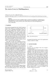
The physical problem is to find the sound field generated by a propeller scattered off by<br />
the fuselage of an aircraft. The pressure loading <strong>on</strong> the fuselage is an input to the interior<br />
noise problem. <str<strong>on</strong>g>Computati<strong>on</strong>al</str<strong>on</strong>g>ly, this is a good problem for testing curved wall boundary<br />
c<strong>on</strong>diti<strong>on</strong>s.<br />
Figure 1<br />
We will idealize the fuselage as a circular cylinder and the noise source (propeller) as<br />
a line source so that the computati<strong>on</strong>al problem is two-dimensi<strong>on</strong>al, figure 1. We will<br />
use a polar coordinate system centered at the center of the circular cylinder as shown.<br />
Dimensi<strong>on</strong>less variables with respect to the following scales are to be used.<br />
length scale<br />
velocity scale<br />
time scale<br />
density scale<br />
pressure scale<br />
The linearized Euler equati<strong>on</strong>s are<br />
= diameter of circular cylinder, D<br />
= speed of sound, c<br />
= DO_<br />
c<br />
= undisturbed density, p0<br />
-- PO C2<br />
(1)<br />
(2)<br />
cgp Ou Ov<br />
a-7+N+N =s (3)<br />
1
where<br />
Find the scattered sound field for _v = 8rr.<br />
(0.2)2 sinwt.<br />
GiveD(0) = lira rp2 for0 = 90 ° to 180 ° at A0 = 1 degree (--=<br />
State your grid specificati<strong>on</strong> and At used in the Computati<strong>on</strong>.<br />
Problem 2<br />
time average).<br />
This is the same as problem 1 above except that there is no time periodic source; i.e.,<br />
S = 0 in equati<strong>on</strong> (3). C<strong>on</strong>sider an initial value problem with initial c<strong>on</strong>diti<strong>on</strong>s t = 0,<br />
u = v = 0, and<br />
Find p(t) at the three points A (r = 5,0 = 90°), B (r = 5,0 = 135°), C (r = 5,0 = 180°).<br />
Give p(t) from t = 6 to t = 10 with At = 0.01. State the grid specificati<strong>on</strong> and the At<br />
used in the computati<strong>on</strong>.<br />
Problem 3<br />
Solve the axisymmetric linearized Euler equati<strong>on</strong>s to predict the scattering of acoustic<br />
waves from a sphere. The governing equati<strong>on</strong>s (including the acoustic source) are given by<br />
[i][i]I<br />
0 0 0<br />
+N =<br />
p<br />
--_ + Aexp(-B(gn2)((x - x,) 2 + r2))cos(wt)<br />
The length scale is given by the radius of the sphere, R. The ambient speed of sound,<br />
ao,, and the ambient density, po_, are used as the velocity and density scales, respectively.<br />
The pressure is n<strong>on</strong>dimensi<strong>on</strong>alized by 2<br />
p_ao_ and time is scaled by R/a_. For the source,<br />
use A = 0.01, B = 16, xs = 2 and w = 20rr.<br />
There are no c<strong>on</strong>straints <strong>on</strong> the maximum size of the domain or number of grid points;<br />
although, CPU time will be used in part to assess the algorithm.<br />
Submit the RMS pressure al<strong>on</strong>g the circle x 2 + y2 = 25 at A0 = 1 °, 0 measured from<br />
the x-axis. The computer used, CPU time per timestep, the number of timesteps per<br />
period of the source, the number of grid points and CPU memory per grid point should<br />
also be reported.<br />
2<br />
V<br />
r<br />
0<br />
0<br />
_'2<br />
=<br />
|<br />
J<br />
|<br />
=<br />
m<br />
m
Problem 4<br />
This is the same as Problem 3 except that the computati<strong>on</strong> is to be carried out in<br />
Cartesian coordinates.<br />
Solve the 3-D Cartesian linearized Euler equati<strong>on</strong>s to predict the scattering of acoustic<br />
waves from a sphere. The governing equati<strong>on</strong>s (including the acoustic source) are given by<br />
Ot [i] ;] 0 ]<br />
pJ<br />
_0<br />
+2_ +_0<br />
Ox Oy<br />
-Aexp(-B(en2)((x - xs) 2 + y2 + z2))cos(wt)<br />
The length scale is given by the radius of the sphere, R. The ambient speed of sound,<br />
ac_, and the ambient density, poo, are used as the velocity and density scales, respectively.<br />
The pressure is n<strong>on</strong>dimensi<strong>on</strong>alized by p_aoo2 and time is scaled by R/ao_. For the source,<br />
use A = 0.01, B = 16, xs = 2, and w = 207r.<br />
There are no c<strong>on</strong>straints <strong>on</strong> the maximum size of the domain or number of grid points;<br />
although, CPU time will be used in part to assess the algorithm.<br />
Submit the RMS pressure al<strong>on</strong>g the circle x 2 + y2 = 25 at A0 = 1°, 0 measured from<br />
the x-axis. The computer used, CPU time per timestep, the number of timesteps per<br />
period of the source, the number of grid points and CPU memory per grid point should<br />
also be reported.<br />
Problem 1<br />
Category 2 -- Duct Acoustics<br />
A finite length, both end open cylindrical shell (duct) of zero thickness is placed in a<br />
Uniform flow at a Mach number of 0.5 as shown in figure 2. A time periodic, distributed<br />
but very narrow spherical source is located at the geometrical center of the duct.<br />
0<br />
0<br />
0
Duct wall<br />
M=0.5___ \<br />
--_" D/2<br />
S<br />
1<br />
r<br />
Source x<br />
Figure 2<br />
The length L and the diameter D of the shell are equal (L = D). The flow variables and<br />
the geometrical quantities are n<strong>on</strong>dimensi<strong>on</strong>alized using D as the length scale, the ambient<br />
speed of sound a_ as the velocity scale, the ambient density p_ as the density scale, and<br />
2<br />
p_a_ as the pressure scale. Time is made dimensi<strong>on</strong>less by the time scale D/a_. The<br />
problem is axisymmetric and should be solved using the linearized Euler equati<strong>on</strong>s given,<br />
in dimensi<strong>on</strong>less form, as<br />
0 0<br />
0-7<br />
where the source S' is given by<br />
P<br />
" Moop + u<br />
M_u + p<br />
Mc_ v<br />
M_p + u<br />
S=0.1exp -48(gn2) _ (x 2+r 2) cos(kDt), withkD=167r.<br />
An equivalent set of equati<strong>on</strong>s could also be used. Calculate the intensity of sound, _-,<br />
al<strong>on</strong>g the circular arc x 2 + r 2 = (5/2) _ at A0 = 1 °, 0 measured from the x-axis. There is<br />
no requirement to use a specific domain or number of grid points. However, for algorithm<br />
assessment purposes the investigator is asked to report the computer used, the total CPU<br />
time, time step size, total number of time steps, total number of grid points, and the size<br />
of the physical domain.<br />
Problem 2<br />
C<strong>on</strong>sider the radiati<strong>on</strong> of sound from a thin wall duct as shown in figure 3. The param-<br />
eters of this problem have been so chosen that unless some fundamental understanding of<br />
duct acoustics such as duct modes, cutoff frequencies are incorporated in the design of the<br />
computati<strong>on</strong>al algorithm, the computed results would, invariably, be quite poor.<br />
?)<br />
0<br />
P<br />
?)<br />
+<br />
i<br />
i<br />
m<br />
i<br />
|<br />
m<br />
=<br />
i<br />
i<br />
t<br />
m<br />
E
, / circilar duct<br />
I incoming sound<br />
Figure 3<br />
o x<br />
_sound radiati<strong>on</strong><br />
For c<strong>on</strong>venience, we will use a cylindrical coordinate system (r, ¢, x) inside the duct<br />
and a spherical polar coordinate system (R, O, ¢) outside the duct. Dimensi<strong>on</strong>less variables<br />
with respect to the following scales are to be used.<br />
length scale = radius of duct, a<br />
velocity scale = speed of sound, c<br />
time scale = _-<br />
C<br />
density scale = undisturbed density, p0<br />
pressure scale = p0c 2<br />
C<strong>on</strong>sider a semi-infinite l<strong>on</strong>g circular duct with infinitesimally thin rigid wall as shown.<br />
Small amplitude sound waves enter the duct from the left and radiate out through the open<br />
end to the right. The incoming wave is a spinning duct mode with velocity and pressure<br />
given by<br />
i -'- Re<br />
P<br />
2 2 t/2<br />
(+ -t%m) Jn(pnmr)<br />
oJ<br />
-i 2: s'(...,,-)<br />
"--J.(u..:')<br />
hg r<br />
L J.(U..:)<br />
ei[(w2-#_,_) _x+n¢-wt]<br />
where (u, v, w) axe velocity comp<strong>on</strong>ents in the (x, r, ¢) directi<strong>on</strong>s. ,In( ) is the n th order<br />
Besselfuncti<strong>on</strong>. #nm is the mth zero of J_; i.e., ,,(#nrn)=0, n=0,1,2,., m 1,2,3, ....<br />
1. Find the directivity, D(0), of the radiated sound.<br />
D(8) = lim R2p2(R,O,¢,t),<br />
R'---* oo<br />
Give D(O) from 0 = 0 to 0 = 180 ° at A0 = 1 degree.<br />
5<br />
--= time average.<br />
R
2. Find the pressure envelope inside the duct al<strong>on</strong>g the four radial lines r = 0, 0.34, 0.55,<br />
0.79. The pressure envelope, P(x), is given by<br />
P(x)= max p(r,¢,x,t).<br />
over time<br />
Give P(x) from x = -6 to x = 0 at Ax = 0.1.<br />
For both parts of the problem, c<strong>on</strong>sider <strong>on</strong>ly n = 0, m = 2 and the two cases<br />
(a) co = 7.2<br />
(b) = 10.3<br />
Note: #o2 = 7.0156. You are to solve the linearized Euler equati<strong>on</strong>s.<br />
Category 3 m Turbomachinery Noise<br />
The purpose of these problems is to study the computati<strong>on</strong>al requirements for modeling<br />
the aeroacoustic resp<strong>on</strong>se of typical rotor-stator interacti<strong>on</strong>s that generates t<strong>on</strong>al noise in<br />
turbomachinery. You may solve either the full Euler or Ilne_(zedEuier equati<strong>on</strong>s. Be sure<br />
to specify the grid size, the total CPU time required, the CPU t:[me per period, and the<br />
type of computer used for each problem.<br />
and<br />
. :=<br />
This problem ........ is designed to test the ability of a numerical scheme to model the acoustic<br />
resp<strong>on</strong>se ofacascade to an incident "frozen gust_,',_<br />
C<strong>on</strong>slaeT_h_-c_scaae of flat-plate airfoils Shown in figure41 The mean flow is uniform<br />
and axial wi{h inflow velocity Uoo and s{atiC density po_. The inflow Mach number M_:{S<br />
0.5. The length (chord) of each plate is c, and {he gap-ico-chord ratio g/c is i.0.<br />
: We will use n<strong>on</strong>-dimensi<strong>on</strong>al variables with U_ as velodty scale, c as length scale,<br />
c/U_ as time scale, poo as density scale and pooU_ as pressure scale.<br />
The incident:vortical gust, which is carried al<strong>on</strong>g by the mean flow; has z and y<br />
velocities givefi by ......<br />
. L<br />
: : : : :: : Z72 L ::<br />
v = cos( x + av (2)<br />
respectiveiy;::where vG = 0.01. C<strong>on</strong>sider two cases. For CaSe 1, the Wavenumber/3 is<br />
g_r[2 Corresp<strong>on</strong>d{ng:{o an "interblade phase angle!' a of 5rr/2. The frequency w (same<br />
as the reduced frequency based <strong>on</strong> chord, k)_is equal to 5rr/2 (_ 7'864). For Case 2,<br />
a = k = 13_r/2 (_ 20.42). The gust is c<strong>on</strong>vected by the mean flow. Therefore, the<br />
x-wavenumber _ for both cases is equal to co.:<br />
7;<br />
Z !<br />
!<br />
m<br />
m<br />
N<br />
i<br />
I<br />
i<br />
l<br />
I<br />
m<br />
U<br />
IN
<str<strong>on</strong>g>Computati<strong>on</strong>al</str<strong>on</strong>g> __<br />
Domain _X .<br />
Ua_<br />
GUST<br />
Periodic Boundaty..__ _ Vgrid ---- U<br />
I<br />
0 1 2 x<br />
Reference Plate<br />
with length e<br />
Figure 4<br />
Using the frozen gust assumpti<strong>on</strong>, determine the magnitude of the pressure jump across<br />
the reference airfoil (the airfoil at y = 0) where Ap = Plower- Pupper. You need not<br />
solve for the gust c<strong>on</strong>vecti<strong>on</strong> as part of your numerical soluti<strong>on</strong>, but instead may simply<br />
impose an upwash <strong>on</strong> the airfoil surfaces given by (2). Also, determine the intensity of<br />
the radiated sound _2 al<strong>on</strong>g the lines z = -2 and z = +3. Finally, plot c<strong>on</strong>tours of the<br />
perturbati<strong>on</strong> pressure at time t = 2rrr_/w where n is an integer. If you are using a time<br />
marching algorithm, n should be large enough that the soluti<strong>on</strong> is temporally periodic.<br />
Your c<strong>on</strong>tour plots should show the instantaneous n<strong>on</strong>dimensi<strong>on</strong>al static pressure p for the<br />
entire computati<strong>on</strong>al domain.<br />
Problem 2<br />
This problem is designed to test the ability of a numerical scheme to simultaneously<br />
model the c<strong>on</strong>vecti<strong>on</strong> of vortical and acoustic waves in a cascade.<br />
Repeat Problem 1, but this time specify the gust al<strong>on</strong>g the upstream boundary of<br />
the computati<strong>on</strong>al domain. Then use your numerical algorithm to model the c<strong>on</strong>vected<br />
vortical wave and subsequent interacti<strong>on</strong> with the cascade. Apart from truncati<strong>on</strong> error,<br />
your soluti<strong>on</strong> should be identical to Problem 1. In other words, be careful to specify the<br />
phasing of the incoming gust such that the upwash <strong>on</strong> the airfoil has the same phase used<br />
in Problem 1.<br />
7
Problem 3<br />
This problem is designed to test the ability of a numerical scheme to model the p_0p-<br />
agati<strong>on</strong> of acoustic and vortical waves across a sliding-interface typical of those used in<br />
rotor stator interacti<strong>on</strong> problems.<br />
Repeat Problem 2, but translate the porti<strong>on</strong> of the grid aft of the line x = 2 in the<br />
positive ?]-directi<strong>on</strong> with speed 1. If possible, arrange the sliding grid moti<strong>on</strong> so that at<br />
times corresp<strong>on</strong>ding to the start of each period (t = 27rn/w) the sliding grid is in the<br />
original n<strong>on</strong>siiding positi<strong>on</strong>. This will aid in the plotting and evaluati<strong>on</strong> of soluti<strong>on</strong>s.<br />
Category 4 m Airframe and Automobile Noise<br />
Aeolian t<strong>on</strong>es, sound generati<strong>on</strong> by flow over a cylinder, are relevant to automobile<br />
antenna and airfl'ame noise. The purpose of this problem is to dem<strong>on</strong>strate computati<strong>on</strong><br />
of sound generati<strong>on</strong> by viscous flows.<br />
C<strong>on</strong>sider uniform flow at Math number 0.2 over a two-dimensi<strong>on</strong>al cylinder of diameter<br />
D = 1.9cln as shown in figure 5. The Reynolds number based <strong>on</strong> the diameter of the<br />
cylinder is 90,000. Perform numerical simulati<strong>on</strong>s to estimate the power spectra of the<br />
radiated sound in dB (per 20Hz bandwidth) at r/D = 35 and 0 = 60 °, 90 °, 120 ° over the<br />
Strouhal number, St = u/_-0 D, range of 0.01 < St __ 0'61 a{ ASt = 0.002,<br />
You may use a smaller Reynolds number in your simulati<strong>on</strong>. However, data may not<br />
be available for direct validati<strong>on</strong>.<br />
verged.<br />
Perform grid and time resoluti<strong>on</strong> studies to dem<strong>on</strong>strate that your soluti<strong>on</strong> has c<strong>on</strong>-<br />
Co<br />
v<br />
Figure 5<br />
8<br />
x<br />
L77:<br />
|<br />
R<br />
i<br />
i<br />
F<br />
le<br />
E
where<br />
ANALYTICAL SOLUTIONS OF THE CATEGORY 1,<br />
The linearized Euler equati<strong>on</strong>s are<br />
BENCHMARK PROBLEMS i AND 2<br />
K<strong>on</strong>stantin A. Kurbatskii<br />
Department of Mathematics<br />
Florida State University<br />
Tallahassee, FL 32306-3027<br />
1. ANALYTICAL SOLUTION OF THE PROBLEM 1<br />
Ou Op = 0<br />
0-7+ 0-7<br />
Op Ou Ov<br />
-_ + _x + o_ = s(x,_,_)<br />
S(x, y, t) = e-l"2((_-_')2 +u_)/W_sin(a_t)<br />
5t - 4,/_<br />
is the time-periodic acoustic source located at x = xs, y = 0. Here xs = 4, w = 0.2, w = 87r.<br />
Boundary c<strong>on</strong>diti<strong>on</strong>s are<br />
1) zero-normal-velocity at the surface of the cylinder<br />
v . n = O at x 2 4- y2 - (0.5)_<br />
2) radiati<strong>on</strong> boundary c<strong>on</strong>diti<strong>on</strong> for x, y --+ oc, i.e. the soluti<strong>on</strong> represents outgoing waves.<br />
By eliminating u" and v from (1) to (3), the equati<strong>on</strong> for p is,<br />
The boundary c<strong>on</strong>diti<strong>on</strong> (5) becomes<br />
O2p (O2p O2p_ e-b[(x-z,)2+y2]im(iaJe-i_t )<br />
o_ \-g_+ N_ ) =<br />
where b = In2/w 2<br />
(1)<br />
(2)<br />
(3)<br />
(4)<br />
(5)<br />
(6)<br />
(7)<br />
(s)
The soluti<strong>on</strong> for pressure, p, can be written as<br />
Substituti<strong>on</strong> of (10) into (7), (9) gives the problem for _(x,y)<br />
__OP=0 at z_+y2=0.25 (9) _;<br />
p(x,y,t) = !m(_(x,g)e -i_') (10)<br />
02D 02P -ia;e -b[(x-=')_+y_] (11)<br />
Ox---- 7 + _ + _2i_ =<br />
015 _ g2<br />
On -0 at x _+ =0.25 (12)<br />
radiati<strong>on</strong> boundary c<strong>on</strong>diti<strong>on</strong>s as x, y --4 oc (13)<br />
(11) is a n<strong>on</strong>-homogeneous I-Ielmholtz equati<strong>on</strong>. The problem (11) - (13) can be solved by the<br />
method of superpositi<strong>on</strong>. Let<br />
_(_,y) = pi(x,_) + p_(x,y) (14)<br />
where pi is the incident wave generated by the source and p_ is the wave reflected off the cylin-<br />
der. pi satisfies<br />
-4- w2pi --" -iwe -b[(_-_')_ +y_]<br />
and the outgoing wave c<strong>on</strong>diti<strong>on</strong>. When pi is found the problem for p_ becomes<br />
02pr 02pr<br />
Ox--- 7- + _ + W2p_ = 0 (16)<br />
Op____Z__ = Opi<br />
On On<br />
(15)<br />
at x 2 + g2 = 0.25 (17)<br />
To solve for p,(z, y) we use polar coordinates (r=, 0_) with the origin at x = z=, y = 0; thus the<br />
soluti<strong>on</strong> is independent of 0_. (16) reduces to the n<strong>on</strong>-homogeneous Bessel equati<strong>on</strong><br />
with boundary c<strong>on</strong>diti<strong>on</strong>s<br />
d2Pi d- 1 dpi -4-wZpi --iwe -br_ (18)<br />
dr] r s dr=<br />
pi(r=) is bounded at r= = 0 (19)<br />
10<br />
|
The Greens functi<strong>on</strong> for (18)- (19) is<br />
pi(rs)e -i_t represents outgoing waves as rs --, cc<br />
G(rs,() = ___(j0(w()H_l)(wr_), ( _< % < oc<br />
where J0 and H_ 1) are the zeroth order BesseI and Hankel functi<strong>on</strong>s respectively.<br />
The soluti<strong>on</strong> for pi(rs) is<br />
pi(r_) = G(r_,_)[-iwe-b_2]d_<br />
_0 °(3<br />
With pi found, the problem for the reflected wave, pr, is<br />
where B(O) is now known.<br />
02pr 1 Opt 1 02p_<br />
Or------ _ + -_ r Or + r 2 002 + _o2p_ = 0<br />
Pr<br />
Or -B(O) at r=0.5<br />
By separating variables in (23) pr(r, 0) is represented by Fourier series<br />
pr(r,O) = E CkH_l)(ra_)c°s(kO) (25)<br />
k=0<br />
(1)<br />
where H k is the Hankel functi<strong>on</strong> of the first kind. Only cosine terms are retained in (25) be-<br />
cause the problem is symmetric about the x-axis.<br />
The coefficients Ck of (25) are found by applying the boundary c<strong>on</strong>diti<strong>on</strong> (24). This gives<br />
Heree0 =I, ek=2, k= 1,2, ....<br />
Ck "- 71.co[2kH(1) (1) (W 2<br />
L-L- k (W/2)-- Hk+l, / )]<br />
gT<br />
(20)<br />
(21)<br />
ek B(O)co (kO)dO (26)<br />
Finally, by means of the asymptotic formulas for H_ 1) (see ref.(1)), it is easy to find that the<br />
directivity<br />
D(O) = llm rp 2 is given by<br />
r --), oo<br />
D(O) = (Jo(w_)e -b_ d( + Cke-i(_'_/2+'_/4) r<br />
cos(kO)<br />
k=O<br />
II<br />
(22)<br />
(23)<br />
(24)<br />
(27)
I. ANALYTICAL SOLUTION OF THE PROBLEM 2<br />
This is an initial-value problem governedby the linearized Euler equati<strong>on</strong>s<br />
The initial c<strong>on</strong>diti<strong>on</strong>s are:<br />
and<br />
Here xs = 4, w = 0.2.<br />
and<br />
by<br />
The boundary c<strong>on</strong>diti<strong>on</strong>s are:<br />
Ou Op<br />
-_ + N = 0 (28)<br />
Ov Op<br />
N + _yy = 0 (29)<br />
Op Ou Ov<br />
N + _ + N = 0 (30)<br />
u=v=0 at t 0 (31)<br />
p(x, y, 0) = e -u'2((,-*'):+y2)/w2<br />
l<br />
at t = 0 (32) _*<br />
v.n=O at x 2+y2=(0.5) 2, (33)<br />
when x, y ---+ oc the soluti<strong>on</strong> respresents outgoing waves. (34)<br />
Soluti<strong>on</strong> of the problem (28) - (34) can be found in terms of velocity potential ¢(x, y, t) defined<br />
0¢ 0¢ 0¢<br />
= N' "= 0_' p - ot (35)<br />
It is easy to show from (28) - (30) and (35) that the governing equati<strong>on</strong> for ¢ is the wave equa-<br />
ti<strong>on</strong> which may be written in polar coordinates (r, O) as<br />
Initial c<strong>on</strong>diti<strong>on</strong>s (31) and (32) are reduced to<br />
t=O:<br />
1<br />
02¢ f82¢ 10¢ __02¢_<br />
Ot 2 \ Or 2 + r -_r + r 2 002 ,] = 0 (36)<br />
¢=0, Ot - e (37)<br />
12<br />
=<br />
i<br />
Ii<br />
E<br />
l<br />
E<br />
E
where b = In2/w 2.<br />
Boundary c<strong>on</strong>diti<strong>on</strong> (33) becomes<br />
0¢ o at r 0.5 (3S)<br />
Or<br />
The problem (36) - (38) can be solved by the method of superpositi<strong>on</strong>. Let<br />
¢(r,/9,t) = ¢_(r,/9,t)+ Cr(_,/9,t) (39)<br />
where ¢i is the incident wave generated by the initial pressure pulse, and Cr is the wave reflected<br />
off the cylinder. ¢i(r,/9, t) satisfies<br />
with the initial c<strong>on</strong>diti<strong>on</strong>s<br />
02¢i (0 2¢i 1 0¢i<br />
Or2 _,0_ + --_, ] = 0 (4O)<br />
0¢i _ _b_ (41)<br />
t=O: ¢i=0, Ot e<br />
where (%,/gs) are the polar coordinates with the origin at x = xs, y = O.<br />
The initial value problem of (40) and (41) can be solved by means of the order-zero Hankel<br />
transform. The soluti<strong>on</strong> is (see ref.(2))<br />
or in terms of (r,/9) coordinates<br />
The problem for ¢_ is<br />
¢i(_s,t) = -2-_ lf0_<br />
e--b_2/(4b) Zo(o.)rs ).si12(o3t )do.)<br />
¢i(r,O,t) = Ai(r,O,w)sin(wt)dw (42)<br />
fo :x)<br />
where Ai(r, 0,w) = 1 _b_2/(4b) r £bo _0(wv/_2+ x_ - 2_x_co_0) (43)<br />
02¢_ Ot 2 (02¢r _,0r 2 +-_+ 1r 0¢r Or r12 02¢_) 002 =0 (44)<br />
0¢_ 0¢i<br />
0---_-= - 0--_- at r = 0.5 (45)<br />
In view of (42) we will represent the soluti<strong>on</strong> for ¢_ by Fourier sine transform it t,<br />
¢_(r,/9, t) = A_(r,O,w)sin(wt)dw (46)<br />
f0 _<br />
13
Substituti<strong>on</strong> of (46)into (44), (45) gives<br />
(47) can be solved by separati<strong>on</strong> of variables giving,<br />
02At 1 OAr 10ZA,.<br />
Or 2 + + +ofiA = 0 (47) :<br />
r Or r 2 002 ._<br />
_rr = B(6,o_) at r =0.5 (48)<br />
|<br />
where B(0,0J)= OA.___i ]<br />
(49) i<br />
Or It=0.5<br />
O0<br />
A4r, e,_) = _ Ck(_)lC_l)(r_)co_(ke) (50)<br />
k=0<br />
The coefficients Ck of (50) are found by applying the boundary c<strong>on</strong>diti<strong>on</strong> (48). It is straight-<br />
forward to find,<br />
_ B(e,_)cos(ke)de (51)<br />
Ck = 7rw[ZkH(1) ' ,,,,<br />
--d k (w/z)- g_l(w/2)]<br />
Finaiiy, substituti<strong>on</strong> of (50), (51) into (46) and <strong>on</strong> combining (42), (46), the velocity potential<br />
is found,<br />
where<br />
¢(r,e,t) = A(r,e,_)_i.(_t)d_ (52)<br />
j00 _<br />
A(_,e,_) = Jo(_/_ _+ _ - 2_z._o.e) + F_.n_<br />
g-bw=/(4b){2/) OO [ 71"_3[_-H_I) (O2/2)_kH(kl)(Fc'O)g°'S(ICe)-k=0<br />
.. D "(1) k+l (w/2)]<br />
r + (53)<br />
]0 v/0.25 + x] - x,cos_ J<br />
The pressure field may be calculated by<br />
p(_,e,t) = _o¢ = _ A(_,e,_)_¢o.(_t)d_<br />
Ot<br />
f0 _<br />
REFERENCES<br />
1. Abramowitz, M.; and Stegun, I.A.: Handbook of Mathematical Functi<strong>on</strong>s.<br />
2. Tam, C.K.W.; and Webb, J.C.: Dispersi<strong>on</strong>-Relati<strong>on</strong>-Preserving Finite Difference Schemes for<br />
<str<strong>on</strong>g>Computati<strong>on</strong>al</str<strong>on</strong>g> Acoustics. J. Comput. Phys., vol. 107, Aug. 1993, pp. 262-281.<br />
14<br />
(54)<br />
=<br />
I<br />
!<br />
i[]<br />
m
SCATTERING OF SOUND BY A SPHERE: CATEGORY 1: PROBLEMS 3_ND<br />
Philip J. Morris*<br />
Department of Aerospace Engineering<br />
The Pennsylvania State University<br />
University Park, PA 16802<br />
INTRODUCTION<br />
The scattering of sound by a sphere may be treated as an axisymmetric or three-dimensi<strong>on</strong>al<br />
problem, depending <strong>on</strong> the properties of the source. In the two problems here, the soluti<strong>on</strong> is<br />
axisymmetric. The method described below uses a Hankel transform in spherical polar coordinates.<br />
Additi<strong>on</strong>al details of the soluti<strong>on</strong>, including the numerical evaluati<strong>on</strong> of spherical Hankel functi<strong>on</strong>s,<br />
are given by Morris [3]. This reference also includes soluti<strong>on</strong>s for n<strong>on</strong>-rigid spheres. The same method<br />
may be applied to cylinder scattering problems as described by Morris [2].<br />
EXACT SOLUTION<br />
C<strong>on</strong>sider the scattering of sound from a spherically-symmetric source by a sphere of radius a. The<br />
source is centered at S, a distance x_ from the center of the sphere. A spherical coordinate system<br />
(r, 9, ¢) has its origin at the center of the sphere. The line joining the centers of the sphere and the<br />
source defines 9 = 0. Thus, the problem is independent of ¢. The density and speed of sound are Po,<br />
co respectively. The radial distance from the center of the source is denoted by R.<br />
A periodic soluti<strong>on</strong> is sought in the form e -_t. The source has a spatial distributi<strong>on</strong> given by<br />
p,(R). The pressure, po(r, 0), satisfies the equati<strong>on</strong>,<br />
where, ko = w/co.<br />
r20r r2or) +r2sinO00 sinO +koPo--p_(R ) (1)<br />
Let the pressure be decomposed into incident and scattered fields: pi_c(R) and p,c(r, 9),<br />
respectively. Then p_nc(R) satisfies the equati<strong>on</strong>,<br />
*Boeing/A. D. Welliver Professor of Aerospace Engineering<br />
1 d R2 + kop_nc -- p_ (R)<br />
R 2 dR<br />
15<br />
o<br />
(2)
and the scatteredfield satisfiesthe homogeneousform of Eq. (I). -::_ ,<br />
The soluti<strong>on</strong> for the incident field is obtained here through the useof a Hankel transform, given by<br />
oc<br />
G(s)= -2 R2 jo(sR)g(R)dR (3) _'<br />
T" 0<br />
g(R)--/s2j°(sR)G(s)dSo (4) i<br />
where jn(z) is the spherical Bessel functi<strong>on</strong> of the first kind and order n. The properties of spherical<br />
Bessel functi<strong>on</strong>s are given by Abramowitz and Stegun [1]. i<br />
Now, integrati<strong>on</strong> by parts and the use of general expressi<strong>on</strong>s for the derivatives of spherical Bessel | |<br />
functi<strong>on</strong>s [1], gives i<br />
_ n _3o(ns) N_ n _ dR = -s2a(s) (5) .<br />
So, the Hankel transform of Eq. (2) leads to i<br />
where,<br />
p_n_(R) = - jo(sR)P_(s) z<br />
0 (s 2 _ k2o) ds (6) _--<br />
P_(s) = -rr2/R2jo(sR)p,(R)d R<br />
0<br />
Now, with R = Cr 2 + x_ - 2rx_ cos 0, Abramowitz and Stegun [1] give an additi<strong>on</strong> theorem for<br />
spherical Bessel functi<strong>on</strong>s,<br />
jo(_n) - _n<br />
sin(sR)<br />
-- -- _(2n + 1) j,,(sr) jn(sx,) P,(cos0)<br />
where P, (cos 0) is the Legendre polynomial of order n. Thus, from Eqs. (6) and (8),<br />
where,<br />
oo<br />
n=0<br />
c_<br />
p_,_(R) = - y_' (2n + 1) Pn(cos 0) I_(r)<br />
n=0<br />
f s_j.(_) j.(_) P_(_)<br />
(s 2 _ k2 ) es<br />
The general soluti<strong>on</strong> for the scattered field may be written in separable form as<br />
oo<br />
p_(r,O) = _ A_h_)(kor) P,(eos 0)<br />
n_O<br />
16<br />
(7)<br />
(8)<br />
(9)<br />
(_o)<br />
(11)<br />
z
where h O) (z) is the spherical Hankel functi<strong>on</strong> of the first kind and order n.<br />
that,<br />
where,<br />
At the boundary of the sphere we require that the normal derivative of the pressure be zero. So<br />
A,, = (2n, + 1) I'_(a)<br />
ko (1), (12)<br />
hn (koa)<br />
j (82_ ko ds<br />
0<br />
j_(z) denotes the derivative of j_(z) with respect to z and is given by<br />
j'n(z) = jn-l(Z) - (n + 1) jn(z)/z<br />
with fo(Z) = -jl (z). Identical forms of expressi<strong>on</strong> may be used for the spherical Hankel functi<strong>on</strong><br />
derivatives.<br />
Now, c<strong>on</strong>sider a spherically-symmetric, spatially-distributed Gaussian source given by<br />
Then, from Eq. (7),<br />
ps(R) = aexp(-bR 2)<br />
Ps(s) = a exp(_s2/4b ) (16)<br />
2bv/_<br />
In this case, neither the incident field nor the unknown integrals I_ (a) and I'_ (a) may be evaluated<br />
analytically. However, they may be obtained numerically. The numerical procedure used involves the<br />
use of an integrati<strong>on</strong> c<strong>on</strong>tour in the complex s plane to include the effect of the pole at s = ko. It is<br />
described by Morris [2] and is not repeated here.<br />
and<br />
In the present problem, where the source is introduced into the linearized energy equati<strong>on</strong>,<br />
(13)<br />
(14)<br />
(15)<br />
a = -ikoA (17)<br />
b = B<br />
A=0.01, B=16, xs=2<br />
Different frequencies are c<strong>on</strong>sidered in the model problems.<br />
REFERENCES<br />
[1] M. Abramowitz and I. A. Stegun. Handbook of Mathematical Functi<strong>on</strong>s. Dover, 1965.<br />
[2] P. J. Morris. The scattering of sound from a spatially-distributed axisymmetric cylindrical source<br />
by a circular cylinder. Journal of the Acoustical Society of America, 97(5):2651-2656, 1995.<br />
[3] P. J. Morris. Scattering of sound from a spatially-distributed, spherically-symmetric source by a<br />
sphere. Journal of the Acoustical Society of America, 98(6):3536-3539, 1995.<br />
17<br />
(18)
!<br />
?<br />
!<br />
|<br />
IE<br />
r,<br />
Im<br />
i
RADIATION OF SOUND FROM A POINT SOURCE<br />
IN A SHORT DUCT<br />
M. K. Myers<br />
The George Washingt<strong>on</strong> University<br />
Joint Institute for Advancement of Flight Sciences<br />
Hampt<strong>on</strong>, VA<br />
INTRODUCTION<br />
It is the purpose of this paper to provide, in relatively brief form, a summary of a boundary<br />
integral approach that has been developed for calculating the sound field radiated from short ducts in<br />
uniform axial moti<strong>on</strong>. The method was devised primarily to study sound generated by rotating sources<br />
in the duct, as is of current practical interest in c<strong>on</strong>necti<strong>on</strong> with ducted-fan aircraft engines. Detailed<br />
-:1/<br />
7<br />
?z<br />
background <strong>on</strong> the fan source applicati<strong>on</strong> of the technique can be found in refs. 1 and 2. The author has<br />
not previously discussed the simpler m<strong>on</strong>opole source case of interest in these proceedings. However,<br />
readers desiring a more detailed treatment than will be included here should have little difficulty in<br />
extracting it from those references after making the relatively minor modificati<strong>on</strong>s necessary to adapt the<br />
analyses to the m<strong>on</strong>opole case.<br />
It should be noted that other authors have also c<strong>on</strong>sidered radiati<strong>on</strong> from short ducts. In<br />
particular, readers may find the finite-element approach of Eversman [3] of interest as well as the<br />
alternate boundary integral method treatments of Martinez [4] and of Dunn, Tweed, and Farassat [5].<br />
BOUNDARY INTEGRAL EQUATION<br />
The problem to be c<strong>on</strong>sidered is illustrated in fig. 1. An infinitesimally thin, rigid circular<br />
cylinder of radius a and length L moves at subs<strong>on</strong>ic speed V in the negative x 3 directi<strong>on</strong> relative to a<br />
frame of reference 2 fixed in fluid at rest. The duct encloses a m<strong>on</strong>opole source located at its center,<br />
which is taken as the origin of a co-moving system X. The m<strong>on</strong>opole emits sound harm<strong>on</strong>ically at<br />
circular frequency m in the moving frame X. The objective is to determine the acoustic field radiated<br />
into infinite space through the ends of the moving duct.<br />
The field is assumed to be described by the linearized equati<strong>on</strong>s of ideal isentropic compressible<br />
fluid moti<strong>on</strong>. The problem is expressed in a scattering formulati<strong>on</strong> in which the acoustic pressure is<br />
written as p = p_ + Ps, where the incident pressure p_ is the free-space field radiated by the m<strong>on</strong>opole<br />
source in the absence of the duct. The scattered pressure ps(z_,t) is then sought as an outgoing soluti<strong>on</strong><br />
to the homogeneous wave equati<strong>on</strong> subject to appropriate boundary c<strong>on</strong>diti<strong>on</strong>s <strong>on</strong> the inner and outer<br />
surfaces of the duct.<br />
As shown elsewhere [1, 2], an integral representati<strong>on</strong> of p_ is obtained by utilizing generalized<br />
19
functi<strong>on</strong> theory to accountfor the fact that Psis disc<strong>on</strong>tinuousacrossthewall of the duct. The<br />
representati<strong>on</strong>is the formal soluti<strong>on</strong> of a generalizedwave equati<strong>on</strong>satisfiedby Ps, which hasa source<br />
term that arisesbecauseof the disc<strong>on</strong>tinuityin Psacrossthe wall. It expressesthe scatteredpressureat<br />
any point in termsof the pressurejump Aps acrossthe wall in the form<br />
4r_ps(:_,t)- cl &a f[0[r]l---_] [ A pscos0] ],,dS - f=o f [ r2il---_rlJr, A p cos0 ] dS (1)<br />
In eq. (1), r = ]gl is the radiati<strong>on</strong> distance between a source point <strong>on</strong> the moving surface f = 0 and the<br />
observer at _, 0 is the angle between f and the normal to f = 0 at the source point, and Mr is the<br />
comp<strong>on</strong>ent of the surface Mach number vector in the directi<strong>on</strong> of f. The speed of sound in the<br />
undisturbed medium is denoted by c, and the subscript "_" indicates that the integrands in<br />
eq. (1) are to be evaluated at the emissi<strong>on</strong> time z" which satisfies the retarded time equati<strong>on</strong> t-v-r/c=0.<br />
The boundary integral equati<strong>on</strong> from which the unknown jump Aps al<strong>on</strong>g the duct can be<br />
determined is obtained by applying c<strong>on</strong>diti<strong>on</strong> that the normal comp<strong>on</strong>ent of acoustic particle velocity<br />
vanishes <strong>on</strong> both sides of the duct surface f=0. This is equivalent to 0p]0n = 0 <strong>on</strong> f=0, or<br />
aps/an = - @i[C_l <strong>on</strong> f = 0 (2)<br />
where n is the directi<strong>on</strong> normal to the surface f = 0. Use of eq. (1) in eq. (2) leads to the integral<br />
equati<strong>on</strong><br />
-4_xOPi l = lim<br />
a la<br />
On cOt<br />
f=0 f I .r211_M r- c°s°l [j, ' dS t<br />
in which _ denotes any observer point <strong>on</strong> the moving surface f = 0. Equati<strong>on</strong> (3) is the boundary<br />
integral equati<strong>on</strong> which is solved numerically in the current analysis to find the unknown jump Ap_<br />
across f = 0. Once Ap_ is known, then the scattered pressure at any point in space can be calculated<br />
using eq. (1) and added to the incident pressure to obtain the radiated field.<br />
ANALYSIS OF BOUNDARY INTEGRAL EQUATION<br />
The integrals in eq. (3) are highly singular when r = 0, i.e., when the source point <strong>on</strong> f = 0<br />
coincides with the observer point :_o- To solve the integral equati<strong>on</strong> numerically it is necessary that this<br />
singular behavior be analyzed in detail. This is most c<strong>on</strong>veniently d<strong>on</strong>e by first expressing eq. (3) in<br />
terms of the translating coordinate frame _ in which, as indicated in fig. 1, cylindrical observer and<br />
source coordinates _ =(Rcos_, Rsin_, X3) and Y: (aeos4}, asintD/,Y3) are introduced.<br />
2O<br />
(3)<br />
z<br />
i<br />
i<br />
w:<br />
i<br />
E-<br />
E
ef. 6.<br />
Theincident pressureemitted by the translatingm<strong>on</strong>opolecan be obtained,for example,from<br />
In complexform it can be written as<br />
Pi=15(X3,R) exp[-i(° (t+MX3]cl32)]<br />
in which M = V/c, 132= 1 - M 2, and the amplitude _ is given by<br />
4nlb(X3,R) = - pc A<br />
[,iw (-MXa+IX_+[ _2R2) + MX3<br />
cl32 X_+132R 2 (X32 + 132R2) 3/2<br />
exp(<br />
Here A is the volume strength of the m<strong>on</strong>opole and p is the density of the undisturbed medium.<br />
follows that the left side of eq. (3) is<br />
where P(X3) = O_IOR[R=a.<br />
-4rrP(X3) exp [-it,) (t +MX3/c132)]<br />
Because of the symmetry of the duct, bps will have the same complex form as the expressi<strong>on</strong> in<br />
(6) when expressed in the moving coordinate frame. Thus bps is written as<br />
Ap_ : _(X3) exp [-i60(t +MX3/cl32)]<br />
The remaining quantities in the integrands of eq. (3) are also easily expressible in the translating<br />
cylindrical coordinates, although the details are omitted here. They can be found in refs. 1 and 2. After<br />
substituti<strong>on</strong> of eqs. (6 and 7) into eq. (3) and repetiti<strong>on</strong> of precisely the same algebraic steps as in refs. 1<br />
and 2, the boundary integral equati<strong>on</strong> (3) assumes the complex form<br />
-4riP(X3) = 2ap 2<br />
in which u? (Y3, _) is defined by<br />
L/2 1_<br />
lira d f _(Y3) fvcY ,,) d_dY 3 (8)<br />
R-a OR -I_ o<br />
_ (Y3,_) = (Rcos_ -a)[-- ia _ 1 ]<br />
_2+B (_2+B) 3/2 exp (itz _2_--B) (9)<br />
In eq. (9), the abbreviati<strong>on</strong>s ¢ =Y3-X3 and B=[32(R2+ a2-2aRcos _) have been introduced, with<br />
21<br />
It<br />
(4)<br />
(5)<br />
(6)<br />
(7)
_:C-_ and _=,.o/ct32.<br />
Equati<strong>on</strong> (8) casts the boundary integral equati<strong>on</strong> in a form from which its singular behavior may<br />
be extracted explicitly. The analysis necessary to do so is fairly lengthy, however, and it will be <strong>on</strong>ly<br />
summarized here in symbolic form; more detail will be found in a forthcoming publicati<strong>on</strong> [7]. First, it<br />
is seen in eq. (9) that the singularity occurs when Y3=X3(_=0),_=0 and R-a-h=0. Expansi<strong>on</strong> of<br />
for small _,_,h results in<br />
1 i_- R*2<br />
(_Z+Bo)3/z j (_2 +B0)3/2<br />
in which Bo=[32(h2+a2_ 2) and the omitted terms are all O(1) or smaller. Let the terms shown in eq.<br />
(10) be denoted as _o(Y3,#) and define q=_-_0- This functi<strong>on</strong> is completely regular. Then the<br />
circumferential integral in eq. (8) is written as<br />
f@d* +fVod* =I._(V_)+I(Y_)<br />
0 o<br />
such that the first integral (Ins) is n<strong>on</strong>singular and the sec<strong>on</strong>d (I) can be evaluated analytically because it<br />
c<strong>on</strong>tains <strong>on</strong>ly quadratic expressi<strong>on</strong>s in _. After carrying out this integrati<strong>on</strong> it is found that<br />
I(Y3) = Q,_(Y3) ÷ Qs(Y3), where Q,_ is also completely n<strong>on</strong>singular at Y3 =X3, h=O. The term Qs<br />
c<strong>on</strong>tains the singularity and is discussed further below.<br />
If the results just described are substituted back into eq. (8), that equati<strong>on</strong> becomes<br />
-4r_P(X3) :2a[32 I? _(Y3)<br />
l-L/2 -ff_ jR= dY3 + lima._ aRj<br />
after the radial derivative of the n<strong>on</strong>singular integrals <strong>on</strong> R=a has been evaluated analytically, and in<br />
which<br />
-u2[ ¢_2 +[32Cn2+aR_2) J_2+[32h2<br />
The entire singular nature of eq. (18) is now isolated in the integral (13) and the final step in the analysis<br />
is to remove the singularity from this integral by appropriate expansi<strong>on</strong> about _ =0 of the n<strong>on</strong>singular<br />
bracketed factor in the integrand of (13). When this is carried out it is found that the last term <strong>on</strong> the<br />
right of eq. (12) is expressible as<br />
22<br />
+<br />
• , ,<br />
=:<br />
(lO)<br />
(11)<br />
(12)<br />
(13)<br />
=<br />
[<br />
l
1<br />
-g (Y3)<br />
lim .... - _ (X 3) - _ _ _(X3) ÷ -- --<br />
-_I ] dY3 "K '_ (X3) + 1<br />
R-a OR a13 X/_2/a2132+n2 _2 2a2132 a13<br />
with _,=±L/2-X 3. The integral remaining in eq. (14) is also n<strong>on</strong>singular at _=0.<br />
(X3) - _ Z(X3)l°g (14)<br />
The result of all this is that the integral equati<strong>on</strong> (12) now involves <strong>on</strong>e double integral over Y3<br />
and @ and two single integrals over Y3, all of which are completely n<strong>on</strong>singular. The original<br />
singularity in eq. (18) has been integrated analytically and gives rise to the explicit terms <strong>on</strong> the right<br />
side of eq. (14).<br />
NUMERICAL SOLUTION<br />
The soluti<strong>on</strong> of the integral equati<strong>on</strong> (12) is obtained numerically using the method of collocati<strong>on</strong><br />
after expressing the unknown _(X3) in terms of suitable shape functi<strong>on</strong>s. It is known that a unique<br />
soluti<strong>on</strong> exists <strong>on</strong>ly if certain edge c<strong>on</strong>diti<strong>on</strong>s are specified, and these are incorporated into _ by<br />
enforcing a Katta c<strong>on</strong>diti<strong>on</strong> at the trailing edge of the duct and an inverse square-root singularity at the<br />
leading edge. Accordingly, the jump is written as<br />
_(X,) =a0 _ +_/1-4X2/L 2 ,+a2--_2+_a j [ L 2<br />
j=3<br />
in which the square-root factor in the numerator guarantees the correct functi<strong>on</strong>al form for the vanishing<br />
of _ at the trailing edge to comply with the Kutta c<strong>on</strong>diti<strong>on</strong>.<br />
The expansi<strong>on</strong> (15) is then substituted into eq.(12) and the integral equati<strong>on</strong> is evaluated at J + 1<br />
suitably chosen points al<strong>on</strong>g the length of the duct. This results in the algebraic system<br />
-47zP(X3i) :E ajKj(X3i)<br />
j:o<br />
J<br />
i=l,2,...,J+l<br />
from which the J + 1 c<strong>on</strong>stants aj are obtained. The coefficients Kj(X3i ) are calculated from the<br />
expressi<strong>on</strong>s in the previous secti<strong>on</strong> utilizing a four-point Gauss-Legendre quadrature scheme in which the<br />
duct surface is discretized into panels based <strong>on</strong> the wavelengths of oscillati<strong>on</strong> in • and X 3 of the<br />
various integrands for each j. A minimum of <strong>on</strong>e panel per wavelength in the circumferential directi<strong>on</strong><br />
and four per wavelength in the axial directi<strong>on</strong> are used, and the scheme has been extensively tested for<br />
23<br />
(15)<br />
(16)
accuracy. The numberof shapefuncti<strong>on</strong>sJ is chosensufficiently large to captureat Ieast 2-3 t_mes the<br />
number of oscillati<strong>on</strong>s in _ expected al<strong>on</strong>g the duct; this number can be inferred from the incident field<br />
given in eq. (6).<br />
RESULTS<br />
Numerical predicti<strong>on</strong>s from the theory outlined in thispaper are illustrated in figs. 2 and 3.<br />
Figure 2 corresp<strong>on</strong>ds to the case of primary interest in the current proceedings: the forward Mach<br />
number is 0.5, the duct (D) diameter and length are both I m, and the dimensi<strong>on</strong>less clrcular frequency<br />
is tzD/c=16r_. On the figure is shown the sound pressure level in dB re lO-51.tPa radiated from a<br />
m<strong>on</strong>opole for which pc tAI= IN. The polar plot gives the SPL of the incident field al<strong>on</strong>e and that of the<br />
total field in the presence of the duct <strong>on</strong> a spherical radius 2.5m from the origin of _. The angles 0 °<br />
and 180 ° corresp<strong>on</strong>d to the exit and inlet ends of the duct, respectively. As would be expected at this<br />
relatively high frequency, the duct causes very little scattering in the axial directi<strong>on</strong>s. There is, however,<br />
a lateral shielding effect that cuts the SPL about 20dB around the 90 ° directi<strong>on</strong> as is seen in all<br />
problems of this type [1, 2, 7].<br />
Figure 3 illustrates the directivity found for the same case except with the frequency reduced to<br />
wD/c=4.409n (corresp<strong>on</strong>ding to 750 Hz). While the axial scattering is somewhat str<strong>on</strong>ger in this case,<br />
the duct obviously affords minimal lateral shielding at the lower frequency.<br />
ACKNOWLEDGMENTS<br />
This research was supported by NASA Langley Research Center under Cooperative Agreement<br />
NCCI-14. Essential assistance with computer code development was provided by Mr. Melvin<br />
Kosanchick III, Ms. Barbara Lakota and Mr. Jas<strong>on</strong> Buhler.<br />
.<br />
.<br />
.<br />
REFERENCES<br />
Myers, M. K. and Lan, J. H., "Sound Radiati<strong>on</strong> from Ducted Rotating Sources in Uniform Moti<strong>on</strong>."<br />
AIAA Paper No. 93-4429, October 1993.<br />
Myers, M. K., "Boundary Integral Formulati<strong>on</strong>s for Ducted Fan Radiati<strong>on</strong> Calculati<strong>on</strong>s."<br />
Proceedings of First Joint CEAS/AIAA Aerocoustics C<strong>on</strong>ference, Munich, Germany, Vol. I, June<br />
1995, pp. 565-573.<br />
Eversman, W., "Ducted Fan Acoustic Radiati<strong>on</strong> Including the Effects of N<strong>on</strong>uniform Mean Flow and<br />
Acoustic Treatment." AIAA Paper No. 93-4424, October 1993.<br />
24<br />
i
7.<br />
,<br />
,<br />
.<br />
Martinez, R., "Liner Dissipati<strong>on</strong> and Diffracti<strong>on</strong> for an Acoustically Driven Propeller Duct." AIAA<br />
Paper No. 93-4426, October 1993.<br />
Dunn, M., Tweed, J. and Farassat, F., "The Predicti<strong>on</strong> of Ducted Fan Engine Noise via a Boundary<br />
Integral Equati<strong>on</strong> Method." AIAA Paper No. 96-1770, May 1996.<br />
Morse, P. M. and Ingard, K. U., Theoretical Acoustics, McGraw-Hill, New York, 1968, pp. 723-724.<br />
Myers, M. K, and Kosanchick, M., "Computati<strong>on</strong> of Sound Radiated from a Fan in a Short Lined<br />
Duct." To appear as AIAA Paper No. 97-1711, May 1997.<br />
r_<br />
/<br />
R<br />
\<br />
x Vt<br />
,(<br />
L<br />
_J<br />
J<br />
•w X 3<br />
Figure 1. Duct geometry and coordinate systems.<br />
25
13.<br />
O<br />
o,I<br />
nn<br />
13.<br />
(/3<br />
_9<br />
Q.<br />
IE<br />
-.i<br />
O<br />
O3<br />
=I.<br />
o<br />
m<br />
"o<br />
J<br />
13.<br />
r.f)<br />
-J<br />
{/)<br />
O,.<br />
"O<br />
t-<br />
O<br />
O9<br />
180 ..... TotalField<br />
iI ..... IncidentField<br />
I I I I I I I I I I I I<br />
"-.., 160 [-90 o ."<br />
120° _<br />
140...........<br />
" o<br />
60<br />
•. .....,-."<br />
• ....""<br />
-.. ..-<br />
...-"-_" .....120 ..............<br />
• :_ .---"_-_6o: -_:_.-. :::<br />
Is0q , 3o°<br />
,'" .... ......... ,o.............<br />
,<br />
i .j,<br />
l i i i , ....a. ...._ _ i .., li<br />
Figure 2. Sound pressure level at spherical radius 2.5m;<br />
L=D=Im, M=0.5, coD/c--16n.<br />
I I<br />
1200.<br />
I i I<br />
180<br />
160<br />
.................. 140<br />
.......... 120<br />
.Y .-."::_. .. 100<br />
_0°<br />
I I I I<br />
..... IncidentField<br />
TotalField<br />
-',, .. ..<br />
._ .,.......,.._<br />
.60 °<br />
7"'" .""" .-_¸_' 80_<br />
150" _j,'/ .:-," " t' ':,-.: ",'-----,x.. 30 °<br />
- '. ,_'_,"'/-- .....60...... ' " ",<br />
. t ." ""...,' ._'." " "" "" "" "'" ' _ '<br />
Figure 3. Sound pressure level at spherical radius 2.5m;<br />
L=D=lm, M=0.5, o)D/c=4.409_.<br />
26<br />
I<br />
ilJ<br />
i<br />
J<br />
r<br />
F
EXACT-SOLUTIONS FOR SOUND RADIATION FROM A<br />
Y. C. Cho<br />
NASA Ames Research Center<br />
Mail Stop 269-3, Moffett Field, CA 94035-1000<br />
K. Uno Ingard<br />
Department of Physics<br />
Massachusetts Institute of Technology<br />
Cambridge, MA 02139<br />
SUMMARY<br />
CIRCULAR DUCT<br />
This paper presents a method of evaluati<strong>on</strong> of Wiener-Hopf technique soluti<strong>on</strong>s for sound radiati<strong>on</strong> from an<br />
unflanged circular duct with infinitely thin duct wall, including mean flows.<br />
1. INTRODUCTION<br />
Sound radiati<strong>on</strong> from circular ducts is a classical acoustics problem. Exact soluti<strong>on</strong>s were previously reported:<br />
the Wiener-Hopf technique was used for radiati<strong>on</strong> of propagating modes from a circular duct with negligibly<br />
thin duct wall, 1-3 and the Hyperboloidal wave functi<strong>on</strong> was defined and employed for radiati<strong>on</strong> from duct<br />
with various types of terminati<strong>on</strong> including a plane flange and horns. 4 Exact soluti<strong>on</strong>s undoubtedly help <strong>on</strong>e<br />
to gain physical insight into the problem, and can often be used in practical designs. In this electr<strong>on</strong>ic<br />
computati<strong>on</strong> age, another significant role of exact soluti<strong>on</strong>s is defined as means of cross examinati<strong>on</strong> of results<br />
of numerical techniques. These techniques, embraced as computati<strong>on</strong>al aeroacoustics, are just starting to attract<br />
wide-spread attenti<strong>on</strong> as a potential tool in attacking important aeroacoustic problems for which quantitative<br />
soluti<strong>on</strong>s are not available.<br />
Despite the elegance of the closed form soluti<strong>on</strong>s with the Wiener-Hopf technique, numerical presentati<strong>on</strong>s<br />
have been limited to mere dem<strong>on</strong>strati<strong>on</strong>s of its capability. As a matter of fact, no computer program is<br />
publicly available for its numerical evaluati<strong>on</strong>. Numerical evaluati<strong>on</strong> of the Wiener-Hopf soluti<strong>on</strong> is not<br />
straight forward; and it requires the exercise of extreme care, and often sophisticated mathematical tricks. This<br />
paper attempts to provide a comprehensive mathematical procedure for evaluati<strong>on</strong> of Wiener-Hopf soluti<strong>on</strong>s.<br />
In secti<strong>on</strong> 2, acoustic waves will be briefly reviewed for in-duct propagati<strong>on</strong> and radiati<strong>on</strong>. In secti<strong>on</strong> 3, the<br />
Wiener-Hopf technique is applied to obtain soluti<strong>on</strong>s, and Secti<strong>on</strong> 4 is devoted to the evaluati<strong>on</strong> of integrals<br />
involved in the soluti<strong>on</strong>s.<br />
2. REVIEW OF DUCT ACOUSTICS<br />
Duct acoustics will be briefly reviewed here for its aspects relevant to the present problem. This review is also<br />
intended for clarificati<strong>on</strong> of terminology and nomenclature used in this paper.<br />
The wave equati<strong>on</strong> for the acoustic pressure, p, in flow is<br />
1 O o. (1)<br />
V P-? - Z P=<br />
* Partly based <strong>on</strong> two c<strong>on</strong>sulting reports submitted to Pratt and Whitney Aircraft, May 25, 1976; and<br />
December 17, 1976. 27<br />
.7-
Herec is speedof sound,and 1)themeanflow velocitywhichis assumedto have<strong>on</strong>lytheaxialcomp<strong>on</strong>ent.<br />
Theanalysisis c<strong>on</strong>finedto a steadywavewith theharm<strong>on</strong>ictimedependence -_o,,, and axial angle<br />
dependence e '" _, where m is an integer called the circumferential mode number. Eq. (1)_is then written for<br />
circular cylindrical coordinates (r, _b, x) as<br />
where k = co/c, and M = V/c.<br />
-(<br />
r grt, G-r)+ax -7-p=°<br />
The sound radiati<strong>on</strong> from an unflanged circular duct is schematically displayed in Fig. 1. With reference to this<br />
figure, the entire regi<strong>on</strong> is divided into two: regi<strong>on</strong> 1 for r < a, and regi<strong>on</strong> 2 for r > a, where a is the duct<br />
radius. The subscripts 1 and 2 will be used from now <strong>on</strong> to indicate respectively the regi<strong>on</strong> 1 and 2, unless<br />
specified otherwise. The mean flow velocities are assumed to be uniform in each regi<strong>on</strong>, and denoted by Vj<br />
and Vz. For V_4: V2, there will be the mean flow mismatch at r = a, for x > 0. The sound speed can differ for<br />
the two regi<strong>on</strong>s for reas<strong>on</strong>s such as differences in mean density and temperature. The respective sound<br />
speeds, wave c<strong>on</strong>stants, air densities, and Mach numbers are denoted by q and c2, k_ and k2, Pl and P2,<br />
and M I and M 2, where k t = co / q, k 2 = co / c2, ,,141= Vt / q, and M 2 -- V2 / q.<br />
In a hard-wall circular duct, the general soluti<strong>on</strong> to Eq. (2) is obtained as<br />
p(r,x)= Jr. {A,..e_L'X +B,..e_'_} •<br />
n=l<br />
Here J., is the Bessel functi<strong>on</strong> of order m, /1,.. the n-th zero of J" (x), and A,.. and B,... c<strong>on</strong>stant<br />
coefficients. The wave c<strong>on</strong>stants k_. and k,7,. corresp<strong>on</strong>d to the mode propagati<strong>on</strong>s respectively in the<br />
positive ( to the right) and the negative (to the left) directi<strong>on</strong>s, and are given by<br />
-klM j q-_ kl 2-(1 - M 2)( l'lmn ) 2<br />
kmn ÷ "_l-m,<br />
2 a (4)<br />
The integer n here is called the radial mode number, and the pair (m,n) is used to represent a single duct mode.<br />
C<strong>on</strong>sider the incident wave of a single mode, say (m,g),<br />
Pinc--Jml--I e e .<br />
kay<br />
This wave is incident from x =- _ and propagating towards duct terminati<strong>on</strong> as in Fig. 1. Up<strong>on</strong> arriving at<br />
the duct terminati<strong>on</strong>, it will be partly reflected back into the duct, and partly radiated out of the duct. In<br />
general, the reflected wave c<strong>on</strong>tains many radial modes including propagating and attenuating modes, and is<br />
represented by<br />
28<br />
(2)<br />
(3)<br />
(5)<br />
M<br />
J
n=l<br />
Here R,.m is the c<strong>on</strong>versi<strong>on</strong> coefficient for the (m,g)mode incident and the (m,n) mode reflected. The<br />
reflecti<strong>on</strong> problem is completely solved by determining this coefficient for all values of n. The Wiener-Hopf<br />
technique yields radiati<strong>on</strong> soluti<strong>on</strong>s in terms of the far field, which is represented by<br />
__im(p .l" [0_ 1 eiA(k2,M2,R)<br />
Prad -- e, Jm__ J" k2--- _<br />
Here R is the radial distance from the center of the duct terminati<strong>on</strong>, and 0 the polar angle measured from the<br />
x-axis (duct axis) as shown in Fig. 1. (R, 0, ¢) are spherical coordinates. The complex factor free(O) is called<br />
the amplitude gain functi<strong>on</strong>, which provides the far field directivity of radiati<strong>on</strong>. The phase A(k 2, M 2, R) of the<br />
far field depends <strong>on</strong> M 2 as well as <strong>on</strong> k 2 and R. The radiati<strong>on</strong> problem is completely solved by determining<br />
fm_(O) and A(k2,M2,R).<br />
This analysis with a single mode incident can be extended to accommodate incident waves composed of many<br />
modes in a straight-forward manner.<br />
3. WIENER-HOPF FORMULATION<br />
The Wiener-Hopf technique involves extensive mathematical manipulati<strong>on</strong> in the Fourier transform space. The<br />
Fourier transform of p(r, x) is given by<br />
and p(r, x) is restored by the inverse transform<br />
1<br />
• (r,a) = .vt_- _2 p(r,x)eiaXdx, (8)<br />
1<br />
p(r,x) = _ _2 _(r'a)e-i_Xd°t " (9)<br />
In the process of the Wiener-Hopf formulati<strong>on</strong>, various parameters and functi<strong>on</strong>s are defined and derived as<br />
follows:<br />
± +kj for i=1, 2,<br />
yi(oO=__(ot-q;)'(O_-q;), qj -l_Mi<br />
I,_Oqa)<br />
w, (a)= ),_a l" (?'_a) , I.. being I- Besselfuncti<strong>on</strong>ofoder m,<br />
G(a)=<br />
Km(y2a)<br />
i a<br />
Y2a K,.(Y2 )<br />
, K,. being K - Besselfuncti<strong>on</strong> ofoder m,<br />
29<br />
(6)<br />
(7)<br />
(10)<br />
(11)<br />
(12)
+ 1- j<br />
K(of)=_[p,c, a 2 (ki+ocM, )2 W_(o_)-P2c_(k2+aM2) 2 W2(00]. (14)<br />
TM?',L<br />
In deriving K(o0, we have used the c<strong>on</strong>diti<strong>on</strong> of the c<strong>on</strong>tinuity of the acoustic pressure and acoustic<br />
displacement at the mean flow mismatch at r = a, for x >0. K(a) is factorized into two, <strong>on</strong>e is analytic in the<br />
upper half plane (+) and the other in the lower half plane (') as K(a)= K÷ (o_). K (o0. These factors will be<br />
included in the final soluti<strong>on</strong>s with arguments representing physical quantities. For the present problem, the<br />
factorizati<strong>on</strong> is obtained not in closed forms but in integral representati<strong>on</strong>s a s follows:<br />
1____, LogeK(a) do_ '<br />
Log
where<br />
f_,(O) =<br />
(-i) ' J=(vm, )p24 (1-v2 cosO')2<br />
_ TM(1-M22) '/2<br />
.{K÷(_rl(O)).[k+ e _r/(0)].t( k_<br />
1+ M z<br />
7"/(0) = kz(c°s0'- M2 )<br />
1- M_<br />
Here the modified coordinates R' and 0' are defined as<br />
(2I)<br />
R'= I r24 1-Mff X2 '<br />
• sin0. m' k2asinO'<br />
/, +,I/
K(a) satisfies all the c<strong>on</strong>diti<strong>on</strong>s required for its factorizati<strong>on</strong> by the integrati<strong>on</strong>. Nevertheless, the integrand<br />
possesses singular points in the vicinity of the integral paths. These singular points arise as branch points,<br />
simple poles, and zeroes of K(a). It should be emphasized that there are no other singularities near the<br />
integral paths. The branch points are located at o_= q_. We adopt a rule for determining phase around these<br />
branch points, as illustrated in Fig. 3. For example, c<strong>on</strong>sider (cz-q_). Its phase is 180 degrees for its real<br />
part less than zero, and changes clockwise to zero as the real part bec0mes positive. On the other hand, the<br />
phase of (_z-q() is -180 degrees for the real part less than zero, and changes counterclockwise to zero as the<br />
real part becomes positive. This rule should be strictly observed for the integrati<strong>on</strong>s.<br />
The simple poles of K(a) occur at zeroes of 1" (7'_ a), Which is included through W_(a) as in Eqs. (11) and<br />
(14). Theses zeroes corresp<strong>on</strong>d to the wave c<strong>on</strong>stants of duct modes, and <strong>on</strong>e can show that the simple poles<br />
of K(a) are located at a=v, _ -- -k_,. Note that v + ( =-- k_,) is above the respective integral path, and v;<br />
( -- k_+,) below the respective integral path as shown in Fig. 2. K(a) can also possess zeroes near the<br />
+ + +<br />
integral path if q( > qz. The zeroes are located between o_=qz and a=qj, and above the integral path. The<br />
number of zeroes equals that of simple poles between a = q_ and a = q_, or can be less by <strong>on</strong>e. The zeroes are<br />
denoted by z,, for n = 1, 2 .... n o, n o being the number of zeroes. These zeroes are ordered such that z_ is the<br />
smallest, and z,o the largest.<br />
The imaginary parts of all the singular points are related to 9,_ (k). As the latter tends to zero, all the singular<br />
points approach the real axis, and the integral paths are then indented as shown in Fig. 2b.<br />
C<strong>on</strong>sider the integral<br />
This integral is divided, for c<strong>on</strong>venience, as<br />
f<br />
I =I_ L°ge<br />
a-y<br />
K(a) dol (23)<br />
I=R_+R+ +B_+B+ +S+S.+Z+Y+N. (24)<br />
R's are the c<strong>on</strong>tributi<strong>on</strong> from the integrati<strong>on</strong> over larger arguments as<br />
where Z >[q;[<br />
Loge K(a)<br />
R_ = 1_- da,<br />
o_- y<br />
Loge K(a)<br />
t?,+= l do_ ,<br />
,IZ÷ Ot- y<br />
B's are the c<strong>on</strong>tributi<strong>on</strong> from the integrati<strong>on</strong> over small intervals c<strong>on</strong>taining the branch points:<br />
B = f_ Log e K(cx) da, with b_-< q_-< b_-,<br />
; _z-y<br />
32<br />
(25)<br />
(26)<br />
(27)<br />
i
,i Log e K(ot) da, with b_+< q_+< b]. (28)<br />
B+= ; _-Y<br />
S's are the c<strong>on</strong>tributi<strong>on</strong> from the integrati<strong>on</strong> over small intervals c<strong>on</strong>taining the simple poles:<br />
n c<br />
S± = _ S,_ , n Cbeing the largest propagating radial mode number, (29)<br />
n=l<br />
S-_= If 2 L°ge K(a) da, with s,_ < v_- < s_-2, (30)<br />
o:-y<br />
÷<br />
S+ = ,.2 Log, K(a) do_, with s,i < v, < s,z.<br />
2, O_-y<br />
Z's are the c<strong>on</strong>tributi<strong>on</strong> from the integrati<strong>on</strong> over small intervals c<strong>on</strong>taining the zeroes of K(a):<br />
no<br />
Z = _ Z., (32)<br />
n=l<br />
Z. = r..[2 Log_ K(ct) d_, with z.i < z. < z.z •<br />
"%1 o_-y<br />
Y is the c<strong>on</strong>tributi<strong>on</strong> from the interval c<strong>on</strong>taining the pole at a = y:<br />
i>;2 LogeK(a) do_ ' with y_ < Y < Y2,<br />
Y_ = ', Ot-y<br />
where the plus (negative) sign indicates that the pole is above (below) the integral path. This integral needs to<br />
be evaluated <strong>on</strong>ly if K(a) is free of singularity and zeroes within the integral limit. Otherwise, it should<br />
bel<strong>on</strong>g to <strong>on</strong>e of B, S, and Z because there are no other singular points than those involved in B, S, or Z.<br />
Finally N is the integral over the whole remaining intervals. There is no singularity at all in these intervals, and<br />
thus the integrati<strong>on</strong> can be carried out numerically.<br />
K(o0 approaches unity as l al becomes large, that is,<br />
large _, as<br />
Ai<br />
K(_) _= 1 + -- + -- (35)<br />
O_ a 2 '<br />
where the expansi<strong>on</strong> coefficients A_ and A z can be readily obtained. With this substituti<strong>on</strong> to Eqs. (25) and<br />
(26), <strong>on</strong>e obtains<br />
[+d l(l+dlLogJZ+-yl] (36)<br />
R_=A, ,f-_+ T-y\ YJ \ Z± ; '<br />
33<br />
(33)<br />
(34)<br />
Lim K(o_) = 1., and thus, K(o_) can be expanded for a
where<br />
d - A2 AI<br />
A x 2<br />
Error limits and the expansi<strong>on</strong> coefficients are used to determine the integral limits Z±.<br />
The integral near the branch points can be replaced by<br />
where<br />
B±=IL°g_Q_(a)daa-y -211 Log_(a-q_)da,a_y<br />
Q±(a)=x(a)._.<br />
Q4 (o0 are free of singularity and zeroes within the respective chosen integral limits.<br />
The simple poles of K(a) are separated as follows:<br />
where<br />
s-+<br />
t" Loge =I L_(a) P Loge (a - v_. )<br />
a-y _ oe-y<br />
L±(a)=K(a). (a- v_).<br />
L± (a) are free of singularity and zeroes within the respective integral limits.<br />
The zeroes of K(a) are similarly separated as<br />
where<br />
Z. = I L°geU(°_) d_ + I L°ge(a-Z") doe,<br />
o_- y o_- y<br />
U(a) is free of singularity and zeroes within the respective integral limit.<br />
Now c<strong>on</strong>sider the integral<br />
K(o0<br />
U(a) - (43)<br />
H(y) =If L°ge G(a) da,<br />
o_- y<br />
Here G(a) is free of singularity and zeroes within the integral limit, and thus represents Q_(a) in Eq. (38),<br />
L+(a) in Eq. (40), U(o0 in Eq. (42), or K(o0 in Eq. (34) if K(a) is free of singularity in that regi<strong>on</strong>. This<br />
integral can be written as<br />
b da<br />
H(y) =i_ Loge[G(oOIG(y)]ot_y da + LogeG(y) I£ ot-y<br />
34<br />
(37)<br />
(38)<br />
(39)<br />
(40)<br />
(41)<br />
(42)<br />
(44)<br />
(45)<br />
i<br />
z<br />
II<br />
|<br />
E
As a approachesy, <strong>on</strong>ereadilyobtains<br />
Log e[G(ot) / G(y)] _- G'(y) (46)<br />
a-y G(y)<br />
Thus, the first integral in Eq. (45) does not involve any singularity, and can be easily evaluated whether y is<br />
within the integral limit, or not. The integral c<strong>on</strong>tained in the sec<strong>on</strong>d term yields<br />
,'.| dot _ Loge[b-Y±[,('') for y±b,<br />
_a ot- y± \a-y± )<br />
for<br />
k y±-a )<br />
where (_+) signs are used to indicate that the simple pole is above (+) or below (-) the integral path, which is<br />
indented around the pole like u for (+), and n for (-).<br />
C<strong>on</strong>sider the integrals<br />
£2-<br />
fh Log e (ot - __) dot,<br />
d,<br />
ot- y_<br />
H Log_ (ot-__)<br />
_ =J_ dot,<br />
ot - y+<br />
_+<br />
eb<br />
=l<br />
Loge (ot-_+ )<br />
dot,<br />
- .,_ ot-y_<br />
eb Log_ (ot-_+)<br />
YS_ =jo dot.<br />
ot - y+<br />
Here, the singular point at ot = _ is within the integral limit, that is, a < 4_+< b. The subscript <strong>on</strong> _ and y is<br />
used to indicate that the pole is above (+) or below (-) the integral path. The indented integral paths are shown<br />
in Fig. 4. The sec<strong>on</strong>d integral in each of Eqs. (38), (40), and (42) is identified with <strong>on</strong>e of the integrals in<br />
Eqs. (48) - (51). These integrals are evaluated as follows:<br />
For y < a,<br />
fory >b,<br />
=4_ircLoge(._+-y+<br />
\ a-y±<br />
I /z"2<br />
)--_'+2<br />
1 r.<br />
"[(L°g_(b-y±))2+(L°ge(_±-y±))2]<br />
1 a-y._ JI (52)<br />
35<br />
(47)<br />
(48)<br />
(49)<br />
(50)<br />
(5i)
for a
It follows thenthat, as7/(0)approachesk_,, f,,e(O) given in Eq. (19) tends to be zero for nag, and will<br />
reach the maximum for n=g. Also <strong>on</strong>e can see that f,,_(O) will remain finite asr/(0) approaches to<br />
k_/(1 + M_) as discussed earlier.<br />
CONCLUDING REMARKS<br />
An analysis for evaluati<strong>on</strong> of the Wiener-Hopf soluti<strong>on</strong> was presented for sound radiati<strong>on</strong> from an unflanged<br />
circular duct with mean flows. This analysis was initially developed for radiati<strong>on</strong> of spinning modes in<br />
c<strong>on</strong>juncti<strong>on</strong> with aircraft inlet noise c<strong>on</strong>trol studies. We have a well working computer code available for such<br />
radiati<strong>on</strong>. However, while generating numerical results for the Benchmark problems, we learned that the code<br />
needed to be refined for radiati<strong>on</strong> of the axisymmetric modes.<br />
REFERENCES<br />
1. Levine, H.; and Schwinger, J.: On the Radiati<strong>on</strong> of Sound from an Unflanged Circular Duct. Phys. Rev.,<br />
vol. 73, 1948, pp. 383-406.<br />
2. Weinstein, L. A.: The Theory of Diffracti<strong>on</strong> and the Factorizati<strong>on</strong> Method. The Golem Press, 1969.<br />
3. Savakar, S. D.: Radiati<strong>on</strong> of Cylindrical Duct Acoustic Modes with Flow Mismatch. J. of Sound and<br />
Vibrati<strong>on</strong>, vol. 42, 1975, pp. 363-386.<br />
4. Cho, Y. C.: Rigorous Soluti<strong>on</strong>s for Sound Radiati<strong>on</strong> from Circular Ducts with Hyperbolic Horns or<br />
Infinite Plane Baffle. J. of Sound and Vibrati<strong>on</strong>, vol. 69, 1980, pp. 405-425.<br />
5 Noble, B.: Methods based <strong>on</strong> The Wiener-Hopf Techniques. The Pergam<strong>on</strong> Press, 1958.<br />
6. Cho, Y. C.: Reciprocity Principle in Duct Acoustics. J. Acoustical Soc. of Am., vol. 67, 1980, pp. 1421-<br />
1426.<br />
37
(a)<br />
(b)<br />
Dinc<br />
V2<br />
x=O<br />
Figure 1. Sound radiati<strong>on</strong> from unflanged circular duct with flow<br />
_b<br />
- k, M,<br />
v; v; . y_<br />
• • • •<br />
\ y+or y_<br />
C<br />
C +<br />
v_+ z_ q_+ C +<br />
v_÷ z_ q_+<br />
,_,------ • C<br />
Figure 2. (a) Integral path C+and C., and singular points: (v_ corresp<strong>on</strong>d to an<br />
attenuating mode); (b) indentati<strong>on</strong> of the integral paths as Im(k) _ O.<br />
38<br />
z
Ira(a)<br />
J . :::--::::::::_'.-.::,<br />
a=ql O.<br />
Branch Cuts<br />
. .........
s'5-y/<br />
EXACT SOLUTION TO CATEGORY 3 PROBLEMS- TURBOMACHINERY NOISE<br />
Kenneth C. Hall _ _'_5"._<br />
Duke University<br />
Department of Mechanical Engineering and Materials Science<br />
Durham, NC 27708-0300<br />
In the far-field upstream or downstream of the cascade, the perturbati<strong>on</strong> flow will be composed of<br />
pressure waves and vorticity waves. The pressure waves travel away from the cascade, with soluti<strong>on</strong>s<br />
taking the form<br />
p(x, y, t) = Re p,,eJk'xeJ_'Ue-J_t (1)<br />
where n is the mode index, kn and /3n are the axial and circumferential wave numbers of the nth<br />
outgoing pressure wave, and the coefficient p, is a complex c<strong>on</strong>stant expressing the magnitude and<br />
phase of each pressure wave. The circumferential wave number ¢?,_is given by<br />
_. = (_ + 2,_) /a (2)<br />
where G is the blade-to-blade gap, which for this problem is equal to unity. The axial wave number k,<br />
is given by<br />
u(_- _,,v) + a_'N(u_+ v_-a_) + 2A_V +J<br />
k_ = Us - a2 (3)<br />
where a is the speed of sound, and the root used corresp<strong>on</strong>ds to that which produces a wave which<br />
propagates away from the cascade in the case superres<strong>on</strong>ant (cut-<strong>on</strong>) c<strong>on</strong>diti<strong>on</strong>s as determined by the<br />
group velocity, and which decays away from the cascade in the case of subres<strong>on</strong>ant (cut-off) c<strong>on</strong>diti<strong>on</strong>s.<br />
Recall from the problem definiti<strong>on</strong> that U = 1, V = 0, and a = 2.0. The frequency w is 5_r/2 and<br />
137r/2 for Cases 1 and 2, respectively.<br />
Equati<strong>on</strong> (3) can be rewritten as<br />
1<br />
p(x,y,t) = "_ E [pnejk'xejz'ye-j_°t + Pn e-jg'xe-j_'ye+j_t] (4)<br />
where p,, is the complex c<strong>on</strong>jugate of pn. Note that as ln[ gets large, the waves tend to be str<strong>on</strong>gly cut<br />
off. Thus, the sum in Eq. (4) may be truncated, keeping <strong>on</strong>ly cut-<strong>on</strong> modes and weakly cut-off modes.<br />
To find the mean square value of the pressure, )-_, <strong>on</strong>e takes the square of Eq. (4), integrates over<br />
<strong>on</strong>e temporal period T and divides by T, so that<br />
1 ft+T 1 _<br />
-_ = -T "Jr p at = -_ _ _ [pm_d(k"-k")Xe j(_-_)_ + _mp, e-J(k'-k_)_e-;(_"-_")Y] (5)<br />
Finally, Eq. (5) can be expressed more compactly as<br />
_ae _ (6)<br />
Using a modified versi<strong>on</strong> of Whitehead's [1] LINSUB computer code, tables c<strong>on</strong>taining the "exact"<br />
soluti<strong>on</strong> to the Category 3 problems have been prepared. Since the LINSUB analysis is based <strong>on</strong> a semianalytical<br />
theory due to Smith [2] requiring both truncated infinite sums and numerical quadrature,<br />
the analysis is in fact approximate. However, the analysis c<strong>on</strong>verges very quickly as the number of<br />
quadrature points <strong>on</strong> the airfoils is increased, and for our purposes may be c<strong>on</strong>sidered exact. Tables 1<br />
and 2 describe the far-field pressure field for Cases 1 and 2, respectively.<br />
Whitehead's LINSUB code also computes the jump in pressure across the airfoil. This informati<strong>on</strong><br />
is tabulated in Table 3 for both Cases 1 and 2.<br />
41<br />
z/
n<br />
-3<br />
-2<br />
-1<br />
0<br />
+l<br />
72<br />
-6<br />
-5<br />
-4<br />
-3<br />
-2<br />
-1<br />
-77r/2<br />
-37r/2<br />
+7r/2<br />
+57r/2<br />
+9n-/2<br />
-llrr/2<br />
-7 /2<br />
-3rc/2<br />
+7r/2<br />
+57r/2<br />
+97r/2<br />
REFERENCES<br />
Table [: Outgoingpressurewaveinformati<strong>on</strong> for Case1: o" = co = 57r/2,<br />
kn (upstream)<br />
-2.6180 - 11.5667j<br />
-2.6180 - 1.4810j<br />
-7.5298 + 0.0000j<br />
-2.6180 - 7.4048j<br />
-2,6180 - 15.4617j<br />
k,., (downstream)<br />
-2.6180 + 11.5667j<br />
-2.6180 + 1.4810j<br />
+2.2938 + 0.0000j<br />
-2.6180 + 7.4048j<br />
-2.6180 + 15.4617j<br />
p_ (upstream)<br />
+0.12147 - 0.03873j<br />
+0.53682 - 0.09116j<br />
+0.07381 - 0.16809j<br />
-0.17443 + 0.04846j<br />
-0.09719 + 0.03356j<br />
Table 2: Outgoing pressure wave informati<strong>on</strong> for Case 2: a =_ = 137r/2.<br />
k,_ (upstream)<br />
-6.8068 - 14.5858j<br />
-11.7186 + 0.0000j<br />
-19.2856 + 0.0000j<br />
-20.2990 + 0.0000j<br />
-16.9597 + 0.0000j<br />
-6.8068 - 9.0083j<br />
k_ (downstream)<br />
-6.8068 + 14.5858j<br />
-1.8950 + 0.0000j<br />
+5.6720 + 0.0000j<br />
+6.6854 + 0.0000j<br />
+3.3462 + 0.0000j<br />
-6.8068 + 9.0083j<br />
p, (upstream)<br />
+0.05313 - 0.03263j<br />
+0.06037 + 0.16068j<br />
+0.01165 + 0.02662j<br />
+0.00163 - 0.00941j<br />
-0.01447 - 0.029273'<br />
-0.07713 + 0.04236j<br />
p_ (downstream)<br />
-5101.2 + 682.1j<br />
2_12552 + 0.4629j<br />
-0;14795 - 0.15700j<br />
+150:37 - 21.37j<br />
+163539 - 2i470j<br />
Pn (downstream)<br />
+18415 - 3385j<br />
-0.08366 + 0.04531j<br />
+0.03342 + 0.08047j<br />
-0.01837 - 0.02195j<br />
+0.01783 - 0.11869j<br />
-120.370 + 35.98j<br />
1. Whitehead, D. S., "Classical Two-Dimensi<strong>on</strong>al Methods," in: AGARD Manual <strong>on</strong> Aeroelasticity<br />
in Axial Flow Turbomachines, Volume 1, Unsteady Turbomachinery Aerodynamics (AGARD-AG-<br />
298), M. F. Platzer and F. O. Carta, ed., Neuilly sur Seine, France, ch. 3, 1987.<br />
2. Smith, S. N., "Discrete Frequency Sound Generati<strong>on</strong> in Axial Flow Turbomachines," Reports and<br />
Memoranda No. 3709, Aer<strong>on</strong>autical Research Council, L<strong>on</strong>d<strong>on</strong>, 1972.<br />
42<br />
=<br />
i<br />
E<br />
i<br />
l<br />
1
Table 3: Pressurejump acrossairfoil surfacefor Cases1 and 2.<br />
X<br />
0.002739<br />
0.01O926<br />
0.024472<br />
0.043227<br />
0.066987<br />
0.095492<br />
0.128428<br />
0.165435<br />
0.206107<br />
0.250000<br />
0.296632<br />
0.345492<br />
O.396O44<br />
0.447736<br />
0.500000<br />
0.552264<br />
0.603956<br />
0.654509<br />
0.703368<br />
0.750000<br />
0.793893<br />
0.834565<br />
0.871572<br />
0.904509<br />
0.933013<br />
0.956773<br />
0.975528<br />
0.989074<br />
0.997261<br />
Ap (Case 1)<br />
2.537370 + 5.408126j<br />
1.325919 + 2.919922j<br />
0.956211 + 2.171698j<br />
0.804730 + 1.841727j<br />
0.745766 + 1.657842j<br />
0.733135 + 1.523461j<br />
0.740240 + 1.392526j<br />
0.744923 + 1.241506j<br />
0.725826 + 1.060468j<br />
0.662893 + 0.851991j<br />
0.540426 + 0.629459j<br />
0.351306 + 0.415466j<br />
0.100116 + 0.236820j<br />
-0.195112 + 0.119009j<br />
-0.505591 + 0.079066j<br />
-0.796183 + 0.121177j<br />
-1.033825 + 0.234332j<br />
-1.193248 + 0.395377j<br />
-1.263362 + 0.573535j<br />
-1.246460 + 0.738373j<br />
-1.157928 + 0.864475j<br />
-1.019010 + 0.936690j<br />
-0.854140 + 0.949121j<br />
-0.683514 + 0.905481j<br />
-0.523146 + 0.813910j<br />
-0.381359 + 0.686081j<br />
-0.261630 + 0.5323993"<br />
-0.161759 + 0.362603j<br />
-0.076972 + 0.183421j<br />
43<br />
Ap (Case 2)<br />
2.947770 + 2.7756773<br />
1.396297<br />
0.837480<br />
0.517989<br />
0.287019<br />
0.091642<br />
-0.085729 +<br />
-0.247446 +<br />
-0.379861 +<br />
-0.466097 +<br />
-0.496350 +<br />
-0.481046 -<br />
-0.442407 -<br />
-0.391473 -<br />
-0.316766 -<br />
-0.201247 -<br />
-O.O5621O -<br />
0.075022<br />
0.148032<br />
0.152358<br />
0.115422<br />
0.075100<br />
0.054080<br />
0.052595<br />
0.059792<br />
0.063751<br />
0.058764<br />
0.044899<br />
0.024118<br />
+ 1.4174903<br />
+ 0.9698263<br />
+ O.74O3393<br />
+ 0.5889543<br />
+ 0.4675933<br />
0.3613123<br />
0.2659593<br />
0.1831513<br />
0.1067313<br />
0.0262433<br />
0.O660533<br />
0.1559883<br />
0.2121943<br />
0.2120003<br />
O. 1673753<br />
0.117913j<br />
- 0.0914083<br />
- 0.0807603<br />
- O.O555393<br />
+ 0.0O36O63<br />
+0.0876933<br />
+ O.1691693<br />
+ 0.2229823<br />
+ 0.2393893<br />
+ 0.2216573<br />
+ 0.1802793<br />
+ 0.1251753<br />
+ 0.0639283
Applicati<strong>on</strong> of the Disc<strong>on</strong>tinuous Galerkin<br />
method to Acoustic Scatter Problems<br />
H. L. Atkins<br />
NASA LaRC<br />
Hampt<strong>on</strong>, VA<br />
Introducti<strong>on</strong><br />
The disc<strong>on</strong>tinuous Galerkin method is a highly compact formulati<strong>on</strong> that obtains the high accu-<br />
racy required by computati<strong>on</strong>al aeroacoustics (<str<strong>on</strong>g>CAA</str<strong>on</strong>g>) <strong>on</strong> unstructured grids. The use of unstructured<br />
grids <strong>on</strong> these demanding problems has many advantages. Although the computer run times of <str<strong>on</strong>g>CAA</str<strong>on</strong>g><br />
simulati<strong>on</strong>s may take tens of hours, the time required to obtain a structured grid around a complex<br />
c<strong>on</strong>figurati<strong>on</strong> is often measured in weeks or m<strong>on</strong>ths. The mesh smoothness c<strong>on</strong>straints imposed<br />
by c<strong>on</strong>venti<strong>on</strong>al high-order finite-difference methods further complicates the mesh generati<strong>on</strong> pro-<br />
cess. Furthermore, the impact of poor mesh quality <strong>on</strong> the accuracy obtained by these high-order<br />
methods is not well known.<br />
Unstructured meshes, <strong>on</strong> the other hand, can be generated in a nearly automated manner in<br />
a relatively short time. Unstructured grids often have fewer cells because the cell distributi<strong>on</strong> is<br />
more easily c<strong>on</strong>trolled. In the case of structured grids, regi<strong>on</strong>s of unnecessarily small cells often<br />
exist. These small cells can be a waste of computer memory and time; furthermore, in the ease<br />
of an explicit time-accurate method the small cells may result in an unnecessarily small time step.<br />
The use of an unstructured grid allows such cases to be avoided, and the savings usually makes<br />
up for the increased cost per cell that is comm<strong>on</strong> with most unstructured methods. The use of an<br />
unstructured approach also facilitates grid-adapti<strong>on</strong> and refinement techniques, which can further<br />
reduce the cost of a simulati<strong>on</strong>.<br />
Although most finite-element methods can be applied to unstructured grids, the property of<br />
the disc<strong>on</strong>tinuous Galerkin method that distinguishes it from its finite-element counterparts is its<br />
compactness. In a typical finite-element method with an order that is greater than 1, the mass<br />
matrix is global but sparse; however, the mass matrix becomes more dense as the order of the<br />
method is increased because the basis functi<strong>on</strong>s, or shape functi<strong>on</strong>s, must be globally C O functi<strong>on</strong>s.<br />
The disc<strong>on</strong>tinuous GMerkin formulati<strong>on</strong> relaxes this c<strong>on</strong>straint; as a result, the mass matrix becomes<br />
local to its generating element. This property makes the approach ideally suited to advecti<strong>on</strong>- and<br />
propagati<strong>on</strong>-dominated flows for which an explicit time-marching strategy is appropriate.<br />
This article describes the applicati<strong>on</strong> of the quadrature-free form 1 of the disc<strong>on</strong>tinuous Galerkin<br />
method to two problems from Category I of the <str<strong>on</strong>g>Sec<strong>on</strong>d</str<strong>on</strong>g> <str<strong>on</strong>g>Computati<strong>on</strong>al</str<strong>on</strong>g> <str<strong>on</strong>g>Aeroacoustics</str<strong>on</strong>g> <str<strong>on</strong>g>Workshop</str<strong>on</strong>g> <strong>on</strong><br />
Benchmark Problems. The quadrature-free form imposes several additi<strong>on</strong>al c<strong>on</strong>straints and permits<br />
an implementati<strong>on</strong> that is more computati<strong>on</strong>ally efficient than is otherwise possible. The first part<br />
of this article describes the method and boundary c<strong>on</strong>diti<strong>on</strong>s relevant to this work; however, details<br />
of the implementati<strong>on</strong> can be found in reference 1. The next secti<strong>on</strong> describes two test problems,<br />
both of which involve the scattering of an acoustic wave off a cylinder. The last secti<strong>on</strong> describes<br />
the numerical test performed to evaluate mesh-resoluti<strong>on</strong> requirements and boundary-c<strong>on</strong>diti<strong>on</strong><br />
effectiveness.<br />
4S
Disc<strong>on</strong>thmous Galerkin Method ==<br />
The disc<strong>on</strong>tinuous Galerkin method can be applied to systems of first-order equa_ns in the<br />
divergence form<br />
OU<br />
--+ v. P(u)= s(u) (1)<br />
Ot ::: ::<br />
where U = {Uo, U,,...}, ,6 = (j_,._,...}, and S = {s0, s,,...}, defined <strong>on</strong> Some domafn _ with a<br />
boundary 0fL<br />
domain f_ =<br />
The domain is partiti<strong>on</strong>ed into a set of n<strong>on</strong>overlapping elements f_i that cover the<br />
U _2i. Within each element, the following set of equati<strong>on</strong>s is solved:<br />
vi<br />
Ot_ _<br />
f bk-_didf_-f Vbk.a-[lfi(_/})Jidfl+ / bka_-llJn. Jifs=O (2)<br />
a, ai Oh,<br />
for k = 0, 1,..., N where {bk, k = 0, 1,...,N} is a set of basis functi<strong>on</strong>s,<br />
O(.,v,Z) :=<br />
U _ Vii = __,vi,jbj, Ji- and Ji = tail<br />
,=0<br />
Equati<strong>on</strong> set (2) is obtained byprojecting equati<strong>on</strong> (1) <strong>on</strong>toeach: member of the basis set and then<br />
integrating by parts to obtain the weak c<strong>on</strong>servati<strong>on</strong> form. In the present work, the basis set is<br />
composed of the polynomials that are defined local to the element and are of degree < n. In two<br />
dimensi<strong>on</strong>s, for example, the basis set is {1, _, r/, {e, gr/, r/=,...,_,g_-_r/,..., {r/_-_, 71_}, where (_, r/)<br />
are the local coordinates. The soluti<strong>on</strong> U is approximated as an expansi<strong>on</strong> in terms of the basis<br />
functi<strong>on</strong>s; thus, both V and ,F(V) are disc<strong>on</strong>tinuous at the boundary between adjacent elements<br />
(hence, the name disc<strong>on</strong>tinuous Galerkin). The disc<strong>on</strong>tinuity in V between adjacent elements is<br />
treated with an approximate Riemann flux, which is denoted by baR; Ji is the Jacobian of the<br />
transformati<strong>on</strong> from the global coordinates (x,y,z) to the local element coordinates ({,r/,_) of<br />
element i.<br />
In the usual implementati<strong>on</strong> of the disc<strong>on</strong>tinuous Galerkin method 2, 3, 4 the integrals are eval-<br />
uated with quadrature formulas. This approach is problematic for even moderately high-order<br />
implementati<strong>on</strong>s in multidimensi<strong>on</strong>s and has limited most efforts to n = 2 or 3. The difficulties are<br />
due in part to two c<strong>on</strong>siderati<strong>on</strong>s; first the integral formulas used in the evaluati<strong>on</strong> of (2) must be<br />
exact for polynomials of degree 2n (even higher when /_ is n<strong>on</strong>linear). <str<strong>on</strong>g>Sec<strong>on</strong>d</str<strong>on</strong>g>, multidimensi<strong>on</strong>al<br />
Gaussian quadrature formulas do not always exist. Near-optimal quadrature formulas that have<br />
desirable properties such as symmetry are uncomm<strong>on</strong>, and usually the number of quadrature points<br />
exceeds N + 1 (the number of terms in the expansi<strong>on</strong>) by a wide margin. The Comm<strong>on</strong> practice of<br />
forming tensor products of <strong>on</strong>e-dimensi<strong>on</strong>al Gaussian quadrature formulas is straightforward but<br />
also results in c<strong>on</strong>siderably more than N + 1 quadrature points.<br />
In the quadrature-free form, the integral evaluati<strong>on</strong>s are reduced to a summati<strong>on</strong> over the coeffi-<br />
cients of the soluti<strong>on</strong> expansi<strong>on</strong>, which is an operati<strong>on</strong> of order N + 1. To implement this approach,<br />
the flux F must also be written as an expansi<strong>on</strong> in terms of the basis functi<strong>on</strong>s:<br />
(a similar expansi<strong>on</strong> is made for the approximate Riemann flux _n). This Step is tr_i-ally ac-<br />
complished for linear equati<strong>on</strong>s, and several approaches for n<strong>on</strong>linear equati<strong>on</strong>s are discussed in<br />
46<br />
N<br />
j=0<br />
|
eference1. In additi<strong>on</strong>, the allowedelementshapesare limited to those for which the coordinate<br />
transformati<strong>on</strong> from a fixed computati<strong>on</strong>al element(suchasa unit squareor an equilateral triangle<br />
in two dimensi<strong>on</strong>s)to the physicalelementis linear; thus,ai is a c<strong>on</strong>stant within the element. With<br />
these assumpti<strong>on</strong>s,the integrals can be evaluated exactly and efficiently, and equati<strong>on</strong> (2) can be<br />
written in matrix form as<br />
TI e<br />
JiM OV--_ - .& . JiJf'd_ + Z Bk (ffiJ_ldiRh) " ffi,k -_- 0 (3)<br />
Ot<br />
k=l<br />
where n_ is the number of sides around element i, gi,k is the outward unit normal <strong>on</strong> side k,<br />
Vi [Ui,O,1'i, 1, "l, Gi [9-_,o,g-'i,1, .], and 6 n __n -.R<br />
i,k [gi,k,O, .]. The matrix M and<br />
_--- . . _ . . z gi,k,1, " " mass<br />
the vector matrix _& are given by<br />
M : [,na-,z], ink,, : f bk-lbl-1 df_, and X : [ga-,l], fla-,, : f b,_,Vbk_, d_<br />
f_ f_<br />
for 1 _< k, l _< N + i. The matrices are the same for all elements of a given type (e.g. the same for<br />
all triangles, the same for all squares, etc.) and can be precomputed and stored at a c<strong>on</strong>siderable<br />
savings.<br />
Derivati<strong>on</strong> of the boundary integral terms is complicated by the fact that the soluti<strong>on</strong>s <strong>on</strong> either<br />
side of the element boundary are represented in terms of different coordinate systems. This problem<br />
is circumvented by expressing the soluti<strong>on</strong> <strong>on</strong> both sides of the element boundary in terms of a<br />
comm<strong>on</strong> edge-based coordinate system (a simple coordinate transformati<strong>on</strong>). After some additi<strong>on</strong>al<br />
algebraic simplificati<strong>on</strong>, an edge matrix Bk is obtained that is the same for similar sides of similar<br />
element types. A detailed derivati<strong>on</strong> of the matrices M, .&, and Bk is given in reference 1. Because<br />
equati<strong>on</strong> (3) is of the same form for all elements, the element index i is dropped for clarity.<br />
The first two terms of equati<strong>on</strong> (3) depend <strong>on</strong>ly <strong>on</strong> the soluti<strong>on</strong> within the element, and com-<br />
municati<strong>on</strong> between adjacent elements occurs <strong>on</strong>ly through the Riemann flux _n. The Riemann<br />
flux provides this communicati<strong>on</strong> in a biased manner by evaluating the flux with data from the<br />
"upwind" side of the element boundary. In the case of a system of equati<strong>on</strong>s, the upwind side may<br />
be different for each characteristic wave comp<strong>on</strong>ent; thus, the flux/_R will usually be a functi<strong>on</strong> of<br />
the soluti<strong>on</strong> <strong>on</strong> both sides of the element boundary. Cockburn and Shu 5 have dem<strong>on</strong>strated that<br />
this upwind bias is essential to the stability of the disc<strong>on</strong>tinuous Galerkln method.<br />
In this work, the disc<strong>on</strong>tinuous Galerkin method is applied to the two-dimensi<strong>on</strong>al linear Euler<br />
equati<strong>on</strong>s given by<br />
U -[p- P, p, u, v] T and F- _TIU + [0, l/, iP, )p]X (4)<br />
where aTI = [M,.,Mv], 17" -- [u, vl, and i and 3 are the Cartesian unit vectors [1,01 and [0,1],<br />
respectively. The dependent variables p, p, u, and v are the normMized perturbati<strong>on</strong> values of<br />
density, pressure, and the x- and 9-comp<strong>on</strong>ents of the velocity, respectively; Mx and M v are the<br />
normalized x- and 9-comp<strong>on</strong>ents of the mean flow velocity. The density, pressure, and velocities<br />
are normalized with respect to the mean flow density po, the sound speed of the mean flow c, and<br />
poc, respectively. The length scale lr is problem dependent, and the time scale is given by l,./c. The<br />
source term ,_qis also problem dependent and is described in a later secti<strong>on</strong>.<br />
47
Equati<strong>on</strong> (3) is advancedin time with a three-stageRunge-Kutta method developedby Shu and<br />
Osher6. Analysis of the stability of this approach,al<strong>on</strong>g with many numerical validati<strong>on</strong> tests, can<br />
be found in reference1.<br />
Boundary C<strong>on</strong>diti<strong>on</strong>s<br />
An important feature of the disc<strong>on</strong>tinuous Galerkin method is that the Riemann flux is the<br />
<strong>on</strong>ly mechanism by which an element communicates with it surroundings, rega-rdiess of whether<br />
the element boundary is <strong>on</strong> the interior of the domain or coincides with the domain boundary.<br />
A notable c<strong>on</strong>sequence is that the usual interior algorithm is valid at elements that are adjacent<br />
to the boundary. In c<strong>on</strong>trast, the interior point operator of most high-order finite-dlfference and<br />
finite-volume methods cannot be applied at points near the boundary without some modificati<strong>on</strong>s.<br />
These modificati<strong>on</strong>s usually result in reduced accuracy, and careful attenti<strong>on</strong> is required to prevent<br />
the introducti<strong>on</strong> of numerical instabilities 7 The disc<strong>on</strong>tinuous Galerkin method eliminates these<br />
problems and, thereby, eliminates a major source of error that is comm<strong>on</strong> to most high-order finitedifference<br />
and finite-volume methods.<br />
A detailed descripti<strong>on</strong> of the implementati<strong>on</strong> of boundary c<strong>on</strong>diti<strong>on</strong>s for the disc<strong>on</strong>tinuous<br />
Galerkin method is in preparati<strong>on</strong> 8. The implementati<strong>on</strong> of the two types of boundary c<strong>on</strong>diti<strong>on</strong>s<br />
required for the benchmark problems (i.e. hard wall and n<strong>on</strong>reflecting freestream) are described<br />
here. These boundary c<strong>on</strong>diti<strong>on</strong>s can be implemented either by supplying the exterior side of the<br />
Riemann flux with a complete soluti<strong>on</strong> or by reformulating the flux such that it requires <strong>on</strong>ly the<br />
interior soluti<strong>on</strong> and the known boundary data. The later approach is usually more accurate and<br />
is used in the present work.<br />
The flux <strong>on</strong> the element boundary is given by<br />
V(U)b -- f(U) . + [0, Vn, Px, p ]r<br />
where Air_,= A). g, I/_ = lP. g, P_ = Pi. g, Py = Pj. g, and g = J-'ldd_ is the boundary-normal<br />
vector for an arbitrary, edge. At a hard-wall boundary, the flow through the boundary Vn is zero.<br />
Also, hard-wall boundary c<strong>on</strong>diti<strong>on</strong>s can <strong>on</strong>ly be applied at boundaries where M_ = 0. After these<br />
c<strong>on</strong>straints have been imposed, the flux at a hard wall becomes<br />
F(U)w . : [0, 0, Px, Py]interior r<br />
The pressure c<strong>on</strong>tributi<strong>on</strong> to the flux can be attributed to both inbound and outbound acoustic<br />
waves. The evaluati<strong>on</strong> of both comp<strong>on</strong>ents by using the interior pressure value corresp<strong>on</strong>ds to<br />
specifying that the wave entering the domain is the reflecti<strong>on</strong> of the wave leaving the domain which<br />
is the desired behavior at a hard wall.<br />
Many <str<strong>on</strong>g>CAA</str<strong>on</strong>g> problems are defined <strong>on</strong> an infinite or semi-infinite domain; however, limited com-<br />
putati<strong>on</strong>al resources require that the numerical simulati<strong>on</strong> be performed <strong>on</strong> the smallest domain<br />
possible. Thus, certain boundaries of the computati<strong>on</strong>al domain must behave as if no boundary<br />
existed at all. The development of effective n<strong>on</strong>reflective boundary c<strong>on</strong>diti<strong>on</strong>s for treating these<br />
boundaries is a critical and <strong>on</strong>going area of study within <str<strong>on</strong>g>CAA</str<strong>on</strong>g>. The approach used here is a simple<br />
variati<strong>on</strong> of standard characteristic boundary c<strong>on</strong>diti<strong>on</strong>s that works well in many cases.<br />
In the standard characteristic boundary c<strong>on</strong>diti<strong>on</strong>, the flux through the boundary is written in<br />
terms of tile set of characteristic variables Q as F(U)b = [A]Q(U), where<br />
Q(U) = [p - P, oev - flu, au + flv + P, o_u + flv - p]r,<br />
48<br />
!
c_ = i. $/Igl, and fl = j-_/l_l. Each comp<strong>on</strong>ent of Q corresp<strong>on</strong>ds to the strength of a fundamental<br />
wave that either enters or leaves the domain al<strong>on</strong>g a path that is normal to the boundary. An<br />
approximati<strong>on</strong> to the n<strong>on</strong>reflecting c<strong>on</strong>diti<strong>on</strong> is imposed by setting the strength of the wave compo-<br />
nents that enter the domain to zero. All other comp<strong>on</strong>ents are evaluated from the interior soluti<strong>on</strong><br />
values. When characteristic boundary c<strong>on</strong>diti<strong>on</strong>s are applied to finite-difference methods, the pro-<br />
cedure is usually applied in a differential form such as in the procedure described by Thomps<strong>on</strong> 9 ;<br />
variati<strong>on</strong>s of the differential form are widely used. This differential approach degrades the accuracy<br />
of the method because of the need to use <strong>on</strong>e-sided operators near the boundary. The problem is<br />
especially severe for high-order methods. Because the disc<strong>on</strong>tinuous Galerkin method needs <strong>on</strong>ly<br />
flux informati<strong>on</strong>, the characteristic boundary c<strong>on</strong>diti<strong>on</strong> is quite accurate if, in fact, the <strong>on</strong>ly waves<br />
present are propagating normal to the boundary.<br />
In most cases, however, the waves that leave the domain are not traveling normal to the boundary<br />
everywhere. In fact, the waves that reach any particular point <strong>on</strong> the boundary may be coming<br />
from many different directi<strong>on</strong>s simultaneously. In these cases, a reflecti<strong>on</strong> is produced that depends<br />
<strong>on</strong> the amplitude of the incident wave and the angle between the directi<strong>on</strong> of wave propagati<strong>on</strong> and<br />
the boundary normal.<br />
In many flows, the sound emanates from a general area that can be determined a priori. In<br />
these instances, a first-order correcti<strong>on</strong> to the characteristic boundary c<strong>on</strong>diti<strong>on</strong>s just described<br />
is to express F(U)b in terms of the strength of simple waves that are traveling in a prescribed<br />
directi<strong>on</strong> instead of in the directi<strong>on</strong> of the boundary normal. These wave strengths are given by the<br />
characteristic variables associated with the flux in an arbitrary, but prescribed, directi<strong>on</strong> u_:<br />
Q(U)_=[p-P, Sv-fiu, &u+_v + P, &u+fiv - p]T<br />
where _ = i.t_ and ¢) = j.t_ (assuming lull = 1). As in the standard case, the n<strong>on</strong>reflecting c<strong>on</strong>diti<strong>on</strong><br />
is obtained by setting the inbound comp<strong>on</strong>ents to zero and evaluating the outbound comp<strong>on</strong>ents<br />
from the interior. Evaluating the F(U)b in terms of these characteristic variables results in a<br />
significant improvement in many cases. (Note that equati<strong>on</strong> (2) requires the evaluati<strong>on</strong> of the flux<br />
through the boundary 1_. _, even though the characteristic variables are arrived at by c<strong>on</strong>sidering<br />
the flux in an alternate directi<strong>on</strong> ft. v_.)<br />
Category I Problems<br />
The problems of Category I model the sound field generated by a propeller and scattered off the<br />
fuselage of an aircraft. This test case is intended as a good problem for testing curved-wall boundary<br />
c<strong>on</strong>diti<strong>on</strong>s, but it also poses a challenge to n<strong>on</strong>reflecting far-field boundary c<strong>on</strong>diti<strong>on</strong>s. Although<br />
the geometry is by no means complex, this test case still serves to illustrate the advantages of an<br />
unstructured method.<br />
The model geometry, shown in figure 1, is defined relative to a polar coordinate system in which<br />
the dimensi<strong>on</strong>s are normalized by a length scale l_ that equals the fuselage diameter. Fuselage is<br />
modeled by a cylinder with a radius of 1/2, the sound source is at (r, 0) = (4, 0), and measurement<br />
points A, B, and C are at r = 5, and 0 = 90, 135, and 180 respectively.<br />
The flow is governed by the linear Euler equati<strong>on</strong>s<br />
Ou Op<br />
O-t + Ox - 0<br />
49
oA<br />
Measurement<br />
c/pOints ._,r<br />
Fuselage Source<br />
Figure 1. Geometry for problem 2.<br />
Ov Op<br />
0--[+ oy - o<br />
Op Ou Ov<br />
O--[+ -5-x + Oy - s<br />
=<br />
Figure 2. Typical grid with five triangles<br />
<strong>on</strong> cylinder (No = 5).<br />
where s is a periodic forcing functi<strong>on</strong> that is used to generate sound in problem 1. In problem 2,<br />
s = 0, and the sound results from a disturbance in the initial soluti<strong>on</strong>. This later case results<br />
in a discrete wave which facilitates the testing of the boundary c<strong>on</strong>diti<strong>on</strong>s. For this reas<strong>on</strong>, the<br />
discussi<strong>on</strong> of problem 2 will precede that of problem 1.<br />
The computer program solves the linear Euler equati<strong>on</strong>s in the more general form given in equa-<br />
ti<strong>on</strong>s (1) and (4), with Mx = M v = 0 and S' = [-s, s, 0, 0] T. Thus, the c<strong>on</strong>tinuity equati<strong>on</strong><br />
is solved even though it has no role in this particular problem. All calculati<strong>on</strong>s presented use<br />
polynomials of degree n = 4 (nominally fifth order).<br />
Problem 2<br />
In problem 2 of Category I, a single acoustic pulse is generated by an initial pressure disturbance<br />
of the form<br />
p=exp<br />
A typical grid, shown in figure 2, is c<strong>on</strong>structed from triangles of nearly uniform size. The average<br />
size of the triangles is set by specifying the number of triangles around the cylinder Arc (e.g., in<br />
fig. 2, Nc = 5). Note that if a structured polar grid had been used the mesh spacing in the 0<br />
directi<strong>on</strong> would have been 10 times smaller <strong>on</strong> the cylinder than at the measurement points. Thus,<br />
the time step of an explicit method would be approximately seven times smaller than necessary to<br />
resolve the wave (assuming that the grid spacing and the time step are chosen such that the wave<br />
is resolved at the measurement points). The use of an unstructured grid allows the resoluti<strong>on</strong> to be<br />
uniform over the regi<strong>on</strong> of interest. As will be shown later, the use of an unstructured grid permits<br />
easy local refinement in special regi<strong>on</strong>s without adversely affecting the grid elsewhere.<br />
A baseline soluti<strong>on</strong>, which is shown in figure 3, is obtained <strong>on</strong> a grid with Nc = 15 and the outer<br />
boundary at r = 10. With the outer boundary at this distance, any n<strong>on</strong>physical reflecti<strong>on</strong>s off<br />
the outer boundary will not reach the measurement points (A, B, or C, in fig. 1) within the time<br />
5O
(a). Pressurec<strong>on</strong>tour at t = 10.<br />
P<br />
0.0<br />
-0.04<br />
Measurement Point<br />
--A<br />
....... /\ :'.<br />
/ t :' ",<br />
/ I : ',,<br />
\ j// -.<br />
I I<br />
6.0 8.0 10.0<br />
(b). Pressure at measurement points A, B,<br />
and C.<br />
Figure 3. Baseline soluti<strong>on</strong> with N_ = 15 and outer boundary at r = 10.<br />
P<br />
0.08<br />
0.04<br />
0.0<br />
-0.04<br />
. ..... Nc=3<br />
.... Nc=4<br />
_N=5<br />
-Nc=7<br />
-N c= 10<br />
I _u=15<br />
I I<br />
6.0 8.0 I0.0<br />
Figure 4. Grid refinement with outer boundary at r = 5.5.<br />
span of interest (t _< 10); however, no visible reflecti<strong>on</strong> is evident in the soluti<strong>on</strong>. The initial pulse<br />
generates two reflecti<strong>on</strong>s that originate from the sides of the cylinder.<br />
Figure 4 shows results at point A from a series of calculati<strong>on</strong>s with .X_ = 3, 4, 5, 7, 10, and 15<br />
with the outer boundary at r = 5.5. The N_ = 3 case shows c<strong>on</strong>siderable error, but the soluti<strong>on</strong><br />
rapidly improves as the grid is refined. The soluti<strong>on</strong> of the case in which Arc = 5 is indistinguishable<br />
from the soluti<strong>on</strong> <strong>on</strong> the finest grid.<br />
In additi<strong>on</strong> to the error that is inherent in the disc<strong>on</strong>tinuous Galerkin method, at least three<br />
other factors c<strong>on</strong>tribute to the error in this particular case: the accuracy of the initial soluti<strong>on</strong>,<br />
the accuracy of the solid geometry boundary, and the accuracy of the n<strong>on</strong>reflecting boundary<br />
c<strong>on</strong>diti<strong>on</strong>. Tke initial soluti<strong>on</strong> within each element is a polynomial defined by a Taylor's series<br />
of the prescribed functi<strong>on</strong> about the center of the element. Thus as the element gets larger, the<br />
initial soluti<strong>on</strong> becomes less accurate near the outer edges of the element. Figure 5 shows the initial<br />
soluti<strong>on</strong> in the neighborhood of the disturbance for Arc = 3, 4, and 5. The initial soluti<strong>on</strong> of the<br />
51<br />
t
Pmin = 0.0 Pmax = 1.0 -_<br />
(a). l\_ = 3. (b). x =4. (c). = 5.<br />
Figure 5. Grid refinement with outer boundary at r = 5.5.<br />
Figure 6. Grid with local refinement near<br />
cylinder.<br />
4<br />
p<br />
0.08<br />
0.04<br />
0.0<br />
-0.04<br />
...... N=3<br />
.... N c =4<br />
l,,_ -----N=5<br />
' ti\S -----Ne = 7<br />
I I<br />
6.0 8.0 10.0<br />
Figure 7. Grid refinement with improved<br />
resoluti<strong>on</strong> of cylinder (outer boundary at<br />
r = 5.5).<br />
coarsest grid is clearly not as smooth, which probably accounts for the high-frequency oscillati<strong>on</strong>s<br />
observed in figure 4.<br />
In regard to the accuracy of the solid geometry boundaries, the current implementati<strong>on</strong> is re-<br />
stricted to triangles or squares with straight sides; c<strong>on</strong>sequently, the geometry is represented by<br />
linear segments. (Note that this restricti<strong>on</strong> applies <strong>on</strong>ly to the current implementati<strong>on</strong> and not to<br />
the disc<strong>on</strong>tinuous Galerkin method or the quadrature-free form in general.) Thus, with Arc = 3 the<br />
cylinder is poorly represented, and this poor resoluti<strong>on</strong> may produce much of the error. To test<br />
this possibility, a sec<strong>on</strong>d refinement study is performed in which the cylinder is resolved with 10<br />
segments and the resoluti<strong>on</strong> away from the cylinder is defined as before. The coarsest grid, Arc =<br />
3, is shown in figure 6. A comparis<strong>on</strong> of the soluti<strong>on</strong>s (fig. 7) shows that <strong>on</strong>ly the soluti<strong>on</strong> <strong>on</strong> the<br />
coarsest grid is significantly different from the soluti<strong>on</strong> <strong>on</strong> the finest grid and that Arc = 4 provides<br />
adequate resoluti<strong>on</strong> for this problem.<br />
The last issue, the n<strong>on</strong>reflecting boundary c<strong>on</strong>diti<strong>on</strong>, is examined by placing the outer boundary at<br />
different distances from the cylinder and comparing these soluti<strong>on</strong>s with the baseline case. Figure 8<br />
shows soluti<strong>on</strong>s in which the outer boundary is placed at r = 5.5, 6, 7, 8, and 10. The last case is the<br />
52<br />
i<br />
!<br />
i<br />
i<br />
|<br />
| |<br />
|<br />
!<br />
=
i<br />
0.01 : "<br />
o.o - _;"<br />
.:y I<br />
-0.01 _ t<br />
7.0 8,0<br />
,C<br />
orf--.-._<br />
t, Y,<br />
9.0 10.0<br />
...... %=5.5<br />
.... r_=6<br />
-----rb=7<br />
,_.._ -----rb=8<br />
./_ --rb= 10<br />
Figure 8. Effect of positi<strong>on</strong> of outer boundary <strong>on</strong> soluti<strong>on</strong> accuracy.<br />
baseline soluti<strong>on</strong>, in which Nc = 15. For the other cases, Nc = 5, but the cylinder is resolved with<br />
10 segments (as illustrated in fig. 6). Initially, all five soluti<strong>on</strong>s are in agreement. At approximately<br />
t = 7, the soluti<strong>on</strong> with the outer boundary at r = 5.5 begins to diverge from the baseline soluti<strong>on</strong>.<br />
The time at which the other soluti<strong>on</strong>s diverge from the baseline increases as the boundary is moved<br />
further out. The case with the outer boundary at r = 8 agrees well with the baseline soluti<strong>on</strong>.<br />
This agreement indicates that, at this resoluti<strong>on</strong> (No = 5), all visible error is attributable to the<br />
n<strong>on</strong>reflecting boundary c<strong>on</strong>diti<strong>on</strong>. In the case with the outer boundary at r = 5.5, the error is less<br />
than 5 percent of the amplitude of the initial pulse. Note, however, that the error is not in the form<br />
of a compact pulse, as might be expect, but in the form of a shift in the mean value of the soluti<strong>on</strong>.<br />
This finding suggests that errors in both wavelength and amplitude, relative to a computed mean,<br />
may be relatively unaffected by the error produced at the outer boundary.<br />
Problem 1<br />
Problem 1 is similar to problem 2; however, the initial soluti<strong>on</strong> is uniform, and the acoustic waves<br />
are produced by a temporal forcing. The forcing is given by S = [-s, s, 0, 0] v, where<br />
s:ex, [,n,2) +'2)]<br />
(0'2) 2 sin(87rt)<br />
The frequency specified for the workshop results in a wavelength of 0.25, which is smaller than the<br />
half-width of the source distributi<strong>on</strong> (0.4). A large transient wave is produced when the forcing<br />
is abruptly applied to an otherwise uniform soluti<strong>on</strong>. However, because the wavelength is small<br />
relative to the size of the source, the amplitude of the periodic acoustic wave is small compared<br />
with the amplitude of the forcing (and the initial transient). C<strong>on</strong>sequently, any reflecti<strong>on</strong>s of this<br />
transient off the outer boundary can be quite large relative to the periodic acoustic waves, even if<br />
<strong>on</strong>ly a fracti<strong>on</strong> of a percent of the energy is reflected.<br />
Simulati<strong>on</strong>s were performed at five grid resoluti<strong>on</strong>s (No = 5, 7, 10, 15, and 20) and with the<br />
outer boundary at two different positi<strong>on</strong>s (r = 5.5 and 7.5). Figure 9 compares the soluti<strong>on</strong>s at<br />
measurement point A obtained with N_ = 7, 10, 15, and 20 with the outer boundary at 7"= 5.5. The<br />
two finest grids give essentially identical soluti<strong>on</strong>s, the case with Nc = 10 is <strong>on</strong>ly slightly different,<br />
and the case with Arc = 7 appears to have inadequate resoluti<strong>on</strong>. Note, however, that as the grid<br />
is coarsened the amplitude of the acoustic wave increases, whereas an underresolved wave would<br />
normally be dissipated. Further examinati<strong>on</strong> of the soluti<strong>on</strong> in the case with Arc = 7 reveals that<br />
53
2e-05<br />
P 0.0<br />
-2e-05<br />
/i!iJi ......<br />
lo.o ,_,o _zo<br />
Figure 9. Grid refinement with outer boundary at 7"= 5.5.<br />
the wave is not growing as it propagates and that the wavelength agrees with the wavelength of<br />
more well resolved soluti<strong>on</strong>s. This observati<strong>on</strong> suggests that the error may be due to insufficient<br />
resoluti<strong>on</strong> of the source causing an excessive amount of energy to be propagated. This possibility<br />
can be resolved by a local refinement at the source; however, this issue is left for future study.<br />
The influence of the initial transient is clearly evident during the time span shown in figure 9.<br />
Figure 10 shows a comparis<strong>on</strong> of two soluti<strong>on</strong>s at a later time with the outer boundary at r = 5.5<br />
and 7.5. In both cases, N_ = 1.5, and the initial transient has decayed by the time t = 30. The<br />
two soluti<strong>on</strong>s are not distinguishable fl'om <strong>on</strong>e another which suggests that no significant error is<br />
produced by the simple, modified characteristic n<strong>on</strong>reflecting boundary c<strong>on</strong>diti<strong>on</strong> used in this work.<br />
The scaled directivity pattern, given by D(r, O) = rp-g, should depend <strong>on</strong>ly <strong>on</strong> the angle 0 when<br />
r is large (where ( ) denotes a time average). The workshop requested this quantity in the limit as<br />
r -+ :x_; however, during the workshop, D(r, 0) was shown to c<strong>on</strong>verge slowly. Thus, the direct com-<br />
putati<strong>on</strong> of the limiting value of D(r, 0) does not appear feasible because of the large computati<strong>on</strong>al<br />
domain that would be required. In figure 11, which shows results for 11 values of r averaged over<br />
the time span 30 < t < 31, the phase of the directivity pattern clearly varies with r. However,<br />
in figure 12, which shows a c<strong>on</strong>tour plot of D(r,O), the problem clearly is not that the directivity<br />
pattern c<strong>on</strong>verges slowly but that the center of the directivity pattern is not at the origin of the<br />
grid (which was chosen for c<strong>on</strong>venience but is arbitrary). Figure la shows the directivity pattern<br />
D(/;, 0) computed from the same simulati<strong>on</strong>s, but _ and 0 are measured relative to a point that<br />
is halfway between the source and the cylinder. Note that the curves have collapsed to a single<br />
directivity pattern.<br />
C<strong>on</strong>clusi<strong>on</strong>s<br />
The disc<strong>on</strong>tinuous Galerkin method is applied to problems i and 2 from category I of the <str<strong>on</strong>g>Sec<strong>on</strong>d</str<strong>on</strong>g><br />
<str<strong>on</strong>g>CAA</str<strong>on</strong>g> <str<strong>on</strong>g>Workshop</str<strong>on</strong>g> <strong>on</strong> Benchmark Problems. Fifth-order elements are used to obtain acceptable res-<br />
oluti<strong>on</strong> with approximately 1.5 elements per wavelength, and mesh independence is obtained with<br />
2 elements per wavelength. The current implementati<strong>on</strong> uses <strong>on</strong>ly linear elements; thus, hard-wall<br />
boundaries are represented <strong>on</strong>ly to sec<strong>on</strong>d order. However, the hard-wall boundary c<strong>on</strong>diti<strong>on</strong> is<br />
accurate, provided that the wall curvature is adequately resolved. The method is applicable to<br />
elements with curve boundaries, and this extensi<strong>on</strong> can improve the surface resoluti<strong>on</strong>. The simple<br />
modificati<strong>on</strong> of the characteristic boundary c<strong>on</strong>diti<strong>on</strong> worked well for these problems. No adverse<br />
reflecti<strong>on</strong>s were detected in problem 1, where the acoustic source was periodic. When reflecti<strong>on</strong>s<br />
54
...... r=5.5<br />
--r=7.5<br />
8e-06_ A /_ l<br />
P 0.0 -<br />
-8e-06<br />
30.0 30.5 31.0<br />
Figure 10. Effect of positi<strong>on</strong> of outer<br />
boundary.<br />
Figure 12. C<strong>on</strong>tour of scaled directivity<br />
pattern D(r, 0) measured from cylinder ori-<br />
gin.<br />
t<br />
55<br />
D(r,O)<br />
!0 "9<br />
10-1o<br />
10 "11<br />
10-12 I<br />
90.0 135.0<br />
0<br />
180.0<br />
-- r=4.0<br />
----- r=4.3<br />
.... r=4.6<br />
...... r=4.9<br />
---- r=5.2<br />
----- r=5.5<br />
---- r=5.8<br />
.... r=6.1<br />
.... r=6.4<br />
-- r=6. 7<br />
----- r= 7.0<br />
Figure 11. Scaled directivity pattern<br />
D(r, 0) measured from cylinder origin.<br />
lO "9<br />
10 -11<br />
10 -12<br />
90<br />
I I<br />
135 180<br />
0<br />
-- r=4.0<br />
.... r=4.3<br />
.... r=4.6<br />
.... r=4.9<br />
.... r=5.2<br />
.... r=5.5<br />
.... r=5.8<br />
.... r=6. !<br />
.... r=6.4<br />
r=6.7<br />
.... r=7.0<br />
Figure 13. Scaled directivity pattern<br />
D(r,O) measured from (2, 0).
were detected, the error was in the form of a shift in the average of the soluti<strong>on</strong> rather than a<br />
discrete pulse. The acoustic directivity pattern can be estimated directly from a simulati<strong>on</strong> <strong>on</strong> a<br />
small domain, provided that the correct center of the pattern is identified.<br />
References<br />
1. H. L. Atkins and Chi-Wang Shu, "Quadrature-Free Implementati<strong>on</strong> of the Disc<strong>on</strong>tinuous<br />
Galerkin Method for Hyperbolic Equati<strong>on</strong>s," AIAA-paper 96-1683, 1996.<br />
. B. Cockburn, S. Hou, and C.-W. Shu, "The Runge-Kutta local projecti<strong>on</strong> disc<strong>on</strong>tinuous<br />
Galerkin finite element method for c<strong>on</strong>servati<strong>on</strong> laws IV: The multidimensi<strong>on</strong>al case," Mathe-<br />
matics of Computati<strong>on</strong>, v54 (1990), pp. 545-581.<br />
. F. Bassi and S. Rebay, "Accurate 2D Euler Computati<strong>on</strong>s by Means of a High-Order Disc<strong>on</strong>tin-<br />
uous Finite Element Method," Proceedings of the 14th internati<strong>on</strong>al C<strong>on</strong>ference <strong>on</strong> Numerical<br />
Methods in Fluid Dynamics, Bangalor, india, July ll-15, 1994.<br />
. R. B. Lowrie, P. L. Roe, and B. van Leer, "A Space-Time Disc<strong>on</strong>tinuous Galerkin Method for<br />
Time-Accurate Numerical Soluti<strong>on</strong> of Hyperbolic C<strong>on</strong>servati<strong>on</strong> Laws," Presented at the 12th<br />
AIAA computati<strong>on</strong>al Fluid Dynamics C<strong>on</strong>ference, San Diego, CA, June 19-22, 1995.<br />
. B. Cockburn and C.-W. Shu, "TVB Runge-Kutta local projecti<strong>on</strong> disc<strong>on</strong>tinuous Galerkin finite<br />
element method for c<strong>on</strong>servati<strong>on</strong> laws II: General framework," Mathematics of Computati<strong>on</strong>,<br />
v52 (1989), pp. 411-435.<br />
6. C.-W. Shu and S. Osher, "Efficient implementati<strong>on</strong> of essentially n<strong>on</strong>-oscillatory shock-<br />
capturing schemes," Journal of <str<strong>on</strong>g>Computati<strong>on</strong>al</str<strong>on</strong>g> Physics, v77 (1988), pp. 361-383.<br />
. B. Gustafs<strong>on</strong>, H.-O. Kreiss, and A. Sundstr5m, "Stability theory of difference approximati<strong>on</strong>s<br />
for mixed initial-boundary value problems, II," Mathematics of Computati<strong>on</strong>, v26 (1972), pp.<br />
649-686.<br />
. H. L. Atkins, "C<strong>on</strong>tinued Development of Disc<strong>on</strong>tinuous Galerkin Method for Aeroacoustic<br />
Applicati<strong>on</strong>s " To be presented at the 3rd AIAA/CEAS Aeroacoustic C<strong>on</strong>ference, Atlanta,<br />
CA, May 12-14, 1997.<br />
9. Kevin W. Thomps<strong>on</strong>, "Time dependent Boundary C<strong>on</strong>diti<strong>on</strong>s for Hyperbolic Systems," Journal<br />
of <str<strong>on</strong>g>Computati<strong>on</strong>al</str<strong>on</strong>g> Physics, v68 (1987), pp. 1-24.<br />
56<br />
!<br />
!<br />
m<br />
!<br />
|<br />
i<br />
!<br />
=
COMPUTATION OF ACOUSTIC SCATTERING BY A<br />
Physical problem and background<br />
SCHEME<br />
Oktay Baysal and Dinesh K. Kaushik<br />
Department of Aerospace Engineering<br />
Old Domini<strong>on</strong> University, Norfolk, Virginia 23529-0247<br />
and the physical fluxes and the source vector are,<br />
(3)<br />
l"°"+p/<br />
E= 1 Mov 1,<br />
LMop+Uj<br />
F= 0 S= I:t<br />
0<br />
The perturbed values of density (p), pressure (p), and velocity (u, v) are denoted without a subscript, but<br />
those of the mean flow are demarcated using the subscript 0. These variables were normalized using the<br />
cylinder diameter (D) for length, speed of sound (ao) for velocity, D/ao for time, Po for density, and<br />
po(aofi for pressure.<br />
Dispersi<strong>on</strong> relati<strong>on</strong> of a proposed numerical scheme should match closely that of eq. (1) for large<br />
range of resoluti<strong>on</strong>; i.e. _ and N be close approximati<strong>on</strong>s to a and 09. Assuming -flAx was a periodic<br />
(2r0 functi<strong>on</strong> of aAx with, Fourier-Laplace transforms rendered,<br />
-i M ei.aj_ -- i(e -i'°_at - 1)<br />
= _ aj and co - N<br />
(4) a Ax j--Z'-L<br />
At E bj e i'j°Jat<br />
Finite difference coefficients were obtained from Taylor series expansi<strong>on</strong>s as <strong>on</strong>e-parameter family, and<br />
the remaining coefficient from an error minimizati<strong>on</strong>, where the integrati<strong>on</strong> limit e depended <strong>on</strong> the<br />
shortest wavelength to be simulated: _<br />
__7r/2_ _4. SAx_<br />
(5) min fl=min_ iI' Ax--fla t where l,_Axl-_e and e-[ 1.1J for [. 7Ax J"<br />
The time integrati<strong>on</strong> of eq. (i) was performed in two different ways. In the first approach, a fourpoint<br />
finite difference, which in a standard sense could be up to third-order accurate, was derived from the<br />
Taylor series as a <strong>on</strong>e-parameter family. The remaining coefficient (bJ) was determined, as in the spatial<br />
coefficients, by minimizing the discrepancy between the effective and the exact dispersi<strong>on</strong> relati<strong>on</strong>s. After<br />
discretizing all the terms in eqs. (1)-(3), the resulting O(At2,Ax N+M-2) DRP scheme was as follows:<br />
A.÷_ ". s ._j "<br />
M<br />
E<br />
^n<br />
aj E.j,,. -_,,<br />
M<br />
E<br />
^n<br />
aj F_,,.+j<br />
j=O j=-N j--.-N<br />
(6) "e,m = U_.,, + At 5".bj Re.,, where Re.,,, = _-_<br />
In eq. (6), g and m are the spatial indices and n indicates the time level. For N=M, difference is central,<br />
for N=0, it is fully forward, and for M=0, it is fully backward. All the interior cells were computed using<br />
central differences with N=M=3. However, since these high-order stencils require multiple layers of<br />
boundary cells, all combinati<strong>on</strong>s between a central and a fully-<strong>on</strong>e-sided difference need also be derived.<br />
Only then, it would be possible to always utilize the informati<strong>on</strong> from the nearest possible points for better<br />
accuracy. In the present computati<strong>on</strong>s a fourth-order scheme was used, requiring 7-point stencil: N takes<br />
values from 6 to 0, M takes values from 0 to 6, and N+M=6.<br />
The numerically stable maximum time step At was calculated from the Courant-Friedrichs-Lewy<br />
relati<strong>on</strong>. For example, for the fourth-order scheme in Cartesian coordinates, the stable CFL number was<br />
found to be 0.4. However, after analyzing the numerical damping of the time integrati<strong>on</strong> scheme, the CFL<br />
value was set to the more stringent value of 0.19. Since, however, time integrati<strong>on</strong> with DRP would<br />
require the storage of four time levels, a lower storage alternative, the low-dissipati<strong>on</strong> and low-dispersi<strong>on</strong><br />
58<br />
/.
five-stage Runge-Kutta scheme (Hu et al., 1996) was adapted and implemented. The resulting scheme had<br />
the spatial integrati<strong>on</strong> identical to eq. (6), but the time integrati<strong>on</strong> was replaced by the following:<br />
(7) 0_o) = (j., (j_i) =0_o) -fli At R(i-t) , (j.+t : (fie), i = 1,2 .... p<br />
The indices n, p and i indicate the time level, and the order and the stage of the Runge-Kutta method,<br />
respectively. As for the coefficients,/31=0 and the other coefficients/3i were determined from<br />
i<br />
(8) ci= I-l flp_k+2 , i=2 .... ,p<br />
k=2<br />
The coefficients ci were computed by c<strong>on</strong>sidering the amplificati<strong>on</strong> factor of the Runge-Kutta scheme, then<br />
minimizing the dispersi<strong>on</strong>-relati<strong>on</strong> error. The time steps were determined from the stability as well as the<br />
accuracy limits. In the present study, a five-stage Runge-Kutta (p =5) was used, which required two<br />
levels of storage and it was at least sec<strong>on</strong>d-order accurate. When it was used with the present 7-point<br />
spatial stencil to solve the scalar linear wave equati<strong>on</strong>, the CFL limit from the stability was found to be<br />
3.05, but it was <strong>on</strong>ly 1.16 from the accuracy limit. Since, however, this still was larger than the CFL limit<br />
of the DRP time integrati<strong>on</strong>, this method was also more efficient in processing time.<br />
Usually low-order schemes are used in resolving the highly n<strong>on</strong>linear flow or acoustic phenomena.<br />
Even with sec<strong>on</strong>d-order schemes, it is comm<strong>on</strong> to have limiters or artificial damping mechanisms, either<br />
implicit in the scheme or explicitly added. Since simulating low-amplitude acoustic waves for a l<strong>on</strong>g time<br />
and for many wavelengths of travel is the objective in <str<strong>on</strong>g>CAA</str<strong>on</strong>g>, devising such artificial damping mechanisms<br />
requires extreme care. For example, c<strong>on</strong>stant damping over all wave numbers need to be avoided. Tam et<br />
al. (1993) suggested terms, which have small damping over the l<strong>on</strong>g wave range but significant damping in<br />
the short wave range. The present central-difference scheme includes similar terms with a user specified<br />
artificial Reynolds number, to overcome the expected spurious oscillati<strong>on</strong>s:<br />
M<br />
(9) D_,, n _ I _c [ 1 _n 1 ^n<br />
n _ _eD j=-NJ" _ g+j,m +-_02Ug,m+j], where Re o -- P°a°Dla a<br />
The boundaries should be transparent to the acoustic disturbances reaching them to avoid any<br />
degradati<strong>on</strong> of the numerical soluti<strong>on</strong>. From the asymptotic soluti<strong>on</strong>s of the finite difference form of the<br />
Euler equati<strong>on</strong>s, a set of radiati<strong>on</strong> boundary c<strong>on</strong>diti<strong>on</strong>s, were derived and implemented. Therefore,<br />
following Tam and Webb (1993) and from the asymptotic soluti<strong>on</strong>s of the finite difference form of eq. (1),<br />
a set of radiati<strong>on</strong> boundary c<strong>on</strong>diti<strong>on</strong>s were derived,<br />
(10) --+A_--:_-.+__-z---+CU = 0, where<br />
o_t o¢<br />
(ll) A=vX_x+Y_rr ' B=vXOx+yrlYr ' C_'_r and r=l_ x2+y2, V=XMo+_ 1-(MOy)2r<br />
For an inviscid solid wall (w) or a symmetry plane, the impermeability c<strong>on</strong>diti<strong>on</strong> dictates that the normal<br />
c<strong>on</strong>travariant velocity be zero at all times:<br />
(12) ¢_= rlxU+ rlyv = 0 .<br />
When this equati<strong>on</strong> was c<strong>on</strong>structed from the q- and {-momentum equati<strong>on</strong>s, after multiplying them by the<br />
appropriate metrics and adding, the wall value of pressure at the ghost point (subscript -1) was obtained,<br />
59
(13)<br />
Pg,-I =<br />
2 2 { [(rlx_x)gw aqjrt(+j,w +(Tly_x)g,w jSagl"vg+j,w<br />
at_l(rlx+71y)e, w , .=_<br />
N+M (Ox_x+Oy_y)g w 3 . N+M<br />
+(rlx)_,w ._.,ajue,j]_ A_ ' Y.ajpe+j,w}-a@,[ _.ajpg jJ<br />
J=W j=-3 t,-I j=w "<br />
The coefficients for all the boundary c<strong>on</strong>diti<strong>on</strong>s (Tam and D<strong>on</strong>g, 1994)were derived by an analogous<br />
method to that of the boundary regi<strong>on</strong> cells. At the corners, two separate ghost points were used, <strong>on</strong>e for<br />
each boundary, hence both boundaries' c<strong>on</strong>diti<strong>on</strong>s were satisfied.<br />
Results<br />
The present method and its boundary c<strong>on</strong>diti<strong>on</strong>s were evaluated by:c<strong>on</strong>siaering a number of reflecti<strong>on</strong> or<br />
scattering cases (table 1), all in quiescent medium, i.e. Mo =0. The acoustic waves were generated either<br />
by an initial acoustic pulse introduced to the field at t =0 by setting S =u =v =0, and<br />
(14) p=/3 exp {-In2 [(x-xs)2+(y-y')2<br />
b2 ]} (Category 1_Problem 2),<br />
or by a periodic source with w=8zr,<br />
(15)<br />
--Xs)2 +(y--ys) 2<br />
$4 = g exp{- In 2 [(x b 2 ]} sin(cot) (Category 1_Problem 1).<br />
Case Equati<strong>on</strong><br />
Table ii Descripti<strong>on</strong> of computati<strong>on</strong>al cases<br />
/3 or _ b xs,y s Grid ,_t Figure<br />
1 14 1.0 3D 4D, 0 H 251x101 1.00E-2 1<br />
2 14 1.0 0.2D 4D, 0 O 401x181 5.00E-3<br />
3* 14 1.0 0.2D 4D, 0 O 801x181 5.00E-3 3, 4<br />
4 15 0.01 3D 0,2D H 251x10t 1.00E-2 5<br />
5 15 1.0 3D 0,2D H 251x101 1.00E-2 6<br />
6 15 1.0 0.2D 4D, 0 O 801x181 2.5E-3 7<br />
7<br />
15 1.0 0.2D 4D, 0 "O 361x321 2.50E-3<br />
1.25E-3<br />
8, 9<br />
Gaussian pulse: an initial-value problem<br />
Category I_Problem 2<br />
Category l_Problem 1<br />
In case 1, a coarse H-grid was generated, where the _-lines were al<strong>on</strong>g the cylinder and the centerline,<br />
and the 77-1ines were perpendicular to the centedine. The transformed computati<strong>on</strong>al domain was<br />
rectangular with uniform steps in each directi<strong>on</strong> and orthog<strong>on</strong>al grid lines, as needed by the DRP scheme.<br />
Despite some smearing of the wave fr<strong>on</strong>t, the initial pulse, its propagati<strong>on</strong> and scattering off the cylinder,<br />
were simulated fairly well (fig. 1). However, some oscillati<strong>on</strong>s inside the domain and spurious reflecti<strong>on</strong>s<br />
off the boundaries started to emerge.<br />
Then, the grid topology was changed to an O-grid with a radius of 10.5D (cases 2 and 3). The grid<br />
had _-lines as c<strong>on</strong>centric circles, with the first and last circles being respectively the cylinder and the outer<br />
boundary, and the 71-lines emanated radially from the cylinder to the outer boundary (fig. 2). The time<br />
step At = 5.0E-3 was less than <strong>on</strong>e-half of the accuracy limit for eq. (7) as applied to a linear wave<br />
equati<strong>on</strong>, but about five times that needed for eq. (6). Although, the results with the 401 _-lines appeared<br />
adequate (case 2), doubling these lines rendered a truly symmetric initial pulse (case 3). On an SGI R10K<br />
computer in a time-shared mode, case 3 required 24 megabytes of run-time memory and 16 hours of CPU<br />
6O
processing.Theunit processingtimewascomputedto be about0.2ms/At/node.At threelocati<strong>on</strong>s,given<br />
in their cylindrical coordinates,A(5D, n/2), B(5D, 3n/4), C(5D, n), the pressure history was recorded from<br />
t = 6 to t = 10 at intervals of 0.01 (fig. 3). The computed results matched the analytical soluti<strong>on</strong> very<br />
well. The peak reached these points at about t ---6.3, 8.2 and 9.0, respectively, and it appeared slightly<br />
attenuating (0.06, 0.052, 0.048, respectively) due to the scattering. The peak-trough pair was followed<br />
by another set with lower amplitudes. All the waves were crisply simulated with virtually no numerical<br />
reflecti<strong>on</strong>s from the boundaries (fig. 4). This very feature, i.e. the success of the boundary c<strong>on</strong>diti<strong>on</strong>s,<br />
appeared to be pivotal for this problem.<br />
Pedodic source: a limiting-cycle problem<br />
In the preparatory cases of 4 and 5, the equati<strong>on</strong>s were solved <strong>on</strong> an H-grid c<strong>on</strong>forming to the wall shape:<br />
a flat plate in the former (fig. 5), and a circular bump <strong>on</strong> a flat plate in the latter case (fig. 6). The objective<br />
was to check the implementati<strong>on</strong> of the boundary c<strong>on</strong>diti<strong>on</strong>s and the suitability of the grid. The<br />
interference patterns from the cascades of incident and reflected waves reached a periodic state (limiting<br />
cycle), after some transient time, as could also be observed by the wall pressure (figs. 5 and 6). Note that<br />
the source amplitude was 1% in case 4.<br />
In cases 6 and 7, the scattering off a cylinder was simulated <strong>on</strong> O-grids and the directivity,<br />
lira [r--_ R " 2<br />
(16) D( O) = r __ _ t.,.. j= _, p,<br />
n 2 -- n I nl<br />
was computed at r=R and from time step n I to n2. In case 6, the soluti<strong>on</strong> was obtained <strong>on</strong> a 801x181 Ogridwith<br />
10.5D radius. This resulted in 20 PPW radially, and PPW circumferentially were: 28.6 <strong>on</strong><br />
cylinder, 2.86 at r =5.0, and 1.36 at the outer boundary. However, from eq. (5), the theory required 4.5<br />
PPW, which was satisfied for points with r < 3.18. C<strong>on</strong>sequently, despite the periodic resp<strong>on</strong>se attained,<br />
e.g. <strong>on</strong> the cylinder (fig 7), neither the computed directivity pattern nor its amplitudes at R=10.5D were<br />
satisfactory.<br />
Hence, another O-grid was generated with 361x321 points and a radius of 8.5D (case 7). This resulted<br />
in 10 PPW radially, and PPW circumferentially were: 57.3 <strong>on</strong> cylinder, 5.73 at r =5.0, and 3.37 at the outer<br />
boundary. The theoretically required 4.5 PPW was satisfied for points with r < 6.36. (Practice may prove<br />
the safer requirement to be 8 PPW, which was satisfied for points with r < 3.58.) Initially, At was 2.5E-3,<br />
but after t=-15, it was reduced to 1.25E-3, which was <strong>on</strong>e-fourth of the accuracy limit for eq. (7) as applied<br />
to a linear wave equati<strong>on</strong>, but 2.5 times that needed for eq. (6). At r = R =5 and 0 from 0 to rd2, the<br />
periodic resp<strong>on</strong>se was detected after 100 periods of source excitati<strong>on</strong>, then the results were recorded at r<br />
=R =5 and 0 from 0 to n at 0.5-deg intervals. The computed directivity is presented in fig. 8. Although,<br />
the directivity had not yet attained the limiting cycle values at t =26.25, the number of peaks matched<br />
analytical values well. Since the results were relatively better for 0 < rd2, and for 0 > rd2, they improved<br />
with the elapsed time, it was deemed that all the transients had not yet left the domain. Also due to the<br />
marginal PPW circumferentially at r =5 and the uncertainty about the sufficient artificial viscosity to be used<br />
(Re in eq. (9) was set to 1.0E4), some oscillati<strong>on</strong>s were detected. This computed scattering pattern is also<br />
depicted via its pressure c<strong>on</strong>tours at two instants (fig. 9). Finally, <strong>on</strong> an SGI R10K computer in a timeshared<br />
mode, case 7 required 19.2 megabytes of run-time memory and 100 hours of CPU processing.<br />
C<strong>on</strong>ceivably, the elapsed time for the scattering shown should have been doubled, which, naturally,<br />
would have required twice as much computing time.<br />
C<strong>on</strong>clusi<strong>on</strong>s<br />
By and large, the present simulati<strong>on</strong>s of the propagati<strong>on</strong> of acoustic waves, their reflecti<strong>on</strong>s and scattering,<br />
in particular, the initial-value problem with the acoustic pulse, were successful. Two necessary building<br />
blocks to success, <strong>on</strong>ce a suitable <str<strong>on</strong>g>CAA</str<strong>on</strong>g> scheme was selected, were the correct boundary c<strong>on</strong>diti<strong>on</strong>s, and an<br />
61
adequateandefficient grid. Notwithstandingtheimperfectlyorthog<strong>on</strong>algridsandtherequired<br />
transformati<strong>on</strong>metrics,employingthebody-fittedcoordinatesallowedastraightforwardimplementati<strong>on</strong><br />
of theboundaryc<strong>on</strong>diti<strong>on</strong>s. Theroleof thegrid becamemoreaccentuatedin theperiodicsourcecase.<br />
The spreadof thesource(b in eq.(15))andtheintervalsthatthedirectivity wasrequested(1-deg)proved<br />
narrowenoughto necessitatetoo fine agrid resoluti<strong>on</strong>,whichsupersededthebenefitsof alow PPW<br />
scheme.A betterdeploymentof thegrid points,suchas,somesortof domaindecompositi<strong>on</strong>,could<br />
reducetherequiredcomputati<strong>on</strong>alresources.Also,sinceit tookl<strong>on</strong>gerfor theperi0dicbehaviorto be<br />
establishedat 0=-_ it would have been less resource taxing to request the data up to, Say, _3_41 Further,<br />
the definiti<strong>on</strong> of directivity included the r --_ oo, leading <strong>on</strong>e to place the outer boundary as far away as<br />
possible; however, the benchmark analytical soluti<strong>on</strong> was integrated virtually at any r =R value. Finally, a<br />
parametric study of the required amount of artificial dissipati<strong>on</strong> proved to be another prerequisite.<br />
References<br />
Baysal, O., Yen, G.W., and Fouladi, K., 1994, "Navier-Stokes Computati<strong>on</strong>s of Cavity <str<strong>on</strong>g>Aeroacoustics</str<strong>on</strong>g><br />
With Suppressi<strong>on</strong> Devices," Journal of Vibrati<strong>on</strong> and Acoustics, Vol. 116, No. 1, pp. 105-112.<br />
Baysal, O., Kaushik, D.K., and Idres, M., 1997, "Low Dispersi<strong>on</strong> Scheme for N<strong>on</strong>linear Acoustic<br />
Waves in N<strong>on</strong>uniform Flow," AIAA Paper 97-1582, Proceedings of Third CEAS/AIAA <str<strong>on</strong>g>Aeroacoustics</str<strong>on</strong>g><br />
C<strong>on</strong>ference, Atlanta, GA.<br />
Hu, F.Q., Hussaini, M.Y., and Manthey, J., 1996, "Low-dissipati<strong>on</strong> and Low-dispersi<strong>on</strong> Runge-Kutta<br />
Schemes for <str<strong>on</strong>g>Computati<strong>on</strong>al</str<strong>on</strong>g> Acoustics," Journal of <str<strong>on</strong>g>Computati<strong>on</strong>al</str<strong>on</strong>g> Physics, Vol. 124, pp. 177-191.<br />
Kaushik, D.K., and Baysal, O., 1996, "Algorithmic Extensi<strong>on</strong>s of Low-Dispersi<strong>on</strong> Scheme and<br />
Modeling Effects for Acoustic Wave Simulati<strong>on</strong>," Proceedings The ASME Fluids Engineering Divisi<strong>on</strong><br />
Summer Meeting, FED-Vol. 238, San Diego, CA, pp. 503-510.<br />
Tam, C.K.W., Webb, J.C., and D<strong>on</strong>g, T.Z., 1993, "A Study of the Short Wave Comp<strong>on</strong>ents in<br />
<str<strong>on</strong>g>Computati<strong>on</strong>al</str<strong>on</strong>g> Acoustics," Journal of <str<strong>on</strong>g>Computati<strong>on</strong>al</str<strong>on</strong>g> Acoustics, Vol. 1, pp. 1-30.<br />
Tam, C.K.W., and D<strong>on</strong>g, Z., 1995 "Radiati<strong>on</strong> and Outflow Boundary C<strong>on</strong>diti<strong>on</strong>s for Direct Computati<strong>on</strong><br />
of Acoustic and Flow Disturbances in a N<strong>on</strong>uniform Mean Flow," ICASE/LaRC <str<strong>on</strong>g>Workshop</str<strong>on</strong>g> <strong>on</strong><br />
Benchmark Problems in <str<strong>on</strong>g>Computati<strong>on</strong>al</str<strong>on</strong>g> <str<strong>on</strong>g>Aeroacoustics</str<strong>on</strong>g>, NASA C<strong>on</strong>ference Publicati<strong>on</strong> 3300, pp. 45-54.<br />
Tam, C.K.W., and D<strong>on</strong>g, Z., 1994 "Wall Boundary C<strong>on</strong>diti<strong>on</strong>s for High-Order Finite Difference<br />
Schemes in <str<strong>on</strong>g>Computati<strong>on</strong>al</str<strong>on</strong>g> <str<strong>on</strong>g>Aeroacoustics</str<strong>on</strong>g>," AIAA Paper 94-0457, 32nd Aerospace Sciences Meeting,<br />
Reno, NV.<br />
Tam, C.K.W., and Webb, J. C., 1993, "Dispersi<strong>on</strong>-Relati<strong>on</strong>-Preserving Finite Difference Schemes for<br />
<str<strong>on</strong>g>Computati<strong>on</strong>al</str<strong>on</strong>g> Acoustics," Journal of <str<strong>on</strong>g>Computati<strong>on</strong>al</str<strong>on</strong>g> Physics, Vol. 107, pp. 262-283.<br />
Vanel, F. O., and Baysal, O., 1997, "Investigati<strong>on</strong> of Dispersi<strong>on</strong>-Relati<strong>on</strong>-Preserving Scheme and<br />
Spectral Analysis Methods for Acoustic Waves," Journal of Vibrati<strong>on</strong> and Acoustics, Vol. 119, No. 2.<br />
Acknowledgments<br />
This work was supported by NASA Langley Research Center Grant NAG-I-1653. The technical m<strong>on</strong>itor<br />
was J.L. Thomas. Authors thank D.E. Keyes for the helpful discussi<strong>on</strong>s.<br />
62<br />
i<br />
i<br />
i<br />
i<br />
|<br />
|<br />
__1<br />
|<br />
¢<br />
i<br />
J<br />
z<br />
|<br />
i<br />
E<br />
m<br />
i<br />
m
lo<br />
!<br />
51-<br />
o'<br />
-1o<br />
10<br />
0<br />
-10<br />
I , • •<br />
-5<br />
l<br />
-5 0 5 10<br />
Rg. 1 Scattering of pulse-generated waves off a cylinder (case1): instantaneous<br />
pressure c<strong>on</strong>tours at (a) t=2.0, and Co) t=7.0.<br />
,°i<br />
8<br />
6<br />
4<br />
2<br />
0<br />
-5 0 5<br />
Rg. 2 Representative O-gdd c<strong>on</strong>forming to the surface of a circular cylinder.<br />
63<br />
(a)<br />
(b)
006<br />
0.04<br />
i 0.02<br />
0.00.<br />
002<br />
0.04<br />
0.02<br />
J<br />
0.00<br />
002<br />
0.040<br />
0.030 i<br />
0.000 !<br />
-0.010 F<br />
!<br />
6 7 8 g 10<br />
Time<br />
.... i _ i , i i .... ! ,<br />
7 8<br />
Time<br />
9 I0<br />
/<br />
.... z .... i . . , , l , , , , L , _/_ . K<br />
e 7 8 9 10<br />
Time<br />
Rg 3 Sc_ledng of pulse-generated wavee off a cylinder (case 3): pressure<br />
hlstor_ al points A, B and C (Category I Problem 2)<br />
64<br />
P_ntA<br />
Point B<br />
P_ntC
0 ] ' ' ' f<br />
i , , ,<br />
-10 -5 0 5 10<br />
10<br />
10<br />
$<br />
it<br />
-10 -5 0 5 10<br />
Rg. 4 Scattering of puise-genoratod waves off a cyJinder (case 3): instantaneous<br />
pressure c<strong>on</strong>tours at (a) t-2.5, and (b) t-10.0. (Category 1 .problem 2)<br />
0 -I0 -5 0 5 10<br />
Rg. 5 Intederence pattern of a periodic source reflected from a fiat plate (case 4).<br />
(a) pressure c<strong>on</strong>tours, snd (b) wall pressure values.<br />
65<br />
(a)<br />
(b)<br />
(a)
0.00030<br />
0.00020<br />
0.00010<br />
0.00000<br />
-O.OOO1O<br />
-0.00020<br />
-O.OOO3O<br />
0.050<br />
_0<br />
O.04O<br />
0.030<br />
0.020<br />
i 0.010<br />
0.000<br />
`0.010<br />
-0.O2O<br />
-0.030<br />
-0.04O i-<br />
, , , , I , , • I , , , I .... I<br />
-I0 -5 0 5 10<br />
rig. s(Cor_uded)<br />
0<br />
-10 -5 0 5 tO<br />
-10 -5 0 5 10<br />
Fig. 8 Interference patlem of aperlod4c source reflected from a bump <strong>on</strong> a fiat<br />
plate (case 5). (a) pressure cordoum, and (b) wall pre_qure values.<br />
66<br />
(b)<br />
(a)<br />
(b)
0.<br />
_5<br />
i<br />
5,0000E-6<br />
O.O000EO<br />
-5.O000E-e<br />
-1,0000E-5<br />
-1,5000E-5<br />
1.,IO00E-9<br />
1.2000E-9<br />
8.0000E-10<br />
8.0000E-10<br />
1.0000E-9<br />
4.0000E-10<br />
2.0000E-10<br />
1.5000E-9<br />
1.0000E-9<br />
5.00OOE- 10<br />
/<br />
14,8 14,7 14.8 14.9 15.0 15.1 15.2 15.3<br />
Time<br />
Fig. 7 PrNsure hlato_y at point (0.5, x/2) <strong>on</strong> cyllnc_" for the<br />
periodic source (case 7). (Category 1.Problem 1)<br />
0 50 100 150<br />
Theta<br />
0 50 100 150<br />
Thata<br />
Nume=lcal<br />
Fig. 8 Dlrectlvlty computed at r=5.0 for scatledng of pedodlc source gene{atecl waves off<br />
ii cylinder (case 7): (a) t,,23.75, and (b) t=26.25. {Category 1.Problem 1)<br />
6?<br />
(a)<br />
(b)
loi<br />
F<br />
P<br />
10-<br />
8<br />
64<br />
2<br />
-5 0 5<br />
-5 0 5<br />
Fig. 9 Scattering of pedodic source generated waves off a cylinder (case 7): inslanJansous<br />
pressure c<strong>on</strong>tours at {a) I=23.75, and (b) t=26.25<br />
68<br />
(a)<br />
{b)
o 13<br />
soLvT ON Acoustic S ,ERIN PROBLEMS<br />
ASTAGGER -GRID SPECTR DOmAiN EOO POSI ON<br />
Peter J. Bismuti and David A. Kopriva<br />
Department of Mathematics and Supercomputer Computati<strong>on</strong>s Research Institute<br />
Florida State University, Tallahassee, Florida 32306<br />
ABSTRACT<br />
We use a Staggered-Grid Chebyshev spectral multidomain method to solve two of the workshop<br />
benchmark problems. The spatial approximati<strong>on</strong> has the ability to compute wave-propagati<strong>on</strong><br />
problems with exp<strong>on</strong>ential accuracy in general geometries. The method has been modified by the use<br />
of a stretching transformati<strong>on</strong> to extend the range of accurately represented Fourier modes and to<br />
increase the allowable time step. We find that the Category 1, Problem 1 soluti<strong>on</strong> requested is<br />
accurate to 2.6% at r = 15 using five points per wavelength. In the sec<strong>on</strong>d problem, we find that the<br />
over the times and angles requested, the maximum error is less than 10 -6.<br />
INTRODUCTION<br />
The efficient and accurate approximati<strong>on</strong> of time dependent compressible flow problems requires<br />
high order methods both in space and in time [9], [11]. <str<strong>on</strong>g>Sec<strong>on</strong>d</str<strong>on</strong>g> order finite difference methods,<br />
typically designed for steady-state computati<strong>on</strong>al fluid dynamics problems, are str<strong>on</strong>gly dissipative<br />
and dispersive unless the number of grid points per wavelength computed is <strong>on</strong> the order of 20 to 40<br />
[9]. Computing with so many points per wavelength is impractical in problems where waves must be<br />
propagated many hundreds of wavelengths. With high order methods, the required number of points<br />
per wavelength can be reduced significantly, making accurate multidimensi<strong>on</strong>al soluti<strong>on</strong>s more<br />
practical.<br />
Spectral methods [1] are natural choices for the soluti<strong>on</strong> of flow problems where high spatial<br />
accuracy is required. They are exp<strong>on</strong>entially c<strong>on</strong>vergent for smooth problems. Phase and dissipati<strong>on</strong><br />
errors decay exp<strong>on</strong>entially fast [5]. Special boundary stencils are not required, since spatial<br />
derivatives are defined right up to the boundaries.<br />
The advantages of spectral methods are balanced in many peoples' minds by the methods' cost<br />
and inflexibility. The cost per grid point is higher than a fixed stencil finite difference method because<br />
the cost of computing the spatial derivatives is high, and explicit time marching procedures typically<br />
used for wave-propagati<strong>on</strong> problems require a more restrictive time step. Inflexibility is a result of the<br />
global polynomial nature of the approximati<strong>on</strong>.<br />
As a means for reducing the high cost and inflexibility of spectral methods, spectral<br />
multidomain methods were introduced in the mid 1980's [10], [4]. The basic premise is that high cost<br />
69<br />
!
and inflexibility can be reducedby subdividing the computati<strong>on</strong>al domain into multiple subdomains<br />
<strong>on</strong> which a spectral approximati<strong>on</strong> is applied. As a result, the method can be used<strong>on</strong> more complex<br />
geometries.The use of lower order approximating polynomials in eachSubdomainmeansthat matrix<br />
multiplicati<strong>on</strong> can be both efficient and accurate, and the time step restricti<strong>on</strong>s neednot be assevere.<br />
Recently,a staggered-gridspectral approximati<strong>on</strong> method wasdeveloped:that givesspectral<br />
accuracyand geometric flexibility [7], [6]. In this method, the soluti<strong>on</strong> and the fluxes are<br />
approximated <strong>on</strong> different grids. Unstructured subdomaindecompositi<strong>on</strong>scan be used,and<br />
c<strong>on</strong>nectivity betweensubdomainsis simplified becausesubdomaincorner points are not usedaspart<br />
of the approximati<strong>on</strong>. The use of Chebyshevpolynomial approximati<strong>on</strong>s givesexp<strong>on</strong>ential<br />
c<strong>on</strong>vergenceand simplicity at boundaries.The isoparametricrepresentati<strong>on</strong>of boundariesmeansthat<br />
they are approximated to the sameaccuracyasthe soluti<strong>on</strong>.<br />
In this paper, we use the staggered-gridmultidomain method of [7] to compute soluti<strong>on</strong>s to the<br />
Category 1 benchmark Problems 1 and 2. To increasethe rangeof accuratelyapproximated<br />
wavelengths,and to increasethe time step requiredby the Chebyshevapproximati<strong>on</strong>, we use the<br />
transformati<strong>on</strong> presentedby Kozloff and Tal-Ezer [8]. To treat radiati<strong>on</strong> boundary c<strong>on</strong>diti<strong>on</strong>s, we<br />
replacethe equati<strong>on</strong>sin outer subdomainswith the Perfectly-Matched-Layerequati<strong>on</strong>sof Hu [3].<br />
THE STAGGERED-GRID SPECTRAL MULTIDOMAIN METHOD<br />
The staggered-grid method [7], [6] solves the Euler equati<strong>on</strong>s in c<strong>on</strong>servative form,<br />
Qt + F_ + G_ = S (1)<br />
where Q is the vector of soluti<strong>on</strong> unknowns, S is the source vector, and F(Q) and G(Q) are the flux<br />
vectors. In this paper, we solve the linearized Euler equati<strong>on</strong>s where<br />
Q= v [Pl [0]<br />
F= 0 G= p (2)<br />
p U V<br />
In the multidomain approximati<strong>on</strong>, we subdivide a computati<strong>on</strong>al domain, f_, into quadrilateral<br />
subdomains, gtk, k = 1,2,..., K. Under the mapping _k _ [0, 1] x [0, 1], the Euler equati<strong>on</strong>s (1)<br />
become<br />
where<br />
Q,=JQ, s=Js<br />
F'= yyF- xyG, G = -yxF + xxG<br />
J(X, Y) = xxyy - xyyx<br />
The staggered-grid approximati<strong>on</strong> computes the soluti<strong>on</strong> and source values, 1_ and o6 , and the<br />
fluxes fi" and G <strong>on</strong> separate grids. These grids aretensor products of the Lobatto grid, Xj, and the<br />
70<br />
(3)<br />
!<br />
=<br />
i=<br />
=<br />
i<br />
|<br />
!<br />
|<br />
___--
Gaussgrid, Xj+I/2 , mapped <strong>on</strong>to [0,1]<br />
Xj=½(1-cos(_)) j=O, 1,...,N<br />
/2j+l \\<br />
Xj+il2=½(1-cos(_m 7r)) j=0,1,...,N-1<br />
On the Lobatto and Gauss grids, we define two Lagrange interpolating polynomials<br />
and<br />
(!-x;)<br />
ej(_)= ,:oII\x_ - x,<br />
i¢j<br />
(_ %,.<br />
i:0 \ Xj+_/2 - Xi+l/_ J<br />
iCj<br />
We see that g.j(x) E PN(X), and hj+l/2(_) c PN-t, where PN iS the space of polynomials of degree<br />
less than or equal to N.<br />
The mapping of each subdomain <strong>on</strong>to the unit square is d<strong>on</strong>e by a static isoparametric<br />
transformati<strong>on</strong>. By making the mapping isoparametric, the boundaries are approximated to the same<br />
accuracy as is the soluti<strong>on</strong>. Let the vector functi<strong>on</strong> g(s), 0 _< s
Finally, the vertical fluxes are approximated at tile Gauss/Lobatto points<br />
(ffi+_/2,Yj), i,j = 0, 1, ..., N - 1 and are computed as<br />
Gi+t/2,j = N - .<br />
It remains now to show how the fluxes are computed at subdomain interfaces and at physical<br />
boundaries. The coupling of the subdomains is made by defining interface c<strong>on</strong>diti<strong>on</strong>s that compute<br />
the interface fluxes. Though the interface points between two neighboring subdomains coincide, the<br />
two soluti<strong>on</strong>s at the interface need not, since they are computed independently from the interpolant<br />
through the Gauss/Gauss points in each subdomain. A unique flux is computed, however, by<br />
choosing from the soluti<strong>on</strong>s <strong>on</strong> the forward and backward side of the interface according to the<br />
normal characteristics at the interface point. In n<strong>on</strong>-linear problems, this is d<strong>on</strong>e using a Roe solver<br />
(see [7]). For the linear system (1), we do a linear decompositi<strong>on</strong> of the normal coefficient matrix into<br />
forward and backward going waves<br />
A<br />
0 0 N_ =A++A -<br />
o o<br />
N_NyO<br />
where A + = ½ (A + ]At), and A- = ½ (A - IAI). Then the normal flux is computed as<br />
FN = A+Q + + A-Q- = F} + FN, where Q=_ refers to the forward and backward soluti<strong>on</strong>s al<strong>on</strong>g the<br />
normal directi<strong>on</strong>. One of the eigenvalues of A is identically zero, and we put that case into A +. The<br />
flux P or G, depending <strong>on</strong> which side is being c<strong>on</strong>sidered, is then computed directly from the normal<br />
flux at the interface.<br />
Wall boundary c<strong>on</strong>diti<strong>on</strong>s are imposed as simply as they are in a finite volume formulati<strong>on</strong>,<br />
through the evaluati<strong>on</strong> of the wall flux. At walls, the reflecti<strong>on</strong> c<strong>on</strong>diti<strong>on</strong> is imposed by choosing the<br />
exterior soluti<strong>on</strong> value, Q+ to have the same pressure, but opposite normal velocity to Q- when<br />
computing the boundary flux.<br />
Radiati<strong>on</strong> boundary c<strong>on</strong>diti<strong>on</strong>s are implemented by a buffer-z<strong>on</strong>e technique. Buffer-z<strong>on</strong>e<br />
methods are natural for use with multidomain spectral methods, since all that is required is to change<br />
the equati<strong>on</strong>s in the outer subdomains to <strong>on</strong>es that will not reflect waves into the interior. It is not as<br />
c<strong>on</strong>venient, however, to impose radiati<strong>on</strong> boundary c<strong>on</strong>diti<strong>on</strong>s through the soluti<strong>on</strong> of a <strong>on</strong>e-way wave<br />
equati<strong>on</strong>, since boundary soluti<strong>on</strong>s are not part of the approximati<strong>on</strong>.<br />
We will report results using the Perfectly Matched Layer (PML) method of Hu [3]. In this<br />
method, the soluti<strong>on</strong> vector, O, is split into two vectors, Q = QI + Q2, where the comp<strong>on</strong>ents satisfy<br />
the equati<strong>on</strong>s<br />
o-7-+ =<br />
Ot<br />
+ dy = _orO<br />
72
The coefficients,a x and aY determine the amount of damping added to the soluti<strong>on</strong>. We report<br />
soluti<strong>on</strong>s using the ramped functi<strong>on</strong>s, a x = c (X - Xedge) m , and a w = c (Y - Y_dge) 'n with c = 150,<br />
and m = 10. After the split variable vectors are updated, we simply add them to form the full<br />
soluti<strong>on</strong> vector.<br />
Once the fluxes are computed, we form the semi-discrete approximati<strong>on</strong> for the soluti<strong>on</strong> <strong>on</strong> the<br />
Gauss/Gauss grid. For each subdomain<br />
dt i+1/2,j+_/2<br />
The derivatives, defined as<br />
-_ Fn,j+i/2_n(Xi+l/2)<br />
gx i+1/2,j+l/2 _ ~ t -<br />
n=O<br />
N<br />
O.,+,m+,/ = _ O,+_/2,me'(D+,/,)<br />
in-----0<br />
i =O, 1,...,N-1<br />
S_+_,j+½, j = 0, 1, ..., W - 1 (5)<br />
are computed by matrix multiplicati<strong>on</strong>. Similarly, in the PML subdomains, we solve<br />
°011 + g,-),+½,j+½= -o-"01 _+.,,_÷½<br />
0/ _+½,j+½<br />
o02[ + dr ,+½,_+½= - o-Y02,+_,s+½<br />
Ot _+½,J+½<br />
Equati<strong>on</strong>s (5) and (7) are then integrated in time by a fourth order, two-level low-storage<br />
Runge-Kutta scheme [2].<br />
To extend the range of wavelengths over which the method is accurate, and to increase the size<br />
of the time step allowed by the explicit Runge-Kutta integrati<strong>on</strong>, we have also applied the<br />
transformati<strong>on</strong> of Kozloff and Tal-Ezer [8]. This transformati<strong>on</strong> makes the change of variables<br />
x =<br />
Y = sin -t (aI_')/sin(a)<br />
where a c [0, 1] is a parameter that can be used to optimize the approximati<strong>on</strong>. Under the<br />
transformati<strong>on</strong>, eq. (5) become<br />
+_s,.(o>[,/ 1- 1- (o,. )_ 1 : o (8)<br />
a J i+t/2,j+l/z<br />
The limits of the parameter corresp<strong>on</strong>d to the pure Chebyshev case when a = 0, and to uniform<br />
spacing when a = 1. We have found a _ 0.92 to be a good choice. The transformati<strong>on</strong> has the effect<br />
of reducing the size of the spurious eigenvalues, thus allowing for a larger time step. It also gives a<br />
73<br />
(6)<br />
(7)
LU<br />
(D<br />
03<br />
t'fl.<br />
3<br />
2<br />
1<br />
0<br />
-1<br />
-2<br />
-3<br />
2<br />
.... I .... I .... I '" ' ' I .... I ....<br />
, ......... 1<br />
_, :..,: l_With Transformati<strong>on</strong><br />
",,t<br />
i d'<br />
.....<br />
__L_ , , , t , j_M__ ..... I .... L<br />
3 4 5 6 7 8<br />
Average Points/Wavelength<br />
Figure 1: Variati<strong>on</strong> of the maximum phase error across a subdomain as a flmcti<strong>on</strong> of resoluti<strong>on</strong> for N<br />
= 20.<br />
wider range of accurately approximated Fourier modes. To see the latter effect, Fig. 1 shows for N =<br />
20, that the accumulated phase error across a subdomain can be substantially reduced for a wider<br />
range of frequencies by the use of the transformati<strong>on</strong>.<br />
RESULTS<br />
We present soluti<strong>on</strong>s to the first two Category 1 benchmark problems. In the first problem, a<br />
line periodic source is placed four diameters from the center of a circular cylinder. In the sec<strong>on</strong>d, an<br />
initial pressure pulse is centered four diameters from the cylinder and allowed to propagate. In both<br />
problems, lengths are scaled to the diameter of the circular cylinder, and velocities to the sound<br />
speed, c. The time scale is the cylinder diameter divided by the sound speed. Density is scaled to the<br />
undisturbed density, P0. Pressure is scaled to poc 2. In the first problem, the source is time periodic,<br />
• . .<br />
_--4 2+ 2<br />
S = sln(cot)e _ o., /<br />
with w = 87r. In the sec<strong>on</strong>d problem, there is no source, but the initial pressure is<br />
Category t. Problem l.<br />
The first Category 1 problem is solved in the regi<strong>on</strong> [-16, 16] x [0, 16] so that <strong>on</strong>ly the top half<br />
of the problem is computed. The grid is of tile form shown in Fig. 2, which shows the skelet<strong>on</strong> of the<br />
subdomains. Overall, the regi<strong>on</strong> as subdivided in 514 subdomains, with 32 in the horiz<strong>on</strong>tal directi<strong>on</strong>,<br />
16 in the vertical and four around the cylinder itself. Around the exterior, 66 PML subdomains were<br />
74<br />
!<br />
i<br />
|
-4 -2 0 2 4<br />
Figure 2: Subdomain decompositi<strong>on</strong> for scattering off a cylinder<br />
added. Except for those around the cylinder, the subdomains were taken to be <strong>on</strong>e unit <strong>on</strong> a side. A<br />
polynomial order of 20 was used in each directi<strong>on</strong> and in each subdomain for a total of 232,000<br />
degrees of freedom. With this grid, the diffracted waves are resolved to an average of five points per<br />
wavelength. A stretching factor of a = 0.92 was used <strong>on</strong> this computati<strong>on</strong>. Finally, a time step of<br />
4.17 × 10 -3 was used, which corresp<strong>on</strong>ds to 60 steps per cycle. The entire computati<strong>on</strong>, which was<br />
run for 360 cycles of the source, took approximately 58 hours <strong>on</strong> a single IBM SP2 node.<br />
Fig. 3 compares the computed and exact values of (P2)/r at r = 15 as a functi<strong>on</strong> of angle<br />
about the center of the cylinder. At this distance, the reflected wave has travelled roughly 60<br />
wavelengths. The graph indicates excellent precisi<strong>on</strong> in both the amplitude and the phase of the<br />
soluti<strong>on</strong>. The maximum relative error is 2.6%.<br />
Category 1, Problem 2.<br />
0<br />
3.00 , , , ,<br />
i-- Computed<br />
2.50 Exact !<br />
2.00<br />
-_ 1.50<br />
¢q<br />
13.<br />
v 1.00 _-<br />
O.500<br />
0.00 ...... ' ' ' '<br />
100 120 140 160 180<br />
e (Degrees)<br />
Figure 3: Pressure amplitude as a functi<strong>on</strong> of angle at r = 15.<br />
We solve the sec<strong>on</strong>d problem in the regi<strong>on</strong> [-6, 6] × [0, 6] <strong>on</strong> the grid shown in Fig 2. The Euler<br />
equati<strong>on</strong>s (5) are solved <strong>on</strong> 74 subdomains with 12 in the horiz<strong>on</strong>tal directi<strong>on</strong>, six in the vertical, and<br />
75
t=2.0<br />
t=4.0<br />
t =6.0<br />
Figure 4: Pressure c<strong>on</strong>tours at three times for the scattering of a gaussian pulse off a circular cylinder.<br />
76<br />
=<br />
_=<br />
i<br />
1<br />
!<br />
i<br />
=<br />
=<br />
|
four around the cylinder. The PML equati<strong>on</strong>s were applied in an outer ring of 26 subdomains. The<br />
subdomains were chosen to be <strong>on</strong>e unit <strong>on</strong> a side, and twenty points horiz<strong>on</strong>tally and vertically were<br />
used in each, for a total of about 40,000 degrees of freedom. With this grid, the initial pressure pulse<br />
is resolved by 8 grid points. The transformed equati<strong>on</strong>s (8) were computed with a transformati<strong>on</strong><br />
parameter a = 0.92. The time step was 2.0 × 10 -3. The computati<strong>on</strong> for the time range 0< t < 10<br />
required a total of 48 minutes of CPU time <strong>on</strong> a single IBM SP2 node. Since the computati<strong>on</strong>s were<br />
made <strong>on</strong> a four-variable system that includes the density, we estimate that this corresp<strong>on</strong>ds to about<br />
36 minutes for the system defined in the problem statement.<br />
C<strong>on</strong>tours of the pressure at the times t = 6, 8, 10 are shown in Fig. 4. We see that the pressure<br />
pulse propagates smoothly through the subdomains and out of the grid. Time traces requested in the<br />
problem statement at r = 5, and t? = 90 °, 135 °, 180 ° for time between 6 and 10 are shown in Fig. 5.<br />
Plotted with the computed soluti<strong>on</strong>s are the exact soluti<strong>on</strong>s. Table 1 shows the maximum errors at<br />
the requested probe points over the time interval requested. We see that at five points per<br />
wavelength, the maximum error in the three cases is less than 1 × 10 -6.<br />
{D<br />
{D<br />
0..<br />
0.08<br />
0.06<br />
0.04<br />
0.02<br />
-0.02<br />
-0.04<br />
0<br />
6<br />
0=90 ° 0=235 °<br />
..... Exact /_1_<br />
6.5 7 7.5 8 8.5 9 9.5 10<br />
Time<br />
Figure 5: Pressure vs. time for the scattering of a gaussian pulse off a circular cylinder at the three<br />
probe points.<br />
8 Max Error<br />
90 ° 4.7×10 -T<br />
135 ° 6.2×10 -T<br />
1800 7.0×10 -T<br />
Table 1: Maximum Error at probe points for Problem 1.2<br />
77
CONCLUSIONS<br />
We have used a Chebyshev spectral multidomain method to solve two 0(tt_eworkshop |<br />
benchmark problems. The method, described in detail in [7], has been modified_by i_e use of a<br />
stretching transformati<strong>on</strong> to extend the range of accurately represented Fourier modes and to increase<br />
the allowable time step. In the first problem, we use an average of five points per wavelength. We find<br />
that the Category 1, Problem 1 soluti<strong>on</strong> requested is accurate to 2.6% at r = 15. In the sec<strong>on</strong>d<br />
problem, with eight points across the width of the initial pulse, we find that the over the times and at<br />
the angles requested, the maximum error is less than 10 -6.<br />
References<br />
[1] C. Canuto, M. Hussaini, A. Quarter<strong>on</strong>i, and T. Zang. Spectral Methods in Fluid Dynamics.<br />
Springer-Verlag, New York, 1987.<br />
[2] M. Carpenter and C. Kennedy. Fourth-order 2n-storage runge-kutta schemes. SIAM J. Sci.<br />
Comp.<br />
[3] F. Q. Hu. On absorbing boundary c<strong>on</strong>diti<strong>on</strong>s for linearized euler equati<strong>on</strong>s by a perfectly<br />
matched layer. J. Comp. Phys., 129:201-219, 1996.<br />
[4] D. A. Kopriva. A spectral multidomain method for the soluti<strong>on</strong> of hyperbolic systems. Appl.<br />
Num. Math., 2:221-241, 1986.<br />
[5] D. A. Kopriva. Spectral soluti<strong>on</strong> of acoustic wave-propagati<strong>on</strong> problems. 1990. AIAA-Paper<br />
90-3916.<br />
[6] D. A. Kopriva. A c<strong>on</strong>servative staggered-grid chebyshev multidomain method for compressible<br />
flows, ii. a semi-structured method. J. Comp. Phys., 128:475-488, 1996.<br />
[7] D. A. Kopriva and J. H. Kolias. A c<strong>on</strong>servative staggered-grid chebyshev multidomain method<br />
for compressible flows. J. Comp. Phys., 125:244-261, 1996.<br />
[8] D. Kozloff and H. Tal-Ezer. A modified chebyshev pseudospectral method with o(n-1) time<br />
restricti<strong>on</strong>. J. Comp. Phys., 104:457-469, 1993.<br />
[9] H.-O. Kreiss and J. Oliger. Methods for the Approximate Soluti<strong>on</strong> of Time-Dependent Problems.<br />
World Meteorological Organizati<strong>on</strong>, Geneva, 1973. GARP Rept. No.10.<br />
[10] A. Patera. A spectral element method for fluid dynamics. J. Comp. Phys., 54:468-488, 1984.<br />
[11] C. Tam. <str<strong>on</strong>g>Computati<strong>on</strong>al</str<strong>on</strong>g> aeroacoustics: Issues and methods. AIAA J., 33:1785, 1995.<br />
78<br />
i<br />
i<br />
E<br />
=
Applicati<strong>on</strong> of Dispersi<strong>on</strong>-Relati<strong>on</strong>-Preserving Scheme to the<br />
Computati<strong>on</strong> of Acoustic Scattering in Benchmark Problems<br />
R. F. Chen and M. Zhuang<br />
Department of Mechanical Engineering<br />
Michigan State University<br />
East Lansing, MI 48824<br />
SUMMARY<br />
The results for the first two <str<strong>on</strong>g>CAA</str<strong>on</strong>g> benchmark problems of the category 1 are presented here.<br />
These two problems are designed for testing curved wall boundary c<strong>on</strong>diti<strong>on</strong>s. The governing<br />
equati<strong>on</strong>s for the problems are the linearized Euler equati<strong>on</strong>s. For the better treatment of<br />
the curved boundary, coordinate transform is used to map the Cartesian coordinate system<br />
to polar coordinate system. The governing equati<strong>on</strong>s are discretized using the Dispersi<strong>on</strong>-<br />
Relati<strong>on</strong>-Preserving (DRP) scheme of Tam and Webb. The DRP schemes with artificial<br />
viscosity terms are evaluated as to their suitability for equati<strong>on</strong>s in curvilinear coordinate<br />
system.<br />
INTRODUCTION<br />
The computati<strong>on</strong> of aeroacoustic problems requires numerical schemes of high accuracy,<br />
low dispersi<strong>on</strong> and almost n<strong>on</strong>-dissipati<strong>on</strong>. 1'2 Recently developed 7-point stencil Dispersi<strong>on</strong>-<br />
Relati<strong>on</strong>-Preserving (DRP) scheme of Tam and Webb 3 was designed so that the dispersi<strong>on</strong><br />
relati<strong>on</strong> of the finite difference scheme is formally the same as that of original partial dif-<br />
ferential equati<strong>on</strong>s. The DRP method has been shown to be quite successful <strong>on</strong> calculating<br />
linear waves in many acoustic computati<strong>on</strong>s 3'4'5.<br />
In this work the DRP method is used to solve the acoustic scattering problems in the presence<br />
of a curved wall boundary. The physical problem is to find the sound field generated by a<br />
propeller scattered off by the fuselage of an aircraft. The fuselage in our computati<strong>on</strong>s is<br />
idealized as a circular cylinder, and the noise source is given at a specified locati<strong>on</strong>. Since<br />
the problems are axisymmetric, the computati<strong>on</strong>s are c<strong>on</strong>ducted <strong>on</strong>ly for the upper half of<br />
the flow field. <str<strong>on</strong>g>Computati<strong>on</strong>al</str<strong>on</strong>g> domain is chosen as a semi-circular regi<strong>on</strong> (see Fig. 1) which is<br />
79<br />
7!
oundedby an outer semi-circle,the cylinder wall, and the axisymmetric lines. The meshes<br />
are generatedby the circumferential and radial lines.<br />
axis of'sylmetry fuselage _ noise source<br />
Figure 1: schematic diagram showing the computati<strong>on</strong>al domain and boundaries.<br />
Two different noise sources are c<strong>on</strong>sidered, the first <strong>on</strong>e is atime periodic source and the<br />
sec<strong>on</strong>d <strong>on</strong>e is n<strong>on</strong>-time-periodic source but with a given initial pressure disturbance.<br />
NUMERICAL PROCEDURE<br />
The governing equati<strong>on</strong>s with artificial viscosity terms for the transferred polar coordinate<br />
system are given as follows:<br />
Y<br />
Ou Op sinO Op .02u l Ou 1 02u<br />
0--7 +c°s0_ r O0-U(-_r 2+-rOt +-_002) (1)<br />
Ov cos 00p 02v 10v 10=v<br />
Ot + sin00Pr -u( + +----) (2)<br />
-- o0<br />
Op oOu sin 00u oOV cos 00v .02p 10p 1 02p<br />
0--/+c°s Or r 00 +sin Or + -r -_ = S + u(_r2 + -r-_r + r2 OO2) (3)<br />
8O<br />
X
where damping factor v = eAr × A9 with the damping coefficient c. Here the artificial<br />
viscosity is added to damp out spurious oscillati<strong>on</strong>.<br />
The DRP spatial difference scheme is applied for both the first order derivatives, O/Or and<br />
0/00, and the sec<strong>on</strong>d order derivatives 02Or 2 and 02/002. The derivatives are discretized by<br />
seven-point damping stencil of Tam and his colleagues for interior points. Near the boundary<br />
standard five-point and three-point central difference schemes are used for the sec<strong>on</strong>d order<br />
derivatives. So the values of time derivatives at grid points are then obtained from the<br />
equati<strong>on</strong>s and DRP time marching scheme can thus be used to get values of variable at next<br />
time level.<br />
BOUNDARY AND INITIAL CONDITIONS<br />
Boundary and initial c<strong>on</strong>diti<strong>on</strong>s for the acoustic simulati<strong>on</strong>s are given below:<br />
Solid Wall: The pressure derivative c<strong>on</strong>diti<strong>on</strong> at the cylinder surface _ = 0 is derived from<br />
the governing equati<strong>on</strong>s using the no-slip c<strong>on</strong>diti<strong>on</strong>, IP. 77 = 0, at the cylinder wall. One row<br />
of ghost points for p is placed inside the circle to enforce this c<strong>on</strong>diti<strong>on</strong>. Ghost points are<br />
shown in figure 1. One-side DRP schemes are used for descretizing velocities u and v near<br />
the boundary.<br />
Axis of Symmetry: The symmetric boundary c<strong>on</strong>diti<strong>on</strong>s, u(x, y) = u(x,-y), v(x, y) =<br />
-v(x,-y) and p(x,y) = p(x,-y), are used near the x-axis.<br />
Outer Boundary: Radiati<strong>on</strong> c<strong>on</strong>diti<strong>on</strong>s 2 are used near the outer boundary.<br />
solving the linearized Euler equati<strong>on</strong>s, the following equati<strong>on</strong>s are solved:<br />
Instead of<br />
001[ ]=o. (4)<br />
p<br />
Initial C<strong>on</strong>diti<strong>on</strong>: For both problems, the initial velocity is zero, u = v = 0, because of no<br />
fluid flow at the beginning. For the problem 1, there is a periodic disturbance source located<br />
at (4, 0) described by the expressi<strong>on</strong> below:<br />
S<br />
exp[_ ln2(( z _4)2 + y2<br />
0.22 )] sin wt.<br />
81
For the problem 2, a pressuredisturbancelocated at (4, 0),<br />
is initially released.<br />
p=exp[-ln2( (z-4)20.22+ y 2)],<br />
RESULTS AND DISCUSSION<br />
Two sets of grid are used for the problem 1. One is 400 x 360 with Ar = 0.02 and A0 = 0.50<br />
and the other <strong>on</strong>e is 200 x 180 with Ar = 0.04 and A0 = 1°. In both cases the outer<br />
boundary is chosen as 8 times the diameter of the cylinder. Time step is determined by the<br />
formula<br />
0.19At<br />
t=<br />
1.75_/1 + (Ar/AO) 2"<br />
The damping coefficient e is chosen as 1/60 after several trials. The result of directivity as<br />
a functi<strong>on</strong> of the angle 0 is shown in Fig. 2. The directivity here is defined by<br />
D(O) = lim rp _,<br />
where r is chosen as 7.5 and time average of pressure square is obtained over two time periods<br />
of t from 39.5 to 40, in which the pressure p is ahnost periodic. Different patterns shown in<br />
the Fig. 2 indicate that the finer grid 400 should be used in order to predict the directivity<br />
correctly. In the computati<strong>on</strong> of problem 2, The grid 200 x 180 with Ar = 0.0375 and<br />
A0 = 1° are used. The outer boundary is chosen as 7.5 times the diameter of the cylinder<br />
with the time step At = 0.001 and the damping c oefficient c = 1/20. The Fig. 3 shows the<br />
pressure as a functi<strong>on</strong> of time for three different points A, B and C shown in figure 1. The<br />
profiles of the first wave and its reflecti<strong>on</strong> wave can be clearly seen in the Fig. 3.<br />
We should menti<strong>on</strong> that the simulati<strong>on</strong>s of both problems can also be proceeded without<br />
any artificial viscosity, but spurious short waves is observed with the reflecti<strong>on</strong> waves.<br />
T "4" C_<br />
CONCLUSIONS<br />
The aeroacoustic computati<strong>on</strong>s with curved boundary are presented here. One way to han-<br />
dle this class of problems is to map a n<strong>on</strong>-rectangle domain into a rectangular domain. The<br />
82
O<br />
x 10-l°<br />
4, , , , , ....<br />
i<br />
3.5<br />
1_ /"<br />
IA _ I /,_t<br />
2.5 q I_1 _ / \/<br />
I<br />
2_ ?, _/ I 7 _Jl<br />
I;,,, ',t , ,"<br />
0.5 ' I l ] l i , , _ __._---_<br />
90 100 110 120 130 140 150 160 170 180<br />
8<br />
Figure 2: Directivity versus angle for problem 1. Solid line is for 400 x 360 and dash line is<br />
for 200 x 180<br />
resulting governing equati<strong>on</strong>s in curvilinear coordinate systems can then be discretized by<br />
the DRP methods. Numerical results in our applicati<strong>on</strong>s show that this is a valid approach.<br />
The DRP methods require explicit artificial viscosity for some complicate flows. Artificial<br />
viscosity becomes even more important when there is disc<strong>on</strong>tinuous jump in flow field. Dif-<br />
ferent problems require different artificial viscosity factors, the adjustment of which might<br />
need many trials.<br />
REFERENCE<br />
1. Tam, C. K. W., "<str<strong>on</strong>g>Computati<strong>on</strong>al</str<strong>on</strong>g> <str<strong>on</strong>g>Aeroacoustics</str<strong>on</strong>g>: Issues and Methods", AIAA Journal,<br />
Vol. 33, No. 10, Oct. 1995, pp. 1788-1796.<br />
2. Lockard, D. P., Brentner, K. S. and Atkins, H. L., "High-Accuracy Algorithms for Com-<br />
putati<strong>on</strong>al <str<strong>on</strong>g>Aeroacoustics</str<strong>on</strong>g>", AIAA Journal, Vol. 33, No.2, Feb. 1995, pp. 246-251.<br />
83
3. Tam, C. K. W. and Webb, J. C., "Dispersi<strong>on</strong>-Relati<strong>on</strong>-PreservingFinite Difference<br />
Schemesfor <str<strong>on</strong>g>Computati<strong>on</strong>al</str<strong>on</strong>g> Acoustics", J. Cornput. Phys., Vol. 107, NO. 2, Aug. 1993,<br />
pp. 262-281.<br />
4. Tam, C. K. W., Webb, J. C. and D<strong>on</strong>g, Z., "A Study of The Short Wave Comp<strong>on</strong>ents in<br />
<str<strong>on</strong>g>Computati<strong>on</strong>al</str<strong>on</strong>g> Acoustics", J. Comput. Acoustics, Vol. 1, No. 1, 1993, pp. 1-30.<br />
5. Tam, C. K. W. and D<strong>on</strong>g, Z., "Wall Boundary C<strong>on</strong>diti<strong>on</strong>s for High-Order Finite-difference<br />
schemes in <str<strong>on</strong>g>Computati<strong>on</strong>al</str<strong>on</strong>g> <str<strong>on</strong>g>Aeroacoustics</str<strong>on</strong>g>", Theoret. Comput. Fluid Dynamics, Vol. 6, 1994,<br />
pp. 303-322.<br />
0.07<br />
0.06<br />
0.05<br />
0.04<br />
0.03<br />
o,. 0.02<br />
0.01<br />
-0.01<br />
-0.02<br />
0<br />
I I I I 1 ! I i i<br />
-0.03 _ I I<br />
5 5.5 6 6.5<br />
I<br />
! TM<br />
I<br />
I /"_.<br />
f i i<br />
tI i I<br />
i i I<br />
r i i<br />
1<br />
/ i,-<br />
I : ,.-.<br />
J _ /11<br />
I I I I I I<br />
7 7.5 8 8.5 9 9.5 10<br />
t<br />
Figure 3: pressure versus time for problem 2. solid line for pressure at point A (r = 5, 0 =<br />
900); dash line for pressure at point B (r = 5, 0 = 135 °) ; dash dot line for pressure at point<br />
C (r = 5, O = 180°).<br />
84
DEVELOPMENT OF COMPACT WAVE SOLVERS AND APPLICATIONS<br />
K.-Y. Fung<br />
The H<strong>on</strong>g K<strong>on</strong>g Polytechnic University<br />
(Voice: 832-2766-6644; Fax: 852-2364-7183; email: mmkyfung@polyu.edu.hk)<br />
ABSTRACT<br />
This paper reports the progress in the development of solvers based <strong>on</strong> a compact scheme<br />
for the computati<strong>on</strong> of waves scattered and diffracted by an arbitrary surface. The formulati<strong>on</strong> that<br />
allows the reducti<strong>on</strong> of multidimensi<strong>on</strong>al wave problems involving curved surfaces into a set of<br />
<strong>on</strong>e-dimensi<strong>on</strong>al problems involving line segments will be revisited and the schemes for labeling<br />
and enforcing time-domain physical or impedance boundary c<strong>on</strong>diti<strong>on</strong>s <strong>on</strong> an arbitrary surface will<br />
be briefly introduced. Applicati<strong>on</strong>s of these algorithms and benchmarking comparis<strong>on</strong>s with<br />
available exact soluti<strong>on</strong>s for scattering and diffracti<strong>on</strong> of harm<strong>on</strong>ic and compact wave sources by<br />
generic and realistic geometries are presented, and results for Problem 2 of Category 1 are<br />
reported.<br />
INTRODUCTION<br />
The major difficulties for time-domain approaches to wave computati<strong>on</strong> are representati<strong>on</strong> of<br />
curved surfaces and enforcement of boundary c<strong>on</strong>diti<strong>on</strong>s <strong>on</strong> these surfaces. Current methods can<br />
be classified into four types: I) the use of simple unstructured elements to fill the space restricted<br />
by the surface, 2) the mapping of the bounding surface to a coordinate plane, 3) the labeling of<br />
boundary points and applicati<strong>on</strong> of special stencils for them, and 4) the employment of domain<br />
inhomogeneities for their desirable reflective or absorptive properties. The use of structured and<br />
unstructured surface-c<strong>on</strong>forming grids has been quite successful for steady flow computati<strong>on</strong>s.<br />
This success is largely due to effective suppressi<strong>on</strong> of all physical and spurious waves by<br />
artificially added damping during c<strong>on</strong>vergence. The technique of adding artificial viscosity for<br />
enhanced algorithmic stability can be detrimental for wave computati<strong>on</strong>. Surface-c<strong>on</strong>forming grids<br />
may be inappropriate for their often hard-to-c<strong>on</strong>trol excessive stretching and skewness and the<br />
resultant equati<strong>on</strong>s after the transformati<strong>on</strong> are so entangled with the coefficients of transformati<strong>on</strong><br />
that <strong>on</strong>ly exlblicit and stability-stringent boundary c<strong>on</strong>diti<strong>on</strong>s are practical, compromising the<br />
accuracy and effectiveness of the interior scheme. On the other hand, if Cartesian coordinates are<br />
used, the management of the points <strong>on</strong> a curved surface may become too complex for many<br />
schemes, particularly implicit <strong>on</strong>es to operate efficiently. The employment of domain<br />
inhomogeneities avoids the management of boundary points for rectangular grids but compromises<br />
the accuracy of the surface definiti<strong>on</strong> to within a grid cell and corresp<strong>on</strong>dingly a reducti<strong>on</strong> of<br />
numerical accuracy.<br />
Reference [ll describes the development of a new class of efficient and accurate numerical<br />
schemes for computati<strong>on</strong> of waves. It dem<strong>on</strong>strates that wave propagati<strong>on</strong> in a multi-dimensi<strong>on</strong>al<br />
medium involving solid boundaries can be efficiently and accurately predicted using an implicit<br />
scheme <strong>on</strong> a suitable, finite, not asymptotically large domain without having to apply specific<br />
outgoing c<strong>on</strong>diti<strong>on</strong>s at the domain boundaries. The advances described in this paper are: 1)<br />
development of an essentially fourth-order, unc<strong>on</strong>diti<strong>on</strong>ally stable, implicit scheme having a simple<br />
three-point, two-level data structure suitable for various n<strong>on</strong>uniform grids, 2) introducti<strong>on</strong> of an<br />
implicit, stable, characteristically exact, easily implementable end scheme for the exit Of wave at<br />
any end point of a numerical domain, and 3) dem<strong>on</strong>strati<strong>on</strong> of the feasibility of solving multi-<br />
85<br />
/ 7"
dimensi<strong>on</strong>alwave equati<strong>on</strong>sasa systemof uni-directi<strong>on</strong>alwave equati<strong>on</strong>s,thus reducingthreedimensi<strong>on</strong>alproblemswith<br />
curvedsurfacesto <strong>on</strong>e-dimensi<strong>on</strong>alproblemsof lines.<br />
We will revisit theideaandrati<strong>on</strong>alebehindthereducti<strong>on</strong>of a multi-dimensi<strong>on</strong>al problem into a<br />
system of <strong>on</strong>e dimensi<strong>on</strong>al problems, explore the issues and extend the schemes proposed in [ 1 ! to<br />
accommodate possible irregularities due to a realistic geometry and the assoctate boundary<br />
c<strong>on</strong>diti<strong>on</strong>, and introduce a method for imposing characteristically exact and numerically accurate<br />
boundary c<strong>on</strong>diti<strong>on</strong>s and the associate data management scheme for solving wave propagati<strong>on</strong><br />
problems involving a realistic geometry <strong>on</strong> rectangular grids.<br />
L<strong>on</strong>g-Time Computati<strong>on</strong> of u(x,t)=sinco(x-t)/4<br />
0.5<br />
-0.5<br />
1 I •<br />
O<br />
0<br />
<strong>on</strong> an Essentially Uniform Grid<br />
I • !<br />
_5 _5<br />
• I . i<br />
u(x,800000)<br />
r =1.5, else r=l<br />
I i<br />
At=O. 125 ;6<br />
• IL i<br />
;6<br />
I o Computed I<br />
x Exact I<br />
_, ,<br />
'I " I " I " I " I " X<br />
2 4 6 8 10 12<br />
Figure 1 The simple, right-propagating sine wave was computed <strong>on</strong> an EUG of thirteen points<br />
over the domain of 1.5 wavelengths. Similar experiments have been c<strong>on</strong>ducted to<br />
show same accuracy <strong>on</strong> EUGs with left or right end grid ratios of 0.5
supportedthat C3N is l<strong>on</strong>g-time stable and fourth order accurate <strong>on</strong> EUG. This feature of allowing<br />
even abrupt n<strong>on</strong>uniformity in the grid, especially at end points, is essential for extensi<strong>on</strong> to multidimensi<strong>on</strong>al<br />
problems involving curved surfaces.<br />
The extensi<strong>on</strong> of the simple wave to a system of waves is essential for descripti<strong>on</strong> of natural<br />
wave phenomena. Since an isotropic medium has no preferred directi<strong>on</strong>, propagati<strong>on</strong> of a wave in<br />
<strong>on</strong>e directi<strong>on</strong> implies the capability to propagate in the opposite directi<strong>on</strong>, or in any directi<strong>on</strong> in a<br />
multi-dimensi<strong>on</strong>al space. At a given time when a wave is observed in an infinite <strong>on</strong>e-dimensi<strong>on</strong>al<br />
space, its future is already determined by soluti<strong>on</strong> of a Cauchy problem. For a natural wave to<br />
assume a preferred directi<strong>on</strong> with a particular waveform, the directi<strong>on</strong>al informati<strong>on</strong> must be<br />
encoded in the initial data. This is possible <strong>on</strong>ly if there are two independent sets of data in a<br />
wave. A specific type of combinati<strong>on</strong> of the sets excludes propagati<strong>on</strong> in the other directi<strong>on</strong>. Thus,<br />
a natural wave in <strong>on</strong>e dimensi<strong>on</strong> must have two comp<strong>on</strong>ents which satisfy a set of complementary<br />
equati<strong>on</strong>s. The extensi<strong>on</strong> of the simple wave u(x-ct) to a natural wave system must then be the<br />
additi<strong>on</strong> of the complementary comp<strong>on</strong>ent v(x+ct) corresp<strong>on</strong>ding to the substituti<strong>on</strong> c _ - c. The<br />
simple wave by itself is not natural, since the directi<strong>on</strong> is reference frame dependent. This implies<br />
that a natural wave must be governed either by a sec<strong>on</strong>d-order partial differential equati<strong>on</strong> for <strong>on</strong>e<br />
state variable, or equivalently by two first-order PDE for two state variables, i.e.,<br />
(2a) --(;)Ot c +(0 '<br />
(2b)<br />
02_ C 2 02(_ = 0; with qb= c_u + [Sv.<br />
0t 2 0X 2<br />
A natural wave is then determined by specificati<strong>on</strong> of (ct,t3) using the boundary and/or initial<br />
c<strong>on</strong>diti<strong>on</strong>s. The comp<strong>on</strong>ents (u,v) either satisfy Eq. (2a) individually or their linear combinati<strong>on</strong> d_<br />
satisfies Eq. (2b). Therefore, extensi<strong>on</strong> from a simple wave to a system of waves is not <strong>on</strong>ly<br />
necessary, the method of predicti<strong>on</strong> should also be extendible from <strong>on</strong>e wave comp<strong>on</strong>ent to a<br />
system. Equati<strong>on</strong> (2) implies that any physical variable _bother than the characteristic variables<br />
(u,v) can <strong>on</strong>ly be described by the sec<strong>on</strong>d-order form Eq. (2b). Hence, any formulati<strong>on</strong> in<br />
primitive variable form would have to deal with the difficulty of having to address the appropriate<br />
c<strong>on</strong>diti<strong>on</strong>s for the two boundaries in each spatial dimensi<strong>on</strong>.<br />
It is, therefore, important to c<strong>on</strong>sider extensi<strong>on</strong> of a simple wave solver to soluti<strong>on</strong> of a system<br />
of waves. Equally important is the realizati<strong>on</strong> that in characteristic form the comp<strong>on</strong>ents (u,v)<br />
satisfy distinct equati<strong>on</strong>s and are uncoupled <strong>on</strong> an unbounded domain. On a bounded domain, the<br />
comp<strong>on</strong>ents are unrelated everywhere except at the boundaries (i.e., the left and right ends in <strong>on</strong>e<br />
dimensi<strong>on</strong>). Thus, <strong>on</strong>ce initiated, the soluti<strong>on</strong> of each comp<strong>on</strong>ent requires <strong>on</strong>ly the value at wave<br />
entry as determined by the sign of c. If u(a,t) is given at the entry point a, u(b,t) is fully<br />
determined at exit end b. Exactly the opposite is true for the complementary comp<strong>on</strong>ent v(x,t) at its<br />
entry point b and exit point a. It is then clear that any c<strong>on</strong>diti<strong>on</strong> <strong>on</strong> a physical quantity, i.e.,<br />
¢=ctu+13v, at a boundary point must use the boundary-exiting comp<strong>on</strong>ent to determine the<br />
boundary-entering comp<strong>on</strong>ent, i.e., c_u(a,t) = -[3v(a,t)+d_(a,t). The fact that the comp<strong>on</strong>ents u and<br />
v are linearly independent assures that any given _(a,t), other than the unallowed specificati<strong>on</strong> of<br />
the exit value v(a,t) (the grossly ill-posed case ct=O), determines the domain-entering comp<strong>on</strong>ent<br />
u(a,t) uniquely. It is also clear that the comp<strong>on</strong>ents of a natural wave system cannot be explicitly<br />
specified at a boundary unless they satisfy some compatibility c<strong>on</strong>diti<strong>on</strong>s. In any form other than<br />
characteristic, the equati<strong>on</strong>s are everywhere coupled, allowing lateral communicati<strong>on</strong> between<br />
comp<strong>on</strong>ents and exchange of error over the entire interval ia,bl. Therefore, the <strong>on</strong>ly way to avoid<br />
unwarranted coupling is to solve the equati<strong>on</strong>s in characteristic form. If <strong>on</strong>e end is unbounded, or<br />
no waves have reached this end, the soluti<strong>on</strong> of a system can easily be obtained by first applying<br />
87
the simple wave solver to the exiting comp<strong>on</strong>entfor the boundedend and relating the newly<br />
updatedexit valuethroughthephysicalc<strong>on</strong>straintotheentryvalueof theenteringcomp<strong>on</strong>ent. If<br />
bothendsarebounded,the properway to solvethe systemis to c<strong>on</strong>nectthe arraysand solvethe<br />
assembledsystem, including the boundaryc<strong>on</strong>diti<strong>on</strong>s at both ends, using a cyclic tridiag<strong>on</strong>al<br />
solver.<br />
MULTI-DIMENSIONAL WAVE SOLVER<br />
The groundwork for extensi<strong>on</strong>sto multi-dimensi<strong>on</strong>alwave problemshas been laid in [I],<br />
althoughn<strong>on</strong>eof the examplesgiventhere involvedcurvedsurfaces. In [11the two-dimensi<strong>on</strong>al<br />
Eulerequati<strong>on</strong>sweresplit for eachspatialdimensi<strong>on</strong>into systemsof <strong>on</strong>e-dimensi<strong>on</strong>alwavesand<br />
solvedusingthesystemwavesolver. After a sweep of all wave comp<strong>on</strong>ents in <strong>on</strong>e directi<strong>on</strong>, the<br />
variables are c<strong>on</strong>verted directly into characteristic form and swept in the other directi<strong>on</strong>. In<br />
alternating sweeps, <strong>on</strong>ly p is exchanged and, hence, advanced twice. Both u and v are advanced<br />
<strong>on</strong>ce in x and y, respectively. Therefore, the sweeping order, x-y or y-x, is unimportant. If the<br />
sweeps are d<strong>on</strong>e alternately, <strong>on</strong>ly <strong>on</strong>e array for each variable needs to be stored. If u and v are<br />
advanced in parallel (for massively parallel computing systems) an additi<strong>on</strong>al array is needed for<br />
storing the directi<strong>on</strong>al changes in pressure. The latter can be completely symmetrical at the expense<br />
of a slight increase in memory and operati<strong>on</strong> count, since u and v are advanced independently and<br />
unaffected by the intermediate pressure changes until they are summed. Thus, the <strong>on</strong>ly questi<strong>on</strong><br />
remaining is the validity of the c<strong>on</strong>diti<strong>on</strong> at finite boundaries where values of the domain-entering<br />
comp<strong>on</strong>ents must be specified. For generalized curvilinear coordinates, equati<strong>on</strong> splitting and<br />
comp<strong>on</strong>ent decoupling may not be effective or possible. How, then, can a general curved surface<br />
be taken into c<strong>on</strong>siderati<strong>on</strong> in a rectilinear coordinate system?<br />
Once split a wave domain can be seen as an array of straight wave c<strong>on</strong>duits in each spatial<br />
directi<strong>on</strong>, the presence of the surface of an object blocks and segments these c<strong>on</strong>duits. Each<br />
c<strong>on</strong>duit or line in the simplest case becomes two semi-infinite lines. Again, the rule for bounded<br />
domains applies. For each line segment the comp<strong>on</strong>ents propagating towards the wall can be<br />
integrated up to the surface point. After all such wall-bound comp<strong>on</strong>ents from all directi<strong>on</strong>s are<br />
found up to the surface, the physical c<strong>on</strong>straint there is sufficient to determine the domain-entering<br />
comp<strong>on</strong>ents (i.e., the reflecti<strong>on</strong>s). Some grid lines may not intersect the object and thus remain<br />
unbounded. Thus, the grid lines are divided into bounded and unbounded grid line blocks.<br />
Strategies for soluti<strong>on</strong> sweeping <strong>on</strong> unbounded and bounded grid blocks are different. Operator<br />
symmetry, and directi<strong>on</strong> and order of sweep may affect accuracy. However, the best strategy for<br />
sweeping a partially bounded domain can be numerically determined, and directi<strong>on</strong>al symmetry can<br />
be ascertained by exchanging indices in the data management of the sweeps.<br />
Figure 2. Data flow of wall-bound values from x-lines to y-lines.<br />
88
Figure 2 shows intersecti<strong>on</strong>sof horiz<strong>on</strong>taland verticalgrid lines with a circle, which is a<br />
c<strong>on</strong>vexobjectandallowstwo intersecti<strong>on</strong>pointsper grid line. Evenwhena line is tangentto the<br />
circle,it canstill bec<strong>on</strong>sideredastwo numericallydistinctpoints. For c<strong>on</strong>caveor wavy surfaces,<br />
multipleintersecti<strong>on</strong>sby <strong>on</strong>e grid line are possible,forming two types of segments,finite and<br />
semi-infinite. Soluti<strong>on</strong> logic andsweepingstrategymaybedifferent, depending<strong>on</strong> the segment<br />
type. Given an arbitrarycurve, a routinecan be written to searchfor the intersecti<strong>on</strong>points<br />
(xx,yx), denotingthe(x,y) pairsin anx-grid line. Thesepointsin generaldo not coincidewith a<br />
grid node. ThedistanceAxs between a surface point and the closest grid point is greater than zero<br />
but less than a full grid step Ax. To avoid the extreme case where Axs is close to machine zero,<br />
logic can be built in to extend the next grid point to the surface point {- - + - +- +- -I}. or add<br />
the surface point as an additi<strong>on</strong>al grid point {--+- +- +-I}. Thus, the ratio between<br />
neighboring steps satisfies Axs/Ax=r< 1.5 when the regular grid point is extended, and r > 0.5<br />
when a grid point is added. Since the spacing of the grid near the ends of a segmented grid line<br />
may change abruptly, the importance of a robust solver for n<strong>on</strong>uniform grids is clear. If the last<br />
grid point is extended, the value at the eliminated point is retrieved by interpolati<strong>on</strong> from the newly<br />
updated soluti<strong>on</strong>, as if the soluti<strong>on</strong> had been computed <strong>on</strong> the original grid.<br />
Separate arrays ux(xx,yx), vx(xx,yx) for the wave comp<strong>on</strong>ents at surface points (xx(s),yx(s))<br />
al<strong>on</strong>g the surface coordinate s are stored for enforcement of boundary c<strong>on</strong>diti<strong>on</strong>s. Here ux and vx<br />
denote the vector wave comp<strong>on</strong>ents at a surface point intersected by an x-grid line. After the first<br />
x-sweep the set of wall-bound values ux at the surface is computed and transferred by interpolati<strong>on</strong><br />
to the set of values uy at the surface points (xy,yy) intersected by y-lines, and similarly (xz,yz) by<br />
z-lines. After all sweeps for the wall-bound comp<strong>on</strong>ents from all directi<strong>on</strong>s are computed and<br />
transferred, each surface point <strong>on</strong> a grid line will have all comp<strong>on</strong>ents of the wave vector (e.g., u-p<br />
and v-p) stored as (ux,vx) for a bounded x-line and (uy,vy) for a bounded y-line. Each pair<br />
together with the surface normal vector (ex,ey) is sufficient to satisfy a physical c<strong>on</strong>straint, such as<br />
Uex+Vey=0, determine the unknown temporal variati<strong>on</strong> p, and form the domain-entering<br />
characteristics (u+p,v+p). A subroutine can be written to transform the surface values from wallbound<br />
to domain-entering variables, and vice versa, and enforce numerically exact boundary<br />
c<strong>on</strong>diti<strong>on</strong>s.<br />
APPLICATIONS<br />
Figure 3 shows the diffracti<strong>on</strong> (left) of a harm<strong>on</strong>ic plane wave train by the cylinder of radius<br />
R=5 computed <strong>on</strong> a 120x120 uniform rectangular grid filling the 15x15 domain as exactly shown<br />
without employing a buffer z<strong>on</strong>e or outgoing boundary c<strong>on</strong>diti<strong>on</strong>. The directivity pattern (right)<br />
evaluated at the computati<strong>on</strong>al boundaries compares well with the analytical soluti<strong>on</strong> 12]. Figures<br />
4a and 4b show the computed pressure c<strong>on</strong>tours of a plane Gaussian pulse diffracted by a<br />
projected c<strong>on</strong>tour of the Sikorsky S-70 <strong>on</strong> a 100xl00 uniform grid, at t=10 and 20, respectively,<br />
following initiati<strong>on</strong> at t=0 (when the wave centerline is at a distance of 12.5 units from the grid<br />
center). The entire computati<strong>on</strong>al domain is shown; no buffer z<strong>on</strong>e was used. The incident pulse<br />
enters the top and left boundaries and leaves the right and bottom boundaries. The diffracted wave<br />
is quite clear, as well as the satisfacti<strong>on</strong> of the wall boundary c<strong>on</strong>diti<strong>on</strong>, having c<strong>on</strong>tours normal to<br />
the true surface. Both domain-entering and -exiting waves are allowed <strong>on</strong> each boundary without<br />
spurious reflecti<strong>on</strong>s. Figures 4c and 4d show essentially same c<strong>on</strong>tours except that the incident<br />
pulse and the fuselage are rotated -45 ° with respect to the grid. Since the body is defined by<br />
marking the surface points <strong>on</strong> the grid lines, its movements with respect to the grid can easily be<br />
effected by changing the markings. Thus, the formidable body-c<strong>on</strong>forming grid generati<strong>on</strong><br />
problem which often leads to soluti<strong>on</strong> degradati<strong>on</strong>, especially in three dimensi<strong>on</strong>s, is avoided. The<br />
c<strong>on</strong>tour used was represented by a set of points taken from a photograph. To avoid the<br />
development of spurious waves due to abrupt changes of c<strong>on</strong>tour slope, a damping of E=0.001<br />
was added as a default value for a range of computati<strong>on</strong>s, including that for Fig. 3. This damping<br />
was later found to be excessive for high frequencies after the presentati<strong>on</strong> of Problem 2 of<br />
89
Category1at the<str<strong>on</strong>g>Workshop</str<strong>on</strong>g>. Figure5 shows thesamecomputati<strong>on</strong>aspresentedbut without the<br />
defaulteddamping,whichis notneeded.Goodagreementwith theanalyticalsoluti<strong>on</strong> is found for<br />
thesoluti<strong>on</strong> computed<strong>on</strong> a 281x28l rectangulargrid over a domainof 14x14centeredaboutthe<br />
cylinder using a time stepof 0.02. The recomputati<strong>on</strong>of Problem1of Category[ hasnot been<br />
completedby thedeadlinefor submissi<strong>on</strong>.<br />
Diffracti<strong>on</strong> of Harm<strong>on</strong>ic Waves by a Cylinder<br />
(kR=2.5:_, R=5.0, Domain = 15x15, Grid=120xl20)<br />
1.5 1 1 1 1 I • ' ' •<br />
, I--'x= I<br />
v'rl plsin(O) --'_ I --Computed •<br />
0 I/ \<br />
-o.s \_ _'_'-_---_-----.----'_<br />
-I - _/_I<br />
- I. ! , I , , , , qrlplcos(O)<br />
2 -1 0 I Z 3 4 5<br />
Figure 3. Computed diffracti<strong>on</strong> pressure field of a plane harm<strong>on</strong>ic wave train impinging <strong>on</strong> the<br />
cylinder (left), and corresp<strong>on</strong>ding comparis<strong>on</strong> with the exact directivity pattern (right).<br />
-6.2!<br />
15.ZS<br />
-1 ;'.;<br />
12.;<br />
o<br />
-6.2S<br />
Pressure c<strong>on</strong>tours of a plane Gaussian pulse diffracted by a projected fuselage of the<br />
Sikorsky S-70 at t=10 (left figures) and t=20 (right figures). Top figures were<br />
computed with fuselage aligned with the horiz<strong>on</strong>tal x-axis and incident wave at 450;<br />
bottom figures with fuselage and wave rotated -45 ° but computed <strong>on</strong> the same 100x 100<br />
uniform grid.<br />
90
0.08<br />
0.06<br />
0.04<br />
0.02<br />
-0.02<br />
-0.04<br />
0<br />
Comparis<strong>on</strong> of Exact (lines) and I A<br />
Computed (symbols) Pressures I ..... BC<br />
6 7 8 9 10<br />
Figure 5, Comparis<strong>on</strong> of Soluti<strong>on</strong>s for Problem 2 of Category 1<br />
REFERENCES<br />
1. K.-Y. Fung, R. Man and S. Davis; "An Implicit High-Order Compact Algorithm for<br />
<str<strong>on</strong>g>Computati<strong>on</strong>al</str<strong>on</strong>g> Acoustics," Vol. 34, No. 10, pp. 2029-2037, AIAA J.<br />
2. Morse, P. M. and Ingard, K. U., " Theoretical Acoustics," McGraw-Hill, New York,<br />
1968.<br />
91<br />
t
Computati<strong>on</strong>s of acoustic scattering off a circular cylinder __<br />
M. Ehtesham Hayder<br />
Institute for Computer Applicati<strong>on</strong>s in Science and Engineering<br />
MS 403, NASA Langley Research Center, Hampt<strong>on</strong>, VA 23681-0001<br />
Gord<strong>on</strong> Erlebacher and M. Yousuff Hussaini<br />
Program in <str<strong>on</strong>g>Computati<strong>on</strong>al</str<strong>on</strong>g> Science & Engineering<br />
Florida State University, Tallahassee, FL 32306-3075<br />
Abstract<br />
5//-7/<br />
04/2<br />
We compute tile sound field scattered off a circular cylinder as given in category I.<br />
The linearized Euler equati<strong>on</strong>s are solved using a multi-block algorithm. A Low-Dissipati<strong>on</strong><br />
and Low-Dispersi<strong>on</strong> Runge-Kutta Scheme is adopted for the time integrati<strong>on</strong>, while spatial<br />
derivatives are discretized with a combinati<strong>on</strong> of spectral and 6th order compact schemes.<br />
In this study, spectral discretizati<strong>on</strong> is performed in the radial directi<strong>on</strong> in domains adjacent<br />
to the cylinder. Away from the cylinder and in the azimuthal directi<strong>on</strong> we use compact<br />
differencing. Explicit filtering of the soluti<strong>on</strong> field is avoided. We exploit the symmetry of<br />
the problem and <strong>on</strong>ly compute the soluti<strong>on</strong> in the upper half plane. Symmetry boundary<br />
c<strong>on</strong>diti<strong>on</strong>s are built into the derivative operators. Absorbing layers near the computati<strong>on</strong>al<br />
boundary at large radii minimize numerical reflecti<strong>on</strong>s. The absorbing-layer equati<strong>on</strong>s are<br />
based <strong>on</strong> the Perfectly Matched Layer (PML) formulati<strong>on</strong> of Hu (1996).<br />
Problem Formulati<strong>on</strong><br />
Problems in category 1 model the sound field generated by a propeller and scattered by<br />
the fuselage of an aircraft. The model c<strong>on</strong>sists of a line noise source (propeller) and a circular<br />
cylinder (fuselage). The governing equati<strong>on</strong>s are the linear Euler equati<strong>on</strong>s:<br />
where S(x, y, t) is an acoustic source term.<br />
Ou Op<br />
Ov Op<br />
0-7+N =°<br />
Op Ou Ov= s(x,y,t).<br />
o-i+ + ov<br />
The above equati<strong>on</strong>s are transformed to polar coordinates through x = r cos 0, Y = r sin 0<br />
which leads to the transformed Euler equati<strong>on</strong>s<br />
OU Op<br />
0-7<br />
93
OV 10p<br />
--+---=0<br />
0t 7- 00<br />
Op 1 c)(rU) 1 0V<br />
o-7+ + -s<br />
r Or r O0<br />
where U and V are velocity comp<strong>on</strong>ents in the radial and azimuthal directi0ns respectively.<br />
Boundary c<strong>on</strong>diti<strong>on</strong>s <strong>on</strong> tile cylinder demand a zero normal velocity. " _:_-<br />
We c<strong>on</strong>sider problem 1 for which<br />
S(x,y,t) = exp [-ln2 ((x-4)2 + Y2)]<br />
(0.2)2 sin(8rct)<br />
and problem 2 for which S(x, y, t) = 0. Initial c<strong>on</strong>diti<strong>on</strong>s in problem 2 are given by u = v = 0<br />
an d<br />
Numerical Method<br />
The governing equati<strong>on</strong>s are solved with a recently developed multi-block algorithm. In<br />
each domain, and in each coordinate directi<strong>on</strong>, derivatives are either spectral or 6th order<br />
compact. Oil domains which abut a solid boundary, spectral discretizati<strong>on</strong> is chosen normal<br />
to the boundary to improve the dissipati<strong>on</strong> characteristics of the derivative operator. Away<br />
from wall, and in the azimuthal directi<strong>on</strong>, a compact discretizati<strong>on</strong> is prefered for reas<strong>on</strong>s of<br />
computati<strong>on</strong>al efficiency. If N is the number of points al<strong>on</strong>g a coordinate directi<strong>on</strong>, the cost<br />
of a derivative computati<strong>on</strong> is O(N) for compact schemes, and O(N 2) for spectral methods.<br />
Spectral domains are often limited to a maximum of 15 points in each directi<strong>on</strong>, leading to a<br />
high number of domains. Higher densities of grid points <strong>on</strong> spectral discretizati<strong>on</strong>s are also<br />
detrimental to explicit time stepping algorithms.<br />
Compact difference schemes in general lack adequate numerical damping and filtering is<br />
often required to eliminate high frequency errors in the computati<strong>on</strong>al domain. However,<br />
we prefer to avoid explicit filtering of the soluti<strong>on</strong>. There is no general prescripti<strong>on</strong> <strong>on</strong> how<br />
the filtering should be applied or how often. These decisi<strong>on</strong>s are often left to the intuiti<strong>on</strong><br />
of the numerical analyst. Time integrati<strong>on</strong> is implemented with a Low-Dissipati<strong>on</strong> and<br />
Low-Dispersi<strong>on</strong> Runge-Kutta Scheme [Hu et al., 1996].<br />
The problem is symmetric about 0 = 0; we <strong>on</strong>ly compute the soluti<strong>on</strong> for 0 _< 0 _< rr. To<br />
this end, the compact operator stencil is modified at the symmetry plane to maintain 6th<br />
order accuracy. In the radial directi<strong>on</strong>, we use then standard 5= - 6 - 52 scheme [Carpenter<br />
et al., 1993].<br />
We use a n<strong>on</strong>-staggered uniform mesh in the coordinate directi<strong>on</strong>s used by the com-<br />
pact derivative stencils, and a Gauss-Lobatto grid in the directi<strong>on</strong>s used by the spectral<br />
differentiati<strong>on</strong>. Al<strong>on</strong>g the domain edges, c<strong>on</strong>tinuity of the fluxes is imposed normal to the<br />
domain interfaces. As a c<strong>on</strong>sequence, <strong>on</strong>ly two domains are taken into account at all bound-<br />
ary points, including corners (by c<strong>on</strong>tinuity). C<strong>on</strong>tinuity of normal fluxes is imposed at<br />
94<br />
|<br />
|<br />
|<br />
|
the boundary interface (in computati<strong>on</strong>al space),which leadsto disc<strong>on</strong>tinuousvaluesof the<br />
primitive variables. Except for the grid and the discretizati<strong>on</strong>, the schemepartially follows<br />
that of Kopriva (1996).<br />
To minimize numerical reflecti<strong>on</strong>s in the far field directi<strong>on</strong>, we implement an absorbing<br />
layer techniquein the radial directi<strong>on</strong>. The absorbing-layerequati<strong>on</strong>sare obtained by<br />
operator-splitting the governingequati<strong>on</strong>sin the two coordinatedirecti<strong>on</strong>s and by introducing<br />
absorpti<strong>on</strong> coefficientsin eachsplit equati<strong>on</strong>. Sincewe usethe symmetry c<strong>on</strong>diti<strong>on</strong> in the<br />
azimuthal directi<strong>on</strong>, our model problem has <strong>on</strong>ly <strong>on</strong>e absorbing layer (see Figure 1). This<br />
layer is located at large r. The equati<strong>on</strong>s inside the absorbing layer are<br />
OU Om<br />
--+ - _rU<br />
Ot Or<br />
OV 10p2<br />
0--[ + .... r O0 aoV<br />
0pl 1 0(rU)<br />
O---_ + r Or -- --O'rpl<br />
Op2 10V<br />
0---[+ r O0 - _rop2<br />
where p = pl + p2, o'0 = 0, o'_ = cr0z 2 where z increases linearly from 0 at the inte-<br />
rior/absorbing layer interface to 1 at the exterior computati<strong>on</strong>al boundary. In general <strong>on</strong>e<br />
may also have a layer which is parallel to the radial directi<strong>on</strong>, i.e., at a c<strong>on</strong>stant azimuthal<br />
locati<strong>on</strong>. In those layers, o'0 is positive and _r_ is zero. Further details <strong>on</strong> the formulati<strong>on</strong> of<br />
absorbing layers and their effectiveness and limitati<strong>on</strong>s are given by Hu, 1996 and Hayder et<br />
al., 1997. Note that the source term in the pressure equati<strong>on</strong> decays rapidly from its center<br />
(i.e., x=4 and y=0, or r= 4, 0=0). It is set to zero inside the absorbing layer.<br />
Results and discussi<strong>on</strong><br />
The computati<strong>on</strong>al domain is shown in Figure 1. We use two computati<strong>on</strong>al blocks and<br />
an absorbing layer. For the oscillatory source in problem 1, we obtain a flow field with<br />
interference patterns. A snapshot of pressure is shown in Figure 2. This computati<strong>on</strong>s was<br />
d<strong>on</strong>e with 671 points in the radial directi<strong>on</strong> (46 points in block-1 and 625 points in block-2)<br />
and 361 points in the azimuthal directi<strong>on</strong>. For simplicity, we used a polar grid with the origin<br />
at the center of the cylinder. The edge of the buffer domain is at r --- 12.5. Unfortunately,<br />
the grid spacing at the cylinder boundary is extremely tight in the azimuthal directi<strong>on</strong> which<br />
forces the time step to be very small. On the other hand, although the resoluti<strong>on</strong> is very fine<br />
near the cylinder, it becomes coarse at large radii. Poor azimuthal resoluti<strong>on</strong> in the far field<br />
for our choice of grid is a weakness of the present study. This shortcoming may be overcome<br />
by increasing the number of points in the azimuthal directi<strong>on</strong> at large radii (possibly through<br />
the use of multiple blocks). The absorbing layer is very effective and the oscillati<strong>on</strong>s vanish<br />
smoothly inside this layer. At r = 12 and with 361 azimuthal points, there are 487r waves<br />
around the outer boundary, which is 2.4 points per wavelength. The wavefr<strong>on</strong>t is almost<br />
95
parallel to the radial directi<strong>on</strong>, so the waves are more resolved than is indicated. N<strong>on</strong>etheless,<br />
there is a lack of resoluti<strong>on</strong> at large 7"in the azimuthal directi<strong>on</strong> as seen from Figure 3, which<br />
shows the computed and analytical D(O) at r = 11.44; the analytical soluti<strong>on</strong> was obtained<br />
flom Hu (1997). In additi<strong>on</strong> to results with 361 azimuthal points (ny), we also show results<br />
with 181 aziml_tl_al points. Lack of suNcient resoluti<strong>on</strong> in the azimuthal directi<strong>on</strong> probably<br />
is a major cause for the disagreements between the analytical and computed soluti<strong>on</strong>s.<br />
Temporal variati<strong>on</strong>s of pressure at point A in the problem 2 is shown in figures 4 and<br />
5. Results for 671x361 and 671x181 grid resoluti<strong>on</strong>s are visually indistinguishable, and are<br />
also indistinguishable from the exact soluti<strong>on</strong>. This indicates sufficient azimuthal resoluti<strong>on</strong><br />
at r = 5. However, when the number of radial points is halved, noticeable discrepancies in<br />
the soluti<strong>on</strong> are visible.<br />
References<br />
Carpenter, M.H., Gottlieb, D. & Abarbanel, S., "The Stability of Numerical Boundary<br />
Treatments for Compact High-Order Finite-Difference Schemes." J. Comp. Phys. 108, No.<br />
2, 1993.<br />
Hu, F. Q., Hussaini, M. Y. and Manthey, J. L., "Low-Dissipati<strong>on</strong> and Low-Dispersi<strong>on</strong> Runge-<br />
I(_ltta Schemes for <str<strong>on</strong>g>Computati<strong>on</strong>al</str<strong>on</strong>g> Acoustics" J. Cornp. Phgs., 124, 177-191, 1996.<br />
IIu, V. Q., _'011 Absorbing Boundary C<strong>on</strong>diti<strong>on</strong>s for Linearized Euler Equati<strong>on</strong>s by a Perfectly<br />
Matched Layer", J. Comp. Phys., 129,201-219. 1996.<br />
Hayder, M. E., Hu, F. Q. and Hussaini, M. Y., "Towards Perfectly Absorbing Boundary<br />
C<strong>on</strong>diti<strong>on</strong>s for Euler Equati<strong>on</strong>s", AIAA paper 97-9075, 13th AIAA CFD C<strong>on</strong>ference, 1997.<br />
Hu, F. Q., Private Communicati<strong>on</strong>s, 1997.<br />
Kopriva, D. A., "A C<strong>on</strong>servative Staggered-Grid Chebyshev Multidomain Method for Com-<br />
pressible Flows. II: A Semi-Structured Method," NASA CR-198292, ICASE Report No.<br />
96-15, 1996, 27 p.<br />
96
2O<br />
15<br />
Syn_,netryc<strong>on</strong>diti<strong>on</strong> _ c)S .... [ I<br />
Figure 1: <str<strong>on</strong>g>Computati<strong>on</strong>al</str<strong>on</strong>g> domain<br />
10 "" "" _ _<br />
0 -15 -10 -5 0 5 10 15<br />
Figure 2: Snapshot of pressure<br />
97
¢-_<br />
4e--10<br />
3e--10<br />
2e--10<br />
le--10<br />
0.08<br />
0.06<br />
0.04<br />
0.02<br />
0.00<br />
--0.02<br />
O 90<br />
-r'r, i'_ /<br />
f I '<br />
i<br />
Analytical soluti<strong>on</strong><br />
........... ny = 361<br />
t, _ ----- ny = 181<br />
; Iq, /\<br />
,, /"_<br />
i _ i _ i ' ,"X _'_ !'_<br />
, , t _ I ' ,' , I# ;<br />
;,_ _ l ,,,I ; _, ,, _ I \ _ ,_ _,<br />
_ i'_'l l",,_l l I \.,1\ / \ ::<br />
v _ V _ V v<br />
120 150 80<br />
Angle (degree)<br />
Figure 3: Directivity<br />
--0.04 I I I<br />
6 7 8 9<br />
time<br />
Figure 4: Pressure at point A<br />
98<br />
1<br />
|<br />
|<br />
!
(3)<br />
O_<br />
0.01<br />
0.00<br />
--0.01<br />
--0.02<br />
0.06<br />
0.04<br />
0.02<br />
0.00<br />
--0.02<br />
--0.04<br />
8<br />
time<br />
671 x 361<br />
----- 671 X 181<br />
............ 336 x 181<br />
Figure 5: Details of pressure variati<strong>on</strong> at point A<br />
L<br />
6 7<br />
//_ 671 x 361<br />
--- 671xlal<br />
I r •<br />
8 9 1 0<br />
time<br />
Figure 6: Pressure at point B<br />
99
[3L-<br />
0.06<br />
0.04<br />
0.02<br />
0.00<br />
--0.02 ......<br />
6<br />
671 X 361<br />
----- 671 x 181<br />
............ 336 x 181<br />
i , i i<br />
• 8 9 10<br />
time<br />
Figure 7: Pressure at point C<br />
100<br />
L<br />
!<br />
i<br />
|<br />
i<br />
E<br />
If
APPLICATION OF AN OPTIMIZED MACCORMACK-TYPE SCHEME TO<br />
ACOUSTIC SCATTERING PROBLEMS<br />
Ray Hix<strong>on</strong> and S.-H. Shih<br />
Institute for <str<strong>on</strong>g>Computati<strong>on</strong>al</str<strong>on</strong>g> Mechanics in Propulsi<strong>on</strong><br />
NASA Lewis Research Center<br />
Cleveland, OH 44135<br />
Reda R. Mankbadi<br />
Mechanical Power Engineering Dept.<br />
Cairo University<br />
Cairo, Egypt<br />
Abstract<br />
o L/ 3 7<br />
203%&<br />
In this work, a new optimized MacCormack-type scheme, which is 4th order<br />
accurate in time and space, is applied to Problems 1 and 2 of Category 1. The performance<br />
of this new scheme is compared to that of the 2-4 MacCormack scheme, and results for<br />
Problems 1 and 2 of Category 1 are presented and compared to the exact soluti<strong>on</strong>s.<br />
Introducti<strong>on</strong><br />
In the past, the 2-4 MacCormack scheme of Gottlieb and Turkel 1 has been used for<br />
aeroacoustics computati<strong>on</strong>s. It is a scheme that is robust and easily implemented, with<br />
reas<strong>on</strong>able accuracy. Past experience has shown that the 2-4 scheme requires 25 points per<br />
wavelength for accurate wave propagati<strong>on</strong>.<br />
Recently, a new family of MacCormack-type schemes have been developed 2, using<br />
the Dispersi<strong>on</strong> Relati<strong>on</strong> Preserving methodology, of Tam and Webb 3 for guidance. These<br />
schemes have been tested <strong>on</strong> 1-D wave propagati<strong>on</strong>, showing a significant improvement<br />
over the existing 2-4 and 2-6 schemes 4. As an initial test of this new scheme, Problems 1<br />
and 2 of Category 1 were chosen.<br />
These problems require accurate propagati<strong>on</strong> of high-frequency low-amplitude<br />
waves for a c<strong>on</strong>siderable distance, with curved-wall boundary c<strong>on</strong>diti<strong>on</strong>s adding to the<br />
difficulties. The performance of the new scheme as well as the results obtained will be<br />
shown and discussed.<br />
Governing Eauati<strong>on</strong>s<br />
In this work, the Iinearized Euler equati<strong>on</strong>s are solved in n<strong>on</strong>-c<strong>on</strong>servative form<br />
101<br />
fr
over ahalf-plane.Theequati<strong>on</strong>susedare:<br />
vo' + 0 +<br />
p' v_'<br />
t f<br />
r , +J;o<br />
[voJo iv,, =S<br />
For Problem l, S is a simple harm<strong>on</strong>ic source, given by:<br />
0<br />
0<br />
exp(-In(2) (x _(&__._2)24)2 + y2" sin(87rt)<br />
In Problem 2, S is an initial disturbance at time t = 0, given by:<br />
Sl[=o =,<br />
o<br />
o<br />
exp(-In(2) (x _(.__._._)24)2 + y2<br />
Numerical Formulati<strong>on</strong><br />
=E:Z2E: :=<br />
The scheme used is a new variant of the 2-4 MacCormack-type scheme I, which is<br />
optimized in both space and time for improved wave propagati<strong>on</strong> and accuracy 2. Tam and<br />
Webb's Dispersi<strong>on</strong> Relati<strong>on</strong> Preserving scheme 3 is used to specify the spatial derivatives,<br />
and Hu, et. al.'s Low Dissipati<strong>on</strong> and Dispersi<strong>on</strong> Runge-Kutta scheme 4 is used for the<br />
time marching. The scheme can be written as follows:<br />
_)(1} = dk<br />
d(2)=_ik +k.a53323. (" 1/2 1 tF(6/')<br />
112 ,StF -_2)<br />
d)(41 = Ok +( 1 )AtF(d(3)/<br />
k,.240823) t /<br />
0 latF(dc'q<br />
.240823) _ /<br />
102<br />
(2)<br />
(3)<br />
-- 17<br />
= i<br />
:: .7<br />
. e<br />
m_<br />
_|<br />
: -=<br />
_=
6k+1 = (_k + At<br />
-.766927) _ /<br />
•147469<br />
-. ] 40084<br />
0<br />
1.15941) _ J<br />
where the values of the upper coefficients are used in the four stage step and those of the<br />
lower coefficients are used in the six-stage step. Each derivative uses biased differencing,<br />
either forward or backward, providing inherent dissipati<strong>on</strong> for the solver. Unlike the<br />
earlier MacCormack-type schemes, the stencil is not fully <strong>on</strong>e-sided, allowing the<br />
magnitude and behavior of the dissipati<strong>on</strong> to be modified using an optimizati<strong>on</strong> technique.<br />
Forward:<br />
Backward:<br />
Using a radial derivative at point j as an example,<br />
Od) _rr i = -1 (.30874_)i_,+.6326_i |_1.2330d_i+, +. 3334C)i+2 ]k<br />
Ar __. 04168Qi+a<br />
1.30874_i+1+. 6326d)i )k<br />
OQ I = 1|-l.2330Qi_,+.3334di_2|<br />
-_-i z_r__.04168di_3<br />
The sweep directi<strong>on</strong>s are reversed between each stage of the time marching scheme<br />
to avoid biasing, and the first sweep directi<strong>on</strong> in each time step is alternated as well. This<br />
gives a four-step time marching cycle:<br />
Qk+l= LBFBFQk<br />
ok+2 = LFBFBFBQk+I<br />
Qk+3 = LFBFBQk+2<br />
Qk+4 = LBFBFBFQk+3<br />
103<br />
(4)<br />
(5)<br />
(6)<br />
(7)
At the computati<strong>on</strong>al boundaries, flux quantities outside the boundaries are needed<br />
to compute the spatial derivatives, and the methods used to predict these fluxes are given<br />
below .......<br />
The resulting scheme is capable of resolving waves of 7 points per wavelength for<br />
large distances while taking much larger time steps than the original 2-4 scheme. The<br />
advantage of using this type of scheme is that the <strong>on</strong>e-sided differences both add in<br />
desirable dissipati<strong>on</strong> at high frequencies and cost less to evaluate than the corresp<strong>on</strong>ding<br />
central differences.<br />
The performance of this new scheme is compared with the 2-4 scheme in Figures 1<br />
and 2. Figure 1 shows the dispersi<strong>on</strong> error per wavelength of travel for a 1-D wave as a<br />
functi<strong>on</strong> of the number of points per wavelength. The time accuracy of the new scheme is<br />
illustrated by the lack of error at larger time steps. Figure 2 shows the dissipati<strong>on</strong> error per<br />
wavelength of travel; notice that the optimizati<strong>on</strong> of the <strong>on</strong>e-sided differences gives a<br />
reducti<strong>on</strong> in dissipati<strong>on</strong> of nearly three orders of magnitude at 10 points per wavelength.<br />
The CFL range shown in Figures i and 2 are. 1 < CFL < .6 for the 2-4 scheme, and .2 <<br />
CFL < 1.4 for the new scheme.<br />
Boundary C<strong>on</strong>diti<strong>on</strong>s<br />
There are three boundary c<strong>on</strong>diti<strong>on</strong>s which are used. At the cylinder surface (r =<br />
0.5), the Thomps<strong>on</strong> solid wall boundary c<strong>on</strong>diti<strong>on</strong> is used, and the equati<strong>on</strong>s become:<br />
, F<br />
t v. -p Jr LVo Jo '<br />
In this computati<strong>on</strong>, three ghost points are used inside the surface for the radial<br />
derivative; their values are set as:<br />
[P'JI-j _ P'-I+j<br />
In the far field (r = Rmax), the acoustic radiati<strong>on</strong> c<strong>on</strong>diti<strong>on</strong> is used:<br />
I1_ I0l<br />
[P'Jr 2r[p,J<br />
;2 +v;,+ v.<br />
(9)<br />
=s (10)<br />
For the radial derivative at the outer boundary, three ghost points are used. The<br />
values of the variables at these ghost points are determined using third-order extrapolati<strong>on</strong><br />
from the interior values.<br />
At the symmetry planes (0 = 0 and 0 = n), a symmetry c<strong>on</strong>diti<strong>on</strong> is used. For<br />
104<br />
...... =<br />
2 -=--_<br />
4j<br />
=-<br />
=
example,aroundi = 1"<br />
where i is the index in the azimuthal directi<strong>on</strong>.<br />
Com0utati<strong>on</strong>al Grid<br />
For Problem 1, a 801 (radial) x 501 (azimuthal) grid was used, coveting a domain<br />
of 0.5 < r < 20.5 in the radial directi<strong>on</strong>, and 0 < 0 < r_. Since the wavelength of the<br />
disturbance is 0.25, this grid results in 7-10 points per wavelength. The exact results were<br />
given at the r = 15 line, giving a maximum of 76 wavelengths of travel at 0 = _.<br />
For Problem 2, a 201 (radial) x 301 (azimuthal) grid was used, coveting a domain<br />
of 0.5 < r < 10.5 in the radial directi<strong>on</strong>, and 0 < 0 < _. Since the transient problem <strong>on</strong>ly<br />
requires data from 6 < t < 10, the outer radial boundary <strong>on</strong>ly has to be far enough away<br />
such that no reflecti<strong>on</strong>s can reach any of the three data points during this time period.<br />
Results<br />
Results for Problem 1 are given in Figure 3. In order to avoid problems with the<br />
very large initial transient, a polynomial functi<strong>on</strong> was used to smoothly increase the<br />
amplitude of the fo_:cing functi<strong>on</strong>. The time step used was limited by the stability of the<br />
solid wall boundary; for these calculati<strong>on</strong>s a CFL number of 0.1 was used (At = .00245).<br />
The calculati<strong>on</strong> was run to a time of 32.09, with results being taken from 31.59 _
esoluti<strong>on</strong> of the grid causing the solver to incorrectly allow high-frequency waves to travel<br />
faster than the speed of sound. --_--_<br />
Figure 8 shows the transient peak at point C. The effect of increased grid'rs<br />
illustrated in this graph; the transient peak becomes closer and closer to the exact soluti<strong>on</strong><br />
as the grid becomes denser. At this extreme amplificati<strong>on</strong>, it can be seen that the transTienx =<br />
peak velocity is very slightly off with the grid used, but the answer is well within expected _::<br />
tolerances for this case.<br />
C<strong>on</strong>clusi<strong>on</strong>s<br />
A new optimized MacCormack-type scheme was used to solve Problems 1 and 2 of<br />
Category 1. This scheme performed very well, requiring less than 10 points per<br />
wavelength to accurately propagate waves for a distance of 100 wavelengths. This scheme<br />
has been validated <strong>on</strong> supers<strong>on</strong>ic jet noise calculati<strong>on</strong>s, and is currently being applied to<br />
parainetric calculati<strong>on</strong>s of coannular jet noise 6.<br />
Acknowled gements<br />
This work was performed under cooperative agreement NCC3-483 with NASA<br />
Lewis Research Center. Dr. L. A. Povinelli was the Technical M<strong>on</strong>itor.<br />
.<br />
.<br />
.<br />
.<br />
°<br />
.<br />
Ref¢rence,_<br />
Gottleib, D. and Turkel, E., 'Dissipative Two-Four Method for Time Dependent<br />
Problems', Mathematics of Computati<strong>on</strong>, Vol. 30, No. 136, 1976, pp. 703-723.<br />
Hix<strong>on</strong>, R. 'On Increasing the Accuracy of MacCormack Schemes for Aeroacoustic<br />
Applicati<strong>on</strong>s', paper submitted to the 3rd AIAA/CEAS <str<strong>on</strong>g>Aeroacoustics</str<strong>on</strong>g> C<strong>on</strong>ference,<br />
May 12-14, 1997.<br />
Tam, C. K. W. and Webb, J. C., 'Dispersi<strong>on</strong>-Relati<strong>on</strong>-Preserving Schemes for<br />
Compuati<strong>on</strong>al Acoustics', J. Comp. Physics, 10'7, 1993, p. 262-281.<br />
Bayliss, A., Parikh, P., Maestrello, L., and Turkel, E., 'Fourth Order Scheme for the<br />
Unsteady Compressible Navier-Stokes Equati<strong>on</strong>', ICASE Report 85-44, Oct.<br />
1985.<br />
Hu, F. Q., Hussaini, M. Y., and Manthey, J., 'Low-Dissipati<strong>on</strong> and -Dispersi<strong>on</strong><br />
Runge-Kutta Schemes for <str<strong>on</strong>g>Computati<strong>on</strong>al</str<strong>on</strong>g> Acoustics', ICASE Report 94-102, Dec.<br />
1994.<br />
Hix<strong>on</strong>, R., Shih, S.-H., and Mankbadi, R. R., 'Effect of Coannular Flow <strong>on</strong><br />
Linearized Euler Equati<strong>on</strong> Predicti<strong>on</strong>s of Jet Noise', AIAA Paper 97-0284, Jan.<br />
1997.<br />
106<br />
.... i<br />
_=<br />
• _=<br />
_= _<br />
8<br />
I<br />
7.
"O<br />
10<br />
0.1<br />
'-- 0.01<br />
O<br />
k--<br />
1<br />
w 0.001<br />
t-<br />
O<br />
o.ooo 1<br />
{#<br />
O_ 0. 5<br />
cl<br />
k,..<br />
0<br />
k-k-<br />
"O<br />
10 _<br />
Figure 1.<br />
0.1<br />
0.001<br />
•,-' 1 0-5<br />
O..<br />
E<br />
< 1 0 r<br />
1 0 -9<br />
Figure 2.<br />
-- i 1 i i i i i I i i i i i i i i I i i I i iii1:<br />
_r ,",,'.'. "-.:::-. 2-4 Scheme !<br />
r<br />
z i t I IJA_---L- I j,_jj_j_h_l___ i I" ]11<br />
1 0 1 O0 1 000<br />
PPW<br />
Coinparis<strong>on</strong> of dispersi<strong>on</strong> error per wavelength of travel<br />
_1_. i I I Ill I I I I I t Iit I I ; t I<br />
! !!:.,<br />
[r "," !1 D<br />
- "I_|1 -<br />
"';_,,, 2-4 Scheme 7<br />
" New ',_.,, :-<br />
! CFL !<br />
1 10 1 O0 1 000<br />
PPW<br />
Comparis<strong>on</strong> of amplitude error per wavelength of travel<br />
107<br />
I I •
0.08 q'- I ' "'I ..... T--F --[ I I ....<br />
0.06<br />
0.04<br />
-o_ 0.02<br />
-0.02<br />
0<br />
.........................<br />
"A _..............................<br />
i...............................<br />
_............................<br />
-_................. _......... I....o---exact I.........................<br />
. I--c°mputed !<br />
-0.04 _, __.i____,,,, h__ ........ J , , , ,<br />
6 7 8 9<br />
time<br />
Figure 4. Computed soluti<strong>on</strong> of Problem 2 at point A<br />
108<br />
10<br />
: =<br />
|<br />
= i<br />
L<br />
E
"o_<br />
"oi<br />
0.06<br />
0.04<br />
0.02<br />
-0.02<br />
-0.04<br />
0.05<br />
0.04<br />
0.03<br />
0.02<br />
0.01<br />
r i i I I I t i I I i I l I I I<br />
o .-o_o-.--&................. !............<br />
6 7 8 9 10<br />
time<br />
Figure 5. Computed soluti<strong>on</strong> of Problem 2 at point B<br />
0<br />
-0.01<br />
-0.02<br />
i I I i I i I I i I I i I i i I I<br />
6 7 8 9<br />
time<br />
Figure 6. Computed soluti<strong>on</strong> of Problem 2 at point C<br />
109<br />
.................... F............................<br />
IO
"o_<br />
0.05<br />
0.04<br />
0.03<br />
0.02<br />
0.01<br />
-0.01<br />
-0.02<br />
0<br />
......... 201 x301 ]<br />
--_--- 401 x601 J<br />
6 7 8 9 10<br />
time<br />
Figure 7. Effect of grid density <strong>on</strong> computed soluti<strong>on</strong> at point C<br />
0 046 ........<br />
' ' _ ' ' I _ ' _ ' I ' ' ' ' I " ' "'" '<br />
0.044<br />
., 0.0380.0420.04, , , "<br />
0.036<br />
8.9 8.95 9 9.05 9.1<br />
{line<br />
Figure 8. Effect of grid density <strong>on</strong> computed soluti<strong>on</strong> for transient peak at point C<br />
110<br />
t<br />
- • t ....... I<br />
!<br />
I<br />
I<br />
I
COMPUTATIONAL AEROACOUSTICS FOR<br />
PREDICTION OF ACOUSTIC SCATTERING<br />
Morris Y. Hsi<br />
Ford Motor Company<br />
Dearborn, Michigan<br />
e-mail: mhsi@ford.com<br />
Fred P6ri6<br />
Mecalog<br />
Paris, France<br />
e-mail: fperie @ mecalog.fr<br />
ABSTRACT<br />
o 4,7/<br />
Two problems are investigated : Category 1 - Acoustic Scattering, Problems 1 and 2. RADIOSS CFD,<br />
an industrial software package is the solver used. The computati<strong>on</strong>s were performed <strong>on</strong> a HP9000 Model<br />
735 workstati<strong>on</strong>. No slip c<strong>on</strong>diti<strong>on</strong>s are imposed <strong>on</strong> the surface of the cylinder body and n<strong>on</strong> reflecting<br />
boundary c<strong>on</strong>diti<strong>on</strong>s are utilized at the artificial boundary of the computati<strong>on</strong>al domain. Numerical results<br />
were reported in the specified format for comparis<strong>on</strong> and assessment.<br />
NUMERICAL MODEL<br />
RADIOSS CFD finite element code includes several formulati<strong>on</strong>s that can solve a wide variety of<br />
problems ranging from transient fluid flow to fully coupled fluid structure interacti<strong>on</strong>. These formulati<strong>on</strong>s<br />
include Lagrangian, Eulerian as well as Arbitrary Lagrangian Eulerian (ALE) [1] representati<strong>on</strong>s of the<br />
compressible Navier-Stokes equati<strong>on</strong>s. To solve the proposed linearized Euler equati<strong>on</strong>s, an explicit time<br />
integrati<strong>on</strong> and a Lagrangian Finite Element representati<strong>on</strong> were chosen, because the associated algorithm<br />
involves theoretically no numerical dissipati<strong>on</strong> and minimizes dispersi<strong>on</strong> effects [2]. In practice, some<br />
numerical dissipati<strong>on</strong> is artificially introduced to avoid zero energy modes (shear modes).<br />
Outer domain boundaries are treated using the silent boundary of Bayliss and Turkell [3]<br />
Op/Ot = p c (OVn Or - vn div Iv - vn n]) + c (p_-p)/2l c<br />
where v is velocity vector, n normal vector at boundary, vn normal velocity, p_ pressure at infinity,<br />
Ic characteristic length for low frequency filtering. Here p_= 0 and lc = _ •<br />
111<br />
ff
Forbothproblems(1& 2 of Category1),noslipc<strong>on</strong>diti<strong>on</strong>sareappliedat thesurfaceof thecircular<br />
cylinder,andnodes<strong>on</strong> x-axis arec<strong>on</strong>strainedin y to takeadvantageof thesymmetryof theproblem.The<br />
meshusedfor bothproblemsisunstructuredandc<strong>on</strong>tainsroughly 112000elements,whosesizesrange<br />
from h=0.01to 0.04,with mostof thembeingcloseto 0.025(corresp<strong>on</strong>dingtoanaverageof tenelements<br />
perwavelengthin Problem1).As usualin explicitmethods,timestepisgovernedby Courant'sstability<br />
c<strong>on</strong>diti<strong>on</strong>•<br />
At=O.O1 is used in all the calculati<strong>on</strong>s presented here.<br />
At < Min (h/c)<br />
The above assumpti<strong>on</strong>s (formulati<strong>on</strong>, mesh size, boundary c<strong>on</strong>diti<strong>on</strong>s) were first evaluated for a<br />
m<strong>on</strong>odimensi<strong>on</strong>al acoustic problem described below.<br />
PRELIMINARY TEST<br />
A rectangle (Fig. 1) is loaded with white noise propagating horiz<strong>on</strong>tally. The length of the model is<br />
L=2.5 whereas the height is H=0.25 ; the total number of elements of the mesh is roughly 1000, with<br />
mesh size comparable to that in Problems 1 and 2. The purpose of this test is to evaluate the transfer<br />
functi<strong>on</strong> resulting from the numerical algorithm and the spatial discretizati<strong>on</strong> of waves propagating over<br />
100 elements.<br />
Inlet and outlet velocity signals can be decomposed using Fourier's transform,<br />
vi(t) = Y_covi(03) eJ(C°t-cpi)<br />
Vo(t ) = Zoo f o(_) eJ(cot-Cpo)<br />
and the transfer functi<strong>on</strong> error can then be displayed in terms of dissipati<strong>on</strong> error ed and dispersi<strong>on</strong> error<br />
(phase velocity error) e_p[4]"<br />
ed(o_) = 20 Log(_o/fi)<br />
e_p(co) = (Cpo-(Pi )/kL -1<br />
Results are presented in Figures 2 and 3. Spectra are averaged as usual when dealing with white noise.<br />
The cut-off frequency of the model is close to frequency f=6 ; there is less than ldB attenuati<strong>on</strong> and 3%<br />
dispersi<strong>on</strong> error for f=4. This shows that the mesh size chosen for the two problems presented hereafter<br />
should be good enough. For these problems, waves will indeed propagate over roughly 200 elements and<br />
2dB attenuati<strong>on</strong> and 6% dispersi<strong>on</strong> error can a priori be expected.<br />
112<br />
m<br />
m
PROBLEM 1.1<br />
The transient simulati<strong>on</strong> was run until c<strong>on</strong>vergence was obtained at time 30. Isoc<strong>on</strong>tours of pressure<br />
(Fig.4) show an image of the waves propagating through the mesh. No major reflecti<strong>on</strong> can be observed at<br />
the outer boundary of the domain. The size of computati<strong>on</strong>al domain and the behavior of the silent<br />
boundary seem good enough for this problem. The visible interference patterns are however altered by<br />
regi<strong>on</strong> of lower intensities, whose origin is unclear. There are str<strong>on</strong>g indicati<strong>on</strong>s though, that this problem<br />
stems from the discretizati<strong>on</strong> of the source regi<strong>on</strong>. C<strong>on</strong>tours of pressure near the source (Fig.5) clearly<br />
show that the wave shape is influenced by the square nature of the mesh. A much finer mesh of this<br />
regi<strong>on</strong> should improve the soluti<strong>on</strong>. Figure 6 compares the computed results with the reference data<br />
provided by the <str<strong>on</strong>g>Workshop</str<strong>on</strong>g> Committee. It is noted that the reported results are at r=5, boundary of the<br />
computati<strong>on</strong>al domain. This boundary is obviously too close to allow the numerical results there to<br />
approximate the soluti<strong>on</strong> at infinity. An extrapolati<strong>on</strong> could have been made using a Boundary Element<br />
Method, which would be in c<strong>on</strong>flict with the underlying purposes of this benchmark. Differences can be<br />
observed between the computed and the reference results at r=5, in particular around 0= 120 ° ; this is<br />
probably due to the source modelizati<strong>on</strong> problem menti<strong>on</strong>ed above. Orders of magnitude are anyhow<br />
relevant.<br />
More work will be undertaken to improve the model of the source regi<strong>on</strong> and to evaluate the influence<br />
of the size of computati<strong>on</strong>al domain and of the amount of numerically added dissipati<strong>on</strong>.<br />
PROBLEM 1.2<br />
Figure 7 shows the comparis<strong>on</strong> between computed results at three locati<strong>on</strong>s (0=90 °, 135 ° and 180 °)<br />
and the reference data provided by the <str<strong>on</strong>g>Workshop</str<strong>on</strong>g> Committee. A reas<strong>on</strong>ably good correlati<strong>on</strong> can be<br />
observed. Presence of higher frequencies and early arrival of first peaks can be noted. This appears<br />
c<strong>on</strong>sistent with the positive error in terms of phase velocity, that was noticed in the preliminary test<br />
(Fig.3). This defect is inherent to the central difference nature of space and time derivatives used in this<br />
simulati<strong>on</strong>.<br />
CONCLUSION<br />
This work shows a promising applicati<strong>on</strong> of time domain simulati<strong>on</strong>s to acoustics. Main limitati<strong>on</strong>s lie<br />
in the dispersive and to some extent diffusive character of the method at high frequencies. Investigati<strong>on</strong>s<br />
should be undertaken <strong>on</strong> how to improve accuracy, specially for Problem 1 in Category 1, including<br />
sensitivity to computati<strong>on</strong>al domain, mesh size and source modelizati<strong>on</strong>, as well as methods for<br />
extrapolating results to regi<strong>on</strong> away from the mesh boundaries.<br />
113
0<br />
-3<br />
-6<br />
-9<br />
-12<br />
-15<br />
-18<br />
-21<br />
-24<br />
-27<br />
-30<br />
0.4<br />
9.-<br />
0.35<br />
0.3<br />
0.25<br />
0.2<br />
0.15<br />
O.i<br />
0.05<br />
-0.05<br />
0<br />
0<br />
0<br />
Fig. 1 • 1D problem - Unstructured grid used in ID test<br />
1 2 3 4 5 6 7 8 9 10<br />
Frequency<br />
Fig 2 • 1D problem -Dissipati<strong>on</strong> error at outlet of ID test<br />
I I<br />
t I I I<br />
I I<br />
I I<br />
I I<br />
I 1<br />
I<br />
I<br />
I<br />
I<br />
1<br />
I<br />
I<br />
I<br />
I<br />
I<br />
I I<br />
r t<br />
I I<br />
I I<br />
1 '<br />
"1...... T.....I .....<br />
1 ', ' !<br />
1 ! 1<br />
__J ..... J ..... J ..... .dl..... 1 ..... L .....<br />
I I I I I I I<br />
I I I I I I<br />
I I I I I I<br />
1 2 3 4 5 6 7 13 9 10<br />
Frequency<br />
Fig 3 • 1D problem - Dispersi<strong>on</strong> error at outlet of ID test<br />
114
Pressure x 106<br />
6<br />
4.8<br />
3.6<br />
2.4<br />
1.2<br />
A<br />
¢"-1<br />
V<br />
k..<br />
2.5e-10<br />
2e-lO<br />
1.5e-10<br />
le-I0<br />
5e-ll<br />
0<br />
Fig 4 • Problem 1.1 - Isoc<strong>on</strong>tours of pressure at time 39.75<br />
Fig 5 • Problem 1. I - wave shape near source<br />
90 100 110 120 130 140 150 180 170 180<br />
8<br />
Fig 6 • Problem l. 1 - Comparis<strong>on</strong> of r with reference data at r=5<br />
115
0.07<br />
0.06<br />
0.05<br />
0.04<br />
0.03<br />
0.02<br />
0.01<br />
-0.01<br />
0<br />
.-"................ i ......... I ......... i......... I......... I......... i......... i......... I........<br />
...... : v i J i i I ; I<br />
-" .... i'_ i __ J .... J ..... J ..... J ..... i ..... L ..... L .....<br />
; I_ I n ! n I l t i<br />
: _ I n ! i i l I 1<br />
= _ i v (<br />
= _ I i J i i J ,<br />
" ....._J........................,<br />
, Point A ; 0 = 90 ° ......<br />
= ; I J __<br />
= _<br />
--- ........<br />
_ • qI i.....<br />
iJ 7 .....<br />
I_ '1 .....<br />
i<br />
"1 ...........<br />
; i<br />
T .....<br />
i<br />
r<br />
i<br />
r<br />
,<br />
•<br />
__<br />
i<br />
_ , i t i i t _ q<br />
r_. ............. -i ..... -i ..... -4 ..... .1 ..... _ ..... _- ..... _. .....<br />
- ..... I....._-....J.....H.....J,.....+.....F.....F......<br />
: i i .......<br />
• , I i i i<br />
..... ; : .<br />
___ ........ )- .... Jm-- J--/-- J ..... J ..... J ..... I ..... &...... L .....<br />
: ,:;:) r-- V'_yZ ..... i<br />
-0.O3 ........ I ...... ',;,1 ......... 1......... 1 ......... I ......... I ......... I ......... I ......... I .........<br />
_o.° 5 6 7 8 9 10 Ii 12 13 14 15<br />
!<br />
0 07<br />
: i _ l l i i , i i<br />
= i _ I T I i _ i i<br />
0.06 : .... c .... J .... 4J ..... J ..... J ..... a ..... i ..... _ ..... _ ....<br />
: I ; 1 I I s i i i<br />
: I i v _ I m v _ i I<br />
0.05 .------, .... _---- _---_ ..... _..... ,..... , ..... r ..... ,.... simulated<br />
0<br />
: , , .- , • , , , , _{p<br />
•o4 ....;: ............. 1_"_'_............ ,' "; Pomt B," 0 = 135 ° ___] r... rence<br />
003 , , li, ' , , , , , , 4<br />
• _<br />
; :<br />
.... r .....<br />
i<br />
,....<br />
t i<br />
rn_-'7<br />
/ t _11l_ _<br />
.....<br />
i<br />
'1 .....<br />
it _ .....<br />
iI r .....<br />
i<br />
r .....<br />
i<br />
r ....<br />
t<br />
l<br />
]<br />
-1 , ; , _ , , , , , ,<br />
0.02 ................ _. _1.._. ].. ..................................... -_<br />
o.o,-.... :_..... ;.... ..... ..... j..... !..... f..... ....<br />
i i i ", i i i ! i<br />
i i i i<br />
, , 1 | ,Y _ ', t 1 :<br />
i _ i | iI t i i i +<br />
-O.Oi ..... _ ..... ,..... J_.____ .... _ ..... a ..... s ..... t ..... L .....<br />
i i i T /i i i i I i<br />
-0 02 ' ' ' ' ' ' ' '<br />
! ; I l i i<br />
-0.03 ........ 'h,,,,,,,,' ' ......... I ...... -,,,t ......... I ......... I......... t ......... I ......... I ........<br />
0.07<br />
5 6 7 8 9 I0 11 12 13 14 15<br />
........ i......... I ......... I ......... i ......... I......... i......... i ......... I ......... I........ ':<br />
i i I i<br />
0.06 ..... ,_ ..... ,,........... J, ..... J,..... _, ..... _, ..... L,..... ,L .....<br />
o.o_ .....<br />
,<br />
_ .....<br />
I<br />
, I.....<br />
'<br />
7 .....<br />
I<br />
"I .....<br />
'<br />
:<br />
7 .....<br />
',<br />
, :<br />
l _ ..... r .....<br />
....<br />
,<br />
l r .....<br />
,<br />
Ir<br />
.....<br />
..... L ..... i..... J .<br />
o.o4 ': ' , !r...._ PointC, " 0 = 180.....<br />
.<br />
.<br />
.<br />
.<br />
.<br />
' ' i,i , ,<br />
0.03 .......... ,,...... ,.... _ .... _ ..... _ ..... r ..... r ..... r .....<br />
, , , F_<br />
0.02 ' ' J _ _ ' ' ' ' '<br />
, : : i i :<br />
0 "<br />
0<br />
1 .<br />
.<br />
.<br />
.<br />
. r .<br />
.<br />
.<br />
.<br />
. , .<br />
.<br />
.<br />
.<br />
. 4 .<br />
.<br />
.<br />
. .<br />
.<br />
.<br />
. J .<br />
.<br />
.<br />
.<br />
. 41<br />
} .<br />
.<br />
.<br />
.<br />
. + .<br />
.<br />
.<br />
.<br />
. _ .<br />
.<br />
.<br />
.<br />
. F .<br />
i * i i i I 1 I<br />
.... ..... i.....<br />
I ; ; q_ i ; i I I<br />
i i l i i i I ___<br />
0 _.C-- E).:>_ ,-Z_ --_-_---_ ..... _ .... +_z_--_w"_-_<br />
--0.01 ..... IU ..... I I..... J ! ..... J-L I .-J ..... 4 , ..... 1 I ..... ! £ ..... , k .....<br />
' _ _ ' b.'vJ ' i i , i<br />
-0.02 ' ' ' ' ' '<br />
• I t I I t I<br />
: i i i i i l<br />
-0.03 i ........ 1......... t ......... I ......... I ......... 1......... I ......... I ......... I ......... I ........<br />
.<br />
.<br />
.<br />
.<br />
Time<br />
Fig 7 " Problem 1.2 - Pressure time histories at Reference Points A, B and C<br />
116
REFERENCES<br />
[1] J.D<strong>on</strong>ea,"ArbitraryLagrangian-Eulerian Finite Element Methods", <str<strong>on</strong>g>Computati<strong>on</strong>al</str<strong>on</strong>g> Methods in<br />
Mechanics. Vol. 1, No 10 (1983)<br />
(1983)<br />
[2] T. Belytschko, "Overview ofsemidiscretizati<strong>on</strong>", <str<strong>on</strong>g>Computati<strong>on</strong>al</str<strong>on</strong>g> Methods in Mechanics Vol. l, No l<br />
[3] A. Bayliss and E. Turkell, "Outflow Boundary C<strong>on</strong>diti<strong>on</strong>s for Fluid Dynamics", SIAM J. SCI.<br />
STAT. COMPUT. Vol. 3, No 2 (1982)<br />
[4] H.L. Schreyer, "Dispersi<strong>on</strong> of Semidiscretized and Fully Discret&ed Systems", <str<strong>on</strong>g>Computati<strong>on</strong>al</str<strong>on</strong>g><br />
Methods in Mechanics Vol. 1, No 6 (1983)<br />
117
•sy" _'J<br />
Applicati<strong>on</strong>Absorb,n..oun <strong>on</strong> iti<strong>on</strong>s ary<br />
to the Benchmark Problems of <str<strong>on</strong>g>Computati<strong>on</strong>al</str<strong>on</strong>g> <str<strong>on</strong>g>Aeroacoustics</str<strong>on</strong>g> /<br />
Fang Q. Hu and Joe L. Manthey<br />
Department of Mathematics and Statistics, Old Domini<strong>on</strong> University<br />
Norfolk, VA 23529<br />
ABSTRACT<br />
Accurate numerical n<strong>on</strong>-reflecting boundary c<strong>on</strong>diti<strong>on</strong> is important in all the proposed bench-<br />
mark problems of the <str<strong>on</strong>g>Sec<strong>on</strong>d</str<strong>on</strong>g> <str<strong>on</strong>g>Workshop</str<strong>on</strong>g>. Recently, a new absorbing boundary c<strong>on</strong>diti<strong>on</strong> has been<br />
developed using Perfectly Matched Layer (PML) equati<strong>on</strong>s for the Euler equati<strong>on</strong>s. In this ap-<br />
proach, a regi<strong>on</strong> with a width of a few grid points is introduced adjacent to the n<strong>on</strong>-reflecting<br />
boundaries. In the added regi<strong>on</strong>, Perfectly Matched Layer equati<strong>on</strong>s are c<strong>on</strong>structed and applied<br />
so that the out-going waves are absorbed inside the layer with little reflecti<strong>on</strong> to the interior do-<br />
main. It will be dem<strong>on</strong>strated in the present paper that the proposed absorbing boundary c<strong>on</strong>diti<strong>on</strong><br />
is quite general and versatile, applicable to radiati<strong>on</strong> boundaries as well as inflow and outflow<br />
boundaries. It is also easy to implement. The emphasis of the paper will be <strong>on</strong> the applicati<strong>on</strong><br />
of the PML absorbing boundary c<strong>on</strong>diti<strong>on</strong> to problems in Categories 1, 2, and 3. In Category<br />
1, soluti<strong>on</strong>s of problems 1 and 2 are presented. Both problems are solved using a multi-domain<br />
polar grid system. Perfectly Matched Layer equati<strong>on</strong>s for a circular boundary are c<strong>on</strong>structed and<br />
their effectiveness assessed. In Category 2, soluti<strong>on</strong>s of problem 2 are presented. Here, in additi<strong>on</strong><br />
to the radiati<strong>on</strong> boundary c<strong>on</strong>diti<strong>on</strong>s at the far field in the axisymmetric coordinate system, the<br />
inflow boundary c<strong>on</strong>diti<strong>on</strong> at duct inlet is also dealt with using the proposed Perfectly Match Layer<br />
equati<strong>on</strong>s. At the inlet, a PML domain is introduced in which the incident duct mode is simulated<br />
while the waves reflected from the open end of the duct are absorbed at the same time. In Category<br />
3, soluti<strong>on</strong>s of all three problems are presented. Again, the PML absorbing boundary c<strong>on</strong>diti<strong>on</strong> is<br />
used at the inflow boundary so that the incoming vorticity wave is simulated while the outgoing<br />
acoustic waves are absorbed with very little numerical reflecti<strong>on</strong>. All the problems are solved<br />
using central difference schemes for spatial discretizati<strong>on</strong>s and the optimized Low-Dissipati<strong>on</strong> and<br />
Low-Dispersi<strong>on</strong> Runge-Kutta scheme for the time integrati<strong>on</strong>. Issues of numerical accuracy and<br />
efficiency are also addressed.<br />
1. INTRODUCTION<br />
Recently, a new absorbing boundary c<strong>on</strong>diti<strong>on</strong> has been developed using Perfectly Matched<br />
Layer (PML) equati<strong>on</strong>s for the Euler equati<strong>on</strong>s 1'2'3. In this approach, a regi<strong>on</strong> with a width of a few<br />
grid points is introduced adjacent to the n<strong>on</strong>-reflecting boundaries. In the added regi<strong>on</strong>, Perfectly<br />
119
MatchedLayer equati<strong>on</strong>sare c<strong>on</strong>structedand appliedso that the out-goingwavesare absorbed<br />
inside thelayer with little reflecti<strong>on</strong>to the interiordomain.Theemphasisof thepaperwill be <strong>on</strong><br />
theapplicati<strong>on</strong>PML techniqueto theBenchmarkProblemsof theworkshop,asaccuratenumerical<br />
n<strong>on</strong>-reflectingboundaryc<strong>on</strong>diti<strong>on</strong> is importantin all the proposedbenchmarkproblems.It will<br />
be dem<strong>on</strong>stratedthat the proposedabsorbingboundaryc<strong>on</strong>diti<strong>on</strong> is quite generaland versatile,<br />
applicableto radiati<strong>on</strong>boundariesas well as inflow andoutflow boundaries.<br />
We presentresultsof problemsin categoriesI, 2 and3 arepresentedin secti<strong>on</strong>s2, 3 and 4<br />
respectively.Secti<strong>on</strong>5 c<strong>on</strong>tainsthe c<strong>on</strong>clusi<strong>on</strong>s.<br />
2. CATEGORY1 -- PROBLEMS1 AND 2<br />
In Problemsl and 2, scatteringof acousticwavesby a circularcylinder is to be computed<br />
directly from thetime-dependent Eulerequati<strong>on</strong>s.Tosimplify theimplementati<strong>on</strong>of boundaryc<strong>on</strong>diti<strong>on</strong>s<br />
<strong>on</strong> thesurfaceof thecylinder,a polarcoordinatesystemwill be used.In polarcoordinates<br />
(r, 0), the linearized Euler equati<strong>on</strong>s are<br />
Ou Op<br />
0--_-+ _r. =0 (1.1)<br />
Ov 10p<br />
0---t-+ - 0 (1.2)<br />
r 00<br />
Op Ou 10v u<br />
0---t-+ _ + -tO-0 + -r = S'(r, 0, t) (1.3)<br />
where p is the pressure, and u and v are the velocities in the r and 0 directi<strong>on</strong>s, respectively. The<br />
circular cylinder has a radius of 0.5 and centered at r = 0. The computati<strong>on</strong>al domain is as shown<br />
in Figure 1.<br />
Equati<strong>on</strong>s (1.1)-(1.3) will be discretized by a hybrid of finite difference 4 and Fourier spectral<br />
methods 5 and time integrati<strong>on</strong> will be carried out by a optimized Runge-Kutta scheme 6. In additi<strong>on</strong>,<br />
numerical n<strong>on</strong>-reflecting, or absorbing, boundary c<strong>on</strong>diti<strong>on</strong> is needed for grid terminati<strong>on</strong> at the<br />
outer boundary. This is achieved by using the Perfectly Matched Layer technique ],2,3 in th present<br />
paper.<br />
In what follows, we will first discuss the spatial and temporal discretizati<strong>on</strong> schemes used in<br />
solving (1.1)-(i.3). Then the absorbing boundary c<strong>on</strong>diti<strong>on</strong> to be used at the far field is proposed<br />
and its efficiency is investigated. These are followed by the numerical results of Problems 1 and<br />
2 and their comparis<strong>on</strong>s with the exact soluti<strong>on</strong> whenever possible.<br />
2.1.1 Mesh<br />
2. l Discretizati<strong>on</strong><br />
From numerical discretizati<strong>on</strong> point of view, it is c<strong>on</strong>venient to use a mesh with fixed spacings<br />
Ar and A0. However, such a mesh will not be desirable for the present problem for two reas<strong>on</strong>s.<br />
120
First, the grid pointswill be overc<strong>on</strong>centratednearthe cylinder while relativelysparseat thefar<br />
field. C<strong>on</strong>sequently, in orderto resolvethe wavesat the far field, it will result in a needlessly<br />
densegrid distributi<strong>on</strong>nearthecylinder.<str<strong>on</strong>g>Sec<strong>on</strong>d</str<strong>on</strong>g>ly,andperhapsmoreimportantly,theoverlydense<br />
meshnearthe cylinder will reducethe CFL numberand thus leadto a very small time stepin<br />
explicit time integrati<strong>on</strong>scheme suchas the Runge-Kuttaschemes.<br />
To increase the computati<strong>on</strong>al efficiency, a multi-domain polar grid system will be used, as<br />
shown in Figure 2. In this system, the number of grid points in the 0 directi<strong>on</strong> is different in<br />
each sub-domains. For instances, suppose that the entire computati<strong>on</strong>al domain is divided into 3<br />
sub-domains and that there are M points in the 0 directi<strong>on</strong> of the inner most sub-domain, then<br />
`50 will be taken as follows :<br />
The Spacing in r, ,st, will be fixed for all sub-domains.<br />
2.1.2 Spatial discretizati<strong>on</strong><br />
,50 = 2_______ for<br />
M<br />
27r<br />
0.5 < r < rl (2.1)<br />
A0 = --<br />
2M<br />
27r<br />
for rl
1. For i = 1,2, ...,p, compute (_31 = 0) •<br />
2. Then<br />
Ki = AtF(U n +/3iKi-l, tn +/3iAt)<br />
U n+l = U n + Kp<br />
The optimized coefficients ,3i are given in ref [6].<br />
used in all the computati<strong>on</strong>s.<br />
2.2 Perfectly Matched Layer<br />
(4.1)<br />
(4.2)<br />
In pa_icular, the LDDRK 5-6 scheme is<br />
At the far field boundary, n<strong>on</strong>-reflective boundary c<strong>on</strong>diti<strong>on</strong> is needed to terminate the grids.<br />
In the present paper, we introduce a Perfectly Matched Layer around the outer boundary for this<br />
purpose, so that the out-going waves are absorbed in the added Perfectly Matched Layer domain<br />
while giving very little reflecti<strong>on</strong> to the interior domain.<br />
The Perfectly Matched Layer equati<strong>on</strong>s to be used in the absorbing regi<strong>on</strong> will be c<strong>on</strong>structed<br />
by splitting the pressure p into two variables Pl and P2 and introducing the absorpti<strong>on</strong> coefficients.<br />
This results in in a set of modified equati<strong>on</strong>s to be applied in the added absorbing layer. The<br />
following PML equati<strong>on</strong>s are proposed :<br />
Ou Op<br />
O-t+ u = - 0--7 (5.l)<br />
0_' I Op<br />
0-t- = r O0 (5.2)<br />
Opt Ou<br />
0--7-+ a,.pt - Or (5.3)<br />
Op2 10"t' u<br />
- (5.4)<br />
Ot r O0 r<br />
in which p = Pt +P2 and or,- is the absorpti<strong>on</strong> coefficient. We note that when Or = 0, (5.1)-(5.4)<br />
reduce to the Euler equati<strong>on</strong>s (1.1)-(1.3).<br />
The above PML equati<strong>on</strong>s are easy to implement in finite difference schemes since the spatial<br />
derivative in r involves <strong>on</strong>ly the total pressure p, which is available in both the interior and PML<br />
domains. Thus the difference operator can be applied across the interface of the interior and<br />
PML domains in a straight forward manner. Inside the PML domain, the value of o-,- is increased<br />
gradually since a wide stencil has been used in the finite difference scheme. In particular, o-,- varies<br />
as<br />
T F o<br />
a_ = crm (6)<br />
where D is the thickness of the PML domain and ro is the locati<strong>on</strong> of the interface between the<br />
interior and PML domain.<br />
122
2.3.1 Results of Problem 1<br />
2.3 Numerical results<br />
In Problem 1, a time periodic acoustic source is located at (r, 0) = (4, 0). The source term in<br />
equati<strong>on</strong> (1.3) is given as<br />
where :v = 87r.<br />
S(r, 0, t) = sin(_t)e -0n 2)[(r cos 0-4)2+(r sin 0)2]/0.2 2<br />
For the results presented below, the grid spacing in radial directi<strong>on</strong> is Ar = 0.03125 and the<br />
mesh is terminated at rma:_ = 13.0. This results in 401 points in the r directi<strong>on</strong>. The computati<strong>on</strong>al<br />
domain of r x 0 = [0.5, 13] x [0, 27r] is divided into 3 sub-domains with the r range as [0.5, 1.5),<br />
[1.5, 3) and [3, 13] respectively. The value of A0 in each sub-domain is as shown below •<br />
27r<br />
A0=-- for 0.5
2.3.2 Results of Problem 2<br />
In problem 2, the source term in (1.3) is not present, i.e. S(r, 0, t) = 0, and the acoustic field<br />
is initialized with a pressure pulse given as<br />
p = e -(ln2)[(rc°sO-4)2+(rsinO)2]/0,22, It = u = 0<br />
For the results presented below, Ar = 0.05 and the mesh is truncated at rma_ = 8.5. Thus the<br />
number of grid points in the r directi<strong>on</strong> is 161. Again, the computati<strong>on</strong>al domain is divided into<br />
three sub-domains and the values of A0 are<br />
A0=--27r for 0.5
Ov Op<br />
0--t-+ Or = 0 (7.2)<br />
Op Ou 0;, v<br />
0--t-+ _x + _ + -r = 0 (7.3)<br />
where p is the pressure, u and v are the velocities in the x and r directi<strong>on</strong>s respectively.<br />
As in the previous secti<strong>on</strong>, the spatial derivatives will be discretized by the 7-point 4th-order<br />
central difference scheme and the time integrati<strong>on</strong> will be carried out by the LDDRK 5-6 scheme.<br />
These are the same as those used for the First <str<strong>on</strong>g>Workshop</str<strong>on</strong>g> Problems, ref [7], including the solid<br />
wall and centerline treatments. The emphasis of this secti<strong>on</strong> will be <strong>on</strong> the implementati<strong>on</strong> of the<br />
n<strong>on</strong>-reflective boundaries in the current problem.<br />
There are two types of n<strong>on</strong>-reflective boundaries encountered in the present problem, as shown<br />
in Figure 10. One is the far field n<strong>on</strong>-reflecting boundary c<strong>on</strong>diti<strong>on</strong> for the terminati<strong>on</strong> of grids.<br />
The numerical boundary c<strong>on</strong>diti<strong>on</strong> should be such that the out-going waves are not reflected. The<br />
sec<strong>on</strong>d type is the inflow boundary c<strong>on</strong>diti<strong>on</strong> at the duct inlet. At the inlet of the duct, we wish<br />
to feed-in the progressive duct mode and at the same time absorb the waves reflected from the<br />
open end of the duct. In the present paper, both types of n<strong>on</strong>-reflective boundary c<strong>on</strong>diti<strong>on</strong>s are<br />
implemented using the Perfectly Matched Layer technique. The details are given below.<br />
3.1 PML absorbing boundary c<strong>on</strong>diti<strong>on</strong><br />
To absorb the out-going waves, we introduce a PML domain around the outer boundary of<br />
the computati<strong>on</strong>al domain, similar to that used in the previous secti<strong>on</strong> <strong>on</strong>ly that the form of PML<br />
equati<strong>on</strong>s will be different. For the linearized Euler equati<strong>on</strong>s (7.1)-(7.3) in cylindrical coordinates,<br />
we proposed the following PML equati<strong>on</strong>s :<br />
Op<br />
-- + (rxU - (8.1)<br />
Ot Ox<br />
Ov Op<br />
-- + o'_-v = --- (8.2)<br />
Ot Or<br />
Opl Ou<br />
-- + crxpl - (8.3)<br />
Ot Ox<br />
Op2 Ov v<br />
-- + O'rP2 - (8.4)<br />
Ot Or r<br />
where p = Pl +P2 and the absorpti<strong>on</strong> coefficients crx and err have been introduced for absorbing the<br />
waves that enter the PML domain, The above form follows the PML equati<strong>on</strong>s for the Cartesian<br />
coordinates given in refs [1, 2]. Here we need <strong>on</strong>ly to split the pressure since no mean flow is<br />
present. We note that, the Euler equati<strong>on</strong>s (7.1)-(7.3) can be recovered from the PML equati<strong>on</strong>s<br />
(8.1)-(8.4) with crx = err = 0 by adding the split equati<strong>on</strong>s. C<strong>on</strong>sequently, the interior domain<br />
where the Euler equati<strong>on</strong>s are applied is regarded as absorpti<strong>on</strong> coefficients being zero.<br />
The absorpti<strong>on</strong> coefficients ax and or,. are matched in a special way, namely, a_: will remain<br />
the same across a horiz<strong>on</strong>tal interface and o'r will remain the same across a vertical interface, as<br />
125
shownin Figure 11 anddescribedin detail in ref [1, 2]. Within the PML domain,crx or or,. are<br />
increased gradually as discussed in the previous secti<strong>on</strong>.<br />
3.2 Infow Boundary C<strong>on</strong>diti<strong>on</strong><br />
At the inlet of the duct, we wish to feed-in the progressive duct modes and at the same time<br />
absorb the waves reflected from the open end of the duct, as shown in Figure 12. For this purpose,<br />
a PML domain is also introduced at the inlet. In this regi<strong>on</strong>, referred to as the inflow-PML domain,<br />
we treat the soluti<strong>on</strong> as a summati<strong>on</strong> of the incoming and out-going waves and apply the PML<br />
equati<strong>on</strong>s (8.1)-(8.4) to the out-going part. That is, we express and store the variables as<br />
= Vin + Y l (9)<br />
Pin pt<br />
in which Uin , vin, and Pin are the "incoming wave", traveling to the right, and u t, v I, and pt are<br />
the "out-going" wave, reflected from the open end and traveling to the left. Since the incoming<br />
wave satisfies the linearized Euler equati<strong>on</strong>, it follows that the out-going reflected wave will also<br />
satisfy (7.1)-(7.3). To absorb the "out-going" part in the inflow-PML domain, we apply the PML<br />
equati<strong>on</strong>s (8.1)-(8.4) to the reflected waves. This results in following equati<strong>on</strong>s for u t, v t and pt :<br />
OU t Op OPin<br />
O---t_+ O'xUI - Ox Ox (10.1)<br />
Or Op OPin<br />
0--{ + a_vt - 0'I" Or (10.2)<br />
Op', Ou Ou<br />
Ot- + crxp_l - Ox Ox (10.3)<br />
Op_2 t O'O OVin 1) Yin<br />
Ot + arP2 - Or Or + (10.4)<br />
f r<br />
where pt = p] +p_ and u, v, p are those given in (9). Since the inflow-PML domain involves <strong>on</strong>ly<br />
a vertical interface between the interior and PML domains, it results in a,. = 0 in (10.1)-(10.4).<br />
The right hand sides of (10.1)-(10.4) have been written in such a way that they can be readily<br />
evaluated in finite difference schemes. In particular, we note that, first, since the incoming wave<br />
is known, there should be no difficulty in computing their spatial derivatives. <str<strong>on</strong>g>Sec<strong>on</strong>d</str<strong>on</strong>g>, the other<br />
spatial spatial derivative terms inyolve <strong>on</strong>ly the total u, v and p which are available in the interior<br />
domain as well as the inflow-PML domain by using (9).<br />
3.3 Numerical Results<br />
For the results given below, the computati<strong>on</strong>al domain is x x r = [-9, 9] x [0,9] in the<br />
cylindrical coordinate system. The duct centerline is at r = 0 and the radius of the duct is unity.<br />
The open end of the duct is located at x = 0. For both the low and high frequency cases, we have<br />
used a uniform grid with &c = Ar = 0.05. This results in a 361 x 181 grid system. The time step<br />
that ensures both accuracy and stability is At = 0.0545 in the LDDRK 5-6 scheme.<br />
126
To absorbthe out-goingwavesat thefar field, PML domainswith a width of 10 grid points<br />
are used around the outer boundaries of the computati<strong>on</strong>al domain. In additi<strong>on</strong>, an inflow-PML<br />
domain is employed at the duct inlet with the same width as in the far field.<br />
Figure 13 shows the instantaneous pressure c<strong>on</strong>tours at t = 87.2 and w = 7.2 (low frequency<br />
case). It is seen that the waves decay rapidly in the PML domain. As in the previous secti<strong>on</strong>, the<br />
pressure as a functi<strong>on</strong> of time is m<strong>on</strong>itored at a set of chosen points. Figure 14 shows the pressure<br />
histories at two points near the interior-PML interfaces (x, r) = (8, 0), (0, 8), and two points inside<br />
the duct (x, r) = (-2, 0), (-4.5, 0). We observe that, while the pressure resp<strong>on</strong>ses at the far field<br />
quickly become time periodic after the initial transients have passed, it takes a l<strong>on</strong>ger time for the<br />
pressure inside the duct to reach the periodic state. This is believed to be due to the reflecti<strong>on</strong><br />
of the transient at the open end of the duct which has to be absorbed by the inflow-PML domain<br />
before a periodic state can be established.<br />
Numerical reflecti<strong>on</strong> error has also been assessed by comparing the computed soluti<strong>on</strong> using<br />
PML absorbing boundary c<strong>on</strong>diti<strong>on</strong> to a reference soluti<strong>on</strong> using a larger computati<strong>on</strong>al domain.<br />
The maximum difference of the two soluti<strong>on</strong>s around the outer boundaries is plotted in Figure 15<br />
for n = 10 and 20 where n is the width of the PML domain used. It is seen that satisfactory results<br />
are obtainable with a width of 10 points and the reflecti<strong>on</strong> error is further reduced significantly<br />
by increase the width of the PML domain.<br />
Figure 16 shows the directivity pattern of the radiated sound field. The envelopes of the<br />
pressure distributi<strong>on</strong> inside the duct are given in Figure 17. Results for the high frequency case,<br />
_o = 10.3, are shown in Figures 18-21.<br />
4. CATEGORY 3<br />
In this category, <str<strong>on</strong>g>CAA</str<strong>on</strong>g> technique is applied to a turbomachinery problem in which the sound<br />
field generated by a gust passing through a cascade of flat plates is to be computed directly from<br />
the time-dependent Euler equati<strong>on</strong>s :<br />
0-_+ Ox+_x =0 (11.1)<br />
&, MaY Op<br />
O-t + Ox + _ = 0 (! 1.2)<br />
Op o +M _xx Ou Ov<br />
(11.3)<br />
where M is the Mach number of the mean flow. In the above, the velocities have been n<strong>on</strong>-<br />
dimensi<strong>on</strong>alized by the speed of sound ao and pressure by poa2o where Po is the density scale.<br />
The problem c<strong>on</strong>figurati<strong>on</strong> is as shown in Figure 22. In n<strong>on</strong>-dimensi<strong>on</strong>al scales, the chord length<br />
and the gap-to-chord ratio are both unity. In additi<strong>on</strong>, periodicity is assumed for the top and<br />
bottom boundaries. A uniform mean flow is present which has a Mach number of 0.5. The<br />
127
incident vortical gust is given as<br />
where 1,_ = 0.005.<br />
ui,_ - cos(c_x + fly - wt) (12.1)<br />
Og<br />
vin = Vg cos(a'x + _3y - wt) (12.2)<br />
Pi,_ = 0 (i2.3)<br />
In all three problems posed in this category, the sound field scattered by the plates as well as<br />
the loadings <strong>on</strong> the plates are to be determined. In Problem 1, the soluti<strong>on</strong>s are to be calculated<br />
by using a frozen gust assumpti<strong>on</strong>. In problem 2, the c<strong>on</strong>vected gust is to be simulated together<br />
with the scattered sound field. In prob|em 3, a sliding interface is introduced and the grids down<br />
stream of the interface are moving vertically with a given speed _. Problems in this category<br />
include several important and challenging issues in developing <str<strong>on</strong>g>CAA</str<strong>on</strong>g> techniques, such as the inflow<br />
and out flow c<strong>on</strong>diti<strong>on</strong>s, solid boundaries and moving z<strong>on</strong>es. In the present paper, the inflow and<br />
outflow c<strong>on</strong>diti<strong>on</strong>s are implemented by the PML technique. The details of the boundary c<strong>on</strong>diti<strong>on</strong>s<br />
as well as the sliding z<strong>on</strong>e treatments are described below.<br />
4.1 Outflow c<strong>on</strong>diti<strong>on</strong><br />
At the downstream outflow boundary, the out-going waves c<strong>on</strong>sist of the acoustic waves scat-<br />
tered from the plates and the vorticity waves c<strong>on</strong>vected by the mean flow. To absorbed these waves<br />
with as little reflecti<strong>on</strong> as possible, a PML domain is used at the outflow boundary. For the linear<br />
Euler equati<strong>on</strong>s (11.1)-(11.3) with a uniform mean flow in the x directi<strong>on</strong>, the following equati<strong>on</strong>s<br />
are applied in the added PML domain :<br />
Ou Ou Op<br />
-- + ax u = -M (13.1)<br />
Ot Ox Ox<br />
Ovl Op<br />
- (13.2)<br />
Ot Oy<br />
0v___22<br />
+ crz v2 = -M cjp (13.3)<br />
Ot Ox<br />
Opl O,v Ou<br />
-M --_" + -- (13.4)<br />
O---t-+ ax p, = Ox Ox<br />
Op2 Ov<br />
__ = _w (13.5)<br />
Ot Oy<br />
where v and p have been split into vt, '/;2 and Pl, P2, i.e., v = vl + v2 and p = Pl + P2. Note<br />
that, since now the top and bottom boundaries are periodic, <strong>on</strong>ly <strong>on</strong>e absorpti<strong>on</strong> coefficient, crx,<br />
is needed. In additi<strong>on</strong>, the u velocity may not be split. For the Cartesian coordinates, it has been<br />
shown that the PML domain so c<strong>on</strong>structed is reflecti<strong>on</strong>less for all the linear waves supported by<br />
the Euler equati<strong>on</strong>s and the waves that enter the PML domain decay exp<strong>on</strong>entially. The details<br />
are referred to ref. [1, 2].<br />
128
4.2 Inflow c<strong>on</strong>diti<strong>on</strong><br />
At the inflow, two types of waves co-exist, namely, the downstream propagating vorticity waves<br />
(the gust) and the upstream propagating acoustic waves (scattered from the plates). A successful<br />
inflow c<strong>on</strong>diti<strong>on</strong> should simulate the downstream c<strong>on</strong>necti<strong>on</strong> of the vorticity waves and at the same<br />
time be n<strong>on</strong>-reflective for the upstream acoustic waves. As in the previous secti<strong>on</strong> (category 2),<br />
the inflow c<strong>on</strong>diti<strong>on</strong> is implemented by introducing a PML domain at the inflow boundary. In<br />
the inflow-PML domain, the variables u, v and p are expressed and stored as a summati<strong>on</strong> of the<br />
"incoming" vorticity wave and "out-going" acoustic waves as those given in (9). The incoming<br />
wave _tin, vin and Pin is as given in (12.1)-(12.3). The PML equati<strong>on</strong>s (13.1)-(13.5) are then<br />
applied to the "out-going" waves u t, v _ and p'. Thus, in the inflow-PML domain, we solve<br />
Out u I - Af Ozt OR Ou in Opi________n ( 14.1 )<br />
O-Y,+ _r_ = O:r Ox + AI _ + Ox<br />
0_, I Op OPin<br />
- -- + -- (14.2)<br />
Ot Oy Oy<br />
Ot- + o'x v_ = -M + M (14.3)<br />
Op_ _ Ou Oui,, (14.4)<br />
Op'z Ov OVin<br />
- + (14.5)<br />
Ot Oy Oy<br />
Again, the right hand sides have been written in a way that the spatial derivatives can be readily<br />
evaluated in finite difference schemes. The implementati<strong>on</strong> of above is similar to that in secti<strong>on</strong><br />
3.2.<br />
4.3 Sliding Z<strong>on</strong>e Treatments<br />
In problem 3, a sliding interface is added to the computati<strong>on</strong>al domain and the grids down-<br />
stream of the sliding interface is moving vertically with a speed _,_, Figure 23. That is, after each<br />
time step, the grids in the sliding z<strong>on</strong>e advance vertically by l,sAt. Due to this movement, the<br />
grids in the two z<strong>on</strong>es are not necessary aligned in the horiz<strong>on</strong>tal directi<strong>on</strong>. This will obviously<br />
give rise to difficulties in finite difference schemes when the stencils extend across the interface.<br />
Extra grid points are created as shown in Figure 24. In the present paper, values of variables <strong>on</strong><br />
these points are obtained by interpolati<strong>on</strong> using Fourier expansi<strong>on</strong>s in the vertical directi<strong>on</strong>. For<br />
instance, let the values of pressure p <strong>on</strong> the regular grids be denoted as pOAx, kay). Then the<br />
values of p <strong>on</strong> a point (jA.r, y), not <strong>on</strong> a regular grid point, will be computed as<br />
p(jA:r, y) =<br />
X/2-<br />
n=-N/2<br />
129
where /3),_ is the Fourier transform of p(jAx, kAy) in the y directi<strong>on</strong> and N is the number of<br />
grid points (N = L/Ay). The Fourier expansi<strong>on</strong>s are implemented efficiently using FFT. It is<br />
well known that Fourier interpolati<strong>on</strong> is highly accurate, better than any polynomial interpolati<strong>on</strong>s.<br />
Indeed, we found that, using Fourier interpolati<strong>on</strong>, the results with sliding z<strong>on</strong>e (Problem 3) are<br />
virtually identical to those without a sliding interface (Problem 2).<br />
4.4 Numerical Results<br />
Since soluti<strong>on</strong>s of all three problems in this category are similar, we will c<strong>on</strong>centrate <strong>on</strong> nu-<br />
merical results of Problem 2 in particular and present the results of Problems 1 and 3 as references.<br />
4.4.1 Effectiveness of the inflow-PML boundary c<strong>on</strong>diti<strong>on</strong><br />
We first dem<strong>on</strong>strate the validity and effectiveness of the inflow-PML boundary c<strong>on</strong>diti<strong>on</strong><br />
described in secti<strong>on</strong> 4.2 by a numerical example plane wave simulati<strong>on</strong>. In this example, a plane<br />
vorticity wave, c<strong>on</strong>vecting with the mean flow, will be simulated. The computati<strong>on</strong>al domain is<br />
the same as that of problem 2 except that now no plate is present. The flow field is initialized as<br />
follows •<br />
At t=0 •<br />
Vg;<br />
_L- cos(crx + fly - _,t)H(x + 1)<br />
O:<br />
v = k 9 cos(c_x + t3y - _,t)H(x + 1)<br />
p=O<br />
where H(x) is a step functi<strong>on</strong> which has a value of zero for x > 0 and unity for x < 0.<br />
Figure 25 shows instantaneous pressure c<strong>on</strong>tours at the initial state t = 0 and subsequent<br />
moments at t = 4.8 and 14.4. The inflow-PML domain described in 4.2 is applied at the inflow<br />
boundary. It is seen that a plane vorticity wave is established. Figure 26 shows the v-velocity<br />
and pressure as functi<strong>on</strong>s of time at a point (x, y) = (-2, 0). Notice that while the velocity is<br />
periodic, the pressure is not exactly zero as a plane vorticity wave should behave. This is due to<br />
our initial flow field being not exact al<strong>on</strong>g the cut-off line x = -l which generates small pressure<br />
waves. Although these pressure waves are eventually absorbed by the PML domains at both the<br />
inflow and out-flow boundaries, the decay of the pressure is slow due to periodicity of the top and<br />
bottom boundaries. However, the magnitude of these pressure waves is small as shown in Figure<br />
25.<br />
Simulati<strong>on</strong> of a plane acoustic wave has also been performed with similar results.<br />
4.4.2 Low frequency gust<br />
For the low frequency case, oJ = 57r/4, _ = /3 = 57r/2. The computati<strong>on</strong>al domain is<br />
[-3.5, 4.5] x [0, 4]. A uniform grid with Ax = Ay = 0.05 is used and time step used is At = 0.044.<br />
The PML domains c<strong>on</strong>tain 20 points in the x-directi<strong>on</strong>. Thus the interior domain in which the<br />
Euler equati<strong>on</strong>s are applied is [-2.5, 3.5] x [0,4]. Figure 27 shows the instantaneous pressure<br />
130
and u-velocity c<strong>on</strong>tours. In the velocity c<strong>on</strong>tours, also visible is the trailing vorticity waves from<br />
the plates due to numerical viscosity in the finite difference scheme. The pressure intensity al<strong>on</strong>g<br />
.r = -2 and :r = 3 are shown in Figure 28, al<strong>on</strong>g with the results of Problems I and _. Close<br />
agreement is found. Especially, results of Problems 2 and 3 are identical.<br />
4.4.3 High frequency gust<br />
For the high frequency case, _ = 137r/4, c_ = _ = I37r/2. The computati<strong>on</strong>al domain is<br />
[-3.5,4.5] x [0,4] and At'= Ay = 0.03125. Time step At =0.028.<br />
Pressure and e-velocity c<strong>on</strong>tours are shown in Figure 29. We point out that it appears that<br />
the out-going waves are not absorbed as efficientl_, as in the low frequency case as they enter<br />
the out-flow PML domain. However, the waves reflected from the end of the PML domain are<br />
absorbed more effectively so the soluti<strong>on</strong>s in the interior domain are not affected. Results for<br />
sound intensity are shown in Figure 30.<br />
5. CONCLUSIONS<br />
Problems in Categories l, 2 and 3 have been solved by a finite difference method. Numerical<br />
schemes have been optimized for accuracy and efficiency. Perfectly Matched Layer technique for<br />
Euler equati<strong>on</strong>s have been successfully applied to all the problems as a general treatment for n<strong>on</strong>-<br />
reflecting boundaries. It is dem<strong>on</strong>strated that the proposed PML technique is applicable to radiati<strong>on</strong><br />
boundaries as well as out-flow and inflow boundaries and can be effective for n<strong>on</strong>-Cartesian grids.<br />
The accuracy and efficiency of the PML absorl_ing boundary c<strong>on</strong>diti<strong>on</strong>s are also addressed.<br />
Acknowledgment<br />
This work was supported by the Nati<strong>on</strong>al Aer<strong>on</strong>autics and Space Administrati<strong>on</strong> under NASA<br />
c<strong>on</strong>tract NASl-19480 while the authors were in the residence at the Institute for Computer Ap-<br />
plicati<strong>on</strong> in Science and Engineering, NASA Langley Research Center, VA 23665, USA.<br />
References<br />
1. E Q. Hu, "On absorbing boundary c<strong>on</strong>diti<strong>on</strong>s for linearized Euler equati<strong>on</strong>s by a Perfectly<br />
Matched Layer", Journal of <str<strong>on</strong>g>Computati<strong>on</strong>al</str<strong>on</strong>g> Physics, Vol 128, No. 2, 1996.<br />
2. F. Q. Hu' "On perfectly matched layer as an absorbing boundary c<strong>on</strong>diti<strong>on</strong>", AIAA paper 96-<br />
1664, 1996.<br />
3. J-P Berenger, "A Perfect Matched Layer for the absorpti<strong>on</strong> of electromagnetic waves", Journal<br />
of Computati<strong>on</strong>aI Physics, Vol 114, 185, 1994.<br />
4. C. K. W. Tam and J. C. Webb, "Dispersi<strong>on</strong>-relati<strong>on</strong>-preserving schemes for computati<strong>on</strong>al<br />
acoustics" Journal of <str<strong>on</strong>g>Computati<strong>on</strong>al</str<strong>on</strong>g> Physics, Vol 107, 262-281, 1993.<br />
131
5. C. Canuto,M. Y. Hussainin,A. Quarter<strong>on</strong>iandT. A. Zang,SpectralMethods in Fluid Dynamics,<br />
Springer-Verlag, 1988.<br />
6. F. Q. Hu, M. Y. Hussaini, J. L. Manthey, "Low-dissipati<strong>on</strong> and low-dispersi<strong>on</strong> Runge-Kutta<br />
schemes for computati<strong>on</strong>al acoustics", Journal of <str<strong>on</strong>g>Computati<strong>on</strong>al</str<strong>on</strong>g> Physics, Vol 124, !77-191, 1996.<br />
7. E Q. Hu, M. Y. Hussaini, J. L. Manthey, " Applicati<strong>on</strong> of low-dissipati<strong>on</strong> and low-dispersi<strong>on</strong><br />
Runge-Kutta schemes to Benchmark Problems in <str<strong>on</strong>g>Computati<strong>on</strong>al</str<strong>on</strong>g> <str<strong>on</strong>g>Aeroacoustics</str<strong>on</strong>g>", ICASE/LaRC<br />
<str<strong>on</strong>g>Workshop</str<strong>on</strong>g> <strong>on</strong> Benchmark Problems in <str<strong>on</strong>g>Computati<strong>on</strong>al</str<strong>on</strong>g> <str<strong>on</strong>g>Aeroacoustics</str<strong>on</strong>g>, Hardin et al Eds, NASA CP<br />
3300, 1995.<br />
132
mtel<br />
r<br />
BPouMLary C<strong>on</strong>diti<strong>on</strong><br />
Figure 1. Schematic of the computati<strong>on</strong>al domain in cylindrical coordinates.<br />
introduced at outer boundary.<br />
Figure 2. A schematic showing variable spacing in 0 directi<strong>on</strong> in sub-domains.<br />
Figure 3. Extra values near the interface of sub-domains.<br />
133<br />
/<br />
A PML domain is
10<br />
-5<br />
-10<br />
-10 -5 0 5 10 15 20<br />
Figure 4. Instantaneous pressure c<strong>on</strong>tours. Problem 1.<br />
134<br />
m<br />
E
0°0005<br />
0.0004<br />
0.0003<br />
0.0002<br />
0.0001<br />
m 0.0<br />
-0.0001<br />
+m<br />
-0.0002<br />
-0.0003<br />
-0.0004<br />
-0.0005<br />
0 5 10 15 20 25<br />
l.e-05, ...... , ....... ___ ,__:_ , ___ , ___,_ _,<br />
-5.e-06<br />
-l.e-05 25.0 25.2 25.4 25.6 25.8 26.0 26.2 26.4 26.6 26.8 27.0<br />
Figure 5a. Pressure as a functi<strong>on</strong> of time at r = 11.6875, 0 = 0.<br />
0.0005<br />
0.0004<br />
0.0003<br />
0.0002<br />
0.0001<br />
o.o<br />
-0.0001<br />
-0.0002<br />
-0.0003<br />
-0.0004<br />
-0.0005<br />
1 .e-05<br />
5.e-06<br />
-5.e-06<br />
o<br />
Time<br />
m m<br />
0 5 10 15 20 25<br />
-l.e-05 ' ' ' ' ' ' ' ' - ' ' ' ' ' ' '<br />
25.0 25.2 25.4 25.6 25.8 26.0 26.2 26.4 26.6 26.8 27.0<br />
Figure 5b. Pressure as a functi<strong>on</strong> of time at r = 11.6875, 0 = 7r/2.<br />
135<br />
Time
0.0005<br />
0.0004<br />
0.0003<br />
0.0002<br />
0.0001<br />
0.0<br />
_._ -0.0001<br />
-0.0002<br />
r_<br />
-0.0003<br />
-0.0004<br />
-0.0005<br />
I.e-05<br />
5.e-06<br />
0.0'<br />
-5.e-06<br />
k--<br />
i , I , I , l I<br />
0 5 10 15 20 25<br />
-l.e-05 ' ' ' ', ' .... _ ' ' , _ , ' ,<br />
25.0 25.2 25.4 25.6 25.8 26.0 26.2 26.4 26.6 26.8 27.0<br />
Figure 5c. Pressure as a functi<strong>on</strong> of time at r = 11.6875, 0 = 7r<br />
3.e-10<br />
2.5e-i0<br />
2.e-lO<br />
1.e-lO<br />
5.e-ll<br />
Time<br />
0.0<br />
90 i00 ii0 120 130 140 150 160 170 180<br />
Figure 6. Directivity computed at r = 11.6875. computed, - - - - exact.<br />
136<br />
0<br />
I
5<br />
0<br />
-5<br />
Figure 7a.<br />
0<br />
-5<br />
Figure 7b.<br />
i<br />
-5 0 5<br />
i<br />
i<br />
i<br />
I 1 i i i<br />
10 15<br />
-5 0 5 10 15<br />
137
Figure 7c<br />
-5<br />
-5<br />
Figure 7d.<br />
-5 0 5<br />
/J<br />
............................... iiiii.......<br />
10 15<br />
-5 0 5 10 15<br />
Figure 7 Instantaneous Pressure c<strong>on</strong>tours. Problem 2. (a) t = 3; (b) t = 5; (c) t = 7; (d) t = 9.<br />
138
008<br />
006<br />
0,04<br />
i 0.02<br />
O,., 0.0<br />
13,<br />
.002<br />
-0,04<br />
0,08<br />
0,06<br />
0,04<br />
0.02<br />
0.0<br />
-0.02<br />
-0.04<br />
0.08<br />
60 6,. 5 7.0 , 7.5 , 8.0 8.5 9.0 9.5 I0.0<br />
6.0<br />
0.o6<br />
0.04<br />
0.02<br />
0.0<br />
-0.02<br />
-0.04<br />
i<br />
6.5 7.0 7.5 8.0 8.5 9.0 9.5 10.0<br />
6.0 6 5 7.0 7.5 8.0 8.5 9.0 9 10.0<br />
time<br />
Figure 8. Pressure history at three chosen locati<strong>on</strong>s, r = 5.<br />
10"<br />
=_<br />
"_ I0'<br />
8<br />
10<br />
I(} (I<br />
I_ _,,/. .<br />
f /"<br />
i i<br />
..... n=10<br />
....... n=20<br />
n=30<br />
2 4 6 8 10 12 14 16<br />
Time<br />
o= 90°<br />
8= 135°<br />
0= 180°<br />
Figure 9. Maximum umerical reflecti<strong>on</strong> error as compared to a reference soluti<strong>on</strong>. The reference<br />
soluti<strong>on</strong> is obtained using a larger computati<strong>on</strong>al domain. Indicated are the width of PML domain.<br />
139
Figure 10. Schematic of<br />
domains are introduced at<br />
_[ PML<br />
I<br />
I<br />
v=O<br />
the computati<strong>on</strong>al domain for Category 2, Problem 2. PML absorbing<br />
the far field, as well as an inflow-PML domain at the inlet.<br />
q)'r_:O<br />
(rx4 0<br />
C;r= 0<br />
_=o %¢o<br />
_x=or =o<br />
r<br />
e_<br />
__<br />
%¢o<br />
ar¢O<br />
ax¢O<br />
Figure 1 I. Schematic of absorbing coefficients in the interior and PML domains.<br />
///////M/////////_,<br />
i<br />
', out-going<br />
|<br />
i<br />
,, incoming<br />
PML<br />
Figure 12. At the duct inlet, incoming and out-going waves co-exist. An inflow-PML domain is<br />
introduced inside the duct at the inlet to absorb the out-going wave <strong>on</strong>ly.<br />
140<br />
Xp<br />
Or=O<br />
///<br />
rp
i /<br />
Figure 13. Pressure c<strong>on</strong>tours at t = 87.2, _ = 7.2.<br />
0,02<br />
0,015<br />
0.01<br />
0.005<br />
0.0<br />
-0.005<br />
-0.01<br />
-0.015<br />
-0.02 0<br />
0,02<br />
0.015<br />
0.01<br />
0.005<br />
0,0<br />
-0.005<br />
-0.01<br />
-8 -6 -4 -2 0 2 4 6 8<br />
X<br />
I i i , 1 , b i i<br />
20 40 60 80 100 120 140<br />
-0.015<br />
-0.02 , / I , I , , I I , I<br />
20 40 60 80 100 120 140<br />
1.5<br />
2.0 , ,<br />
2,0<br />
1.0<br />
0.5<br />
0.0<br />
0 20 40 60 80 100 1 0 140<br />
-0.5<br />
-1.0 1.5 __t1/t i<br />
-1.5<br />
-2.0<br />
0 20<br />
I I I I<br />
40 60 80 100 120 140<br />
Figure 14. Pressure history at four locati<strong>on</strong>s, w = 7.2, (a) (x, r) = (8, 0), (b) (0, 8), (c) (-2, 0), (d)<br />
(-4.5, o).<br />
141<br />
(a)<br />
(b)<br />
(c)<br />
(d)
10-2<br />
5<br />
2<br />
10-3<br />
5<br />
E 2<br />
10-4<br />
5<br />
2<br />
10 -5<br />
5<br />
2<br />
-6<br />
10<br />
0<br />
'<br />
5<br />
'<br />
10<br />
' '<br />
15<br />
' '<br />
20<br />
Figure 15. Maximum reflecti<strong>on</strong> error <strong>on</strong> the far field boundaries. The reference soluti<strong>on</strong> is obtained<br />
time<br />
n=10<br />
by using a larger computati<strong>on</strong>al domain, n indicates the width of the PML domain used.<br />
142<br />
25
100<br />
i0 -I<br />
10 -z<br />
i0"3<br />
10 .4<br />
lO-s<br />
Figure 16. Directivity of radiated sound, w = 7.2.<br />
i0-_ i i , i , i i , i , i<br />
20 40 60 80 I(30 120 140 160<br />
2.0<br />
1.8<br />
1.6<br />
t.4<br />
1.2<br />
1.0<br />
0.8<br />
0.6<br />
0.4<br />
02<br />
O0<br />
2,0<br />
1.6<br />
1.8 I<br />
1.4<br />
1.0<br />
0.8<br />
0.6<br />
0.4 1.2<br />
0.2<br />
0,0 -6 -5 -4 -3 -2 -1<br />
2.0<br />
1.8<br />
1.6<br />
1.4<br />
1.2<br />
1.0<br />
0.8<br />
0.6<br />
0.4<br />
0.2<br />
0.0 -6 -5 -4 -3 -2 -i<br />
2.0<br />
1.8<br />
1.6<br />
1.4<br />
1.2<br />
1.0<br />
0.8<br />
0.6<br />
0.4<br />
02-<br />
0.0 -6<br />
i J o ...... i<br />
-5 -4 -3 -2 -I<br />
Figure 17. Pressure envelopes inside the duct at indicated values of r. co = 7.2<br />
143<br />
0<br />
180<br />
r=0.79<br />
r=0.55<br />
r=0.34<br />
r---O
Figure 18. Pressure c<strong>on</strong>tours at t = 87.2, co = 10.3.<br />
ca,<br />
0.02<br />
0.015<br />
0.01<br />
0.005<br />
0.0<br />
-0.005<br />
-0.01<br />
-0.015<br />
-0,02<br />
-8 -6 -4 -2 0 2 4 6 8<br />
I , I , i I , I I , , , I<br />
0 I 0 20 30 40 50 60 70 80<br />
0.02 I ' ' .... '<br />
0.015 [<br />
0.01 |<br />
-0.005 |<br />
-0.01<br />
-OoO i ..........<br />
0 I0 20 30 40 50 60 70 80<br />
2.0<br />
1.0<br />
0.5<br />
0.0<br />
-0,5<br />
1.5<br />
-I.0<br />
-1.5<br />
-2.0 • I i I , l I i i , i ,<br />
10 20 30 40 50 60 70 80<br />
2.0<br />
1.0<br />
0.5<br />
0.0<br />
-0.5<br />
-1.0 1.5<br />
-1.5<br />
-2.0 , I i I i I i , l i I ,<br />
0 10 20 30 40 50 60 70 80<br />
t<br />
Figure 19. Pressure history at four locati<strong>on</strong>s, w = 10.3, (a) (x, r) = (8, 0), (b) (0, 8), (c) (-2, 0),<br />
(d) (-4.5, 0).<br />
144<br />
X<br />
Ca)<br />
(b)<br />
(c)<br />
(d)
100<br />
i0 "]<br />
i0 "_<br />
e_ i0 "s<br />
10 -4<br />
10 -5<br />
10-6 'o .... 'o'<br />
2 40 60 8<br />
Figure 20. Directivity of radiated sound, w = 10.3.<br />
e,<br />
1.6<br />
1.4<br />
1.2<br />
l.O<br />
0.8<br />
0.6<br />
04<br />
0.2<br />
0.0 -6<br />
1.6<br />
1.4<br />
1,2<br />
I0<br />
0.8<br />
0.6<br />
0.4<br />
0.2<br />
0,0 -6<br />
1.6<br />
t.4<br />
1,2<br />
1,0<br />
0.8<br />
0.6<br />
0.4<br />
0.2<br />
i i<br />
0'0-6 -5 -4 -3<br />
1,6<br />
14<br />
1,2<br />
I0<br />
0.8<br />
0.6<br />
0.4<br />
0.2<br />
0<br />
i , I . , L .<br />
100 120 140 160 180<br />
i i * --<br />
-5 -4 -3 -2 -I<br />
i i<br />
0"0-6 -5 -4<br />
-4 -3 -2 -1 0<br />
-2 -I 0<br />
i<br />
- -2 -|<br />
Figure 21. Pressure envelopes inside the duct at indicated values of r. _ = 10.3<br />
145<br />
x<br />
/<br />
r---0.79<br />
r--0.55<br />
r=0.34<br />
r=O
o<br />
Figure 22. Schematic of the computati<strong>on</strong>al domain for Category 3.<br />
Figure 23. Sliding z<strong>on</strong>e.<br />
Periodic<br />
Periodic<br />
U o<br />
_L! r<br />
s_<br />
_TT-<br />
_---()---()---_)<br />
Periodic<br />
Periodic<br />
Figure 24. Extra grid points near the sliding interface for a central difference scheme.<br />
146
4.0<br />
3,0<br />
2.5<br />
2.0<br />
0.0<br />
4.0 _-._-,_<br />
3.0 _, _.<br />
::,.., 2.0 _-'_ _ •<br />
-3 -2 -I<br />
_. -% •<br />
0.5 ,,_. ,,.<br />
0.0 _<br />
-3<br />
2.5,. _<br />
_, 2.o-:-:-<br />
3.540 --_..x_"_'_<br />
0.0<br />
0 1<br />
-2 -I 0 I<br />
.<br />
x<br />
x<br />
i t<br />
2 3 4<br />
2 3 4<br />
-3 -2 -I 0 I 2 3 4<br />
Figure 25. Instantaneous velocity c<strong>on</strong>tours at indicated moments, simulating a plane vorticity wave<br />
c<strong>on</strong>vecting with the mean flow.<br />
0008<br />
0._<br />
0.004<br />
O0O2<br />
0.0<br />
-0.C02<br />
-0004<br />
-0005<br />
-0008<br />
4],01<br />
0001<br />
0.0008<br />
000_<br />
00004<br />
O.t_02<br />
_, 0.0<br />
-0 0002<br />
-0 0004<br />
-000_<br />
-0 000a<br />
-0.001<br />
x<br />
I0 20 30 4G 50 60 70 80 90 I00<br />
llttli tt ,,lttt<br />
time<br />
i ,<br />
I'0 20 30 40 SO _ TO 80 90 100<br />
Figure 26. Velocity and pressure history at (:r, y)= (-2, 0).<br />
147<br />
time<br />
t<br />
t<br />
t=O<br />
t=4.8<br />
t=14.4
=<br />
=<br />
4.0 l/ _J /l i I ...... \'<br />
3.5 " I/ ' ' [/ ' /_ ,,., "£'.-, , ,'-._ \ '. ,<br />
2.5 ,_ // ,, A,
5.e-07<br />
4.5e-07<br />
4.e-07<br />
3.5e-07<br />
¢_¢x, 3.e-07<br />
_ 2.5e-07<br />
%::_,<br />
2.e-07<br />
1.5e-07 ¢<br />
1.e-07<br />
5.e-08<br />
0.0<br />
0.0<br />
5.e-07 i<br />
4.5e-07 ]<br />
4.e-07 [<br />
2.5e-07<br />
2.e-07<br />
1.5e-07<br />
1.e-07<br />
5.e-08<br />
0.0<br />
0.0<br />
(a)<br />
(b)<br />
o:_ 11o '115 2:0 2:5 3:0 '3:5 ',o<br />
Y<br />
I , I I , I _ , I , I ,<br />
0.5 1.0 1.5 2.0 2.5 3.0 3.5<br />
Figure 28. Sound intensity. Low frequency case. (a) x = -2, (b) x = 3. - - - - Problem 1,<br />
--, Problem 2, o Problem 3.<br />
149<br />
Y<br />
4.0
Figure 29. Instantaneous pressure (top) and v-velocity (bottom) c<strong>on</strong>tours. High frequency case.<br />
150<br />
,_..<br />
4<br />
4<br />
=<br />
T
5.e-07 |<br />
4.5e-07 I<br />
4.e-07 [<br />
_ 2.5e-07<br />
N 2.e-07,<br />
1.5e-07<br />
l,e-07<br />
5.e-08<br />
5.e-07<br />
4.5e-07<br />
4.e-07<br />
3.5e-07<br />
_ 3.e-07<br />
2.5e-07<br />
2.e-07<br />
1.5e-07<br />
l.e-07<br />
5.e-08<br />
0.0<br />
0.0<br />
0.0<br />
0.0<br />
(a)<br />
(b)<br />
't<br />
0.5 1.0 1.5 2.0 2.5 3.0 3.5 4.0<br />
0.5 1.0 1.5 2.0 2.5<br />
Figure 30. Sound intensity. High frequency case. (a) x = -2, (b) x = 3. - - - - Problem 1,<br />
, Problem 2, o Problem 3.<br />
151<br />
Y<br />
Y
oz/3 Vz3<br />
ACOUSTIC CALCULATIONS WITH SECOND- AND FOURTH-ORDER<br />
UPWIND LEAPFROG SCHEMES __5<br />
Cheolwan Kim and Philip Roe<br />
W. M. Keck Foundati<strong>on</strong> Laboratory for <str<strong>on</strong>g>Computati<strong>on</strong>al</str<strong>on</strong>g> Fluid Dynamics,<br />
Department of Aerospace Engineering, University of Michigan, Ann Arbor MI<br />
48109-2118.<br />
INTRODUCTION<br />
Upwind leapfrog schemes were devised by Iserles [1] for the <strong>on</strong>e-dimensi<strong>on</strong>al linear<br />
advecti<strong>on</strong> equati<strong>on</strong> and the sec<strong>on</strong>d-order versi<strong>on</strong> was extended to multidimensi<strong>on</strong>al<br />
linear wave systems by Roe and Thomas [2,3] using bicharacteristic theory.<br />
Fourth-order versi<strong>on</strong>s <strong>on</strong> square grids were presented by Thomas [4] and Nguyen [5] for<br />
acoustics and electromagnetic waves respectively. In the present paper we describe<br />
experience implementing the sec<strong>on</strong>d- and fourth-order methods <strong>on</strong> polar grids for two<br />
of the workshop test cases.<br />
THE SECOND-ORDER ALGORITHM<br />
In polar coordinates (r, 0, t) with velocity comp<strong>on</strong>ents u, v the acoustic equati<strong>on</strong>s in<br />
dimensi<strong>on</strong>less form are<br />
1 u<br />
Pt + Ur Jr- -vo -t- -- = 0, (1)<br />
r r<br />
u,+p_ = 0, (2)<br />
1<br />
v_+-po = 0. (3)<br />
r<br />
Bicharacteristic versi<strong>on</strong>s of these equati<strong>on</strong>, describing respectively radial and<br />
circumferential wave propagati<strong>on</strong>,are<br />
(O,+O,)(p±u)+ a-00v = -_- (4)<br />
r r<br />
(o,4-LOo)(p4-v)+ o,_, - u (5)<br />
I" 7"<br />
Compared with their Cartesian counterparts, these equati<strong>on</strong>s have 'source terms' <strong>on</strong><br />
the right-hand-side, which require careful treatment to avoid exciting l<strong>on</strong>g-term<br />
instabilities, as noted in [2,3].<br />
153
1 + 3 +<br />
(a) (b)<br />
Figure 1" Basic sec<strong>on</strong>d-order stencils for waves running in the +r and +0 directi<strong>on</strong>s.<br />
Quantities u, p are stored at the black grid points and v, p at the white <strong>on</strong>es.<br />
Tile basic philosophy of the method is to discretize each bicharacteristic equati<strong>on</strong> by<br />
using points that cluster as closely as possible around the plane wave that it describes,<br />
as shown in Fig 1. This also motivates the use of staggered storage. To discretize the<br />
equati<strong>on</strong> (4 +) <strong>on</strong> the stencil of Fig l(a), the time derivative of u, for example, is taken<br />
as the average of the two differences<br />
_I+ -- _gl -[-U2 -- 7A2-<br />
The spatial derivatives are evaluated in the <strong>on</strong>ly possible way, and the 'source term' is<br />
evaluated in a way that was found to eliminate instability in [2,3] as<br />
2At<br />
ill+ Bt- t/2-<br />
T1 @ T2<br />
The equati<strong>on</strong>s for circumferential wave moti<strong>on</strong> are treated analogously, except that no<br />
special treatment of the source term is required.<br />
We offer tile following comments <strong>on</strong> this discretizati<strong>on</strong><br />
• Because the weightings are equal for points symmetrically disposed with respect<br />
to the centroid of the stencil, the discretizati<strong>on</strong> is time-reversible and has<br />
even-order accuracy. In this simple case the accuracy is sec<strong>on</strong>d-order.<br />
• For every mesh point, two variables are stored, and two bicharacteristic equati<strong>on</strong>s<br />
are available. The scheme is therefore explicit. It is found to be stable up to a<br />
Courant number of 0.5.<br />
• The scheme can be applied directly at computati<strong>on</strong>al boundaries. The equati<strong>on</strong><br />
describing any wave entering the domain at the boundary is unavailable, but is<br />
simply replaced by the appropriate boundary c<strong>on</strong>diti<strong>on</strong>. A point <strong>on</strong> the outer<br />
boundary is updated by any outgoing wave, but there are no incoming waves.<br />
154<br />
4
• Becausethe discretizati<strong>on</strong> c<strong>on</strong>nectsthree time levelsthere exist, as with all<br />
leapfrog schemes,spurious (n<strong>on</strong>-physical) soluti<strong>on</strong>s.<br />
• Becausethe pressureis stored twice, there is a possibleerror mode in which the<br />
pressuresstored at the black and white meshpoints becomeuncoupled.<br />
• It is an easyc<strong>on</strong>sequenceof the governingequati<strong>on</strong>sthat the vorticity should not<br />
changewith time. However,this is not enforcedby the discretizati<strong>on</strong>, so another<br />
spurious mode may appearthat is linked to vorticity.<br />
The first three of theseproperties are desirable;the last three c<strong>on</strong>stitute potential<br />
problems.<br />
Like any other leapfrog method, we need a special starting procedure for the first time<br />
step. This is important, because errors generated at that moment can be inherited by<br />
all later times. At present, however, we use a very crude starting procedure. We p,Lt<br />
u 1 = u °, and then advance to u 2 with <strong>on</strong>e half of the regular timestep. It is easy to<br />
show that this effectively advances u ° to u 2 with the regular timestep according to a<br />
first-order upwind scheme.<br />
THE FOURTH-ORDER ALGORITHM<br />
C<strong>on</strong>structi<strong>on</strong> of this is straightforward in principle. Each of the quantities appearing in<br />
the sec<strong>on</strong>d-order scheme can be replaced by its Taylor expansi<strong>on</strong> (with respect to the<br />
centroid of the stencil) to give the equivalent equati<strong>on</strong> of the scheme. The higher<br />
derivatives that appear can be regarded as error terms and are mixtures of space and<br />
time derivatives. The time derivatives are due to expansi<strong>on</strong>s like<br />
h2 __ k2<br />
u,+ - _1 + u_ - u_- = 0,_, + -gO_,u + O_u_ + --ffO,,u + O(h _ k4).<br />
2At<br />
from which the terms involving time can be eliminated, in the spirit of Lax-Wendroff<br />
methods, by using the governing equati<strong>on</strong>s to c<strong>on</strong>vert time derivatives to space<br />
derivatives..The outcome is an estimate of the truncati<strong>on</strong> error entirely in terms of<br />
space derivatives. Evaluating these merely to sec<strong>on</strong>d order is enough to eliminate the<br />
errors, because they come already multiplied by sec<strong>on</strong>d-order factors. If the error<br />
terms are kept in a form that preserves the symmetry with respect to the centroid of<br />
the stencil, it is guaranteed that no third-order terms will be introduced. The resulting<br />
scheme will be fourth-order, time-reversible, and fully discrete. All of the above<br />
algebraic manipulati<strong>on</strong>s can be carried out using symbolic manipulati<strong>on</strong>, and the<br />
neccessary FORTRAN expressi<strong>on</strong>s can be generated in the same way.<br />
155
Unfortunately the resulting schememay not be stable; numerical experimentsindicate<br />
that instability is usually encountered,although it may be very mild and may not b}<br />
apparent until after severalhundred time steps. Becausethe schemesare<br />
time-reversible,the instability alwaystakesthe form of a bifurcati<strong>on</strong> wheretwo<br />
neutrally stable modessplit into <strong>on</strong>estable modeand <strong>on</strong>e unstable mode. In the<br />
languageof Fourier analysis,the complexamplificati<strong>on</strong> factors move off the unit circle.<br />
In fact a Fourier analysiswill revealeight1modes, eachof which has an amplificatloa<br />
factor depending<strong>on</strong> a vector wavenumberk, <strong>on</strong> the (possibly unequal) mesh spacings,<br />
<strong>on</strong> the Courant number, and <strong>on</strong> the magnitude of the source term (assumed locally<br />
c<strong>on</strong>stant). Three of the eight modes are physical, corresp<strong>on</strong>ding to acoustic waves<br />
travelling in <strong>on</strong>e of two directi<strong>on</strong>s plus a stati<strong>on</strong>ary vorticity mode. The other five are<br />
spurious modes which may be excited by boundary c<strong>on</strong>diti<strong>on</strong>s, or starting errors, or by<br />
rounding error.<br />
There seems to be no analytical method for checking stability, and no simplifying<br />
assumpti<strong>on</strong>s that are useful (for example, the bifurcati<strong>on</strong>s do not always begin at the<br />
highest wavenumbers). Therefore we have had to resort to a numerical search in the<br />
parameter space. One fact that influences stability is that the discretizati<strong>on</strong>s available<br />
to remove the sec<strong>on</strong>d-order errors are far from unique. A term like &rrU can be<br />
performed using a single row of radial points or by averaging over more than <strong>on</strong>e row<br />
(this situati<strong>on</strong> is familiar in other c<strong>on</strong>texts; for example there are, in higher dimensi<strong>on</strong>s,<br />
families of Lax-Wendroff schemes sharing the same stencil). We had hoped by trial and<br />
error, or inspired insight, to find the correct choices that lead to stable schemes. So far<br />
this has not happened, and we have had to introduce smoothing operators.<br />
SMOOTHING OPERATORS<br />
An ideal smoothing operator is <strong>on</strong>e that attacks <strong>on</strong>ly the spurious modes, leaving the<br />
physical modes untouched. To accomplish this rigorously would require a<br />
decompositi<strong>on</strong> of the numerical soluti<strong>on</strong> into its eigenmodes, and that would be very<br />
expensive. However, intuitive reas<strong>on</strong>s were given above for supposing that the method<br />
might support spurious modes involving either pressure decoupling or vorticity. We do<br />
not in fact find modes exhibiting either type of behaviour in a pure form, but damping<br />
out such behaviour does have a powerful effect <strong>on</strong> the spurious modes. It is simple to<br />
do this by focussing <strong>on</strong> the c<strong>on</strong>trol volumes shown in Fig 2. In c<strong>on</strong>trol volume D<br />
pressure decoupling is detected by comparing the average pressures al<strong>on</strong>g each<br />
diag<strong>on</strong>al. The high pair are adjusted dowrtward, and vice versa. Every pressure value<br />
takes part in four such comparis<strong>on</strong>s, and the net effect can be shown to be a<br />
fourth-order adjustment that does not damage the formal accuracy of the scheme. In<br />
c<strong>on</strong>trol volume V the vorticity co can be evaluated. If it turns out to be positive (as<br />
iThere are four unknowns in two dimensi<strong>on</strong>s; the two velocity comp<strong>on</strong>ents and the pressure eoun_,ed<br />
twice. Recognizing that the variables stored at odd and even time levels are independent gives eight.<br />
156<br />
1
Figure 2: C<strong>on</strong>trol volumesfor detecting pressuredecouplingand vorticity modes.<br />
shown) then small equal correcti<strong>on</strong>sare madeto eachof the four velocities so asto<br />
reduceit. The effect of this can be describedby the partial differential equati<strong>on</strong><br />
0try = e curlaS,<br />
which has no effect <strong>on</strong> the divergence, but applies a Laplacian smoothing to the<br />
vorticity. Since the vorticity is anyway zero to truncati<strong>on</strong> error, there is again no harm<br />
to the accuracy of the scheme. An analysis of this form of dissipati<strong>on</strong> can be found in<br />
[6].<br />
It has proved possible to determine the coefficients of these smoothing operators by<br />
performing the Fourier analysis numerically <strong>on</strong> Cartesian grids, but at the present time<br />
n<strong>on</strong>e of our analysis is systematic enough to justify recommending any universal values.<br />
GRID REFINEMENT<br />
We decided to attempt some of the workshop problems involving diffracti<strong>on</strong> around a<br />
cylinder, and to employ a polar grid for the purpose. This would simplify the surface<br />
boundary c<strong>on</strong>diti<strong>on</strong>s, and also be the first implementati<strong>on</strong> of the upwind leapfrog<br />
methods <strong>on</strong> a n<strong>on</strong>-Cartesian grid. There were no problems with maintaining accuracy,<br />
but the appearance of source terms, accompanied by slight uncertainty how best to<br />
discretize them, triggered weak instabilities that had to be removed by the smoothing<br />
operators just described,<br />
There is a geometric problem, however, inevitably associated with trying to use polar<br />
grids <strong>on</strong> large domains. If we employ uniform intervals At, A0 <strong>on</strong> a domain<br />
rl _< r _< r2, then the aspect ratio of the cells will change by a factor r2/rl and so the<br />
grid will c<strong>on</strong>tain cells whose aspect ratio is at least _-2/rl. These high-aspect-ratio<br />
157
Figure 3: A typical (but rather coarse) grid (At = _).<br />
cells significantly degraded both the accuracy and, in some cases, the stability of the<br />
code.<br />
Therefore we divided the grid into three subgrids (as in Fig 3) so that in each outer<br />
grid there ,,,,'ere three times as many radial lines as in the inner grid. This meant that<br />
for some grid points <strong>on</strong> an interface we lack the informati<strong>on</strong> required to provide the<br />
update due to the outgoing wave. This was determined simply by c<strong>on</strong>structing two<br />
rings of 'ghost points' inside the interface and interpolating <strong>on</strong>to them with cubic<br />
polynomials. This worked very straightforwardly and gives good reas<strong>on</strong> to hope that<br />
automatic adaptive mesh refnement (AMR) could be easily incorporated into the<br />
method at some future time.<br />
BOUNDARY CONDITIONS<br />
For the inner (cylinder) boundary, we again created two rings of ghost points, this time<br />
inside the cylinder surface. We extrapolated radially <strong>on</strong>to these points assuming thaL<br />
u_ = 0 and &p = 0 at the surface. Although we realise that the sec<strong>on</strong>d of these<br />
c<strong>on</strong>diti<strong>on</strong>s is <strong>on</strong>ly justified for uo = 0, the results that we obtain appear to be<br />
fourth-order accurate away from the surface (see below).<br />
At the outer boundary, the sec<strong>on</strong>d-order method comes equipped with a default<br />
boundary c<strong>on</strong>diti<strong>on</strong>, as menti<strong>on</strong>ed above. Simply doing nothing special at the outer<br />
boundary means that no update is received from incoming waves, but the outgoing<br />
wave is updated by the outgoing radial bicharacteristic equati<strong>on</strong>. It can be shown that<br />
this is effectively Tam's sec<strong>on</strong>d boundary c<strong>on</strong>diti<strong>on</strong>.<br />
158
3.5 x 10¹⁰<br />
3<br />
2.5<br />
2<br />
1.5<br />
1<br />
0.5<br />
0<br />
9O<br />
i<br />
100<br />
• l i, %<br />
! • =<br />
I :<br />
,, , ,. ,<br />
= I I t I !<br />
:\<br />
110 120 130 140 150 160 170 180<br />
Figure 4: The mean square pressure rip2[ at r = 15.0 for problem 1. The dashed line is<br />
the exact soluti<strong>on</strong> and the solid line is the numerical predicti<strong>on</strong> <strong>on</strong> a grid with 10 points<br />
per wavelength (Ar = _0)"<br />
RESULTS<br />
CATEGORY 1, PROBLEM 1. We obtained results for this problem using grids<br />
defined radially by 8 and 10 grid points per wavelength. Using 8 points did not se_m<br />
to be enough and we present <strong>on</strong>ly our results with 10 points. This translates to<br />
Ar = 426. The frequency is w = 87r and the soluti<strong>on</strong> is given in Figure 4 for r = 15.0.<br />
The computati<strong>on</strong>al domain was 0.5 < r < 16.0. The directivity pattern seems to be<br />
very well predicted, but the amplitude is less satisfactory. Partly we attribute this to<br />
the effect of the small damping terms we had to introduce to cure instability due to the<br />
source terms arising from the n<strong>on</strong>-Cartesian grid. It is possible that dealing with this<br />
more systematically would improve the agreement. We estimate that a calculati<strong>on</strong> with<br />
12 points per wavelength would be much better, but with our code still undergoing<br />
modificati<strong>on</strong> as the deadline approaches, we have not yet been able to perform such a<br />
calculati<strong>on</strong>. There is moreover the possibility that we have some interference due to<br />
spurious reflecti<strong>on</strong>s from the computati<strong>on</strong>al boundary. In the future we hope to<br />
implement some of the ideas described at this meeting by Radvogln and by Goodrich.<br />
CATEGORY 1, PROBLEM 2. This problem is distinctly easier and we are able to<br />
make a fairly thorough comparis<strong>on</strong> of results from different schemes <strong>on</strong> different grids.<br />
Figure 5 shows a snapshot of the pressure at t = 6.0, according to the fourth-order<br />
scheme with Ar = 1 The main purpose of including this is to show that no wave<br />
20"<br />
reflecti<strong>on</strong>s are visible from the grid refinement lines at r = 2.0 and r = 6.0. Next w_: •<br />
give time histories of the pressure at the points A,B,C. First we show results from the<br />
sec<strong>on</strong>d-order scheme for grid sizes Ar - 1 1 1 The heavy dashed line is the 'exact'<br />
24 _ 32 _ 40"<br />
soluti<strong>on</strong>, and it can be seen that not even <strong>on</strong> the finest grid is there really close<br />
159
!<br />
-10.0 -3.3 3.3 10.0<br />
Figure 5: Pressure c<strong>on</strong>tours at t = 6.0 for Problem 2.<br />
agreement. By c<strong>on</strong>trast, Fig 7 shows results from the fourth-order method <strong>on</strong> grids<br />
with Ar = 12,1lS,1 24"1Although the grid with Ar = _ produces noticeable precursor<br />
oscillati<strong>on</strong>s, the results with Ar = _ are difficult to distinguish from the exact<br />
soluti<strong>on</strong>, and those with Ar = _ match it to plotting accuracy.<br />
To c<strong>on</strong>firm that these results do in fact have the formal accuracy that we expect, we<br />
have plotted the pressure at <strong>on</strong>e particular place and time versus the sec<strong>on</strong>d or fourth<br />
power of the mesh size. Such a plot should of course yield a straight line whose<br />
intercept at h = 0 is the "deferred approach to the limit", our best numerical estimate<br />
of the exact soluti<strong>on</strong>.<br />
In Fig 8 results from the sec<strong>on</strong>d-order scheme for point A at the time of arrival<br />
(t = 6.7) of the first pressure minimum are plotted <strong>on</strong> the left against Ar 2 for<br />
1/Ar = 20(4)40. The cross <strong>on</strong> the vertical axis is the 'exact' soluti<strong>on</strong>; clearly the<br />
numerical soluti<strong>on</strong> is c<strong>on</strong>verging to something not far from this, but a precise estimate<br />
would be hard to give. On the right we plot results from the fourth-order scheme<br />
against Ar 4 for 1At = 14(2)26. As we would hope, the errors are very much lower,<br />
and there is now no doubt that a grid-c<strong>on</strong>verged soluti<strong>on</strong> would be very close indeed to<br />
the exact <strong>on</strong>e.<br />
Because the first minimum comes from the wave directly transmitted to A it gives no<br />
informati<strong>on</strong> about how well the reflecti<strong>on</strong>s are treated. Therefore in Fig 9 the exercise<br />
is repeated for the sec<strong>on</strong>d pressure minimum (at t = 8.6) at point A. Again the<br />
fourth-order results are much more accurate and c<strong>on</strong>vincing. They seem to be headed<br />
rather precisely for the exact soluti<strong>on</strong>. Any tiny dicrepancy might be due to small<br />
errors in the 'exact' calculati<strong>on</strong>, or to errors in the code. We c<strong>on</strong>cede above that<br />
neither our starting procedure nor our surface boundary c<strong>on</strong>diti<strong>on</strong> is bey<strong>on</strong>d reproach,<br />
but the effect of these appear to be so small numerically that the code behaves for all<br />
practical purposes 'as if' it were fourth-order accurate.<br />
160
0.07<br />
0.06<br />
0.05<br />
0.04<br />
0.03<br />
0.02<br />
0.01<br />
-0.01<br />
-0.02<br />
--0.03<br />
0<br />
0.07<br />
0.06<br />
0.05<br />
0.04<br />
0.03<br />
0.02<br />
0.01<br />
--0.01<br />
--0.02<br />
0<br />
5 5.5 6 6.5 7 7.5 8 8.5 9 9.5 10<br />
-0.03 i i i i i<br />
0.07<br />
0.06<br />
0.05<br />
0.04<br />
0.03<br />
0.02<br />
0.01<br />
-0.01<br />
-0.02<br />
-0.03<br />
0<br />
5 5.5 6 6.5 7 7.5<br />
5<br />
i i i<br />
i__<br />
8 8.5 9 9.5 10<br />
5.5 6 6.5 7 7.5 8 8.5 9 9.5 10<br />
Figure 6: Pressure-time histories at points A (top), B (center), and C (bottom) from<br />
1 1 1<br />
the sec<strong>on</strong>d-order method. The grid sizes are An -- 24,32, 40"<br />
161<br />
B
0.07<br />
0.06<br />
0.05<br />
0.04<br />
0,03<br />
0.02<br />
0.01<br />
-0.01<br />
--0.02<br />
--0,03<br />
0.07<br />
0.06<br />
0.05<br />
0.04<br />
0.03<br />
0.02<br />
0.01<br />
--0,01<br />
-0 02<br />
-0.03<br />
0.07<br />
0.06<br />
0.05<br />
0.04<br />
0.03<br />
0.02<br />
0.01<br />
-0.01<br />
-0.02<br />
0<br />
0<br />
0<br />
5 5.5 6 6.5 7 7.5 6 8.5 9 9.5 10<br />
5 5.5 6 6.5 7 7.5 8 8.5 9 9.5 10<br />
--0.03 ,L i<br />
5.5 6 6.5 7 7.5 8<br />
I ! I<br />
8.5 9 9.5 10<br />
Figure 7: Pressure-time histories at points A (top), B (center), and C (bottom) from<br />
the fourth-order method. The grid sizes are Ar - 1 1 1<br />
12 _ 18' 24<br />
162
-0.021 -0.021<br />
-0.022<br />
-0.023<br />
-0.024<br />
-0.025<br />
-0.026<br />
-0.027<br />
-0028<br />
-0.022<br />
-0.02:<br />
-0.02,<br />
-0.025<br />
-0.026<br />
-0.027<br />
-0.028<br />
i i<br />
1 2 0 1 2<br />
h2 xlo -_ h 4 xlo -5<br />
Figure 8: Grid-c<strong>on</strong>vergence studies for the pressure at point A as the first pressure<br />
minimum arrives.<br />
-0.0094<br />
-0.0096<br />
-0.0098<br />
-0.01<br />
-0.0102<br />
-0.0104<br />
-0.0106<br />
-0.0108<br />
-0.011<br />
-0,01 _2,<br />
-0.011 ,_ 0<br />
-0,0094<br />
-0.0096<br />
-0.0091<br />
-0.0<br />
-0.0102<br />
-0.0104<br />
-0.0106<br />
-0.0108<br />
.-0.011<br />
-0.0112<br />
1 2<br />
-0.0114<br />
0<br />
1 2<br />
h2 x 10-3 h4 X I0 -5<br />
Figure 9: Grid-c<strong>on</strong>vergence studies for the pressure at point A as the sec<strong>on</strong>d pressure<br />
minimum arrives.<br />
163
CONCLUSIONS<br />
_Te have presented a progress report giving the outcome of applying to two of the<br />
<str<strong>on</strong>g>Workshop</str<strong>on</strong>g> problems a fourth-order versi<strong>on</strong> of the upwind leapfrog method. The<br />
exercise has proved very useful in developing the method and we are grateful to the<br />
organisers for providing test cases that were originally just bey<strong>on</strong>d our reach, together<br />
with independent soluti<strong>on</strong>s against which to measure our progress.<br />
We feel encouraged by the outcome, especially by our results for Problem 2 where a<br />
careful analysis of the error is possible. We find that the fourth-order method is a very<br />
substantial improvement bey<strong>on</strong>d the sec<strong>on</strong>d-order versi<strong>on</strong> and amply repays the<br />
additi<strong>on</strong>al costs. Tile ability to implement the scheme <strong>on</strong> n<strong>on</strong>-Cartesian grids with<br />
local refinement is a new and valuable feature to which we have been impelled by our<br />
efforts to solve the workshop problems. However, we have much to do to make the<br />
scheme more systematic, and we hope eventually to eliminate the need for smoothing<br />
operators with arbitrary coefficients. Current work aims to develop the schemes not<br />
<strong>on</strong>ly for acoustic and electromagnetic problems, but for linear elastodynamics also. We<br />
hope to achieve a general methodology, first for l<strong>on</strong>g-range linear wave propagati<strong>on</strong>,<br />
and eventually for weakly n<strong>on</strong>-linear waves also.<br />
REFERENCES<br />
1. A. ISERLES, Generalised leapfrog schemes, IMA Journal of Numerical Analysis, 6,<br />
1986.<br />
2. P. L. ROE, Linear bicharacteristic schemes without dissipati<strong>on</strong>, ICASE Report<br />
94-65, 1994, SIAM J. Scientific Computing, to appear, 1997.<br />
3. J. Po THOMAS, P. L. ROE, Development of n<strong>on</strong>-dissipative numerical schemes for<br />
computati<strong>on</strong>al aeroacoustics, AIAA paper 93-3382, 1993.<br />
4. J. P. THOMAS, Ph.D. Thesis, Department of Aerospace Engineering, University of<br />
Michigan. 1996.<br />
5. B. T. NGUYEN, Ph.D. Thesis, Department of Aerospace Engineering, University of<br />
Michigan. 1996.<br />
6. H. R. STRAUSS, An artificial viscosity for 2D hydrodynamics, J. Comput. Phys.<br />
28, 1978.<br />
164<br />
|<br />
=<br />
g
LEAST-SQUARES SPECTRAL ELEMENT SOLUTIONS<br />
THE <str<strong>on</strong>g>CAA</str<strong>on</strong>g> WORKSHOP BENCHMARK PROBLEMS<br />
Wen H. Lin and Daniel C. Chan<br />
Rocketdyne Divisi<strong>on</strong>, Boeing North American, Inc.<br />
Canoga Park, CA 91309-7922<br />
ABSTRACT<br />
TO<br />
o4'3 e--/-7 z/-<br />
This paper presents computed results for some of the <str<strong>on</strong>g>CAA</str<strong>on</strong>g> benchmark problems via the acoustic<br />
solver developed at Rocketdyne CFD Technology Center under the corporate agreement between Boeing<br />
North American, Inc. and NASA for the Aerospace Industry Technology Program. The calculati<strong>on</strong>s are<br />
c<strong>on</strong>sidered as benchmark testing of the functi<strong>on</strong>ality, accuracy, and performance of the solver. Results of<br />
these computati<strong>on</strong>s dem<strong>on</strong>strate that the solver is capable of solving the propagati<strong>on</strong> of aeroacoustic<br />
signals. Testing of sound generati<strong>on</strong> and <strong>on</strong> more realistic problems is now pursued for the industrial<br />
applicati<strong>on</strong>s of this solver.<br />
Numerical calculati<strong>on</strong>s were performed for the sec<strong>on</strong>d problem of Category 1 of the current workshop<br />
problems for an acoustic pulse scattered from a rigid circular cylinder, and for two of the first <str<strong>on</strong>g>CAA</str<strong>on</strong>g><br />
workshop problems, i. e., the first problem of Category 1 for the propagati<strong>on</strong> of a linear wave and the<br />
first problem of Category 4 for an acoustic pulse reflected from a rigid wall in a uniform flow of Mach<br />
0.5. The aim for including the last two problems in this workshop is to test the effectiveness of some<br />
boundary c<strong>on</strong>diti<strong>on</strong>s set up in the solver. Numerical results of the last two benchmark problems have<br />
been compared with their corresp<strong>on</strong>ding exact soluti<strong>on</strong>s and the comparis<strong>on</strong>s are excellent. This<br />
dem<strong>on</strong>strates the high fidelity of the solver in handling wave propagati<strong>on</strong> problems. This feature lends the<br />
method quite attractive In developing a computati<strong>on</strong>al acoustic solver for calculating the<br />
aero/hydrodynamic noise in a violent flow envir<strong>on</strong>ment.<br />
INTRODUCTION<br />
Accurate determinati<strong>on</strong> of sound generati<strong>on</strong>, propagati<strong>on</strong>, and attenuati<strong>on</strong> in a moving medium is vital<br />
for noise reducti<strong>on</strong> and c<strong>on</strong>trol, especially for the design of quiet devices and vehicles. Currently, a<br />
sophisticated tool to accurately predict the noise generati<strong>on</strong> and propagati<strong>on</strong> is still lacking even though the<br />
aerodynamic noise theory has been extensively studied since Sir James Lighthill's famous paper <strong>on</strong> sound<br />
generated aerodynamically appeared in 1952 [1]. The major difficulty in computati<strong>on</strong>al aeroacoustics is<br />
caused by inaccurate calculati<strong>on</strong>s of the amplitude and phase of an acoustic signal. Because of its relatively<br />
small magnitude compared with its carrier - the flow field - an acoustic signature is not easily computed<br />
without distorti<strong>on</strong> and degradati<strong>on</strong>. Nowadays it is relatively easy to compute a steady flow field at most<br />
speeds with reas<strong>on</strong>able accuracy but it is still quite difficult to accurately compute an acoustic signature<br />
associated with a violent flow field. The basic reas<strong>on</strong> for this difficulty is caused by the dispersi<strong>on</strong> and<br />
dissipati<strong>on</strong> effects introduced by most numerical methods for stability c<strong>on</strong>trol in performing numerical<br />
computati<strong>on</strong>s. To circumvent the deficiency of current numerical methods for computati<strong>on</strong>al aeroacoustics,<br />
we have proposed a spectrally accurate method to compute the reference flow field and the generati<strong>on</strong> and<br />
propagati<strong>on</strong> of sound in an unsteady flow.<br />
165
The methodis based<strong>on</strong> a least-squarespectralelementmethod.This methodsolvesthe linearized<br />
acousticfield equati<strong>on</strong>sby firstly expandingthe acousticvariablesin terms of somebasis (or trial)<br />
functi<strong>on</strong>sandunknowncoefficients.Then,themethodminimizestheintegralof thesquaresof theresidual<br />
over the domain of influence. The resultantequati<strong>on</strong>sare a set of linear algebraicequati<strong>on</strong>sfor the<br />
unknowncoefficients.Thesealgebraicequati<strong>on</strong>sincorporatethe systemderivativesof the acousticfield<br />
equati<strong>on</strong>sin integralforms.Thespatialderivativesarediscretizedby theuseof Legendrepolynomials,and<br />
thetime derivativeis performedby a three-leveltime steppingmethod.Theresultantmatrix equati<strong>on</strong>is<br />
solvedby aJacobiprec<strong>on</strong>diti<strong>on</strong>edc<strong>on</strong>jugategradientmethod.<br />
Al<strong>on</strong>gwith thefield equati<strong>on</strong>sis asetof boundaryc<strong>on</strong>diti<strong>on</strong>s,includingthen<strong>on</strong>reflectingandradiati<strong>on</strong><br />
c<strong>on</strong>diti<strong>on</strong>s,to be satisfiedfor agivenproblem.Theseboundaryc<strong>on</strong>diti<strong>on</strong>swereexplicitly implementedin<br />
theacousticsolver.For instance,the normalvelocity comp<strong>on</strong>entis setequalto zero for an acoustically<br />
rigid wall. Testing of the solver hasbeenbegun<strong>on</strong> the sec<strong>on</strong>dproblem of Category 1 for the current<br />
workshopbenchmarkandthefirst problemsof Categories1and4 for thefist <str<strong>on</strong>g>CAA</str<strong>on</strong>g> workshopbenchmark.<br />
Resultsof thelasttwo computati<strong>on</strong>scomparevery well with theanalyticresults.Thesecalculati<strong>on</strong>swere<br />
c<strong>on</strong>sideredasbenchmarktesting<strong>on</strong> thefuncti<strong>on</strong>ality,accuracy,andperformanceof thesolver.<br />
MATHEMATICAL FORMULATION<br />
C<strong>on</strong>sideraninhomogeneous, partialdifferentialequati<strong>on</strong>of theform<br />
[L] {u} = {fl, (1)<br />
where L is the first-order partial differential operator, {u} the column vector of unknown variables, and<br />
{f} the column vector of forcing functi<strong>on</strong>s. The aim of working with the first-order derivatives is to<br />
ensure C O c<strong>on</strong>tinuity in field variables at element interfaces. Next, we divide the domain of influence, D,<br />
into S elements and assume an approximate soluti<strong>on</strong> to Eq. (1) for a typical element can be written as<br />
N<br />
{ue} = _1 {aj} _je,<br />
j=<br />
where _je are linearly independent basis (or trial) functi<strong>on</strong>s, aj the expansi<strong>on</strong> Coefficients for the unknown -<br />
variables, and N the total number of basis functi<strong>on</strong>s (or degrees of freedom) in an element. It should be<br />
noted that the same basis functi<strong>on</strong>s are used for all unknown variables. This feature is a characteristic of<br />
the proposed method and it simplifies the mathematical formulati<strong>on</strong> and numerical implementati<strong>on</strong>. In<br />
general, the basis functi<strong>on</strong>s are arbitrary and need not satisfy the differential equati<strong>on</strong> or the boundary<br />
c<strong>on</strong>diti<strong>on</strong>s. However, they must be differentiable <strong>on</strong>ce in the domain D and at the boundaries. The basis<br />
functi<strong>on</strong>s used in the current study are Legendre polynomials of the independent variables.<br />
Substituting Eq. (2) into Eq. (I), forming the residual, and applying the method of least squares with<br />
respect to the expansi<strong>on</strong> coefficients, <strong>on</strong>e leads to<br />
166<br />
(2)
N<br />
j_l Kijaj = Fi (3)<br />
for each element, where Kij = S (e) (LTq)i) (L _j) dD, and<br />
F i = S(e) (LT¢i) f dD<br />
where D is the domain of interest, and L T the transpose of L. Therefore, the original partial differential<br />
equati<strong>on</strong> becomes an algebraic equati<strong>on</strong> with its coefficients in terms of the derivatives of basis functi<strong>on</strong>s.<br />
The forcing functi<strong>on</strong>s are also weighted by the basis functi<strong>on</strong>s.<br />
In order to evaluate the above integrals via the Gauss quadrature rules, we used a rectilinear relati<strong>on</strong>s to<br />
transform the coordinates, ranging from -1 to 1, of a computati<strong>on</strong>al element <strong>on</strong>to the coordinates of a<br />
physical element. The interior points in the computati<strong>on</strong>al element are determined as Legendre-Gauss-<br />
Lobatto collocati<strong>on</strong> points [2], which are the roots of the derivatives of the Legendre polynomial. Details of<br />
the transformati<strong>on</strong> and integrati<strong>on</strong> can be found in [3]. In the following paragraph we briefly present the<br />
governing equati<strong>on</strong>s in the matrix form for the benchmark problems we solved. For the acoustic scattering<br />
problem of Category 1 of the current workshop, the semi-discrete equati<strong>on</strong> is<br />
_ pn+l"<br />
a 1 At _-_ At _-_<br />
At _-_ a 1 0<br />
At _ 0 _x1<br />
un+l<br />
vn+l<br />
a2 pn + a3 pn-1<br />
_x2 un + o_3 un- 1<br />
a2 v n + a3 v n- 1<br />
For the acoustic reflecti<strong>on</strong> problem of Category 4 of the first workshop, the semi-discrete equati<strong>on</strong> is<br />
0_1 + M At _3 At _-_ 3 At __ pn+l"<br />
_ un+l<br />
At_-_ a 1 + MAt_--_ 0<br />
_ vn+l<br />
At_-_ 0 ¢x1 + MAt_--_<br />
a2 pn + a3 pn-1<br />
a2 u n + a3 u n- 1<br />
o_2 v n + cz3 v n- 1<br />
where M being the free-stream Mach number (equal to 0.5 in this case), n denoting the n th time step. In<br />
these semi-discrete equati<strong>on</strong>s the accuracy is sec<strong>on</strong>d order in time with the applicati<strong>on</strong> of a backward<br />
difference scheme in which a 1 = 1.5, o_2 = -2, and ot3 = 0.5.<br />
167<br />
(4)<br />
(5)
For the linear wave problem of Category1 of the first <str<strong>on</strong>g>CAA</str<strong>on</strong>g> workshopbenchmark,the semi-discrete<br />
equati<strong>on</strong>is<br />
(1-ctAt_)u = (l+[1-o_]At_-_)u 0, (6)<br />
where u° denotesthe initial c<strong>on</strong>diti<strong>on</strong>, and o_ is a parameterrepresentingvarious time-marching<br />
algorithms; for example,if ct = 0.5,the algorithmis theCrank-Nicols<strong>on</strong>scheme[4]; andif ct = 1,the<br />
algorithmis thebackwarddifferencescheme.In our calculati<strong>on</strong>sthevalueof ct was set to 0.5. Therefore,<br />
the accuracy of the time integrati<strong>on</strong> for this problem is also sec<strong>on</strong>d order.<br />
NUMERICAL RESULTS AND DISCUSSION<br />
Problem 2 of Category 1 - Acoustic Scattering<br />
Totally, the computati<strong>on</strong>al grid used for the calculati<strong>on</strong> has 14,651 nodes, which includes 9<br />
elements in the radial directi<strong>on</strong> and 16 elements in the angular directi<strong>on</strong>. Within each element, 11<br />
collocati<strong>on</strong> points were used in each directi<strong>on</strong> for the interpolati<strong>on</strong>. The radius of the circular cylinder was<br />
set as unity and the locati<strong>on</strong> of the acoustic pulse was at r = 4 from the origin of the cylinder. The outer<br />
boundary for the computati<strong>on</strong>al domain was at r = 10. The time step used for this calculati<strong>on</strong> was At =<br />
0.01 from the initial state. Before time, t, reachedsix, data for every 20 time steps were stored; and<br />
starting from t = 6 to t = 10, data for every time step were stored for postprocessing.<br />
Results are shown in Fig. 1 for the computati<strong>on</strong>al grid and the pulse locati<strong>on</strong>, in Fig. 2 the<br />
c<strong>on</strong>tours of pressures at t = 6, 7.25, 8.65, and 10, and in Fig. 3 the instantaneous pressures at three<br />
points as designated in the benchmark problem. In this benchmark calculati<strong>on</strong> there is no effect of<br />
reference (base) flow. The aim of this study is to investigate the effectiveness of curvilinear wall<br />
boundary c<strong>on</strong>diti<strong>on</strong> and farfield n<strong>on</strong>reflecting c<strong>on</strong>diti<strong>on</strong>.<br />
Originally the acoustic pulse is released at the spatial point and free to expand in space. The<br />
cylinder is <strong>on</strong> the way of pulse passage and reflects the pulse when both encounter each other. As seen<br />
from Figure 2, the pulse expands and hits the cylinder when time increases. As the pulse touches the<br />
cylinder it is scattered from the cylinder. The original pulse interacts with the scattered wave, c<strong>on</strong>tinues to<br />
spread omni-directi<strong>on</strong>ally, and travels across the farfield boundary. The fact of no reflecti<strong>on</strong> from the<br />
outer boundary indicates that the farfield n<strong>on</strong>reflecting c<strong>on</strong>diti<strong>on</strong> is effective to pass the waves. This<br />
benchmark testing shoxCs that the acoustic solver of <str<strong>on</strong>g>CAA</str<strong>on</strong>g>S is capable of handling the curvilinear spectral<br />
element for sound wave propagati<strong>on</strong>, where <str<strong>on</strong>g>CAA</str<strong>on</strong>g>S standing for <str<strong>on</strong>g>Computati<strong>on</strong>al</str<strong>on</strong>g> Aeroacoustic Analysis<br />
System developed at Rocketdyne for NASA Aerospace Industry Technology Program (AITP).<br />
The First <str<strong>on</strong>g>CAA</str<strong>on</strong>g> Benchmark Problems:<br />
Problem 1 of Category 1 -Linear Waves<br />
In this <strong>on</strong>e-dimensi<strong>on</strong>al wave propagati<strong>on</strong> problem the domain was divided into 30 elements<br />
between -20 and 450 and within each element there were 16 collocati<strong>on</strong> points; therefore, the total grid<br />
nodes were 451. The time step for the calculati<strong>on</strong> of this problem was At = 0.1. Results are presented in<br />
Fig. 4 for the pulse at t = 100, 200, 300, and 400, and in Fig. 5 for detailed comparis<strong>on</strong>s between the<br />
numerical and exact soluti<strong>on</strong>s. As seen from the figures, the comparis<strong>on</strong>s at these time instants are<br />
excellent. It indicates that the numerical algorithm of the <str<strong>on</strong>g>CAA</str<strong>on</strong>g>S solver is accurate enough for predicting<br />
wave propagati<strong>on</strong>.<br />
Problem 1 of Category 4 - Acoustic Pulse Reflecti<strong>on</strong> from a Wall<br />
168
For thisproblemthecomputati<strong>on</strong>aldomainis asquare,namely,x rangingfrom -100to 100and<br />
y from 0 to 200.The grid usedfor thecalculati<strong>on</strong>has5929nodes,which includes4 elementsin both x<br />
andy directi<strong>on</strong>s.Within eachelementthereare20 collocati<strong>on</strong>pointsusedfor theinterpolati<strong>on</strong>.Thetime<br />
stepusedin thecalculati<strong>on</strong>wasAt = 0.1.<br />
Results shown in Figs. 6 and 7 are the time history of the pulse reflected from the wall at t = 15,<br />
30, 45, 60, 75, 90, 100, and 150. As seen from the plots, for t = 150 there are still some small variati<strong>on</strong>s<br />
of the lower-level pressure c<strong>on</strong>tours at the downstream boundary. This may indicate that the n<strong>on</strong>-reflecting<br />
boundary c<strong>on</strong>diti<strong>on</strong> at the outflow is not perfect. We have tried both Tam's and Webb's [5] and Giles' [6]<br />
outflow boundary c<strong>on</strong>diti<strong>on</strong>s in the calculati<strong>on</strong>s for this problem and found that Tam's and Webb's<br />
boundary c<strong>on</strong>diti<strong>on</strong>s produced slightly better results. A numerical sp<strong>on</strong>ge layer is now being investigated<br />
for its effectiveness of absorbing the undesirable wave energy at the outflow boundaries.<br />
Figure 8 shows the pressure waveform al<strong>on</strong>g the line x = y at t = 30, 60, 75, and 100. In each<br />
figure the exact pressure field was also plotted for comparis<strong>on</strong>, where s = (x 2 + y2).5. The computed<br />
pressures compare very well with the exact pressures; <strong>on</strong>ly at t = 100, there is a small discrepancy<br />
happening between s = 130 and s = 135. This good comparis<strong>on</strong> again shows that the numerical algorithm<br />
used in the solver is quite accurate for handling sound wave propagati<strong>on</strong>.<br />
CONCLUDING REMARKS<br />
An aeroacoustic solver has been developed in the framework of <str<strong>on</strong>g>CAA</str<strong>on</strong>g>S developed at Rocketdyne<br />
for predicting aerodynamic sound generati<strong>on</strong> and propagati<strong>on</strong>. The mathematical formulati<strong>on</strong> of the solver<br />
is based <strong>on</strong> the linearized acoustic field equati<strong>on</strong>s and the numerical algorithm is based <strong>on</strong> the leastsquares<br />
weighted residual method. The two-dimensi<strong>on</strong>al versi<strong>on</strong> of the solver has been tested with some<br />
of the ICASE <str<strong>on</strong>g>Workshop</str<strong>on</strong>g> benchmark problems. The numerical results obtained via the <str<strong>on</strong>g>CAA</str<strong>on</strong>g>S acoustic<br />
solver compare very well with the known analytical results. Testing of the solver for the threedimensi<strong>on</strong>al<br />
problems and for sound generati<strong>on</strong> is now being pursued.<br />
REFERENCES<br />
1. Lighthill, M. J. (1952) "On Sound Generated Aerodynamically: I. General Theory," Proc. Royal<br />
Soc., Series A, Vol. 211, pp. 564-587.<br />
2. Canuto, C., Hussaini, M. Y., Quarter<strong>on</strong>i, A., and Zang, T. A. (1988) "Spectral Methods in Fluid<br />
Dynamics," pp 60-65, Springer-Verlag, Berlin & Heidelberg.<br />
3. Chan, D. C (1995) "Unstructured Implicit Flow Solver (UniFlo)," Rocketdyne CFD Technology<br />
Center.<br />
4. Huebner, K. H., and Thornt<strong>on</strong>, E. A. (1982) "The Finite Element Method for Engineers," pp. 292-<br />
295, John Wiley & S<strong>on</strong>s, Inc.<br />
5. Tam, C. K. W., and Webb, J. C. (1993) "Dispersi<strong>on</strong>-relati<strong>on</strong>-preserving finite difference schemes for<br />
computati<strong>on</strong> acoustics," J. Comp. Physics, 107, pp. 262-281.<br />
6. Giles, M. B. (1990) "N<strong>on</strong>-reflecting boundary c<strong>on</strong>diti<strong>on</strong>s for Euler equati<strong>on</strong> calculati<strong>on</strong>s," J. AIAA,<br />
28, pp. 2050-2058.<br />
169
FIG.1 PROBLEM 2 OF CATEGORY 1 - ACOUSTIC<br />
SCATTERING; COMPUTATIONAL GRID AND<br />
LOCATION OF THE ACOUSTIC PULSE<br />
cylinder<br />
PREI ;URE<br />
0 .3 .7 1<br />
170
t=6<br />
FIG. 2<br />
t = 8.65<br />
SCATTERING OF AN ACOUSTIC PULSE<br />
FROM A CIRCULAR CYLINDER<br />
PRESSURE<br />
t = 7.25<br />
-.042 -.005 .032<br />
171<br />
t=10<br />
.069
0 0 0 0<br />
0 0 0 0 !<br />
(e'£'],)d<br />
172<br />
-4<br />
4<br />
J I<br />
J<br />
J<br />
-4<br />
0<br />
i<br />
-_Ob<br />
4<br />
I<br />
1 I<br />
J<br />
i<br />
J<br />
-t<br />
4 I<br />
I.,<br />
4<br />
J<br />
Jm 1<br />
4<br />
l<br />
I<br />
i<br />
4 I<br />
1<br />
1<br />
4<br />
"I,<br />
0<br />
0<br />
!<br />
E<br />
0E
(D ,r-.<br />
__d<br />
13_<br />
0<br />
.m<br />
"5<br />
II<br />
_.,...,<br />
.i<br />
LL<br />
l t I I "_<br />
J L I L J<br />
d d d d d<br />
epn_,!ldwV<br />
173<br />
J<br />
0<br />
d<br />
0<br />
o<br />
0<br />
OJ<br />
03<br />
04<br />
0<br />
r.D<br />
0<br />
O0
"Z3<br />
c_<br />
E<br />
<<br />
Q<br />
"13<br />
ii<br />
i<br />
{3.<br />
E<br />
<<br />
Fig. 5 Comparis<strong>on</strong>s of Numerical and Exact Soluti<strong>on</strong>s<br />
0.5<br />
0.4<br />
0.1<br />
0,0<br />
0.5<br />
0.4<br />
0.1 "<br />
_EXACT<br />
Q<str<strong>on</strong>g>CAA</str<strong>on</strong>g>S<br />
90 100 110 190 200<br />
0.0 290 300<br />
Time Time<br />
Time<br />
EXACT t<br />
O<str<strong>on</strong>g>CAA</str<strong>on</strong>g>S t<br />
J<br />
3i0 390<br />
174<br />
40O<br />
Time<br />
EXACT<br />
O<str<strong>on</strong>g>CAA</str<strong>on</strong>g>S<br />
l<br />
210<br />
410
200<br />
0<br />
-" O0<br />
FIG. 6 TIME<br />
t=15<br />
WALL<br />
HISTORY OF AN ACOUSTIC PULSE<br />
REFLECTED FROM A HARD WALL IN A<br />
UNIFORM FLOW OF MACH 0.5<br />
100<br />
PRESSURE<br />
t= 30<br />
-.15 -.01 .13 .27<br />
t= 45 t = 60<br />
175
200<br />
-100<br />
FIG. 7 TIME HISTORY OF AN ACOUSTIC PULSE<br />
WALL<br />
t = 75<br />
t = 100<br />
REFLECTED FROM A HARD WALL IN A<br />
UNIFORM FLOW OF MACH 0.5<br />
100<br />
PRESSURE<br />
t= 90<br />
-.15 -.01 .13 .27<br />
176<br />
t = 150
II<br />
X<br />
0<br />
0<br />
0<br />
d d<br />
177
ABSTRACT<br />
ADEQUATE BOUNDARY CONDITIONS<br />
FOR UNSTEADY AEROACOUSTIC PROBLEMS<br />
Yu. B. Radvogin, N. A. Zaitsev<br />
Keldysh Institute of Applied Mathematics<br />
Miusskaya Sq. 4, Moscow, 125047, Russia<br />
E-maih radvogin_spp.keldysh.ru, zaitsev@spp.keldysh.ru<br />
7/<br />
/<br />
!<br />
2¢50q/<br />
The strict formulati<strong>on</strong> of the Adequate Boundary C<strong>on</strong>diti<strong>on</strong>s in the case of the wave equati<strong>on</strong><br />
is presented. The n<strong>on</strong>local ABC are obtained by means of Riemann's method. The corresp<strong>on</strong>ding<br />
Riemann's functi<strong>on</strong>s can be used to create ABC for each Fourier mode. Approximate boundary<br />
c<strong>on</strong>diti<strong>on</strong>s are also presented. First order accurate BC coincides with the well-known Tam's BC.<br />
<str<strong>on</strong>g>Sec<strong>on</strong>d</str<strong>on</strong>g> order accurate BC provide more exact numerical soluti<strong>on</strong>s. Comparis<strong>on</strong> analysis of the exact<br />
soluti<strong>on</strong> and both of approximati<strong>on</strong>s as applied to the Category I, Problem 2 dem<strong>on</strong>strates the<br />
advantages of sec<strong>on</strong>d order accurate BC. Some results relating to steady problems are also presented.<br />
INTRODUCTION<br />
One of the important elements of a numerical algorithm for solving aeroacoustic problems is the<br />
formulati<strong>on</strong> of radiati<strong>on</strong> and outflow boundary c<strong>on</strong>diti<strong>on</strong>s and their numerical implementati<strong>on</strong>. In<br />
<strong>on</strong>e-dimensi<strong>on</strong>al problems, the corresp<strong>on</strong>ding c<strong>on</strong>diti<strong>on</strong>s can be easily c<strong>on</strong>structed using character-<br />
istics of the governing system. This problem becomes rather complicated for the multidimensi<strong>on</strong>al<br />
case.<br />
This paper is mainly devoted to the simplest problem of this kind. The main purpose is the<br />
formulati<strong>on</strong> of the exact boundary c<strong>on</strong>diti<strong>on</strong>s (so-called adequate boundary c<strong>on</strong>diti<strong>on</strong>s, ABC). As a<br />
rule, such c<strong>on</strong>diti<strong>on</strong>s are too complicated. In many cases, <strong>on</strong>e can use <strong>on</strong>e or another approximate<br />
c<strong>on</strong>diti<strong>on</strong>s. Only this approach is optimal for a wide class of aeroacoustic problems.<br />
ADEQUATE BOUNDARY CONDITIONS FOR THE WAVE EQUATION<br />
We c<strong>on</strong>sider the 2D wave equati<strong>on</strong> in polar coordinates<br />
02P 02P 10P 1 c92P<br />
Ot 2 Or 2 r Or r 2 c9_o2<br />
-0. (1)<br />
Let P(r, q_, 0) and Pt(r, qp, 0) be the initial data which are compactly supported in the circle Cn<br />
of radius R. We denote by D and OD the cylinder C × [0, t] and its boundary, respectively.<br />
Our goal is to c<strong>on</strong>struct ABC <strong>on</strong> OD such that the soluti<strong>on</strong> of this mixed problem coincides in D<br />
with the soluti<strong>on</strong> of the original Cauchy problem.<br />
First, we use the Fourier expansi<strong>on</strong> and obtain<br />
where p(k)(r, t) are the corresp<strong>on</strong>ding Fourier coefficients.<br />
pl_) ,jk) 1,,(k) k:<br />
-- Urr -- rt, _ + _-Tp (k) 0, (2)<br />
179
The initial data transform into the form<br />
p(k)(r, 0) = p0(r), plk)(r,O) = pl(r). (3)<br />
We note that p0 and pl are also compactly supported functi<strong>on</strong>s. Now we can formulate the<br />
problem for each p(k)(r, t). Namely, to c<strong>on</strong>struct ABC <strong>on</strong> the boundary 09 : r = R, such that the<br />
mixed problem in the strip g : (r _< R, t > 0) coincides with the soluti<strong>on</strong> of the Cauchy problem (2)<br />
-(3).<br />
In order to deal with self-adjoint operators we introduce the new unknown functi<strong>on</strong>s u (k) = v/Tp (k).<br />
Then we obtain the following problem<br />
02 02 a (k)<br />
L(k)u (k) = O, L (k) _ + -- a (k) = k _ - 1/4; (4)<br />
Ot 2 Or 2 r 2 ,<br />
0) = Ikl(r,0) = (5)<br />
To c<strong>on</strong>struct the desired boundary c<strong>on</strong>diti<strong>on</strong>s we shall use the well-known Riemann method. Let<br />
t = r be fixed. C<strong>on</strong>sider the triangle ABP, see Fig. 1, where AP and BP are the upper and lower<br />
characteristics, respectively. Clearly,<br />
u(k)la p = 0. (6)<br />
We introduce the Riemann functi<strong>on</strong> v(k)(r, t, r) as the functi<strong>on</strong> satisfying the following c<strong>on</strong>diti<strong>on</strong>s:<br />
Combining (5) and (7) we obtain<br />
(for simplicity we omit all superscripts "k").<br />
L (k) =0, (7)<br />
v(k)lB P = 1. (8)<br />
vLu -uLv = 0<br />
By integrati<strong>on</strong> this identity over the triangle ABP we obtain<br />
Using (6) and (8) we have<br />
ff (vLu - uLv)do" = J(vut- uvt)dr + (vu_ - uv_)dt = O.<br />
ABP ABP<br />
B<br />
j(vu_ - uv_)dt + u(B) = O.<br />
A<br />
Finally, for each k we obtain the desired boundary c<strong>on</strong>diti<strong>on</strong>s<br />
7"<br />
u(r, r) = f [u(R,t)v_(R,t) - u_(R,t)v(R,t)]dt.<br />
It remains to turn back to the original functi<strong>on</strong> P = _2k P(k)eik_°X/_.<br />
0<br />
It should be pointed out that the presented above ABC is n<strong>on</strong>local in both time and space.<br />
180<br />
(9)
}Ve note that each v (k) is determined not uniquely. To find v (k) we have to define v(k)(R, t), for<br />
example. Thus, we can choose Riemann's fimcti<strong>on</strong>s in a c<strong>on</strong>venient way, which is important for<br />
applicati<strong>on</strong>s.<br />
problem.<br />
We also note that despite the n<strong>on</strong>-uniqueness all AB c<strong>on</strong>diti<strong>on</strong>s lead to the same soluti<strong>on</strong> of mixed<br />
Some of Riemann's functi<strong>on</strong>s are c<strong>on</strong>nected with Legendre functi<strong>on</strong>s. For example, let v(r, t, r) =<br />
v((), where _ = (R + r- t)/r. Then<br />
Therefore v(_) = Pk-1]2(_).<br />
d 2v dv k2<br />
({2 _ 1)_3 - + 2_--_- + - 1/4 = 0.<br />
Boundary c<strong>on</strong>diti<strong>on</strong> (9) can be rewritten in the following way. Since us is also a compact supported<br />
functi<strong>on</strong>, it follows that we can rewrite (9) replacing u by u_:<br />
In other words,<br />
_,(R, _-)= f(_,_r -<br />
_,.v)gt -_[_,v.- ..V]o - f (_,v. - ,,.v,)gt.<br />
.,(n, T) + _,.(n,T) = .(n, ,-)v.(n, T) - f (_,v.- u.v,)dt.<br />
Further we shall c<strong>on</strong>sider Riemann's functi<strong>on</strong>s satisfying the c<strong>on</strong>diti<strong>on</strong><br />
0<br />
T<br />
0<br />
T<br />
(10)<br />
(11)<br />
v(R, t) : 1. (12)<br />
In this case v,(R, r) = 0 and vt - 0. Therefore ABC (11) takes the form<br />
We shall call V(r, t) the base functi<strong>on</strong> if<br />
ut + ttr = -- / uv,tdt.<br />
LV=O and V=I fort=r-R.<br />
It is obvious that V(r, t) gives the corresp<strong>on</strong>dent Riemann's functi<strong>on</strong> v(r, t, r) = V(r, r - t).<br />
Some properties of V(r, t) were investigated numerically and analytically. In particularly, it was<br />
found that limt--,oo V_t(R,t) = 0 and limt__+_ V_(R,t) = -(k- 1/2) in the case V(R,t) = 1. Only<br />
these V(r, t) will be c<strong>on</strong>sidered below.<br />
APPROXIMATE BOUNDARY CONDITIONS<br />
The exact ABC (13) is too complicated for practical use. In many cases <strong>on</strong>e can apply approximate<br />
boundary c<strong>on</strong>diti<strong>on</strong>s. In order to c<strong>on</strong>struct such c<strong>on</strong>diti<strong>on</strong>s we c<strong>on</strong>sider the approximati<strong>on</strong>s of v,t in<br />
(13).<br />
181<br />
0<br />
T<br />
(13)
(i) As the first approximati<strong>on</strong> we put V = 1.<br />
boundary c<strong>on</strong>diti<strong>on</strong> in the form<br />
However, u (k) = p(k)v_. Thus, we have<br />
Ut + Ur = O,<br />
We recall that p(k) are the Fourier coefficients.<br />
original functi<strong>on</strong> p(r, t, _):<br />
Then v = 1 and v_ - 0.<br />
r =R.<br />
p(k)<br />
plk)+ p_k)+ 2---R- -0.<br />
P<br />
Pt+P_+ 9"_=O.<br />
Note that c<strong>on</strong>diti<strong>on</strong> (15) coincides with the well-known Tam's c<strong>on</strong>diti<strong>on</strong> [1].<br />
and<br />
(ii) The sec<strong>on</strong>d approximati<strong>on</strong> can also be easy obtained:<br />
This leads to<br />
From (13) we obtain<br />
Turning back to p(k)(r, t) we obtain<br />
Finally, we have<br />
(Here we interchanged t and T for c<strong>on</strong>venience.)<br />
a<br />
v(,,t) = 1- - n)(t + n-<br />
a R)(T t + R r)<br />
v ( r, t ) = 1 - -_-ff (r - - -<br />
a ,(k)-- k2-1/4<br />
vrt = _-R-7, i.e. vrt 2R 2<br />
ulk)(R,T)WU_k)(n,w) k2--1/4 "<br />
_ - 2R 2 f u(k)(R,t)dt.<br />
p}k) + p_k) + 2__p(k) _ _ k2-1/4 ]<br />
2R 2 p(k)(R, t)dt.<br />
t<br />
As a result we obtain<br />
(14)<br />
Clearly, this c<strong>on</strong>diti<strong>on</strong> remains the same for the<br />
0<br />
0<br />
P 1/<br />
Pt + P_ + 2R - 2R 2 (P_ + P/4)dr, r = R. (17)<br />
0<br />
Further we use approximate boundary c<strong>on</strong>diti<strong>on</strong>s <strong>on</strong>ly. Thus, we shall denote by ABC an approximate<br />
BC.<br />
One can show that the truncati<strong>on</strong> error 5 = O(T 2) for ABC (17) unlike 5 = O(T) for ABC (15).<br />
In accordance with these estimates, boundary c<strong>on</strong>diti<strong>on</strong>s (15) or (17) will be denoted 1ABC and<br />
2ABC, respectively.<br />
182<br />
(15)<br />
(16)
FORMULATION OF THE PROBLEM AND THE NUMERICAL ALGORITHM<br />
We c<strong>on</strong>sider the linearized Euler system for M_ = 0 in the form<br />
Ou OP<br />
0--[+ Or o,<br />
Ov 1 OP<br />
4- - 0,<br />
Ot r Oc2<br />
OP Ou 1 l"<br />
o---f+ + [<br />
where P is the pressure, u and v are the polar comp<strong>on</strong>ents of velocity.<br />
The initial data equal zero outside the circle Cn of radius R. Since this system can be reduced<br />
to the wave equati<strong>on</strong> with respect to p, it follows that the foregoing c<strong>on</strong>structi<strong>on</strong> does apply. Using<br />
ABC we replace the Cauchy problem in the whole plane by the mixed problem in Cn.<br />
where<br />
Thus we have the boundary c<strong>on</strong>diti<strong>on</strong> <strong>on</strong> OCn in the form<br />
P<br />
=0.<br />
Pt + Pr + 2--R = F(P), (19)<br />
p(P)- 0<br />
which corresp<strong>on</strong>ds to the first order approximati<strong>on</strong> (1ABC), see (15), or<br />
1<br />
F(P) = -_ f (P_ao + P/4)dr<br />
which corresp<strong>on</strong>ds to the sec<strong>on</strong>d order approximati<strong>on</strong> (2ABC), see (17).<br />
We note that, as a rule, additi<strong>on</strong>al boundary c<strong>on</strong>diti<strong>on</strong>s can lead to an ill-posed problem.<br />
0<br />
t<br />
The numerical algorithm we apply is a modificati<strong>on</strong> of our method [2]. The original sec<strong>on</strong>d order<br />
accurate differertce scheme bel<strong>on</strong>gs to the TVD-type class and uses the minimal stencil. In order to<br />
create a third order accurate scheme we apply the well-known Runge's rule.<br />
We write the initial scheme in the form<br />
U2+1 = RhU .<br />
The first step of the desired scheme is a rec<strong>on</strong>structi<strong>on</strong> of U n at the intermediate points (m +<br />
1/2, k + 1/2). It can be d<strong>on</strong>e using the cubic interpolati<strong>on</strong>. As a result we obtain "the fine" grid.<br />
Then according to Runge's rule we have<br />
Uh(t n + r) = 3[4Uh(tn + r) - Uh/2(t n + r)].<br />
SinceUh(t n + T) = RhU_ Uh/2(U + r)= 2 n<br />
, Rh/2U[/2 we obtain the resulting scheme in the form<br />
1<br />
= Rh/_U;;/_). (20)<br />
U_+I 5(4RhU__ 2 ,,<br />
183<br />
(18)
To calculate(P, u, v) at the boundary <strong>on</strong>e can use a difference approximati<strong>on</strong> of two characteristic<br />
relati<strong>on</strong>s<br />
and ABC (19).<br />
NUMERICAL RESULTS<br />
Ot + Or + -r u+ =0,<br />
Ov 10P<br />
57 + = o,<br />
In this secti<strong>on</strong>, results for the Category I, Problem 2 are presented. To estimate the validity of<br />
the method including approximate BC we present three sets of numerical data.<br />
The computati<strong>on</strong>al domain is the ring GR: r0 < r < R; r0 = 0.5. The grid size in the _ directi<strong>on</strong><br />
is c<strong>on</strong>stant. As for size in the r directi<strong>on</strong>, we use a n<strong>on</strong>uniform grid. Namely,<br />
1 R<br />
r = roe _(°-'°), c_ - In--.<br />
R - ro To<br />
This method allows to deal with practically square cells over the whole domain, which leads to<br />
the improvement of the numerical results.<br />
Each variant is defined by three c<strong>on</strong>stants: R, Acp and Ap and the type of BC.<br />
The first variant: R = 5 (this is the minimal size of the computati<strong>on</strong>al regi<strong>on</strong> because of given<br />
coordinates of the points A, B, C); A_o = 7r/600, Ap = 1/440; 1ABC.<br />
The sec<strong>on</strong>d variant differs from the first <strong>on</strong>e by ABC <strong>on</strong>ly. Here we use 2ABC.<br />
Finally, for the third variant we apply the same A_ and Ap but R = 10.40284; 2ABC. Since in<br />
this case the boundary OGlo does not affect the soluti<strong>on</strong> in Gs up to t = 10, it follows that we can<br />
c<strong>on</strong>sider this soluti<strong>on</strong> "exact".<br />
Comparing all these soluti<strong>on</strong>s <strong>on</strong>e can estimate the role of the type of ABC.<br />
The time histories of P at A, B, C are plotted in Figs 2 - 4, respectively. It is seen that 2ABCresults<br />
look at A and B better then 1ABC-results.<br />
The superiority of 2ABC over 1ABC is c<strong>on</strong>siderably more visible in Figs 5 - 8. Here we show<br />
spatial distributi<strong>on</strong>s of pressure <strong>on</strong> some semi-infinite lines: Fig. 5: _, = 0 °, t = 2; Fig. 6: _o = 45 °,<br />
t = 4; Fig. 7: _= 90 ° ,t =7; Fig. 8: _= 135 ° ,t = 10. In all these Figures "exact" soluti<strong>on</strong>s are<br />
plotted up to r = 10. This gives an indicati<strong>on</strong> of the structure of the soluti<strong>on</strong>.<br />
As for the accuracy of the difference method we examined it using calculati<strong>on</strong>s with fine grid<br />
A@ = A_/2, A_ = Ap/2. It was found that the third-order accuracy is achieved and results for<br />
both grids are prac£ically the same. Thus, we can omit quotes and call the third variant the exact<br />
soluti<strong>on</strong>.<br />
CONCLUSION<br />
The presented method of c<strong>on</strong>structing ABC can be generalized to the case Mo, -¢ 0 as well as to<br />
a wide class of hyperbolic systems. One can use the exact ABC if the problem admits the Fourier<br />
expansi<strong>on</strong>. Otherwise we are forced to use the approximate ABC like it was shown above.<br />
We also note that this approach can be applied to the steady-state problems. The case of the<br />
wave equati<strong>on</strong> outside G is presented in the Appendix.<br />
184
where<br />
APPENDfX<br />
We c<strong>on</strong>siderthe following problem in the whole plane<br />
Suppose that<br />
L<br />
LP -- f,<br />
02Or - A outside Gn,<br />
Lint in Gn.<br />
0 outside GR<br />
f = fi_t in GR.<br />
(i) The initial data are compactly supported;<br />
(ii) This problem is well-posed;<br />
(iii) There exists the limit soluti<strong>on</strong> P as t --* oc.<br />
Then the adequate boundary c<strong>on</strong>diti<strong>on</strong> at OG for the steady-state problem can be presented in<br />
the form<br />
where 7Y(P) is the Hilbert operator<br />
REFERENCES<br />
_ _ P 1 'IT+7./(T)\_,_ )<br />
Pt + Pr + 2R - 2R 2<br />
1 2['P(5)d_<br />
_(P)(_) = _ J tan gz__"<br />
o 2<br />
i. Tam, C. K. W. and Webb, J. C., "Dispersi<strong>on</strong>-Relati<strong>on</strong>-Preserving Difference Schemes", for<br />
<str<strong>on</strong>g>Computati<strong>on</strong>al</str<strong>on</strong>g> Acoustics", J. Comp. Phis. 107, 262 - 281, 1993.<br />
2. Radvogin, Yu. B. and Zaitsev, N. A., "Multidimensi<strong>on</strong>al Minimal Stencil Supported <str<strong>on</strong>g>Sec<strong>on</strong>d</str<strong>on</strong>g><br />
Order Accurate Upwind Schemes for Solving Hyperbolic and Euler Systems", Preprint of Keldysh<br />
Inst. of Appl. Math., #22, Moscow, 1996.<br />
FIGURE CAPTIONS<br />
Figure 1. Sketch for Riemann's method<br />
The following Figures illustrate the soluti<strong>on</strong> of the Problem 2, Category I.<br />
Figure 2. Time history of pressure p at the point A (c2 = 90 ° , r = 5). Short dashed line<br />
corresp<strong>on</strong>ds to boundary c<strong>on</strong>diti<strong>on</strong> (15) (1ABC, i.e. 'ram's BC). L<strong>on</strong>g dashed line corresp<strong>on</strong>ds to<br />
boundary c<strong>on</strong>diti<strong>on</strong> (17) (2ABC). Solid line corresp<strong>on</strong>ds to the numerical soluti<strong>on</strong> in the expanded<br />
regi<strong>on</strong>, R = 10.4 ("exact").<br />
Figure 3. The same for the point B (_o = 135 °, r = 5).<br />
Figure 4. The same for the point B (_o = 135 °, r = 5).<br />
Figure 5. Spatial distributi<strong>on</strong> of p <strong>on</strong> the ray p = 0 ° at t = 2.<br />
Figure 6. The same for _ = 45 ° at t = 4.<br />
Figure 7. The same for V' = 90° at t = 7.<br />
Figure 8. The same for c2 = 135 ° at t = 10.<br />
185
7"<br />
0.06<br />
t<br />
0.01 -<br />
-0.04<br />
5<br />
Fig. 1.<br />
B<br />
A<br />
R<br />
-i u-O<br />
A ...... 1ABC<br />
/"1 -- 2ABC<br />
l/ '1 j._-- exact<br />
i I I I I I t t I I I I I I I I I I I J I I r I I I I I ] I I I I I I I I I I I 1 I I 1 I t I I 1<br />
6 7 8 9 10<br />
Fig. 2. _-90 °, r-5<br />
186<br />
P<br />
F<br />
t
0.06<br />
0.01<br />
-0.04<br />
0.06<br />
0.01<br />
-0.04<br />
m<br />
w<br />
m<br />
m<br />
m<br />
m<br />
5<br />
5<br />
1ABC<br />
2ABC<br />
exact<br />
I I I I I I I I I I I I I I I I I I I [ t I I t t t I I t ] I I t t t I I I I I I I I I I I I I I I<br />
6 7 8 9 10<br />
Fig. 3. _-135 °, r-5<br />
...... 1ABC<br />
2ABC<br />
exact<br />
[1 I t I I I I I I I I I i I I i t I I I I I I I I I t [ t I t t I t I I I I I I I I I I I I I I<br />
6 7 13 9 10<br />
Fig. 4. _-180 °, r-5<br />
187<br />
t<br />
t
0.13 -<br />
0.03 -<br />
0.10 -<br />
-0.00 -<br />
-0.10 -<br />
0<br />
Fig. 5. _-0 °, L-2<br />
\<br />
1ABC<br />
2ABC<br />
exact<br />
1ABC<br />
2ABC<br />
exact<br />
1 2 3 4 5 6 7 8 9 10<br />
Fig. 6. _-45 °, L=4<br />
188<br />
r<br />
r
i<br />
0.05 -<br />
-0.00 - \<br />
0.05 -<br />
-0.00 -<br />
-0.05<br />
i<br />
0<br />
1ABC<br />
2ABC<br />
exact<br />
ilillO_EIIIIIlillllllt,,IzllJlllllllililllllllllll<br />
1 2 3 4 5 6 7 8 9 10<br />
Fig. 7. _-90 °, t=7<br />
1ABC<br />
2ABC<br />
exact<br />
/ \<br />
// -- \\<br />
Fig. 8. _-135 °, t-lO<br />
189<br />
F
NUMERICAL BOUNDARY CONDITIONS FOR<br />
COMPUTATIONAL AEROACOUSTICS BENCHMARK PROBLEMS<br />
Chritsopher K.W. Tam, K<strong>on</strong>stantin A. Kurbatskii, and Jun Fang<br />
Department of Mathematics<br />
Florida State University<br />
Tallahassee, FL 32306-3027<br />
SUMMARY<br />
¢ooo<br />
/)io<br />
Category 1, Problems 1 and 2, Category 2, Problem 2, and Category 3, Problem 2 are solved<br />
computati<strong>on</strong>ally using the Dispersi<strong>on</strong>-Relati<strong>on</strong>-Preserving (DRP) scheme. All these problems are<br />
governed by the linearized Euler equati<strong>on</strong>s. The resoluti<strong>on</strong> requirements of the DRP scheme for<br />
maintaining low numerical dispersi<strong>on</strong> and dissipati<strong>on</strong> as well as accurate wave speeds in solving the<br />
linearized Euler equati<strong>on</strong>s are now well understood. As l<strong>on</strong>g as 8 or more mesh points per wave-<br />
length is employed in the numerical computati<strong>on</strong>, high quality results are assured. For the first<br />
three categories of benchmark problems, therefore, the real challenge is to develop high quality nu-<br />
merical boundary c<strong>on</strong>diti<strong>on</strong>s. For Category 1, Problems 1 and 2, it is the curved wall boundary<br />
c<strong>on</strong>diti<strong>on</strong>s. For Category 2, Problem 2, it is the internal radiati<strong>on</strong> boundary c<strong>on</strong>diti<strong>on</strong>s inside the<br />
duct. For Category 3, Problem 2, they are the inflow and outflow boundary c<strong>on</strong>diti<strong>on</strong>s upstream<br />
and downstream of the blade row. These are the foci of the present investigati<strong>on</strong>. Special n<strong>on</strong>-<br />
homogeneous radiati<strong>on</strong> boundary c<strong>on</strong>diti<strong>on</strong>s that generate the incoming disturbances and at the<br />
same time allow the outgoing reflected or scattered acoustic disturbances to leave the computati<strong>on</strong><br />
domain without significant reflecti<strong>on</strong> are developed. Numerical results based <strong>on</strong> these boundary<br />
c<strong>on</strong>diti<strong>on</strong>s are provided.<br />
1. INTRODUCTION<br />
The governing equati<strong>on</strong>s of the Category 1, 2 and 3 benchmark problems are the linearized Eu-<br />
ler equati<strong>on</strong>s. Recent works have shown that the linearized Euler equati<strong>on</strong>s can be solved accu-<br />
rately by the 7-point stencil time marching Dispersi<strong>on</strong>-Relati<strong>on</strong>-Preserving (DRP) scheme (Tam<br />
and Webb, ref. 1) using 8 or more grid points per wavelength. At such a spatial resoluti<strong>on</strong>, the nu-<br />
merical dispersi<strong>on</strong> and dissipati<strong>on</strong> of the scheme is minimal. Also, the scheme would support waves<br />
with wave speeds almost the same as those of the original linearized Euler equati<strong>on</strong>s. Thus, from a<br />
purely computati<strong>on</strong>al point of view, all these problems are the same except for their boundary c<strong>on</strong>-<br />
191
diti<strong>on</strong>s. The formulati<strong>on</strong> and implementati<strong>on</strong> of the appropriate numerical boundary c<strong>on</strong>diti<strong>on</strong>s for<br />
the soluti<strong>on</strong>s of these problems are the primary focus of the present paper.<br />
For spatial discretizati<strong>on</strong>, the 7-point stencil DRP scheme uses central difference approxima-<br />
ti<strong>on</strong> with optimized coefficients. For instance, the first derivative _ at the _th node of a grid with<br />
spacing Ax is approximated by,<br />
where the coefficients aj (see Tam and Shen, ref. 2) are:<br />
ao =0<br />
Of _ 1 E ajft+j (1)<br />
- 3<br />
al = -a-1 = 0.770882380518<br />
a2 = -a-2 = -0.166705904415<br />
as = -a-3 = 0.020843142770.<br />
For time marching, the DRP scheme uses a four levels marching algorithm. Let At be the time<br />
step. We will use superscript n to indicate the time level. To advance the soluti<strong>on</strong> f(t) to the next<br />
time level the DRP scheme uses the formula,<br />
where the coefficients bj are:<br />
f(n+l) = f(n) + At bj -_<br />
j=o<br />
b0 = 2.302558088838<br />
b, = -2.491007599848<br />
b2 = 1.574340933182<br />
b3 = -0.385891422172.<br />
In (2) the functi<strong>on</strong>s (d/_(n-2 are provided by the governing equati<strong>on</strong>.<br />
dt ]<br />
The DRP scheme, just as all the other high-order finite difference schemes, supports short wave-<br />
length spurious numerical waves. These spurious waves are often generated at computati<strong>on</strong> bound-<br />
aries (both internal and external), at interfaces and by n<strong>on</strong>linearities. They are pollutants of the<br />
numerical soluti<strong>on</strong>. When excessive amount of spurious waves is produced, it leads not <strong>on</strong>ly to the<br />
degradati<strong>on</strong> of the quality of the numerical soluti<strong>on</strong> but also, in many instances, to numerical in-<br />
stability. To obtain a high quality numerical soluti<strong>on</strong>, it is, therefore, necessary to eliminate the<br />
192<br />
(2)
short wavelength spurious numerical waves. This can be d<strong>on</strong>e by adding artificial selective damp-<br />
ing terms in the finite difference equati<strong>on</strong>s. The idea of using artificial damping to smooth out the<br />
profile of a shock is not new (ref. 3 and 4). In ref. 5, Tam et aI. refined the idea by developing a<br />
way to adjust the coemcients of the damping terms specifically to eliminate <strong>on</strong>ly the short waves.<br />
The l<strong>on</strong>g waves (with aAx < 1.0, where a is the wavenumber) are effectively unaffected.<br />
C<strong>on</strong>sider the linearized u-momentum equati<strong>on</strong> descretized <strong>on</strong> a regular mesh of spacing _Sx. At<br />
the t th mesh point, the discretized equati<strong>on</strong> including artificial selective damping terms may be<br />
written as,<br />
dut 1 3 3<br />
__ l]a<br />
p0 x ( x)2 (3)<br />
j=-3 j=-3<br />
where dj are the damping coefficients and us is the artificial kinematic viscosity. Let a0 be the<br />
speed of sound. The artificial mesh Reynolds number Rax will be defined as<br />
a0/_x<br />
Raz -- (4)<br />
b' a<br />
In computing the numerical soluti<strong>on</strong> below, a suitable value for R_,l, will be assigned in each prob-<br />
lem. The choice of the numerical value of R_l, is largely dictated by the size of the computati<strong>on</strong><br />
domain and the complexity of the boundaries of the problem. Near a wall or at the boundaries of<br />
the computati<strong>on</strong> domain, there may not be enough room for a seven-point stencil. In that case, a<br />
smaller five-point or a three-point damping stencil may be used. The coefficients of the damping<br />
stencils may be found in ref. 6.<br />
2. CATEGORY 1 PROBLEMS<br />
2.1. Problem 1<br />
The acoustic field produced by the oscillating source in the presence of a rigid circular cylinder<br />
is computed using the 7-point stencil DRP scheme <strong>on</strong> a Cartesian grid. By using a spatial resolu-<br />
ti<strong>on</strong> of 8 or more mesh points per wavelength we are assured that the numerical results are of high<br />
quality.<br />
On the outer boundary of the computati<strong>on</strong> domain (see figure 1), the asymptotic radiati<strong>on</strong><br />
boundary c<strong>on</strong>diti<strong>on</strong>s of Bayliss and Turkel (ref. 7) or Tam and Webb (ref. 1) is used. Let (r, 0)<br />
be the polar coordinates. The two-dimensi<strong>on</strong>al asymptotic radiati<strong>on</strong> boundary c<strong>on</strong>diti<strong>on</strong>s are,<br />
0<br />
Ot ]<br />
[1' ° v+<br />
P P<br />
193<br />
i] =0.<br />
(5)
J<br />
!<br />
s<br />
J<br />
18D 4D 5D<br />
Figure 1. <str<strong>on</strong>g>Computati<strong>on</strong>al</str<strong>on</strong>g> domain for Category 1, Problem 1.<br />
The problem is symmetric about the x-axis. Thus <strong>on</strong>ly the soluti<strong>on</strong> in the upper half x-y-plane<br />
needs to be computed. A symmetric boundary c<strong>on</strong>diti<strong>on</strong> is imposed at y = 0.<br />
On the surface of the cylinder, we implement the Cartesian boundary treatment of curved walls<br />
developed by Kurbatskii and Tam (ref. 8). This boundary treatment is designed for use in c<strong>on</strong>-<br />
juncti<strong>on</strong> with high-order finite difference schemes. In this method, ghost points, behind the wall<br />
outside the physical domain, are included in the computati<strong>on</strong>. On following the suggesti<strong>on</strong> of Tam<br />
and D<strong>on</strong>g (ref. 9), ghost values of pressure are assigned at the ghost points. These ghost values of<br />
pressure are then chosen so that the normal comp<strong>on</strong>ent of the fluid velocity at the wall is zero. De-<br />
tails of the method are discussed in Reference 8 and, therefore, will not be elaborated up<strong>on</strong> here.<br />
To remove spurious short wavelength numerical waves and to provide numerical stability near<br />
the solid surface, artificial selective damping terms are added to the computati<strong>on</strong> scheme. An in-<br />
-1<br />
verse mesh Reynolds number, Rcxx, of 0.01 is applied everywhere. In the regi<strong>on</strong> surrounding the<br />
cylinder, additi<strong>on</strong>al damping is needed for numerical stability. This is provided by an additi<strong>on</strong>al<br />
Gaussian distributi<strong>on</strong> of R_ with a maximum value of 0.25 at the wall. The half width of the<br />
Gaussian is 3 mesh spacings.<br />
Figure 1 shows the dimensi<strong>on</strong>s of the computati<strong>on</strong> domain. The numerical results reported here<br />
use a spatial resoluti<strong>on</strong> of 8 mesh points per acoustic wave length in both x- and y-directi<strong>on</strong>s. For<br />
the present problem, the far field directivity of radiated sound is dictated by the interference pat-<br />
tern formed between the directly radiated sound and the scattered sound field centered at the<br />
194<br />
Y<br />
X
cylinder. The separati<strong>on</strong> distancebetweenthe sourceand the cylinder is quite large so that to<br />
achievean accuracy of <strong>on</strong>e degreein calculating lim r p2 the computati<strong>on</strong> must be extended to a<br />
7---,oo<br />
distance of r __ 150. For this reas<strong>on</strong>, comparis<strong>on</strong>s with the exact soluti<strong>on</strong> will be carried out in the<br />
near field <strong>on</strong>ly. Figure 2 shows the computed directivity functi<strong>on</strong> D(O) = r p2 at r = 10. The com-<br />
puted results are obtained by time marching to a time periodic state. It is easily seen that there<br />
is uniformly good agreement with the exact soluti<strong>on</strong>. Figure 3 shows the computed and the exact<br />
directivity at r = 15. Again, the agreement is very good. The good agreement obtained suggests<br />
that the Cartesian boundary treatment of Reference 8 is effective and accurate.<br />
10-1° _ 2.02.5 1.5<br />
_.0 .......... t ......... t ......... I ......... t ......... I ......... t ......... I ......... I .........<br />
1.0<br />
0.5<br />
0.0<br />
i ..... ,_,1_,,, I I _ I jl I _LLLUJJJJJJ=U--L<br />
9o<br />
II,lJ Zlll,,,,I ill ,ll II|l|lH _Jl,|,ll, J,,l|_lL_ U<br />
100 110 120 130 140 150 160 170 180<br />
8, degree<br />
Figure 2. Directivity of radiated sound, D(O) = rp 2, r = 10.<br />
numerical soluti<strong>on</strong>, ............ exact soluti<strong>on</strong>.<br />
195
10 -10<br />
rm<br />
3.0<br />
2.5<br />
2.0<br />
1.5<br />
1.0<br />
0.5<br />
.......... ! ......... t ......... I ......... I ......... t ......... 1 ......... t ......... I ........ "<br />
/<br />
0.0<br />
90 100 1t0 120 130 140 150 160 170 180<br />
8, degree<br />
Figure 3. Directivity of radiated sound, D(O) = rp 2, r = 15.<br />
numerical soluti<strong>on</strong>, ............ exact soluti<strong>on</strong>.<br />
2.2. Problem 2<br />
The initial value problem is solved by the DRP scheme <strong>on</strong> a Cartesian grid in exactly the same<br />
manner as in Problem 1. The same curved wall boundary treatment and radiati<strong>on</strong> boundary c<strong>on</strong>-<br />
diti<strong>on</strong> are used. Figure 4 shows a picture of the computed acoustic wave pattern at t = 7. There<br />
are three wave fr<strong>on</strong>ts. The <strong>on</strong>e that is farthest from the cylinder is the wave fr<strong>on</strong>t created by the<br />
initial c<strong>on</strong>diti<strong>on</strong>. The next fr<strong>on</strong>t is wave reflected off the right surface of the cylinder directly fac-<br />
ing the initial pulse. The wave fr<strong>on</strong>t closest to the cylinder is generated when the two parts of the<br />
intial wave fr<strong>on</strong>t, split by the cylinder, collided and merged to the left of the surface of the cylin-<br />
der. This wave fr<strong>on</strong>t is weak relative to the other two.<br />
::::::::::::::::::::::::::::::::::::::::::::::::::::::::::::::::::::::::::::: : ..atjll__, _:_':_'_'"_::::;::!:;:-: _:;_!-_;ii_i!i;i! i;_!$!;_1_ l_i,_$_'_,mmm_mw_-,q_L<br />
.:;_:L ::::::::::::::::::::::: ::::::::::::::::::::::::::::::::: :'-:.'b:.'::_ . __-_ ..:.::::": "-":i "_:.::":- _._?._F_;_::_._._.:._;?._?:._._._:._;_:_:_!_?_:;_::_5:_:-.:!_,_,_ " _,_<br />
....... -:,...: :: ..:::..:.:............. _.:-:............ , ....... _, ...... '..:'.-.:,.,_ .........v-,': ,..,.. _ ........ _.:-._ _._................................. .-., :.:_-,, _...................... , ......<br />
==================================================== " " _ib'=:: _ " .,:':':: ":":2.:.:.'.:_... :._:.:e'.:*.'.'.*.'.'_:....*.'.: :...:-:; :..'.:.:_:':':';'+;-:,':':,;:.:x .;.:.a_U_=:f:::::;;:::::,...::.,:.f,y,,.<br />
r._::.,:,:_._., ":'.';".;V::..:,':.:',:.::'::.:.:'-:':" :'::" .' ' " ":_ *._._ .... , _::: :"_';:"> _:" _::':"::'::."': "":":' ,:" !,.':...................... _........................<br />
==================================================================<br />
" '",,.:_ _'_. _ , :: • ' • "/-"X; ; :-.+::, ":':'.'¢" "1":"-:_ .c:_._..:_.:r:_)_...:.:_+'::_._:+_.x'....::::..:::;_`:-_:_:£_:!:.-".2:_-".:.:::::::::_x_.._<br />
i!i:;;$_i_iiii:i:!_!,_i;-::i:_i2)?ii!i:!:!.:.:<br />
:J_W ._:._:::::(?;:.ii)i ;i:_.:i::!ii_!_:ii_ii_?i:_);!!:i_!_.)2i:...;_!i_i_}!ii_i_ii_i_;;1?_!_i_<br />
:_:::.:::-;:::_:;':;::::_': :_.'::'..'::: _ ' ' "...... "::'_: S':;."_ ::I " :.':::.. ::' .:.:'.:::::i._$'.si_;_?4 :_ ;: :.:'::;; "::'.::;.:;;:..:.::?:;;':"::.::;:':':::_::::'. _5:;:'_.:, :<br />
Figure 4. Acoustic wave pattern at t = 7.<br />
196
Figures 5a, b, c show the time history of pressure variati<strong>on</strong> at the prescribed measurement<br />
points A, B and C. Plotted in these figures are the exact soluti<strong>on</strong>s. There is excellent agreement<br />
between the computed and the exact time histories. This is, perhaps, not surprising when <strong>on</strong>e ex-<br />
amines the Fourier transform of the initial disturbance. The wavelengths of the main part of the<br />
spectrum are very l<strong>on</strong>g, significantly l<strong>on</strong>ger than that of Problem 1.<br />
0.05<br />
0.00<br />
-0.05<br />
0.05<br />
p@<br />
0.00<br />
-0.05<br />
0.05<br />
0.00<br />
-0.05<br />
(c)<br />
......... I ......... I ....... ,,I ..... ,,,,I,,,,,,,,,I,,,,,,,,,t,,,,,,,,,I ....... ,_<br />
6.0 6.5 7.0 7.5 8.0 8.5 9.0 9.5 10.0<br />
t<br />
Figure 5. Time history of pressure fluctuati<strong>on</strong>. (a) at A, (b) at B, (c) at C.<br />
numerical soluti<strong>on</strong>, ............ exact soluti<strong>on</strong>.<br />
197
3. CATEGORY 2, PROBLEM 2<br />
The axysimmetric linearized Euler equati<strong>on</strong>s in cylindrical coordinates are,<br />
0u 0p<br />
- (6)<br />
Ot Ox<br />
Ov<br />
- Ot<br />
Op<br />
Or<br />
(7)<br />
-g=- (o _+_+ ovv)<br />
(8)<br />
We solve these equati<strong>on</strong>s in the r-x-plane using the 7-point stencil DRP scheme. The computa-<br />
ti<strong>on</strong>al domain is as shown in figure 6. To carry out the time marching computati<strong>on</strong>, various types<br />
of boundary c<strong>on</strong>diti<strong>on</strong>s are required. Al<strong>on</strong>g the external boundary ABCDE radiati<strong>on</strong> boundary<br />
c<strong>on</strong>diti<strong>on</strong>s are needed. On both sides of the duct wall FEH, the impositi<strong>on</strong> of wall boundary c<strong>on</strong>-<br />
diti<strong>on</strong>s is necessary. It is noted that equati<strong>on</strong> (8) has an apparent singularity at the x-axis where<br />
r = 0. A special duct axis treatment is needed to avoid the problem of divisi<strong>on</strong> by zero. Finally, at<br />
the computati<strong>on</strong> boundary FG, a set of radiati<strong>on</strong> boundary c<strong>on</strong>diti<strong>on</strong>s for a dueted envir<strong>on</strong>ment is<br />
required. These radiati<strong>on</strong> boundary c<strong>on</strong>diti<strong>on</strong>s must create the prescribed incoming acoustic mode<br />
and at the same time allow the reflected waves to exit smoothly out of the computati<strong>on</strong> domain.<br />
The formulati<strong>on</strong> and implementati<strong>on</strong> of these various types of boundary c<strong>on</strong>diti<strong>on</strong>s are discussed<br />
below.<br />
T r<br />
(-5,10) [ radiati<strong>on</strong> boundary c<strong>on</strong>diti<strong>on</strong> (20,10)<br />
D C B<br />
/<br />
(-8,1) E wal /_<br />
internal IF . . ]H ' / /"k../'kJ'k_<br />
duct[<br />
c<strong>on</strong>diti<strong>on</strong>LG<br />
0 duct axis treatment<br />
Figure 6. <str<strong>on</strong>g>Computati<strong>on</strong>al</str<strong>on</strong>g> domain for calculating acoustic radiati<strong>on</strong><br />
from the open end of a circular duct.<br />
198<br />
A
3.1. Radiati<strong>on</strong> Boundary C<strong>on</strong>diti<strong>on</strong>s<br />
The following three-dimensi<strong>on</strong>al asymptotic radiati<strong>on</strong> boundary c<strong>on</strong>diti<strong>on</strong>s are used al<strong>on</strong>g the<br />
open boundary ABCDE.<br />
+2 =0<br />
where R is the distance from the center to the boundary point. The presence of the duct wall EH<br />
requires a slight adjustment in the implementati<strong>on</strong> of these radiati<strong>on</strong> boundary c<strong>on</strong>diti<strong>on</strong>s. This is<br />
needed so as to allow the outgoing acoustic waves in the vicinity of E to propagate out parallel to<br />
the duct wall. In this work, for the boundary ABC, the center used to compute R in (9) is taken<br />
to be at O. For the boundary CDE, the center is taken to be at H. Numerical experiments indi-<br />
cate that the change in the -_ factor in the last term of (9) does not lead to any noticable degrada-<br />
ti<strong>on</strong> of the numerical results.<br />
3.2. Wall Boundary C<strong>on</strong>diti<strong>on</strong>s<br />
To enforce the no throughflow boundary c<strong>on</strong>diti<strong>on</strong> at the duct wall, the ghost point method of<br />
Tam and D<strong>on</strong>g (ref. 9) is employed. For each side of the duct wall, a row of ghost points is intro-<br />
duced. For mesh points within two rows of the duct wall, backward difference approximati<strong>on</strong> is<br />
used. To compute -_, the stencil is allowed to extend to the ghost point. The ghost value p is cho-<br />
sen so that the wall boundary c<strong>on</strong>diti<strong>on</strong> of no throughflow is satiafied.<br />
3.3. Treatment of Singularity at the Axis of the Duct<br />
Equati<strong>on</strong> (8) has an apparent singularity at r = 0. One way to avoid the singularity is to re-<br />
place the last term by its limit value; i.e.,<br />
At r = 0, (8) becomes<br />
lim v = __Or (10)<br />
r--+0 r Or"<br />
Or- Ox + Or/"<br />
Tam et al. (ref. 10) used this limit value method in <strong>on</strong>e of the benchmark problems of the pre-<br />
vious computati<strong>on</strong>al aeroacoustics workshop. One not so desirable c<strong>on</strong>sequence is that there is<br />
a change in the governing equati<strong>on</strong>s between the row of points <strong>on</strong> the duct axis and the first row<br />
199<br />
(9)<br />
(11)
off the axis. Such a change often results in the generati<strong>on</strong> of spurious short wavelength numerical<br />
waves. Thus the impositi<strong>on</strong> of str<strong>on</strong>ger artificial selective damping is needed around the duct axis.<br />
In this work, the limit value method is not used. Instead, we make use of the Half-Mesh Dis-<br />
placement method. Here the computati<strong>on</strong> mesh is laid so that the first row of mesh points is at<br />
a half-mesh distance from the duct axis. This is shown in figure 7. For this mesh, the problem of<br />
r = 0 never arises. Thus there is no need to switch governing equati<strong>on</strong>. In fact, the computati<strong>on</strong><br />
stencil can be extended into the r < 0 side of the mesh. For the values of the variables in the neg-<br />
ative r regi<strong>on</strong>, we use symmetric extensi<strong>on</strong> about the duct axis for u and p and antisymmetric ex-<br />
tensi<strong>on</strong> for v. In this way, the tendency to produce spurious waves near the axis regi<strong>on</strong> is greatly<br />
reduced.<br />
% •<br />
)(<br />
()<br />
)(<br />
Ar<br />
duct axis<br />
-_ r=-O<br />
Figure 7. Lay-out of the mesh for the Half-mesh point displacement method.<br />
3.4. Radiati<strong>on</strong> Boundary C<strong>on</strong>diti<strong>on</strong>s Inside a Duet<br />
The radiati<strong>on</strong> boundary c<strong>on</strong>diti<strong>on</strong>s, to be imposed al<strong>on</strong>g boundary FG, (see figure 6) must per-<br />
form two important functi<strong>on</strong>s. First, they are to create the incoming acoustic wave mode specified<br />
by the problem' <str<strong>on</strong>g>Sec<strong>on</strong>d</str<strong>on</strong>g>, they are to allow the waves reflected back from the open end of the duct<br />
to leave the computati<strong>on</strong>al domain smoothly. As far as we know, boundary c<strong>on</strong>diti<strong>on</strong>s of this type<br />
are not available in the literature.<br />
200
p is,<br />
By eliminating u and v from equati<strong>on</strong>s (6)-(8), it is easy to find that the governing equati<strong>on</strong> for<br />
Let us look for propagating wave soluti<strong>on</strong>s of the form,<br />
a2p (a _p 1ap a_p'_<br />
k._r2 +r_rr+_-fix2] =0. (12)<br />
Ot2<br />
p(r,x,t) = Re [_r)ei(ax-_t)] . (13)<br />
Substituti<strong>on</strong> of (13) into (12) together with the wall boundary c<strong>on</strong>diti<strong>on</strong> a°-_(r = 1) = 0 leads to the<br />
following eigenvalue problem.<br />
The eigenvalues (a = ±an, n = 0, 1,2,...) and eigenfuncti<strong>on</strong>s are,<br />
where ,q, are the roots of Bessel functi<strong>on</strong>s of order 1; i.e.,<br />
d2_ I d_<br />
--T dr + r-_r + (w2 - a2) if= 0 (14)<br />
-_- (1) =0 (15)<br />
(16)<br />
_. = Jo(_.r) (17)<br />
Jl(,_n), n = 1,2,3,...<br />
and J0 is Bessel functi<strong>on</strong> of order zero. The corresp<strong>on</strong>ding duct mode soluti<strong>on</strong> is,<br />
The first four roots of 3"] are,<br />
= Re {A_<br />
_0--0<br />
O_nj (/_nr)<br />
w 0<br />
___j , (_n')<br />
YO(_._)<br />
_1 = 3.83171<br />
n2 = 7.01559<br />
,_3 = 10.17347<br />
For propagating modes, a must be real. From (16), it is clear that for case (a) with w = 7.2. there<br />
are three propagating modes and for case (b) with w = 10.3, there are four propagating modes.<br />
201<br />
(18)<br />
(19)
In the space" below, we will c<strong>on</strong>centrate <strong>on</strong> developing the radiati<strong>on</strong> boundary c<strong>on</strong>diti<strong>on</strong>s for<br />
case (b). In the regi<strong>on</strong> of the duct away from the open end (see figure 6), the soluti<strong>on</strong> c<strong>on</strong>sists of<br />
the incoming wave and the outgoing wave modes (the wave modes propagating in the negative x-<br />
directi<strong>on</strong> have a = -a,, n = 0, 1, 2, 3). That is,<br />
= -_Sl(_,.)sin(_2x -_t) + _ A.<br />
J0(_2r)cos(_x -cot) .=0<br />
_J0(_.d ¢os(_.x +cot + ¢.)<br />
_J<br />
Ja(_nr)sin(anx + cot + On)<br />
J0(_.r) cos(_._ + cot+ ¢.)<br />
The reflected wave amplitudes An (n - 0, 1, 2, 3) and phases Cn (n = 0, 1, 2, 3) are unknown.<br />
Let us c<strong>on</strong>sider the u-velocity comp<strong>on</strong>ent. By differentiating (20), we find<br />
_(_,_,t) = _Jo(_)_i_(_z -_t) - [_,_lJ0(_), _2J0(_2_),_ J0(_)]A<br />
A0 sin(cox + cot + ¢0)<br />
where A = Aa sin(aax +wt + ¢1)<br />
A2 sin(a2x + wt + ¢2)<br />
A3 sin(a3x + cot + ¢3)<br />
If the column vector, A, of (21) is known, then this equati<strong>on</strong> can be used to update the value of u<br />
at the boundary regi<strong>on</strong>. To find vector A, let us differentiate (20) with respect to x to obtain,<br />
__x(r,x,t)=_____jo(x2r)sin(_2x_cot)_Ou<br />
a_ [ co,_z0(_lr),_J0(_2_),_J0(_) a2 _2 o_ ] A. (22)<br />
We will assume that the mesh lay-out inside the duct near the boundary of the computati<strong>on</strong> do-<br />
main is as shown in figure 8. Equati<strong>on</strong> (22) holds true for r = (m + 1)At, m = 0, 1,2,... ,M. This<br />
yields (M + 1) linear algebraic equati<strong>on</strong>s that may be written in the matrix form,<br />
where C is a (M + 1) × 4 matrix and b is a (M + 1) column vector.<br />
C __<br />
-co elZ0(0.5_Ar) zlJ0(0.5_Ad<br />
OJ _1<br />
co dZ0(1.D_lA_) ZlJ0(1.5_A_)<br />
02 _9<br />
co _ J0(2.5xlAr) _Y0(2.5_2Ar)<br />
.w -_Jo((M,,, ,, +0.5)n_Ar) --_a_Jo((M +0.5)_2Ar)<br />
b __.<br />
o<br />
(20)<br />
(21)<br />
CA=b (23)<br />
o,,ta _Ar t) + 2__Jo(O.5tc2Ar)sin(a2x wt)<br />
_kv.v ,X, w<br />
°"(i.5Ar, z,0 + dJo(1.5x2Ar)sin(_2x-wt)<br />
_ J0(0.5_3Ar)<br />
{aJ<br />
4 J0(i.5_3A_)<br />
laJ<br />
-_ J0(2.5x3 Ar)<br />
lag<br />
_i 0.5)_3A_)<br />
,o Jo((M +<br />
Ou<br />
_((M + 0.5)A_,_,t) + d_So((M + 0.5)_zXd sin(_2_-cot)<br />
202<br />
(24)<br />
(25)<br />
z<br />
=
In (25) the z-derivatives are to be found by finite difference approximati<strong>on</strong>.<br />
m=M<br />
Ar<br />
m---0_,<br />
r=O duct axis<br />
m<br />
(M+ 1/2) A r<br />
Figure 8. Mesh lay-out inside the duct near the boundary of the computati<strong>on</strong>al domain.<br />
(23) is an overdetermined system for A. Such a system may be solved by the least squares<br />
method (ref. 11, Chapter 5). This leads to the normal equati<strong>on</strong>, the soluti<strong>on</strong> of which gives,<br />
where C T is the transpositi<strong>on</strong> of C.<br />
A = (cTc)-IcTb (26)<br />
Finally, by substituti<strong>on</strong> of (26) into (21), we obtain a n<strong>on</strong>homogeneous radiati<strong>on</strong> boundary c<strong>on</strong>-<br />
diti<strong>on</strong> for the ducted envir<strong>on</strong>ment.<br />
-_-(r,x0U ,t) = a2J0(R2r) sin((x2x - cot) - [w,_lJo(nlr),(_2Jo(tc2r),_3Jo(R3r)](cTc)-lcTb. (27)<br />
In applying (27), it is noted that for a given column of mesh points, the matrix (cTc)-Ic T need<br />
be calculated <strong>on</strong>ly <strong>on</strong>ce in the entire computati<strong>on</strong>. At each time step, <strong>on</strong>ce the vector b is updated,<br />
it can be used for all the mesh points in the column.<br />
For the variable p and v, boundary c<strong>on</strong>diti<strong>on</strong>s similar to (27) can be easily derived following the<br />
steps above.<br />
203
3.5. Numerical Results<br />
1 I 1<br />
Three mesh sizes with Ax - a6,24, 1 1 32 1 and Ar = 16.s, 24.s, 32.5 are used in the computati<strong>on</strong>.<br />
This allows us to m<strong>on</strong>itor numerical c<strong>on</strong>vergence. Artificial selective damping is included in the<br />
computati<strong>on</strong>. An inverse mesh Reynolds number of 0.05 is applied to every mesh point. Addi-<br />
ti<strong>on</strong>al damping is imposed around the boundaries shown in figure 9. The maximum value of the<br />
inverse mesh Reynolds number of the additi<strong>on</strong>al damping is displayed. This value is reduced to<br />
zero through a Gaussian distributi<strong>on</strong> with a half-width of three mesh points in the normal direc-<br />
ti<strong>on</strong>.<br />
(-8,1)<br />
+O.1<br />
(-5,10) r<br />
(20,10)<br />
+0.1<br />
+0.05<br />
+0.05<br />
+0.05<br />
+O.1<br />
+0.1<br />
+0.05<br />
D<br />
0 x<br />
Figure 9. Distributi<strong>on</strong> of RT,_ used in the computati<strong>on</strong>.<br />
Figure 10 shows the computed directivity of the radiated sound at w = 7.2 using Ax -- _ and<br />
Ar = _ There is a peak radiati<strong>on</strong> around 8 = 60deg. Figure 11 shows the pressure envelope<br />
32.5 "<br />
inside the duct at r = 0, 0.34, 0.55 and 0.79. The peaks and valleys of the envelope are formed<br />
by str<strong>on</strong>g reflecti<strong>on</strong> off the open end of the duct. Such str<strong>on</strong>g reflecti<strong>on</strong> arises because the wave<br />
frequency is quite close to the cut-off frequency of the sec<strong>on</strong>d radial mode. The radial variati<strong>on</strong> of<br />
the amplitude of the pressure envelope follows the spatial distributi<strong>on</strong> of the eigenfuncti<strong>on</strong> of the<br />
sec<strong>on</strong>d radial mode. For this problem, this mode is the dominant of the four cut-<strong>on</strong> modes.<br />
204
I0 -3<br />
D(8)=R'_<br />
5.0<br />
4.0<br />
3.0<br />
2.0<br />
1.0<br />
'''ii''' '1'''''0' H I'''''' '01 I' l llllill I '0' '' ''IIII l l'lllll I I II i llllll'l II i I_ _iiii, I lll ii_l rFi n liin _ m_ FTTTnl_TTTm_TTT_T,,, i,,,,,,,,,l,,,,,,,,,p,'"* 'llll''l''_<br />
ca---7.2<br />
0.0<br />
0 10 20 30 40 50 60 70 80 90 100 110 120 130 140 150 160 170 180<br />
e, degree<br />
Figure 10. Directivity of radiated sound at co = 7.2.<br />
2O5
p(x)<br />
2.0<br />
1.5<br />
1.0<br />
0.5<br />
0.0<br />
2.0<br />
1.5<br />
1,0<br />
0.5<br />
0.0<br />
2.0<br />
1.5<br />
t,0<br />
0.5<br />
0.0<br />
2.0<br />
1.5<br />
1.0<br />
0.5<br />
0.0<br />
-6.0<br />
"(a) w=7.2, r =0.0<br />
(b) w=7.2, r =0...34<br />
(c) w=7.2, r =0.55<br />
(d) w=7.2, r =0.79<br />
-5.0 --4.0 -,.3.0 --2.0 -1.0 0.0<br />
X<br />
Figure 11. Pressure envelope inside the duct at w = 7.2.<br />
(a) r=0.0, (b) r=0.34, (c) r=0.55, (d) r=0.79.<br />
206<br />
[<br />
|
Figure 12 is the computed directivity of the radiated sound at w = 10.3. Figure 13 shows the<br />
pressure emvelope inside the duct at this higher frequency. These results are qualitatively similar<br />
to those at _o = 7.2.<br />
D(@=R_<br />
0.06<br />
0.05<br />
0.04<br />
0.03<br />
0.02<br />
0.01<br />
0.00<br />
' "' '"' 'I' "''" "I" '""' 'I' '" "" 'I" '" '" 'I' '"'" "I'" '" '"I'"'"' "I'" '" "'I"" '"' 'I' "*'" "I" ,,**.H I' '" '"' 'I "'"'" 'I'"" "' 'I'"'" '"I" '" '"' I' "'" '"<br />
A<br />
w=lO.3<br />
0 10 20 30 40 50 60 70 80 90 100 110 120 130 140 150 160 170 180<br />
8, degree<br />
Figure 12. Directivity of radiated sound at w = 10.3.<br />
207
p(x)<br />
1.5<br />
1.0<br />
0.5<br />
0.0<br />
1.5<br />
1.0<br />
0.5<br />
0.0<br />
1.5<br />
1.0<br />
0.5<br />
0.0<br />
1.5<br />
1.0<br />
0.5<br />
0.0<br />
-6.0<br />
(o) w=10.3, r =0.0 "<br />
(b) w=10.,3, r =0..34:<br />
(c) w=10.3, r =0.55-<br />
(d) co=10.3, r =0.79<br />
11, ,,1tl i,,,,,lllll_<br />
-5.0 -4.0<br />
ii11,,, .,.,,1111 J.llllll,t|, I,..,,<br />
-3.0 -2.0 -1.0 0.0<br />
x<br />
Figure 13. Pressure envelope inside the duct at w = 10.3.<br />
(a) r=0.0, (b) r=0.34, (c) r=0.55, (d) r=0.79.<br />
208
4. CATEGORY 3, PROBLEM 2<br />
This problem, strictly speaking, is quite similar to Category 2, Problem 2. For this reas<strong>on</strong>, <strong>on</strong>ly<br />
the formulati<strong>on</strong> of the inflow and outflow boundary c<strong>on</strong>diti<strong>on</strong>s will be discussed.<br />
The linearized Euler equati<strong>on</strong>s are,<br />
Ou Ou Op<br />
--_ + Ox Ox (28)<br />
Ov Ov Op<br />
O--t+ Ox - Oy (29)<br />
0---/+ Op _xx Op + _-2- 1 (Ou _xx + O_yy) =0 (30)<br />
where M is the mean flow Mach number. (28) to (30) support two types of waves, namely, the vor-<br />
ticity and the acoustic waves.<br />
For the vorticity waves, the general soluti<strong>on</strong> can be written as,<br />
where ¢ is an arbitrary functi<strong>on</strong> that is periodic in y.<br />
0¢(x_t,y), v= 0¢(x_t,y), p=0 (31)<br />
The computati<strong>on</strong> domain is shown in figure 14. Because of the periodic boundary c<strong>on</strong>diti<strong>on</strong>,<br />
the acoustic waves propagate in the x-directi<strong>on</strong> in the form of duct modes. By eliminating u and v<br />
from (28) to (30), the equati<strong>on</strong> for p is,<br />
(o__+_o) 2 M21 (02p 02p_<br />
p \_x2 + 0-_-y2] =0. (32)<br />
The duct modes can be found by expanding the soluti<strong>on</strong> as a Fourier series in y with a period of 4;<br />
i,e,,<br />
- i_o, -'"--_-._0 (33)<br />
p(x, y, t) = Re Ane" "-" =<br />
Substituti<strong>on</strong> of (33) into (32), it is easy to find that the wavenumber a,, is given by<br />
± (34)<br />
an = (1 - M 2)<br />
a+s are for waves propagating in the x-directi<strong>on</strong> while o_s are for waves propagating in the nega-<br />
tive x-directi<strong>on</strong>. It is clear that the waves become damped if the square root term of (34) is purely<br />
imaginary. In other words,<br />
n><br />
2w M<br />
_(1 - M2)½ "<br />
209<br />
1
For the case w " _s_, there are three propagating modes corresp<strong>on</strong>ding to n = 0, 1 and 2. Thus at<br />
the inflow boundary the outgoing acoustic waves are,<br />
u= _[ An<br />
rt=0<br />
(w--_;) o_ cos (_) cos(c_;x - oat + Cn)<br />
+ B.(oa _ _.)<br />
v = E An 2 sin sin((__ x - oat + Cn) (35)<br />
n----1 (O_n -oa)<br />
n_<br />
2<br />
- B,, (a_ _ oa) COS<br />
P=E Iv) A_cos cos( a-_ x - wt + ¢. ) + Bn sin cos( a'(_ x - oat + ] ¢_ )<br />
n=O<br />
where An, Bn are the unknown amplitudes and ¢,_, ¢. are the unknown phases. Similarly, at the<br />
outflow boundary, the outgoing acoustic waves are,<br />
_:E c°(__o_)_o_<br />
n:O<br />
v = E Cn(. oa) sin sin(a+x-wt +Xn)<br />
n=l<br />
COS<br />
P: E<br />
n----0 (v) Cncos cos(a+x -oat + X.) (v) + Dnsin cos(a+x-oat + ] _.)<br />
where C., Dn are the unknown amplitudes and X-, An are the unknown phases.<br />
210<br />
(36)
U<br />
gust<br />
periodic boundary c<strong>on</strong>diti<strong>on</strong><br />
= outflow<br />
inflow boundary<br />
boundary _ c<strong>on</strong>diti<strong>on</strong><br />
c<strong>on</strong>diti<strong>on</strong><br />
periodic boundary c<strong>on</strong>diti<strong>on</strong><br />
-5 0 6 x<br />
Figure 14. <str<strong>on</strong>g>Computati<strong>on</strong>al</str<strong>on</strong>g> domain for the turbomachinery noise problem.<br />
4.1• Inflow Boundary C<strong>on</strong>diti<strong>on</strong>s<br />
In the inflow boundary regi<strong>on</strong>, the disturbances c<strong>on</strong>sist of the prescribed incident gust,<br />
u = - (_-fl-) cos(wx + fly-wt), v = vgcos(wx + fly-wt) (37)<br />
and the outgoing acoustic waves of (35), It is easy to see that the desired inflow boundary c<strong>on</strong>di-<br />
ti<strong>on</strong>s are very similar to the radiati<strong>on</strong> boundary c<strong>on</strong>diti<strong>on</strong>s in a ducted envir<strong>on</strong>ment discussed in<br />
Secti<strong>on</strong> 3. Thus a set of radiati<strong>on</strong> boundary c<strong>on</strong>diti<strong>on</strong> for the inflow regi<strong>on</strong> can be derived accord-<br />
ingly. For example, let the computati<strong>on</strong> domain in the y-directi<strong>on</strong> be divided into (M+I) intervals,<br />
the inflow boundary c<strong>on</strong>diti<strong>on</strong> for the u-velocity comp<strong>on</strong>ent may be written as,<br />
(9//<br />
-_ = -vgflsin(wt + fly - wt)<br />
, cos , -- cos (_ry), sin sin(Try) (38)<br />
+ L(_ - %) (_ - _;) (_ - ,_;) (_ -_T) ' (_ - ,_;)<br />
• (ETE)-I ETd<br />
211
where E is an (M + 1) x 5 matrix and d is a column vector of length (M + 1)<br />
E<br />
d<br />
____11_ ___!sZ_ (o-_Z_<br />
(u-ok) (_,-a?) (_-a;)<br />
("_-%) (,___,;_)cos (,o-_)<br />
__? _oL (____?) _ ,....<br />
('-°o) (,____ } cos - ('_-_'_) costivJ lrza y)<br />
_(z, O,t) - vg3 sin(a_z - a_t)<br />
_(z, Ay, t) -- va3:in(wz + flAy -- wt)<br />
(z, MAy, t) - vg¢_sin(wz + 3MAy - wt)<br />
4.2. Outflow Boundary C<strong>on</strong>diti<strong>on</strong>s<br />
0 0<br />
(°-)_- sin (_) -(--_ sin(trAy)<br />
_ (.__-_ sin ( M_----_-2 _ )<br />
('_-G)<br />
-(--_- sin(MrrAy)<br />
(,_-_,_)<br />
In the outflow regi<strong>on</strong>, the outgoing disturbances c<strong>on</strong>sist of a linear superpositi<strong>on</strong> of the as yet<br />
unknown vorticity wave, equati<strong>on</strong> (31), and the downstream propagating acoustic waves of (36).<br />
The presence of the unknown vorticity waves requires the outflow boundary c<strong>on</strong>diti<strong>on</strong>s to be for-<br />
mulated slightly differently than the inflow boundary c<strong>on</strong>diti<strong>on</strong>s. However, there is no pressure<br />
fluctuati<strong>on</strong>s associated with vorticity waves. Therefore, for p the outflow boundary c<strong>on</strong>diti<strong>on</strong> can<br />
be derived as in the case of inflow boundary c<strong>on</strong>diti<strong>on</strong>s. On proceeding as before, it is straightfor-<br />
ward to find,<br />
Ot<br />
where F is an (M + 1) x 5 matrix and p is a column vector of length (M + 1).<br />
F<br />
-04 -04 -,_t o o<br />
--a + -o_ + cos (_-_2 _ ) -a + cos(trAy) -a+ sin (_2-_-) --a+ sin(trAy)<br />
-c_ + --a + cos (2_-_2_) -a+cos(2rrAy) -a+ sin (2_2-_) -a+sin(27rAy)<br />
_o0 )<br />
p<br />
_(x,O,_)<br />
!°o-_.(x, MAy, t)<br />
212<br />
(39)<br />
(40)<br />
(41)
Also, in the course of deriving (39), the following relati<strong>on</strong>ship is established.<br />
by,<br />
e =<br />
Co sin(a+x - wt + Xo)<br />
C1 sin(a+x - wt + _1 )<br />
C2sin(a+x wt + X2)<br />
D1 sin(a+x - a_t + A1)<br />
D2 sin(a+x - wt + A2)<br />
e = (FTF)-IF-Ip<br />
Now in the outflow regi<strong>on</strong>, the velocity comp<strong>on</strong>ent u of the outgoing disturbances is represented<br />
u(x, _,_)=<br />
0¢(x-t,_)<br />
+ [ a°+ a+ +cos (2) , a+ cos(Try), a+ sin (-_) , a+ sin(try)]<br />
Cocos(,_o +x - _ + xo)<br />
c1 cos(_+x - _t + xl)<br />
c2 cos(a+x - ,or+ x2)<br />
Di cos(a+x - wt + A1)<br />
02 cos(a+x - wt + A2)<br />
__o) to (44) and rewrite as,<br />
To eliminate the unknown functi<strong>on</strong> ¢, we apply (o + 0_<br />
-b7(x'_'_) Ou - Ou o_(_'_'t) + [a+,a+ cos(_2_y) , a+ cos(try), ol+ sin (__) , a+ sin(Try)]<br />
(45) e.<br />
The outflow boundary c<strong>on</strong>diti<strong>on</strong> can be obtained by replacing e in (45) by (43). Hence<br />
Ou Ou<br />
ot (x,y,t)= -_(x,u,O<br />
+ [a+,a + cos (2) 'a+ c°s(zrY)'a+ sin (2) 'a+ sinOry)]<br />
(FTF)-IFTp.<br />
213<br />
(42)<br />
(43)<br />
(44)<br />
(46)
The v-velocity comp<strong>on</strong>ent in the outflow regi<strong>on</strong> is given by<br />
a¢ (x<br />
v- Kz -t,_)<br />
C2 sin(a+x -oat + X2)|<br />
C1 D1 sin(a+x -oat + x1)l A,)| '<br />
Dz sin(_+.-oat + X_).J<br />
__o) to (47) it is found,<br />
Up<strong>on</strong> eliminating ¢ by applying (o + 0x<br />
y,t) -- Ox (x,y,t) + -_ sin , _-sin0ry), _ cos , _- cos(Try)<br />
c1 cos(_tx -oat + x,)l<br />
c=cos(o # -oat+ x=)/<br />
01cos( ,+xoat+ l)/"<br />
Dzcos(_+x oat+ _z)J<br />
To determine the last column vector of (48), we may start by differentiating p of (36) with respect<br />
to y. This yields,<br />
c1 cos(_+x -oat + xl)]<br />
(z,y,t) = _sin ,-Tr sin0ry), _cos ,Tr cos(_'y) D1 cos( a+ x - oat + A1)| "<br />
D2 cos(a+x - oat + Az) J<br />
The unknown column vector can now be evaluated as an overdetermined system by enforcing (49)<br />
at y = mAy, rn = 0, 1,2,... ,M. Once this vector is found in terms of a column vector of _, it is<br />
inserted into (48) to provide the desired outflow boundary c<strong>on</strong>diti<strong>on</strong> for v.<br />
4.3. Numerical Results<br />
We carried out numerical computati<strong>on</strong> for the case oa = -_ using two size meshes with Ax =<br />
Ay = ± 20 and _. The distributi<strong>on</strong> of inverse mesh Reynolds number associated with the ar-<br />
tificial selective damping is shown in figure 15. A R_,lx = 0.05 is used for general background<br />
damping. Extra damping is added near the flat plate. A Gaussian distributi<strong>on</strong> of inverse mesh<br />
214<br />
(47)<br />
(48)<br />
(49)
Reynolds number with a maximum equal to 1.5 at the surfaces of the plate and a half-width of 3<br />
mesh points is used.<br />
-1<br />
//Rax= 1.5 at the plate<br />
R'_x ----0.05<br />
Figure 15. Distributi<strong>on</strong> of inverse mesh Reynolds number used in the numerical<br />
soluti<strong>on</strong> of Category 3, Benchmark problem 2.<br />
The computati<strong>on</strong> starts with zero initial c<strong>on</strong>diti<strong>on</strong>s and marches in time until a time periodic<br />
soluti<strong>on</strong> is reached. Figure 16 shows the zero pressure c<strong>on</strong>tour at the beginning of a cycle. As can<br />
be seen, there is very little difference between using the coarse or the fine mesh. Thus mesh size<br />
c<strong>on</strong>vergence is assured.<br />
:J3<br />
i'M<br />
CD<br />
-5 -4 -3 -2<br />
[,,_, .....1 l ........ ,,'iX,.,,,.........N ......... ,,.k...... ,.......<br />
-1 0 1 2 3 4 5 6<br />
Figure 16. Zero pressure c<strong>on</strong>tour map at the beginning of a cycle.<br />
X<br />
soluti<strong>on</strong> using 20Ax per plate length,<br />
............ soluti<strong>on</strong> using 30Ax per plate length.<br />
215<br />
x
Figure 17 shows the calculated pressure distributi<strong>on</strong> al<strong>on</strong>g the lines y = 0, 1, 2 and 3 at the be-<br />
ginning of a cycle. The full line indicates the pressure <strong>on</strong> the bottom side of a flat plate and the<br />
dotted line gives the pressure <strong>on</strong> the top side of the plate. The pressure loading <strong>on</strong> the plate at the<br />
beginning of a cycle is shown in figure 18. There is good agreement between the results computed<br />
using Ax = ! and _ except near the leading edge singularity. Figures 19 and 20 give the root<br />
2o<br />
mean square pressure distributi<strong>on</strong>s al<strong>on</strong>g x = -2 and x = 3, respectively. Again, the computed<br />
results using the coarse and the fine resoluti<strong>on</strong> are essentially the same. Judging by the above<br />
results. We believe that the inflow and outflow boundary c<strong>on</strong>diti<strong>on</strong>s have performed remarkably<br />
well.<br />
0.02<br />
'-" 0.01<br />
C3 i%<br />
x 0.00<br />
cl<br />
,r----I<br />
-0.01<br />
-0.02<br />
0.02<br />
0.01<br />
t%<br />
x 0.00<br />
CI_<br />
-0.01<br />
-0.02<br />
0.02<br />
o,a O.Ol<br />
x 0.00<br />
O_<br />
-0.01<br />
-0.02<br />
0.02<br />
"-" 0.01<br />
x 0.00<br />
n<br />
-0.01<br />
-0.02<br />
Figure 17. Pressure distributi<strong>on</strong> at the beginning of a cycle of oscillati<strong>on</strong> al<strong>on</strong>g: (a) y=0,<br />
(c) y=2, (d) y:3.<br />
al<strong>on</strong>g the top side of a plate.<br />
:-',.<br />
X<br />
Ca]<br />
[c]<br />
(b) y=l,<br />
pressure al<strong>on</strong>g the bottom side of a plate, ............ pressure<br />
216
C3<br />
X<br />
t'_<br />
w<br />
(2_<br />
['O<br />
O..<br />
V'3<br />
X<br />
EL<br />
0.05<br />
0.00<br />
0.00<br />
0.00<br />
-0.05<br />
0.05<br />
0.00<br />
-0.05<br />
......... I ..... '"'1"''"'"1''"' .... I .... ''''':l'''''_ll;";Tln_]Tn]Tn]]]]Tr_ll_;lrtrT_T_--_.<br />
b-<br />
f.o<br />
[a]<br />
[b]<br />
-.o .°<br />
,,,, .... I ......... I,, ....... I ..... ,,,,I,,,,,,,,,1,,,, ..... I ......... I ......... I ......... I ........<br />
0.0 0.1 0.2 0.3 0.4 0.5 0.6 0.7 0.8 0.9 1.0<br />
Figure 18. Distributi<strong>on</strong> of Ap : Pbottom -- Prop across the flat plates at the beginning of a cycle<br />
of oscillati<strong>on</strong>. (a) y=0, (b) y=l, (c) y:2, (d) y=3. soluti<strong>on</strong> using 20Ax per plate<br />
length, .......... .. soluti<strong>on</strong> using 30Ax per plate length.<br />
217<br />
X<br />
[c]<br />
[d]
10-6<br />
4.0<br />
3.0<br />
1.0<br />
0.0<br />
0.0 1.0 2.0 3.0<br />
, l , J , = , [ i I [ i ! , . i , = | I . ] , , = , , • , I , , , , , = i L |<br />
Y<br />
Figure 19. Intensity of radiated sound, p_, al<strong>on</strong>g x = -2.<br />
soluti<strong>on</strong> using 20Ax per plate length,<br />
............ soluti<strong>on</strong> using 30Ax per plate length.<br />
4.0 _==,,,..,I,,'T,, I -_* ''' I'''''''''<br />
1.0<br />
0.0<br />
l..i..=.llf,=,J_.<br />
0.0 1.0<br />
|=,,,=,==,l,,]=:Jl==<br />
2.0 3.0<br />
Y<br />
Figure 20. Intensity of radiated sound, p2, al<strong>on</strong>g x = 3.<br />
soluti<strong>on</strong> using 20Ax per plate length,<br />
............ soluti<strong>on</strong> using 30Ax per plate length.<br />
218<br />
4.0<br />
4.0
ACKNOWLEDGMENT<br />
This work was supported by the NASA Langley Research Center Grant NAG 1-1776.<br />
REFERENCES<br />
1. Tam, C.K.W.; and Webb, J.C.: Dispersi<strong>on</strong>-Relati<strong>on</strong>-Preserving Finite Difference Schemes for Com-<br />
putati<strong>on</strong>al Acoustics. J. Comput. Phys., vol. 107, Aug. 1993, pp. 262-281.<br />
2. Tam, C.K.W.; and Shen, H.: Direct Computati<strong>on</strong> of N<strong>on</strong>linear Acoustic Pulses Using High-Order<br />
Finite Difference Schemes. AIAA-93-4325, Oct. 1993.<br />
3. V<strong>on</strong> Neumann, J.; and Richtmyer, R.D.: A Method for the Numerical Calculati<strong>on</strong> of Hydrody-<br />
namic Shocks. J. Appl. Phys., vol 21, Max. 1950, pp. 232-237.<br />
4. James<strong>on</strong>, A.; Schmidt, W.; and Turkel, F.: Numerical Soluti<strong>on</strong>s of the Euler Equati<strong>on</strong>s by Finite<br />
Volume Methods Using Runge-Kutta Time Stepping Schemes. AIAA-81-1259, June 1981.<br />
5. Tam, C.K.W.; Webb, J.C.; and D<strong>on</strong>g, Z.: A Study of the Short Wave Comp<strong>on</strong>ents in Computa-<br />
ti<strong>on</strong>al Acoustics. J. Comput. Acoustics, vol. 1, Max. 1993, pp. 1-30.<br />
6. Tam, C.K.W.: Computati<strong>on</strong> <str<strong>on</strong>g>Aeroacoustics</str<strong>on</strong>g>: Issues and Methods. AIAA J., vol. 33, Oct. 1995, pp.<br />
1788-1796.<br />
7. Bayliss, A.; and Turkel, E.: Radiati<strong>on</strong> Boundary C<strong>on</strong>diti<strong>on</strong>s for Wave-Like Equati<strong>on</strong>s. Commun.<br />
Pure and Appl. Math., vol. 33, Nov. 1980, pp. 707-725.<br />
8. Kurbatskii, K.A.; and Tam, C.K.W.: Cartesian Boundary Treatment of Curved Walls for High-<br />
Order <str<strong>on</strong>g>Computati<strong>on</strong>al</str<strong>on</strong>g> <str<strong>on</strong>g>Aeroacoustics</str<strong>on</strong>g> Schemes. AIAA J., vol. 35, Jan. 1997, pp. 133-140.<br />
9. Tam, C.K.W.; and D<strong>on</strong>g, Z.: Wall Boundary C<strong>on</strong>diti<strong>on</strong>s for High-Order Finite-Difference Schemes<br />
in <str<strong>on</strong>g>Computati<strong>on</strong>al</str<strong>on</strong>g> <str<strong>on</strong>g>Aeroacoustics</str<strong>on</strong>g>. Theoret. Comput. Fluid Dynamics, vol. 6, Oct. 1994, pp. 303-<br />
322..<br />
10. Tam, C.K.W.; Shen, H.; Kurbatskii, K.A.; Auriault, L.; D<strong>on</strong>g, Z.; and Webb, J.C.: Soluti<strong>on</strong>s to<br />
the Behcnmaxk Problems by the Dispersi<strong>on</strong>-Relati<strong>on</strong>-Preserving Scheme. ICASE/LaRC <str<strong>on</strong>g>Workshop</str<strong>on</strong>g><br />
<strong>on</strong> Benchmark Problems in <str<strong>on</strong>g>Computati<strong>on</strong>al</str<strong>on</strong>g> <str<strong>on</strong>g>Aeroacoustics</str<strong>on</strong>g>. NASA CP 3300, May, 1995, pp. 149-<br />
171.<br />
11. Hager, W.W.: Applied Numerical Linear Algebra. 1988, Prentice Hall.<br />
219
7'/<br />
L/3
Greenwich [7] by creating an acoustic software module which can be<br />
combined with a CFD code to solve aerodynamic noise problems. The code<br />
can also be used <strong>on</strong> its own in smaller domains of linear propagati<strong>on</strong> or it<br />
can be combined with some structural acoustics software for internal noise<br />
problems.<br />
The code has been applied to the first two problems in "'Category 1 -<br />
Acoustic Scattering" of the <str<strong>on</strong>g>Sec<strong>on</strong>d</str<strong>on</strong>g> <str<strong>on</strong>g>CAA</str<strong>on</strong>g> <str<strong>on</strong>g>Workshop</str<strong>on</strong>g> <strong>on</strong> Benchmark<br />
Problems. The method and results are described below.<br />
METHOD<br />
With the popular approach of splitting the flow variables into mean-flow<br />
and perturbati<strong>on</strong> parts [8, 9] the Linearized Euler Equati<strong>on</strong>s are obtained<br />
to describe the sound field. If the mean flow is uniform, or if there is no<br />
mean flow at all, the relative form of these equati<strong>on</strong>s can be used, and in<br />
two dimensi<strong>on</strong>s they can be written as:<br />
or)<br />
O--i + c\ax+ =q<br />
Ou Op<br />
0-7 + c-07z u=pocv<br />
Ov Op<br />
a--/ + cN=L' O : poCV_<br />
Op c_ Po<br />
-- = =7--, 7_i_ = 1.4 (2)<br />
Op po<br />
Pert'urbati<strong>on</strong> velocity comp<strong>on</strong>ents al<strong>on</strong>g the axes a: and g are denoted vx<br />
and v_ respectively, c is the speed of sound, p0 is the density of undisturbed<br />
air, p0 is the atmospheric pressure, and p is the pressure perturbati<strong>on</strong>. The<br />
right-hand sides q, .f,., fy are c<strong>on</strong>sidered known functi<strong>on</strong>s of z, g and time t.<br />
When discretizing the three unknown fimcti<strong>on</strong>s p,u and v, a fully<br />
staggered (al<strong>on</strong>g both space and time) grid has been chosen. This is d<strong>on</strong>e<br />
because it allows (as shown below) a fully explicit, stable, sec<strong>on</strong>d-order<br />
accurate scheme to be formulated. Its accuracy can then be extended to<br />
third order by allowing the scheme to become implicit while retaining a<br />
str<strong>on</strong>g diag<strong>on</strong>al dominancy that guarantees fast c<strong>on</strong>vergence.<br />
222<br />
(1)
w E<br />
W C w<br />
s S<br />
[.;sing this ceil-centered regular ('artesian mesh and the notati<strong>on</strong> pictured<br />
above, a finite-volume set of equati<strong>on</strong>s has been obtained t)5' successive<br />
integrati<strong>on</strong> of (!.) al<strong>on</strong>g each of the axes .r, !./and t:<br />
-'{-C<br />
Ct ,I<br />
f (p - pold)d.rdg<br />
[i7, dt ue -u_)dg + J,<br />
t v,_ - vs z<br />
old us<br />
newM n<br />
cell oldAI s<br />
newAl e<br />
/ (V - Vold)dzdg + c / dt /(pN - ps)d,v =<br />
cell old3,l w<br />
+<br />
7l e R2<br />
J
The integrals in (3) are first e,,'al,tatcd throltgh tnean values providing an<br />
easy-to-prograln, sec<strong>on</strong>d-order accurate, fully explicit numerical<br />
scheme:<br />
p = P_.l+l-- _rA"e -- ",+,) -- o'_,(v. -- v+) + qAt<br />
u = Uol+- a+(pE - pw) + f.At (4)<br />
v = eot,+- ,:r_(p,: - Ps) + f,jAt<br />
cat cat<br />
O',r -- O'g --<br />
=_k.r' :S g<br />
This scheme is accurate enough within about 5 wavelengths, accumulating<br />
not more than S % error, and it can be used <strong>on</strong> its own in small domains,<br />
e. g. with internal noise problems.<br />
A sec<strong>on</strong>d-order approximati<strong>on</strong> of all the functi<strong>on</strong>s in all the integrals in<br />
(3) can be employed to extend the accuracy of the method. Instead of<br />
[(Xo, h) = hf(xo) now we have<br />
h<br />
x0+_-<br />
Z(xo,h) = / fCx)dx =<br />
xo-<br />
h<br />
= h[Af(xo - h) + (1 - 2A)f(xo) + Af(xo + h)],<br />
1<br />
A=--<br />
24<br />
applied to all integrals. In 2D this means<br />
ff(.r,g)dxdg= [A_-'_f,.,b+(1-4A)f,:_u]AxAg<br />
nb<br />
cell<br />
with 'nb' used to denote all four neighboring cells.<br />
This semi-implicit scheme proved to be accurate enough to take the<br />
sound generated out of the 'neat" field'. The resulting linear system is solved<br />
iteratively at each time step starting with a very good initial gness<br />
computed using the explicit scheme (4). Only <strong>on</strong>e level of neighboring cells<br />
are involved, and not sec<strong>on</strong>d or further neighbors. The boundary cells are<br />
processed with the explicit scheme <strong>on</strong>ly. With the discretizati<strong>on</strong> of those<br />
integrals corttaining time as <strong>on</strong>e of the argttments, "future' and "past'<br />
224<br />
(.5)<br />
(6)
neighbors are involved. Both of them are (h'ternfined at each iterative step<br />
by the fillly explicit scheme. Stored "past' values at the cell faces cannot be<br />
used because of the Courant limit when the time step is adjusted to whole<br />
cells.<br />
Thc algorithm described above has been tested with <strong>on</strong>e-dimensi<strong>on</strong>al<br />
plane wave propagati<strong>on</strong> showing maximum error of about 5 percent o[" the<br />
amplitude over about i00 wavelengths in 2000 time steps.<br />
Acoustic radiati<strong>on</strong> boundary c<strong>on</strong>diti<strong>on</strong>s are implemented assuming<br />
plane u,ave propagati<strong>on</strong> in the boundary regi<strong>on</strong>: velocity comp<strong>on</strong>ents at the<br />
boundary faces are computed from the velocity field at the previous step by<br />
interpolati<strong>on</strong> at the appropriate points inside the domain (see Figure 1).<br />
The directi<strong>on</strong> of radiati<strong>on</strong> has to be prescribed for each boundary cell.<br />
Then the interpolati<strong>on</strong> point inside the domain can be determined based <strong>on</strong><br />
the distance the wave covers in <strong>on</strong>e time step.<br />
Solid boundaries are represented in a stepwise manner as shown in<br />
Figure :2. The corresp<strong>on</strong>ding velocity comp<strong>on</strong>ents perpendicular to the<br />
boundary cell faces are set to zero.<br />
0.6<br />
0.5<br />
0.4<br />
0.3<br />
0.2<br />
0.1<br />
-0.1<br />
0<br />
#.<br />
i'.i<br />
/!<br />
i i t t<br />
jl -<br />
p_<br />
real curve ......<br />
'28h.map' -....<br />
"40h.map' -.....<br />
ij_2-7..... _' 56h. map'<br />
.. : , ...::-_-": ........... .......<br />
>i _<br />
_f-! : .... .<br />
! 1 1 I 1<br />
-0.4 -0.2 0 0.2 0.4<br />
Figure "2: SoLid boundary and mesh refinement<br />
225
1_I'],51:UI'S<br />
Benchmark Problem 1 in Category 1 has been attetnpted ttsing a<br />
reglllar ('artesian grid of 800x 100 (:ell.s over a dornain of apl)rox, l.lx7 units<br />
(Fig. 3). The cell .size is 0.01786. an(I the time step is 0.0125 units. The<br />
cvliu
3e- 10<br />
2.5e-10<br />
._ 2e-10<br />
e-,<br />
• 1.5e- 10<br />
_ le-IO<br />
e<br />
<<br />
5e-ll<br />
E 4<br />
Radial-Ray Ph}t of Pressure Field<br />
i i i i<br />
7 "¢" 105 deg .....<br />
.,:"_.___;' 120 deg --<br />
tN) deg --<br />
6 .,.? a<br />
-; _ 165 deg .....<br />
1_,I)dog --<br />
5 averagmg o<br />
" cylinder dt:,fTl_li n --<br />
3<br />
2<br />
I<br />
o<br />
I I 1 t I<br />
-8 -6 -4 -2 0 2<br />
X - axis. ['1<br />
Figure 4: Instantaneous pressure and averaging locati<strong>on</strong>s<br />
0<br />
90<br />
I<br />
I00<br />
¢<br />
I I , i I I 1<br />
i i<br />
Time averaged at rl --<br />
Time averaged at r2 .....<br />
110 120 130 140 150 160 170 180<br />
Angle [degJ<br />
Figure 5: Prob[em [: Results<br />
227
B('ll('llulark Problem 2 i,i Category 1, has l)(,en solvc
Future work involves the inclttsiotl o[ tt.. c<strong>on</strong>vecthm and no./m(ar<br />
terms [rom the Navior-Stokes [')ittat i<strong>on</strong>s to pro+lttce a co.le capable of<br />
simulatil G the getlerati<strong>on</strong> of aerodynamic noise.<br />
References<br />
[IJ<br />
[.,]<br />
[3]<br />
[4]<br />
[.q<br />
[r]<br />
[sl<br />
Lighthill, NI.J., 1952, "On sound generated aerodynamically. Part I:<br />
General theory", Proc. t_o!j. Soc. A, Vol. 21 i. pp. 564-557.<br />
Sankar, S. and IIussaini, M.Y., 1993, %\ hybrM direct numerical<br />
simulati<strong>on</strong> of sound radiated from isotropic ttn'bulenc,:", ASME FED<br />
Vol. 147, pp. $3-89.<br />
Zhang, X., R<strong>on</strong>a, A., Lilley, G.M., "Far-field noise radiati<strong>on</strong> from an<br />
unsteady supers<strong>on</strong>ic cavity flow", C'EAS/.-tL4A Paper 9.5-040.<br />
Shih, S.H., Hix<strong>on</strong>, D.R. and Mankbadi, R.R., 1995, "A z<strong>on</strong>al approach<br />
for predicti<strong>on</strong> of jet noise", CEAS/AL4A Paper 95-144.<br />
Tam, K. W. and .J.C. Vv'ebb, 1993, _. Dtsp_rsl<strong>on</strong>-relatmn-preservmg<br />
• _ " . .<br />
finite difference schemes for computati<strong>on</strong>al aeroacoustics"..]. Comp.<br />
Phys., \_I. 107, pp. 262-281.<br />
Lyrintzis, A.S., 1993, "The use of Kirchhoff's method in computati<strong>on</strong>al<br />
aeroacoustics", ASME FED Vol. 147, pp. 53-6[.<br />
Djambazov, C,.S., Lai, C.-H., Pericleous, K.A., 1996, "Development of a<br />
domain decompositi<strong>on</strong> method for computati<strong>on</strong>al aeroacoustics", Proc.<br />
of the 9-th C<strong>on</strong>f. <strong>on</strong> Domain Decompositi<strong>on</strong>, Bergen, Norway, June<br />
1996, Editor P.Bjorstad, M.Espedal and D.Keves.<br />
Viswanathatl, K. and Sankar, L.N., 199.5, "'Ntttnerical simulati<strong>on</strong> of<br />
airfoil noise", ASME FED. Vol. 219, pp. 6,5 70.<br />
[lardin, .1., Invited Lecture given at the AS.lIE Forum <strong>on</strong><br />
<str<strong>on</strong>g>Computati<strong>on</strong>al</str<strong>on</strong>g> Aeroacou._tic.s and Hgdroacou.stic.s, June 1993.<br />
229
SOLUTION OF AEROACOUSTIC PROBLEMS BY A NONLINEAI_,<br />
HYBRID METHOD*<br />
Yusuf OzySriik t and Lyle N. L<strong>on</strong>g _<br />
Department of Aerospace Engineering<br />
The Pennsylvania State University<br />
University Park, PA 16802<br />
ABSTRACT<br />
Category 1, problem 3 (scattering of sound by a sphere) and category 2, problem 1 (spherical<br />
source in a cylindrical duct subject to uniform flow) are solved in generalized coordinates using<br />
the n<strong>on</strong>linear Euler equati<strong>on</strong>s together with n<strong>on</strong>reflecting boundary c<strong>on</strong>diti<strong>on</strong>s. A temporally<br />
and spatially fourth-order accurate finite-difference, Runge-Kutta time-marching technique is<br />
employed for the near-field calculati<strong>on</strong>s and a Kirchhoff method is employed for the predicti<strong>on</strong> of<br />
far-field sound. Computati<strong>on</strong>s are all performed <strong>on</strong> parallel processors using the data-parallel<br />
paradigm.<br />
INTRODUCTION<br />
Past several years have withnessed a significant activity [1] to develop computati<strong>on</strong>al tools for<br />
aeroacoustic applicati<strong>on</strong>s. This has been so because of the increasing availability of powerful<br />
computers to the computati<strong>on</strong>al sciences community as well as the c<strong>on</strong>tinuous need for further<br />
understanding of the physics of flow associated noise and its accurate predicti<strong>on</strong> for quiet engineering<br />
designs. This activity ranged from the development of high level algorithms [2, 3] to high level<br />
applicati<strong>on</strong>s [4, 5, 6]. Recently, the present authors have developed a n<strong>on</strong>linear, fourth-order accurate<br />
(both in space and time), hybrid, parallel code [4, 7, 8] for the predicti<strong>on</strong> of ducted fan noise. This<br />
code solves the full Euler equati<strong>on</strong>s in the near field and uses a Kirchhoff method for the predicti<strong>on</strong> of<br />
far-field sound. This code has been shown to be able to make accurate predicti<strong>on</strong>s. It is the purpose<br />
of this paper to describe the applicati<strong>on</strong> of this code to the soluti<strong>on</strong>s of the benchmark problems of<br />
the <str<strong>on</strong>g>Sec<strong>on</strong>d</str<strong>on</strong>g> <str<strong>on</strong>g>Computati<strong>on</strong>al</str<strong>on</strong>g> <str<strong>on</strong>g>Aeroacoustics</str<strong>on</strong>g> (<str<strong>on</strong>g>CAA</str<strong>on</strong>g>) <str<strong>on</strong>g>Workshop</str<strong>on</strong>g>. Particularly, problem 3 of category 1,<br />
and problem 1 of category 2 are solved. It is shown here that even relatively simple problems, such as<br />
these, could be computati<strong>on</strong>ally intense and demanding if the far-field sound is of interest. Therefore,<br />
far-field extrapolati<strong>on</strong> techniques, such as the Kirchhoff method, must be used for feasible soluti<strong>on</strong>s.<br />
*Work sp<strong>on</strong>sored by NASA grant NAG-l-1367<br />
tpostdoctoral Scholar<br />
tAssociate Professor<br />
231
NONLINEAR, HYBRID CODE<br />
The hybrid ducted fan noiseradiati<strong>on</strong> code [7, 4] solvestile 3-D Euler equati<strong>on</strong>s<strong>on</strong> a 3-D<br />
body-fitted coordinate systemand passesthe near-fieldacousticpressureto a Kirchhoff method based<br />
<strong>on</strong> the formulati<strong>on</strong> of Farassatand Myers [9] to predict the far-field sound. The governingequati<strong>on</strong>s<br />
are solvedin a relatively small domain using n<strong>on</strong>reflectingboundary c<strong>on</strong>diti<strong>on</strong>s based<strong>on</strong> the works of<br />
Bayliss and Turkel [10] and Tam and Webb [2]. For realistic engineinlet geometriesan orthog<strong>on</strong>al<br />
meshsystemis created through a sequenceof c<strong>on</strong>formalmappings [11]and the governingequati<strong>on</strong>s<br />
are formulated in cylindrical coordinates to effectively treat the grid singularity at the centerline.<br />
Fourth-order accurate, cell-centered finite differencing and four-stage, n<strong>on</strong>compact R-K time<br />
integrati<strong>on</strong> are performed to advance the soluti<strong>on</strong>. Adaptive artificial dissipati<strong>on</strong> [12] is used to<br />
suppress high-fl-equency spurious waves. The Euler solver and the Kirchhoff method are coupled such<br />
that as so<strong>on</strong> as the Euler soluti<strong>on</strong> becomes available, the Kirchhoff surface integrati<strong>on</strong>s are performed<br />
in a forward-time-binning manner to predict the far-field noise. All calculati<strong>on</strong>s are carried out <strong>on</strong><br />
parallel computers using the data parallel paradigm. Ref. [7] describes the fourth-order flow solver<br />
with emphasis <strong>on</strong> the hybrid code's parallel aspects. Ref. [4] discusses the acoustic source model and<br />
the Kirchhoff coupling issues for engine inlet noise predicti<strong>on</strong>s. The hybrid code utilizes a spatially<br />
fourth-order accurate multigrid procedure for efficient calculati<strong>on</strong>s of the mean flow and this<br />
procedure is described in Ref. [8].<br />
The boundary c<strong>on</strong>diti<strong>on</strong>s routines of this code have been modified to accommodate the present<br />
workshop problems. Also, the Kirchhoff routine of this code has been improved for time-periodic<br />
problems. In such cases, after the trensients are g<strong>on</strong>e, the near-field Euler soluti<strong>on</strong> is obtained <strong>on</strong>ly<br />
for <strong>on</strong>e time period and this soluti<strong>on</strong> is replicated in the Kirchhoff routine for l<strong>on</strong>ger time periods so<br />
that the forward-time-binning procedure [4] can be completed for a c<strong>on</strong>verged far-field soluti<strong>on</strong>. This<br />
approach results in significant CPU time savings.<br />
RESULTS AND DISCUSSION<br />
Soluti<strong>on</strong> of Category 1, Problem 3<br />
This problem requires the soluti<strong>on</strong> of the acoustic field driven by a spherical (Gaussian) source<br />
plus its scattered field from a sphere. The source and sphere centers are separated from each other by<br />
a distance of <strong>on</strong>e sphere diameter. Since this problem is axisymmetric, it is solved <strong>on</strong> a polar mesh in<br />
a c<strong>on</strong>stant 0 plane (i.e. x - r plane, (x, r, 0) denote cylindrical coordinates) with an (x, r)-to-((, rl)<br />
coordinate transformati<strong>on</strong>. This mesh is c<strong>on</strong>structed such that there exist 384 grid points al<strong>on</strong>g the<br />
half-sphere wall (_) and 256 grid points in the normal directi<strong>on</strong> to the sphere wall (7/). The physical<br />
size of the computati<strong>on</strong>al domain is taken to be about 6 sphere radii so that a direct Euler soluti<strong>on</strong><br />
<strong>on</strong> a 5-radius circular are <strong>on</strong> the mesh could be obtained and compared with the Kirchhoff soluti<strong>on</strong>.<br />
The Kirchhoff surface is chosen to be at about 3 radii, where the source strength is diminished. This<br />
mesh has approximately 18 grid points per wavelength in both curvilinear coordinate directi<strong>on</strong>s in the<br />
vicinity of the Kirchhoff surface so that the acoustic waves are well resolved <strong>on</strong> the Kirehhoff surface.<br />
Figure 1 shows a snapshot of the acoustic pressure c<strong>on</strong>tours in the domain for a n<strong>on</strong>dimensi<strong>on</strong>al<br />
232
circular frequency of 4rr. The scattered pressure pattern is well defined. The Kirchhoff surface<br />
locati<strong>on</strong> is also indicated in this figure. Although the Euler soluti<strong>on</strong> was obtained <strong>on</strong>ly in the x - r<br />
plane, a closed Kirchhoff surface was c<strong>on</strong>structed by a 360 degree rotati<strong>on</strong> of the circular arc shown as<br />
the Kirchhoff surface in the figure about the x-axis so that the surface integrati<strong>on</strong>s could be<br />
performed. This surface had 64 elements in the rotati<strong>on</strong>al directi<strong>on</strong>. The integrati<strong>on</strong>s were performed<br />
at every 16th Runge-Kutta iterati<strong>on</strong>. The Kirchhoff soluti<strong>on</strong> is shown in Fig. 2 together with the<br />
direct soluti<strong>on</strong>. Both results agree excellently validating the modified Kirchhoff routine for<br />
time-periodic problems.<br />
Soluti<strong>on</strong> of Category 2, Problem 1<br />
This problem involves the soluti<strong>on</strong> of the acoustic field generated by a spherically distributed<br />
Gaussian source placed at the geometrical center of a finite, both-end-open, cylindrical duct subject<br />
to a Mach 0.5 uniform flow parallel to the duct axis. Specifically, the sound pressure levels are sought<br />
<strong>on</strong> a 2.5-duct diameter circular arc in the x - r plane ((x, r, 0) represent cylindrical coordinates). This<br />
problem is axisymmetric as it is stated.<br />
Because of the simple geometrical shape of the duct, it is c<strong>on</strong>venient to solve the problem <strong>on</strong> a<br />
mesh c<strong>on</strong>structed by families of c<strong>on</strong>stant x and c<strong>on</strong>stant r grid lines. If the soluti<strong>on</strong> <strong>on</strong> this<br />
2.5-diameter arc, which we will call here as the far field, is to be obtained directly from the Euler<br />
calculati<strong>on</strong>s, the mesh resoluti<strong>on</strong> has to be sufficient all the way out from the source to the far field.<br />
This in turn dictates an extremely high number of grid points in both x and r directi<strong>on</strong>s for the<br />
specified n<strong>on</strong>dimensi<strong>on</strong>al frequency. For example, if the mesh were designed to have 14 points per<br />
wavelength, the required number of grid points would be more than 1000 in the x and more than 500<br />
in the r coordinate directi<strong>on</strong>s, indicating an excessive total number of grid points for such an<br />
axisymmetric problem. Therefore, mesh stretching is used and the Kirchhoff method is employed for<br />
the soluti<strong>on</strong> of the far-field sound. The stretched mesh system is shown in Fig. 3. Uniform mesh<br />
spacing is used in the duct and its immediate surrounding, and the mesh is stretched exp<strong>on</strong>entially<br />
outward. The uniform porti<strong>on</strong> of the mesh has about 14 points per wavelength in the upstream<br />
directi<strong>on</strong>. A total of 512 grid points is used in the x directi<strong>on</strong> and a total of 256 grid points is used in<br />
the r directi<strong>on</strong>. The Kirchhoff surface is placed just outside the duct as shown in the figure. Again<br />
the problem is solved in two dimensi<strong>on</strong>s, i.e. in the x - r plane, but the Kirchhoff integrati<strong>on</strong>s are<br />
performed <strong>on</strong> a closed surface formed by the rotati<strong>on</strong> of the mesh.<br />
A snapshot of the acoustic pressure c<strong>on</strong>tours is shown in Fig. 3. Because of the str<strong>on</strong>g stretching<br />
and poor grid resoluti<strong>on</strong> in the far field, the soluti<strong>on</strong> is inaccurate there. Also the downstream outer<br />
boundary caused some reflecti<strong>on</strong>s becuase of the high aspect ratio cells. However, the Kirchhoff<br />
soluti<strong>on</strong> is expected to be accurate becuase the waves are reas<strong>on</strong>ably well resolved in the near field.<br />
The Kirchhoff results are compared with the point-source boundary-element soluti<strong>on</strong> of Myers [13] in<br />
Fig. 4. Myers' soluti<strong>on</strong> was scaled to match the present calculati<strong>on</strong>s at about 90 degrees from the<br />
duct axis. Both soluti<strong>on</strong>s agree very well in the most silent regi<strong>on</strong>. In fact, the soluti<strong>on</strong> in this regi<strong>on</strong><br />
is due to the effects of the duct leading and trailing edges behaving as point sources that account for<br />
the diffracted waves, and this behavior is well represented by both methods. However, the differences<br />
in the other regi<strong>on</strong>s are mainly becuase of the differences between the specified sources. This is shown<br />
in Fig. 5, where a narrower Gaussian source was used to simulate the point source. The soluti<strong>on</strong>s<br />
233
z<br />
agree better now although there are still differences at about 60 and 120 degrees. This is probably<br />
due to Myers' boundary element method using singular functi<strong>on</strong>s at the duct leading and trailing<br />
edges. It should be pointed out that it is always difficult to treat a point source in a finite difference<br />
algorithm. The workshop problem, therefore, proposed the use of a distributed source.<br />
The present calculati<strong>on</strong>s for this high-frequency case required about 9 CPU hours <strong>on</strong> a 32-node<br />
CM-5. It should be noted that these calculati<strong>on</strong>s were carried out by a slightly modified versi<strong>on</strong> of<br />
the ducted fan noise code and there is some overhead associated with this.<br />
Calculati<strong>on</strong>s for a low-frequency case were also carried out. The n<strong>on</strong>dimensi<strong>on</strong>al frequency chosen<br />
for this case was 4.4097_. The comparis<strong>on</strong> shown in Fig. 6 again indicates some differences between<br />
the point source soluti<strong>on</strong> of Myers and tile present calculati<strong>on</strong>, which used a distributed source. The<br />
effects of various parameters <strong>on</strong> the current soluti<strong>on</strong> are shown in Fig. 7. This figure essentially<br />
presents the effects of the grid and time step resoluti<strong>on</strong>s as well as the system of equati<strong>on</strong>s used. Since<br />
the frequency for this case was significantly lower, we were also able to obtain the soluti<strong>on</strong> using 18<br />
points per wavelength without grid stretching. This improvement in the grid resoluti<strong>on</strong> did not result<br />
in significant change in the soluti<strong>on</strong>. Also, the soluti<strong>on</strong> was found using a significantly reduced time<br />
step size. The effect of this is also very minor. The use of the linearized Euler equati<strong>on</strong>s versus the<br />
n<strong>on</strong>linear equati<strong>on</strong>s did not alter the soluti<strong>on</strong> signifiantly. A narrower Gaussian source test was also<br />
performed and the soluti<strong>on</strong> was compared with Myers' point source soluti<strong>on</strong>. This is shown in Fig. 8.<br />
Good agreement between both soluti<strong>on</strong>s is now evident from this figure. A c<strong>on</strong>clusi<strong>on</strong> from this is<br />
that the distributed sources had some n<strong>on</strong>compactness effects in their respective numerical soluti<strong>on</strong>s.<br />
CONCLUDING REMARKS<br />
A n<strong>on</strong>linear, hybrid the combinati<strong>on</strong> of Euler and Kirchhoff methods was used to solve two linear<br />
<str<strong>on</strong>g>CAA</str<strong>on</strong>g> benchmark problems -cat 1, prob 3 and cat 2, prob 1. Although these problems were relatively<br />
simple, they still required significant computati<strong>on</strong>al resources, even for moderate frequencies.<br />
Therefore, the real applicati<strong>on</strong>s of <str<strong>on</strong>g>CAA</str<strong>on</strong>g> must utilize far-field extrapolati<strong>on</strong> techniques such as the<br />
Kirchhoff method if feasible soluti<strong>on</strong>s are to be attained.<br />
ACKNOWLEDGEMENTS<br />
The authors would like to acknowledge the Nati<strong>on</strong>al Center for Supercomputing Applicati<strong>on</strong>s at<br />
the University of Illinois for providing the computati<strong>on</strong>al resources (CM-5). Also, the authors would<br />
like to thank M. K. Myers of the George Washingt<strong>on</strong> University for providing his boundary element<br />
soluti<strong>on</strong>s to problem 1 of category 2.<br />
References<br />
[1] Hardin, J. C., Ristorcelli, J. R., and Tam, C. K. W., editors. ICASE/LaRC <str<strong>on</strong>g>Workshop</str<strong>on</strong>g> <strong>on</strong><br />
Benchmark Problems in <str<strong>on</strong>g>Computati<strong>on</strong>al</str<strong>on</strong>g> <str<strong>on</strong>g>Aeroacoustics</str<strong>on</strong>g> (<str<strong>on</strong>g>CAA</str<strong>on</strong>g>), NASA CP-3300, NASA Langley<br />
234<br />
. z
[2]<br />
[3]<br />
[4]<br />
[5]<br />
Research Center, Hampt<strong>on</strong>, VA, May 1995.<br />
Tam, C. K. W., and \Vebb, J. C. Dispersi<strong>on</strong>-relati<strong>on</strong>-preserving finite difference schemes for<br />
computati<strong>on</strong>al acoustics. Journal of <str<strong>on</strong>g>Computati<strong>on</strong>al</str<strong>on</strong>g> Physics, 107, pp. 262-281, 1993.<br />
Hu, F. Q., Hussaini, M. Y., and Manthey, J. Low-dissipati<strong>on</strong> and low-dispersi<strong>on</strong> Runge-Kutta<br />
schemes for computati<strong>on</strong>al acoustics. Journal of <str<strong>on</strong>g>Computati<strong>on</strong>al</str<strong>on</strong>g> Physics, 124(1), pp. 177-191,<br />
1996.<br />
OzySriik, Y., and L<strong>on</strong>g, L. N. Computati<strong>on</strong> of sound radiating from engine inlets. AIAA<br />
Journal, 34(5), pp. 894-901, May 1996.<br />
Chyczewski, T. S., and L<strong>on</strong>g, L. N. Numerical predicti<strong>on</strong> of the noise produced by a perfectly<br />
expanded rectangular jet. AIAA paper 96-1730, 2nd AIAA/CEAS <str<strong>on</strong>g>Aeroacoustics</str<strong>on</strong>g> C<strong>on</strong>ference,<br />
State College, PA, May 1996.<br />
[6] Bangalore, A., Morris, P. J., and L<strong>on</strong>g, L. N. A parallel three-dimensi<strong>on</strong>al computati<strong>on</strong>al<br />
aeroacoustics method using n<strong>on</strong>-linear disturbance equati<strong>on</strong>s. AIAA Paper 96-1728, 2nd<br />
AIAA/CEAS <str<strong>on</strong>g>Aeroacoustics</str<strong>on</strong>g> C<strong>on</strong>ference, State College, PA, May 1996.<br />
[7] OzySriik, Y., and L<strong>on</strong>g, L. N. A new efficient algorithm for computati<strong>on</strong>al aeroacoustics <strong>on</strong><br />
parallel processors. Journal of <str<strong>on</strong>g>Computati<strong>on</strong>al</str<strong>on</strong>g> Physics, 125(1), pp. 135-149, April 1996.<br />
[8] OzySriik, Y., and L<strong>on</strong>g, L. N. Multigrid accelerati<strong>on</strong> of a high-resoluti<strong>on</strong> computati<strong>on</strong>al<br />
[9]<br />
[10]<br />
[11]<br />
[12]<br />
[13]<br />
aeroacoustics scheme. AIAA Journal, 35(3), March 1997.<br />
Farassat, F., and Myers, M. K. Extensi<strong>on</strong> of Kirchhoff's formula for radiati<strong>on</strong> from moving<br />
surfaces. Journal of Sound and Vibrati<strong>on</strong>, 123, pp. 451-460, 1988.<br />
Bayliss, A., and Turkel, E. Far field boundary c<strong>on</strong>diti<strong>on</strong>s for compressible flow. Journal of<br />
<str<strong>on</strong>g>Computati<strong>on</strong>al</str<strong>on</strong>g> Physics, 48, pp. 182-199, 1982.<br />
C)zySriik, Y. Sound Radiati<strong>on</strong> From Ducted Fans Using <str<strong>on</strong>g>Computati<strong>on</strong>al</str<strong>on</strong>g> <str<strong>on</strong>g>Aeroacoustics</str<strong>on</strong>g> On Parallel<br />
Computers. PtI.D. thesis, The Pennsylvania State University, December 1995.<br />
Swans<strong>on</strong>, R. C., and Turkel, E. Artificial dissipati<strong>on</strong> and central difference schemes for the Euler<br />
and Navier-Stokes equati<strong>on</strong>s. AIAA Paper 87-1107, 1987.<br />
Myers, M. K. Boundary integral formulati<strong>on</strong>s for ducted fan radiati<strong>on</strong> calculati<strong>on</strong>s. CEAS/AIAA<br />
Paper 95 076, 1995.<br />
235
Figure 1: Snapshot of the acoustic pressure c<strong>on</strong>tours (Cat 1, Prob 3 with w = 47r).<br />
.[ ¢k<br />
1.2E.5 _<br />
1.0E-5<br />
8,0E-6<br />
6.0E-6<br />
4.0E-6<br />
2.0E-6<br />
0<br />
Cat 1, Prob 3<br />
co=4=<br />
O N. Euler+Kirchhoff<br />
_ Direct N. Euler soln.<br />
Angle from x-_is, deg.<br />
Figure 2: Comparis<strong>on</strong> of the direct Euler soluti<strong>on</strong> with the Kirchhoff soluti<strong>on</strong> <strong>on</strong> a x 2 + r2 = 52 circular<br />
arc (Cat 1, Prob 3 with w = 47r).<br />
236<br />
0
Cat 2, Prob 1<br />
Acs. pressurec<strong>on</strong>tours<br />
kD=e_=16_;M=0.5<br />
512x256x1, 14 PPW<br />
Figure 3: The n<strong>on</strong>uniform 512 × 256 grid system and the acoustic field (Cat 2, Prob 1 with kD = 167r).<br />
v<br />
o<br />
-11<br />
P 1 E-4<br />
Cat 2, Prob I kD=co=16_<br />
-8 [ .... N<strong>on</strong>linearEuler+ Kirchhoff<br />
[ (512x2.56,&t=T/768,14 PPW,9 hrs [32-nodeCM-5])<br />
-9 [-- Myers(BEM,pointsource)<br />
!<br />
, ,,, f,/2,¢_ _', , •<br />
o_<br />
o -12<br />
_13____ '<br />
-14 ......... , ............ ,, _, , ,, _<br />
0 30 60 90 120 150 180<br />
Angle from x-axis, degs.<br />
Figure 4: Comparis<strong>on</strong> of the hybrid code's soluti<strong>on</strong> with Myers' point source soluti<strong>on</strong> <strong>on</strong> a x 2 + r 2 =<br />
(5/2) 2 circular arc (Cat 2, Prob 1 with kD = 167r).<br />
237<br />
8E-5<br />
6E-5<br />
4E-5<br />
2E-5<br />
OEO<br />
-2E-5<br />
-4E-5<br />
-6E-5<br />
-8E-5<br />
-1E-4
-11<br />
-12<br />
-13<br />
--%<br />
oT<br />
.9o -14<br />
-15<br />
Cat 2, Prob I kD=e)=16_; M=0.5<br />
....... L.Euler+Kirchhoff (512x256xlx[64], At=T/768, 14 PPW)<br />
Myers (BEM, point source)<br />
-Narrower Gausslan-<br />
i i i i r i i ' ' I .... 1_ I , , , 1 .... t .... 1<br />
0 30 60 90 120 150 180<br />
Angle from x-axis, degs.<br />
Figure 5: Comparis<strong>on</strong> of the hybrid code's soluti<strong>on</strong> with Myers' point source soluti<strong>on</strong> for a narrower<br />
Gaussian source <strong>on</strong> a x 2 + r 2 = (5/2) 2 circular arc (Cat 2. Prob 1 with kD = 167r).<br />
_ -8<br />
v<br />
o -9<br />
Cat 2, Prob I kD=¢_--4.409_<br />
-6 [____ N<strong>on</strong>linear Euler + Kirchhoff<br />
t (256xl 28, At=T/768, 14 PPW, 3 hrs [32-node CM-5])<br />
-7 I_ Myers (BEM, point source)<br />
-,° V!<br />
o .... 3'0.... 6'o.... 9'o' ' 1_6' ' 1_5 " 18o<br />
Angle from x-axis, degs.<br />
Figure 6: Comparis<strong>on</strong> of the hybrid code's soluti<strong>on</strong> with Myers' point source soluti<strong>on</strong> <strong>on</strong> a x 2 + r 2 =<br />
(5/2) 2 circular arc (Cat 2, Prob 1 with kD = 4.4097r).<br />
238<br />
, f<br />
1 l/
O3<br />
O<br />
-6<br />
-7<br />
-8<br />
-9<br />
-10<br />
0<br />
Cat 2, Prob I kD=m=4.409_; M=0.5<br />
-- L.Euler+Kirch. (512x256xl x[64], At=T/768, 18 PPW)<br />
....... L.Euler+Kirch. (256x128xlx[64], At=T/768, 14 PPW)<br />
............. N.L.Euler+Kirch. (256x128xlx[64], At=T/768, 14 PPW)<br />
...... L.Euler+Kirch. (256xl 28xl x[128], At=T/768, 14 PPW)<br />
............. L.Euler+Kirch. (256x128xlx[64], At=T/128, 14 PPW)<br />
, , . . I i , i i .L. i i , i ! .... I , , .<br />
30 60 90 120<br />
Angle from x-axis, degs.<br />
1 .... I<br />
50 180<br />
Figure 7: Effects of various parameters <strong>on</strong> the soluti<strong>on</strong> of Cat 2, Prob 1 with kD = 4.4097r.<br />
v<br />
-10<br />
-11<br />
_D<br />
O<br />
-- -13<br />
-14<br />
0<br />
Cat 2, Prob 1 kD=o)=4.409_; M=0.5<br />
...... Lin. Euler + Kirchhoff (256x128xlx64 mesh, ht=T/128, 14 PPW)<br />
-Narrower Gausslan- (3968 total time steps)<br />
-- Myers (BEM, points source)<br />
. J/ /I<br />
i I i i i i l , , , I. I • , I i I r i ,<br />
30 60 90 120<br />
Angle from x-axis, degs.<br />
iI<br />
. I .... I<br />
50 180<br />
Figure 8: Comparis<strong>on</strong> of the hybrid code's soluti<strong>on</strong> with Myers' point source soluti<strong>on</strong> for a narrower<br />
Gaussian source <strong>on</strong> a x 2 + r 2 = (5/2) 2 circular arc (Cat 2, Prob 1 with kD = 4.4097r).<br />
239
THREE-DIMENSIONAL CALCULATIONS OF ACOUSTIC SCATTERING BY A<br />
SPHERE: A PARALLEL IMPLEMENTATION<br />
Chingwei M. Shieh* and Philip J. Morris t<br />
Department of Aerospace Engineering<br />
The Pennsylvania State University<br />
University Park, PA 16802<br />
ABSTRACT<br />
In this paper, the problem of acoustic scattering by a sphere is c<strong>on</strong>sidered. The calculati<strong>on</strong>s<br />
are carried out with the use of a high-order, high-bandwidth numerical scheme and explicit time<br />
integrati<strong>on</strong>. Asymptotic n<strong>on</strong>-reflecting radiati<strong>on</strong> boundary c<strong>on</strong>diti<strong>on</strong>s are applied at the outer<br />
boundaries of the computati<strong>on</strong>al domain, and the Impedance Mismatch Method (IMM)<br />
developed by Chung and Morris 1 is implemented in order to treat solid wall boundaries. Since a<br />
three-dimensi<strong>on</strong>al simulati<strong>on</strong> of moderate source frequency is desired, parallel computati<strong>on</strong> is<br />
exploited in order to decrease the computati<strong>on</strong> time required. This study further dem<strong>on</strong>strates<br />
that in order for realistic <str<strong>on</strong>g>CAA</str<strong>on</strong>g> calculati<strong>on</strong>s to be performed, the computati<strong>on</strong>al power of parallel<br />
computers has to be harnessed.<br />
INTRODUCTION<br />
The scattering of sound from a spatially distributed, spherically symmetric source by a sphere is<br />
an excellent test case for numerical simulati<strong>on</strong>s in <str<strong>on</strong>g>CAA</str<strong>on</strong>g>. While the phenomen<strong>on</strong> is well understood,<br />
three-dimensi<strong>on</strong>al calculati<strong>on</strong>s of such problem with a moderate to high frequency source are still a<br />
daunting task because of the number of grid points per wavelength needed in order to resolve the<br />
acoustic waves. In this paper, such simulati<strong>on</strong>s are performed with the utilizati<strong>on</strong> of parallel<br />
computati<strong>on</strong>. Numerical results are compared with the analytical soluti<strong>on</strong>s derived by Morris 2, and<br />
excellent agreement has been found.<br />
NUMERICAL ALGORITHM<br />
In the secti<strong>on</strong>, the governing equati<strong>on</strong>s that describe the acoustic scattering problem are given.<br />
The soluti<strong>on</strong> algorithm, with the implementati<strong>on</strong> of n<strong>on</strong>-reflecting boundary c<strong>on</strong>diti<strong>on</strong>s and the IMM<br />
for the solid wall boundaries, are menti<strong>on</strong>ed <strong>on</strong>ly briefly. The parallel numerical algorithm is also<br />
discussed briefly, and data from a scalability study are presented to dem<strong>on</strong>strate the improvement in<br />
performance using parallel computati<strong>on</strong>s.<br />
*Graduate research assistant<br />
tBoeing Professor of Aerospace Engineering<br />
241<br />
7
Governing Equati<strong>on</strong>s<br />
The problem of acoustic scattering is governed by the linearized Euler equati<strong>on</strong>s. In a<br />
three-dimensi<strong>on</strong>al Cartesian co-ordinate system, the equati<strong>on</strong>s can be written as<br />
0 I [ 0ul] 1p0vl] [ 0wl] [0]<br />
p' ' Ap<br />
0 pou' 0 pov' 0 P°oW = 0<br />
(1)<br />
u' p'lpo o +-5-;<br />
v I 0 P'/Po 0 0<br />
w' 0 0 P' / Po 0<br />
where it is assumed that there is no mean flow. In the above equati<strong>on</strong>s, all quantities are<br />
n<strong>on</strong>-dimensi<strong>on</strong>alized by the radius of the sphere, R, the ambient speed of sound, a_o, and the ambient<br />
density, Poo, as the length, velocity, and density scales, respectively. The characteristic scales for the<br />
pressure and time are pooa_ and R/am, and the source term, Ap, is given by<br />
Ap<br />
-A exp _ - B(log 2)[(x- x_) 2 + y2 + z21_ cos(wt) (2)<br />
L J<br />
where A - 0.01, B = 16, xs = 2, and w = 2u. p0 is the n<strong>on</strong>-dimensi<strong>on</strong>al mean density equal to unity<br />
exterior to the body.<br />
Soluti<strong>on</strong> Algorithm<br />
In the present study, a high-order, high-bandwidth numerical scheme is implemented for the<br />
spatial discretizati<strong>on</strong> of the governing equati<strong>on</strong>s. This scheme, the Dispersi<strong>on</strong>-Relati<strong>on</strong>-Preserving<br />
(DRP) method developed by Tam and Webb 3, is an optimized third-order finite difference operator<br />
with the use of a seven-point stencil. A standard fourth-order Runge-Kutta time integrati<strong>on</strong><br />
algorithm has been applied for explicit time stepping. It has been shown in various CFD studies that<br />
central difference operators are inherently unstable. Therefore, in order to circumvent this problem, a<br />
filter is added explicitly. A sixth derivative is used as a smoother, as proposed by Lockard and<br />
Morris4; however, since a uniform computati<strong>on</strong>al grid is used, and it is expected that the problem<br />
does not possess any n<strong>on</strong>linear effects, the artificial dissipati<strong>on</strong> model has been further simplified so<br />
that <strong>on</strong>ly a c<strong>on</strong>stant coefficient filter is applied. This decreases the computati<strong>on</strong>al time significantly<br />
without sacrificing the integrity of the data.<br />
Asymptotic n<strong>on</strong>-reflecting radiati<strong>on</strong> boundary c<strong>on</strong>diti<strong>on</strong>s, first developed by Tam and Webb z in<br />
two dimensi<strong>on</strong>s and later extended to three-dimensi<strong>on</strong>al cases by Chung and Morris l, are applied at<br />
the outer boundaries of the computati<strong>on</strong>al domain. The Impedance Mismatch Method (IMM) is<br />
introduced to treat the solid wall boundaries. This is achieved by simply setting a different value of p0<br />
inside the sphere. Further details are given by Chung and Morris 1.<br />
Parallel Implementati<strong>on</strong> and Performance<br />
The parallel implementati<strong>on</strong> employed in the present study follows the same strategy outlined by<br />
Lockard and Morris 4. The code is written in Fortran 90 with the Message Passing Interface (MPI) <strong>on</strong> :;<br />
242 _
the IBM SP2. The computati<strong>on</strong>al domain is decomposedin a singledirecti<strong>on</strong> <strong>on</strong>ly in order to<br />
simplify coding. The asymptotic n<strong>on</strong>-reflectingradiati<strong>on</strong> boundary c<strong>on</strong>diti<strong>on</strong>s are applied at the outer<br />
surfacesof the computati<strong>on</strong>al domain, asshownin figure 1. Al<strong>on</strong>g the interfacebetweeneach<br />
sub-domain,a messagepassingboundary c<strong>on</strong>diti<strong>on</strong> is applied. Data are transfered from <strong>on</strong>e<br />
sub-domainto another with the useof the MPI. Sincea sevenpoint finite differencestencil is used,a<br />
three-point overlap regi<strong>on</strong> is c<strong>on</strong>structedal<strong>on</strong>g the interface of eachsub-domain.<br />
r ....<br />
I<br />
I<br />
..................... t_=:<br />
Z ............................... "1<br />
I." Directi<strong>on</strong> of domain<br />
..'1 .,. decompositi<strong>on</strong><br />
Radiati<strong>on</strong> B.C.<br />
Radiati<strong>on</strong> B.C. B.C.<br />
_ Radiati<strong>on</strong><br />
!<br />
Message Passing B.C.<br />
Figure 1: A schematic representati<strong>on</strong> of the domain decompositi<strong>on</strong> strategy.<br />
=L<br />
Ci3<br />
10 2<br />
1<br />
[] Measured<br />
Ideal<br />
10° 101<br />
Processors<br />
Figure 2: Scalability study and comparis<strong>on</strong> of the increase in performance with a parallel implementati<strong>on</strong>.<br />
The increase in performance of the code with parallel implementati<strong>on</strong> is summarized in figure 2. A<br />
logarithmic plot of the CPU time per grid point per time step in micro-sec<strong>on</strong>ds versus the number of<br />
processors used in the calculati<strong>on</strong> is shown in this figure. Nearly ideal speed-up is seem to be achieved<br />
for up to eight processors. This is due to the minimizati<strong>on</strong> of the overhead in communicati<strong>on</strong> between<br />
243
each processor that is associated with the paralMizati<strong>on</strong>, as discussed by Lockard and Morris 4. Based<br />
<strong>on</strong> similar computati<strong>on</strong>s by Lockard and Morris 4, additi<strong>on</strong>al ideal speed-up may be eXl;)ected for at<br />
least 128 processors.<br />
RESULTS AND DISCUSSIONS<br />
The sphere is placed at the center of the computati<strong>on</strong>al domain, with the source located at<br />
(2, 0, 0). The acoustic wave is generated by a time periodic source in the energy equati<strong>on</strong>, as shown in<br />
equati<strong>on</strong> (1). The domain extends from -5 to 5 in each directi<strong>on</strong>, with 101 x 101 x 101 grid points.<br />
This corresp<strong>on</strong>ds to approximately seven grid points per wavelength al<strong>on</strong>g a diag<strong>on</strong>al.<br />
y0<br />
4<br />
-2<br />
-4<br />
p'<br />
o.o0o4o6 4<br />
0.0002R9<br />
0.000173<br />
0.000056<br />
-0.000060 2<br />
-0.O00177<br />
-0.000293<br />
-0.000409<br />
-0.000526<br />
.0.ooo_2 z 0<br />
-0.000759<br />
-0.000875<br />
KI.000992<br />
-o.oo,me -2<br />
-0.00,_5<br />
-0.001341<br />
-0.001458<br />
-0.001574 -4<br />
-0.001691<br />
-0.001807<br />
-4 -2 0 2 4 -4 -2 0 2 4<br />
X Y<br />
(a) (b)<br />
p_<br />
0.000061<br />
0.000039<br />
0.000019<br />
-0.000002<br />
..0.0o00_<br />
i 41.000044 0.000 log<br />
Figure 3: C<strong>on</strong>tour level of instantaneous pressure at the beginning of a period: (a) al<strong>on</strong>g the plane<br />
z = 0; (b) al<strong>on</strong>g the plane x = 0.<br />
Inside the sphere, P0 is set to 1/30 in the implementati<strong>on</strong> of the IMM for the solid wall boundary<br />
c<strong>on</strong>diti<strong>on</strong>. The definiti<strong>on</strong> of the sphere surface is approximated by a staircase boundary. Figure 3(a)<br />
shows the instantaneous pressure c<strong>on</strong>tours al<strong>on</strong>g the plane z = 0, a plane that intersects the center of<br />
the sphere and the a_coustic source, at the beginning of a period. The axisymmetric property of the<br />
problem is evident in figure 3(b). The c<strong>on</strong>tour levels of the instantaneous pressure are plotted al<strong>on</strong>g<br />
the plane x = 0 that cuts through the center of the sphere. The c<strong>on</strong>centric pattern of the pressure is a<br />
clear indicati<strong>on</strong> that the physical phenomen<strong>on</strong> has been faithfully reproduced in the simulati<strong>on</strong>.<br />
Comparis<strong>on</strong>s between the numerical results and the analytic soluti<strong>on</strong>s derived by Morris _ are<br />
shown in figure 4. Al<strong>on</strong>g the line in which the center of the source and the sphere are located, as<br />
shown in figure 4(a), an excellent agreement between the numerical and the analytic soluti<strong>on</strong>s has<br />
been achieved. Only slight discrepancies are observed near the vicinity of the sphere. The<br />
disagreement is more prominent when the instantaneous pressure is plotted al<strong>on</strong>g the line that<br />
244<br />
41.000065<br />
-0.000086
intersects the center of the sphere <strong>on</strong>ly, as shown in figure 4(b). Most of the disagreement occurs<br />
because of the staircase boundary that defines the sphere and the relatively coarse grid used in the<br />
present study.<br />
5.10.4<br />
-0.00 l<br />
-0.0015<br />
:.:,:,: ¢<br />
1,10.4<br />
5,10-s<br />
0<br />
-5,1ffs<br />
Analytic _¢<br />
...... Numerical<br />
-I,I0 _<br />
j<br />
-0.002 i J i i _ f J i i<br />
-4 -2 0 2 4 -4 -2 0 2<br />
x Y<br />
(a) (b)<br />
Analytic<br />
..... Numerical<br />
Figure 4: Comparis<strong>on</strong> of the analytic and numerical soluti<strong>on</strong>s of the scattered acoustic filed: (a) al<strong>on</strong>g<br />
the line at y = 0 and z --- 0; (b) al<strong>on</strong>g the line at x = 0 and z = 0.<br />
The root-mean-square (RMS) pressure is calculated by sampling the pressure data after a periodic<br />
state of the pressure has been obtained. This RMS pressure is then plotted al<strong>on</strong>g a circle of radius<br />
r -- 5 at A0 = 1°, as shown in figure 5. The discrepancies between the numerical and the analytic<br />
soluti<strong>on</strong>s may be due to post-processing, where the RMS data have been interpolated from a<br />
Cartesian grid to a circle. However, the difference is very small to be of any significance when sound<br />
pressure levels are c<strong>on</strong>sidered.<br />
8.0E-5<br />
6.0E-5<br />
4.0E-5<br />
2.0E-5<br />
_' '' ' ' I I i ' '<br />
_, •<br />
_ s<br />
50 100 150<br />
Azimuthal angle, 0, in degrees<br />
Figure 5: Plot of the root-mean-square pressure al<strong>on</strong>g the circle x 2 + y2 = 25 at A0 = 1°.<br />
245<br />
.t<br />
I<br />
4<br />
A
CONCLUSIONS<br />
In this paper, a three-dimensi<strong>on</strong>alcalculati<strong>on</strong> of acousticscattering by a spherehas been<br />
performed with a parallel implementati<strong>on</strong>. It has beendem<strong>on</strong>stratedthat parallel computing can be<br />
exploited for <str<strong>on</strong>g>CAA</str<strong>on</strong>g> calculati<strong>on</strong>s in order to achievebetter computati<strong>on</strong> time. The treatment of solid<br />
wall boundarieswith the useof the IMM has beenimplementedin the presentcomputati<strong>on</strong>. This<br />
method has many advantagesover traditi<strong>on</strong>al solid wall boundary c<strong>on</strong>diti<strong>on</strong>s, such assimplicity in<br />
coding, increasein speedof computati<strong>on</strong>, and the ability to treat curved boundariesin Cartesian<br />
grids. Good agreement between the numerical and the analytic soluti<strong>on</strong>s has been observed.<br />
REFERENCES<br />
[1] Chung, C., and Morris, P. J. Acoustic scattering from two- and three-dimensi<strong>on</strong>al bodies.<br />
CEAS/AIAA Paper 95-008. Submitted to Journal of <str<strong>on</strong>g>Computati<strong>on</strong>al</str<strong>on</strong>g> Acoustics.<br />
[2] Morris, P. J. Scattering of sound from a spatially distributed, spherically symmetric source by a<br />
sphere. Journal of Acoustical Society of America, 98, pp. 3536-3539, 1995.<br />
[3] Tam, C. K. W., and Webb, J. C. Dispersi<strong>on</strong>-relati<strong>on</strong>-preserving finite difference schemes for<br />
computati<strong>on</strong>al aeroacoustics. Journal of <str<strong>on</strong>g>Computati<strong>on</strong>al</str<strong>on</strong>g> Physics, 107, pp. 262-281, 1993.<br />
[4] Lockard, D., and Morris, P. J. A parallel implementati<strong>on</strong> of a computati<strong>on</strong>al aeroacoustic<br />
algorithm for airfoil noise. AIAA Paper 96-1754, 1996. To appear in Journal of <str<strong>on</strong>g>Computati<strong>on</strong>al</str<strong>on</strong>g><br />
Acoustics.<br />
246
ON COMPUTATIONS OF DUCT ACOUSTICS WITH NEAR CUT-OFF FREQUENCY<br />
Thomas Z. D<strong>on</strong>g*<br />
NASA LeMs Research Center, Cleveland, Ohio 44135<br />
Louis A. Povinelli<br />
NASA Lewis Research Center, Cleveland, Ohio 44135<br />
ABSTRACT<br />
The cut-off is a unique feature associated with duct acoustics due to the presence of<br />
duct walls. A study of this cut-off effect <strong>on</strong> the computati<strong>on</strong>s of duct acoustics is performed<br />
in the present work. The results show that the computati<strong>on</strong> of duct acoustic modes near<br />
cut-off requires higher numerical resoluti<strong>on</strong>s than others to avoid being numerically cut<br />
off. Duct acoustic problems in Category 2 are solved by the DRP finite difference scheme<br />
with the selective artificial damping method and results are presented and compared to<br />
reference soluti<strong>on</strong>s.<br />
1. Introducti<strong>on</strong><br />
Duct acoustics are sound waves transmitted al<strong>on</strong>g the interior of a duct. Once gener-<br />
ated, the waves which do not propagate in the axial directi<strong>on</strong> of the duct reflect from the<br />
walls of the duct and interact with each other. Because of this, waves with <strong>on</strong>ly special<br />
patterns defined as the duct acoustic modes are allowed in the duct. It is found that for<br />
a given frequency <strong>on</strong>ly a finite number of duct acoustic modes can propagate through the<br />
duct. The rest are blocked out by the duct walls. An illustrati<strong>on</strong> of this phenomen<strong>on</strong> as<br />
results of interference of waves with different propagati<strong>on</strong> angles can be found in the book<br />
by Morse and Ingard 1. This unique feature was defined as the cut-off of duct acoustics. A<br />
parameter called cut-off ratio was introduced to study this phenomen<strong>on</strong> quantitatively so<br />
that waves with cut-off ratio greater than unity propagate while waves with cut-off ratio<br />
less than unity are cut off. This brings up a new difficulty for direct numerical simulati<strong>on</strong>s<br />
of duct acoustics involving waves with cut-off ratio near unity as a wave with cut-off ratio<br />
slightly above unity could be cut off by the errors in the numerical approximati<strong>on</strong>s.<br />
On the other hand, an analysis of a numerical scheme designed for acoustic computa-<br />
ti<strong>on</strong>s often suggests that the accuracy of the numerical soluti<strong>on</strong>s is in general an increasing<br />
* This work was performed while the author held a Nati<strong>on</strong>al Research Council-(NASA Lewis Research<br />
Center) Research Associateship.<br />
247
functi<strong>on</strong> of the number of mesh points per wave length. This implies that more accurate<br />
soluti<strong>on</strong>s will be produced for waves c<strong>on</strong>taining more mesh points than those c<strong>on</strong>taining<br />
less. So if a scheme can produce an accurate soluti<strong>on</strong> for a wave with say eight points<br />
per wave length, <strong>on</strong>e would expect better or least equally accurate soluti<strong>on</strong>s for waves<br />
c<strong>on</strong>taining more mesh points. For computati<strong>on</strong>s of duct acoustics, this is not necessarily<br />
the case. In the present work, it will be shown that poor numerical soluti<strong>on</strong>s could be<br />
produced for duct acoustic waves near cut-off, although the waves are well in the accurate<br />
soluti<strong>on</strong> range. Higher resoluti<strong>on</strong>s are required for these duct acoustic waves in order to<br />
produce the expected accuracy.<br />
In the next secti<strong>on</strong>, we start with a brief review of linear duct acoustics including the<br />
definiti<strong>on</strong>s of cut-off ratio, group velocity. In Secti<strong>on</strong> 3, a duct acoustic inflow boundary<br />
c<strong>on</strong>diti<strong>on</strong> is derived. The numerical simulati<strong>on</strong>s and a discussi<strong>on</strong> of the results are given<br />
in Secti<strong>on</strong> 4.<br />
2. Linear Duct Acoustics<br />
C<strong>on</strong>sider a uniform subs<strong>on</strong>ic mean flow with Mach number M0 in an infinitely l<strong>on</strong>g<br />
circular duct with radius R. The linear duct acoustics is governed by the linearized Euler's<br />
equati<strong>on</strong>s which can be further simplified to give the c<strong>on</strong>vective wave equati<strong>on</strong> for acoustic<br />
pressure p<br />
and the boundary c<strong>on</strong>diti<strong>on</strong> at r = R<br />
0 0 2p<br />
(_+M0 ) -V_p= 0 (1)<br />
0p -0 (2)<br />
Or<br />
The flow variables are n<strong>on</strong>-dimensi<strong>on</strong>alized by a0, p0 and poa_ where a0 and p0 are the<br />
speed of sound and density of the mean flow.<br />
A single eigen-soluti<strong>on</strong> or duct acoustic soluti<strong>on</strong> to the above system can be written as<br />
pm,_(r,O,z,O = P,,_,_d_(t.t,,._r)e i(:_''_°-_t) (3)<br />
where m is the circumferential mode number and n is the radial mode number. The<br />
eigenvalue #,_,_ is the nth zero of the derivative of the ruth order Bessel functi<strong>on</strong> din,<br />
namely<br />
J'(#m,_n) =0 (4)<br />
The variable k is the axial wave number and w is the angular frequency. They are related<br />
by the dispersi<strong>on</strong> relati<strong>on</strong> of equati<strong>on</strong> (1)<br />
D(k,w) .... (w Mok)2 k _ #m,_ 2 = 0 (5)<br />
248
It can be easily seen that duct acoustic waves are dispersive. The group velocity of the<br />
duct acoustics can be obtained from the above equati<strong>on</strong> as<br />
The axial wave number can be solved as<br />
d02 k<br />
V_(02, k)- dk - Mo + (6)<br />
oJ-Mok<br />
1<br />
-- - M_),_ ]<br />
k+ (l_Mo_)[_Mow± V/022_(1 _ 2 (7)<br />
where k+ represents waves propagating downstream and k_ represents waves traveling<br />
upstream. For<br />
022<br />
>1<br />
2 --<br />
k+ are real. Waves propagate both upstream and downstream without attenuati<strong>on</strong>. For<br />
(:-<br />
02 2<br />
2 2<br />
k_: are a pair of c<strong>on</strong>jugate complex numbers. Waves in both directi<strong>on</strong>s are attenuated ex-<br />
p<strong>on</strong>entiaUy with distance. This means no waves with these wave numbers can be observed<br />
away from the source regi<strong>on</strong> in both upstream and downstream directi<strong>on</strong>s. These waves<br />
axe defined as being cut off while the waves propagating without attenuati<strong>on</strong> are referred<br />
as to being cut <strong>on</strong>. A special parameter "cut-off ratio" is therefore introduced as<br />
_'n'b 'rb =<br />
O2<br />
from the open end to travel out of the computati<strong>on</strong>al domain. The acoustic soluti<strong>on</strong> there<br />
can be written as a sum of the incident and reflected waves,namely ....<br />
p = p,. + p.o (8)<br />
Assuming a single angular frequency w, the reflected wave must be in the form<br />
The axial wave number km,_ can be computed from the dispersi<strong>on</strong> relati<strong>on</strong><br />
]i_ m Tb<br />
O3<br />
_ 1 [-Mo + 11-(I- Mo2)(_) 2 ]<br />
l-Mo 2<br />
For reflected waves the plus sign in the above equati<strong>on</strong> should be taken.<br />
Differentiating equati<strong>on</strong> (9) with respect to x and t yields<br />
Op Oplr_<br />
Oz Oz<br />
and Op Opin<br />
-- -- zWpre<br />
Ot Ot<br />
mTb<br />
Since <strong>on</strong>ly the cut-<strong>on</strong> modes of the reflected waves are c<strong>on</strong>sidered,<br />
(V/1 - Mg)gm,_/w < 1. A Taylor series approximati<strong>on</strong> leads to<br />
il .... (1 M{)(_-_) _ 1+0((1 M2 0) (#m'_)2 --d- )<br />
(10)<br />
(11)<br />
(12)<br />
we must have<br />
Therefore, by combining equati<strong>on</strong>s (11)-(13), we obtain the boundary equati<strong>on</strong> for p<br />
0I) +(1 + Op Op_,_<br />
O-7 Mo)_- Ot + (1 + Mo)_-_ '_ (14)<br />
Similarly, boundary equati<strong>on</strong>s for other variables with the same form can be obtained.<br />
4. Numerical Simulati<strong>on</strong>s of Duct Acoustics<br />
In this secti<strong>on</strong>, the duct acoustics problems in Category 2 were solved by the DRP<br />
scheme with the selective artificial damping method in reference 2-3. Schematic diagrams<br />
of the computati<strong>on</strong>al domains for both problem 1 and 2 are shown in Figure 1-2. The duct<br />
wall thickness was set to be Ar instead of zero to eliminate the ambiguity in numerical<br />
approximati<strong>on</strong> of x derivatives at points near the tips. The the length scale L is set to be<br />
250<br />
(13)
the duct diameter D for problem 1 and the radius R for problem 2. The time scale is L/ao.<br />
The damping coefficient # was set to be 0.05. To remove the singularities at the tips of the<br />
duct wall due to the inviscid approximati<strong>on</strong>, larger damping coefficients were used at the<br />
tips (#t = 1.0) and al<strong>on</strong>g the wall (/_,o = 0.1). A Gaussian functi<strong>on</strong> with half width equal<br />
to three mesh points was used to make a smooth transiti<strong>on</strong> of the damping. The time<br />
step was set to be At = 0.05Az. The amplitude of the source was multiplied by a time<br />
dependent factor 1 - e -('_'_t/_°°°a*)2 to make a smooth transient. The governing equati<strong>on</strong>s<br />
are the Euler's equati<strong>on</strong>s. A numerical treatment of sofid wall boundary c<strong>on</strong>diti<strong>on</strong> with the<br />
minimum number of ghost points for high order schemes, developed by Tam and D<strong>on</strong>g 4,<br />
was applied to the solid surfaces of the duct walls. The computati<strong>on</strong>s are d<strong>on</strong>e <strong>on</strong> IBM<br />
RS/6000-590 workstati<strong>on</strong>s.<br />
For problem 1, a harm<strong>on</strong>ic source functi<strong>on</strong> with a narrow Gaussian spatial distributi<strong>on</strong><br />
located at the center of the duct was added to the c<strong>on</strong>tinuity and energy equati<strong>on</strong>s as<br />
specified by the problem. The acoustic radiati<strong>on</strong> boundary c<strong>on</strong>diti<strong>on</strong> was used at the<br />
inflow and top boundaries and the outflow boundary c<strong>on</strong>diti<strong>on</strong> was used at the outflow<br />
boundary. These boundary c<strong>on</strong>diti<strong>on</strong>s can be found in reference S by Tam and Webb. Two<br />
cases with angular frequency w = 4.409507rr and 16rc were computed. The mesh size for<br />
the lower frequency case was Az = Ar = D/51. The shortest acoustic wave c<strong>on</strong>tains about<br />
12Az. The mesh size for the higher frequency case was set to be Az = Ar = D/159. The<br />
shortest wave in this case is about 10Aa:. The computati<strong>on</strong>al domain c<strong>on</strong>tains 272x136<br />
and 801x401 mesh points for the lower and higher frequency cases respectively. The<br />
soluti<strong>on</strong>s took a l<strong>on</strong>g time to reach a good periodic state. This could be partially due<br />
to the fact that the modes near cut-off took l<strong>on</strong>g time to travel out of the duct. The<br />
w = 4.409507_" case took 12 CPU hours and the w = 16re case took about 200 CPU hours.<br />
The sound pressure levels (p,-ef = 2 x 10-SPa) for both cases are measured al<strong>on</strong>g a circular<br />
arc z 2 + r 2 = (5D/2) 2 and plotted in Figure 3-4. The computed results in general agree<br />
with the reference soluti<strong>on</strong>s which are computed by boundary element method with a point<br />
source and rescaled with the computed soluti<strong>on</strong>s at a point. Because of the mean flow,<br />
acoustic waves take l<strong>on</strong>ger time to travel upstream. More loss in sound pressure level due<br />
to the numerical dissipati<strong>on</strong> is expected in the upstream regi<strong>on</strong> (0 near 180 °) than in the<br />
downstream regi<strong>on</strong> (0 near 0°).<br />
The results from problem 2 are more interesting. The Mach number of the mean flow<br />
is zero. The same acoustic radiati<strong>on</strong> boundary c<strong>on</strong>diti<strong>on</strong> was used at the boundaries of the<br />
ambient regi<strong>on</strong> as shown in Figure 2. A single incoming duct acoustic mode was specified<br />
at the inflow boundary of the duct as follows<br />
P<br />
= ere {<br />
Jm(#m,r)<br />
")2)'+' Jm(gm.r)<br />
_--Jm(tzmnr)<br />
r_<br />
S..(,m.r)<br />
x e i[(w'-_*_')tl'=+rn°-u'tl<br />
The mode numbers are m = 0 and n = 2. Cases with w = 7.2 and w = 10.3 are c<strong>on</strong>sidered.<br />
The mesh size was Ax = Ar = R/15.5. So the wave with the lower frequency has about<br />
251<br />
(15)
13.5 Az per wave length in the free space and the <strong>on</strong>e with high frequency has about 9.5<br />
Az. Waves in both cases are in the well resolved l<strong>on</strong>g wave range for the chosen scheme<br />
and mesh size according to the analysis in reference s .<br />
The computed results are compared with the reference soluti<strong>on</strong>s with mesh size Az =<br />
Ar = R/32 which is smaller than half of the mesh size used in the present work. The<br />
reference soluti<strong>on</strong> was computed by Tam. Figures 5-6 show the pressure envelope, which<br />
is defined as the maximum amplitude of pressure, inside the duct al<strong>on</strong>g four radial lines<br />
r = 0, 0.34, 0.55, 0.79. For the sec<strong>on</strong>d radial mode (n=2), these are the locati<strong>on</strong>s of peak<br />
and trough. It can be seen that the computed soluti<strong>on</strong>s agree in general with the reference<br />
soluti<strong>on</strong>s except that the computed soluti<strong>on</strong>s have less interacti<strong>on</strong>s between the incident<br />
and reflected waves. This could be due to the fact that the lip of the duct wall in the<br />
present work is Ar instead of zero which is used by the reference soluti<strong>on</strong>. The directivity<br />
D(O) (0 is the polar angle measured from the center of the duct exit plane as shown in<br />
Figure 2) of the radiated sound, which is defined by<br />
D(O) = n2p2(n,o,¢,t)<br />
where the bar denotes the time average, is measured al<strong>on</strong>g the outer boundary of the<br />
computati<strong>on</strong>al domain and plotted in Figure 7-8.<br />
It is observed from Figure 7-8 that soluti<strong>on</strong>s of both cases predict the locati<strong>on</strong>s of the<br />
lobes and nodes very well. The soluti<strong>on</strong>s of the present computati<strong>on</strong>s predict higher level of<br />
sound in the forward directi<strong>on</strong> than the reference soluti<strong>on</strong>. Again this could be caused by<br />
a finite thickness of the duct wall. The soluti<strong>on</strong> with the high frequency in general matches<br />
the reference soluti<strong>on</strong> very well as expected. The soluti<strong>on</strong> with the lower frequency loses<br />
more than 30% of sound in the directi<strong>on</strong> of the peak comparing to the reference soluti<strong>on</strong><br />
which is in c<strong>on</strong>tradicti<strong>on</strong> with the analysis as both soluti<strong>on</strong>s have enough grid resoluti<strong>on</strong>s.<br />
If this is caused by the numerical damping, the lower frequency soluti<strong>on</strong> should still perform<br />
better than the higher <strong>on</strong>e.<br />
With a close look at the parameters, it is observed that the radial eigenvalue/_02 is<br />
equal to 7.0156. This makes the lower frequency w = 7.2 very close to the cut-off frequency<br />
wc = 7.0156 with M0 = 0. The group velocity computed from equati<strong>on</strong> (6) is equal to<br />
about 0.2 while the group velocity for the higher frequency soluti<strong>on</strong> is about 0.7. This<br />
means that the amount of time for the lower frequency soluti<strong>on</strong> to propagate through the<br />
duct is 3.5 ti_es the amount needed for the higher frequency soluti<strong>on</strong>s. Therefore, much<br />
more numerical dissipati<strong>on</strong> is experienced by the lower frequency soluti<strong>on</strong>.<br />
In additi<strong>on</strong> to the numerical dissipati<strong>on</strong>, it is well known that <strong>on</strong> a discrete grid a<br />
single wave spreads its spectrum to the adjacent frequencies. This spreading is usually not<br />
a major c<strong>on</strong>cern as the propagati<strong>on</strong> properties like dispersi<strong>on</strong>, dissipati<strong>on</strong> and wave speeds<br />
are c<strong>on</strong>tinuous functi<strong>on</strong>s of wave numbers. But for duct acoustics, if part of the energy of<br />
the soluti<strong>on</strong> is spread to the adjacent modes which are cut off, a loss of sound level could<br />
happen, in this particular case, any energy leaked to the next higher radial mode (n=3)<br />
will be cut off by the duct wall.<br />
252<br />
i<br />
J<br />
i
To fix "this problem, a multi-domain multiple time-step method s was used to double<br />
the grid resoluti<strong>on</strong> <strong>on</strong>ly inside the duct. Since the artificial damping rate decreases faster<br />
than a linear functi<strong>on</strong> as kAz decreases, a reducti<strong>on</strong> of Az should decrease the amount<br />
of damping. In additi<strong>on</strong>, an increase of grid resoluti<strong>on</strong> should also reduce the spreading<br />
of energy to the neighboring modes. With the use of this multi-domain multiple time<br />
step method, the doubling of grid resoluti<strong>on</strong> inside the duct <strong>on</strong>ly increased the amount of<br />
computati<strong>on</strong> by 58% while an overall increase of resoluti<strong>on</strong> will make a 700% increase since<br />
the resoluti<strong>on</strong> in time also needs to be increased to maintain the numerical stability. With<br />
the new grid resoluti<strong>on</strong>, the computed results agree favorably with the reference soluti<strong>on</strong><br />
as shown by the dashed curves in Figure 5 and 7.<br />
5. C<strong>on</strong>clusi<strong>on</strong><br />
A study of numerical simulati<strong>on</strong>s of the radiati<strong>on</strong> of duct acoustics with near cut-off<br />
frequency was carried out in the present paper. The results show that the computati<strong>on</strong><br />
of duct acoustics with near cut-off frequency requires higher grid resoluti<strong>on</strong> than the re-<br />
quirement from the dispersi<strong>on</strong> and dissipati<strong>on</strong> error analysis due to their very low group<br />
velocity and possible spreading of energy to the adjacent modes which are cut off. To avoid<br />
an overall increase of grid resoluti<strong>on</strong>, multi-domain methods which allow for different grid<br />
resoluti<strong>on</strong>s in different sub-domains should be c<strong>on</strong>sidered.<br />
REFERENCE<br />
Morse, P.M.; Ingard, K.U., Theoretical Acoustics, McGraw-Hill, New York, 1968.<br />
Tam, C.K.W.; Webb, J.C.: "Dispersi<strong>on</strong>-Relati<strong>on</strong>-Preserving finite difference schemes<br />
for computati<strong>on</strong>al acoustics", J. Comput. Phys., Vol. 107, Aug. 1993, pp. 262-281.<br />
Tam, C.K.W.; Webb, J.C; and D<strong>on</strong>g, T.Z.: "A study of the short wave comp<strong>on</strong>ents in<br />
computati<strong>on</strong>al acoustics," J. Comput. Acoustics, Vol 1, 1993, pp. 1-30.<br />
Tam, C.K.W.; D<strong>on</strong>g, T.Z., "Wall boundary c<strong>on</strong>diti<strong>on</strong>s for high-order finite difference<br />
schemes in computati<strong>on</strong>al aeroacoustics," Theoret. Comput. Fluid Dynamics, Vol. 6,<br />
1994, pp. 303-322.<br />
D<strong>on</strong>g, T.Z., "Fundamental problems in computati<strong>on</strong>al acoustics", Ph.D Dissertati<strong>on</strong>,<br />
Chapter IV, 1994, pp.78-105.<br />
253
"°7"...t.<strong>on</strong>._--____<br />
---/ 0''-- /_-- \1<br />
/_.o.o., , /?o ou.,o._o I<br />
_--° _ \]<br />
Solid Wall BC e 0 5D<br />
Source<br />
Figure I. <str<strong>on</strong>g>Computati<strong>on</strong>al</str<strong>on</strong>g> domain of problem 1.<br />
J<br />
Radiati<strong>on</strong> BC<br />
Du_[ustics Inflow BC<br />
DR<br />
............... _-_---_ ...........<br />
Figure 2. <str<strong>on</strong>g>Computati<strong>on</strong>al</str<strong>on</strong>g> domain of problem 2.<br />
254<br />
12R
60.0 , _ , , ,. _- f ,<br />
40.0<br />
j 20.0<br />
Q.. ,<br />
O3<br />
m<br />
.-I<br />
Q.<br />
O3<br />
0.0<br />
-20.0 _t , , , , , .....<br />
0.0 20.0 40.0 60.0 80.0 100.0 120.0 140.0 160.0 180.0<br />
Figure 3. Sound pressure level with w = 4.47r. Com-<br />
puted soluti<strong>on</strong> (solid line), reference soluti<strong>on</strong> (dotted<br />
line).<br />
2oo? ....... t<br />
0.0<br />
-20.0<br />
-40.0<br />
-60.0<br />
"80"00.0 20.0 40.0 60.0 80.0 100.0 120.0 140.0 160.0 180.0<br />
Figure 4. Sound pressure level with w = 167r. Com-<br />
puted soluti<strong>on</strong> (solid line), reference soluti<strong>on</strong> (dotted<br />
line).<br />
255<br />
e
A<br />
0"06.0 -5.0 -4.0 -3.0 -2.0 -1.0 0.0<br />
Figure 5. Pressure envelope at various r locati<strong>on</strong>s (w =<br />
7.2). Az -- R/15.5 (solid fine), Reference soluti<strong>on</strong> (dot-<br />
ted line), Multi-domain soluti<strong>on</strong> (dashed line).<br />
1,6 _ T , ,<br />
1.4<br />
1.2<br />
_ 0.8<br />
_ 0.6<br />
ft.<br />
0.4 =r=0.5<br />
0,2 _ " _ '<br />
0.0<br />
X<br />
-6.0 -5.0 -4.0 -3.0 -2.0 -1.0 0.0<br />
Figure 6. Pressure envelope at various r locati<strong>on</strong>s (w -<br />
10.3). Az = R/15.5 (solid line), Reference soluti<strong>on</strong><br />
(dotted line).<br />
256<br />
X
0.004 [-- ' r .... , - , ," . ....<br />
O 0.003 f<br />
i5<br />
-{ 0.002 f<br />
E3<br />
--<br />
0.001 I _ .,.......-<br />
0.000 _ ' _- -L_<br />
0.0 20.0 40.0 60.0 80.0 100.0 120.0 140.0 160.0 180.0<br />
Figure 7. Directivities D (w = 7.2). Az = R/15.5 (solid<br />
fine), Reference soluti<strong>on</strong> (dotted line), Multi-domain so-<br />
luti<strong>on</strong> (dashed line).<br />
0.06<br />
0.05<br />
0.04<br />
--> 0.03<br />
o<br />
0.02<br />
II '<br />
o.ol<br />
0.00 b____ ,<br />
0.0 20.0 40.0 60.0 80.0 100.0 120.0 140.0 160.0 i80.0<br />
Figure 8. Directivities D (_ = 10.3). Az = R/15.5<br />
(solid line), Reference soluti<strong>on</strong> (dotted line).<br />
257<br />
0<br />
8
2 @1t r'"<br />
A COMPUTATIONAL AEROACOUSTICS APPROACH TO DUCT ACOUSTICS<br />
Douglas M. Nark *<br />
Joint Institute for Advancement of Flight Sciences<br />
The George Washingt<strong>on</strong> University<br />
Hampt<strong>on</strong>, Virginia 23681<br />
SUMMARY<br />
A staggered finite difference approach is utilized in studying benchmark duct acoustics<br />
problems (category 2). The numerical boundaries are handled through the use of buffer z<strong>on</strong>es<br />
which may be formulated to allow inflow while absorbing any outgoing waves. In additi<strong>on</strong>, the use<br />
of grid compressi<strong>on</strong> and some effects <strong>on</strong> soluti<strong>on</strong> quality are investigated.<br />
INTRODUCTION<br />
This work focuses <strong>on</strong> the applicati<strong>on</strong> of a staggered finite difference scheme to the soluti<strong>on</strong> of<br />
two benchmark problems in duct acoustics (category 2). These problems were chosen in order to<br />
assess the use of such an approach in solving duct problems and to further validate the<br />
performance of 'buffer z<strong>on</strong>es' at computati<strong>on</strong>al boundaries. Additi<strong>on</strong>ally, the geometries involved<br />
provide an opportunity to examine the effects of grid stretching and compressi<strong>on</strong> <strong>on</strong> the quality of<br />
the soluti<strong>on</strong>s obtained.<br />
The finite difference scheme employs a fourth order spatial discretizati<strong>on</strong> with fourth order<br />
Runge-Kutta time integrati<strong>on</strong> which was chosen in light of results for previous benchmark<br />
problems [1]. The staggered approach involves calculati<strong>on</strong> of the flow variables at different grid<br />
points in the computati<strong>on</strong>al domain. This may be illustrated by c<strong>on</strong>sidering a grid square or 'cell'.<br />
This 'cell' is comprised of five grid points; <strong>on</strong>e in the center, and <strong>on</strong>e point at the midpoint of each<br />
of the walls. This is shown for cylindrical coordinates in figure 1. Scalar quantities are calculated<br />
at the center of the cell and the comp<strong>on</strong>ents of the vector quantities are calculated at the sides.<br />
The vector comp<strong>on</strong>ents in the r-directi<strong>on</strong> are computed <strong>on</strong> the right and left sides, whereas the<br />
comp<strong>on</strong>ents in the z-directi<strong>on</strong> are computed <strong>on</strong> the top and bottom. The entire computati<strong>on</strong>al<br />
domain may be thought of as a collecti<strong>on</strong> of these cells with the variables at the specified points.<br />
The next issue is the treatment of the physical and numerical boundaries, and although the<br />
geometries of the two problems are similar, it may be best to discuss that aspect of the problems<br />
separately.<br />
PROBLEM 1<br />
This problem involves the calculati<strong>on</strong> of the acoustic field produced by a spherical source in<br />
the geometrical center of a finite length open-ended cylindrical duct placed in a uniform mean<br />
flow. Taking advantage of the axisymmetry of the geometry, the problem is cast in cylindrical<br />
coordinates with the z-axis being an axis of symmetry (figure 2). Al<strong>on</strong>g this axis, the<br />
r-comp<strong>on</strong>ent of velocity and the partial derivative of the pressure, p, with respect to r, _, are set<br />
equal to zero. Applicati<strong>on</strong> of the fourth order stencil requires some special attenti<strong>on</strong> at this<br />
"This is a porti<strong>on</strong> of research being c<strong>on</strong>ducted in partial satisfacti<strong>on</strong> of the requirements for the Degree of Doctor<br />
of Science with the School of Engineering and Applied Science of The George Washingt<strong>on</strong> University.<br />
259
w<br />
.................... 0..IJ'_l._ .............<br />
AT<br />
__ llW ............ 41,W ....<br />
eu ep<br />
.... eW .......<br />
eu ep<br />
.......... eW ......<br />
Figure 1" A porti<strong>on</strong> of the computati<strong>on</strong>al domain<br />
,u ep eu<br />
...... IW___<br />
u ep eu<br />
......... IW .......<br />
locati<strong>on</strong> because the finite difference stencils can extend bey<strong>on</strong>d the axis. In this case, the<br />
c<strong>on</strong>diti<strong>on</strong> <strong>on</strong> the pressure is used to obtain ghost values, and a full stencil may be used for _. The<br />
radial derivatives of the other variables are then shifted so that they include <strong>on</strong>ly interior points.<br />
The c<strong>on</strong>diti<strong>on</strong>s <strong>on</strong> the duct wall are treated in much the same way following a procedure similar to<br />
that given by Tam and D<strong>on</strong>g [2]. Here, ghost points for pressure are obtained by using the<br />
w-momentum equati<strong>on</strong> al<strong>on</strong>g the boundary. This allows a full stencil to be used for the term _.<br />
The stencils for the remaining variables are shifted so that they require <strong>on</strong>ly known data points.<br />
Symmetry<br />
Axis<br />
l_<br />
_Z<br />
__D uct<br />
Wall<br />
Interior Domain<br />
Buffer Z<strong>on</strong>e<br />
Figure 2: Problem 1 geometry<br />
The remaining computati<strong>on</strong>al boundaries are a result of truncati<strong>on</strong> of the infinite domain of<br />
propagati<strong>on</strong> and are also illustrated in figure 2. These require outflow c<strong>on</strong>diti<strong>on</strong>s which result in<br />
minimal reflecti<strong>on</strong>. Here, a technique involving an absorbing buffer z<strong>on</strong>e was employed. In this<br />
formulati<strong>on</strong>, a number of points is added to the computati<strong>on</strong>al domain to form a buffer z<strong>on</strong>e. In<br />
this regi<strong>on</strong>, the original equati<strong>on</strong>s are modified in such a way that no wave will be reflected from<br />
the outer boundary of the buffer z<strong>on</strong>e [3]. The c<strong>on</strong>structi<strong>on</strong> of the modified equati<strong>on</strong>s in the buffer<br />
z<strong>on</strong>e is accomplished by changing the domain of dependence for the problem, or equivalently by<br />
changing the dispersi<strong>on</strong> relati<strong>on</strong> near the boundary. The change from the interior domain, where<br />
260<br />
r
the original equati<strong>on</strong>s hold, to the outer edges of the buffer z<strong>on</strong>e must be d<strong>on</strong>e in a smooth way in<br />
order to eliminate reflecti<strong>on</strong> caused by the inhomogeneity introduced,<br />
One further aspect of this problem should be addressed before presenting results. The<br />
presence of the mean flow causes disparate wavelengths <strong>on</strong> the upstream and downstream sides of<br />
the acoustic source and therefore differing grid resoluti<strong>on</strong> requirements. A uniform grid would<br />
require a mesh spacing tailored to the shorter wavelengths and would be finer than necessary in<br />
regi<strong>on</strong>s where waves of l<strong>on</strong>ger wavelength were propagating. Thus, it would seem reas<strong>on</strong>able to<br />
employ a variable computati<strong>on</strong>al grid, which is compressed upstream of the source and stretched<br />
downstream, in order to minimize the total number of grid points and reduce computati<strong>on</strong> time.<br />
This may be accomplished by applying independent variable transformati<strong>on</strong>s of the form<br />
The partial derivatives with respect to r and z then become<br />
= (if, z)<br />
¢ = (ff, z). (1)<br />
0 0f 0 0¢ 0 =_ro _;o<br />
N = NS_ + Nb-¢ 0f + 0I<br />
b-z-b-; +_ -_'#+¢ •<br />
Since the duct walls are straight, the problem requires <strong>on</strong>ly a transformati<strong>on</strong> which provides<br />
refinement near an interior point (ie. the source locati<strong>on</strong> or duct wall). One may be found in<br />
Anders<strong>on</strong> et aI [4] and in this case is written as<br />
where<br />
_(r) = B1 +--sinh-' - 1 sinh(rlB,<br />
TI<br />
((z) = B2 + --sinh -1 - 1 sinh(r_B__<br />
r2<br />
1<br />
Bl = =---In<br />
zrl 1 + (exp-,-1) (r_h)J<br />
t + (e_p_ -:l)_(_zo/h)]<br />
B2= _r2|n 1 +(exp-'-l)(zch)]<br />
O
{u}<br />
B= P<br />
0<br />
U<br />
M_v<br />
{ M_p+w }<br />
ooP<br />
D= 0 0<br />
u__ S<br />
r<br />
Here, p and p are the pressure and density, (u, w) are the velocity comp<strong>on</strong>ents in the (r, z)<br />
directi<strong>on</strong>s, and 5' is the source given by<br />
S = O'l exp [-48(ln2) (kD) 2 (x + )]<br />
Having discussed the numerical soluti<strong>on</strong> technique, it is possible to present results and examine<br />
some of the possible effects that variable grids may have <strong>on</strong> soluti<strong>on</strong> quality.<br />
Results<br />
Initially, the source was given by equati<strong>on</strong> (6) with kD -- 167r. The pressure c<strong>on</strong>tours for this<br />
case are presented in figure 3 to offer some guide to the form of the directivity pattern. Here, the<br />
pipe has been turned <strong>on</strong> its side (with the positive z-axis directed to the right) and a uniform<br />
mean flow at a Math number of 0.5 is present in this directi<strong>on</strong>. The disparate wavelengths caused<br />
b_y the mean flow may be seen clearly. Also presented in this figure is a plot of the RMS pressure,<br />
p2, al<strong>on</strong>g a circular arc x 2 + 92 = (2.5) 2 at A0 = 1°, where the angle 0 is measured from the<br />
positive z-axis (0 = 0 corresp<strong>on</strong>ds to the downstream side of the source). It is evident from these<br />
plots that the radiated pressure drops off c<strong>on</strong>siderably around 0 = 90 °.<br />
r<br />
Pressure Countours (kD=16_)<br />
.,,."I_'¢//#/_ID. _ _ N_,<br />
p=<br />
10 "10<br />
10""<br />
10 "12<br />
10-13<br />
10 1.<br />
Mean Square Pressure (kD=16_)<br />
10 "is .............<br />
o 3'0 6'0 9'o" i:iO<br />
Theta<br />
i8o<br />
Figure 3: Pressure c<strong>on</strong>tours and RMS pressure al<strong>on</strong>g r = 2.5 for kD = 167r<br />
262<br />
(6)
Although reas<strong>on</strong>able results may be obtained for the case given by kD = 167r, a significant<br />
amount of computati<strong>on</strong> time was required. Therefore, a source characterized by equati<strong>on</strong> (6) with<br />
kD = 4.4095077r was studied. With this lower frequency, computati<strong>on</strong> time was decreased and<br />
various grids more easily studied. Figure 4 shows the pressure c<strong>on</strong>tours and RMS pressure for this<br />
case <strong>on</strong> a uniform grid. One feature to be noticed from these plots is that the radiated pressure<br />
appears to be much more uniform and the null around 0 = 90 ° is much smaller than in the<br />
previous case. At this point, it was then possible to look at results obtained <strong>on</strong> grids compressed<br />
by differing amounts around the duct wall and upstream end. As an example, figure 5 shows the<br />
pressure c<strong>on</strong>tours, as well as the actual grid for the situati<strong>on</strong> in which T1 = 2.0 and r2 = 5.0 in<br />
equati<strong>on</strong>s (3) and (4). Comparis<strong>on</strong> of the pressure c<strong>on</strong>tours in figures 4 and 5 shows that similar<br />
results are obtained. However, this is simply a qualitative comparis<strong>on</strong> and a better understanding<br />
of the effects of the variable grid is gathered by comparing the plots of RMS pressure p2 versus 0.<br />
r<br />
r<br />
Pressure Countours (kD=4.4_)<br />
Z<br />
10 -7<br />
104<br />
10"9<br />
10"1o<br />
10"11<br />
Mean Square Pressure (kD=4.4_)<br />
10 "12 _ i i , • , i ......<br />
0 "3'0 '6'0" '9'0' 12(i 15() 180<br />
Figure 4: Pressure c<strong>on</strong>tours and RMS pressure al<strong>on</strong>g r = 2.5 for kD = 4.4rr<br />
Pressure Countours (kD=4.4_)<br />
z<br />
r<br />
Theta<br />
<str<strong>on</strong>g>Computati<strong>on</strong>al</str<strong>on</strong>g> Grid (z1=2.0, z2=5.0)<br />
Figure 5: Pressure c<strong>on</strong>tours and computati<strong>on</strong>al grid for kD = 4.47r with rl = 2.0, T2 = 5.0<br />
Several different grids of varying c<strong>on</strong>figurati<strong>on</strong>s (.ie different values of rl and _2) were<br />
employed in solving the kD = 4.409507r case, however the results for <strong>on</strong>ly four of the grids are<br />
required to bring an issue to light. The size of these grids and the stretching parameters are<br />
included in table 1. Figure 6 shows the results for two uniform grids, and <strong>on</strong>e compressed the<br />
same amount around the duct wall and upstrcam end. In this plot, run 1 may be c<strong>on</strong>sidered a<br />
263
aseline case, as it employed a very fine uniform mesh. The total number of grid points was then<br />
reduced in run 2. And in run 3, the number of grid points was reduced even further, but<br />
compressi<strong>on</strong> was then applied. As can be seen in figure 6, the results for run 3 match the baseline<br />
case much better than run 2 and overall it appears that the variable grid performed effectively.<br />
There does, however, appear to be some oscillati<strong>on</strong> in the soluti<strong>on</strong> as 0 approaches 180 °. This may<br />
be further studied by utilizing a grid which is identical to run 3 except that it is compressed even<br />
further around the upstream end of the duct. These cases are plotted in figure 7 and appear to be<br />
similar over a range of 0.<br />
Run Grid Size _<br />
1 250x500 0.0 0.0<br />
2 i60x350 0.0 0.0<br />
3 106x228 2.0 2.0<br />
4 106x228 2.0 5.0<br />
Table 1: Grid parameters for various cases<br />
However, there is again some oscillati<strong>on</strong> evident as 0 approaches 180 ° which is more prevalent for<br />
run 4. A possible cause of this oscillati<strong>on</strong> may be that the acoustic waves are actually propagating<br />
through a fine grid which becomes coarser as the distance from the duct end increases. Thus, as<br />
the grid is compressed further (.ie larger values of r), this transiti<strong>on</strong> from fine to coarse grid<br />
becomes more abrupt and the possibility of introducing numerical error increased. It would then<br />
seem that grid refinement may be applied effectively, with the understanding that compressing the<br />
grid too much may lead further error. With these ideas in mind, the sec<strong>on</strong>d problem in this<br />
category may be discussed.<br />
p2<br />
10 .7<br />
Comparis<strong>on</strong> of RMS Pressure<br />
10 4 £, "<br />
10"g<br />
1040 i:<br />
10"11 ............. Run 2<br />
........................ Run 3<br />
10 "12 ...........<br />
0 '3'0' 'i0' 9'0' i 10'' i 50 'i 80<br />
Theta<br />
Figure 6: Comparis<strong>on</strong> of RMS pressure for various grid c<strong>on</strong>figurati<strong>on</strong>s<br />
PROBLEM 2<br />
This problem involves the propagati<strong>on</strong> of sound waves through a semi- infinite circular duct<br />
and the subsequent radiati<strong>on</strong> to an unbounded domain. At first glance, this problem appears to<br />
require a much different computati<strong>on</strong>al domain than problem 1. However, the form of the<br />
264
p2<br />
10 "_<br />
Comparis<strong>on</strong> of RMS Pressure<br />
10 "e _, ,_. 4_,_<br />
10 .9<br />
10-1o<br />
............. Run3 I<br />
.........................Run4<br />
10-12 .............<br />
0 3b 60 '9'0 i20 i50 iso<br />
Theta<br />
Figure 7: Comparis<strong>on</strong> of RMS pressure for various grid c<strong>on</strong>figurati<strong>on</strong>s<br />
incoming wave allows some simplificati<strong>on</strong> to be made. This incoming sound wave is taken to be a<br />
radial duct mode (specifically n = 0, m = 2) given by<br />
v =Re _" (#o2r) exp 2_la2o2z_wt<br />
l/J w JO<br />
where p is the pressure and (u,v,w) are the velocity comp<strong>on</strong>ents in the radial, azimuthal, and<br />
l<strong>on</strong>gitudinal directi<strong>on</strong>s respectively. Thus, the problem may be taken to be axisymmetric and a<br />
domain similar to that for problem 1 may be employed. Figure 8 shows various comp<strong>on</strong>ents of the<br />
problem geometry. Again, the z-axis is a symmetry axis and the other boundaries are a result of<br />
the truncati<strong>on</strong> of the infinite physical domain. All of these boundaries, as well as the solid duct<br />
walls, are treated in the same way as problem 1.<br />
Symmetry<br />
Axis<br />
[_<br />
z<br />
Duct<br />
Wall<br />
Buffer Z<strong>on</strong>e<br />
Interior Domain<br />
Figure 8: Problem 2 geometry<br />
There is some difficulty in the treatment of the incoming duct mode within the buffer z<strong>on</strong>e. In<br />
this regi<strong>on</strong>, the governing equati<strong>on</strong>s are solved <strong>on</strong>ly for the outgoing waves by simply subtracting<br />
265<br />
r<br />
(7)
the incoming wavesoluti<strong>on</strong> from the full set of equati<strong>on</strong>s. If this procedure were not carried out,<br />
then an incoming mode specified at the boundary of the domain, or within the buffer z<strong>on</strong>e, would<br />
never reach the actual computati<strong>on</strong>al domain. In effect, these waves would be swept out of the<br />
domain by the buffer z<strong>on</strong>e and the duct would not see a disturbance. Once the incoming mode is<br />
specified, a computati<strong>on</strong>al grid is c<strong>on</strong>structed keeping in mind that the radial mode requires<br />
differing resoluti<strong>on</strong> in the r and z directi<strong>on</strong>s.<br />
Results<br />
The first case attempted was that for which co = 10.3 in equati<strong>on</strong> (7). In figure 9, the pressure<br />
c<strong>on</strong>tours are presented to aid in qualitatively understanding the directivity pattern. In additi<strong>on</strong>, a<br />
plot of the actual directivity, D(O), versus 0 is included. Here, 0 is the angle measured from the<br />
z-axis and the directivity is defined as<br />
D(O) - lira R2p2(R,O,t),<br />
R--_ oo<br />
where the overline denotes the time average of the quantity. Since the computati<strong>on</strong>al domain can<br />
not extend to infinity, the directivity was calculated at R = 6. Also included for this case are plots<br />
of the pressure envelope in figures 10 and 11. The pressure envelope is given by<br />
P(z)= max p(r,z,t)<br />
over time<br />
and was calculated from z = -6 to z = 0, with z = 0 being the outflow duct end.<br />
r<br />
Pressure Countours(m=10.3)<br />
z<br />
D(O)<br />
104<br />
10_ [ Directivity(oo=10.3)<br />
10 .2 k<br />
10.3<br />
10"s<br />
lo% .... 3'o.... 6'o.... 9'o"'i20is0i8o<br />
Theta<br />
Figure 9: Pressure c<strong>on</strong>tours and directivity for co -- 10.3<br />
Another set of calculati<strong>on</strong>s was performed in which co = 7.2 in equati<strong>on</strong> (7). This frequency is<br />
very close to the cutoff frequency of the duct making the calculati<strong>on</strong> more difi3cult. The numerical<br />
approach appears to give reas<strong>on</strong>able results as seen in the pressure c<strong>on</strong>tour and directivity plots of<br />
figure 12 and the pressure envelope plots of figures 13 and 14.<br />
DISCUSSION<br />
The results from these problems presented above show that the staggered finite difference<br />
approach can be applied effectively to some duct acoustics problems, provided that specific<br />
266
2.0<br />
1.5<br />
P(z) 1.0<br />
0.5<br />
0.O(<br />
0 .<br />
P(z) 0.40<br />
5<br />
0 .<br />
0.35<br />
.<br />
.<br />
.<br />
Pressure Envelope (_=10.3)<br />
Z<br />
r=O.0<br />
Pressure Envelope (o)=10.3)<br />
0.30 ...................... .... • ....<br />
0,25<br />
P(z) 0.20<br />
0.15<br />
°'1°-5.... -5.... -;l.... -3.... -2.... -_<br />
Figure 10: Pressure envelope at various locati<strong>on</strong>s<br />
Pressure Envelope ((_)=103)<br />
. .<br />
.<br />
.<br />
.<br />
.<br />
. , .<br />
.<br />
.<br />
.<br />
.<br />
.<br />
.<br />
.<br />
.<br />
.<br />
.<br />
.<br />
.<br />
.<br />
. , .<br />
.<br />
.<br />
.<br />
r=055<br />
°'3o8.... -5.... -_.... ._.... -_,.... -i-o<br />
Z<br />
Pressure Envelope (_=10,3)<br />
Z<br />
r=-0.34<br />
0,0 l........................ l<br />
P(z) o.lo_<br />
°"l 1<br />
' -6 -5 -4 -3 -2 -1 0<br />
Figure 11: Pressure envelope at various locati<strong>on</strong>s<br />
Pressure Countours (_=7 2)<br />
___z<br />
D(O)<br />
10 "1<br />
10 .2<br />
105<br />
104<br />
10 "s<br />
Z<br />
Oirectivity (_7 2)<br />
lO'eo''' 3'0'' ' "6'0 .... 9'0''' i2(i'' i60' ' i60<br />
Theta<br />
Figure 12: Pressure c<strong>on</strong>tours and directivity for _o = 7.2<br />
requirements inherent to the geometries (ie. mean flows, cutoff modes) are taken into account. In<br />
additi<strong>on</strong>, the buffer z<strong>on</strong>e approach handled both problems well, including the introducti<strong>on</strong> of an<br />
incoming duct mode while sweeping other waves out of the domain. Finally, as evidenced by<br />
results from problem 1, grid compressi<strong>on</strong> must be carried out carefully so that the transiti<strong>on</strong> from<br />
267
P(z) 1.0<br />
Pressure Envelope ((o=7.2)<br />
2.0 ..............................<br />
1.5<br />
0.5<br />
o.%.... _...............<br />
z<br />
r=O.O<br />
0.06<br />
P(z)<br />
Pressure Envelope (o=7.2)<br />
0.10 .... , ......... , .... , .... , ....<br />
0.04<br />
0.08<br />
0.02<br />
r=0.34<br />
o.o%---___ ....-4_i ....-i....-_<br />
z<br />
Figure 13: Pressure envelope at various locati<strong>on</strong>s<br />
0.80 0.08<br />
0.60<br />
P(z)0.40<br />
0.20<br />
Pressure Envelope (_=7.2)<br />
r=0.55<br />
0.06<br />
P(z) O.O4<br />
0.02<br />
°'°%-'-_-L_.... -:_.... -3.... -i .... .i "_o o.oo_<br />
z<br />
Pressure Envelope (o_=7.2)<br />
Figure 14: Pressure envelope at various locati<strong>on</strong>s<br />
r=0.79<br />
-s ---_'_-3.... -i.... -i .... 0<br />
a 'fine' to 'coarse' grid takes place gradually. Overall, however, it was found that this technique<br />
may be effective in providing more efficient calculati<strong>on</strong>s by reducing the total number of grid<br />
points while maintaining soluti<strong>on</strong> quality.<br />
REFERENCES<br />
[1] Nark, D. M., "The Use of Staggered Schemes and an Absorbing Buffer Z<strong>on</strong>e for<br />
<str<strong>on</strong>g>Computati<strong>on</strong>al</str<strong>on</strong>g> <str<strong>on</strong>g>Aeroacoustics</str<strong>on</strong>g>", ICASE/LaRC <str<strong>on</strong>g>Workshop</str<strong>on</strong>g> <strong>on</strong> Benchmark Problems in<br />
<str<strong>on</strong>g>Computati<strong>on</strong>al</str<strong>on</strong>g> <str<strong>on</strong>g>Aeroacoustics</str<strong>on</strong>g> (<str<strong>on</strong>g>CAA</str<strong>on</strong>g>), NASA C.P. 3300, Hardin, J. C., Ristorcelli, J. R., and<br />
Tam, C. K. W., (eds), pp. 233-244, (May 1995).<br />
[2] Tam, C. K. W., and D<strong>on</strong>g, Z., "Solid Wall Boundary C<strong>on</strong>diti<strong>on</strong>s for <str<strong>on</strong>g>Computati<strong>on</strong>al</str<strong>on</strong>g><br />
<str<strong>on</strong>g>Aeroacoustics</str<strong>on</strong>g>". Proceedings of the Forum <strong>on</strong> <str<strong>on</strong>g>Computati<strong>on</strong>al</str<strong>on</strong>g> Aero- and Hydro- Acoustics,<br />
Washingt<strong>on</strong>, DC, June 20-24, 1993.<br />
[3] Ta'asan, S., and Nark, D. M. "An Absorbing Buffer Z<strong>on</strong>e Technique for Acoustic Wave<br />
Propagati<strong>on</strong>", AIAA paper no. 95-0164, 1995.<br />
[4] Anders<strong>on</strong>, D. A., Tanehill, J. C., and Pletcher, R.H., <str<strong>on</strong>g>Computati<strong>on</strong>al</str<strong>on</strong>g> Fluid Mechanics and<br />
Heat Transfer, McGraw Hill, 1984.<br />
268<br />
Z
z/-,7/<br />
dgZ/ +'2'2.--0<br />
A VAI_IA'FI()NAL FINITE ELEMENT METHOD F()IR, C()MPUTATIONAL AEROACOUSTIC<br />
CALCULATI()NS ()F TURBOMACHINERY NOISE<br />
Kenneth C. Hall I<br />
Departtnent of Mechanical Engineering and Materials Science<br />
Duke University<br />
Durham, NC 27708-0300<br />
ABSTRACT<br />
A variati<strong>on</strong>al method for computing the unsteady aeroacoustic resp<strong>on</strong>se of turbomachinery blade<br />
rows to incident vortical gusts is presented. A variati<strong>on</strong>al principle which describes the harm<strong>on</strong>ic small<br />
disturbance behavior of the full potential equati<strong>on</strong>s about a uniform mean flow is developed. Four-node<br />
isoparametric finite elements are used to discretize the variati<strong>on</strong>al principle, and the resulting discretized<br />
equati<strong>on</strong>s are solved efficiently using LU decompositi<strong>on</strong>. Results computed using this technique are<br />
found to be in excellent agreement with those obtained using semi-analytical methods.<br />
INTRODUCTION<br />
In this paper, an exfensi<strong>on</strong> of Bateman's [1] variati<strong>on</strong>al principle - previously derived by Hall [2]<br />
for aeroelastic calculati<strong>on</strong>s and later extended by Lorence and Hall [3] for aeroacoustic applicati<strong>on</strong>s<br />
- is used to solve for the aeroacoustic resp<strong>on</strong>se of a two-dimensi<strong>on</strong>al cascade of airfoils subjected to<br />
an incident vortical gust. The variati<strong>on</strong>al principle describes the small disturbance behavior of the<br />
compressible full potential equati<strong>on</strong>. The small-disturbance variati<strong>on</strong>al principle is discretized using<br />
bilinear four-node isoparametric finite elements, and the resulting set of linear equati<strong>on</strong>s is solved using<br />
LU decompositi<strong>on</strong> to obtain the unknown perturbati<strong>on</strong> velocity potential.<br />
Also presented is a numerically exact far-field boundary c<strong>on</strong>diti<strong>on</strong>. To prevent spurious reflecti<strong>on</strong>s<br />
of outgoing waves as they pass through the far-field computati<strong>on</strong>al boundary, so-called n<strong>on</strong>xeflecting<br />
boundary c<strong>on</strong>diti<strong>on</strong>s must be applied. Previous investigators have found the analytical behavior of<br />
the unsteady flow field and matched these soluti<strong>on</strong>s to the computati<strong>on</strong>al soluti<strong>on</strong> at the fax-field<br />
boundary [4, 5, 6, 7]. In this paper, the exact far-field behavior of the discretized small disturbance<br />
equati<strong>on</strong>s is found by performing an eigenanalysis of the discretized equati<strong>on</strong>s in the far-field. The<br />
resulting eigenmodes are then used to c<strong>on</strong>struct perfectly n<strong>on</strong>reflecting boundary c<strong>on</strong>diti<strong>on</strong>s.<br />
The present variati<strong>on</strong>al finite element method is both accurate and computati<strong>on</strong>ally efficient. For<br />
example, typical aeroacoustic calculati<strong>on</strong>s require less than <strong>on</strong>e minute of CPU <strong>on</strong> a modern desktop<br />
workstati<strong>on</strong> computer. A number of computati<strong>on</strong>al examples are presented; results computed using<br />
the present method are shown to be in excellent agreement with exact soluti<strong>on</strong>s.<br />
THEORY<br />
In the present analysis, the flow through a compressor or turbine blade row is assumed to be inviscid,<br />
isentropic, and two-dimensi<strong>on</strong>al. Furthermore, the fluid is assumed to be an ideal gas with c<strong>on</strong>stant<br />
specific heats. For the Category 3 turbomachinery problem, defined for the <str<strong>on</strong>g>Sec<strong>on</strong>d</str<strong>on</strong>g> <str<strong>on</strong>g>Computati<strong>on</strong>al</str<strong>on</strong>g><br />
<str<strong>on</strong>g>Aeroacoustics</str<strong>on</strong>g> <str<strong>on</strong>g>Workshop</str<strong>on</strong>g> <strong>on</strong> Benchmark Problems, the cascade is composed of flat plate airfoils which<br />
do no steady turning so that the mean or steady flow is uniform. Thus, the unsteady flow through<br />
the cascade of airfoils can be modelled as the sum of three parts: a uniform steady flow, an unsteady<br />
ICopyright @ 1997 by Kenneth C. Hall. Published by NASA with permissi<strong>on</strong>.<br />
269
v.rti_'al ¢li_tlllb;tl_('v. ;t11,1_tll _111._t,';.Iv f.,vt_lvb;tti,,li vol,,,.ity. "Fh,, _la._t_'_uly p_._rt.urb_ti<strong>on</strong> velocity flow is<br />
irr,_tati_mal (._:.pt in the, wak.) .s. th.t ih. p_'rt_lrbati_m vel,,.ity may be represented by the gradient<br />
.f a svalar w'l,.'itv pot,<strong>on</strong>tial, ,). "l'h,is th. t,_t_Ll w'lo_'ity V lll;-ly [/o ,;xpressed a.s<br />
V(.r. !/, :) = U + v.(,r,.q, t) + V,_(s,.r/, t) (1)<br />
where U is the (unifl)rm) steady or mean flow. vn(x, y) is the velocity associated with a divergence<br />
free vorticity field, and c/5(x, y) is the unsteady perturb_lti<strong>on</strong> potential. Note that here we have assumed<br />
that the unsteady quantities vn and XT,#are small compared to the mean flow U. Note also that since<br />
the mean flow is uniform, the vortical disturbance is simply c<strong>on</strong>vected through the cascade without;<br />
distorti<strong>on</strong>, and further, there is no unsteady pressure associated with the vorticity itself.<br />
Next, the expressi<strong>on</strong> for the velocity field, Eq. (l), is substituted into the c<strong>on</strong>servati<strong>on</strong> of mass,<br />
which is given by<br />
or) + = 0 (23<br />
where # is the density of the fluid. Collecting terms which are first order in the unsteady quantities,<br />
<strong>on</strong>e obtains<br />
0p + V. (RV¢ + pU) = 0 (3)<br />
Ot<br />
where R and p are the steady flow (zeroth-order) density and unsteady perturbati<strong>on</strong> (first-order) density,<br />
respectively. Integrating the momentum equati<strong>on</strong> and making use of the isentropic assumpti<strong>on</strong>, <strong>on</strong>e can<br />
obtain expressi<strong>on</strong>s for the unsteady perturbati<strong>on</strong> pressure p and density p in terms of the perturbati<strong>on</strong><br />
potential, i.e.<br />
p = -R_-_ o0 = -R _- + U. V, )<br />
(4)<br />
and<br />
P= C 2Dr =-C '_ _ +U'V¢ (5)<br />
where D/Dt is the linearized substantial derivative operator, and C is the steady flow speed of sound.<br />
Equati<strong>on</strong> (4) is recognized as the linearized Bernoulli equati<strong>on</strong>. Finally, substituti<strong>on</strong> of Eq. (5) into the<br />
c<strong>on</strong>servati<strong>on</strong> of mass, Eq. (3), gives the desired linearized potential equati<strong>on</strong>,<br />
v. RYe- V. _ W_V¢+-- C - _ V_V + 0t_] = 0 (6)<br />
To complete the specificati<strong>on</strong> of the problem, boundary c<strong>on</strong>diti<strong>on</strong>s must be specified <strong>on</strong> the surface<br />
(gD bounding the soluti<strong>on</strong> domain D (see Fig. 1). On the airfoil surfaces, there can be no mass flux<br />
through the airfoil surface so that<br />
o¢<br />
R_ = -RvR. n (7)<br />
where n is the unit normal to the airfoil. Tim wake may also be thought of as an impermeable surface.<br />
However, since the wave will in general oscillate unsteadily, Eq. (7) must be slightly modified to account<br />
for the upwash produced by the wake moti<strong>on</strong>. On either side of the wake, we require<br />
b-;7.,, = R, -,,,_.n+37+ o_] (8)<br />
where r = r(s, t) is the dispbwement of tho wake normal to its mean positi<strong>on</strong>, s is distance al<strong>on</strong>g<br />
the wake, and V is the magnitude or" the steady velocity aligned with the mean wake positi<strong>on</strong>. To<br />
270
t_<br />
E<br />
f<br />
Wake Boundary<br />
Wake Boundary<br />
Figure 1: <str<strong>on</strong>g>Computati<strong>on</strong>al</str<strong>on</strong>g> domain D bounded by surface OD.<br />
provide closure for the wake positi<strong>on</strong>, an additi<strong>on</strong>al c<strong>on</strong>diti<strong>on</strong> is required, that is, the pressure must be<br />
c<strong>on</strong>tinuous across the wake. Hence,<br />
where [p] denotes the pressure jump a_ross the wake. At the trailing edge of the airfoil, the wake<br />
displacement is prescribed to be zero. This requirement is equivalent to the Kutta c<strong>on</strong>diti<strong>on</strong>.<br />
At the periodic boundaries, the complex periodicity c<strong>on</strong>diti<strong>on</strong><br />
¢(a:, y + g) = ¢(x, y)e j_ (10)<br />
is applied, where g is the blade-to-blade gap. This boundary c<strong>on</strong>diti<strong>on</strong> permits us to reduce the<br />
computati<strong>on</strong>al domain to a single blade passage significantly reducing the computati<strong>on</strong>al effort required<br />
to compute the unsteady flow field.<br />
Finally, boundary c<strong>on</strong>diti<strong>on</strong>s are required at the upstream and downstream far-field boundaries to<br />
prevent outgoing waves from being reflected back into the computati<strong>on</strong>al domain. These c<strong>on</strong>diti<strong>on</strong>s<br />
will be discussed in the following secti<strong>on</strong>.<br />
In an earlier paper, Hall [2] showed that the linearized potential equati<strong>on</strong>, Eq. (6), is the Euler-<br />
Lag-range equati<strong>on</strong> of a variati<strong>on</strong>al principle which states that the H is stati<strong>on</strong>ary, where<br />
1<br />
l'I=_ /T//D _1R 2 [ --vcT_7¢ +-_ 1 (uTv ¢ + ¢_)_ ] dxdy dt+_/r_ol o qCds (11)<br />
and where T is the temporal period of the unsteadiness, and 0D is the surface bounding the spatial<br />
domain D. Taking the variati<strong>on</strong> of H with respect to the unknown ¢ and setting the result to zero<br />
gives,<br />
1 r 1<br />
= /j/oR [-- v(_T VCSg} --]- +¢o + oo] + q6¢ ds = 0<br />
Applicati<strong>on</strong> of various forms of Gauss' theorem and integrati<strong>on</strong> by parts gives<br />
_n= frf/_ v. Rye- v. urv¢ + U - UrV_ + 6¢dxdydt<br />
u6<br />
E<br />
8<br />
(12)<br />
JTJoo - q _¢d_ = 0 (_3)<br />
In the interior of the domain D, the int.egrand of the first, integral must vanish for arbitrary variati<strong>on</strong>s<br />
6¢. Thus, the Euh:r-Lagrange equati<strong>on</strong> is just given by gq. (6). On the boundary of the computati<strong>on</strong>al<br />
271
,l,>mairlOD. the,_4,_'r_ll_[ mt_'_Lr_dwillv_,iii.ql if,,'J i.s_l_,c_ifi_,cl (Diri
ihj i)_I i)_t 1)_I n<br />
The loom _titfm!ss matrix, E_I. (19), i,_ i_h'aticM t(_ that t'¢)_m_[ hy W_dtehead using a Galerkin method<br />
(¢'.f. E¢l. (25) ,,t' R¢,f. [5]). D_r ¢'¢,lls which are h_cat.ed <strong>on</strong> the c<strong>on</strong>_put, ati<strong>on</strong>al boundary, additi<strong>on</strong>al<br />
cottt.ributioas t_ the st.iffIless matri× attct/',_r an itfltomogeae()_ts "'fi)rce vector" bn arise for those regi<strong>on</strong>s<br />
in which NelLmann c<strong>on</strong>_[iti<strong>on</strong>s are apt)li<strong>on</strong>[ (al<strong>on</strong>g the airfoil and wake surfaces).<br />
Having computed the local stiffness matrices and force vectors, the global system of equati<strong>on</strong>s is<br />
assembled. The assembly process is simplified because of the regular structure afforded by the H-grid.<br />
To provide wake closure, auxiliary finite difference equati<strong>on</strong>s are applied al<strong>on</strong>g the wake to enforce<br />
pressure c<strong>on</strong>tinuity, and <strong>on</strong>e equati<strong>on</strong> is introduced at the trailing edge that specifies that the wake<br />
must remain attached to the trailing edge (r = 0). The resulting finite element scheme is spatially<br />
sec<strong>on</strong>d-order accurate.<br />
For unsteady flow computati<strong>on</strong>s, n<strong>on</strong>reflecting boundary c<strong>on</strong>diti<strong>on</strong>s are required at the far-field<br />
boundaries so that the flow field may be computed <strong>on</strong> a computati<strong>on</strong>al domain of finite extent. Without<br />
n<strong>on</strong>reflecting boundary c<strong>on</strong>diti<strong>on</strong>s, outgoing waves would produce spurious reflecti<strong>on</strong>s at the far-field<br />
boundary that would corrupt the soluti<strong>on</strong>. Previous investigators have found the exact analytical<br />
behavior of the linearized potential [4, 51 and linearized Euler [6] equati<strong>on</strong>s and matched these analytical<br />
soluti<strong>on</strong>s to numerical soluti<strong>on</strong>s at the far-field boundary. In this paper, the exact far-field behavior of<br />
the discretized small disturbance equati<strong>on</strong>s is found by performing an eigenanalysis of the discretized<br />
equati<strong>on</strong>s in the far-field. The resulting eigenmodes are then used to c<strong>on</strong>struct perfectly n<strong>on</strong>.reflecting<br />
boundary c<strong>on</strong>diti<strong>on</strong>s (see also Ref. [8]).<br />
The computati<strong>on</strong>al grid used in the present analysis is an H-grid. If in the far-field the grid spacing in<br />
the axial directi<strong>on</strong> is uniform and the "streamline" grid lines are parallel, then the discretized equati<strong>on</strong>s<br />
are identical from axial grid line to axial grid line as <strong>on</strong>e moves away from the cascade. The discretized<br />
equati<strong>on</strong>s at the ith axial stati<strong>on</strong> in the far field are<br />
}+ + } = 0 (20)<br />
where {¢I,,} is the soluti<strong>on</strong> at the nodes of the ith axial stati<strong>on</strong> and c<strong>on</strong>tains not <strong>on</strong>ly the unsteady<br />
perturbati<strong>on</strong> potential, but also the wake moti<strong>on</strong> r in the downstream regi<strong>on</strong>. The matrices [A], [B],<br />
and [C] are sparse matrices which do not vary from axial stati<strong>on</strong> to axial stati<strong>on</strong> in the far-field. AI;<br />
the upstream far-field boundary (i = 1) the discretized equati<strong>on</strong>s are<br />
[A]{*o} + [B]{¢,} + [C1{O2} = 0 (21)<br />
The i = 0 stati<strong>on</strong> corresp<strong>on</strong>ds to a line of false nodes. Hence the soluti<strong>on</strong> ¢I'0 is not actually calculated<br />
but must be expressed in terms of the soluti<strong>on</strong> at stati<strong>on</strong>s i = 1 and i = 2.<br />
Because of the periodic nature of this equati<strong>on</strong>, <strong>on</strong>e can hypothesize that soluti<strong>on</strong>s in the far field<br />
are of the form<br />
N<br />
where N is the number of unknowns per stati<strong>on</strong>. Substituti<strong>on</strong> of Eq. (22) into Eq. (20) gives<br />
N<br />
.=1<br />
n=[<br />
:i,-'[IAI+;oIBI+-';Ic]] --0<br />
For this series to be zero, each term in the series must vanish so that<br />
[[AI + :,,[B] + :],[C]] = 0<br />
273<br />
(22)<br />
(23)<br />
(24)
This is r,',',,g1_iz_',l a,,__zl ,q_,q_val,l,, l}r,A,b,llz f,,r th,, ,'i_'nnu,,b, {'IL, 1 and the {'orrvsp<strong>on</strong>ding eigenvahles<br />
=,,. T}I,' pr,)l)h,m'is pllt illr,, _J Jn,)r,, ,,,Jw,nti,m_d f,,rm by rP,'_L_ting E(I. (24) in state-space fi>rm, i.e.,<br />
I ](-} [ ](-}<br />
{1 I ,I.,, I 0 4.,_<br />
-A -B :,_+,_ = =" 0 C z._,, (25)<br />
By examining ttw {'ig, mv_d,u's of E_I. (25), <strong>on</strong>e can {l{,¢erminc wh,_ther the nth eigenrnode is travelling<br />
away from or toward the c_Lsca, l,,. On l}hysi{'al grounds, no acoustic waves should travel toward the<br />
cascade since such waves would originate outsi{le the computati<strong>on</strong>al domain or would be due to artificial<br />
reflecti<strong>on</strong>s at the far-field boundary. At the upstream far-field boundary, eigenmodes with eigenvalues<br />
with a magnitude less than _mity represent incoming waves which decay as they move toward the<br />
cascade, and hence, should be exchtded from the soluti<strong>on</strong>. If the magnitude of the eigenvalue is greater<br />
than unity, the corresp<strong>on</strong>ding eigenmo{le is an outgoing mode which decays as it moves away from the<br />
cascade. Such a wave is allowe{t. Finally, if the magnitude of the eigenvalue is unity, then the directi<strong>on</strong><br />
that the wave travels is determined by its group velocity and again incoming waves are to be excluded.<br />
If the soluti<strong>on</strong> is known at stati<strong>on</strong> i and i + 1 of the far field, then <strong>on</strong>e can compute the soluti<strong>on</strong> at<br />
some other set of stati<strong>on</strong>s j and j + 1 by decomposing the soluti<strong>on</strong> at stati<strong>on</strong> i and i+ 1 into eigenmodes,<br />
propagating the individual eigenmodes to stati<strong>on</strong>s j and j + 1, and then recombining the eigenmodes.<br />
Ivlathematically this is expressed as<br />
where<br />
{o,} [TI,T12],,{ o,}<br />
{I}a+t = Tat T22 @i.t<br />
[T] = [E][Z][E]-'<br />
and where [E] is the matrix of eigenvectors and [Z] is a diag<strong>on</strong>al matrix whose nth entry is the nth<br />
eigenvalue zn, found by solving Eq. (25).<br />
To implement the far-field boundary c<strong>on</strong>diti<strong>on</strong>s, say at the upstream far-field boundary, the tran-<br />
siti<strong>on</strong> matrix IT] is computed as above but with Bhose eigenvalues z= which corresp<strong>on</strong>d to incoming<br />
modes set to zero thereby eliminating incoming eigenmodes. Substituti<strong>on</strong> of the upper half of Eq. (26)<br />
into Eq. (21) yields the desired n<strong>on</strong>reflecting boundary c<strong>on</strong>diti<strong>on</strong>s at the upstream far-field boundary,<br />
i.e.,<br />
+ = 0 (2r)<br />
where<br />
[13] = [B] + [a][Tt,] and [(_] = [C] + [A][T,2]<br />
Note that, in general, [13] and{(_] will be fully populated. The n<strong>on</strong>reflecting boundary c<strong>on</strong>diti<strong>on</strong> at the<br />
downstream boundary is c<strong>on</strong>structed in a similar fashi<strong>on</strong>.<br />
The implementati<strong>on</strong> of the far-field boundary c<strong>on</strong>diti<strong>on</strong>s completes the discretizati0n of the linearized<br />
potential equati<strong>on</strong>s. Because an H-grid is used, the resulting matrix is block tridiag<strong>on</strong>al and<br />
can be solved efficiently using an LU-decompositi<strong>on</strong> algorithm which takes advantage of the block-<br />
tridiag<strong>on</strong>al structure. In the next secti<strong>on</strong>, some typical results of the present analysis are presented.<br />
RESULTS<br />
In this secti<strong>on</strong>, results computed using the present method are compared to the "exact" soluti<strong>on</strong>s<br />
for Category 3, Problem 1. For this problem, a vortical gust washes over a cascade of unstaggered flat<br />
plate airfoils. The mean flow is uniform with speed U_ and density p_. The inflow Math number M_o<br />
is 0.5. The length (chord) of each blade is c. The gap-to-chord ratio 9/c is [.0. We c<strong>on</strong>sider the case<br />
of an im'ident vortical gust whMt has .r: an{[ !! velocity comp<strong>on</strong>ents given by<br />
274<br />
+ 3u t)l (28)
_-o •<br />
-2 -1 0<br />
AxialLocati<strong>on</strong>, x<br />
2 3<br />
Figure 2: C<strong>on</strong>tours of unsteady perturbati<strong>on</strong> potential, _ = u = 57r/2 (Category 3, Problem 1). Note:<br />
two soluti<strong>on</strong>s are overlaid, <strong>on</strong>e computed <strong>on</strong> a grid extending from x = -2 to +3, and <strong>on</strong>e extending<br />
from z = -1 to +2.<br />
v = vcexp[j(ax +/3y-wt)] (29)<br />
respectively, where ¢3 is the prescribed circumferential wave number equal to a/g where a is the so-<br />
called interblade phase angle. [n the following, all lengths have been n<strong>on</strong>dimensi<strong>on</strong>alized by c, and<br />
pressures by po_Uo_vc.<br />
For the first case, a vortical gust with interblade phase angle u of 57r/2 impinges <strong>on</strong> the cascade with<br />
a reduced frequency _ of 57r/2. The mean or steady flow through the cascade is uniform with a Mach<br />
number of 0.5. In the original problem descripti<strong>on</strong>, four blade passages axe required to achieve periodicity.<br />
However, because we impose complex periodicity at the periodic boundaries, the computati<strong>on</strong>al<br />
grid used here spans a single blade passage.<br />
Figure 2 shows the computed c<strong>on</strong>tours of unsteady perturbati<strong>on</strong> potential computed using two<br />
computati<strong>on</strong>al grids: a 241 x49 node H-grid extending from approximately two chords upstream to two<br />
chords downstream of the airfoil, and a 145x49 node H-grid extending from <strong>on</strong>e chord upstream to<br />
<strong>on</strong>e chord downstream of the airfoil. The soluti<strong>on</strong> computed <strong>on</strong> the 241x49 node grid required 44 sec<br />
of CPU time <strong>on</strong> a Silic<strong>on</strong> Graphics Power Indigo 2 RS000 workstati<strong>on</strong>. Note that the two soluti<strong>on</strong>s<br />
are nearly identical in the regi<strong>on</strong> where they overlap. If the far-field boundary c<strong>on</strong>diti<strong>on</strong>s were not<br />
perfectly n<strong>on</strong>reflecting, some differences would be seen when the locati<strong>on</strong> of the far-field boundary is<br />
changed. Also note the jump in potential across the airfoil and wake. Figure 3 shows c<strong>on</strong>tours of<br />
unsteady perturbati<strong>on</strong> pressure for the smaller computati<strong>on</strong>al grid. One can clearly see that a single<br />
pressure wave is cut <strong>on</strong> upstream and downstream of the cascade.<br />
Next, the soluti<strong>on</strong>s computed using the present method are compared to the "exact" soluti<strong>on</strong><br />
computed using Whitehead's LINSUB code [9]. Shown in Fig. 4 is the (n<strong>on</strong>dimensi<strong>on</strong>al) pressure jump<br />
across the reference airfoil (located at g = 0). Note the present soluti<strong>on</strong> and the exact soluti<strong>on</strong> are in<br />
almost perfect agreement at this moderate reduced frequency. Similarly, Fig. 5 shows the computed<br />
mean square pressure of the aco_lstic resp<strong>on</strong>se at x --- -2 and x = +3 (two chords upstream and<br />
downstream of the cascade). Ag_fin. the agreement betweea the present method and the exact soluti<strong>on</strong><br />
is excellent.<br />
Next, we c<strong>on</strong>sider the same gust t'(,Sl)(ms(, exatnple, but with _' = u = t37r/2. Again, the 241 x49 node<br />
H-grid is use(| to COUlpUte the m, roacoLtst.ic r('sl)otl_e. Figttre 6 shows the computed pressure difference<br />
275
i<br />
..J<br />
2o<br />
i<br />
¢.5<br />
04<br />
-2<br />
0 fj,o_ DDD \\\<br />
-I 0 I 2 3<br />
Axial Locati<strong>on</strong>, x<br />
Figure 3: C<strong>on</strong>tours of unsteady perturbati<strong>on</strong> pressure, _ = a = 57r/2 (Category 3, Problem 1).<br />
£o<br />
C'q<br />
t_<br />
i=<br />
n<br />
"7<br />
0.0 0.2 0.4 0.6 0.8<br />
Re<br />
Distance Al<strong>on</strong>g Chord, x<br />
Figure 4: N<strong>on</strong>dimensi<strong>on</strong>al pressure loading <strong>on</strong> airfoil, _ = or = 5rr/2 (Category 3, Problem 1).<br />
present method: .... , exact soluti<strong>on</strong>.<br />
across the reference airfoil. The agreement between the present method and the exact theory, while<br />
still acceptable, is clearly not as good as in the lower frequency example. This is to be expected since at<br />
higher frequencies the acoustic disturbances will have shorter wavelengths. Thus, more grid resoluti<strong>on</strong><br />
will be required to achieve the same level of accuracy.<br />
Finally, shown in Fig. 7 is r,he computed upstream and downstream mean square acoustic pressure.<br />
Again, the agreement is acceptable, but clearly nor, as good as in the lower frequency example.<br />
CONCLUSIONS<br />
276<br />
1.0<br />
=<br />
==<br />
i<br />
w
*t<br />
o<br />
o4<br />
Q.<br />
v<br />
:+<br />
et<br />
J<br />
cJ<br />
0.0<br />
o<br />
2 cl.<br />
i+<br />
n<br />
"5<br />
g<br />
i ,, I L., i ,, I , I , i _ I . .<br />
02 0.4 06 0.8<br />
tO °0.(<br />
02 0.4 06 0.8 T.O<br />
Circumferenl=al Locati<strong>on</strong>, y Circumferential Locali<strong>on</strong>. y<br />
Figure 5: Mean square pressure upstream (x = -2) and downstream (a: = 3) of cascade, _o = cr = 5rr/2<br />
(Category 3, Problem 1). , present method; .... , exact soluti<strong>on</strong>.<br />
n<br />
O.<br />
t£1<br />
o.<br />
ID<br />
Im<br />
Re<br />
, l .., I I ,, i ., .<br />
"7, 0.0 0.2 0.4 0.6 0.8<br />
Oislance Al<strong>on</strong>g Chorcl, x<br />
Figure 6: N<strong>on</strong>dimensi<strong>on</strong>al pressure loading <strong>on</strong> airfoil, _a = cr = 13_'/2 (Category 3, Problem 1). -present<br />
method; .... , exact soluti<strong>on</strong>.<br />
In this paper, a finite element method for calculating the aeroacoustic resp<strong>on</strong>se of turbomachinery<br />
cascades to incident gusts is presented. The method is based <strong>on</strong> a linearized versi<strong>on</strong> of Bateman's<br />
variati<strong>on</strong>al principle. The variati<strong>on</strong>al principle is discretized <strong>on</strong> a computati<strong>on</strong>al grid of quadrilateral<br />
cells using standard finite element techniques. Two novel features are used to improve the accuracy<br />
of the computed results. The first is the use of wake fitting to model the moti<strong>on</strong> of the wake and the<br />
jump in potential across the wake. Wake fitting allows the disc<strong>on</strong>tinuity in potential across the wake to<br />
be modelled quite accurately with <strong>on</strong>ly moderate grid resoluti<strong>on</strong>, and also automatically incorporates<br />
the Kutta c<strong>on</strong>diti<strong>on</strong>. The sec<strong>on</strong>d novel feature is the use of numerically exact far-field boundary<br />
c<strong>on</strong>diti<strong>on</strong>s. In the present method, the far-field boundary c<strong>on</strong>diti<strong>on</strong>s are based <strong>on</strong> the eigenmodes of<br />
the dtscretized potential equatious, rather than <strong>on</strong> the eigenmodes of the analytical model. Thus, the<br />
boundary c<strong>on</strong>diti<strong>on</strong>s are exact {to within round-off error) with no truncati<strong>on</strong> error.<br />
The present method is c<strong>on</strong>iput+_ti<strong>on</strong>atly efficient, with typical aeroacoustic calculati<strong>on</strong>s requiring<br />
277<br />
1.0
2<br />
8<br />
]or<br />
o 0,0 02 0.I 0.6<br />
\<br />
Circumferential Locati<strong>on</strong>,y<br />
t<br />
08 10<br />
o.<br />
,t<br />
5<br />
!<br />
0.<br />
,go<br />
8<br />
°0, 0<br />
A A<br />
02 0,4 0.6 0.8 1.0<br />
Circumferential Locati<strong>on</strong>, y<br />
Figure 7: Mean square pressure upstream (z" = -2) and downstream (z = 3) of cascade, _ = a = 137r/2<br />
(Category 3, Problem 1). ----, present method: .... , exact soluti<strong>on</strong>.<br />
less than <strong>on</strong>e minute of CPU time <strong>on</strong> a Silic<strong>on</strong> Graphics Power Indigo 2 R8000 workstati<strong>on</strong>. The<br />
method also gives results which are in excellent agreement with the exact soluti<strong>on</strong>, despite being <strong>on</strong>ly<br />
sec<strong>on</strong>d-order accurate in space.<br />
Finally, in this paper, <strong>on</strong>ly flows with uniform mean flows were c<strong>on</strong>sidered. However, the present<br />
method can be extended to the more general problem of n<strong>on</strong>uniform mean flows using rapid distorti<strong>on</strong><br />
theory to model the distorti<strong>on</strong> of the vortical velocity comp<strong>on</strong>ent [3, 10].<br />
REFERENCES<br />
I. Bateman, H., "Irrotati<strong>on</strong>al Moti<strong>on</strong> of a Compressible Fluid," Proc. Nati<strong>on</strong>al Academy of Sciences,<br />
Vol. 16, 1930, p. 816.<br />
2. Hall, K. C., "Deforming Grid Variati<strong>on</strong>al Principle for Unsteady Small Disturbance Flows in Cascades,"<br />
AIAA Journal, Vol. 31, No. 5, May 1993, pp. 891-900.<br />
3. Lorence, C. B., and Hall, K. C., "'Sensitivity Analysis of Unsteady Aerodynamic Loads in Cascades,"<br />
AIAA Journal, Vol. 33, No. 9. September 1995, pp. 1604-1610.<br />
4. Verd<strong>on</strong>, J. M., and Caspar. J. R., "Development of a Linear Unsteady Aerodynamic Analysis for<br />
Finite-Deflecti<strong>on</strong> Subs<strong>on</strong>ic Cascades," AIAA Journal, Vol. 20, No. 9, September 1982, pp. 1259-1267.<br />
.<br />
.<br />
,<br />
,<br />
,<br />
Whitehead, D. S., "A Finite Element Soluti<strong>on</strong> of Unsteady Two-Dimensi<strong>on</strong>al Flow in Cascades,"<br />
Internati<strong>on</strong>al Jou_'na! for Numerical Methods in Fluids, Vol. 10, 1990, pp. 13-34.<br />
Hall, K. C., and Crawley, E. F.. "Calculati<strong>on</strong> of Unsteady Flows in Turbomachinery Using the<br />
Linearized Euler Equatio n s. " AIAA Journal, Vol. 27, No. 6, June 1989, pp. 777-787.<br />
Giles. M. B., "N<strong>on</strong>refiecting Boundary C<strong>on</strong>diti<strong>on</strong>s for Euler Equati<strong>on</strong> Calculati<strong>on</strong>s," AIAA Journal,<br />
Vol. 28, No. 12, December 1990. pp. 2050-2058.<br />
Hall, K. C, Clark, W. S.. and Lorence. C. B., "N<strong>on</strong>reflecting Boundary C<strong>on</strong>diti<strong>on</strong>s for Linearized<br />
Unsteady Aerodynamic Calculati<strong>on</strong>s." AIAA Paper 93-0882. presented at the 31st Aerospace Sciences<br />
Meeting and Exhibit, Reao. Nevada, January 11-14, 1993.<br />
Whitehead, D. S.. "Classical Two-Dimensi<strong>on</strong>al Methods." Chapter II in AGARD Manual <strong>on</strong> Aeroelast<br />
icity in Axial-Flow Turbomachines. Vol l. Unsteady Turbomachinery Aerodynamics, M.F. Platzer<br />
and F.O. Carta (eds.), AGARD-AG-298, March 1987.<br />
10. Hall, K. C., and Ver_hm, d. ,_l., 'Gust Resp<strong>on</strong>se Amtlysis for Cascades Operating in N<strong>on</strong>uniform<br />
Mean Flows," AIAA ,hmrmtl, _,bl. 29. No. 9, September 1991. pp. 1463-1471.<br />
278
- pj- Y/<br />
o q8-3<br />
qo/6 .jo<br />
A PARALLEL SIMULATION OF GUST/CASCADE INTERACTION NOIS_<br />
David P. Lockard*and Philip J. Morris t<br />
Department of Aerospace Engineering<br />
The Pennsylvania State University<br />
University Park, PA 16802<br />
INTRODUCTION<br />
The problem of an incompressible vortical gust encountering a cascade of flat plate airfoils is investigated<br />
using parallel computers. The Euler equati<strong>on</strong>s are used to model the flow. A high-accuracy, finite-difference<br />
algorithm is used to solve the equati<strong>on</strong>s in a time accurate manner. Two frequencies of the incident gust are<br />
investigated. The sensitivity of the soluti<strong>on</strong> to the boundary c<strong>on</strong>diti<strong>on</strong>s and run times are examined. In<br />
additi<strong>on</strong>, the influence of the spacing between the blades is dem<strong>on</strong>strated. Although the use of parallel<br />
computers significantly reduces the turnaround time for these calculati<strong>on</strong>s, the difficulties in properly<br />
specifying the boundaries and obtaining a periodic state still makes them challenging.<br />
SOLUTION METHODOLOGY<br />
Extensive testing of CFD methodology has identified high-order algorithms as the most efficient for<br />
acoustic calculati<strong>on</strong>s. Runge-Kutta time integrati<strong>on</strong> and central differences in space have been chosen for the<br />
present work. In this secti<strong>on</strong>, the governing equati<strong>on</strong>s are presented as well as the details of the numerical<br />
scheme.<br />
Governing Equati<strong>on</strong>s<br />
The Euler equati<strong>on</strong>s are normally associated with acoustic phenomena and are used for the present<br />
simulati<strong>on</strong>s. The dimensi<strong>on</strong>less equati<strong>on</strong>s of moti<strong>on</strong> in two dimensi<strong>on</strong>s may be written as<br />
Op Op Op Ou Ov<br />
o-T+u_+vN+p(_+N)y = o,<br />
Ou Ou Ou lop<br />
+--y pox = o,<br />
op op ±(o_.<br />
0-7+ + + + = o,<br />
y M 20x Oy<br />
Ov Ov Ov 10p<br />
O-'-[+ U_x + V-_u + --- p Oy = O'y<br />
Here, p and p are the instantaneous density and pressure, respectively. The Cartesian velocity comp<strong>on</strong>ents<br />
are u and v, and t is time. M is the Mach number, and 7 is the ratio of specific heats and is taken as 1.4.<br />
Since our primary interests are flows in air, the fluid is assumed to be an ideal gas. The inflow velocity, Uc_ is<br />
used as the velocity scale. The pressure is n<strong>on</strong>dimensi<strong>on</strong>alized by pooU_, and the density by its freestream<br />
value. The length scale is taken to be the airfoil chord.<br />
A transformati<strong>on</strong> from (x, y) to (_, _) space is applied to the equati<strong>on</strong>s by expanding the spatial<br />
derivatives using the chain rule. For example, the derivative in the x directi<strong>on</strong> is given by _z -- _z _ + r/x_-{.<br />
The subscripts <strong>on</strong> the generalized coordinates denote differentiati<strong>on</strong>. The resulting equati<strong>on</strong>s can be solved<br />
efficiently by grouping like terms. J denotes the Jacobian of the transformati<strong>on</strong>.<br />
*Graduate Research Assistant<br />
t Boeing Professor of Aerospace Engineering<br />
279<br />
(1)
Numerical Algorithm<br />
Equati<strong>on</strong>s (1) can be placed in the semi-discrete, compact form<br />
0Q<br />
Ot<br />
- [7(Q) - = -n(q).<br />
Here, _ represents the discrete form of all the spatial derivatives appearing in eqs.<br />
artificial dissipati<strong>on</strong>. Runge-Kutta time-integrati<strong>on</strong> of the form<br />
Q(0) = Qn,<br />
= Q. _ _<br />
Qn+l = _sm,,_<br />
(1). T) denotes the<br />
is used to advance the soluti<strong>on</strong> in time. The local time step is chosen based <strong>on</strong> a Courant-Freidrichs-Lewy<br />
(CFL) c<strong>on</strong>straint.<br />
Time integrati<strong>on</strong> is performed using the alternating five-six stage Runge-Kutta (RK56) time integrati<strong>on</strong> of<br />
Hu et al.[1]. The smallest At for the entire domain is used globally. Although the method of Hu et aI. is<br />
technically fourth-order accurate <strong>on</strong>ly for linear problems, the results have been found to compare well with<br />
those from the classical fourth-order method. The primary advantage of the alternating scheme is to increase<br />
the allowable CFL number based <strong>on</strong> accuracy requirements. For the present scheme, this is 1.1 compared =<br />
with 0.4 for the classical method. The spatial operator can either be sixth-order or possess the<br />
dispersi<strong>on</strong>-relati<strong>on</strong>-preserving (DRP) property developed by Tam and Webb[2]. All of the results in this _"<br />
paper are obtained using the DRP coefficients given by Lockard et al.[3]<br />
Since central difference operators do not possess any implicit dissipati<strong>on</strong>, a filter has been _ded explicitly.<br />
A higher-order versi<strong>on</strong> of the adaptive dissipati<strong>on</strong> of James<strong>on</strong>[4] has been implemented for this purpose. An _--_<br />
optimized smoother using a seven point stencil is used as a background dissipati<strong>on</strong> rather than the fourth<br />
derivative used in James<strong>on</strong>'s implementati<strong>on</strong>. This smoother is given by Tam[5] for a Gaussian half width of<br />
a = 0.37r. A detailed descripti<strong>on</strong> of the dissipati<strong>on</strong> is given in a previous paper by the authors[6].<br />
Boundary C<strong>on</strong>diti<strong>on</strong>s<br />
N<strong>on</strong>reflecting boundary c<strong>on</strong>diti<strong>on</strong>s are necessary for acoustic simulati<strong>on</strong>s since n<strong>on</strong>physical reflecti<strong>on</strong>s of<br />
waves back into the computati<strong>on</strong>al domain can alter the soluti<strong>on</strong> significantly. The specified problems<br />
provide a stern test for n<strong>on</strong>reflecting boundary c<strong>on</strong>diti<strong>on</strong>s since some of the acoustic wavefr<strong>on</strong>ts are nearly<br />
normal to the boundaries. Furthermore, some of the cutoff modes decay very slowly. The present simulati<strong>on</strong>s<br />
use Giles[7] linearized inflow and outflow c<strong>on</strong>diti<strong>on</strong>s. However, the locati<strong>on</strong> of the outer boundaries is found<br />
to have a str<strong>on</strong>g influence the soluti<strong>on</strong>. Other boundary c<strong>on</strong>diti<strong>on</strong>s for unbounded domains and<br />
<strong>on</strong>e-dimensi<strong>on</strong>al flows were found to perform poorly. Thomps<strong>on</strong>'s[8] wall boundary c<strong>on</strong>diti<strong>on</strong>s based <strong>on</strong> a<br />
characteristics analysis are used for solid surfaces. The normal derivatives at the boundary used in the<br />
boundary treatment are discretized using third-order fully biased operators for stability reas<strong>on</strong>s.<br />
Gust Specificati<strong>on</strong><br />
The source of the noise in the problem is the interacti<strong>on</strong> of an oblique, vortical gust with a cascade. Since<br />
it is often difficult to impose arbitrary disturbances at curved boundaries and still minimize reflecti<strong>on</strong>s of<br />
280<br />
(2)<br />
(3)
outgoing waves, an alternate approach has been developed to generate the gust inside the domain. The gust<br />
defined by<br />
u = -(vGP)cos(ax + _y-wt), v = v9 cos(ax + fly-wt) (4)<br />
x Ol /<br />
is introduced inside the domain by adding a source functi<strong>on</strong> to the governing equati<strong>on</strong>s. Since the gust is<br />
incompressible and vortical, <strong>on</strong>ly the momentum equati<strong>on</strong>s need to be modified. The equati<strong>on</strong>s that include<br />
the source have the form<br />
where<br />
au .... a______ sin(wt), av ... = _a_ff__sin(wt) (5)<br />
ot cOy cOt cOx<br />
= vG(1 + cos[0.5a(x -- xo)]) cos(ax + fly)<br />
lr<br />
in the range Ix - xol < 2_r/a. The source is similar to a stream functi<strong>on</strong> so that the induced vortical gust<br />
velocities axe solenoidal to linear order. Thus, the gust should not produce any noise.<br />
Inflow<br />
/<br />
Stated<br />
inflow<br />
boundary<br />
RESULTS<br />
Y Periodic<br />
Gust<br />
Source<br />
Flat Plates<br />
-2 0 1 3<br />
Periodic<br />
Stated<br />
outflow<br />
boundary<br />
,/<br />
Figure h Geometry for the cascade problem.<br />
Outflow<br />
The problem involves the interacti<strong>on</strong> of a vortical gust with a cascade of fiat plate airfoils as shown in<br />
figure 1. The gust amplitude VG = 0.01, and the mean flow Mach number in the x directi<strong>on</strong> is M = 0.5. The<br />
wavenumbers are a =/3 = w. The upper and lower surfaces of the fiat plates are represented by adjacent grid<br />
lines. Thus, the spacing between the blades changes as the grid is refined. Although calculati<strong>on</strong>s <strong>on</strong> stretched<br />
grids have been performed, <strong>on</strong>ly results from uniform grids will be presented due to space limitati<strong>on</strong>s. The<br />
soluti<strong>on</strong>s <strong>on</strong> grids clustered near the edges of the plate are slightly better near the singularities, but smaller<br />
time steps had to be used. The periodic boundaries are implemented by exchanging data from <strong>on</strong>e side of the<br />
domain to the other.<br />
281<br />
x<br />
(6)
The results are divided into different secti<strong>on</strong>s for the specified frequencies of w = 57r/2 and w = 13_r/2.<br />
The effect of the domain length and the grid size are investigated. In additi<strong>on</strong>, the influence <strong>on</strong> the rms<br />
values of the starting time and sampling durati<strong>on</strong> are examined.<br />
Low Frequency<br />
o -4 -2 o 2 4<br />
x<br />
Figure 2: Instantaneous total pressure distributi<strong>on</strong> for w = 5_/2.<br />
The instantaneous total pressure distributi<strong>on</strong> for w = 57r/2 at the beginning of a period is given in figure<br />
2. The interference between different modes is clearly seen <strong>on</strong> the upstream side. It is also evident that <strong>on</strong>e<br />
P<br />
2.86878<br />
2.86621<br />
2.86364<br />
2.86107<br />
2.8585<br />
2.85592<br />
2.85335<br />
2.85078<br />
2.84821<br />
2.84564<br />
of the modes is decaying as the pattern becomes dominated by a single mode away from the cascade.<br />
To examine the effect of the boundary c<strong>on</strong>diti<strong>on</strong>s <strong>on</strong> the soluti<strong>on</strong>, the rms profiles of the perturbati<strong>on</strong><br />
pressure al<strong>on</strong>g the plate at y = 0 are given in figure 3 for different domain lengths in the x directi<strong>on</strong>. A<br />
temporal period of the gust frequency is represented by T. A domain length of five, which corresp<strong>on</strong>ds to the<br />
minimum necessary to obtain soluti<strong>on</strong>s at x = -2 and x = 3, is shown to be very different from the l<strong>on</strong>ger<br />
domains in 3(a). Domain lengths of 13 and 17 yield similar results. 3(b) compares the soluti<strong>on</strong>s for the two<br />
l<strong>on</strong>gest domains when the starting sampling time is much later and for much l<strong>on</strong>ger sampling times. Again<br />
the soluti<strong>on</strong>s are similar, but they are c<strong>on</strong>siderably different away from the plate from those in 3(a).<br />
Obtaining truly periodic soluti<strong>on</strong>s numerically for this problem is extremely challenging for a<br />
time-marching algorithm. The problem can be c<strong>on</strong>ceptualized as an infinite distributi<strong>on</strong> of sources in the y<br />
directi<strong>on</strong> which all turn <strong>on</strong> at the same time. Hence, <strong>on</strong>e must wait until all of the sources have had enough<br />
time for their radiated field to reach the modeled domain. Since the problem is two-dimensi<strong>on</strong>al, the radiated<br />
field will decay like 1/r. Thus, many of the sources must be included to obtain the correct periodic state.<br />
This argument is also valid for startup transients and reflecti<strong>on</strong>s at boundary c<strong>on</strong>diti<strong>on</strong>s. Thus, the problem<br />
is extremely sensitive to the run time and numerical errors.<br />
Figure 4(a) shows the variati<strong>on</strong> in the soluti<strong>on</strong> with sampling time. Sampling for less than 20 periods is<br />
inadequate. The soluti<strong>on</strong>s for 20T and 40T are nearly identical, but sampling for 40T produces some<br />
variati<strong>on</strong>. Examinati<strong>on</strong> of the temporal signal shows a slight beating type phenomena that approximately<br />
repeats every 20T. This may be caused by n<strong>on</strong>linearities, the singularities at the leading and trailing edges of<br />
the plates, or numerical errors. Although <strong>on</strong>e would prefer to sample for an extremely l<strong>on</strong>g time to completely<br />
282
0.0_,<br />
0.004<br />
0.002<br />
/<br />
ft.- --<br />
0<br />
-4 -2 0 2 4<br />
(a) Sampling from t = 15T to t = 19T<br />
x<br />
J<br />
0.006<br />
0,004<br />
Domain [_ n___<br />
-4 -2 0 2 4<br />
(b) Sampling from t = 100T to t = 120T<br />
Figure 3: Variati<strong>on</strong> of rms pressure values al<strong>on</strong>g y = 0 with domain length for w = 5r/2. 88 points in the y<br />
directi<strong>on</strong> and 20 points per unit length in the x directi<strong>on</strong>.<br />
resolve all of the waves, this is not feasible because of the computer costs. Figure 4(b) shows that although<br />
the radiated noise is sensitive to the sampling durati<strong>on</strong>, the relatively large fluctuati<strong>on</strong>s <strong>on</strong> the plate are not.<br />
0.0024<br />
0.0022<br />
0.002<br />
0.0018<br />
0.0016 _<br />
1<br />
|<br />
-6 -4 -2 0 2<br />
4<br />
6<br />
I<br />
I<br />
'25<br />
40<br />
20<br />
0.014<br />
0,012 --- I0<br />
0.01 ...... 20<br />
0.008<br />
0.006<br />
0.004<br />
0.002<br />
] I<br />
-1 -0.5 0 0.5 1 1.5<br />
X X<br />
(a) (b)<br />
Figure 4: Variati<strong>on</strong> of rms values with sampling time al<strong>on</strong>g y = 0 for w = 57r/2. 261 × 88 grid for x = -6 to 7.<br />
Figures 5 and 6 examine the effect of the grid size <strong>on</strong> the soluti<strong>on</strong> for a domain length of 13. It actually<br />
appears that the change in the interblade spacing with grid size has a greater effect <strong>on</strong> the soluti<strong>on</strong> than the<br />
change in resoluti<strong>on</strong>. The soluti<strong>on</strong>s <strong>on</strong> the 521 x 168 and 261 × 168 grids in figure 5 are very similar, but<br />
soluti<strong>on</strong>s for different grids in the y directi<strong>on</strong> yield different amplitudes. Increasing the number of points in<br />
the streamwise directi<strong>on</strong> does help to resolve the singularities at the leading and trailing edges, but the<br />
influence of the blade spacing is the dominant effect. The amplitude of the oscillati<strong>on</strong>s of the modes within<br />
the cascade change with the blade spacing. Hence, it is important to simulate the correct blade spacing in<br />
the simulati<strong>on</strong>. A similar modificati<strong>on</strong> of the amplitude of the noise is shown in figure 6 for the rms values at<br />
x -- -2 and x = 3.<br />
283<br />
X<br />
17
0.012<br />
0.01<br />
0.008<br />
0.006<br />
0.004<br />
0.002<br />
1.5<br />
0.5<br />
0<br />
-4 -2 0 2 4<br />
o<br />
o.ool 4<br />
(a) Sampling from t = 15T to t = 19T<br />
X<br />
Grid<br />
I !!!iTi:<br />
0.012 /<br />
0.01 I<br />
0.008 I-<br />
0.006<br />
-_. _<br />
0.004<br />
0.002<br />
:,",,,p,<br />
0 -4 -2 0<br />
Grid<br />
2 4<br />
(b) Sampling from t = 100T to t = 120T<br />
Figure 5: Variati<strong>on</strong> of rms pressure al<strong>on</strong>g y = 0 with grid size for w = 5r/2.<br />
...... _ trio<br />
"" _ [ --261x88<br />
'-. _ L--- 261x168<br />
i I<br />
0._16 0._18 0.002 0._22 0._24<br />
P'n_<br />
2 • -. _ Patternrepeats<br />
"".....<br />
0 I"_''" _ I<br />
0,0016 0.0017 0.0018 0.0019 0.002 0.0021 0.0022<br />
(a) x=-2 (b) x=3<br />
Figure 6: rms pressure values upstream and downstream of the cascade for w = 57r/2. Sampling from t = 100T<br />
to t = 120T.<br />
Y<br />
o -4 -2 0 2 4<br />
Figure 7: Instantaneous total pressure distributi<strong>on</strong> for w = 13_r/2.<br />
284<br />
pSrtn$<br />
P<br />
2.86567<br />
2.86396<br />
2.86224<br />
2.86053<br />
2.85881<br />
2.8571<br />
2.85538<br />
2.85367<br />
2.85195<br />
2.85024
High Frequency<br />
The instantaneous total pressure distributi<strong>on</strong> for w = 13_r/2 at the beginning of a period is given in figure<br />
7. The pattern is c<strong>on</strong>siderably more complicated than the <strong>on</strong>e for the low frequency case, indicating more<br />
modal c<strong>on</strong>tent.<br />
0.003<br />
._ 0.002<br />
0.001<br />
...,,,AAp I/ Az-.,,,<br />
0.003<br />
l, :"<br />
._ 0.002<br />
---9 I II; I !1 |OJ I ',t<br />
......"1 TI v I<br />
0 ......... 17 ; T<br />
-3 -2 -1 0 1 2 3<br />
4<br />
(a) Sampling from t = 40T to t = 53T<br />
x<br />
0.001<br />
,,<br />
Domain Lcn U1<br />
--13<br />
"', l',<br />
0<br />
-3 -2 -1 0 1 2 3<br />
(b) Sampling from t = 195T to t = 208T<br />
Figure 8: Variati<strong>on</strong> of rms pressure values al<strong>on</strong>g y = 0 with domain length for w = 13_r/2. 2088 points in the<br />
y directi<strong>on</strong> and 50 points per unit length in the x directi<strong>on</strong>.<br />
The trend in the variati<strong>on</strong> of the soluti<strong>on</strong> with domain length shown in figure 8 is similar to that found in<br />
the low frequency case. Although the soluti<strong>on</strong>s for domain lengths of 13 and 17 look similar in 8(a), there is<br />
a significant variati<strong>on</strong> in 8(b). This may be caused by reflecti<strong>on</strong>s and other errors having time to c<strong>on</strong>taminate<br />
the entire domain. Also, The soluti<strong>on</strong> <strong>on</strong> the blade surface is much smaller than in the low frequency case<br />
and is much more susceptible to being altered by either the cascade effect or errors. Figure 8(a) shows that<br />
the soluti<strong>on</strong>s <strong>on</strong> the blade are different for the two sampling times, so it is not surprising that the radiated<br />
sound field also exhibits some variati<strong>on</strong>.<br />
0.003<br />
0.002<br />
0.001<br />
0 0<br />
-3 -2 -1 0 1 2 3 4<br />
-3 -2 -1 0 1 2 3<br />
4<br />
0.003<br />
0.002<br />
0.001<br />
Grid<br />
65 Ix208 I<br />
(a) x=-2 (b) x=3<br />
Figure 9: Variati<strong>on</strong> of rms pressure al<strong>on</strong>g y = 0 with grid size for w = 131r/2.<br />
Figures 9 and 10 examine the effect of the grid size <strong>on</strong> the soluti<strong>on</strong> for a domain length of 13. As in the<br />
low frequency case, there appears to be sufficient resoluti<strong>on</strong> with the coarsest mesh, but the change in the<br />
blade spacing changes the amplitudes of the oscillati<strong>on</strong>s.<br />
285<br />
i<br />
x<br />
Si<br />
L#f<br />
4
2 ... - -_ Patternrepeats I<br />
-- [ -- 651xl68<br />
_., _-, _28<br />
0.5 _- 0.5 "_<br />
0 ' , 0 "='-=_ i , ,<br />
0.001 0.0015 0.002 0.0025 0.003 0 5,I04 0.001 0.0015 0.002 0.0025 0.003<br />
P'.as P".ns<br />
(a) Sampling from t = 40T to t = 53T (b) Sampling from t = 195T to t = 208T<br />
Figure 10: rms pressure values upstream and downstream of the cascade for w = 13r/2. Sampling from<br />
$ = 195T to t = 208T.<br />
Performance<br />
The Fortran 90 code used in this research was executed <strong>on</strong> an IBM SP2 with power2 nodes. It is written<br />
for parallel computers using the message passing interface (MPI). A detailed descripti<strong>on</strong> of the parallel<br />
implementati<strong>on</strong> can be found in a previous paper by the authors[9]. Table 1 summarizes the computati<strong>on</strong>al<br />
resources used for some of the cases. The nominal value for the CPU/grid point/time step is 40 microsec<strong>on</strong>ds.<br />
I w [ Domain size<br />
5 /2 I 13 x 4<br />
5_r/2. I 17 x 4<br />
137r/2 13 x 4<br />
131r/2 13 x 4<br />
Grid Size I T I cPU (s)<br />
261×88 11001 708<br />
341×88 L1001 834<br />
651 x 208 I 195 8584<br />
1040 x 328 [ 75 11640<br />
CPU/T .(s)[ Nodes I<br />
7.08<br />
8.34<br />
Table 1: Performance numbers for the cascade problem.<br />
CONCLUSIONS<br />
44 /2<br />
155<br />
Numerical soluti<strong>on</strong>s of the sound radiated from a vortical gust encountering a cascade of flat plate airfoils<br />
have been obtained using a finite-difference algorithm implemented for parallel computers. The periodic<br />
nature of the problem makes c<strong>on</strong>vergence to a periodic state very slow. Thus, l<strong>on</strong>ger run times than are<br />
needed for unbounded flows are required. Furthermore, better inflow and outflow boundary c<strong>on</strong>diti<strong>on</strong>s are<br />
needed. Reflecti<strong>on</strong>s from the boundaries cause significant changes in the soluti<strong>on</strong> even when the outer<br />
boundaries are moved relatively far from the noise sources. These issues must be addressed before such<br />
calculati<strong>on</strong>s can be performed efficiently in the time domain.<br />
286
REFERENCES<br />
[1] Hu, F. Q., Hussaini, M. Y., and Manthey, J. Low-dissipati<strong>on</strong> and -dispersi<strong>on</strong> Runge-Kutta schemes for<br />
computati<strong>on</strong>al aeroacoustics. Journal of <str<strong>on</strong>g>Computati<strong>on</strong>al</str<strong>on</strong>g> Physics, 124, pp. 177-191, 1995.<br />
[2] Tam, C. K. W., and Webb, J. C. Dispersi<strong>on</strong>-relati<strong>on</strong>-preserving finite difference schemes for<br />
computati<strong>on</strong>al aeracoustics. Journal of <str<strong>on</strong>g>Computati<strong>on</strong>al</str<strong>on</strong>g> Physics, 107, pp. 262-281, 1993.<br />
[3] Lockard, D. P., Brentner, K. S., and Atkins, H. L. High-accuracy algorithms for computati<strong>on</strong>al<br />
aeroacoustics. AIAA Journal, 33(2), pp. 246-251, 1995.<br />
[4] James<strong>on</strong>, A., Schmidt, W., and Turkel, E. Numerical soluti<strong>on</strong> of the Euler equati<strong>on</strong>s by finite-volume<br />
methods using Runge-Kutta time-stepping schemes. AIAA-81-1259, 1981.<br />
[5] Tam, C. K. W., and D<strong>on</strong>g, Z. Radiati<strong>on</strong> and outflow boundary c<strong>on</strong>diti<strong>on</strong>s for direct computati<strong>on</strong> of<br />
acoustic and flow disturbances in a n<strong>on</strong>umiform mean flow. CEAS/AIAA Paper-95-007, 1995.<br />
[6] Lockard, D. P., and Morris, P. J. The radiated noise from airfoils in realistic mean flows. AIAA<br />
Paper-97-0285, 1997.<br />
[7] Giles, M. B. N<strong>on</strong>reflecting boundary c<strong>on</strong>diti<strong>on</strong>s for euler equati<strong>on</strong> calculati<strong>on</strong>s. AIAA Journal, 28(12),<br />
pp. 2050-2057, 1990.<br />
[8] Thomps<strong>on</strong>, K. W. Time-dependent boundary c<strong>on</strong>diti<strong>on</strong>s for hyperbolic systems, II. Journal of<br />
<str<strong>on</strong>g>Computati<strong>on</strong>al</str<strong>on</strong>g> Physics, 89, pp. 439-461, 1989.<br />
[9] Lockard, D. P., and Morris, P. J. A parallel implementati<strong>on</strong> of a computati<strong>on</strong>al aeroacoustic algorithm<br />
for airfoil noise. AIAA Paper-96-1754, 1996 (to appear Journal of <str<strong>on</strong>g>Computati<strong>on</strong>al</str<strong>on</strong>g> Acoustics, 1997).<br />
287
-- o26 -7/<br />
COMPUTATION OF SOUND GENERATED BY FLOW OVER A CIRCULAR<br />
CYLINDER: AN ACOUSTIC ANALOGY APPROACH<br />
Kenneth S. Brentner<br />
NASA Langley Research Center<br />
Hampt<strong>on</strong>, Virginia<br />
Christopher L. Rumsey<br />
NASA Langley Research Center<br />
Hampt<strong>on</strong>, Virginia<br />
Jared S. Cox<br />
The George Washingt<strong>on</strong> University, JIAFS<br />
SUMMARY<br />
Hampt<strong>on</strong>, Virginia<br />
Bassam A. Younis<br />
City University<br />
L<strong>on</strong>d<strong>on</strong>, England<br />
The sound generated by viscous flow past a circular cylinder is predicted via the Lighthill acoustic<br />
analogy approach. The two dimensi<strong>on</strong>al flow field is predicted using two unsteady Reynolds-averaged<br />
Navier-Stokes solvers. Flow field computati<strong>on</strong>s are made for laminar flow at three Reynolds numbers<br />
(Re = 1000, Re = 10,000, and Re = 90,.000) and two different turbulent models at Re = 90,000. The<br />
unsteady surface pressures are utilized by an acoustics code that implements Farassat's formulati<strong>on</strong> 1A to<br />
predict the acoustic field. The acoustic code is a 3-D code--2-D results are found by using a l<strong>on</strong>g cylinder<br />
length. The 2-D predicti<strong>on</strong>s overpredict the acoustic amplitude; however, if correlati<strong>on</strong> lengths in the range<br />
of 3 to 10 cylinder diameters are used, the predicted acoustic amplitude agrees well with experiment.<br />
INTRODUCTION<br />
The sound generated by a viscous flow over a cylinder has been widely studied but is still difficult to<br />
compute at moderate and high Reynolds numbers. This flow is characterized by the y<strong>on</strong> Karman vortex<br />
street-- a train of vorticies alternately shed from the upper and lower surface of the cylinder. This vortex<br />
shedding produces an unsteady force acting <strong>on</strong> the cylinder which generates the familiar aeolean t<strong>on</strong>es. This<br />
problem is representative of several bluff body flows found in engineering applicati<strong>on</strong>s (e.g., automobile<br />
antenna noise, aircraft landing gear noise, etc.). For the workshop category 4 problem, a fl'eestream<br />
veIocity of Maeh number M = 0.2 was specified with a Reynolds number based <strong>on</strong> cylinder diameter of<br />
Re = 90,000. This Reynolds number is just below the drag crisis, hence, the flow is very sensitive to<br />
freestream turbulence, surface roughness, and other factors in the experiment. Numerical calculati<strong>on</strong>s<br />
of the flow at this Reynolds number are also very sensitive---2-D laminar calculati<strong>on</strong>s are nearly chaotic<br />
and the transiti<strong>on</strong> of the boundary layer from laminar to turbulent flow occurs in the same regi<strong>on</strong> that<br />
vortex shedding takes place. These aspects of the workshop problem significantly increases the difficulty<br />
of predicti<strong>on</strong> and interpretati<strong>on</strong> of results.<br />
In this work, the unsteady, viscous flow over a two-dimensi<strong>on</strong>al circular cylinder is computed by two<br />
different flow solvers, CFL3D and CITY3D. Two-dimensi<strong>on</strong>al (2-D) flow-field calculati<strong>on</strong>s were performed<br />
at this stage of the investigati<strong>on</strong> to reduce thc computati<strong>on</strong>al resources required. The noise predicti<strong>on</strong><br />
utilizes tile Lighthill acoustic analogy as implemented in a modified versi<strong>on</strong> of the helicopter rotor noise<br />
predicti<strong>on</strong> program WOPWOP. The 2-D flow field data is utilized in WOPWOP by assuming that the<br />
loading does not vary in the spanwise directi<strong>on</strong>.<br />
In the remainder of this paper we will first briefly describe both the aerodynamic and acoustic predicti<strong>on</strong>s<br />
for both laminar flow and turbulent flows. The Lighthill acoustic analogy [1] utilized in this work effectively<br />
separates the flow field and acoustic computati<strong>on</strong>s, hence, the presentati<strong>on</strong> is divided in this manner. This<br />
paper focuses <strong>on</strong> the acoustic predicti<strong>on</strong>s. More emphasis placed <strong>on</strong> the computati<strong>on</strong>al fluid dynamics<br />
(CFD) calculati<strong>on</strong>s in a compani<strong>on</strong> paper written by the authors [2].<br />
289
CFD Methodology<br />
FLOW-FIELD PREDICTIONS<br />
Two unsteady Reynolds-averaged Navier-Stokes (RANS) solvers (CFL3D and CITY3D) were utilized<br />
in this work. Note that the term Reynolds averaged is used here not in its c<strong>on</strong>venti<strong>on</strong>al sense (which<br />
implies averaging over an infinite time interval) but, rather, to denote averaging over a time interval which<br />
is l<strong>on</strong>ger than that associated with the slowest turbulent moti<strong>on</strong>s but is much smaller than the vortex<br />
shedding period. Thus it is possible to cover a complete vortex shedding cycle with a reas<strong>on</strong>able number<br />
of time steps (typically 2000 or less) without the need to resolve the details of the turbulent moti<strong>on</strong>s as<br />
would be necessary, for example, with either Direct or Large-Eddy Simulati<strong>on</strong>s.<br />
The first code, CFL3D [3], is a 3-D thin-layer compressible Navier-Stokes code which employs the<br />
finite volume formulati<strong>on</strong> in generalized coordinates. It employs upwind-biased spatial differencing for<br />
the c<strong>on</strong>vective and pressure terms, and central differencing for the viscous terms. It is globally sec<strong>on</strong>d<br />
order accurate in space, and employs Roe's flux difference splitting. The code is advanced implicitly in<br />
time using 3-factor approximate factorizati<strong>on</strong>. Temporal subiterati<strong>on</strong>s with multigrid are employed to<br />
reduce the linearizati<strong>on</strong> and factorizati<strong>on</strong> errors. For the current study, CFL3D was run in a 2-D timeaccurate<br />
mode which is up to sec<strong>on</strong>d-order accurate in time. Viscous derivative terms are turned <strong>on</strong> in<br />
both coordinate directi<strong>on</strong>s, but the cross-coupling terms are neglected as part of the thin-layer assumpti<strong>on</strong>.<br />
CFL3D has a wide variety of turbulence models available, including zero-equati<strong>on</strong>, <strong>on</strong>e-equati<strong>on</strong>, and<br />
two-equati<strong>on</strong> (linear as well as n<strong>on</strong>linear). For the current study, the code was run either laminar-<strong>on</strong>ly (i.e.,<br />
no Reynolds averaging), or else employed the shear stress transport (SST) two-equati<strong>on</strong> k-w turbulence<br />
model of Menter [4]. This model is a blend of the k-_ and k-e turbulence models, with an additi<strong>on</strong>al<br />
correcti<strong>on</strong> to the eddy viscosity to account for the transport of the principal turbulent shear stress. It<br />
has been dem<strong>on</strong>strated to yield good results for a wide variety of steady separated turbulent aerodynamic<br />
flows [5], but its capabilities for unsteady flows remain relatively untested.<br />
CITY3D is a finite-volume code for the soluti<strong>on</strong> of the incompressible, 3-D Navier-Stokes equati<strong>on</strong>s in<br />
generalized coordinates. A pressure-correcti<strong>on</strong> technique is used to satisfy mass and momentum c<strong>on</strong>serva-<br />
ti<strong>on</strong> simultaneously. Temporal and spatial discretizati<strong>on</strong> are first- and third-order accurate, respectively.<br />
The turbulence model used in this study is the k-e model modified as described in [6] to account for the<br />
effects of superimposing organized mean-flow periodicity <strong>on</strong> the random turbulent moti<strong>on</strong>s. The modificati<strong>on</strong><br />
takes the form of an additi<strong>on</strong>al source to the e equati<strong>on</strong> which represents the direct energy input into<br />
the turbulence spectrum at the Strouhal frequency. Further details are reported in [2] which also gives<br />
details of the high Reynolds-number treatment adopted in specifying the near-wall boundary c<strong>on</strong>diti<strong>on</strong>s.<br />
CFD Results<br />
Both the shedding frequency and mean drag coefficient for flow past a circular cylinder are known<br />
to exhibit <strong>on</strong>ly small Reynolds number dependence in the range 1000 < Re < 100,000. A little above<br />
Re = 100,000 the drag crisis occurs and the mean drag coefficient C'd decreases significantly (from C'_ _ 1.2<br />
to C'd _ 0.3 - see [7] for representative figures). The exact Reynolds number where the drag crisis<br />
occurs can decrease significantly with any increase in free-stream turbulence intensity or surface roughness.<br />
Because the workshop problem specified Re --- 90,000, we decided it would be prudent to make a series<br />
of computati<strong>on</strong>s for both laminar and turbulent flow. Laminar computati<strong>on</strong>s were made for Re = 1000,<br />
Re = 10,000, and Re = 90,000 with a flow Mach number M = 0.2, cylinder diameter D = 0.019 m, and<br />
frecstream speed of sound 340 m/s. Turbulent calculati<strong>on</strong>s at Re = 90,000 were made for both the SST<br />
turbulence model in CFL3D and for the modified k-e model in CITY3D. A porti<strong>on</strong> of the lift and drag<br />
coefficient time history is shown in figure 1. The predicted Strouhal number St and mean drag coefficient<br />
Cu values are given in the legend of figure 1.<br />
Figure I shows that the laminar Cl time histories have approximately the same amplitude, but the<br />
laminar Re -- 90, 000 computati<strong>on</strong> is somewhat irregular. The turbulent computati<strong>on</strong>s have both lower<br />
290
2.0<br />
1.0i<br />
CI (Im.)o.o i<br />
;<br />
-1.0<br />
-2.0 - " '<br />
0 1<br />
2.0<br />
1.5<br />
C d 1.0<br />
0.5<br />
0.0<br />
o<br />
"!<br />
J<br />
i . t ,,<br />
2 3<br />
time, mse¢<br />
:iA,iP,<br />
iI,lt,i<br />
t , i .... i<br />
4 5 6<br />
, t. rl " II II _ a (C)<br />
i ,".. ;,. .<br />
"'J"';-'-':'. _ ..... ½,. ".'P" "-" :'_'l .... ""<br />
1 2 3 4 5 6<br />
time, msec<br />
(a)<br />
2.0<br />
1.0<br />
Ci (turb.)<br />
0.0<br />
-I.0<br />
-2.0<br />
0<br />
(b)<br />
f -,A .,A h 5,,,<br />
, i , i , I , I * . r . t<br />
1 2 3 4 5 6<br />
time, msec<br />
legend<br />
predicti<strong>on</strong> type Re St _<br />
laminar 1000 0.238 1.562<br />
laminar 10,000 0.238 1.689<br />
laminar 90,000 0.234 0.975<br />
.... "...... turbulent (SST) 90,000 0.227 0.802<br />
turbulent(CITY3D) 90,000 0.296 0.587<br />
Figure 1. Comparis<strong>on</strong> of predicted CI and Ca time histories for M = 0.2 flow past a 2-D circular cylinder.<br />
(a) laminar Cl predicti<strong>on</strong>s; (b) turbulent Ct predicti<strong>on</strong>s; (c) Ca predicti<strong>on</strong>s.<br />
Cl fluctuati<strong>on</strong> amplitude and lower mean and fluctuating drag levels. These lower levels are in general<br />
agreement with experiments which have a higher level of turbulence. For example, Revellet al. [8] measured<br />
C'd = 1.312 for a smooth cylinder and C'd = 0.943 for a rough cylinder, both at M = 0.2 and Re = 89,000.<br />
Notice that the CITY3D codes calculates a Strouhal number somewhat higher than CFL3D and more in<br />
the range of a higher Reynolds number data. This is probably related to the fact that CITY3D used a<br />
'wall functi<strong>on</strong>' and hence has a turbulent boundary layer profile throughout (as would be the case for flow<br />
at a higher Reynolds number). More discussi<strong>on</strong> of these results is given in reference [2].<br />
Acoustic Predicti<strong>on</strong> Methodology<br />
ACOUSTIC PREDICTIONS<br />
The unsteady flow-field calculati<strong>on</strong> from CFL3D or CITY3D is used as input into an acoustic predicti<strong>on</strong><br />
code WOPWOP [9] to predict the near- and far-field noise. WOPWOP is a rotor noise predicti<strong>on</strong> code<br />
based up<strong>on</strong> Farassat's retarded-time formulati<strong>on</strong> 1A [10], which is a soluti<strong>on</strong> to the Ffowcs Williams -<br />
Hawkings (FW-H) equati<strong>on</strong> [11] with the quadrupole source neglected. Formulati<strong>on</strong> 1A may be written as<br />
where<br />
p'(x, t) = p_(x, t) + pk(x, t) (1)<br />
4_p_(x, t) [povn(rl_/Ir + C(Mr - M2))<br />
/'r(1Ip°O)"-+Mr)2"n)]r'tds+ / r-_i---'Mrr) 5 ]retdS<br />
f=0 /=0<br />
291
=<br />
5<br />
4rrp_(x,t) 1 er--gM 2]retd S.<br />
I=o /=o<br />
f[ r2(1- '7 r' 3 12))lretdS<br />
I=O<br />
1 er (r_?r + c(Mr -<br />
Here pr is the acoustic pressure, vn is the normal velocity of the surface, gi are the comp<strong>on</strong>ents of the<br />
local force intensity that act <strong>on</strong> the fluid, M is the velocity of the body divided by the freestream sound<br />
speed c, and r is the distance from the observer positi<strong>on</strong> x to the source positi<strong>on</strong> y. The subscripts r<br />
and n indicate a dot product of the main quantity with unit vectors in the radiati<strong>on</strong> and surface normal<br />
directi<strong>on</strong>s, respectively. The dot over variables indicates source-time differentiati<strong>on</strong>. The square brackets<br />
with the subscript ret indicates that the integrands are evaluated at the retarded (emissi<strong>on</strong>) time.<br />
Notice that the integrati<strong>on</strong> in equati<strong>on</strong> (1) is carried out <strong>on</strong> the surface f = 0 which describes the<br />
body---in our case a circular cylinder. Unlike the CFD calculati<strong>on</strong>s, the integrati<strong>on</strong> performed for the<br />
acoustic calculati<strong>on</strong> is over a three-dimensi<strong>on</strong>al cylinder that is translating in a stati<strong>on</strong>ary fluid. For the<br />
predicti<strong>on</strong>s in this paper, we assume that the surface pressures are c<strong>on</strong>stant al<strong>on</strong>g the span at any source<br />
time. To model a 2-D cylinder in the 3-D integrati<strong>on</strong>, we use a l<strong>on</strong>g cylinder length and do not integrate<br />
over the ends of the cylinder. Experiments and computati<strong>on</strong>al work (e.g., [12-15]) have shown that vortex<br />
shedding is not two-dimensi<strong>on</strong>al and the shedding is correlated <strong>on</strong>ly over some length (typically < 10D).<br />
We have modeled the effect of vortex shedding correlati<strong>on</strong> length by truncating the cylinder used in the<br />
acoustics predicti<strong>on</strong>.<br />
Acoustic Results<br />
To test the coupling of the CFD and acoustic codes, we chose to predict the noise generated by flow past<br />
the circular cylinder for an observer positi<strong>on</strong> at a locati<strong>on</strong> 90 deg from the freestream directi<strong>on</strong> and 128<br />
cylinder diameters away from the cylinder. This corresp<strong>on</strong>ds to a microph<strong>on</strong>e locati<strong>on</strong> in the experiment<br />
c<strong>on</strong>ducted by Revell et al. [8]. The predicted acoustic spectra for each of the CFD inputs are compared<br />
with experimental data in figure 2. One period of surface pressure data (repeated as necessary) was used to<br />
predict the noise. (Approximately 62 cycles of input data were used in the noise calculati<strong>on</strong> of the laminar<br />
Re - 90,000 case because the loading time history was irregular.) A 0.5 m (26.3D) cylinder length was used<br />
in the predicti<strong>on</strong>, matching the physical length of the cylinder used in the experiment. In figure 2 we see<br />
that both the Strouhal number and the amplitude are overpredicted. The CFL3D turbulent (SST model)<br />
predicti<strong>on</strong> yields a slightly lower amplitude and Strouhal number, but the CITY3D turbulent predicti<strong>on</strong><br />
again has a high Strouhal value at the fundamental frequency and overpredicts the amplitude. The first<br />
harm<strong>on</strong>ic of the vortex shedding frequency can be clearly seen in the predicti<strong>on</strong>s, but the experimental<br />
data is lower in amplitude and frequency.<br />
One explanati<strong>on</strong> for ,the discrepancy in the noise predicti<strong>on</strong>s is that the vortex shedding has been modeled<br />
as completely coherent in figure 2. In experiments, however, the vortex shedding has been found to be<br />
coherent <strong>on</strong>ly over a relatively short length, usually less that 10D. To investigate the effect of vortex<br />
shedding correlati<strong>on</strong> length <strong>on</strong> predicted noise levels, we varied the length of the cylinder L over the range<br />
3D < L < 250D and plotted the overall sound pressure level predicted at the 90 deg, 128D microph<strong>on</strong>e<br />
locati<strong>on</strong>. Figure 3 show that the length of the cylinder has a str<strong>on</strong>g effect <strong>on</strong> the peak noise level. For<br />
example, a cylinder length of 10D (which is a l<strong>on</strong>g correlati<strong>on</strong> length) yields a peak amplitude at the 90 deg<br />
observer locati<strong>on</strong> that is within 2 dB of the experiment. Clearly then a true 2-D noise predicti<strong>on</strong> should<br />
be expected to overpredict the measured noise, possibly by as much as 25 dB!<br />
292
120<br />
100<br />
SPL, dB<br />
(re: 20 _Pa)<br />
8O<br />
L •<br />
40 ..............................<br />
O.1 0.2 0.3 0.4 0.5 0.6<br />
St<br />
laminar_=_oo Q<br />
laminarRe=_o,ooo<br />
.... laminarRo=go,oo<br />
• data<br />
turbulentss T<br />
turbulentc_-_,_D<br />
(Revellet al.)<br />
Figure 2. Comparis<strong>on</strong> of predicted and measured sound pressure level for a microph<strong>on</strong>e located 128D away<br />
from the cylinder at a 90 deg angle to the freestream flow.<br />
OASPL, dB<br />
(re: 20 _Pa)<br />
120<br />
110<br />
100<br />
9O<br />
L10D<br />
0 5'0 100 150 20_0<br />
cylinder length, dia.<br />
Figure 3. Overall sound pressure level (OASPL) plotted versus cylinder length in the 3-D acoustic com-<br />
putati<strong>on</strong>. The 2-D CFD input data for the turbulent case with the SST model was used for this plot. The<br />
CFD data was assumed to be c<strong>on</strong>stant al<strong>on</strong>g the span for any given source time.<br />
Requested <str<strong>on</strong>g>Workshop</str<strong>on</strong>g> Predicti<strong>on</strong>s<br />
Now that the noise predicti<strong>on</strong> procedure has been compared with experimental data we have enough<br />
c<strong>on</strong>fidence to present the results requested for the workshop. For these predicti<strong>on</strong>s, a cylinder length of<br />
10D is used and the microph<strong>on</strong>e locati<strong>on</strong>s are set to 35D away from the cylinder. Rather than just show<br />
the spectra at a few angles we have chosen to plot the entire directivity pattern around the cylinder for the<br />
laminar Re = 1000 and turbulent SST cases, which are representative. The overall sound pressure level,<br />
fundamental frequency, first harm<strong>on</strong>ic are shown in figure 4. In the figure, the cylinder is at the origin and<br />
the flow moves from left to right. The 90 deg locati<strong>on</strong> is at the top of the figure and the axes units are<br />
in dB (re: 20#Pa). Figure 4(b) and (c) show the expected dipole directivity pattern. The dipole shape in<br />
figure 4(c) is not symmetric right and left because of the left-to-right directi<strong>on</strong> of the flow.<br />
The dipole directivity pattern in figure 4 can be understood in more detail if we assume that the cylinder<br />
cross secti<strong>on</strong> is acoustically compact, that is that the acoustic wavelength is large compared to the diameter<br />
of the cylinder. This is actually a very good approximati<strong>on</strong> in this flow c<strong>on</strong>diti<strong>on</strong>. By assuming the cylinder<br />
has a compact cross secti<strong>on</strong>, we can predict the noise by using the secti<strong>on</strong> lift and drag directly rather<br />
than integrating the pressure over the cylinder surface. Figure 5 shows the directivity of the lift and drag<br />
separately for both the fundamental and first harm<strong>on</strong>ic. By separating the lift and drag, we can see clearly<br />
in the figure that the noise produced at the fundamental frequency is entirely from the lift dipole (except<br />
293
+<br />
==<br />
(a) (b) (c)<br />
12 120<br />
-- larninar.+=,_<br />
..... turbulen|ss _<br />
%%.._. /i<br />
Figure 4. Predicted directivity patterns for M = 0.2 flow traveling left to right. Axes units are decibels<br />
(dB, re:20#Pa). (a) overall sound pressure level; (b) fundamental frequency; (c) first harm<strong>on</strong>ic.<br />
(a) (b) (c) (d)<br />
.......... _ " o ' +)o 12-_-_- .... +_o' _2o<br />
120 /" 80 8() '1 120 120 80 120<br />
_ 80 ,-' 80<br />
-- lamlnarR,.l_o -- larnlmarm._:_<br />
....... tur_lent=s T ....... turbulents_ x<br />
Figure 5. Comparis<strong>on</strong> of the Cl and Cd noise comp<strong>on</strong>ents directivity pattern for M = 0.2 flow traveling<br />
left to right. Axes units are decibels (dB, re: 20#Pa). (a) Cz fundamental frequency; (b) Cd fundamental<br />
frequency; (c) Ci first harm<strong>on</strong>ic; (d) C_ first harm<strong>on</strong>ic.<br />
at the nulls of the dipole), while the drag completely dominates the first harm<strong>on</strong>ic frequency. This is what<br />
should be expected because the period of the drag oscillati<strong>on</strong> is half the lift oscillati<strong>on</strong> period.<br />
CONCLUDING REMARKS<br />
The choice of Reynolds number Re = 90,000 makes the calculati<strong>on</strong> of noise generated by flow past a<br />
circular cylinder particularly difficult. This difficulty is due to the transiti<strong>on</strong>al nature of the flow at this<br />
Reynolds number. Laminar flow caiculati<strong>on</strong>s at such a high Reynolds number are irregular and nearly<br />
chaotic. The turbulent calculati<strong>on</strong>s are sensitive to both grid and turbulence model (See reference [2]).<br />
Although we have performed <strong>on</strong>ly 2-D flow calculati<strong>on</strong>s in this paper, the amplitude of the noise predicti<strong>on</strong><br />
seems to agree fairly well with experimental data if a reas<strong>on</strong>able correlati<strong>on</strong> length of the cylinder is<br />
used. To understand all of the details of the flow the problem must ultimately be solved as a 3-D problem<br />
to properly account for partial coherence of vortex shedding. The acoustic model does not require any<br />
changes for 3-D computati<strong>on</strong>s, but the CFD calculati<strong>on</strong>s will be very demanding. The CFL3D calculati<strong>on</strong>s<br />
for two dimensi<strong>on</strong>s already require approximately 4.5 CPU hrs <strong>on</strong> a Cray Y/MP (CITY3D - 80 hrs <strong>on</strong><br />
workstati<strong>on</strong>) to reach a periodic soluti<strong>on</strong>. This will be much l<strong>on</strong>ger for an adequately resolved 3-D computati<strong>on</strong>.<br />
In c<strong>on</strong>trast the acoustic calculati<strong>on</strong> for a single observer positi<strong>on</strong> required about 70 CPU sec <strong>on</strong><br />
a workstati<strong>on</strong>.<br />
294
REFERENCES<br />
1. Lighthill, M. J., "On Sound Generated Aerodynamically, I: General Theory," Proceedings of the Royal<br />
Society, Vol. A221, I952, pp. 564-587.<br />
2. Cox, J. S., Rumsey, C. L., Brentner, K. S., and Younis, B. A., "Computati<strong>on</strong> of Sound Generated by<br />
Viscous Flow Over A Circular Cylinder," Proceedings of the ASME/JSME/IMechE/CSME/IAHR<br />
4th Internati<strong>on</strong>al Symposium <strong>on</strong> Fluid-Structure Interacti<strong>on</strong>s, Aeroelasticity, Flow-Induced Vibrati<strong>on</strong><br />
8¢ Noise, Nov. 1997. To appear.<br />
3. Rumsey, C. L., Sanetrik, M. D., Biedr<strong>on</strong>, R. T., Mels<strong>on</strong>, N. D., and Parlette, E. B., "Efficiency and<br />
Accuracy of Time-Accurate Turbulent Navier-Stokes Computati<strong>on</strong>s," Computers and Fluids, Vol. 25,<br />
No. 2, 1996, pp. 217-236.<br />
4. Menter, F. R., "Improved Two-Equati<strong>on</strong> k -w Turbulence Models for Aerodynamic Flows," NASA<br />
TM 103975, Oct. 1992.<br />
5. Menter, F. R., and Rumsey, C. L., "Assessment of Two-Equati<strong>on</strong> Turbulence Models for Trans<strong>on</strong>ic<br />
Flows," AIAA Paper 94-2343, 1994.<br />
6. Przulj, V., and Younis, B. A., "Some Aspects of the Predicti<strong>on</strong> of Turbulent Vortex Shedding from<br />
Bluff Bodies," Symposium <strong>on</strong> Unsteady Separated Flows, 1993 ASME Fluids Engineering Divisi<strong>on</strong><br />
Annual Summer Meeting, Vol. 149, Washingt<strong>on</strong>, DC, 1993.<br />
7. Schlichting, H., Boundary-Layer Theory, McGraw-Hill Series in Mechanical Engineering, McGraw-<br />
Hill, New York, Seventh editi<strong>on</strong>, 1979. Translated by J. Kestin.<br />
8. Revell, J. D., Prydz, R. A., and Hays, A. P., "Experimental Study of Airframe Noise vs. Drag Rela-<br />
ti<strong>on</strong>ship for Circular Cylinders," Lockheed Report 28074, Feb. 1977. Final Report for NASA C<strong>on</strong>tract<br />
NAS1-14403.<br />
9. Brentner, K. S., "Predicti<strong>on</strong> of Helicopter Discrete Frequency Rotor Noise--A Computer Program<br />
Incorporating Realistic Blade Moti<strong>on</strong>s and Advanced Formulati<strong>on</strong>," NASA TM 87721, Oct. 1986.<br />
10. Farassat, F., and Succi, G. P., "The Predicti<strong>on</strong> of Helicopter Discrete Frequency Noise," Vertica, Vol.<br />
7, No. 4, 1983, pp. 309-320.<br />
11. Ffowcs Williams, J. E., and Hawkings, D. L., "Sound Generated by Turbulence and Surfaces in<br />
Arbitrary Moti<strong>on</strong>," Philosophical Transacti<strong>on</strong>s of the Royal Society, Vol. A264, No. 1151, 1969, pp.<br />
321-342.<br />
12. Alemdaro_lu, N., Rebillat, J. C., and Goethals, R., "An Aeroacoustic Coherence Functi<strong>on</strong> Method<br />
Applied to Circular Cylinder Flows," Journal of Sound and Vibrati<strong>on</strong>, Vol. 69, No. 3, 1980, pp.<br />
427-439.<br />
13. Blackburn, H. M., and Melbourne, W. H., "The Effect of Free-Stream Turbulence <strong>on</strong> Secti<strong>on</strong>al Lift<br />
Forces <strong>on</strong> a Circular Cylinder," Journal of Fluid Mechanics, Vol. 306, Jan. 1996, pp. 267-292.<br />
14. Kacker, S. C., Penningt<strong>on</strong>, B., and Hill, R. S., "Fluctuating Lift Coefficient For a Circular Cylinder<br />
in Cross Flow," Journal of Mechanical Engineering Science, Vol. 16, No. 4, 1974, pp. 215-224.<br />
15. Mittal, R., and Balachandar, S., "Effect of Three-Dimensi<strong>on</strong>ality <strong>on</strong> the Lift and Drag of NominalIy<br />
Two-Dimensi<strong>on</strong>al Cylinders," Physics of Fluids, Vol. 7, No. 8, Aug. 1995, pp. 1841-1865.<br />
295
COMPUTATION OF NOISE DUE TO THE FLOW OVER A CIRCULAR CYLINDER<br />
Sanjay Kumarasamy I, Richard A. Korpus 2 and Jewel B. Barlow 3<br />
ABSTRACT<br />
2q(o/7<br />
Noise due to the flow over a circular cylinder at a Reynolds number of 90,000 and Mach Number of 0.2 is computed<br />
using a two step procedure. As the first step, the flow is computed using an incompressible, time dependent Reynolds<br />
Averaged Navier-Stokes (RANS) solver. The resulting unsteady pressures are used as input to a two dimensi<strong>on</strong>al fre-<br />
quency domain acoustic solver, and 3D effects are studied using the Lighthill-Curle equati<strong>on</strong>. Grid and time step depen-<br />
dency studies were performed to ascertain the accuracy of the flow computati<strong>on</strong>. Computed acoustic results are compared<br />
to experimental values and agree well over much of the spectrum although the computed peak values corresp<strong>on</strong>ding to 2D<br />
acoustic simulati<strong>on</strong>s differ substantially from the available experimental measurements. Three dimensi<strong>on</strong>al acoustic simu-<br />
lati<strong>on</strong> reduce the 2D noise level by 10dB.<br />
INTRODUCTION<br />
The most general way to compute noise radiati<strong>on</strong> by a turbulent flow is to numerically solve the Navier-Stokes equati<strong>on</strong>s.<br />
The computati<strong>on</strong> needs to be performed over a large spatial domain for l<strong>on</strong>g time intervals, simultaneously resolv-<br />
ing small scales. This requirement overwhelms present day computing power. However, depending <strong>on</strong> the speed and<br />
nature of the flow certain simplificati<strong>on</strong>s can be made to make the computati<strong>on</strong>s feasible. In the case of low Math numbcr<br />
flows, there are many interesting cases in which there is no back reacti<strong>on</strong> of the acoustic pressures <strong>on</strong> the flow. Hence, the<br />
computati<strong>on</strong>s can be split into two parts, namely, the computati<strong>on</strong> of the flow, and the computati<strong>on</strong> of noise. One advan-<br />
tage of this splitting is that computati<strong>on</strong>al methods and grids can be optimized separately for the vastly different scales<br />
involved.<br />
Flow over a circular cylinder shows a variety of features which vary with Reynolds number. Williams<strong>on</strong> I reviewed<br />
the current state of understanding <strong>on</strong> the subject. The flow regime in the Reynolds number regi<strong>on</strong> of 1,000 to 200,000 is<br />
termed the "Shear-Layer Transiti<strong>on</strong> Regime". In this regime, transiti<strong>on</strong> develops in the shear layer characterized by an<br />
increase in the base pressure. As the Reynolds number increases, the turbulent transiti<strong>on</strong> point in the separated shear layer<br />
moves upstream and at 200,000 the flow becomes fully turbulent. At 90,000 it is believed the wake is fully turbulent but<br />
the attached boundary layer is essentially laminar. Unfortunately, the RANS solver used in the present work does not have<br />
a transiti<strong>on</strong> model. Since the extent of turbulent and laminar flow affects the unsteady pressures, three separate simula-<br />
ti<strong>on</strong>s were performed to ascertain the effect of the turbulence <strong>on</strong> the overall sound intensity predicted:<br />
Case I. Laminar flow over the entire domain<br />
Case 2. Laminar flow + Turbulent wake (Base line Study)<br />
Case 3. Turbulent flow over the entire domain.<br />
Once the underlying flow is computed, noise due to the flow can be computed by a two step procedure. Hardin et al 2<br />
analyzed the sound generati<strong>on</strong> due to the flow over a cavity at low Reynolds and Mach number using an incompressible,<br />
two dimensi<strong>on</strong>al time dependent Navier Stokes solver to drive the acoustic radiati<strong>on</strong> using the method outlined by Hardin<br />
and Pope 3. The present work employs a similar two step approach. First, the high Reynolds number, low Math number<br />
flow is computed by an incompressible, time dependent, Reynolds Averaged Navier-Stokes solver. <str<strong>on</strong>g>Sec<strong>on</strong>d</str<strong>on</strong>g>, the acoustic<br />
radiati<strong>on</strong> is determined by solving the wave equati<strong>on</strong> from the Lighthill Acoustic Analogy (LAA). The acoustic solver<br />
was previously validated against test cases for which closed form soluti<strong>on</strong>s exist 4'5'6.<br />
The Computati<strong>on</strong>s reported in the present work refer to the Category 4 problem of the <str<strong>on</strong>g>Sec<strong>on</strong>d</str<strong>on</strong>g> <str<strong>on</strong>g>Computati<strong>on</strong>al</str<strong>on</strong>g> <str<strong>on</strong>g>Aeroacoustics</str<strong>on</strong>g><br />
<str<strong>on</strong>g>Workshop</str<strong>on</strong>g> JS. The problem is restated for completeness. C<strong>on</strong>sider uniform flow at Mach number of 0.2 ovcr a<br />
two-dimensi<strong>on</strong>al cylinder of diameter D=l.9 cm. The Reynolds number based <strong>on</strong> the diameter of the cylinder is 90,000.<br />
1.Research Associate, Glenn L. Martin Wind Tunnel, University of Maryland, College Park.<br />
2. Senior Research Scientist, Science Applicati<strong>on</strong> Internati<strong>on</strong>al Corporati<strong>on</strong>, Annapolis.<br />
3. Director, Glenn L. Martin Wind Tunnel, University of Maryland, College Park.<br />
297<br />
pz
Perform numerical simulati<strong>on</strong>s to estimate the power s_ectra of the radiated sound in dB (per 20Hz bandwidth) at r/D=35<br />
and 0 =60°,90 °, 120 ° over the Strouhal number, St = J- , range of 0.01 -
where p is the pressure, co is the speed of sound, u) is the velocity in the j directi<strong>on</strong>, and T O = 9uiu) + visous is the<br />
Lighthill's stress tensor. Neglecting viscous terms and for linear acoustics, (p - Po) = (P - Po)C2oequati<strong>on</strong> (2) becomes<br />
2 22<br />
1 _ P<br />
C_obt 2<br />
v2 p = _¢.._¢__(9uiuj)<br />
_x,_xj<br />
(3)<br />
N<strong>on</strong>-dimensi<strong>on</strong>alizing the variables, and applying Fourier transformati<strong>on</strong>, leads to<br />
v2_+ _ 2- 22<br />
M_p = _uiu (4)<br />
3xi3x) I<br />
where M** is the free stream Mach number and o_s is the Strouhal number. It is noted here that the Mach number in equa-<br />
ti<strong>on</strong> (4) is a free parameter and for a c<strong>on</strong>sistent formulati<strong>on</strong> it should be small so that the incompressibility assumpti<strong>on</strong> is<br />
valid for solving the flow. For the present work, the quadrupole noise was not computed. Hence the right hand side of<br />
Equati<strong>on</strong> (4) is zero. Equati<strong>on</strong> (4) is transformed to general curvilinear coordinates and descretized using the FA tech-<br />
nique. A first order Bayliss-Turkel boundary c<strong>on</strong>diti<strong>on</strong> for the Helmholtz equati<strong>on</strong> 12'13,<br />
_r- ik- p = 0 (5)<br />
where r is the radial distance, was applied <strong>on</strong> the far-field boundary. The Fourier transformed unsteady pressures from the<br />
RANS simulati<strong>on</strong>s are applied <strong>on</strong> the body are applied as Dirichlet boundary c<strong>on</strong>diti<strong>on</strong>s. Equati<strong>on</strong> (5) is transformed into<br />
computati<strong>on</strong>al coordinates, descretized to sec<strong>on</strong>d order accuracy, and solved implicitly. The descretized form of (4) with<br />
boundary c<strong>on</strong>diti<strong>on</strong>s (5) c<strong>on</strong>stitute a n<strong>on</strong>-positive definite complex system of linear equati<strong>on</strong>s. C<strong>on</strong>venti<strong>on</strong>al relaxati<strong>on</strong><br />
methods like Gauss-Seidal and Line relaxati<strong>on</strong> fail due to the n<strong>on</strong>-positive definitiveness and hence Bi-C<strong>on</strong>jugate Gradi-<br />
ent Stabilized (BICG-STAB), Vorst 14, is applied. The acoustic grid topology is shown in Fig.(2). The grid is a polar grid<br />
with the far field located at 20 times the wavelength of the acoustic wave. There are 20 grid points per wave length with a<br />
total of 400 grid points radially and 36 grid points in the 0 directi<strong>on</strong>.<br />
Lighthill -Curie Equati<strong>on</strong>: The acoustic computati<strong>on</strong>s were also performed using the LighthiII-Curle I8 integral for-<br />
mulati<strong>on</strong>. The governing equati<strong>on</strong> is given by<br />
t , t" ,_, _,0P5<br />
p(_r, t) = f __.L_|_k__2__ S|(ds)d z (6)<br />
J 4r_c_J r ot )<br />
-I<br />
where c is the speed of sound, p(_r, t) is the acoustic pressure at _r and time t,n_ is the surface normal, Ps is the surface<br />
pressure and _r is the positi<strong>on</strong> vector from the surface to the point of observati<strong>on</strong>. The integral al<strong>on</strong>g the spanwise direc-<br />
ti<strong>on</strong> is neglected for the 2D simulati<strong>on</strong> and l is set to the experimental value for the 3D simuIati<strong>on</strong>.The acoustic pressures<br />
are Fourier transformed to obtain the acoustic spectrum.<br />
RANS Results<br />
RESULTS<br />
A baseline simulati<strong>on</strong> was first performed using laminar boundary layer and turbulent wake c<strong>on</strong>figurati<strong>on</strong>. The simulati<strong>on</strong><br />
used 40,000 point grid and a n<strong>on</strong>-dimensi<strong>on</strong>al time step of 0.005. Laminar and turbulent flow in the entire domain<br />
were performed. There is no difference between the baseline and laminar flow results but the fully turbulent results show<br />
little in comm<strong>on</strong> with available experimental data. It is therefore decided to use laminar boundary layer + turbulent wake<br />
case for all further studies. Fig.(3) shows a partial time history of the force coefficients. It takes about 5000 iterati<strong>on</strong>s for<br />
the initial transients to vanish. From the spectral plot it is clear that the lift coefficient varies with a Strouhal number of<br />
0.204 with a total variati<strong>on</strong> of approximately 2.0. The drag coefficient varies at approximately twice the frequency of lift<br />
with total variati<strong>on</strong> of 0.2. Since the acoustic pressures are driven by the time dependent variati<strong>on</strong> of the pressures, it is<br />
expected that the acoustic pressure at the Strouhal number of 0.2 will be significantly higher than any other frequency.<br />
Fig.(4) shows time averaged Cp distributi<strong>on</strong>s around the circular cylinder for three computed cases and two experimental<br />
cases. 0 =0 or 2n corresp<strong>on</strong>ds to the fr<strong>on</strong>t stagnati<strong>on</strong> point. The experimental data corresp<strong>on</strong>ds to a Reynolds number of<br />
299
[ RANS - Dirichlet B.C [<br />
NNNNe ,<br />
Periodic B.C ] X _/:<br />
1.0<br />
._ o,5<br />
o<br />
0<br />
(D<br />
¢,..9<br />
0.0<br />
-0.5<br />
ayliss-Turkel B.C [<br />
Figure 2. Acoustic Grid<br />
Cl Vs Time<br />
Spectral Plot (CI)<br />
104<br />
- 1.0 ............................................... =.....<br />
:_ • . :<br />
1.20<br />
1.1o<br />
o 1.oo<br />
0.90<br />
60 80 1O0 120 140<br />
• ,,.. , ,<br />
N<strong>on</strong>-Dimensi<strong>on</strong>al Time<br />
Cd Vs Time<br />
60 80 I O0 120 140<br />
N<strong>on</strong>-Dimensi<strong>on</strong>al Time<br />
c<br />
(.,o<br />
o<br />
£L<br />
_o<br />
c<br />
V<br />
13_<br />
U3<br />
g<br />
10-2<br />
i ....<br />
10__4 _ '__._, I_:_::_!.. ]__<br />
.......... i i<br />
0.0 0.2 0.4 0.6 0.8 1.0<br />
Strouhol Number<br />
Spectral Plot (Cd)<br />
t0<br />
00<br />
2<br />
.... ::::::: z:i i::<br />
10-2 .....................<br />
10 -4<br />
10 -6<br />
0.0 0.2 0.4 0.6 0.8 ,0<br />
Strouhol Number<br />
Figure 3. Time Variati<strong>on</strong> and Spectral Plots of Force Coefficients Computed for Baseline Case<br />
10,000 (Laminar) l° and 500,000 (Turbulent) 4. There is a significant difference between the computed values dependinl<br />
<strong>on</strong> whether the flow is laminar or turbulent but not much between the laminar and laminar boundary layer + turbulent<br />
wake simulati<strong>on</strong>s. <str<strong>on</strong>g>Computati<strong>on</strong>al</str<strong>on</strong>g> results show good agreement with the experimental data for the laminar simulati<strong>on</strong> and<br />
for the turbulent case. No experimental data is available for the time variati<strong>on</strong> of the pressures or force coefficients.<br />
Table (I) shows the results of the time step and grid refinement studies. Three main parameters, namely, the lift varia-<br />
ti<strong>on</strong>, drag coefficient and Strouhal numbers are compared for the various simulati<strong>on</strong>s. Apart from the base line grid of<br />
40,000 points, two other grids with 10,000 points (Coarse Grid) and 160,000 points (Fine Grid) were used for the grid<br />
refinement studies. Time accuracy studies were performed by changing the time steps from the base line n<strong>on</strong>-dimensi<strong>on</strong>al<br />
time step of 0.005 to 0.01 and 0,001. The maximum timeste p for the fine grid was 0.001 and computati<strong>on</strong>s become unstable<br />
for any value greater• For the base line grid, there is a substantial change (30%) in the lift coefficient as the time step is<br />
reduced while the drag shows much smaller variati<strong>on</strong>. Strouhal number is relatively unaffected by the choice of time step<br />
3OO
-2<br />
-,3<br />
0<br />
_ o _a_aunoc{_ao_ ¢i<br />
i ! :<br />
o i ° !<br />
i Vorticity C<strong>on</strong>tours<br />
1oo 200 3oo<br />
Angle (deg.)<br />
A t=0.01 A t=0.005 A t=0.001<br />
Coarse 0.96<br />
Baseline 1.17 1.10 1.12<br />
Fine Unstable Unstable 1.13<br />
Drag Coefficient - Experimental Value = I. 15<br />
A t=0.01 A t=0.005 A t=0.001<br />
Coarse 0.18 -<br />
Baseline 0.21 0.21 0.21<br />
Fine Unstable Unstable 0.22<br />
Lift St. No. - Ex )erimental Value = 0.2<br />
Figure 4. Cp Distributi<strong>on</strong>s around the Circular Cylinder from<br />
Experiments and Computati<strong>on</strong>s<br />
A t=0.01 A t=0.005 A t=0.001<br />
Coarse 0.60<br />
Baseline 0.84 0.90 1.25<br />
Fine Unstable Unstable 1.35<br />
Half Amplitude of Lift Coefficient Variati<strong>on</strong><br />
A t=0.01 A t=0.005 A t=0.001<br />
Coarse - 0.36<br />
Baseline 0.42 0.42 0.47<br />
Fine Unsiable Unstable 0.43<br />
Table 1. Grid Dependency and Time Accuracy Studies<br />
Drag St. No. - Ex _erimental Value ---0.4<br />
or the grid size. Grid refinement studies for a time step of 0.001 reveals that the baseline grid is adequate for resolving the<br />
flow features and further refinement does not show any significant benefits.<br />
Acoustic Results<br />
The computed pressures <strong>on</strong> the body were Fast Fourier Transformed and applied as Dirichlet boundary c<strong>on</strong>diti<strong>on</strong>s for<br />
the acoustic solver. The acoustic soluti<strong>on</strong> is computed in the frequency domain so that each frequency c<strong>on</strong>stituted <strong>on</strong>e<br />
simulati<strong>on</strong>. About 200 simulati<strong>on</strong>s for Strouhal numbers ranging from 0.0121 to 0.608 in steps of 0.003 were performed.<br />
Fig.(5) shows the power spectra of the radiated sound at 0 =90 degrees over the Strouhal number range of 0.01 to 0.6.<br />
The experimental data has been scaled according to the relati<strong>on</strong>, Sr 2 = c<strong>on</strong>s, where S is the spectrum, to arrive at the data<br />
corresp<strong>on</strong>ding to a distance of 35D. The trends are captured correctly for a substantial porti<strong>on</strong> of the spectrum. The exper-<br />
imental data has a spectral resoluti<strong>on</strong> of 0.01 in Strouhal number compared to the computati<strong>on</strong> bin size of 0.003. <str<strong>on</strong>g>Computati<strong>on</strong>al</str<strong>on</strong>g><br />
Strouhal number of 0.204+0.003 compares well with the experimental value of 0.186+0.01 iT. The magnitude of<br />
the sound pressure level corresp<strong>on</strong>ding to the dominant shedding frequency (0.204) is over predicted by 13 dB. Fig.(5)<br />
shows the comparis<strong>on</strong> between the Lighthill-Curle calculati<strong>on</strong>s and the experimental data. From the plot it is clear that<br />
301
.? _i,<br />
_ 80 ....<br />
6O<br />
O0 02 04 0.6 0.8<br />
$tro_Jhal Number<br />
Lighthill's Acoustic Analogy<br />
J'°[<br />
Figure 5. Spectral Distributi<strong>on</strong> of the Radiated Sound<br />
there is at least 10 dB reducti<strong>on</strong> due to the three dimensi<strong>on</strong>ality of the acoustic propagati<strong>on</strong>. 3D acoustic results corre-<br />
At = 0.01<br />
__, :_ i_ 6 dB_ )_:_:_ i<br />
At = 0.001<br />
Turbulent Flow<br />
Baseline - Laminar<br />
Experiment<br />
2D<br />
3D<br />
so<br />
oo<br />
Baseline Simulati<strong>on</strong>s<br />
Angle LA Results Lighthill-Curle<br />
CI Cd C1 Cd<br />
60 129.6 108.5 130.8 110.7<br />
90 130.4 106.6 132.1 88.6<br />
120 128.8 103.9 130.8 111,8<br />
60 .......... 119.5 99.4<br />
90 .......... 120.8 77,7<br />
120 .......... 119.6 100.6<br />
Figure 6. Comparis<strong>on</strong> of various simulati<strong>on</strong>s<br />
sp<strong>on</strong>d to a cylinder of 25D span with a correlati<strong>on</strong> of 1.0 across the span.<br />
Experiment<br />
CI Cd<br />
117,1 90,0<br />
As noted before, three flow simulati<strong>on</strong>s were performed. Laminar flow and Laminar flow with turbulent wake did not<br />
affect the results as shown in Fig.(6) and the soluti<strong>on</strong>s were found to be grid independent for the base line study of Laminar<br />
flow with turbulent wake. The effect of turbulent flow and different time steps for the base line studies have c<strong>on</strong>sider-<br />
able impact <strong>on</strong> the flow properties. The sound pressure levels for various cases are compared in Fig.(6) corresp<strong>on</strong>ding to<br />
dominant shedding frequency. The time step reducti<strong>on</strong> shows a change of -3dB from the baseline value. The table in<br />
Fig.(6) summarizes the results from LAA and Lighthill-Curle simulati<strong>on</strong>s corresp<strong>on</strong>ding to 60,90 and 120 degrees.<br />
CONCLUSIONS<br />
Sound generated due to the flow over a circular cylinder at a Reynolds number of 90,000 was computed. The Strouhal<br />
number associated with the primary shedding was captured quite accurately by the computati<strong>on</strong>s. Grid dependency stud-<br />
ies were performed to dem<strong>on</strong>strate the c<strong>on</strong>vergence. Time accuracy studies were also performed and show a significant<br />
change in the overall results due to the limitati<strong>on</strong> of the first order time accuracy. Acoustic computati<strong>on</strong>s were performed<br />
using the unsteady pressures to drive the LAA and Lighthill-Curle simulati<strong>on</strong>s.The computed noise levels compared rea-<br />
s<strong>on</strong>ably well with the experimental values. The trends are captured quite correctly by the computati<strong>on</strong>al soluti<strong>on</strong>. Sound<br />
pressure level corresp<strong>on</strong>ding to the dominant shedding frequency is over predicted in the case of 2D simulati<strong>on</strong> and 3D<br />
302
esults show a reducti<strong>on</strong> of 10 dB. It is dem<strong>on</strong>strated that the turbulent flow will produce much less cyclic variati<strong>on</strong> lead-<br />
ing to a change of -13dB. The present work underlines the need for benchmark experiments that provide more informati<strong>on</strong><br />
<strong>on</strong> the flow properties as well as the acoustic properties to help in ascertaining and refining the computati<strong>on</strong>s in both steps,<br />
namely, source evaluati<strong>on</strong> and acoustic propagati<strong>on</strong>.<br />
REFERENCES<br />
1. Williams<strong>on</strong>,C.H.K., "Vortex dynamics in the cylinder wake", Ann. Rev. of Fluid Mech., vol. 28, 1996<br />
2. Hardin, J.C., Pope, S.," Hardin, J.C., Pope, S.," Sound Generati<strong>on</strong> by Flow over a Two-Dimensi<strong>on</strong>al Cavity", AIAA<br />
Jou., Voi.33 No.3. p 407, 1995<br />
3. Hardin, J.C., Pope, S.,"A new technique for Aerodynamic Noise Calculati<strong>on</strong>" Proceedings of the DGLR/AIAA 14th<br />
<str<strong>on</strong>g>Aeroacoustics</str<strong>on</strong>g> C<strong>on</strong>ference, AIAA, Washingt<strong>on</strong>, D.C.,pp 448-456, 1992.<br />
4. Kumarasamy, S., "Incompressible Flow Simulati<strong>on</strong> Over a Half Cylinder with Results Used to Compute Associated<br />
Acoustic Radiati<strong>on</strong>", Ph.D Thesis, UM-AERO-95-68, Dept. of Aero. Engg., University of Maryland, College<br />
Park, 1995.<br />
5. Kumarasamy, S. and Barlow, J.B., "Computati<strong>on</strong> of the noise due to the flow over a half cylinder in ground effect",<br />
Presented in the 17th AIAA <str<strong>on</strong>g>Aeroacoustics</str<strong>on</strong>g> C<strong>on</strong>ference, State College, Penn State, PA, 1996.<br />
6. Kumarasamy, S., Barlow,J.B.,"<str<strong>on</strong>g>Computati<strong>on</strong>al</str<strong>on</strong>g> <str<strong>on</strong>g>Aeroacoustics</str<strong>on</strong>g> of the Flow over a Half Cylinder", AIAA-96-0873, Pre-<br />
sented at 34th Aerospace Sciences Meeting and Exhibit,Reno, 1996.<br />
7. Chen, H.C. and Korpus, R., "A Multiblock Finite-Analytic Reynolds-Averaged Navier-Stokes Method for 3D Incom-<br />
pressible Flows," ASME Summer Fluid Dynamic C<strong>on</strong>ference, 1993.<br />
8. Korpus, R.A. and Falzarano, J.M., "Predicti<strong>on</strong> of viscous ship roll damping by unsteady Navier-Stokes techniques",<br />
To be published in Offshore Mechanics and Arctic Engineering Journal, March, 1997.<br />
9. Han,T.Y., Meng,J.C.S., and Innis,G.E.,"An Open Boundary C<strong>on</strong>diti<strong>on</strong> for Incompressible Stratified Flows"<br />
J.Comp.Phy.49,276-297, 1983.<br />
10. Lighthill,M.J., "On sound generated aei'odynamically I. General Theory", Proc. Roy. Soc. A 211, pp. 564, 1952<br />
11. Lighthill,M.J., "On sound generated aerodynamically II. Turbulence as a source of Sound", Proc. Roy. Soc. A. 222,<br />
pp. 114, 1952<br />
12. Bayliss,A., Turkel,E.,"Radiati<strong>on</strong> Boundary C<strong>on</strong>diti<strong>on</strong>s for Wave like equati<strong>on</strong>s", Comm. Pure. Appl. Math., vol.33,<br />
pp. 707-725, 1980.<br />
13. Bayliss,A., Gunzburger, Turkel,E., "Boundary c<strong>on</strong>diti<strong>on</strong>s for the numerical soluti<strong>on</strong> of elliptic equati<strong>on</strong>s in exterior<br />
regi<strong>on</strong>s", SIAM J. Appl. Math., vol.42, pp 430, 1982.<br />
14. Vorst, H.V.D, et al.," Iterative soluti<strong>on</strong> methods for certain sparse linear systems with a n<strong>on</strong>-symmetric matrix arising<br />
from PDE-problems", J. Comp. Phys., 44,pp 1-19, 198 I.<br />
15. <str<strong>on</strong>g>Sec<strong>on</strong>d</str<strong>on</strong>g> <str<strong>on</strong>g>Computati<strong>on</strong>al</str<strong>on</strong>g> <str<strong>on</strong>g>Aeroacoustics</str<strong>on</strong>g> (<str<strong>on</strong>g>CAA</str<strong>on</strong>g>) <str<strong>on</strong>g>Workshop</str<strong>on</strong>g> <strong>on</strong> Benchmark Problems, Florida State University, Florida,<br />
Nov. 1996.<br />
16. Kato, C, Iida, A., Takano, Y., Fujita, H., and Ikegawa, M. "Numerical Predicti<strong>on</strong> of Aerodynamic Noise Radiated from<br />
Low Mach Number Turbulent Wake," AIAA 31 st Aerospace Sciences Meeting, Reno, NV, 1993 (AIAA #93-0145).<br />
17. Revell,J.D., Roland,A.P., and Hays, P.A., "Experimental Study of Airframe Noise vs. Drag Relati<strong>on</strong>ship for Circular<br />
Cylinders", Lockheed Report LR28074 Feb 28, 1977 (NASA C<strong>on</strong>tract NAS 1-14403).<br />
18. Blake, W.K., "Mechanics of Flow-Induced Sound and Vibrati<strong>on</strong> Volume 1. General C<strong>on</strong>cepts and Elementary<br />
Sources", Academic Press, Inc., 1986.<br />
303
A VISCOUS/ACOUSTIC SPLITTING<br />
TECHNIQUE FOR AEOLIAN<br />
TONE PREDICTION<br />
D. Stuart Pope<br />
Lockheed Martin Engineering and Sciences Company<br />
Hampt<strong>on</strong>, Virginia<br />
INTRODUCTION<br />
c:,x-.B 9 7<br />
¢/¢<br />
In an attempt to better understand noise generated by various airframe comp<strong>on</strong>ents such as landing gear and<br />
antennas, a precursor problem was formulated in which noise due to the passage of a steady inflow around a<br />
two-dimensi<strong>on</strong>al circular cylinder was examined using a viscous/acoustic splitting method. It is believed that<br />
this preliminary problem will lead to wider applicati<strong>on</strong> of the method to more complex geometries of interest.<br />
Sample calculati<strong>on</strong>s illustrate that separate treatment of the associated hydrodynamics and acoustics leads to<br />
better understanding of the noise generati<strong>on</strong> process, easier management of the overall computati<strong>on</strong>al effort,<br />
and provides results that agree well with experimental work.<br />
Problem Descripti<strong>on</strong> and Geometry<br />
C<strong>on</strong>sider a two-dimensi<strong>on</strong>al cylinder of radius G immersed in a steady, uniform flowfield of velocity Uo (see<br />
figure 1). The flow Reynolds number(based <strong>on</strong> cylinder diameter and Uo) is taken to be 20,000. Associated<br />
with this flow is the well-known y<strong>on</strong> Karmann vortex street which occurs in the cylinder wake due to<br />
alternating vortex shedding from the top and bottom cylinder surfaces. The formati<strong>on</strong> and subsequent moti<strong>on</strong><br />
of these vortex structures generate noise often referred to as Aeolian t<strong>on</strong>es at a characteristic Strouhal number<br />
of approximately 0.21. The goal of this work is to properly model the generati<strong>on</strong> of these vortices, accurately<br />
track their moti<strong>on</strong>s, and predict their associated noise for distant observers.<br />
Viscous/Acoustic Splitting Method<br />
For several reas<strong>on</strong>s, Hardin 1 has proposed treating the acoustic calculati<strong>on</strong> separate from the hydrodynamics<br />
by regarding the total primitive fluids quantities p,u,v,p as composed of an incompressible mean flow and a<br />
perturbati<strong>on</strong> about that mean. It can be shown that while the perturbati<strong>on</strong>s represent in the nearfield the<br />
difference between the fully compressible flow and the assumed incompressible mean fow, they are, in the<br />
farfield, purely acoustic(see Hardin for details). By splitting the problem in this fashi<strong>on</strong>, separate methods<br />
may be used to calculate the perturbati<strong>on</strong>s and the mean flow. This has advantages both in terms of gridding<br />
and in applicati<strong>on</strong> of appropriate boundary c<strong>on</strong>diti<strong>on</strong>s. In additi<strong>on</strong>, this allows greater flexibility in the<br />
independent choice of soluti<strong>on</strong> method. In particular, the method can be illustrated by in'st c<strong>on</strong>sidering the<br />
governing c<strong>on</strong>tinuity and momentum equati<strong>on</strong>s for the cylinder flow just described:<br />
+ +v" =o<br />
3t 3r r o38 r<br />
3O5
-(gt+._-4 r (90 r =----- p (or +<br />
r: (goj<br />
C_U _U V (OU V 2 l _p r(92u l (ou _ a (92u u 2 o,_ 1<br />
Ov Ov v Ov +uv= 1 (op [(92v 1 Ov.i 1 (92v v 2 (9ul<br />
We also assume that for low-speed flows, the isentropic relati<strong>on</strong> between pressure and density may be used:<br />
(9P = c2 _P<br />
C,2 -.. _P<br />
The total variables are now decomposed into incompressible mean flow quantities(which are, in general, time<br />
varying) and perturbati<strong>on</strong>s:<br />
In terms of these quantities, c<strong>on</strong>tinuity becomes<br />
u=U+u"<br />
v=V+l/<br />
p=P+p'<br />
P<br />
P =Po +p"<br />
(op"_ _(ou"_ (9p'_ p (ov' v (9p" pU"+p( (oU I (OVU)<br />
(97*;Orr*U_*Ygg+rgg+ ; - k(9"+7Tff+Y) =°<br />
Noting that the terms in parentheses are identically those of the incompressible c<strong>on</strong>tinuity equati<strong>on</strong> and sum to<br />
zero, we obtain<br />
(op" (gt _P,,u, ['-SY (Ou' +.uv s'_S( l Ov" + % ) + u (op" (gr +-_=0v(oP' r (90<br />
Similar treatment of the momentum equati<strong>on</strong>s leads to<br />
and<br />
(ou" (ou" v (ou' v "2 , (OU v' (oU 2 Vv"<br />
(ot _- u--_r + r (90 r + u --_ + r 030 r =<br />
= vL'_r_+r-ffO÷ Y 3"_ "7 ?'_ l+-p't, (ot (or r"_ r +<br />
up" ('(92U 1 (OU 1 (92U U 2 (OV) 1 (op'<br />
+ .__/'_-'}-+--_+<br />
l+p _, (or r (or r _ (902 r 2 r 2 -_ l+p' (or<br />
306<br />
)
Ov' _" v o%' u'v' , OV v' OV Uv' Vu'<br />
-5;-+u-g;+TTE +-7-+. -g; +-7_ +--+--= _<br />
=_[,-grr'+7-_÷? _ 7+? oo) l+o'kat + _+7_ + _+<br />
vp' (O_V 10V.) 1 02V V 20U) 1 01),<br />
+l--_p'_-gT+r-gr' aO' : +: _ : 4o.+p')oo<br />
Finally, the relati<strong>on</strong> between pressure and density becomes<br />
•<br />
ap'=:_<br />
t<br />
0e<br />
Ot ,gt Ot<br />
These expressi<strong>on</strong>s c<strong>on</strong>stitute four equati<strong>on</strong>s in the four unknown quantifies p',u',v',p'. The incompressible<br />
terms which also appear are determined separately and act as forcing functi<strong>on</strong>s to the equati<strong>on</strong>s. Prior to<br />
solving, the above equati<strong>on</strong>s are first made n<strong>on</strong>dimensi<strong>on</strong>al. The perturbati<strong>on</strong> quantifies are<br />
n<strong>on</strong>dimensi<strong>on</strong>alized by cylinder radius, ro, the ambient speed of sound co, and incompressible density, po.<br />
The incompressible terms are treated similarly, but freestream velocity Uo is used in the n<strong>on</strong>dimensi<strong>on</strong>alizati<strong>on</strong><br />
rather than Co. The resulting expressi<strong>on</strong>s are<br />
and lastly,<br />
where<br />
Mo_P'+O+p')_+(MoV+U')aP'+<br />
Ot or Or<br />
OU t P<br />
Mo --_- + (Mo U + u' ) _o_r "l<br />
l+p' o_" MoV+V' op' O+p')u'<br />
4 ÷ =0<br />
r 00 r 00 r<br />
MoV+V' aup _Mo(u,OU. vpaU<br />
r c?O _. dr r c)O<br />
Mo(OauP+IOu p 1 O2u p u p 2 pPM2.<br />
=-ff_t,-g;rr _ r-_+ : O: : :-_o
c = - +<br />
i i<br />
l+p' .f<br />
!<br />
In the above equati<strong>on</strong>s, M o refers to the freestream Mach number and Reynolds number is based <strong>on</strong> cylinder i<br />
radius. All variables are c<strong>on</strong>sidered n<strong>on</strong>dimensi<strong>on</strong>al throughout the remainder of this work.<br />
Incompressible Mean Flow Calculati<strong>on</strong> _ "<br />
The forcing terms appearing in the above equati<strong>on</strong>s may be found by any c<strong>on</strong>venient method. In this work, -since<br />
the flowfield is two-dimensi<strong>on</strong>al, a vorticity-stream functi<strong>on</strong> approach is used. The governing equati<strong>on</strong>s -<br />
are, in n<strong>on</strong>dimensi<strong>on</strong>al variables [<br />
and<br />
/o _2 1 o_ 1 o32 1<br />
"_r2 +r'_-"_ 4 r 2 _'_2 I/f=-f_<br />
1 31/z _9 1 c_V f_ = +<br />
r c90 cgr r o3r<br />
_.3 1(<br />
Re[,o_r<br />
O3210<br />
2 r-_r<br />
.il<br />
r 2o_02<br />
°_2]<br />
"<br />
The effects of viscosity str<strong>on</strong>gly dominate the character of the incompressible flowfield. These effects are<br />
especially important at the cylinder surface and their accurate calculati<strong>on</strong> requires a fine grid. A coordinate<br />
transformati<strong>on</strong> is employed which finely spaces grid points at the cylinder surface while sparsely spacing<br />
points in the farfield. This transformati<strong>on</strong> is<br />
where a = ln(r_._), rm_ being the outer boundary of the computati<strong>on</strong>al domain. In these coordinates,<br />
r=e°¢<br />
_=_<br />
transformed equati<strong>on</strong>s for V and _ may be solved <strong>on</strong> a uniformly spaced _, r/grid, yet the surface grid point<br />
clustering necessary in the physical domain can be realized. The transformed equati<strong>on</strong>s are<br />
where<br />
(_: _2<br />
•_- +-_2 )V = -E 2f_<br />
0<br />
a<br />
o_go_ o_g3"_ 1 (0 2 o_h<br />
E = ae *¢.<br />
Note that an additi<strong>on</strong>al relati<strong>on</strong> is required to specify P which appears in the perturbati<strong>on</strong> equati<strong>on</strong>s. This<br />
relati<strong>on</strong> can be found by differentiati<strong>on</strong> of the momentum equati<strong>on</strong>s and adding the two. The result is, in<br />
transformed coordinates,<br />
308
2 2 2 2<br />
+L_ °_ _[_-_)J--T[_+d _)<br />
The soluti<strong>on</strong> procedure is initiated by assuming that the flowfield is everywhere both potential and irrotati<strong>on</strong>al.<br />
Thus, at t = 0,<br />
,,,rO,-(r )inO<br />
_(r, O) = 0<br />
P(r,O)=Po 2r1_) 4 I- cos20-lsin20<br />
r<br />
where Po is n<strong>on</strong>dimensi<strong>on</strong>al ambient pressure given by<br />
1<br />
Po =-7-_-._<br />
These potential flow c<strong>on</strong>diti<strong>on</strong>s are maintained throughout the simulati<strong>on</strong> at the outer boundary which is far<br />
from the cylinder. At the cylinder surface, the no-slip c<strong>on</strong>diti<strong>on</strong>s<br />
qt(1,rl)=0<br />
f/(1,r/)=-<br />
(l<br />
-E2<br />
02_/ b-_),..<br />
C_)1,_ _-C 'RIE 031y ,l<br />
@_-'2"@'il Jl,,1<br />
are imposed. The vorticity transport equati<strong>on</strong> is advanced in time at interior points using a 'd<strong>on</strong>or cell'<br />
method 2 in which finite differencing of the advecti<strong>on</strong> terms is chosen in such a way as to ensure the transfer of<br />
informati<strong>on</strong> in the locally windward directi<strong>on</strong>. Hence, vorticity is advanced to time step n + 1 via<br />
where<br />
+ At FU_wQ_-U_,Dw -U_st"ls<br />
_L "q +,,_a,,A,1' ]<br />
309
and<br />
u.. 1(:,.i 2A¢ - + 2A - " )<br />
o -_ _2,',_, u_>O<br />
"'E _ On<br />
--i+i.),ufE < 0<br />
' n<br />
o -, f2_-_'i' u_,_O<br />
--w - f2" uoe < 0<br />
• i,j,<br />
_ = I f_'_'o" u'm> 0<br />
l.--i,j+1,U_v < 0<br />
f_s<br />
f_.j__, u_ > 0<br />
O,',s' u_s< 0<br />
" n -<br />
After obtaining updated values n+_<br />
[2i. s at all interior points, the poiss<strong>on</strong> equati<strong>on</strong> for V_._._ is solved using<br />
successive over-relaxati<strong>on</strong>(SOR), i.e.,<br />
where<br />
I_i.;1 = (I -- 0)) l_/,j +<br />
2(1+]3 2)<br />
fl= At/<br />
+1 2 +1 2 2 n+l<br />
and coisa relaxati<strong>on</strong>parameter which can be chosen arbitrarily to speed c<strong>on</strong>vergence so l<strong>on</strong>g as 0 < co < 2 is<br />
maintained.The super_riptk in theabove equati<strong>on</strong>refersto the SOR i_rates_f_rati<strong>on</strong>c<strong>on</strong>tinues_til -<br />
+1 •<br />
successiveiterates_,.,_ and _.j differby lessthan some specifiedtoleranceover the entireflowfieldwhich is<br />
then c<strong>on</strong>sideredc<strong>on</strong>verged.<br />
The finalstepin obt_hag theincompressiblesohti<strong>on</strong> atthenew time stepc<strong>on</strong>sistsof soiuti<strong>on</strong>of thepoiss<strong>on</strong><br />
equati<strong>on</strong>forpressureusinga cyclicreducti<strong>on</strong>algorithmto solvea setof simultaneous linearequati<strong>on</strong>s.The<br />
SOR approach justdescribedcould alsohave been used.<br />
Perturbati<strong>on</strong> Flow Calculati<strong>on</strong><br />
Having obtained the mean flow in terms of I/_,_._ and /_._', a different algorithm can be used to solve the<br />
perturbati<strong>on</strong> equati<strong>on</strong>s at the new time step. In this work, a sec<strong>on</strong>d-order explicit MacCormack predictor-<br />
310
corrector method was chosen. It is important that the algorithm selected minimize damping and dispersi<strong>on</strong> in<br />
order to accurately capture the acoustic waves. The effects of viscosity <strong>on</strong> the perturbati<strong>on</strong>s can be shown to<br />
be almost negligible so that for this calculati<strong>on</strong>, a stretched grid is not required. Rather, a grid uniform in both<br />
radial and azimuthal directi<strong>on</strong>s is chosen. The incompressible terms necessary for the perturbati<strong>on</strong> equati<strong>on</strong>s<br />
are simply interpolated from the stretched <strong>on</strong>to the uniform grid. The perturbati<strong>on</strong> equati<strong>on</strong>s may then be<br />
solved by first derming the viscous and incompressible c<strong>on</strong>tributi<strong>on</strong>s to the perturbed velocity temporal fluxes<br />
where<br />
so that the predictor step may be written<br />
au" 1 =mo(_2u" 15"-u" 1_2u" u"<br />
atj_+_- ggel, gT"r= +TT _ r=gO= r2<br />
M_p'(a2U l gU 1 g2U U<br />
---+-=-.<br />
--2 • --,, --2 •<br />
(av') _Mo(Sv lay 1 5v v'<br />
r 2 50)<br />
r 2 aO)<br />
.&.,._.,.,,_ Re Lar r ar r_ 5O" "_ r 50)<br />
+Mop'(aW+l_ _a_v v+2_<br />
7('_'r a rar +7"_ r = 7a0J<br />
p =l+p'<br />
(o_p'_ * 1 r_ca,. _av, ,.a _a¢+v_-a¢]"<br />
=--- p --+---+-- +<br />
_, et Ji., Mo[_ & r ao r ) ar r aO Ji4<br />
av" _&" u'v" . ( ,av v av w'+Vu']<br />
_T+r-_-_+7+Mo_.U -_--r +r-_-_+ r r j<br />
,,=p'(av±r, aV V_V UV_ 1 cgp" i.(av')<br />
-'"" 7(,-g"-_"gT+7gg+7) r_ Or . at .,,i.,.+_,,_<br />
(o ,y =c4ep,y -wf Y<br />
at Ji.i I, at )i.i o k, at )J.i<br />
311<br />
i./
followedby<br />
_t_n+l 1<br />
(v),., =_<br />
u,],,+, 1<br />
1<br />
(v,);;'=_<br />
( ,,.+, 1<br />
P )_._=<br />
_o,L _-(p,);,+('P ] A,<br />
• k at ),a<br />
= At (u,,:,<br />
ij<br />
(v,)7, =(v,):, +(_v,]"_<br />
• \ at )_a<br />
(P')7, =(P')_, +(aP')" At<br />
• ' _.at ),.j<br />
' • n+l<br />
(0%+(o';+(°P') A,]<br />
"'" kat),a J<br />
(u,).,., +(u')b+I,_J,.,"'<br />
(au"f +1 ]<br />
(v'L +(v'),., + at ,.,<br />
(P'ITj+(P')[, +k_ ( aP" y+lAt]. ),.,<br />
Perturbati<strong>on</strong> Boundary C<strong>on</strong>diti<strong>on</strong>s<br />
At inflow, a radiati<strong>on</strong> c<strong>on</strong>diti<strong>on</strong> is applied which is expressed n<strong>on</strong>dimensi<strong>on</strong>ally by<br />
1 a<br />
A(O) at<br />
r ;l<br />
a+l]. I =0<br />
a--;2s,_,I<br />
Lp'J<br />
where A(0) = Mo cos 0 + _/1 - Mo2 sin 2 0. PracticaUy, this c<strong>on</strong>diti<strong>on</strong> is implemented using a <strong>on</strong>e-sided<br />
difference<br />
886 8 8<br />
In these expressi<strong>on</strong>s, the notati<strong>on</strong>s 8r' 60' & refer to <strong>on</strong>e-sided differences while expressi<strong>on</strong>s _rr"_'O<br />
denote centered differences. A corrector step is next implemented in which the terms<br />
_, _ at ),,i ,_ _,at ),,_,_ _,at ),,j are computed in the same manner as in the predictor step. However, in ,<br />
this computati<strong>on</strong>, <strong>on</strong>e-sided differences are performed in the sense opposite to their applicati<strong>on</strong> in the predictor<br />
step, i.e., if forward differences were used in the predictor, backward differences are used in the corrector and<br />
vice versa. Also, bracketed terms in the corrector expressi<strong>on</strong>s are evaluated using the * quantities rather than [<br />
level n quantities as in the predictor step. The updates for level n + 1 are written finally as<br />
312<br />
i<br />
i<br />
L<br />
=
where # = p', u',v',p'. At the outer computati<strong>on</strong>al boundary, c<strong>on</strong>diti<strong>on</strong>s obtained by Tam and D<strong>on</strong>g 3 are<br />
applied. Although these c<strong>on</strong>diti<strong>on</strong>s were originally derived for steady n<strong>on</strong>uniform flow, they are used here<br />
with slight modificati<strong>on</strong> arising from the unsteadiness of the mean flow. N<strong>on</strong>dimensi<strong>on</strong>ally, they are written<br />
o_, + u-_-_x+ v_ = Mo + Mo -g; + _ + _<br />
ova' ova' _o_'<br />
""°--_-+_-_x + Ox M: ot<br />
v-_-= or' 2o_<br />
_' _/_' _0_' 0p' OV<br />
M°_+u-L;+v-_-= ay M: o--7<br />
1 Op'FOp" p' M2oOP<br />
A(0) 0t -_-r+2--;= A(0) at<br />
where an overbar denotes that the quantity is Cartesian rather than polar. The relati<strong>on</strong> between the two is<br />
Also needed in the above are the relati<strong>on</strong>s<br />
fi" = u'cos0 - v'sin 0<br />
7' = u'sin 0 + v'cos 0.<br />
_0_=cosO__O sinO O<br />
Ox Or r O0<br />
O O cosOO<br />
= sin O_rr 4 O0<br />
r<br />
Once again, <strong>on</strong>e-sided differences are used in the implementati<strong>on</strong> so that Cartesian velocity comp<strong>on</strong>ents are<br />
first updated according to<br />
(-,r+_ __1(@' 8v+__, __,_"<br />
u,._-(_'L Motax+M:_ "W+VTyj,.,A'<br />
(_,r+, __(@' o
u ')""' .i,i = '-"'" t u )i.j COS<br />
(vr+, = (-,,¢,+, _,,.-, .<br />
-i.i - u -i4 sin O + (v)i.s cos O<br />
In applicati<strong>on</strong>, radiati<strong>on</strong> c<strong>on</strong>diti<strong>on</strong>s are applied when tr[2 _
Finally, the latter porti<strong>on</strong>s of the perturbati<strong>on</strong> pressure histories were extracted(to eliminate the transients<br />
which dominate the early half of the history) and spectral analyzed. Figure 6 gives the SPL in dB for these<br />
observers as a functi<strong>on</strong> of frequency. The calculated SPL shows agreement with experimental data(figure<br />
7).This sample calculati<strong>on</strong> required approximately 20 hours of CPU time <strong>on</strong> a DEC-Alpha machine wherein<br />
97% of the CPU was dedicated to this task.<br />
C<strong>on</strong>clusi<strong>on</strong><br />
The viscous/acoustic spfitting method has been implemented and shows acceptable agreement with<br />
experimental data for the problem selected. This approach allows the investigator wide latitude in<br />
independently choosing particular methods appropriate to each porti<strong>on</strong> of the problem which may have<br />
competing c<strong>on</strong>siderati<strong>on</strong> in terms of numerics, efficiency, or applicati<strong>on</strong> of boundary c<strong>on</strong>diti<strong>on</strong>s. Though not<br />
shown here, comparis<strong>on</strong>s of the acoustic formulati<strong>on</strong> results show excellent agreement with simple problems<br />
having analytic soluti<strong>on</strong>s which gives hope for wider applicati<strong>on</strong> of the method to more complex and realistic<br />
problems associated with airframe or automobile noise. The major difficulty encountered in this work was in<br />
the applicati<strong>on</strong> of Tam and D<strong>on</strong>g's outflow c<strong>on</strong>diti<strong>on</strong>s(derived for steady flow) at boundaries where the flow<br />
was unsteady. In particular, a very l<strong>on</strong>g-term weak instability manifests itself and eventually destabilizes the<br />
calculati<strong>on</strong>s. Development of robust c<strong>on</strong>diti<strong>on</strong>s for these boundaries is a pressing need and offers opportunity<br />
for future study.<br />
References<br />
1Hardin, J.C. and Pope, D.S. An Acoustic/Viscous Splitting Technique for <str<strong>on</strong>g>Computati<strong>on</strong>al</str<strong>on</strong>g> <str<strong>on</strong>g>Aeroacoustics</str<strong>on</strong>g>,<br />
Theoretical and <str<strong>on</strong>g>Computati<strong>on</strong>al</str<strong>on</strong>g> Fluid Dynamics, Vol. 6, No. 5-6, October 1994.<br />
2Gentry, R.A., Martin, R.E., and Daly, B.L An Eulerian Differencing Method for Unsteady Compressible<br />
Flow Problems, J. of <str<strong>on</strong>g>Computati<strong>on</strong>al</str<strong>on</strong>g> Physics, Vol. 1, pp. 87-118, 1966.<br />
3Tam, C.K. and D<strong>on</strong>g, Z. Radiati<strong>on</strong> and Outflow Boundary C<strong>on</strong>diti<strong>on</strong>s for Direct Computati<strong>on</strong> of Acoustic<br />
and Flow Disturbances in a N<strong>on</strong>uniform Mean Flow, MAA Paper 95-007, 1995.<br />
Figure 1 - Cylinder Geometry<br />
Tfpic.a| VodiciD/Shedding Snapshot<br />
Typ4c,_ StteQrntine Patt_n<br />
Figure 2 - Typical Incompressible FIowfield'Snapshots<br />
315
oi<br />
_o<br />
o*<br />
ol<br />
+o<br />
o+<br />
02<br />
O,<br />
O0<br />
0 t<br />
03<br />
U'<br />
V'<br />
ool<br />
oo11<br />
oo.i<br />
o .z<br />
+ool<br />
o +o<br />
ooo<br />
o io<br />
Figure 3 - Nearfie+d Incompressible Quantities<br />
o zo ++._ :t_<br />
oooo<br />
,oomP<br />
+ool<br />
,oooi<br />
oo,o i_o P,+<br />
p' oo¢_<br />
++o,o<br />
,k, Time _o -<br />
Figure 4 - Nearfield Perturbati<strong>on</strong> Quantities<br />
316
p' o oo_<br />
9'3<br />
t3<br />
O3 75<br />
7O<br />
65<br />
Nearfield Observer<br />
r=70 0=60 °<br />
v v\_<br />
i " i i i<br />
..... o.,,o. ,,T<br />
/ I<br />
__ (3 = $0" /." \<br />
-- _ -(_= 98" t I ",<br />
-,,,,,,,.,,."u" , '--.--_ " ' ,. ,',",'; ""_, , - .,,<br />
600 700 800 _ 1000<br />
Frequency, Hz<br />
Figure 6 - SPL of Perturbed Pressure for Distant Observers<br />
317<br />
1
9O<br />
M" .5 ; FAR'FIELD MIC 5<br />
,. _'ir = 2.438 rn, 8 i - 90 °<br />
. "-_._ b " 48.26 cm, d - 1,905 cm<br />
_..-_' - ....... RetM = 0.445 x 10⁶<br />
FREQUENCY, RH_<br />
i / .<br />
..... Pamb PSL 0.95<br />
• , . °.- .<br />
Figure 7- Experimental Data for Sample Calculati<strong>on</strong><br />
318
LARGE-EDDY SIMULATION OF A HIGH REYNOLDS<br />
NUMBER FLOW AROUND A CYLINDER INCLUDING<br />
AEROACOUSTIC PREDICTIONS<br />
Evangelos T. Spyropoulos and Bayard S. Holmes<br />
Centric Engineering Systems, Inc., Santa Clara, CA 95054-3004<br />
ABSTRACT<br />
The dynamic subgrid-scale model is employed in large-eddy simulati<strong>on</strong>s of flow over a<br />
cylinder at a Reynolds number, based <strong>on</strong> the diameter of the cylinder, of 90,000. The Centric<br />
SPECTRUM TM finite element solver is used for the analysis. The far field sound pressure<br />
is calculated from Lighthill-Curle's equati<strong>on</strong> using the computed fluctuating pressure at the<br />
surface of the cylinder. The sound pressure level at a locati<strong>on</strong> 35 diameters away from the<br />
cylinder and at an angle of 90 ° with respect to the wake's downstream axis was found to have<br />
a peak value of approximately 110 db. Slightly smaller peak values were predicted at the<br />
60 ° and 120 ° locati<strong>on</strong>s. A grid refinement study suggests that the dynamic model demands<br />
mesh refinement bey<strong>on</strong>d that used here.<br />
I. Introducti<strong>on</strong><br />
In the past few years, there has been a resurgence of interest in performing large-eddy<br />
simulati<strong>on</strong>s (LES) of flows of engineering interest. There are two roles for LES to play in the<br />
computati<strong>on</strong> of complex flows. First, it can be used to study the physics of turbulence at<br />
higher Reynolds numbers than can currently be achieved with direct numerical simulati<strong>on</strong><br />
(DNS), and can aid in the testing and improvement of lower order engineering turbulence<br />
models. <str<strong>on</strong>g>Sec<strong>on</strong>d</str<strong>on</strong>g>, it is hoped that LES can be used as an engineering tool rather than as<br />
a research tool. Although it remains expensive, it may be the <strong>on</strong>ly means of accurately<br />
computing complex flows for which lower order models fail.<br />
The dynamic subgrid-scale (SGS) modeling c<strong>on</strong>cept was introduced by Germano et al.lfor<br />
LES of incompressible flows and has attracted a lot of attenti<strong>on</strong> in the LES community during<br />
the recent years. The main advantage of the dynamic model over other models used in the<br />
past is that it requires little prior experience with the type of flow being c<strong>on</strong>sidered. The<br />
model (dynamically) adjusts to the flow c<strong>on</strong>diti<strong>on</strong>s by employing the resolved large-scale<br />
informati<strong>on</strong> to predict the effects of the small scales.<br />
In this study, the far-field noise due to a high Reynolds number flow over a cylinder is<br />
predicted numerically using the SPECTRUM TM finite element solver. First, the LES method<br />
with the dynamic model is used to compute the turbulent flowfields. The results from the<br />
CFD analysis are then used in Lighthill-Curle's 4 acoustic analogy equati<strong>on</strong> to predict the<br />
sound pressure level at several locati<strong>on</strong>s.<br />
319
A. Flow Analysis<br />
II. Numerical Method<br />
The unsteadyflow calculati<strong>on</strong>swere all performed using the SPECTRUMTM ...... finite ele-<br />
ment solver. The LES method was employed to compute the velocity and pressure-turbulent<br />
fields assuming incompressible flow c<strong>on</strong>diti<strong>on</strong>s. In LES <strong>on</strong>e computes explicitly <strong>on</strong>ly the<br />
moti<strong>on</strong> of the large-scale structures. The effects of the small-scales are not captured but are<br />
modeled. The governing equati<strong>on</strong>s for the large eddies are obtained after filtering the c<strong>on</strong>ti-<br />
nuity and momentum equati<strong>on</strong>s. The filtering operati<strong>on</strong> (denoted by an overbar) maintains<br />
<strong>on</strong>ly the large-scales and can be written in terms of a c<strong>on</strong>voluti<strong>on</strong> integral,<br />
l*<br />
3<br />
=/n I] c ,(xi ' ' ' "- '- '- '<br />
--f(xl,x2,x3) -- xi)f(xl,x2, x3)axlax2ax3, (1)<br />
i=1<br />
where f is a turbulent field, Gi is some spatial filter that operates in the i-th directi<strong>on</strong> and<br />
has a filter width Ai, and D is the flow domain.<br />
The effects of the small-scales are present in the filtered momentum equati<strong>on</strong> through<br />
the SGS stress tensor<br />
= - (2)<br />
and require modeling. The dynamic SGS model introduced by Germano st al., 1 and later<br />
refined by Lilly, 2 is used in this study. The model is based <strong>on</strong> Smagorinsky's 3 eddy-viscosity<br />
SGS model. The model c<strong>on</strong>stant, however, is allowed to vary in space and time, and is<br />
computed dynamically, as the simulati<strong>on</strong> progresses, from the energy c<strong>on</strong>tent of the smallest<br />
of the resolved large-scales. This approach for calculating the model c<strong>on</strong>stant has been found<br />
to substantially improve the accuracy and robustness of the LES method, since the model<br />
c<strong>on</strong>stants adjust dynamically to the local Structure of the flow and do not have to be specified<br />
a priori. In additi<strong>on</strong>, it has been found that the dynamic model provides the correct limiting<br />
behavior near solid boundaries, and adjusts properly by itself in the transiti<strong>on</strong>al or laminar<br />
regimes. Although it can not properly predict backscatter, it allows for some reverse energy<br />
cascade.<br />
Dynamic modeling is accomplished with the aid of a sec<strong>on</strong>d filter (referred to as the test<br />
filter, G) that has a filter width Zx, in the i-th directi<strong>on</strong> (A_ > A_). The model parameteri-<br />
zati<strong>on</strong> for the SGS stresses is given by<br />
r_j = -2ag_j, (3)<br />
1 (a___Vs a-qS-'_ and S =<br />
where ut = C_2S, A = _/AxAyAz, Sij ---- _ \Oa:, q- Oxl]'<br />
coefficient is computed from<br />
(£ijMo}<br />
C(x,y,z,t)- (MpqMpq} '<br />
where ^ denotes test-filtered quantities, A _/A1A2 3, and<br />
The model<br />
A AA<br />
f-'o = u_uj - ui uj , (5)<br />
A A A<br />
_lij -_- --2_2"SM-Sij -}- 2A 2_-_-_ij , (6)<br />
320 =<br />
(4)
In the implementati<strong>on</strong> of the modelin the SPECTRUM solver, negativevaluesfor the eddy<br />
viscosity, pt, are allowed, as l<strong>on</strong>g as the total viscosity (ttT= ?7 +ttt) is n<strong>on</strong>-negative. This<br />
restricts the amount of energy back-scatter allowed, but avoids numerical instabilities due<br />
to anti-dissipati<strong>on</strong>. A top-hat filter is employed for the test filtering.<br />
The filtered equati<strong>on</strong>s of moti<strong>on</strong> for the large eddies are numerically solved using a<br />
segregated soluti<strong>on</strong> strategy. In this approach, the equati<strong>on</strong>s for pressure and velocity are<br />
solved in an uncoupled fashi<strong>on</strong> in that within each time step, the pressure is at first held<br />
fixed (in the first equati<strong>on</strong> group or stagger) and an iterative soluti<strong>on</strong> is obtained <strong>on</strong> the<br />
velocity variable. This is followed by a stagger in which the velocity is fixed and a soluti<strong>on</strong><br />
is obtained for the pressure. The velocities are then updated to reflect the pressure soluti<strong>on</strong>.<br />
B. Aeroacoustic Predicti<strong>on</strong>s<br />
A simple acoustic model was employed to predict the sound pressure level at points away<br />
from the cylinder. This predicti<strong>on</strong> was based <strong>on</strong> the Lighthill-Curle acoustic analogy. 4 A<br />
rigid body surrounded by a fluid acts as a dipole source and the sound pressure for this<br />
source at a given distance away is given by<br />
p(ri,t)- 1 f-iri0ps<br />
4rcc r 2 Ot d5', (7)<br />
where ni is the surface normal, ri is the vector from the surface to the point of observati<strong>on</strong>,<br />
p_ is the surface pressure (obtained from the LES), and dS' is the differential surface area.<br />
The speed of sound, c, is approximated here in meters per sec<strong>on</strong>d from c = 331 +0.6T, where<br />
T is the temperature in degrees Celcius.<br />
In additi<strong>on</strong>, since <strong>on</strong>ly a part of the cylinder was modeled al<strong>on</strong>g the spanwise directi<strong>on</strong><br />
(see secti<strong>on</strong> III for details), the sound pressure level radiated from the porti<strong>on</strong> of the cylinder<br />
outside the computati<strong>on</strong>al domain was calculated as proposed by Kato et al.S:<br />
" + 10109 , (s)<br />
where L and Ls is the length of the actual cylinder and of the simulated domain, respectively,<br />
and 5PLs is the sound pressure level radiated from the simulated domain. Also, Lc, is an<br />
equivalent coherent length defined such that the pressure fluctuati<strong>on</strong>s <strong>on</strong> the surface of the<br />
cylinder can be assumed to be in the same phase angle within Lc, and in a completely<br />
independent phase outside Lc.<br />
III. Results<br />
Several LES were c<strong>on</strong>ducted <strong>on</strong> different finite element grids using the dynamic model to<br />
simulate the near wake of a circular cylinder. The diameter of the cylinder, D, was 0.019m,<br />
and the Reynolds number (based <strong>on</strong> D) was 90,000. The computati<strong>on</strong>al domain employed<br />
in the first LES (case 1) was 20 cylinder diameters l<strong>on</strong>g al<strong>on</strong>g the streamwise x-directi<strong>on</strong>,<br />
10 diameters l<strong>on</strong>g al<strong>on</strong>g the y-directi<strong>on</strong> and 2 diameters l<strong>on</strong>g al<strong>on</strong>g the spanwise z-directi<strong>on</strong>.<br />
The large eddies of the near wake structure are known to be typified by a length scale of<br />
about half diameter. Therefore, the modeling of <strong>on</strong>ly 2 diameters of the cylinder's length is<br />
expected to be sufficient for the LES. The cylinder was placed 5 diameters from the inlet<br />
321
oundary. A top view of the numericalgrid is shownin figure la. The spanwisediscretizati<strong>on</strong><br />
uses8 elementsplacedat a uniform spacing.A closeview of the grid around the cylinder is<br />
also shownin figure la. The total number of elementsusedin this caseis 31,000. A larger<br />
computati<strong>on</strong>al domain wasusedin the other two cases, which was 70 cylinder diameters l<strong>on</strong>g<br />
al<strong>on</strong>g the st reamwise x-directi<strong>on</strong>, 40 diameters l<strong>on</strong>g al<strong>on</strong>g t,he y-directi<strong>on</strong> and 2 diameters<br />
l<strong>on</strong>g al<strong>on</strong>g the spanwise z-directi<strong>on</strong>. The cylinder was placed 20 diameters from the inlet<br />
boundary. Cases 2 employed 44,970 of elements (14 elements al<strong>on</strong>g the span), whereas case<br />
3 used 244,980 elements (30 elements al<strong>on</strong>g the span). Top views of the finite element<br />
grids for these cases are shown in figure 1. This figure includes also a magnificati<strong>on</strong> of each<br />
grid in the vicinity of the cylinder. The following boundary c<strong>on</strong>diti<strong>on</strong>s were employed: A<br />
uniform velocity profile was imposed at the inlet boundary (g = U_, _-Y= _ = 0). A no-slip<br />
c<strong>on</strong>diti<strong>on</strong> was imposed at the surface of the cylinder, a tracti<strong>on</strong>-free c<strong>on</strong>diti<strong>on</strong> was applied<br />
at the outlet boundary, and a slip c<strong>on</strong>diti<strong>on</strong> was applied at the side boundaries. In order to<br />
facilitate tile aeroacoustic analysis, the time step was kept c<strong>on</strong>stant (At = 0.00001 sec<strong>on</strong>ds).<br />
In cases 1 and 2 the velocity and pressure fields were initially set to be uniform based <strong>on</strong><br />
their freestream values. The initial transients, however, were eliminated by allowing the flow<br />
to c<strong>on</strong>vect throughout the computati<strong>on</strong>al domain before employing any of the data in the<br />
aeroacoustic analysis. In order to save <strong>on</strong> computati<strong>on</strong>al effort, case 3 was initiated after<br />
interpolating a soluti<strong>on</strong> from the coarse grid simulati<strong>on</strong> of case 2.<br />
Figures 2 and 3 show instantaneous c<strong>on</strong>tour plots of the pressure field and of the x-<br />
comp<strong>on</strong>ent of the velocity, respectively, for all three cases at a time approximately equal to<br />
<strong>on</strong>e shedding period. The near wake structure and patterns of vortex shedding are clearly<br />
visible. As expected, the quality of the results improved with grid refinement. C<strong>on</strong>tours of<br />
the y- and z-comp<strong>on</strong>ents of the velocity are shown for case 3 in figure 4. The existence of<br />
three-dimensi<strong>on</strong>ality in the flowfield due to turbulence is evident (figure 4b). The ability of<br />
the dynamic model to turn itself off in the laminar regi<strong>on</strong>s and adjust the eddy viscosity<br />
based <strong>on</strong> the local turbulence level is shown in figure ,tc.<br />
Finally, the predicted s<strong>on</strong>nd pressure levels for all cases are compared in figure 5. It should<br />
be noted that the length correcti<strong>on</strong>, described in secti<strong>on</strong> IIb, increased the peak noise level<br />
by about, 15% (this correcti<strong>on</strong> is included in the results of figure 5). Also, the equivalent<br />
coherent length, Lc, was set equal to three diameters, as suggested by the experimental<br />
findings of Schmidt G for Re=90,000 flow around a cylinder. Three microph<strong>on</strong>e locati<strong>on</strong>s are<br />
c<strong>on</strong>sidered, located at 35 diameters away from the cylinder's centerline and at a 60 °, 90 ° and<br />
120 ° angle with respect to the wake's downstream axis. In all cases, the peak of the noise<br />
spectra is slightly higher at the 90 ° locati<strong>on</strong>. For cases 2 and 3, this peak is about 110 dB and<br />
occurs at a frequency of approximately 5.50 Hz. Higher noise levels, however, are predicted<br />
for case 1. This is believed to be mainly due the fact a smaller in size computati<strong>on</strong>al domain<br />
was used in this case (see figure 1), which may have amplified the amount of vortex shedding,<br />
and, c<strong>on</strong>sequently, the noise level, becanse of the slip c<strong>on</strong>diti<strong>on</strong> applied at the side walls.<br />
The peak of this spectrum is approximately 120 dB at a frequency of about 750 Hz. The<br />
most striking future of the results from the three meshes is the change in frequency with the<br />
mesh used. In fact, the Strouhal number based <strong>on</strong> the primary shedding frequency for case<br />
1 is about 0.198, while the Strouhal number for cases 2 and 3 is about 0.13. The expected<br />
value is about 0.2. Because of these discrepancies, some of these calculati<strong>on</strong>s were repeated<br />
using all three meshes and the Smagorinsky SGS model with a Smagorinsky c<strong>on</strong>stant equal<br />
322
to Cs = C 1/2 = 0.1. These LES gave more c<strong>on</strong>sistent results with shedding frequencies<br />
corresp<strong>on</strong>ding to Strouhal numbers of about 0.2 (results from these computati<strong>on</strong>s are not<br />
presented here due to space limitati<strong>on</strong>s). So, it is possible that the meshes used here are<br />
too coarse for the dynamic model and hence have produced inc<strong>on</strong>sistent results. We plan to<br />
investigate this issue more thoroughly in the future.<br />
IV. C<strong>on</strong>clusi<strong>on</strong>s<br />
The far-field sound due to vortex shedding in the turbulent wake of a Re=90,000 flow<br />
around a cylinder is predicted based <strong>on</strong> Lighthill-Curle's Acoustic Analogy c<strong>on</strong>cept. The<br />
history of the fluctuating pressure at the surface of the cylinder, required by the acoustic<br />
analysis, was obtained by c<strong>on</strong>ducting LES using the dynamic SGS model. Several numeri-<br />
cal grids were used, the finest of which c<strong>on</strong>tained a total of about 245,000 finite elements.<br />
The maximum sound pressure level at a distance of 3,5 diameters away from the cylinder's<br />
centerline was found to be equal to 105 dB, 110 dB and 108 dB at the 60 ° , 90 ° and 120 °<br />
angle locati<strong>on</strong>, with respect to the wake's downstream axis, respectively. The meshes used,<br />
however, may not be sufficiently fine for the dynamic SGS model, as is suggested by inc<strong>on</strong>-<br />
sistencies in the results found as the grid was refined.<br />
Acknowledgements<br />
This work was supported by the NASA Langley Research Center under SBIR c<strong>on</strong>tract<br />
NAS1-20584. The authors wish to acknowledge the support of the c<strong>on</strong>tract m<strong>on</strong>itor, Kristine<br />
Meadows.<br />
References<br />
i Germano, M., Piomelli, U., Moin, P. and Cabot, W., 1991. "A dynamic subgrid-scale<br />
eddy-viscosity model," Physics of Fluids A, 3, pp. 1760-1765.<br />
2 Lilly, D. K., 1992. "A proposed modificati<strong>on</strong> of the Germano subgrid-scale closure<br />
method," Physics of Fluids A, 4, pp. 633-63.5.<br />
3 Smagorinsky, J. S., 1963. "General circulati<strong>on</strong> experiments with the primitive equati<strong>on</strong>s.<br />
I. The basic experiment," M<strong>on</strong>thly Weather Review, 91, pp. 99- 164.<br />
4 Pierce, A., 1991. Acoustics: An Introducti<strong>on</strong> to its Physical Principals and Applicati<strong>on</strong>s,<br />
McGraw-Hill, New York.<br />
s Kato, C., Iida, A., Fujita, H. and Ikegawa, M. 1993. "Numerical predicti<strong>on</strong> of aerody-<br />
namic noise from low Mach Number turbulent wake," AIAA Paper 93-0145, 31st AIAA<br />
Aerospace Sciences Meeting, Reno, NV.<br />
6 Schmidt, L. V. 1965. "Measurements of Fluctuating Air Loads <strong>on</strong> a circular cylinder,"<br />
Journal of Aircraft, 2, pp. 49-55.<br />
323
a l<br />
I,)<br />
i<br />
i --_Z _<br />
---- [' "<br />
I tiUl iLit!!l 9--_ ; ! - _ _ _ "<br />
_-_-t',l i. 1<br />
_!i : t.,<br />
, : ! J<br />
;i _ ! i i- .t _ ..:<br />
._._-_-_-- .____<br />
:_ _: i r 1 L • ,<br />
Figure 1. To I) view of tlw lilfite (,h._Henl mesh with magtfifi('at.io_ arou,_({ th(' vicinity of<br />
the (',,'[i_dev: a) ('as_' [. b) case 2, _[_(t c)case :_.<br />
324<br />
n<br />
I' 't
a)<br />
c)<br />
!<br />
• t<br />
r<br />
2<br />
i<br />
" i<br />
Figure 2. C<strong>on</strong>tours of the instantaneous pressure fields after <strong>on</strong>e shedding period; a) case<br />
1, b) case 2, and c) case 3.<br />
325<br />
!
a)<br />
b)<br />
c)<br />
Figure 3. C<strong>on</strong>tours of the x-comp<strong>on</strong>ent of velocity after <strong>on</strong>e shedding period; a) case 1, b)<br />
case '2, and c) case 3.<br />
326
t))<br />
a)<br />
b)<br />
c)<br />
125 _ i i _ _ i<br />
I :, ;, i i " ? i !1 .... CASEI<br />
J ,i ' ',i i i .: _ !1--- CASE2<br />
100-|'"7_'"" K ......... ......... ......... ......... ......... ..'>l_ CASE3<br />
• . . _ ,,%: _ ." :<br />
_'°l ! ! i ii!iii ......... .........<br />
(,O<br />
,_...... -........ ......... .......-..i.... ...... ......... ..........<br />
lii!......... !......... _!_' ......... !......... !..........<br />
0 5oo to00t5o02ooo25o03o0035oo4o0045oo5000<br />
FREQUENCY (Hz)<br />
! , ', i i i i i i ! ....CASE)<br />
] ,_A,' ,_. : : : : : : -=- CASE2<br />
tool...,'Y..i.K................_.........i.........._........._........._........._._ CASE3<br />
ol :, i _ :. i i i :,<br />
0 500 too0 15co 2o00 2500 3000 35o0 40o0 45o0 5000<br />
FREQUENCY (Hz)<br />
125<br />
•.k * ': : : :' : _ _l--- CASE2<br />
i ,,,i i i i i ! !1...._E, [<br />
IO0-<br />
.... _'_ .............. )......... z......... z......... z......... ;......... :.1 _ CASE 3<br />
m 50<br />
"/5'<br />
25<br />
0<br />
0<br />
i<br />
,* ....... I ......... | ......... | ......... I'*'))'*"| .................. ¢'* ....... {......... _..........<br />
50_ _ _5'o02_ 25'00_ _5'o0,_ 4._ 5000<br />
FIU_UENCY Olz)<br />
Figure 5. Sound pressure level spectra at a locati<strong>on</strong> 35 diameters away from the cylinder<br />
and at an an_le with respect to the wake's downstream axis of; a) 60 °, b) 90 °, and c) 120 °.<br />
328
A COMPARATIVE STUDY OF LOW DISPERSION FINITE VOLUME<br />
SCHEMES FOR <str<strong>on</strong>g>CAA</str<strong>on</strong>g> BENCHMARK PROBLEMS<br />
D. V. Nance<br />
USAF Wright Laboratory<br />
Eglin AFB, FL 32542-6810<br />
L. N. Sankar<br />
Georgia Institute of Technology<br />
Atlanta, GA 30332<br />
K. Viswanathan<br />
Dynacs Engineering Company, Inc.<br />
Rent<strong>on</strong>, WA 98055<br />
SUMMARY<br />
Low dispersi<strong>on</strong> finite volume schemes have been developed to combine the dispersi<strong>on</strong> matching<br />
characteristics of classical dispersi<strong>on</strong> relati<strong>on</strong> preserving schemes with the flexibility and ease of<br />
applicability of finite volume schemes. In this study, three types of low dispersi<strong>on</strong> finite volume<br />
schemes are applied to a series of problems selected from the first and sec<strong>on</strong>d NASA/ICASE work-<br />
shops in computati<strong>on</strong>al aeroacoustics for benchmark problems. Our schemes are cast in a general<br />
framework designed to account for advecti<strong>on</strong> of the main flow field by permitting upwinding at<br />
the cell interfaces. The applicati<strong>on</strong> of these schemes to the linear problems of acoustics is also<br />
straightforward. The low dispersi<strong>on</strong> finite volume schemes presented here are designed to be fourth<br />
order accurate in space. However, these schemes are easily extended to higher spatial orders. For<br />
the first workshop, results are presented for problems in Categories 1, 2, and 4. We also present<br />
results for Categories 1 and 4 of the sec<strong>on</strong>d workshop. Comparis<strong>on</strong>s are made with exact soluti<strong>on</strong>s<br />
where available.<br />
INTRODUCTION<br />
Aerodynamic noise predicti<strong>on</strong> and c<strong>on</strong>trol are gaining increased attenti<strong>on</strong> from the aerospace<br />
research community. This shift in emphasis is motivated by society's demand for quieter aircraft,<br />
quieter not <strong>on</strong>ly in the sense of propulsi<strong>on</strong> noise, but in the sense of aerodynamic noise as well.<br />
Aeroacoustic noise is particularly difficult to resolve computati<strong>on</strong>ally. The numerical "noise"<br />
created by the soluti<strong>on</strong> of the main flow field tends to overwhelm subtle acoustic waves. 1 As a<br />
result, higher order numerical schemes are needed to preserve the physics of the acoustic field. Low<br />
329
dispersi<strong>on</strong>finite volume (LDFV) schemeshavebeen developedfor this purpose. These schemes<br />
are easily implementedin upwind, finite volume solvers. Engenderedwith the characteristicsof<br />
flux splitting methods, LDFV schemes do not require the additi<strong>on</strong> of artificial viscosity. By using<br />
the finite volume discretizati<strong>on</strong> method, LDFV schemes handle arbitrary geometries easily, and<br />
boundary c<strong>on</strong>diti<strong>on</strong>s are easily implemented. Below, three versi<strong>on</strong>s of the LDFV method are<br />
applied to a number of aeroacoustics problems, The basic LDFV methods we discuss are fourth<br />
order accurate in space, and in time, our equati<strong>on</strong>s are integrated by using sec<strong>on</strong>d and fourth<br />
order Runge-Kutta schemes.<br />
NUMERICAL SCHEMES AND SOLUTION PROCEDURE<br />
The LDFV discretizati<strong>on</strong> procedure is best illustrated through a simple model problem, the<br />
linear wave equati<strong>on</strong> in <strong>on</strong>e dimensi<strong>on</strong><br />
Oq Oq<br />
By dividing a <strong>on</strong>e-dimensi<strong>on</strong>al domain into cells, we may write<br />
Oq) = - qi+l/2 /xz -- qi-1/2 _ qR Az -- qL<br />
(2)<br />
The variables qR and qL may be endowed with upwind character through the use of asymmetric<br />
stencils. For instance, we may c<strong>on</strong>struct a five-point upwind formula for qR. In Figure 1, c<strong>on</strong>sider<br />
the stencil centered at i + 1/2.<br />
Accordingly,<br />
where<br />
C-1 Co C+I C+2 C+3<br />
i--1 i i+l i-}-2 i+3<br />
Figure 1: Stencil Representati<strong>on</strong> for qi+l/2<br />
3<br />
qR = qi+u2 = _ Cj q({i+l/2 + Aj_), (a)<br />
j=-I<br />
Aj_ = (-2 +j) A_. (4)<br />
330<br />
(1)
Naturally, a left upwinded formula can be derived at i + 1/2 for use with flux splitting schemes.<br />
Moreover, we can derive centered formulas, without upwinding, for qi+l/2 by using the same<br />
procedure. Centered LDFV formulas are useful with certain linear acoustics problems. The dis-<br />
cretizati<strong>on</strong> involving qi+l/2 and qi-1/2, given in equati<strong>on</strong> (2), is also suited for use with linear<br />
problems. For flux splitting schemes, we create both left and right upwinded formulas for q_+1/2<br />
at each cell interface. These formulas serve as upwind interpolants similar to those used in Van<br />
Leer's M<strong>on</strong>ot<strong>on</strong>e Upwind Schemes for C<strong>on</strong>servati<strong>on</strong> Laws (MUSCL). However, LDFV schemes are<br />
designed to improve numerical dispersi<strong>on</strong> and dissipati<strong>on</strong> performance as well as increase accuracy.<br />
Type 1 LDFV Scheme<br />
The Type 1 LDFV scheme requires optimizing the coefficients cj in equati<strong>on</strong> (3) in order to<br />
preserve the dispersi<strong>on</strong> relati<strong>on</strong> for q. The optimizati<strong>on</strong> procedure is c<strong>on</strong>ducted in the compu-<br />
tati<strong>on</strong>al plane. Therefore, for n<strong>on</strong>uniform grids, the order of accuracy is quoted formally. This<br />
statement is true for all versi<strong>on</strong>s of the LDFV method. By taking the Fourier integral transform<br />
of equati<strong>on</strong> (3), we have<br />
_Num<br />
3<br />
,+,/2= cj exp(i A ). (5)<br />
j=-i<br />
To grant the best dispersi<strong>on</strong> matching performance, equati<strong>on</strong> (5) should remain as close as possi-<br />
ble to unity through the range of aA_. Type 1 optimizati<strong>on</strong> attempts to satisfy this requirement<br />
using a weakly c<strong>on</strong>strained least squares procedure. By applying least squares directly to equati<strong>on</strong><br />
(5), we can obtain an individual dispersi<strong>on</strong> relati<strong>on</strong> corresp<strong>on</strong>ding to each coefficient cj. We.can<br />
combine each of these relati<strong>on</strong>s with a set of Taylor-series-based accuracy equati<strong>on</strong>s; the resulting<br />
system is determinate and easily solved. Hence, we obtain a set of coefficients cj for each of these<br />
systems. By using (5), each set of the cj can be analyzed graphically to determine its dispersi<strong>on</strong><br />
performance.<br />
Type 2 LDFV Scheme<br />
The Type 2 LDFV scheme exploits an algebraic decompositi<strong>on</strong> of the classical Dispersi<strong>on</strong> Re-<br />
lati<strong>on</strong> Preserving (DRP) finite difference stencil. 3 This procedure c<strong>on</strong>centrates DRP optimizati<strong>on</strong><br />
<strong>on</strong> the difference in a given flow property across a cell interface. That is, we optimize Aq at the cell<br />
interface as opposed to q. This strategy has its advantages for linear problems and for n<strong>on</strong>-limited<br />
flux difference splitting schemes.<br />
a__ aT2 a:_i a0 %_<br />
• . c;-a, Co , c-t1 c-t2 c-t3qi+l/2<br />
c.+3 c_2 _1 Co: c-1<br />
i--3 i--2 i--1 i i+l<br />
Figure 2: Stencil Decompositi<strong>on</strong><br />
331<br />
; -- qi-1/2<br />
i+2 i+3
Recall that flux differencesplitting schemesare driven by a numerical flux generatedby using<br />
the differencesin characteristicwave propertiestaken acrossa cell interface. As is shownabove,<br />
the symmetric DRP stencil developedby Tam and Webb can be decomposedinto two asymmetic<br />
upwind stencils. The stencil expressi<strong>on</strong>for qi+l/2 has the same form as equati<strong>on</strong> (3). The<br />
decompositi<strong>on</strong> relati<strong>on</strong> is al<strong>on</strong>e indeterminate for the coefficients cj. We can make this relati<strong>on</strong><br />
determinate by including a set of Taylor-series-based accuracy c<strong>on</strong>straints for qi+l/2. As a result,<br />
we have created a set of upwinded interpolati<strong>on</strong> formulas that are accurate in terms of both q and<br />
Aq.<br />
Type 3 LDFV Scheme<br />
Obtaining the Type 3 LDFV coefficients also involves optimizing the dispersi<strong>on</strong> relati<strong>on</strong> for<br />
qi+l/2. The Type 3 interpolati<strong>on</strong> expressi<strong>on</strong> has the same form as equati<strong>on</strong> (3). Again the<br />
optimizati<strong>on</strong> is performed in the computati<strong>on</strong>al plane using equati<strong>on</strong> (5). To determine the cj,<br />
we use a str<strong>on</strong>g, c<strong>on</strong>strained least squares analysis. We begin by writing a set of Taylor-series-<br />
based accuracy equati<strong>on</strong>s for the stencil ( 3); <strong>on</strong>e less equati<strong>on</strong> is necessary than the number of<br />
coefficients. Al<strong>on</strong>e these equati<strong>on</strong>s form an indeterminate system, so we choose <strong>on</strong>e coefficient,<br />
say Ck, and solve the now determinate system for the cj, i.e.,<br />
cj = cj(ck), k _: j. (6)<br />
These relati<strong>on</strong>s for cj are used in the least squares analysis of (5). The coefficients are obtained<br />
through soluti<strong>on</strong> of the equati<strong>on</strong><br />
d f,_/2 ^Num<br />
dak J-_/2 qi+1/2 -- 112 d(aA_) = 0. (7)<br />
The coefficients for the Type 1, 2, and 3 LDFV schemes are given in Table 1 for our basic five<br />
point stencil.<br />
Table 1" LDFV Coefficients<br />
I LDFV-1 LDFV-2 LDFV-3<br />
c_1 :0.0325305<br />
Co 0.442622<br />
Cl 0.742317<br />
c2 -0.182378<br />
c3 0.0299695<br />
Discretizing the Linearized Euler Equati<strong>on</strong>s<br />
-0.0185071<br />
O.407362<br />
0.763958<br />
-0.175972<br />
0.0231596<br />
-0.0413084<br />
O.477734<br />
0.680649<br />
-0.147266<br />
0.0211916<br />
Since many of our chosen aeracoustics problems occur in two dimensi<strong>on</strong>s, we will briefly discuss<br />
discretizati<strong>on</strong> of the linearized Euler equati<strong>on</strong>s. This system of governing equati<strong>on</strong>s is well-suited<br />
for modeling linear acoustics. We begin with the n<strong>on</strong>linear Euler equati<strong>on</strong>s<br />
332
where F and G are flux vectors, and<br />
cgq OF OG<br />
0-7+ 7x + 0_ = 0, (8)<br />
q = (p, pu, pv, e) T.<br />
To linearize (8), as suggested by Hardin 4, we assume that acoustic fluctuati<strong>on</strong>s may be modeled<br />
as small perturbati<strong>on</strong>s <strong>on</strong> the main flow field, so<br />
q=q+4, 4
Cell<br />
0 fc 4dV + _ (-Af_ +/)fiy)4AS' = 0. (15)<br />
Ot ell Sides<br />
-Anx +/)fly is a diag<strong>on</strong>alizable matrix suitable for upwinding 6, i.e.,<br />
(Aa_ + Bf_)4 = C+4L+ C-4R. (16)<br />
C + is the upwind matrix for "right" traveling waves in the n<strong>on</strong>linear flowfield. Accordingly, it is<br />
used with the left upwinded 4L. C- and 4R are quantities associated with the remaining upwind<br />
directi<strong>on</strong>. Hence, the semi-discrete form is<br />
Temporal Discretizati<strong>on</strong><br />
d(4ce.) 1 Ce*l<br />
dt - Vcell _ (C+qL + C-4R)AS.<br />
Sides<br />
Equati<strong>on</strong> (17) must be integrated in time to render a numerical soluti<strong>on</strong>. To accomplish this<br />
integrati<strong>on</strong>, we recognize that (17) is in the form<br />
(17)<br />
5D<br />
-" = n(0). (is)<br />
Ot<br />
Equati<strong>on</strong> (18) may be numerically integrated in time by using the two-step Runge-Kutta scheme<br />
4 p = q n + AtRn;<br />
4 (_+1) 1 , _ p) z_tpv<br />
= i(q +4 + 2"°"<br />
Of course, higher order Runge-Kutta schemes may be used in lieu of (19). Hirsch is a suitable<br />
reference for these methods. 6<br />
Discretizati<strong>on</strong> of the Navier-Stokes Equati<strong>on</strong>s<br />
The laminar Navier-Stokes equati<strong>on</strong>s are applied in the vortex-shedding noise problem, so we<br />
will briefly discuss their two-dimensi<strong>on</strong>al form here. In vector form, these equati<strong>on</strong>s can be written<br />
Oq OF OG OR OS (20)<br />
-b-i+ _ + _ - ox + o_<br />
The left side of (20) is identical to the Euler equati<strong>on</strong>s; however, vectors R and S c<strong>on</strong>tain viscous<br />
and heat c<strong>on</strong>ducti<strong>on</strong> terms. This system is solved in full n<strong>on</strong>linear simulati<strong>on</strong>. The advective<br />
terms are solved using Roe's flux difference splitting and LDFV interpolati<strong>on</strong>. The viscous/heat<br />
c<strong>on</strong>ducti<strong>on</strong> terms are discretized in finite volume form using classical DRP formulas for differentials<br />
occurring in the stress terms and in Fourier's Law. A four-stage Runge-Kutta scheme is used for<br />
334<br />
(19)
temporal integrati<strong>on</strong> of the semi-discrete form.<br />
The First <str<strong>on</strong>g>Workshop</str<strong>on</strong>g><br />
RESULTS AND DISCUSSION<br />
Results for the first workshop are submitted in this report, because the work <strong>on</strong> LDFV schemes<br />
did not begin until after the publicati<strong>on</strong> date for the first workshop. For the linear wave equati<strong>on</strong>,<br />
Figure 3 c<strong>on</strong>tains the time 100 results for all three types of LDFV schemes. Clearly, the Type 1<br />
and 3 results are poor, because neither Type 1 nor 3 optimizati<strong>on</strong> is tied to to the spatial differ-<br />
encing operator. The Type 2 results are excellent, because the Type 2 scheme optimizes Au at<br />
the cell interface. In fact, <strong>on</strong> uniform grids, the Type 2 LDFV scheme algebraically reduces to the<br />
classical DRP scheme.<br />
The spherical wave equati<strong>on</strong> was also solved in Category 1. Our results are computed for an<br />
angular frequency of w = 4" As with the preceding problem, the space derivatives are discretized<br />
as in (2). The numerical results are presented at time 200 in Figure 4. All of the LDFV schemes<br />
outperform the MacCormack and upwind schemes in the soluti<strong>on</strong> of this problem. 7 The Type 2<br />
soluti<strong>on</strong> dem<strong>on</strong>strates the best performance am<strong>on</strong>g the LDFV schemes. Still, the Type 1 and 3<br />
schemes show some improved dissipative performance while limiting group velocity errors.<br />
For the Category 2 submissi<strong>on</strong>, we have solved the n<strong>on</strong>linear Euler equati<strong>on</strong>s in <strong>on</strong>e dimensi<strong>on</strong>.<br />
The system is initiated by a Gaussian pressure pulse. In Figure 5, the results are compared with<br />
an upwind scheme of the fifth order. A limiter was used to remove oscillati<strong>on</strong>s from the soluti<strong>on</strong>.<br />
The Type 1 and 3 LDFV schemes perform very well, comparable with the fifth order upwind<br />
soluti<strong>on</strong>. On the other hand, the Type 2 soluti<strong>on</strong>, omitted from Figure 5, does not perform well<br />
when used with the limiter. The Type 1 and 3 soluti<strong>on</strong>s capture the shock wave very well except<br />
near the disc<strong>on</strong>tinuity where small oscillati<strong>on</strong>s exist. These oscillati<strong>on</strong>s may be removed through<br />
the use of an improved limiting strategy for the stencil.<br />
The reflecti<strong>on</strong> of a Gaussian acoustic pulse from a wall in a uniform flow was chosen as a<br />
problem from Category 4. The soluti<strong>on</strong>s for this problem at times 60 and 75 are shown in Figures<br />
6 and 7, respectively. The linearized Euler equati<strong>on</strong>s are used in this problem, so the Type 2 LDFV<br />
scheme performs best. In fact, this scheme performs comparably well to MacCormack's method. 7<br />
The Type 1 and 3 schemes perform well <strong>on</strong> the smoother secti<strong>on</strong>s of the pulse; however, these<br />
schemes are more dissipative near the pulse extrema. Still, the Type 1 and 3 soluti<strong>on</strong>s perform<br />
better than the upwind scheme almost everywhere al<strong>on</strong>g the pulse profile. 7 By examining a series<br />
of Type 2 LDFV soluti<strong>on</strong>s in time, it becomes apparent that the quality of the soluti<strong>on</strong>s improves<br />
with time. This behavior is a desirable trait of algorithms for computati<strong>on</strong>al aeroacoustics (<str<strong>on</strong>g>CAA</str<strong>on</strong>g>).<br />
The <str<strong>on</strong>g>Sec<strong>on</strong>d</str<strong>on</strong>g> <str<strong>on</strong>g>Workshop</str<strong>on</strong>g><br />
The problems specified within the sec<strong>on</strong>d workshop have presented an opportunity for testing<br />
the LDFV schemes <strong>on</strong> curvilinear geometries. Problems 1 and 2 are appropriate for study since<br />
335
they are easily cast <strong>on</strong> polar grids. Before solving Problem 1, our LDFV solver was validated for<br />
the interacti<strong>on</strong> of a plane acoustic wave with a rigid circular cylinder. The time t = _ numerical<br />
soluti<strong>on</strong>, calculated in two dimensi<strong>on</strong>s, is compared against the exact soluti<strong>on</strong> in Figure 8. A 41<br />
by 63 grid was employed for the calculati<strong>on</strong> al<strong>on</strong>g with At = 0.01. The comparis<strong>on</strong> between the<br />
exact and numerical soluti<strong>on</strong>s is quite good although the soluti<strong>on</strong> quality does fluctuate in time.<br />
In this case, all of the LDFV schemes outperform the MUSCL scheme.<br />
All three LDFV schemes were used to compute soluti<strong>on</strong>s for Problem 1, the scattering of pe-<br />
riodic acoustic waves generated by a Gaussian source term in the linearized Euler equati<strong>on</strong>s. The<br />
grid used for this problem is 153 by 159; it has uniform spacing in the azimuthal directi<strong>on</strong>. Radi-<br />
ally, the grid stretches in the regi<strong>on</strong> adjacent to the body but then adopts uniform spacing in the<br />
midfield and farfield. The minimum radial spacing is 0.01, and At = 0.005. Graphical snapshots<br />
of the pressure field are presented in Figures 9 and 10 for soluti<strong>on</strong> times 5.0 and 7.5, respectively.<br />
The Type 2 LDFV scheme was used to generate these soluti<strong>on</strong>s. The mean-squared pressure plots<br />
for the farfield are given in Figure 11.<br />
Problem 2 is an initial value problem; unlike the system in Problem 1, the n<strong>on</strong>homogeneous<br />
terms are set equal zero. In this case, a Gaussian pressure wave is initiated in the field at time zero.<br />
As the soluti<strong>on</strong> evolves, .the pulse reflects from the cylinder and propagates out of the domain.<br />
The grid specificati<strong>on</strong> and time step are identical to those used for Problem 1. All three LDFV<br />
schemes were used to solve Problem 2. Snapshots of the acoustic field calculated by the Type<br />
2 scheme are presented in Figures 12 and 13 for soluti<strong>on</strong> times 5.0 and 7.5. The pressure time<br />
history plots for the Type 1, Type 2, and Type 3 soluti<strong>on</strong>s are presented in Figures 14, 15, and<br />
16, respectively.<br />
The Category 4 problem involved the greatest expenditure of computing resources and time<br />
am<strong>on</strong>g all of the workshop problems. In order to reduce the computer memory and time re-<br />
quirements as much as practicable, we have diverged from the problem specificati<strong>on</strong>s by selecting<br />
Reynolds number 200 and 5000 for our simulati<strong>on</strong>s. Also, our calculati<strong>on</strong>s are performed using<br />
dimensi<strong>on</strong>less quantities at Mach 0.2. The flow solver is a compressible, laminar Navier-Stokes<br />
code that employs Roe's flux difference splitting scheme with fourth order LDFV interpolati<strong>on</strong> in<br />
space. The temporal integrati<strong>on</strong> routine uses a fourth order Runge-Kutta scheme. This program<br />
has been validated using archival data <strong>on</strong> this geometry; the validati<strong>on</strong> informati<strong>on</strong> will be published<br />
elsewhere.<br />
The calculati<strong>on</strong>s for both Reynolds numbers were performed <strong>on</strong> cylindrical grids. A 95 by 125<br />
grid was used for the Reynolds number 200 case. For the Reynolds number 5000 case, a slightly<br />
larger grid was used with dimensi<strong>on</strong>s 95 by 136. In both cases, the first radial increment is set<br />
at 0.01. The initial stretching ratio is 1.08, but in the nearfield, the stretching ratio is increased<br />
additively by 0.001 at each successive radial increment. The radial grid is progressively stretched<br />
until the radial increment exceeds 0.25; the increment is then held c<strong>on</strong>stant through the midfield<br />
and farfield. For the Reynolds number 200 case, acoustic sampling is c<strong>on</strong>ducted 23 diameters away<br />
from the cylinder, and for the Reynolds number 5000 case, samples were taken 25 diameters away<br />
from the body. In both cases, acoustic sampling is performed at locati<strong>on</strong>s above the cylinder and<br />
in the cylinder wake. N<strong>on</strong>reflecting boundary c<strong>on</strong>diti<strong>on</strong>s are implemented in the farfield to pre-<br />
336
vent reflected numerical waves from damaging the soluti<strong>on</strong>. The calculati<strong>on</strong>s were performed <strong>on</strong><br />
a CRAY-YMP with two processors. The program is optimized for vector processing and executes<br />
at 195 MFLOPs. A further computati<strong>on</strong>al increase in speed is obtained through autotasking. In<br />
order to resolve the power spectral density for the radiated noise to ASt = 0.003, an average of<br />
113 CRAY CPU-HOURS is required for each Reynolds number.<br />
For the calculati<strong>on</strong> at Reynolds number 200, a vorticity field plot is provided as Figure 17.<br />
The power spectral density (PSD) for acoustic pressure squared taken above the cylinder is given<br />
in Figure 18. The vortex-shedding frequency is captured correctly, and a harm<strong>on</strong>ic is predicted at<br />
twice the fundamental frequency. Figure 19 c<strong>on</strong>tains the wake spectrum at this Reynolds number.<br />
A single wake t<strong>on</strong>e is predicted at St = 0.39.<br />
The power spectral density (PSD) for the simulati<strong>on</strong> at Reynolds number 5000 is subject to a<br />
large amount of numerical noise. The extraneous noise may be caused by poorer grid resoluti<strong>on</strong><br />
for this Reynolds number. Finer grids are usually employed for higher Reynolds numbers, because<br />
the excessive dissipati<strong>on</strong> caused by coarse grids can damp smaller moti<strong>on</strong>s significantly. As a<br />
result, numerical noise may begin to create spurious fluctuati<strong>on</strong>s of the same order as the acoustic<br />
fluctuati<strong>on</strong>s of interest. Still, the vortex-shedding frequency is captured well at the sampling<br />
point above the cylinder. The simulati<strong>on</strong> also reveals a peak at St = 0.13. There is some<br />
experimental evidence supporting the existence of a peak in this Strouhal number range; however,<br />
the experimental data was taken, naturally, for a turbulent flow. 8 Due to the presence of turbulent<br />
fluctuati<strong>on</strong>s, this peak is not clearly resolved throughout the spectra for the range of experimental<br />
Reynolds numbers. At Reynolds number 5000, the experimental data does n<strong>on</strong>etheless indicate<br />
a peak in this range. The wake spectrum for Reynolds number 5000 is given in Figure 21. This<br />
spectrum predicts a str<strong>on</strong>g peak at St = 0.1 with a str<strong>on</strong>g <strong>on</strong>e-third harm<strong>on</strong>ic. As with the<br />
preceding spectrum, there is a great deal of numerical noise present, so the positi<strong>on</strong>s of the<br />
peaks in these spectra are subject to questi<strong>on</strong>. Still, the results of this analysis show that LDFV<br />
schemes can be used for predicting the vortex-shedding noise produced by bluff bodies and complex<br />
c<strong>on</strong>figurati<strong>on</strong>s. This method is also useful for higher Mach number flows.<br />
CONCLUSIONS<br />
The low dispersi<strong>on</strong> finite volume schemes have been dem<strong>on</strong>strated for a number of aeroacoustic<br />
problems selected from the first and sec<strong>on</strong>d computati<strong>on</strong>al aeroacoustics workshops for benchmark<br />
problems. These schemes possess the dispersi<strong>on</strong> relati<strong>on</strong> matching characteristics of classical<br />
dispersi<strong>on</strong> relati<strong>on</strong> preserving schemes while retaining the flexibility and versatility of finite volume<br />
schemes. The viability of these schemes has also been dem<strong>on</strong>strated for a first principles analysis<br />
of vortex-shedding noise. The low dispersi<strong>on</strong> finite volume techniques can readily be retrofitted<br />
into many current finite volume flow solvers.<br />
337
REFERENCES<br />
[1] Tam, C.K.W., "<str<strong>on</strong>g>Computati<strong>on</strong>al</str<strong>on</strong>g> <str<strong>on</strong>g>Aeroacoustics</str<strong>on</strong>g>:Issuesand Methods", AIAA Journal, Vol.<br />
33, No. 10, October 1995, pp. 1788-1796.<br />
[2] Van Leer, B., "Towards the Ultimate C<strong>on</strong>servative Difference Scheme, IV: A New Approach<br />
to Numerical C<strong>on</strong>vecti<strong>on</strong>", Journal o/<str<strong>on</strong>g>Computati<strong>on</strong>al</str<strong>on</strong>g> Physics, Vol. 23, 1977, pp. 276-299.<br />
[3] Tam, C.K.W. and Webb, J. C., "Dispersi<strong>on</strong>-Relati<strong>on</strong>-Preserving Schemes for <str<strong>on</strong>g>Computati<strong>on</strong>al</str<strong>on</strong>g><br />
<str<strong>on</strong>g>Aeroacoustics</str<strong>on</strong>g>", Journal o/ <str<strong>on</strong>g>Computati<strong>on</strong>al</str<strong>on</strong>g> Physics, Vol. 107, 1993, pp. 262-281.<br />
[4] Hardin, J., Invited Lecture Given at the ASME Forum <strong>on</strong> <str<strong>on</strong>g>Computati<strong>on</strong>al</str<strong>on</strong>g> <str<strong>on</strong>g>Aeroacoustics</str<strong>on</strong>g> and<br />
Hydroacoustics, June 1993.<br />
[5] Viswanathan, K. and Sankar, L.N., "Toward the Direct Calculati<strong>on</strong> of Noise: Fluid/Acoustic<br />
Coupled Simulati<strong>on</strong>", AIAA Journal, Vol. 33, No. 12, December 1995, pp. 2271-2279.<br />
[6] Hirsch, C., Numerical Computati<strong>on</strong> of Internal and External Flows, Vol. 2. John Wiley &<br />
S<strong>on</strong>s, New York,1990.<br />
[7] Nance, D.V., Viswanathan, K., and Sankar, L.N., "A Low Dispersi<strong>on</strong> Finite Volume Scheme<br />
for Aeroacoustic Applicati<strong>on</strong> • S" , AIAA Paper 96-0278, 34 th Aerospace Sciences Meeting and<br />
Exhibit, 1996.<br />
[8] Chambers, F. W., "Isolated Comp<strong>on</strong>ent Testing for the Identificati<strong>on</strong> of Automotive Wind<br />
Noise Sources", ASME Noise C<strong>on</strong>trol and Acoustics Divisi<strong>on</strong> (NCA), Winter Annual Meeting<br />
Dallas, TX, 1990.<br />
338
0.5<br />
0.4<br />
0.3<br />
0.2<br />
0.1<br />
-0.1<br />
0.6<br />
0.4<br />
0.2<br />
-0.2<br />
-0.4<br />
-0.6<br />
-0.8<br />
0<br />
0<br />
8O<br />
0<br />
i , i<br />
LDFV-1 (sym.) -_---<br />
LDFV-2 (sym.) ......<br />
LDFV-1 (asy.) +-_....<br />
LDFV-3 (sym.) x .......<br />
Exact ......<br />
T= 100<br />
I I i I I i I<br />
85 90 95 100 105 110 115 120<br />
X<br />
Figure 3: Linear Wave Equati<strong>on</strong> Soluti<strong>on</strong>s T = 100<br />
Time = 200<br />
i I<br />
LDFV-1 _--<br />
LDFV-2 -+ ....<br />
LDFV-3 --+....<br />
Exact ....x.........<br />
I I I<br />
20 40 60 80 100<br />
Figure 4: Spherical Wave Equati<strong>on</strong> Soluti<strong>on</strong>s T = 200<br />
339
13..<br />
0.2<br />
0.15 T= i<br />
2OO.<br />
0.1<br />
0.05<br />
0<br />
-0.05 ' • ' ' '<br />
160 180 200 220 240<br />
X<br />
0.15<br />
0.05<br />
0<br />
i i<br />
LDFV-I<br />
LDFV-III --* ....<br />
UPWD-5 -o ....<br />
APP-AN .... ,,.........<br />
I I<br />
26O 280<br />
Figure 5: N<strong>on</strong>linear Pulse Soluti<strong>on</strong>s T = 200<br />
LDFV-1<br />
LDFV-2 --+....<br />
LDFV-3 --D....<br />
EXACT ....*.........<br />
i<br />
Time: 60<br />
! |<br />
-80 -60 -40 -20 0 20 40 60<br />
Wall Locati<strong>on</strong> (x)<br />
Figure 6: Wall-Reflected Pulse Soluti<strong>on</strong>s T = 60<br />
340<br />
8O<br />
[]<br />
3OO<br />
100
13-<br />
Q-<br />
0.2<br />
0.15<br />
0.1<br />
0.050 [<br />
-0.05<br />
-0.1<br />
-100<br />
0.002<br />
0.0015<br />
0.001<br />
0.0005<br />
-0.0005<br />
-0.001<br />
-0.0015<br />
-0.002<br />
-0.0025<br />
-O.OO3<br />
0<br />
0<br />
LDFV-1 -_-- -i<br />
LDFV-2 ...... _<br />
LDFV-3 --[]......<br />
EXACT ...._i '<br />
d ......<br />
I I I<br />
Time: 75<br />
....................... i ..........................................................................................<br />
I l I<br />
-80 -60 -40 -20 0 20 40 60 80 100<br />
Wall Locati<strong>on</strong> (x)<br />
Figure 7: Wall-Reflected Pulse Soluti<strong>on</strong>s T = 75<br />
[ ._. i i i i i /.x: --]'_<br />
_c<br />
"X ;K"<br />
'& LDFV-1 +- .×<br />
LDFV-2 --+....<br />
./<br />
×<br />
LDFV-3<br />
MUSCL-3<br />
-D ....<br />
.... ,',......... /<br />
' EXACT .......<br />
_k" . . ";<br />
x. - /_ T = 1.57<br />
\ /<br />
k. .x<br />
l | X..)_. N..X..,X' I I ., !<br />
1 2 3 4 5 6 7<br />
Angular Positi<strong>on</strong> (Rad)<br />
Figure 8: Plane Wave Cylindrical Scattering Soluti<strong>on</strong>s<br />
T= 7r<br />
2<br />
341
U<br />
Figure 9: N<strong>on</strong>homogeneous Cylindrical Scattering Problem T = 5<br />
Figure 10: N<strong>on</strong>homogeneous Cylindrical Scattering Problem T = 7.5<br />
342
1 e-06<br />
9e-07<br />
8e-07<br />
7e-07<br />
6e-07<br />
5e-07<br />
4e-07<br />
3e-07<br />
2e-07<br />
I e-07<br />
0<br />
9O<br />
100<br />
/<br />
I<br />
t<br />
l<br />
I I I I 1_ I I<br />
110 120 130 140 150 160 170<br />
Angular Positi<strong>on</strong> (Degrees)<br />
Figure 11: Time-Averaged Acoustic Pressure<br />
N<strong>on</strong>homogeneous Cylindrical Scattering Problem<br />
Figure 12: Cylindrical Scattering Initial Value Problem T = 5.0<br />
343<br />
\<br />
i<br />
LDFV-1 --_- -<br />
LDFV-2 ......<br />
LDFV-3 --_....<br />
180 190
|<br />
?<br />
<<br />
oL<br />
Figure 13: Cylindrical Scattering Initial Value Problem T = 7.5<br />
0.005<br />
0.004<br />
0.003<br />
0.002<br />
0.001<br />
-0.001<br />
-0.002<br />
-0.003<br />
-0.004<br />
0<br />
6<br />
I<br />
i i<br />
LDFV-1<br />
LDFV-2 .......<br />
LDFV-3 ........<br />
6.5 7 7.5 8 8.5 9 9.5 10<br />
Tim e (T)<br />
Figure 14: Cylindrical Scattering Initial Value Problem<br />
Pressure Time History at Point A<br />
344<br />
10.5
133<br />
cL<br />
cL<br />
0.008<br />
0.006<br />
0.004<br />
0.002<br />
-0.002<br />
0<br />
-0.004 ' •<br />
6 6.5 7<br />
0.006<br />
0.005<br />
0.004<br />
0.003<br />
0.002<br />
0.001<br />
-0.001<br />
-0.002<br />
-0.003<br />
0<br />
6<br />
]'<br />
/<br />
, i i"<br />
/ \<br />
/<br />
I<br />
f<br />
i<br />
",, / , ,,<br />
i I<br />
i :<br />
t r<br />
i !<br />
LDFV-1<br />
LDFV-2 .......<br />
LDFV-3 ........<br />
7.5 8 8.5 9 9.5 10<br />
Time (T)<br />
Figure 15: Cylindrical Scattering Initial Value Problem<br />
Pressure Time History at Point B<br />
1 i I _ "'! • i i I<br />
/<br />
f<br />
LDFV-1<br />
,, LDFV-2 .......<br />
/ i LDFV-3 ........<br />
I ,(<br />
I I , l ., I I _ I , _'rl I<br />
6.5 7 7.5 8 8.5 9 9.5 10<br />
Time (T)<br />
Figure 16: Cylindrical Scattering Initial Value Problem<br />
Pressure Time History at Point C<br />
345<br />
10.5<br />
10.5
=<br />
0.0018<br />
0.0016<br />
0.0014<br />
0.0012<br />
0.001<br />
0.0008<br />
0.0006<br />
0.0004<br />
0.0002<br />
0<br />
i<br />
i<br />
i<br />
!<br />
/<br />
/<br />
• ,%<br />
,........ 7><br />
. t ....."_ ....................... :;:.._.. "x \ ! /<br />
,.",,__"_!_7:_::: ........ " .."'.,,,-.." ". _ .:<br />
_ \ " -%_,....j:<br />
: I_<br />
}<br />
"_x.~<br />
-- ] "'t<br />
/<br />
: /<br />
,f j<br />
Figure 17: Vorticity Field Re 200<br />
!<br />
T<br />
\ "\.<br />
I I I I I I<br />
!<br />
\<br />
\<br />
I \<br />
PSD (Top) --*--<br />
0 0.1 0.2 0.3 0.4 0.5 0.6<br />
Strouhal Number<br />
Figure 18: Power Spectral Density Above Cylinder Re 200<br />
346<br />
i"<br />
\,.<br />
\<br />
/<br />
<<br />
\<br />
i
0.0014<br />
0.0012<br />
0.001<br />
0.0008<br />
0.0006<br />
PSD (Wake) _--<br />
0.0004<br />
ooo t JL t<br />
0.03<br />
0.025<br />
0.02<br />
0.015<br />
0.01<br />
0.005<br />
0 0.1 0.2 0.3 0.4 0.5 0.6<br />
Strouhal Number<br />
Figure 19: Power Spectral Density in Cylinder Wake Re 200<br />
0<br />
PSD (Top)<br />
0 0.1 0.2 0.3 0.4 0.5 0.6<br />
Strouhal Number<br />
Figure 20: Power Spectral Density Above Cylinder Re 5000<br />
347
0.9<br />
0.8<br />
0.7<br />
0.6<br />
0.5<br />
0.4<br />
0.3<br />
0.2<br />
0.1<br />
0<br />
0 0.<br />
PSD (Wake) -_'---<br />
0.2 0.3 0.4 0.5 0.6<br />
Strouhal Number<br />
Figure 21" Power Spectral Density in Cylinder Wake Re 5000<br />
348
OVERVIEW OF COMPUTED RESULTS<br />
Christopher K.W. Tam<br />
Florida State University<br />
One distinctive feature of the <str<strong>on</strong>g>CAA</str<strong>on</strong>g> <str<strong>on</strong>g>Workshop</str<strong>on</strong>g>s <strong>on</strong> benchmark problems is that all<br />
participants are required to submit a set of their computed data to the Scientific Committee for<br />
comparis<strong>on</strong>s with the exact (nearly exact) soluti<strong>on</strong>s or experimental measurements. The<br />
purpose of the comparis<strong>on</strong>s is to provide a measure of the quality of the numerical results.<br />
Also it is hoped that the comparis<strong>on</strong>s would offer feedback to the participants to encourage<br />
improvements <strong>on</strong> their computati<strong>on</strong>al algorithms.<br />
The benchmark problems of the First <str<strong>on</strong>g>CAA</str<strong>on</strong>g> <str<strong>on</strong>g>Workshop</str<strong>on</strong>g> were designed mainly to test the<br />
dispersi<strong>on</strong>, dissipati<strong>on</strong> and anisotropy characteristics of the computati<strong>on</strong>al schemes. They are,<br />
therefore, somewhat idealized and simple. The benchmark problems of the <str<strong>on</strong>g>Sec<strong>on</strong>d</str<strong>on</strong>g> <str<strong>on</strong>g>CAA</str<strong>on</strong>g><br />
<str<strong>on</strong>g>Workshop</str<strong>on</strong>g> are more realistic and hence more difficult and challenging. The first three<br />
categories of problems are formulated to test the design and implementati<strong>on</strong> of boundary<br />
c<strong>on</strong>diti<strong>on</strong>s. They include open boundary c<strong>on</strong>diti<strong>on</strong>s (radiati<strong>on</strong> c<strong>on</strong>diti<strong>on</strong>) wall boundary<br />
c<strong>on</strong>diti<strong>on</strong>s and radiati<strong>on</strong> boundary c<strong>on</strong>diti<strong>on</strong>s in ducted envir<strong>on</strong>ments. Based <strong>on</strong> the<br />
submitted data and their comparis<strong>on</strong>s with exact (nearly exact) soluti<strong>on</strong>s, it appears that<br />
significant advances in the development of numerical boundary c<strong>on</strong>diti<strong>on</strong>s for <str<strong>on</strong>g>CAA</str<strong>on</strong>g> have<br />
been made over the last few years. The Category 4 problem is the first benchmark problem<br />
involving viscous flow. Viscous flow problems, by nature, have multiple length scales. They<br />
are much more difficult to solve computati<strong>on</strong>ally. Perhaps, because of the intrinsic<br />
complexity of the problem, all the c<strong>on</strong>tributors have chosen not to compute the radiated<br />
sound directly. Direct computati<strong>on</strong> of the radiated sound remains a challenge for the future.<br />
The Scientific Committee wishes to thank the following individuals for their time and<br />
effort in carrying out the comparis<strong>on</strong>s <strong>on</strong> its behalf.<br />
Category 1.<br />
Problems 1 & 2.<br />
University.<br />
Problems 3 & 4.<br />
Category 2.<br />
K<strong>on</strong>stantin A. Kurbatskii and Christopher K.W. Tam, Florida State<br />
Philip J. Morris, Penn State University.<br />
Problem 1. Philip J. Morris, Penn State University.<br />
Problems 2. K<strong>on</strong>stantin A. Kurbatskii and Christopher K.W. Tam, Florida State<br />
University.<br />
Category 3.<br />
Problems 1, 2 & 3. Kenneth C. Hall, Duke University.<br />
Category 4.<br />
Problem 1. Jay C. Hardin, NASA Langley Research Center.<br />
The Committee also wishes to thank Dennis L. Huff (NASA Lewis Research Center) for his<br />
c<strong>on</strong>tributi<strong>on</strong> to the formulati<strong>on</strong> of the Category 3 problems.<br />
349
......... I ......... I ......... +......... I ..... '"'1 ,+T ...... I ........ +I `++<br />
Category 1, Problem 1<br />
K<strong>on</strong>stanfin A. Kurbatskii and Christopher K.W. Tam<br />
110 -10 6.0 [, ........ I ......... , ......... I ......... l ....... q-_<br />
10-<br />
2.5<br />
0<br />
iA<br />
_i° :- _ 4.0 [<br />
rP.5 i!ii!++ ii r_ _-<br />
...... +i,'!.<br />
0.5 _ 1.o<br />
0.0<br />
90 100 110 120 1250 14o !50 16o 170 180<br />
O,degree<br />
--_ soluti<strong>on</strong> by Baysal and Kaushik<br />
(r=5.0), ......... exact.<br />
351<br />
\. ......... .,\<br />
90 loo 11o 12o _,.,_ 14o L_O 160 _ 1SO<br />
O,degree<br />
soluti<strong>on</strong> by Fung<br />
(r=5.0), ......... exact.
10 -10<br />
13.0 _i,i_ Illlllll, H _l,,lllll,,llllll,lll I'llll'{l][ll'_llllllllU ...... t ......... I ,,,,,,l,_<br />
2.5<br />
10-1o<br />
2.0 _<br />
t0<br />
0,5 _<br />
0.0 _ ....... ,......... l ......... I ......... J......... ,........<br />
90 loo 1_o 12o 13o _o tso leo _ 1so<br />
& degree<br />
2.0<br />
1.5<br />
1.0<br />
soluti<strong>on</strong> by Hayder<br />
(r=11.4423), ......... exact.<br />
0.5 _<br />
0.0 ....... ' ......... I......... I ......... , ......... ,......... ,......... t......... ,,,,<br />
9o lOO 1to _ _ _o '_o leo rm _so<br />
0, degree<br />
soluti<strong>on</strong> by Hix<strong>on</strong><br />
(r=l&0), ......... exact.<br />
352<br />
3.0<br />
i0-'o<br />
r p2<br />
2.5<br />
2.0<br />
1.5<br />
1,0<br />
0.5<br />
0,0 ....... I ......... I ......... I ......... t ......... I ......... I ......... I.,,,_j,ul .........<br />
9o loo 11o 12o _ _o tso 1so 17o _so<br />
0, degree<br />
60.0<br />
i0-Io<br />
r p2<br />
50.0<br />
40.0<br />
50.0<br />
20.0<br />
10.0<br />
soluti<strong>on</strong> by Hu<br />
(r=11.6875), ......... exact.<br />
0.0<br />
90 lOO _o 12o 13o _4o 15o 16o 17o 1so<br />
0, degree<br />
soluti<strong>on</strong> by Elm and Roe<br />
(r=9.0), ......... exact.
10-_<br />
r p2<br />
,3.0 +,+,,,,+,,l,,,++,,,,l',+,,,,,,,i,,,+,++,,+,,,,,,,,,l,,,,+,,+,l,, ..... ,,i,,,,,,,],i +.,,,,,,,.<br />
2.5<br />
2.0<br />
1.5<br />
1.0<br />
0.5<br />
0.0<br />
90 1oo i_o 12o 13o _o t5o 18o f/o mo<br />
0,degree<br />
soluti<strong>on</strong> by Kopriva<br />
(r=15.0), ......... exact.<br />
3.0<br />
i0-_o<br />
r p2<br />
2.5<br />
2.0<br />
1.5<br />
+1.0<br />
0.5<br />
90 +,oo _o ",2o +30 mo 15o im 'rio IBO<br />
0, degree<br />
soluti<strong>on</strong> by Tam<br />
(r=15.0), ......... exact.<br />
3.0 3.0 ................................................................................<br />
i0-;o i0-+o<br />
2.5 Z5<br />
lo 2.0<br />
r p_ r p2<br />
1.5 1.5<br />
1.0 1.0<br />
0.5 0.5<br />
0.0 0.0<br />
90 100 110 120 130 _0 150 160 170 180 eo I00 110 120 130 _,0 tso too vo _BO<br />
0, degree e, degree<br />
soluti<strong>on</strong> by Morris Hsi soluti<strong>on</strong> by Zhuang<br />
(r=5.0), ......... exact. (r=7.5), ......... exact.<br />
353
0.05<br />
0.00<br />
-0.05<br />
0.05<br />
0.00<br />
-0.05<br />
0.05<br />
0.00<br />
-0.05<br />
6.0 6.5 7.0 7`5 8.0 8.5 9.0 9.5 10.0<br />
t<br />
soluti<strong>on</strong> by Atkins,<br />
............ exact.<br />
Category 1, Problem 2<br />
C<br />
354<br />
0.05<br />
0.00<br />
-0.05<br />
0.05<br />
p(t)<br />
0.00<br />
-0.05<br />
0.05<br />
0.00<br />
-0.05<br />
6.0 6,5 7.0 7.5 8.0 8-5 9.0 9.5 10.0<br />
t<br />
soluti<strong>on</strong> by Baysal,<br />
............ exact.<br />
C
0.05<br />
0.00<br />
-0.05<br />
0.05<br />
Kt)<br />
0.00<br />
-0.05<br />
0.05<br />
0.00<br />
-0.05 ,llllll, hll+,llllh, llllllJ 11 tl 'l_lllhl'll ,lllhl II tlIIIIlIIIIIIIlllLLU.LLI+<br />
0.05<br />
0.00<br />
-0.05<br />
0.05<br />
p(t)<br />
0.00<br />
-0.05<br />
O.O5<br />
0.00<br />
-0.05<br />
6.0 6.5 7.0 7.5 8.0 8.5 9.0 9.5 10.0<br />
t<br />
soluti<strong>on</strong> by Djambazov,<br />
............ exact.<br />
[-\ B<br />
"-..,....."<br />
6.0 6.5 7.0 7.5 8.0 8.5 9.0 9.5<br />
t<br />
soluti<strong>on</strong> by Fung,<br />
............ exact.<br />
....'"-,,<br />
C<br />
10.0<br />
355<br />
0.05<br />
0.00<br />
-0.05<br />
0.05<br />
Kt)<br />
0.130<br />
-0.05<br />
0.05<br />
0.00<br />
-0.05<br />
0.05<br />
0.00<br />
-0.05<br />
0.05<br />
p(t)<br />
0.00<br />
-0.05<br />
0.05<br />
0.00<br />
_LU.._LU+ll/.l.lt Ull LZ.L_ IJ.l J I h i + I £ t+ Lt li_limiltEl U il l£JUJl £ i I l I £ t I J i J I £ I i<br />
6.0 6.5 7.0 7.5 8.0 8.5 9.0 9.5 10+0<br />
t<br />
soluti<strong>on</strong> by Hayder,<br />
............ exact.<br />
-0.05 .U.I._II/_LIIII/IJJ.|U I l J 11 I 1] l [l I tluJhl I IJmJ lJJJ £ £J 11 ] I 11 I I I I lJ 11 tl ill I t<br />
6.0 6.5 7.0 7,,5 8.0 8.5 9.0 9.5 10.0<br />
t<br />
soluti<strong>on</strong> by Hix<strong>on</strong>,<br />
............ exact.<br />
C
0,05<br />
0.00<br />
-0.05<br />
0.05<br />
p(t)<br />
0.00<br />
-0.05<br />
0.05<br />
0.00<br />
-0.05<br />
0.05<br />
0,00<br />
-0.05<br />
0.05<br />
p(t)<br />
0.00<br />
-0.05<br />
0.05<br />
0.00<br />
-0.0.5<br />
6.0 6.5 7.0 7.5 8.0 8.5 9.0 9.5 10.0<br />
t<br />
soluti<strong>on</strong> by Hu,<br />
............ exact,<br />
6.0 6,5 7.0 7.5 8.0 B.5 9.0 9.5 10.0<br />
t<br />
soluti<strong>on</strong> by Kim and Roe,<br />
............ exact.<br />
C<br />
C<br />
356<br />
0.05<br />
0.00<br />
-0.0,5<br />
0.05<br />
p(t)<br />
0.00<br />
-0.05<br />
0.05<br />
0.00<br />
-0.05<br />
0.05<br />
0.00<br />
-0.05<br />
0.05<br />
p(t)<br />
0.00<br />
-0.05<br />
0,05<br />
0.00<br />
-0.05<br />
LU_LdJ<br />
6.0 6.5 7.0 7.5 8.0 8.5 9.0 9.5 10.0<br />
t<br />
soluti<strong>on</strong> by Kopriva,<br />
............ exact.<br />
6.0 6,5 7.0 7.5 B.O 8.5 g.o 9.5 10.0<br />
t<br />
soluti<strong>on</strong> by Lin,<br />
............ exact.<br />
C<br />
C
0.05<br />
0.00<br />
-0.05<br />
0.05<br />
Kt)<br />
0.00<br />
-0.05<br />
0.05<br />
0.00<br />
-0.05<br />
0.05<br />
0.00<br />
-0.05<br />
0.05<br />
p(t)<br />
O.O0<br />
-0.05<br />
0.05<br />
0.00<br />
-0.05<br />
/"\ A<br />
",../<br />
%......<br />
6.0 6.5 7.0 7.5 8.0 8.5 9.0 9.5 I0.0<br />
t<br />
soluti<strong>on</strong> by Morris Hsi,<br />
............ exact.<br />
/'--.<br />
%.......<br />
6.0 6.5 7.0 7.5 8.0 8.5 9.0 9.5 10.0<br />
t<br />
soluti<strong>on</strong> by Radvogin,<br />
............ exact.<br />
B<br />
C<br />
357<br />
0.05<br />
0.00<br />
-0,05<br />
0.05<br />
p(t)<br />
0.00<br />
-0.05<br />
0.05<br />
0.00<br />
-0.05<br />
0.05<br />
0.00<br />
-0,05<br />
0.05<br />
Kt)<br />
0,00<br />
-0.05<br />
0,05<br />
0.00<br />
-0.05<br />
i.JL i[zJl IliiiilJli_ zli_uJJ21_ J_ Iilib iLxllz _ izulllllllliuJJJLu i_uJ_.<br />
6.0 6.5 7.0 7.5 8.0 8.5 9.0 9.5 10.0<br />
t<br />
soluti<strong>on</strong> by Tam,<br />
............ exact.<br />
LLLLLLLLhJ_ l ,,,,, I ......... I _L[.LLLLLLLLLLU_ LLUlLLLLU _, _bJJ_J_.uJ.u_u_.<br />
6.0 6.5 7.0 7.5 8.0 8.5 9.0 9.5 10.0<br />
t<br />
soluti<strong>on</strong> by Zhuang,<br />
............ exact.<br />
C<br />
C
SOLUTION COMPARISONS. CATEGORY 1: PROBLEMS 3 AND 4. CATEGORY 2: PROBLEM 1<br />
Philip J. Morris*<br />
Department of Aerospace Engineering<br />
The Pennsylvania State University<br />
University Park, PA 16802<br />
CATEGORY 1: PROBLEM 3<br />
Only Ozyoruk and L<strong>on</strong>g submitted a complete soluti<strong>on</strong> to the axisymmetric sphere scattering<br />
problem. The agreement between the numerical and exact soluti<strong>on</strong> is very good. Only <strong>on</strong>e example<br />
soluti<strong>on</strong> is shown below. Other soluti<strong>on</strong>s, with different grids and Kirchhoff surface definiti<strong>on</strong>s gave<br />
similar agreement.<br />
CATEGORY 1: PROBLEM 4<br />
Only Shieh and Morris submitted a soluti<strong>on</strong> for the three-dimensi<strong>on</strong>al sphere scattering problem.<br />
The comparis<strong>on</strong> between the numerical and exact soluti<strong>on</strong>s is shown in the c<strong>on</strong>tributed paper.<br />
CATEGORY 2: PROBLEM 1<br />
Four groups c<strong>on</strong>tributed soluti<strong>on</strong>s to the problem of sound radiati<strong>on</strong> from a distributed source<br />
inside an open-ended, cylindrical duct. The agreement between each of the numerical soluti<strong>on</strong>s is<br />
good, with <strong>on</strong>ly minor differences in both the low and high frequency cases. Some differences occur<br />
between the numerical soluti<strong>on</strong>s and the model problem soluti<strong>on</strong>, particularly at high frequencies.<br />
This is likely to be due to the use of a point, rather than a distributed, source in the model problem.<br />
The fine structure of the interference between the scattered fields outside the cylinder is captured<br />
very well by the numerical soluti<strong>on</strong>s.<br />
*Boeing/A. D. Welliver Professor of Aerospace Eng;neeriug<br />
359
-I<br />
el<br />
.=<br />
rl<br />
(4<br />
E<br />
I=.<br />
1.4 E -006<br />
1.2E-006<br />
1E,008<br />
8E.006<br />
6E.006<br />
4E4)06<br />
2E-00O<br />
384x256 (Polar, Uniform); 2.5 hrs. (CM-5)<br />
0<br />
\ ........... I<br />
I .... I .... l,,,,I .... I .... I .... 1 .... I ....<br />
20 40 .0 eo _oo _20 _40 _0 _eo<br />
Azimulhal angle, _)<br />
Figure 1: Category 1: Problem 3. Numerical soluti<strong>on</strong> by Ozyoruk and L<strong>on</strong>g.<br />
o<br />
-8<br />
-9<br />
-10<br />
-12<br />
-13<br />
-14 0<br />
Cat 2, Prob 1 kD=a)=16=<br />
"---- Ozyoruk and L<strong>on</strong>g (N<strong>on</strong>linear Euler + Kirchhoff)<br />
(512}(256. At=T/768, 14 PPW, 9 hrs [32-node CM-5])<br />
-- Myers (BEM, point source)<br />
.... , .... , .... i .... i .... , .... i<br />
30 60 90 120 150 180<br />
Angle from x-axis, degs.<br />
Figure 2: Category 2: Problem 1. High frequency soluti<strong>on</strong> by Ozyoruk and L<strong>on</strong>g.<br />
Cat 2, Prob I kD=(o=4.409F.<br />
-6 [____ Ozyoruk and L<strong>on</strong>g (N<strong>on</strong>linear Euler + Kirchhoff)<br />
t (256x128, At=T/'/68, 14 PPW, 3 hrs [32-node CM-5])<br />
-71--- Myers (BEM, point source)<br />
0 " 3b.... 6'0.... 9'0 i_0 i_0 1_0<br />
Angle from x-axis, degs.<br />
Figure 3: Category 2: Problem 1. I,ow frequency soluti<strong>on</strong> by Ozyoruk and L<strong>on</strong>g.<br />
360
_-12<br />
8 Cat 2, Prob 1<br />
" [_ Myers (BEM, point source)<br />
L<br />
-9 F.... Nark<br />
-10<br />
-11<br />
-13<br />
-14 0<br />
kD=(o=16_<br />
I<br />
i , , , i .... i .... ii, =,,|,_ I .... i .... i<br />
30 60 90 120 150 180<br />
Angle from x-axis, dogs.<br />
Figure 4: Category 2: Problem 1. High frequency soluti<strong>on</strong> by Nark.<br />
-6<br />
-7<br />
Q -8<br />
v o<br />
o -9<br />
-10<br />
Cat 2, Prob 1 kD=oJ=4.409_<br />
.... Nark<br />
Myers(BEM,pointsource)<br />
30 60 90 120 150 180<br />
Angle from x-axis, degs.<br />
Figure 5: Category 2: Problem 1. Low frequency soluti<strong>on</strong> by Nazk.<br />
._-12<br />
-8<br />
-9<br />
-10<br />
-11<br />
-13<br />
-14 0<br />
Cat 2, Prob I kD=(o=16_<br />
'_ Myers (BEM, point source)<br />
..... D<strong>on</strong>g and Povinelli (800x400, 10 PPW, 200 hrs [R/S 61
Cat 2, Prob 1 kD=co=4.409_<br />
-6<br />
.... D<strong>on</strong>g and Povinelli(270x135, 12 PPW, 12 hrs [R/S 6K])<br />
-7<br />
_'_ -8<br />
¢$<br />
_o -9<br />
_1<br />
O<br />
-- Myers (BEM, point source)<br />
v v<br />
o .... 3'o.... a'o.... 9'o"' ?_0 igd _8o<br />
Angle from x-axis, degs.<br />
Figure 7: Category 2: Problem 1. Low frequency soluti<strong>on</strong> by D<strong>on</strong>g and Povinelli.<br />
me<br />
Cat 2, Prob I kD=(m=16_<br />
--- Myers (BEM, poinl source)<br />
.... "i'hiesand Reddy(531xl 51 grid, 3x3 domain,At=4.92E-4,<br />
-9 56.9K steps,28.8 hrs <strong>on</strong> 1-procSGI Power Challenge)<br />
Angle from x-axis, degs. -=<br />
Figure 8: Category 2: Problem 1. High frequency soluti<strong>on</strong> by Thies and Reddy.<br />
Cat 2, Prob 1 kD=(o=4,409_<br />
-6 __ Myers (BEM, point source)<br />
.... Thiesand Reddy (255x80 grid,3.5x3 domain, _=3.75E-4,<br />
-7 84.6K steps, 6.09 hrs<strong>on</strong> 1-procSGI PowerChallenge)<br />
-8 _ I/ ,-_<br />
-9 f_ J<br />
' i<br />
-10<br />
-11_ 30 60 90 120 150 180<br />
Angle from x-axis, degs.<br />
Figure 9: Category 2: Problem 1. Low frequency soluti<strong>on</strong> by Thies and Reddy.<br />
362
p2=D(8)<br />
o.010<br />
0.009<br />
0.008<br />
O.O07<br />
0.006<br />
0.005<br />
0.004<br />
0.003<br />
0.002<br />
0.001<br />
0.000<br />
Category 2, Problem 2<br />
K<strong>on</strong>stantin A. Kurbatskii and Christopher K.W. Tam<br />
-......... I ......... I ...... "'I"'""'I" "'"" I"" "" I"' """ P m*_q_TrmTr[mm mlITml r_ 'pm"''Im'_'q*'m'' 'l''"'"'l'"'J_n| r,,,,, ,, 'I''''"''<br />
.,....J<br />
j-.<br />
"L<br />
i \<br />
/<br />
/<br />
\<br />
_=72<br />
" I f<br />
!<br />
, i<br />
: I " .."<br />
: I " " :,"<br />
: I . i "/<br />
" r ", " ;<br />
: ! "_ j<br />
2" f "-, .."<br />
10 20 30 40 50 60 70 80 90 100 110 120 1,.30 140 150 160 170 180<br />
8, degree<br />
Directivity of radiated sound at w = 7.2,<br />
soluti<strong>on</strong> by D<strong>on</strong>g,<br />
........ soluti<strong>on</strong> by Hu,<br />
..... soluti<strong>on</strong> by Nark,<br />
soluti<strong>on</strong> by Tam,<br />
............ Wiener-Hopf soluti<strong>on</strong> by Cho.<br />
363<br />
i:
p(×)<br />
2.0<br />
1.5<br />
1.0<br />
0.5<br />
0.0<br />
2.0<br />
1.5<br />
1.0<br />
0.5<br />
0.0<br />
2.0<br />
1.5<br />
1.0<br />
0.0<br />
2.0<br />
1.5<br />
1.0<br />
0.5<br />
0.0<br />
-6.0<br />
(a) co=7.2, r =0.0<br />
(b) w=7.2, r =0.34<br />
(c) w=7.2, r =0.55<br />
(d) w=7.2, r =0.79<br />
-5.0 -4.0 -3.0 -2.0 -1.0 0.0<br />
Pressure envelope inside the duct at w = 7.2.<br />
(a) r=0.0, (b) r=0.34, (c) r=0.55, (d) r=0.79,<br />
X<br />
..... soluti<strong>on</strong> by D<strong>on</strong>g, ........ soluti<strong>on</strong> by Hu,<br />
..... soluti<strong>on</strong> by Nark, soluti<strong>on</strong> by Tam.<br />
364
_:D(O)<br />
0,12<br />
0.11<br />
0.10<br />
0.09<br />
0.08<br />
0.07<br />
0.06<br />
0.05<br />
0.04<br />
0.03<br />
0.02<br />
0.01<br />
0.00<br />
;'""'"1"'"'"'1'"'"'"t ...... '"1'"'"'"I'" ...... I ........ 'I'""""P'"'""I'""'"'I'""'"'I ......... I'""'"'1'""'"'1 ....... "1'"'"'"t' ........ I"'"'":<br />
I %%<br />
' il<br />
: o_=I0.3<br />
t<br />
t<br />
I | "<br />
i i :<br />
'1 t :<br />
;I t :<br />
:1 t "<br />
;s i ',<br />
:l I :<br />
:l I :<br />
:1 I :<br />
._ , :<br />
10 20 30 40 50 60 70 80 90 100 110 120 130 140 150 160 170 180<br />
0, degree<br />
Directivity of radiated sound at w = 10.3,<br />
..... soluti<strong>on</strong> by D<strong>on</strong>g,<br />
........ soluti<strong>on</strong> by Hu,<br />
..... soluti<strong>on</strong> by Nark,<br />
soluti<strong>on</strong> by Tam,<br />
............ Wiener-Hopf soluti<strong>on</strong> by Cho.<br />
365
p(×)<br />
1.5<br />
1.0<br />
0.5<br />
0.0<br />
1.5<br />
1.0<br />
0.5<br />
0.0<br />
1.5<br />
1.0<br />
0.5<br />
0.0<br />
1.5<br />
1.0<br />
0.5<br />
0.0<br />
-6.0<br />
' ' ' ' ' ' ' ' ' I ' ' ' ' ' ' t i , I ' ' ' ' ' ' ' ' ' I ' ' ' ' ' ' ' ' ' I ' ' ' ' ' ' ' ' ' I ' ' ' ' ' ' ' ' ' I<br />
(o) _=10.3, r =0.0 t<br />
A ,, .,, ,, .-\ ..,_ -t<br />
i ,_ ,..,'_ /-',-A f,,k,. /z,'A .,_, /,;,:,_ t_\ 1<br />
. I _ % / I,'_ / ,/k4 I,'f/[ .','/,-t /,'2_ Y...\\ //,,_ J<br />
(b) w=10.3, r =0.,.34<br />
(c) ca=10.3, r =0.55<br />
(d) w=10.,.3, r =0.79<br />
-5,0 -4.0 -3,0 -2.0 -1.0 0.0<br />
Pressure envelope inside the duct at w = 10.3.<br />
(a) r=0.0, (b) r=0.34, (c) r=0.55, (d) r=0.79,<br />
x<br />
soluti<strong>on</strong> by D<strong>on</strong>g, ........ soluti<strong>on</strong> by Hu,<br />
..... soluti<strong>on</strong> by Nark, soluti<strong>on</strong> by Tam.<br />
366
i°<br />
o.<br />
$<br />
£<br />
,./<br />
q<br />
0.00<br />
I i 1 1<br />
0.20 0.40 0.60 0,80 1.00<br />
Figure 1: N<strong>on</strong>dimensi<strong>on</strong>al pressure loading <strong>on</strong> air-<br />
foil, w = (r = 57r/2 (Fang Hu, Problem 1). Note,<br />
pressures are normalized by the gust velocity vg.<br />
In all cases, the dashed line is the "exact" LIN-<br />
SUB soluti<strong>on</strong>, while the solid line is the submitted<br />
numerical soluti<strong>on</strong>.<br />
o<br />
,f,"<br />
I -'
cr<br />
<<br />
2o c_.<br />
/<br />
/ \<br />
/ \<br />
/ \<br />
/ \<br />
°0.00 0.20 0.40 0,60 0.80<br />
Figure 5: Mean square pressure downstream (x =<br />
3) of cascade, w = a = 57r/2 (Fang Hu, Problem<br />
2).<br />
8<br />
Re<br />
Im<br />
"70.00 0.20 0.40 0.60 0.80 1.00<br />
Figure 6: N<strong>on</strong>dimensi<strong>on</strong>al pressure loading <strong>on</strong> air-<br />
foil, w -- a = 137r/2 (Fang Hu, Problem 1).<br />
7<br />
X<br />
f<br />
1.00<br />
368<br />
®8<br />
K<br />
_8<br />
C O<br />
8<br />
v 0.0(<br />
Re<br />
l I [ I<br />
0.20 0.40 0.60 0.80 1.00<br />
Figure 7: N<strong>on</strong>dimensi<strong>on</strong>al pressure loading <strong>on</strong> air-<br />
foil, w = a = 137r/2 (Fang Hn, Problem 2).<br />
8<br />
e_<br />
8<br />
":' 0,00<br />
Re<br />
x<br />
I I I A<br />
0.20 0.40 0.60 0.80 1.00<br />
Figure 8: N<strong>on</strong>dimensi<strong>on</strong>al pressure loading <strong>on</strong> airfoil,<br />
co = a = 137r/2 (Fang Hu, Problem 3).<br />
x<br />
f<br />
f
er<br />
.<<br />
o<br />
!-<br />
s.<br />
"T,0.00<br />
Re<br />
....... ! i 1 !<br />
0.20 0.40 0,60 0.80 1.00<br />
Figure 14: N<strong>on</strong>dimensi<strong>on</strong>al pressure loading <strong>on</strong> air-<br />
foil, w = a = 1371-/2 (Lockard and Morris, Problem<br />
2).<br />
o<br />
o.<br />
o<br />
°<br />
_s<br />
¢00.00<br />
x<br />
f/'-\\ itl \\ ..,,<br />
I \\ t \ /<br />
\\\ tl t ,,._i ,..j<br />
X_,,/<br />
........ d ...... L ...... _ ....... I<br />
0.20 0,40 0.60 0.80<br />
Y<br />
Figure 15: Mean square pressure upstream (x = -<br />
2) of cascade, w = a = 131r/2 (Lockard and Morris,<br />
Problem 2).<br />
1.00<br />
370<br />
a<br />
tu<br />
¢5<br />
23 .<br />
_°<br />
el<br />
P,<br />
°<br />
15<br />
° 0.00 0.20 0.40 0.60 0.80 1.00<br />
Figure 16: Mean square pressure downstream (x =<br />
3) of cascade, w = a = 137r/2 (Loekard and Morris,<br />
Problem 2).<br />
o i i J=. ,<br />
Y<br />
0.00 0.20 0.40 0.60 0.80 1.00<br />
Figure 17: N<strong>on</strong>dimensi<strong>on</strong>al pressure loading <strong>on</strong> air-<br />
foil, w = a = 5rr/2 (Tam, Problem 2).<br />
x
a-<br />
<<br />
(J<br />
O<br />
O<br />
¢q<br />
o<br />
O<br />
O<br />
d<br />
J<br />
J<br />
o 0.00 0.20 0.40 0.60 0.80 1.00 o 0.00<br />
Y<br />
cr<br />
<<br />
_o<br />
m<br />
o<br />
¢i<br />
i i_. ___<br />
0.20 0.40 0.80 0.80 1.00<br />
Figure 18: Mean square pressure upstream (x --- Figure 21: Mean square pressure upstream (x =<br />
-2) of cascade, co = (7 = 57r/2 (Tam, Problem 2). -2) of cascade, co = (7 = 51r/2 (Hall, Problem 1).<br />
d<br />
m_<br />
re<br />
<<br />
O<br />
O<br />
o<br />
°0.00<br />
'_ ,_ / '<br />
i I i i<br />
0.20 0.40 0.60 0.80 1.00<br />
Figure 24: Mean square pressure upstream (x =<br />
-2) of cascade, w = a = 13rr/2 (Hall, Problem 1).<br />
(r<br />
,,(<br />
8<br />
o<br />
d<br />
Y<br />
60.00 0,20 0.40 0.60 0.80 1.00<br />
Figure 25: Mean square pressure downstream (x<br />
= 3) of cascade, w = a = 13rr/2 (Hall, Problem 1).<br />
Y<br />
372
SOLUTION COMPARISONS: CATEGORY 4<br />
Jay C. Hardin<br />
NASA Langley Research Center<br />
Hampt<strong>on</strong>, VA 23681<br />
The Category 4 problem was proposed as an example of the technologically important<br />
class of massively separated flow noise generators. Since the <str<strong>on</strong>g>CAA</str<strong>on</strong>g> community is presently<br />
being asked to attack such sources, it was deemed appropriate to include <strong>on</strong>e as a<br />
benchmark problem. Such flows are viscous, turbulent, and the source of the sound arises<br />
from the dynamics of the flow itself. Thus, no exact soluti<strong>on</strong> is available for this category.<br />
However, for the Aeolian t<strong>on</strong>e produced by a cylinder in a uniform flow, a substantial<br />
amount of unambiguous experimental data exists, albeit much of it for higher Reynolds and<br />
Mach numbers than the problem proposed.<br />
The Mach number of the flow in this benchmark problem was chosen because many<br />
of the technologically important applicati<strong>on</strong>s (automobiles, aircraft <strong>on</strong> landing approach,<br />
high speed trains, etc) have Mach numbers in this range. The Reynolds number chosen<br />
was taken as a compromise--high enough to be realistic and for which good quality data<br />
existed, yet low enough that <strong>on</strong>e could resolve most of the important scales without too fine<br />
a grid. In hindsight, it might have been better to specify a higher Reynolds number, as the<br />
flow is still transiti<strong>on</strong>al at Re--90,000 whereas the turbulent models have been developed<br />
for fully turbulent flows.<br />
The inherent challenge of this problem lies in choosing the numerical approach within<br />
the limits of the computati<strong>on</strong>al facilities available. The flow is experimentally found to be<br />
three dimensi<strong>on</strong>al with a finite correlati<strong>on</strong> length in the spanwise directi<strong>on</strong>. However, a<br />
3-D Direct Numerical Simulati<strong>on</strong> (DNS) at a Reynolds number of 90,000 is out of the<br />
questi<strong>on</strong> due to the range of scales which must be resolved in three directi<strong>on</strong>s. Thus, <strong>on</strong>e<br />
must fall back <strong>on</strong> an approach such as Large Eddy Simulati<strong>on</strong> (LES) or Reynolds Averaged<br />
(short-time) Navier-Stokes (RANS) to reduce the range of scales which must be resolved.<br />
This leads <strong>on</strong>e into the realm of turbulent modeling, such as the Dynamic Sub-Grid Scale<br />
(DSGS) model, in order to retain the effect of the sub-grid scales <strong>on</strong> those resolved. Even<br />
this approach is very computati<strong>on</strong>ally demanding. One is tempted to reduce the<br />
dimensi<strong>on</strong>ality of the problem to two, as the geometry is two-dimensi<strong>on</strong>al. However, <strong>on</strong>e<br />
runs into two problems: First, turbulence is inherently three dimensi<strong>on</strong>al and the use of<br />
turbulent models in two dimensi<strong>on</strong>s is problematic. <str<strong>on</strong>g>Sec<strong>on</strong>d</str<strong>on</strong>g>, a 2-D acoustic field falls off<br />
like r 1/ 2 with distance in the farfield rather than r as would be the case in 3-D.<br />
In additi<strong>on</strong>, there is the questi<strong>on</strong> of compressibility. Does <strong>on</strong>e compute a<br />
compressible flow soluti<strong>on</strong> in which the flow and acoustic fields can be solved<br />
simultaneously? Or, noting the low Mach number requested, does <strong>on</strong>e break the problem<br />
into two parts, solving first for the flowfield (either compressibly or incompressibly) and<br />
then using an acoustic analogy, i.e. Lighthiil (Helmholtz in the frequency domain), Curle,<br />
or Ffowcs Williams-Hawkings (FW-H) which integrate the flow induced pressures over<br />
the surface of the cylinder, or the acoustic/viscous split (A/VS), which solves a forced set<br />
of Euler equati<strong>on</strong>s, for the acoustic field?<br />
373
In theevent,all of thec<strong>on</strong>tributorschoseto breaktheprobleminto two parts.<br />
However,their otherchoicesvariedc<strong>on</strong>siderably.Thefollowing tablecomparesthe<br />
approachesemployed:<br />
C<strong>on</strong>tributor<br />
Brentneret al<br />
Kumarasamy<br />
et al<br />
Pope<br />
Spyropoulos<br />
andHolmes<br />
Flow Solver Re Turbulent Acoustic<br />
Model Solver<br />
1,000<br />
2-D Comp.and 10,000 k-co 2-D and3-D<br />
Incomp.RANS 90,000 FW-H<br />
2-D Incomp. 90,000 k-e 2-D Helmholtz<br />
RANS 3-D Curie<br />
2-D Incomp. 20,000 N<strong>on</strong>e A/VS<br />
DNS<br />
3-D Incomp. 90,000 DSGS 3-D Curle<br />
LES<br />
Table 1: Comparis<strong>on</strong>of C<strong>on</strong>tributor'sApproaches<br />
The3-D acousticsoluti<strong>on</strong>swith 2-D flow soluti<strong>on</strong>swereachievedby assumingthe2-D<br />
flow soluti<strong>on</strong>to bevalideverywhereoverthefinite spanof the3-D acousticintegral. Of<br />
course,theamplitudeof theresultingnoisepredicti<strong>on</strong>sis verymuchdependentup<strong>on</strong>the<br />
spanassumed.<br />
Theexperimentaldatafor thiscaseindicatesthattheAeoliant<strong>on</strong>eoccursata Strouhal<br />
numberof 0.1846whichcorresp<strong>on</strong>dsto afrequencyof 643Hz. Theamplitudeat 0 = 90<br />
degrees and r/D=35 is approximately 11 ldB. Spectral shapes obtained by all the<br />
c<strong>on</strong>tributors are shown in their respective papers, while their predicti<strong>on</strong>s of the frequency<br />
and amplitude of the Aeolian t<strong>on</strong>e are shown in the following table:<br />
C<strong>on</strong>tributor<br />
Brentner et al<br />
Kumarasamy et al<br />
Pope<br />
Spyropoulos and Holmes<br />
Table 2: Aeolian T<strong>on</strong>e Predicti<strong>on</strong>s<br />
Peak St Peak Level (dB)<br />
0.234-0.296 120<br />
0.204 120.8<br />
0.219 2-D<br />
0.158 110<br />
Only 3-D noise calculati<strong>on</strong>s are shown in this table due to the problem with the fall-off of<br />
the 2-D calculati<strong>on</strong>s. The amplitude predicti<strong>on</strong>s are sensitive to the assumed span of the<br />
cylinder. Assignment of a span to the experimental data is not straightforward due to the<br />
374
presenceof thewind tunnelwalls. Thevariati<strong>on</strong>in theStrouhalnumberpredicti<strong>on</strong>sof<br />
Brentneret al dependedup<strong>on</strong>theturbulentmodelemployed.<br />
All of thec<strong>on</strong>tributorsfoundtheexpecteddipoledirectivitypatternwith peakat 0 =90<br />
degrees and all predicted a reas<strong>on</strong>able spectral shape out to the maximum Strouhal number<br />
requested of 0.6. Thus, the DNS, LES and RANS approaches all seem to retain the<br />
relevant scales. The variati<strong>on</strong> of the peak Strouhal number predicti<strong>on</strong>s is somewhat<br />
disappointing, but may be due to the transiti<strong>on</strong>al nature of the flow. Further work by<br />
Brentner et al indicates that, at higher Reynolds numbers where the flow is fully turbulent,<br />
the predicti<strong>on</strong>s produced by the various turbulence models coincide. The variati<strong>on</strong> in the<br />
amplitude predicti<strong>on</strong>s is not of as much c<strong>on</strong>cern due to the ambiguity of the cylinder length<br />
and the inherent bias and uncertainty of spectral estimates near peaks.<br />
375
INDUSTRY PANEL PRESENTATIONS AND DISCUSSIONS<br />
N. N. Reddy<br />
Lockheed Martin Aer<strong>on</strong>autical Systems<br />
Marietta, GA 30063<br />
The workshop organizers invited representative from aircraft and automobile<br />
industry to organize an industry panel to participate in the workshop. The purpose<br />
of the panel is to present and discuss the needs for the computati<strong>on</strong>al aeroacoustics<br />
and provide guidance to the researchers and scientists by identifying the important<br />
issues related to acoustic technology.<br />
The following representatives attended the workshop and participated in the<br />
panel discussi<strong>on</strong>s moderated by N. N. Reddy.<br />
Thomas Barber<br />
Philip Gliebe<br />
Mahendra Joshi<br />
N. N. Reddy<br />
Rahul Sen<br />
Gary S. Strumolo<br />
Agnes Wozniha<br />
United Technologies Research Center<br />
G E Aircraft Engines<br />
McD<strong>on</strong>nell Douglas Aerospace<br />
Lockheed Martin Aer<strong>on</strong>autical Systems<br />
Boeing Commercial Airplane Group<br />
Ford Research Laboratory<br />
Boeing Helicopters<br />
Ed Hall of Allis<strong>on</strong> Engine Company, Ram Janakairaman of McD<strong>on</strong>nell<br />
Douglas Helicopter Systems, and D<strong>on</strong>ald Weir of Allied Signal Engines were also<br />
invited but unable to attend the workshop. Mahendra Joshi presented the<br />
computati<strong>on</strong>al aeroacoustic needs from the airframe manufacturer's point of view,<br />
Philip Gliebe presented from aircraft engine manufacturer's point of view, and Gary<br />
Strumolo presented from automobile point of view. The following paragraphs<br />
summarizes the noise issues and how <str<strong>on</strong>g>Computati<strong>on</strong>al</str<strong>on</strong>g> <str<strong>on</strong>g>Aeroacoustics</str<strong>on</strong>g> can help in<br />
understanding the noise sources and some of the complex issues.<br />
NOISE SOURCES<br />
The noise generati<strong>on</strong> mechanisms of a typical turbofan is shown in Figure 1.<br />
Fan generated noise propagates through engine inlet and fan exhaust. The turbine<br />
and combusti<strong>on</strong> noise propagates through primary nozzle. In additi<strong>on</strong>, there are jet<br />
mixing noise from fan jet and primary core jet. The relative importance of these<br />
sources as a functi<strong>on</strong> of bypass ratio is shown in Figure 2. It is clear that as bypass<br />
ratio increases, the turbomachinery noise dominates over the jet noise. Some of the<br />
noise reducti<strong>on</strong> features that are currently practiced are shown in Figure 3.<br />
377
i<br />
==<br />
Slrul and Pyl<strong>on</strong><br />
Fan-OGV Pressule Field<br />
Inleracli<strong>on</strong> Fan Inleracli<strong>on</strong><br />
It_lnlel;cli°n I ". [_'_-'-- __l__jl//[i//__///._//i_ ::).,.SIll -, :::___.., - -II1'-'_'---"I''-I tP ,_.,t,i,,e<br />
Noise L" - Fan Jel<br />
_ - _-. Mixing Noise<br />
Figure 1. Noise Generating Mechanisms in Turbofan Engines<br />
Noise<br />
Broadband<br />
SOUrCeS<br />
• Jet T<strong>on</strong>e sources<br />
• Combustor<br />
level, dB _,-<br />
Bypass ratio E_<br />
_,o_.,_ • Fan<br />
• Compressor<br />
.Tuo,no<br />
Figure 2. Relative Importance of Turbofan Engine Noise Sources<br />
378
Inlel<br />
Trealmen!<br />
Large Rolor-Slalor<br />
Spacings<br />
Fan Casing Fan Exhausl<br />
Trealmen! OUCl<br />
Trealmenl<br />
JIUI|IJLIIIJ.UIIlll I'lli ".. _<br />
Vane/Blade<br />
Counls Oplim|zed<br />
for Noise Reducli<strong>on</strong><br />
Figure 3. Current Noise Reducti<strong>on</strong> Features in Turbofan Engines<br />
The airframe noise sources that are generated by the aerodynamic flow<br />
interacting with the aircraft surfaces during flight are illustrated in Figure 4. The<br />
interacti<strong>on</strong> between wing and flap, landing gear and flap, and jet exhaust and flap<br />
are also important sources. The relative strength of these sources depends <strong>on</strong> the<br />
flight speed, the geometry, and the relative positi<strong>on</strong> of the comp<strong>on</strong>ents.<br />
./et/Flap Inleracf<strong>on</strong><br />
_.Wing/Flap Interacti<strong>on</strong><br />
Landing Gear aps -Trailing Edges & Side Edges<br />
Geadlqap Interacti<strong>on</strong><br />
Figure 4. Airframe Noise Sources<br />
379
z<br />
>,<br />
O<br />
I.O<br />
O<br />
O<br />
O<br />
O<br />
(:3<br />
O<br />
Some of noise sources are complex, because of the wake flow from <strong>on</strong>e<br />
comp<strong>on</strong>ent interacting with the other comp<strong>on</strong>ent will influence the noise source. For<br />
example, the flap noise may depend <strong>on</strong> the leading edge slat c<strong>on</strong>figurati<strong>on</strong>s.<br />
Recently some progress was made in development of <str<strong>on</strong>g>CAA</str<strong>on</strong>g> to understand wing/flap<br />
sources. The numerical simulati<strong>on</strong> of 2-D wing/flap c<strong>on</strong>figurati<strong>on</strong> shown in Figure 5<br />
illustrates the locati<strong>on</strong> of sources and their propagati<strong>on</strong> characteristics.<br />
>- _-- ....... _ - - .Z--_S- "%<br />
0.0 0.5 1.0 1,5 2.0 2.5 3.0 35 40 4.5 0.0 05 1.0 1.5 20 2.5 3.0 3.5 4.0 4.5 5.0<br />
X X<br />
Figure 5. Numerical Simulati<strong>on</strong> of 2-D Wing/Flap Noise<br />
(OASPL C<strong>on</strong>tours)<br />
NOISE GENERATION PROCESS MODELING - <str<strong>on</strong>g>CAA</str<strong>on</strong>g> ROLE<br />
<str<strong>on</strong>g>Computati<strong>on</strong>al</str<strong>on</strong>g> <str<strong>on</strong>g>Aeroacoustics</str<strong>on</strong>g> (<str<strong>on</strong>g>CAA</str<strong>on</strong>g>) will be extremely helpful in resolving<br />
physical modeling issues which seemingly escape resoluti<strong>on</strong> by theoretical and<br />
experimental methods. <str<strong>on</strong>g>CAA</str<strong>on</strong>g> models with appropriate boundary c<strong>on</strong>diti<strong>on</strong>s for<br />
turbomachinery noise, jet noise and airframe noise in c<strong>on</strong>juncti<strong>on</strong> with experiments<br />
will be useful in developing accurate noise predicti<strong>on</strong> methods and viable noise<br />
reducti<strong>on</strong> c<strong>on</strong>cepts. <str<strong>on</strong>g>CAA</str<strong>on</strong>g> will also enhance the understanding of the wind noise in<br />
the automobiles. The mean flow characteristics from CFD may be utilized in<br />
developing <str<strong>on</strong>g>CAA</str<strong>on</strong>g> models.<br />
380<br />
/
,.. ,.<br />
Form Approved<br />
REPORT DOCUMENTATION PAGE oM_No,oz_-o_88<br />
Puhiioreportingburdenforthis collecti<strong>on</strong>of informati<strong>on</strong> is estirn_dedto average1 hourperresp<strong>on</strong>se,Includingthe timefor reviewinginslructi<strong>on</strong>s,searchingexistingdata sources,<br />
gatheringand maintainingthe dataneeded,and competingand reviewingthe collecti<strong>on</strong> ofinformati<strong>on</strong>. Send commentsregard}_gthis burdenestimateor any _her aspectof this<br />
collecti<strong>on</strong>of informati<strong>on</strong>,inoludingsuggesti<strong>on</strong>sfor reducingthisburden,to Washingt<strong>on</strong>HeadquartersServices,Directorate!or Informati<strong>on</strong>Operati<strong>on</strong>s and Reports,1215Jeffers<strong>on</strong><br />
Davis Highway,Suite1204, Arlingt<strong>on</strong>,VA22202-4302, andto theOff'meo!Managementand Budget,PaperworkReducti<strong>on</strong>Project(0704-0188),Washingt<strong>on</strong>,DC 205(_.<br />
1. A(_ENCY USE ONLY (Leave blank)' 2'. REPORT DATE _= 3. REPORTTYPE AND DATES COVEI_ED<br />
4o<br />
June 1997<br />
II<br />
TITLE AND SUBTITLE<br />
<str<strong>on</strong>g>Sec<strong>on</strong>d</str<strong>on</strong>g> <str<strong>on</strong>g>Computati<strong>on</strong>al</str<strong>on</strong>g><br />
Problems<br />
<str<strong>on</strong>g>Aeroacoustics</str<strong>on</strong>g> (<str<strong>on</strong>g>CAA</str<strong>on</strong>g>) <str<strong>on</strong>g>Workshop</str<strong>on</strong>g> <strong>on</strong> Benchmark<br />
6. AUTHOR(S)<br />
C.K.W. Tam and J.C. Hardin, Editors<br />
7. PERFORMING ORGANIZATION NAME(S) AND ADDRESS(ES)<br />
NASA Langley Research Center<br />
Hampt<strong>on</strong>, VA 23681-0001<br />
9. SPONSORIN(JJMONITORING AGENCY NAI_IE(S) AND ADDRESS(ES)<br />
Nati<strong>on</strong>al Aer<strong>on</strong>autics and Space Adminislrati<strong>on</strong><br />
Washingt<strong>on</strong>, DC 20546-0001 and<br />
Florida State University<br />
Tallahassee, Florida<br />
im<br />
11'. SUPPLEMENTARY N(3TES<br />
C.K.W. Tam: Florida State University, Tallahassee, Florida<br />
J.C. Hardin: NASA Langley Research Center, Hampt<strong>on</strong>, Virginia<br />
C<strong>on</strong>ference Publicati<strong>on</strong><br />
5. FUNDING NUMBERS<br />
522-31-21-04<br />
8. PERFORMING ORGANIZATION<br />
REPORT NUMBER<br />
L-17641<br />
10. SP()'NSORING/MONITORING<br />
AGENCY REPORT NUMBER<br />
NASA CP-3352<br />
12a. DISTRIBUTION/AVAILABILITY STA'rEMENT 12b. DISTRIBUTION CODE<br />
Unclassified-Unlimited<br />
Subject Category 71<br />
Availability: NASA CASI (301) 621-0390<br />
13. ABSTRACT (Maximum 200 words)<br />
The proceedings of the <str<strong>on</strong>g>Sec<strong>on</strong>d</str<strong>on</strong>g> <str<strong>on</strong>g>Computati<strong>on</strong>al</str<strong>on</strong>g> <str<strong>on</strong>g>Aeroacoustics</str<strong>on</strong>g> (<str<strong>on</strong>g>CAA</str<strong>on</strong>g>) <str<strong>on</strong>g>Workshop</str<strong>on</strong>g> <strong>on</strong> Benchmark Problems held at<br />
Florida State University are the subject of this report. For this workshop, problems arising in typical industrial<br />
applicati<strong>on</strong>s of <str<strong>on</strong>g>CAA</str<strong>on</strong>g> were chosen. Comparis<strong>on</strong>s between numerical soluti<strong>on</strong>s and exact soluti<strong>on</strong>s are presented<br />
where possible.<br />
14. SUBJECT'TERMS '<br />
<str<strong>on</strong>g>Aeroacoustics</str<strong>on</strong>g>; Numerical methods; Wave propagati<strong>on</strong>; Sound sources<br />
i<br />
17. SECURITY CLASSIFICATION 18. SECURITY CLASSIFICATION<br />
OF REPORT OF THIS PAGE<br />
Unclassified Unclassified<br />
NSN 7540-01-2S0-5500 "<br />
19. SECURITY CLASSIFICATION<br />
OF ABSTRACT<br />
Unclassified<br />
lS. NUMBER OF PAGES<br />
390<br />
16. PRICE CODE<br />
A17<br />
20. LIMITATION<br />
OF ABSTRACT<br />
Standard Form 298 (Rev. 2-89)<br />
Presedbed by ANSI Sld, Z3g.18<br />
208-I (_2