GPR for river dyke - GSB
GPR for river dyke - GSB
GPR for river dyke - GSB
Create successful ePaper yourself
Turn your PDF publications into a flip-book with our unique Google optimized e-Paper software.
In Appendix A, we have derived how the wave speed and propagation attenuation are<br />
related to the ground material properties. According to equation A4 in Apendix A, the wave<br />
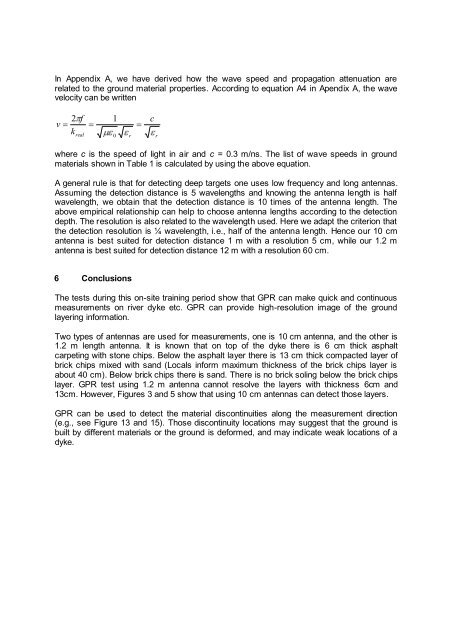
velocity can be written<br />
v<br />
2 f<br />
k<br />
real<br />
1<br />
0<br />
r<br />
c<br />
r<br />
where c is the speed of light in air and c = 0.3 m/ns. The list of wave speeds in ground<br />
materials shown in Table 1 is calculated by using the above equation.<br />
A general rule is that <strong>for</strong> detecting deep targets one uses low frequency and long antennas.<br />
Assuming the detection distance is 5 wavelengths and knowing the antenna length is half<br />
wavelength, we obtain that the detection distance is 10 times of the antenna length. The<br />
above empirical relationship can help to choose antenna lengths according to the detection<br />
depth. The resolution is also related to the wavelength used. Here we adapt the criterion that<br />
the detection resolution is ¼ wavelength, i.e., half of the antenna length. Hence our 10 cm<br />
antenna is best suited <strong>for</strong> detection distance 1 m with a resolution 5 cm, while our 1.2 m<br />
antenna is best suited <strong>for</strong> detection distance 12 m with a resolution 60 cm.<br />
6 Conclusions<br />
The tests during this on-site training period show that <strong>GPR</strong> can make quick and continuous<br />
measurements on <strong>river</strong> <strong>dyke</strong> etc. <strong>GPR</strong> can provide high-resolution image of the ground<br />
layering in<strong>for</strong>mation.<br />
Two types of antennas are used <strong>for</strong> measurements, one is 10 cm antenna, and the other is<br />
1.2 m length antenna. It is known that on top of the <strong>dyke</strong> there is 6 cm thick asphalt<br />
carpeting with stone chips. Below the asphalt layer there is 13 cm thick compacted layer of<br />
brick chips mixed with sand (Locals in<strong>for</strong>m maximum thickness of the brick chips layer is<br />
about 40 cm). Below brick chips there is sand. There is no brick soling below the brick chips<br />
layer. <strong>GPR</strong> test using 1.2 m antenna cannot resolve the layers with thickness 6cm and<br />
13cm. However, Figures 3 and 5 show that using 10 cm antennas can detect those layers.<br />
<strong>GPR</strong> can be used to detect the material discontinuities along the measurement direction<br />
(e.g., see Figure 13 and 15). Those discontinuity locations may suggest that the ground is<br />
built by different materials or the ground is de<strong>for</strong>med, and may indicate weak locations of a<br />
<strong>dyke</strong>.


