

AN1076 - Microchip
AN1076 - Microchip
AN1076 - Microchip

Create successful ePaper yourself
Turn your PDF publications into a flip-book with our unique Google optimized e-Paper software.
<strong>AN1076</strong><br />
However, the use of a second cable is optional.Table 1<br />
shows the physical pinout when a XLR 5-pin connector<br />
is used.<br />
TABLE 1: XLR 5-PIN CONNECTOR<br />
XLR Pin Number DMX 512 Application Function<br />
1 Common Common Reference<br />
2 DMX Data 1-<br />
3 DMX Data 1+<br />
Each DMX512 transmitter sends 512 8-bit dimming values,<br />
between 0 and 255, where 0 represents the lights<br />
off and 255 represents the maximum intensity.<br />
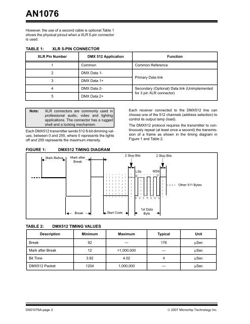
FIGURE 1: DMX512 TIMING DIAGRAM<br />
TABLE 2: DMX512 TIMING VALUES<br />
Primary Data link<br />
4 DMX Data 2- Secondary (Optional) Data link (Unimplemented<br />
for 3 pin XLR connector)<br />
5 DMX Data 2+<br />
Note: XLR connectors are commonly used in<br />
professional audio, video and lighting<br />
applications. The connector has a rugged<br />
shell and a locking mechanism.<br />
Mark Before<br />
Mark after<br />
Break<br />
Break<br />
Start Code<br />
Each receiver connected to the DMX512 line can<br />
choose one of the 512 channels (address selection) to<br />
control its output lamp (load).<br />
The DMX512 protocol requires the transmitter to continuously<br />
repeat (at least once a second) the transmission<br />
of a frame as shown in the timing diagram in<br />
Figure 1 and Table 2.<br />
2 Stop Bits<br />
LSb MSb<br />
0 7<br />
0 1 1 0 1 0 1<br />
1st Data<br />
Byte<br />
2 Stop Bits<br />
Other 511 Bytes<br />
Description Minimum Maximum Typical Unit<br />
Break 92 — 176 μSec<br />
Mark after Break 12


