

AN1076 - Microchip
AN1076 - Microchip
AN1076 - Microchip

You also want an ePaper? Increase the reach of your titles
YUMPU automatically turns print PDFs into web optimized ePapers that Google loves.
<strong>AN1076</strong><br />
TRANSMITTER APPLICATION DEMO:<br />
DIMMING A LAMP<br />
In the previous section we saw that it is very easy to<br />
generate a DMX512 packet using a PIC18F device. In<br />
this demonstration application, we will use a potentiometer<br />
connected to the DMX512 transmitter to control<br />
remotely a lamp attached to a standard DMX512<br />
receiver.<br />
The PIC18F24J10 has a 10-bit Analog-to-Digital Converter<br />
module with 13 inputs. The potentiometer can be<br />
connected on pin RA0 of the MCU corresponding to the<br />
analog input channel 0.<br />
Since the potentiometer won’t change very rapidly,<br />
sampling it every 10 mSec is sufficient.To generate an<br />
automatic and periodic activation of the Analog-to-<br />
Digital Converter, a convenient feature of the<br />
PIC18F24J10 microcontroller can be used. The ADC<br />
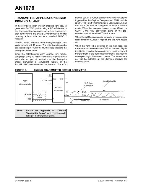
FIGURE 5: DMX512 TRANSMITTER CIRCUIT SCHEMATIC<br />
PIC ®<br />
Microcontroller<br />
RC6/Tx<br />
RC5<br />
100 Ω<br />
0.1 μF<br />
5 V<br />
VCC<br />
RS-485<br />
Transceiver<br />
(-) B<br />
(+) A<br />
Tx<br />
GND<br />
Note: Please see Appendix A: “DMX512<br />
Transmitter Demo” for a complete code<br />
listing of the transmitter demo.<br />
module can, in fact, start periodically a new conversion<br />
triggered by the Capture Compare and PWM module<br />
(CCP). The 16-bit Timer1 module is used in conjunction<br />
with the CCP module configured in 16-bit Compare<br />
mode. When the compare trigger occurs (Timer1 =<br />
CCPR1), the ADC conversion starts on the preselected<br />
input channel and Timer1 is reset.<br />
When the ADC conversion is complete a new result is<br />
loaded into the ADRESH register and the ADIF flag is<br />
set.<br />
When the ADIF bit is detected in the main loop, the<br />
transmitter will retrieve from ADRESH the Most Significant<br />
8 bits encoding the potentiometer position and will<br />
transfer them to the transmission buffer at the position<br />
corresponding to the desired channel. The same channel<br />
will be selected at the dimming receiver for<br />
demonstration.<br />
XLR 3-pin<br />
Connector<br />
To Receiver<br />
DS01076A-page 6 © 2007 <strong>Microchip</strong> Technology Inc.<br />
2<br />
3<br />
1<br />
DMX-<br />
DMX +<br />
COMMON<br />
Shielded cable


