INSTRUCTION MANUAL CyberScan pH/Ion 510 - Welcome to ...
INSTRUCTION MANUAL CyberScan pH/Ion 510 - Welcome to ...
INSTRUCTION MANUAL CyberScan pH/Ion 510 - Welcome to ...

You also want an ePaper? Increase the reach of your titles
YUMPU automatically turns print PDFs into web optimized ePapers that Google loves.
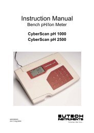
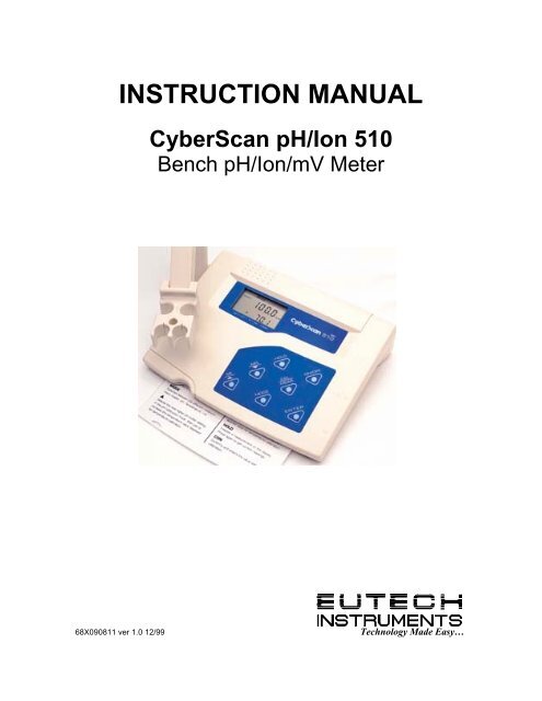
<strong>INSTRUCTION</strong> <strong>MANUAL</strong><br />
<strong>CyberScan</strong> <strong>pH</strong>/<strong>Ion</strong> <strong>510</strong><br />
Bench <strong>pH</strong>/<strong>Ion</strong>/mV Meter<br />
68X090811 ver 1.0 12/99 Technology Made Easy…
PREFACE<br />
Thank you for choosing Eutech Instruments’ <strong>CyberScan</strong> <strong>pH</strong> <strong>510</strong> <strong>pH</strong>/mV/Temperature or <strong>CyberScan</strong><br />
<strong>Ion</strong> <strong>510</strong> <strong>Ion</strong>/<strong>pH</strong>/mV/Temperature bench meter.<br />
The instruction manual functions in two ways: firstly as a step-by-step guide <strong>to</strong> help you operate the<br />
<strong>CyberScan</strong> <strong>510</strong> series meter. Secondly, it serves as a handy reference guide.<br />
The instruction manual is written <strong>to</strong> cover as many anticipated applications of the <strong>CyberScan</strong> <strong>pH</strong>/<strong>Ion</strong><br />
<strong>510</strong> Bench meter series as possible. If there are doubts in the use of the instrument, do not hesitate<br />
<strong>to</strong> contact the nearest Eutech Instruments Authorized Distribu<strong>to</strong>r or Eutech Instruments at (65) 778-<br />
6876 or E-mail at marketing@eutechinst.com.<br />
Kindly remember <strong>to</strong> fill in the warranty card and mail back <strong>to</strong> your authorized distribu<strong>to</strong>r.<br />
Eutech Instruments cannot accept any responsibility for any damage or malfunction <strong>to</strong> the meter<br />
caused by improper use of the instrument.<br />
Note: Eutech Instruments Pte Ltd. reserves the right <strong>to</strong> make improvements in design,<br />
construction, and appearance of our products without notice.<br />
Copyright © 1999 Eutech Instruments Pte. Ltd. All rights reserved. Version 1.0 on 12/99
<strong>CyberScan</strong> <strong>pH</strong> <strong>510</strong>/<strong>Ion</strong> <strong>510</strong><br />
TABLE OF CONTENTS<br />
1 INTRODUCTION .............................................................................................................................. 3<br />
1.1 Introducing the <strong>CyberScan</strong> Series ............................................................................................................3<br />
1.2 Cus<strong>to</strong>m LCD .............................................................................................................................................3<br />
1.3 Keypad......................................................................................................................................................3<br />
1.4 Rear Instrument Panel..............................................................................................................................4<br />
2 STARTING UP ................................................................................................................................. 5<br />
2.1 Connecting the Sensor Electrode .............................................................................................................5<br />
2.2 Connecting the Temperature Probe..........................................................................................................5<br />
2.3 Connecting the A/C Adapter .....................................................................................................................5<br />
2.4 Connecting the Chart Recorder ................................................................................................................5<br />
2.5 Connecting the Electrode Holder (Optional) .............................................................................................5<br />
2.6 Steps Prior <strong>to</strong> Calibration..........................................................................................................................6<br />
2.6.1 Switching ‘ON’ and ‘OFF’ the meter..................................................................................................6<br />
2.6.2 Selecting Measurement Mode ..........................................................................................................6<br />
2.6.3 Meter Reset ......................................................................................................................................6<br />
2.6.4 Selecting <strong>pH</strong> Buffer Standard ...........................................................................................................6<br />
3 CALIBRATION................................................................................................................................. 7<br />
3.1 <strong>pH</strong> Calibration ...........................................................................................................................................7<br />
3.2 <strong>Ion</strong> Concentration Calibration (For <strong>Ion</strong> <strong>510</strong> only) ......................................................................................9<br />
3.3 mV Calibration ........................................................................................................................................10<br />
3.4 Temperature Calibration .........................................................................................................................11<br />
4 MEASUREMENT ........................................................................................................................... 12<br />
4.1 Au<strong>to</strong>matic Temperature Compensation (ATC)........................................................................................12<br />
4.2 Manual Temperature Compensation (MTC) ...........................................................................................12<br />
4.3 Taking Measurements ............................................................................................................................12<br />
4.4 HOLD Function .......................................................................................................................................13<br />
4.5 S<strong>to</strong>ring and Recalling Data from Memory ...............................................................................................13<br />
5 SETUP FUNCTIONS...................................................................................................................... 15<br />
5.1 P1.0 Clear Memory................................................................................................................................15<br />
5.2 P2.0 Viewing Electrode Diagnosis ........................................................................................................16<br />
5.3 P3.0 Selecting <strong>pH</strong> Buffer Standard ........................................................................................................17<br />
5.4 P4.0 Meter Reset...................................................................................................................................17<br />
6 <strong>pH</strong> Electrode Maintenance........................................................................................................... 18<br />
6.1 S<strong>to</strong>rage ...................................................................................................................................................18<br />
6.2 After Use.................................................................................................................................................18<br />
6.2.1 Electrolyte Replacement (for refillable electrodes only) ..................................................................18<br />
6.3 Electrode Cleaning .................................................................................................................................18<br />
6.4 <strong>pH</strong> Electrode Rejuvenation .....................................................................................................................19<br />
6.4.1 Rejuvenation Procedure .................................................................................................................19<br />
7 TROUBLESHOOTING GUIDE....................................................................................................... 20<br />
7.1 Error Messages ......................................................................................................................................20<br />
7.2 Troubleshooting ......................................................................................................................................20<br />
8 ADDITIONAL INFORMATION ....................................................................................................... 21<br />
8.1 <strong>pH</strong> and Temperature...............................................................................................................................21<br />
8.2 Use of Standard <strong>pH</strong> Buffers....................................................................................................................21<br />
8.3 Standard <strong>pH</strong> Buffers ...............................................................................................................................21<br />
8.4 List of Accessories..................................................................................................................................22<br />
8.4.1 <strong>pH</strong> Buffers/Sachets, Reference Electrolyte & Others......................................................................22<br />
8.4.2 <strong>Ion</strong> Selective Electrodes (ISE) ........................................................................................................22<br />
8.4.3 <strong>pH</strong> & ORP Electrodes .....................................................................................................................23<br />
8.5 Specifications..........................................................................................................................................24<br />
8.6 Warranty .................................................................................................................................................24<br />
8.6.1 Return of Items ...............................................................................................................................24<br />
2
<strong>CyberScan</strong> <strong>pH</strong> <strong>510</strong>/<strong>Ion</strong> <strong>510</strong><br />
1 INTRODUCTION<br />
1.1 Introducing the <strong>CyberScan</strong> Series<br />
The Eutech Instruments’ <strong>CyberScan</strong> <strong>pH</strong> <strong>510</strong> and <strong>CyberScan</strong> <strong>Ion</strong> <strong>510</strong> bench meters are microprocessor-based<br />
which incorporates new ASIC (Application Specific Integrated Circuit). It is designed with many advanced userfriendly<br />
features with the convenience of users in mind. The meters are capable of s<strong>to</strong>ring and recalling up <strong>to</strong><br />
50 data sets in its non-volatile memory. In addition, as a space saver, an optional swivel electrode holder can<br />
be attached at the either side of bench meter for resting the electrodes and probes during operation.<br />
The <strong>CyberScan</strong> <strong>pH</strong> <strong>510</strong> meter is capable of measuring <strong>pH</strong>/ORP with Temperature; while the <strong>CyberScan</strong> <strong>Ion</strong><br />
<strong>510</strong> meter measures <strong>Ion</strong> Concentration/<strong>pH</strong>/ORP with temperature. It is equipped with a large cus<strong>to</strong>mized LCD<br />
(Liquid Crystal Display) with simultaneous display of the measured values for easy reading. It is most ideal for<br />
routine <strong>pH</strong>/<strong>Ion</strong> Concentration measurement in indoor applications.<br />
1.2 Cus<strong>to</strong>m LCD<br />
The <strong>CyberScan</strong> <strong>510</strong> meter is characterized by a large cus<strong>to</strong>m dual LCD. The display has mode annuncia<strong>to</strong>rs<br />
for <strong>pH</strong>, mV, ppm and temperature readings. The secondary (lower) display shows the temperature reading<br />
simultaneously with the primary (upper) display that shows the measured values of <strong>pH</strong>, ppm or mV. Special<br />
annuncia<strong>to</strong>rs such as units of measure, error message, graphical icons and modes of operation are arranged<br />
around both primary and secondary display <strong>to</strong> give you a comprehensive yet uncluttered display.<br />
SETUP – The meter<br />
is in SETUP mode.<br />
READY - The measured<br />
value has stabilized.<br />
HOLD - The displayed<br />
value has been frozen.<br />
ERR - An error in<br />
operation has occured.<br />
Buffer - Prompts user<br />
<strong>to</strong> select buffer during<br />
calibration, or indicates<br />
buffer error when<br />
flashing <strong>to</strong>gether with<br />
the ERR annuncia<strong>to</strong>r.<br />
1.3 Keypad<br />
MEAS- The instrument is in<br />
the measurement mode.<br />
SETUP<br />
READY<br />
HOLD<br />
MEAS<br />
ON<br />
OFF MEM<br />
ERR<br />
ELECTRODE - indicates<br />
electrode error when it<br />
appears with ERR.<br />
AM PM<br />
CAL- The instrument is in<br />
the calibration mode.<br />
3<br />
CAL<br />
MEM<br />
R.mV<br />
<strong>pH</strong><br />
ppm<br />
C F<br />
<strong>pH</strong><br />
ATC<br />
<strong>pH</strong> – Indicates buffer<br />
values of respective<br />
USA or NIST buffer<br />
option set.<br />
MEM- Data is s<strong>to</strong>red<br />
in<strong>to</strong> memory<br />
Shows the<br />
respective mode<br />
of operation.<br />
ATC (Au<strong>to</strong>matic<br />
Temperature<br />
Compensation)<br />
activated. If ATC is not<br />
displayed, temperature<br />
probe is not connected.<br />
In this case the Manual<br />
Temperature<br />
Compensation is<br />
activated.<br />
A large splashproof membrane keypad with tactile feedback makes meter easy <strong>to</strong> use. Names and symbols<br />
describe the function but<strong>to</strong>n controls.<br />
Key Measurement Mode Calibration / Setup Mode<br />
ON/OFF Powers the meter ON/OFF. When the meter is<br />
switched on, it au<strong>to</strong>matically starts in the last<br />
mode of operation.
<strong>CyberScan</strong> <strong>pH</strong> <strong>510</strong>/<strong>Ion</strong> <strong>510</strong><br />
CAL/MEAS Toggles between the measurement and<br />
calibration modes of the meter. In SETUP<br />
mode, pressing CAL/MEAS key returns <strong>to</strong> the<br />
measurement mode.<br />
MODE Toggles between the different measurement<br />
modes available <strong>pH</strong>/Temperature/mV/<strong>Ion</strong>.<br />
MI/▲ MI inputs measurements in<strong>to</strong> memory and<br />
scrolls through memory values.<br />
MR/▼ MR recalls measurements from memory and<br />
scrolls through memory values.<br />
HOLD Freezes a measurement on the display. Press<br />
again <strong>to</strong> get current readings.<br />
4<br />
Switches from <strong>pH</strong> <strong>to</strong> Temperature in <strong>pH</strong><br />
calibration mode<br />
▲ scrolls values in mV calibration mode<br />
and selects temperature values and ion<br />
options in calibration mode. Scrolls <strong>to</strong><br />
next program in the SETUP mode.<br />
▼ scrolls values in mV calibration mode<br />
and selects temperature values and ion<br />
options in calibration Scrolls <strong>to</strong> next<br />
program in the SETUP mode.<br />
ENTER Enter functions in the memory mode. Confirms and enters the value selected<br />
for calibration.<br />
You can also configure functions like Meter Reset, Memory Clear and Selection of <strong>pH</strong> Buffer Standard via its<br />
keypad. Please refer <strong>to</strong> Section 5 for more information on the above functions.<br />
1.4 Rear Instrument Panel<br />
The <strong>CyberScan</strong> <strong>510</strong> series meter provides a complete set of connec<strong>to</strong>rs for the various accessories commonly<br />
used. Listed in the table are the details of the connections that you can make.<br />
Rear View of Meter<br />
Connection Function<br />
ATC For phono jack connection from the temperature probe for Au<strong>to</strong>matic Temperature<br />
compensation. The probe should be a 30KΩ thermister type.<br />
INPUT For connection <strong>to</strong> sensor electrodes with BNC type connec<strong>to</strong>rs. The meter accepts any <strong>pH</strong>,<br />
ORP or ISE with BNC connec<strong>to</strong>r. Always ensure that the connec<strong>to</strong>r is clean and dry.<br />
REF For connection <strong>to</strong> pin type reference electrode normally used with half cell (mono) type <strong>pH</strong><br />
electrodes or ISEs.<br />
REC For connection <strong>to</strong> strip chart recorders. Use subminiature plug with positive tip.<br />
GND For connection <strong>to</strong> the ground earth jack (standard tip connec<strong>to</strong>rs).<br />
DC For connection for the AC/DC power adapter (optional accessory – see section on<br />
Specifications for details)
<strong>CyberScan</strong> <strong>pH</strong> <strong>510</strong>/<strong>Ion</strong> <strong>510</strong><br />
2 STARTING UP<br />
Connect the accessory connec<strong>to</strong>rs at the rear of the instrument panel. During operation, it is important that<br />
water does not get on<strong>to</strong> the BNC connec<strong>to</strong>r. Also avoid <strong>to</strong>uching the connec<strong>to</strong>r with soiled or wet hands.<br />
2.1 Connecting the Sensor Electrode<br />
Slide the electrode connec<strong>to</strong>r of the electrode over the socket of the meter’s BNC connec<strong>to</strong>r marked ‘INPUT’.<br />
The meter can accept any standard <strong>pH</strong>, ORP, or <strong>Ion</strong> Selective Electrode with a BNC connec<strong>to</strong>r. Align the slot<br />
of the electrode connec<strong>to</strong>r with the posts of the socket. Rotate the connec<strong>to</strong>r clockwise until it locks. For<br />
separate reference electrodes, push the electrode pin in<strong>to</strong> jack marked ‘REF’.<br />
2.2 Connecting the Temperature Probe<br />
Insert the temperature probe (provided) in<strong>to</strong> the connec<strong>to</strong>r marked ‘ATC’.<br />
2.3 Connecting the A/C Adapter<br />
Slide in the adapter jack of the A/C adapter in<strong>to</strong> the back panel marked ‘DC’ until it is firmly seated. Ensure that<br />
the power is switched off before installation and correct voltage of adapter is used.<br />
2.4 Connecting the Chart Recorder<br />
You can connect chart recorders or external output devices for continuous prin<strong>to</strong>ut. Plug in the input connec<strong>to</strong>r<br />
and ground pin of the chart recorder in<strong>to</strong> the ports marked ‘REC’ and ‘GND’ respectively.<br />
Temp. probe<br />
Sensor electrode<br />
Separate ref. electrode<br />
2.5 Connecting the Electrode Holder (Optional)<br />
The integral electrode holder serves as a handy holder<br />
for mounting a few <strong>pH</strong>/<strong>Ion</strong> electrodes or a temperature<br />
probe during measurement or when idle.<br />
The <strong>CyberScan</strong> bench meter’s base plate has a side<br />
metal bar <strong>to</strong> which you can attach an integral swivel<br />
electrode holder. You can mount the electrode holder<br />
on either right or left side of the meter.<br />
To position the electrode arm:<br />
Use a Phillips screwdriver <strong>to</strong> remove the screw holding<br />
the electrode holder. Slide the side metal bar until the<br />
second screw slot lines up with the original screw<br />
hole. Use the screw removed earlier <strong>to</strong> secure the<br />
electrode holder in<strong>to</strong> position. Note the side metal bar<br />
is reversible. If desired, remove screw holding<br />
electrode holder base and slide out of brackets, Slide<br />
base in<strong>to</strong> brackets on opposite side and tighten screw.<br />
5<br />
Chart recorder<br />
Ground<br />
AC/DC Adapter<br />
Bot<strong>to</strong>m of Meter
<strong>CyberScan</strong> <strong>pH</strong> <strong>510</strong>/<strong>Ion</strong> <strong>510</strong><br />
Electrode Arm<br />
Side Metal Bar<br />
2.6 Steps Prior <strong>to</strong> Calibration<br />
2.6.1 Switching ‘ON’ and ‘OFF’ the meter<br />
Press ON key <strong>to</strong> switch meter on. All the LCD segments will display momentarily for a few seconds and the<br />
LCD then switches <strong>to</strong> the last measurement mode. To switch meter off, press OFF key.<br />
2.6.2 Selecting Measurement Mode<br />
The measurement modes available for the <strong>CyberScan</strong> <strong>pH</strong> <strong>510</strong> meter are <strong>pH</strong>, mV (for ORP) and Temperature,<br />
while the <strong>CyberScan</strong> <strong>Ion</strong> <strong>510</strong> meter has <strong>Ion</strong>, <strong>pH</strong>, mV and Temperature measurement modes. Select the correct<br />
mode of operation by pressing the MODE key, and each press takes you <strong>to</strong> next measurement mode. When<br />
selecting a particular parameter the respective mode annuncia<strong>to</strong>r displays at the right hand side of primary<br />
display; these include [<strong>pH</strong>] for <strong>pH</strong>, [ o C] for Temperature, [ppm] for <strong>Ion</strong> Concentration and [mV] for Millivolt.<br />
2.6.3 Meter Reset<br />
On first use, it is not necessary <strong>to</strong> reset meter before calibration as it has been fac<strong>to</strong>ry-calibrated. However if<br />
you wish <strong>to</strong> reset the meter <strong>to</strong> fac<strong>to</strong>ry default refer <strong>to</strong> this Section 5.4. Note re-calibration of meter is required<br />
before measurement after the meter is reset.<br />
Likewise if you wish <strong>to</strong> prepare a new set of measurement, you may reset all the last calibrated <strong>pH</strong> values for<br />
added convenience. Caution: All calibration values and memory data will be erased upon activation. Recalibration<br />
is required.<br />
2.6.4 Selecting <strong>pH</strong> Buffer Standard<br />
To install electrode arm <strong>to</strong> the meter:<br />
To mount the electrode arm in<strong>to</strong> the metal rod on the side<br />
bar, align the slot with the metal rod and base of electrode<br />
arm. Push it downwards until it fully sits in<strong>to</strong> position. Avoid<br />
using excessive force when fixing or removing. The<br />
electrode arm is ready for use.<br />
The meter is capable of calibrating based on either USA or NIST <strong>pH</strong> buffer standards. Please refer <strong>to</strong> Section<br />
5.3 P3.0 for details on how <strong>to</strong> change the USA buffer standard <strong>to</strong> the NIST standard on the meter itself. Refer<br />
<strong>to</strong> Section 8.4.1 for more details on <strong>pH</strong> buffer standards available.<br />
NOTE: Remove protective rubber cap or s<strong>to</strong>rage bottle (if any) of the electrode before proceeding with<br />
measurement or calibration. Take care not <strong>to</strong> exert <strong>to</strong>o much force as this may cause damage <strong>to</strong> the electrode.<br />
Whenever the electrode is not in use, put it in<strong>to</strong> s<strong>to</strong>rage bottle or rubber cap provided. Refer <strong>to</strong> the Section 6<br />
on Probe Maintenance for more details.<br />
6
<strong>CyberScan</strong> <strong>pH</strong> <strong>510</strong>/<strong>Ion</strong> <strong>510</strong><br />
3 CALIBRATION<br />
3.1 <strong>pH</strong> Calibration<br />
The <strong>CyberScan</strong> <strong>510</strong> series bench meter is capable of multi-point calibration (up <strong>to</strong> 3 points) for unprecedented<br />
accuracy across the measurement range. The 3-point calibration offers flexibility of calibrating using either USA<br />
or NIST buffer standards with their 3 internationally accepted calibration points namely:<br />
USA standard buffer options: <strong>pH</strong> 4.01, <strong>pH</strong> 7.00 and <strong>pH</strong> 10.01<br />
NIST standard buffer options: <strong>pH</strong> 4.01, <strong>pH</strong> 6.86 and <strong>pH</strong> 9.18.<br />
For ATC measurements, attach the temperature probe <strong>to</strong> the meter. The ATC mode annuncia<strong>to</strong>r shows on the<br />
display. Insert the probe in<strong>to</strong> the solution <strong>to</strong> be measured so that the sample temperature can be recorded and<br />
<strong>pH</strong> readings au<strong>to</strong>matically temperature compensated. If manual temperature compensation is preferred, do not<br />
plug a temperature probe in<strong>to</strong> the meter.<br />
DO NOT REUSE SOLUTIONS AFTER CALIBRATION. Contaminants in the solution can affect the calibration,<br />
and eventually the accuracy of the measurements. All new calibrations will override existing s<strong>to</strong>red calibration<br />
data at these calibration points.<br />
It is recommended that you perform at least a 2-point calibration using buffers that bracket (one above and one<br />
below) the expected sample range, starting with <strong>pH</strong> 7 buffer firstly. You can perform a 1-point calibration, but<br />
make sure that the buffer value is close <strong>to</strong> the sample value you are measuring. Select a <strong>pH</strong> 4, 7 or 10 buffer in<br />
sachets or bottles from Eutech standard buffer solutions.<br />
1. Press ON/OFF key. All the LCD segments will be displayed<br />
momentarily. The LCD switches <strong>to</strong> <strong>pH</strong> measurement mode. If<br />
necessary press MODE key <strong>to</strong> select <strong>pH</strong> mode.<br />
NOTE: The meter starts in the same measurement mode that it<br />
was switched off.<br />
2. The cus<strong>to</strong>mized LCD display will indicate the following:<br />
Display Remarks<br />
MEAS Measurement mode is selected<br />
<strong>pH</strong> Unit of measurement<br />
o<br />
C Measured temperature reading<br />
ATC Au<strong>to</strong>matic Temperature Compensation<br />
3. Rinse both <strong>pH</strong> electrode and temperature probe well with<br />
deionized water or rinse solution. (Do not wipe the electrode as<br />
this may cause a build-up of electrostatic charge on the<br />
glass surface!).<br />
One Point Calibration<br />
4. Select the first <strong>pH</strong> buffer, say <strong>pH</strong> 7.00 buffer and pour some in<strong>to</strong> a<br />
clean container.<br />
5. Dip both probes in<strong>to</strong> the standard calibration buffer. The end of<br />
the probe must be completely immersed in<strong>to</strong> the buffer. Stir the<br />
probes gently <strong>to</strong> create a homogenous solution.<br />
6. Press CAL/MEAS key <strong>to</strong> enter the <strong>pH</strong> calibration mode. The<br />
annuncia<strong>to</strong>r [CAL] appears on <strong>to</strong>p of the LCD <strong>to</strong> indicate the<br />
meter is in <strong>pH</strong> calibration mode. The upper display will show the<br />
measured reading while the lower display indicates appropriate<br />
<strong>pH</strong> standard buffer solution being used.<br />
NOTE: The meter au<strong>to</strong>matically recognizes the buffers in the<br />
buffer standard you have set in the SETUP mode, i.e. either USA<br />
(<strong>pH</strong> 4.01, 7.00 or 10.01) or NIST (<strong>pH</strong> 4.01, 6.86 or 9.18) buffers.<br />
NOTE: To exit from <strong>pH</strong> calibration mode without confirming<br />
calibration, DO NOT press ENTER key in step 9. Press the<br />
CAL/MEAS key instead.<br />
7<br />
Figure 1: 1st-point calibration
<strong>CyberScan</strong> <strong>pH</strong> <strong>510</strong>/<strong>Ion</strong> <strong>510</strong><br />
Figure 2: Calibration error<br />
Figure 3: 2nd-point calibration<br />
Figure 4: 3rd- point calibration<br />
HINT: If the selected<br />
buffer value is not within<br />
the accepted window (see<br />
below) from the measured<br />
value: the electrode and<br />
buffer icon blink and ERR<br />
annuncia<strong>to</strong>r appears next<br />
<strong>to</strong> the secondary display.<br />
(See Figure 2 above)<br />
Press CAL/MEAS key <strong>to</strong><br />
exit the ERR condition.<br />
Window of Accepted<br />
Values:-<br />
USA 4.01 ±1.00<br />
7.00 ±1.50<br />
10.01 ±1.00<br />
−−−−−−−−−−−−−−−−−−−−<br />
−−−−−−−−−−−−−−−−−−−−<br />
NIST 4.01 ±1.00<br />
6.86 ±1.25<br />
9.18 ±1.00<br />
7. Wait for the measured <strong>pH</strong> value <strong>to</strong> stabilize (when the [READY]<br />
indica<strong>to</strong>r displays in the left-hand corner).<br />
8. If the upper measured display is not within the buffer acceptable<br />
window (refer <strong>to</strong> Hint below) an error message and the<br />
electrode icon flash upon pressing the ENTER key. Refer <strong>to</strong><br />
Section 7 on Troubleshooting Guide. Check electrode condition<br />
and recalibrate. Press CAL/MEAS key <strong>to</strong> exit calibration and<br />
resume <strong>to</strong> the measurement mode.<br />
9. Press the ENTER key. The upper display flashes the calibration<br />
value momentarily. The calibration point is successfully s<strong>to</strong>red<br />
in the meter.<br />
10. If you are performing a one-point calibration, press CAL/MEAS<br />
key <strong>to</strong> return <strong>to</strong> the measurement mode and start taking <strong>pH</strong><br />
readings (see Figure 1).<br />
Two <strong>to</strong> Third Point Calibration<br />
11. If you are performing a multi-point calibration (i.e. second-point<br />
or more) go <strong>to</strong> step 12.<br />
12. Rinse the probes with deionized water or rinse solution <strong>to</strong> avoid<br />
cross contamination, and place them in the next <strong>pH</strong> buffer, say<br />
<strong>pH</strong> 4.01 buffer. The meter au<strong>to</strong>matically switches <strong>to</strong> the next <strong>pH</strong><br />
buffer solution selected in the lower display<br />
13. Wait for the measured <strong>pH</strong> value <strong>to</strong> stabilize (when the [READY]<br />
indica<strong>to</strong>r displays in the left-hand corner). (see Figure 3).<br />
14. Press the ENTER key. The upper display flashes the calibrated<br />
value. The calibration point is now s<strong>to</strong>red in the meter.<br />
15. If you are performing a two-point calibration, then press the<br />
CAL/MEAS key <strong>to</strong> return <strong>to</strong> the measurement mode and start<br />
taking <strong>pH</strong> readings.<br />
16. If you are performing a three-point calibration go <strong>to</strong> step 17.<br />
17. Rinse the probes with deionized water or rinse solution, and<br />
place them in the next <strong>pH</strong> buffer, say <strong>pH</strong> 10.01 buffer. The<br />
meter au<strong>to</strong>matically switches <strong>to</strong> the next <strong>pH</strong> buffer solution<br />
selected in the lower display.<br />
18. Wait for the measured <strong>pH</strong> value <strong>to</strong> stabilize (when the [READY]<br />
indica<strong>to</strong>r displays in the left-hand corner) (see Figure 4).<br />
19. Press the ENTER key. The upper display flashes the calibration<br />
value. The calibration point is now s<strong>to</strong>red in the meter. The<br />
meter au<strong>to</strong>matically returns <strong>to</strong> the <strong>pH</strong> measurement mode after<br />
a three-point calibration is performed.<br />
8
<strong>CyberScan</strong> <strong>pH</strong> <strong>510</strong>/<strong>Ion</strong> <strong>510</strong><br />
3.2 <strong>Ion</strong> Concentration Calibration (For <strong>Ion</strong> <strong>510</strong> only)<br />
The <strong>CyberScan</strong> <strong>Ion</strong> <strong>510</strong> meter is capable of up <strong>to</strong> 3-point ion calibration (minimum 2 point) with choice of 4<br />
options <strong>to</strong> ensure accuracy across the entire measurement range. <strong>Ion</strong> calibration options include 0.10, 1.0,<br />
10.0 or 100.0 ppm. All calibration should be at least one decade apart from each other. For example you may<br />
perform 3 point calibration <strong>to</strong> 0.10, 1.0 and 10.0, or 2-point calibration <strong>to</strong> 10.0 and 100.0. If 1-point calibration is<br />
performed an error message “Er2” is displayed. If any of calibration points are not within 1 decade, an error<br />
message “Er4” will be displayed at the end of calibration process.<br />
Calibration values are successfully s<strong>to</strong>red if the ISE slope is within the specified <strong>to</strong>lerance of 15mV/decade<br />
(minimum) and 90mV/decade (maximum), otherwise an error message “Er3” is displayed (see Figure 7). The<br />
calibration values are not s<strong>to</strong>red in<strong>to</strong> the meter’s built-in memory if any error message appears after each<br />
calibration process. Re-calibration is necessary as calibration is unsuccessfully attempted in this instance.<br />
Check that your ISE and standard solutions are in good working conditions.<br />
Ensure that you use new or fresh standard solutions during calibration. Do not reuse ion standard solution as it<br />
may be contaminated and affect the calibration and accuracy of measurements. Always s<strong>to</strong>re standard<br />
solutions in a dry, cool environment if possible. Before use, remove plastic protective cap of ISE. Briefly rinse<br />
the electrode with clean deionized water <strong>to</strong> remove any residues.<br />
Rinse probes before and after each calibration or sample measurement <strong>to</strong> avoid cross-contamination. For<br />
more details please refer <strong>to</strong> Manufacturer’s care and maintenance guide. Note the <strong>Ion</strong> calibration values will<br />
be lost once power is disconnected; only <strong>pH</strong> and mV calibration values will be retained.<br />
1. Connect an <strong>Ion</strong> Selective Electrode (ISE) <strong>to</strong> the BNC input connec<strong>to</strong>r<br />
on the back of the meter. Turn the meter ON.<br />
2. Press MODE key (if needed) <strong>to</strong> select ion measurement mode. If<br />
there is no old calibration values, then the meter displays “---“ in the<br />
upper display in measurement mode.<br />
3. Dip the ISE in<strong>to</strong> the first calibration standard. Make sure <strong>to</strong> start with<br />
the calibration standard that has the lowest concentration and move<br />
up <strong>to</strong> the standards that have higher concentrations.<br />
Swirl it gently. Press CAL key <strong>to</strong> enter the ion calibration mode. The<br />
[CAL] indica<strong>to</strong>r appears above the upper display and the upper<br />
display reads “0.10”. The lower display shows the corresponding<br />
absolute mV value of sample measured.<br />
4. The first calibration point of 0.10 ppm appears on the display. If you<br />
DO NOT wish <strong>to</strong> calibrate <strong>to</strong> this point, press ▲ (up arrow) <strong>to</strong> skip and<br />
continue <strong>to</strong> the next calibration point of 1.0 ppm or 10.0 ppm.<br />
5. If you DO wish <strong>to</strong> calibrate <strong>to</strong> 0.10 ppm, allow the mV reading <strong>to</strong><br />
stabilize. When the reading stabilizes the [READY] indica<strong>to</strong>r will<br />
appear on the display. Stabilization may take a few minutes<br />
depending on electrode and standard concentration.<br />
6. Press ENTER key <strong>to</strong> confirm your first point calibration (see Figure 5).<br />
After calibration, the display will show the next calibration option, i.e.<br />
1.0 ppm. Proceed by rinsing the electrode with deionized water<br />
before placing it in the next calibration standard i.e. 1.0 ppm.<br />
7. Allow the meter <strong>to</strong> stabilize in the next calibration standard. Wait for<br />
the [READY] indica<strong>to</strong>r <strong>to</strong> appear before you press the ENTER key <strong>to</strong><br />
confirm the second calibration point. The upper display flashes<br />
momentarily then moves <strong>to</strong> the next calibration point of 10.0 ppm.<br />
NOTE: If you are performing a 2-point ion calibration, press<br />
CAL/MEAS key. “SLO” appears in the upper display with the [mV]<br />
indica<strong>to</strong>r and the number in the lower display is the electrode slope in<br />
mV (see Figure 6). You are ready <strong>to</strong> take ion measurements. If the<br />
slope is outside the acceptable limits or if incorrect standards have<br />
been used the upper display will show “Er3”.<br />
9<br />
Figure 5: 1st-point calibration
<strong>CyberScan</strong> <strong>pH</strong> <strong>510</strong>/<strong>Ion</strong> <strong>510</strong><br />
If you are performing a 3-point calibration, rinse off the electrode<br />
with deionized water and place it in the next calibration standard<br />
and proceed as described earlier.<br />
8. Allow meter <strong>to</strong> stabilize in the next calibration standard. Wait for the<br />
[READY] indica<strong>to</strong>r <strong>to</strong> appear before you press the ENTER key <strong>to</strong><br />
confirm the third calibration point. The upper display flashes for a<br />
few seconds then “SLO” appears in the upper display with the mV<br />
indica<strong>to</strong>r, the number in the lower display is the average electrode<br />
slope in mV (see Figure 6). After a few seconds the meter reverts<br />
<strong>to</strong> the measurement mode. You are now ready <strong>to</strong> take ion<br />
measurement.<br />
NOTE: All the calibration values are successfully s<strong>to</strong>red. Otherwise<br />
error message will appear in the LCD if the calibration was<br />
unsuccessful with no values s<strong>to</strong>red in<strong>to</strong> memory.<br />
NOTE: You may compare the average electrode slope value with<br />
the expected slope value for your electrode from your electrode<br />
manual <strong>to</strong> verify electrode operation.<br />
3.3 mV Calibration<br />
1. Make sure the meter is on and if necessary, press the MODE key <strong>to</strong><br />
select mV mode. The [mV] indica<strong>to</strong>r appears in the upper right-hand<br />
corner of the display.<br />
2. Press the CAL/MEAS key. The [CAL] indica<strong>to</strong>r appears above the<br />
upper display that displays the relative mV reading. The lower<br />
display shows the absolute mV value.<br />
NOTE: If you have never calibrated relative mV or if the meter has<br />
been reset, the value shown in the upper display is the same as the<br />
absolute mV value. The range of adjustment is -1999 mV <strong>to</strong> 1999<br />
mV (resolution is 1 mV); of which from -199.9 <strong>to</strong> 199.9 mV the meter<br />
gives you a resolution of 0.1 mV.<br />
3. Press ▲ or ▼ keys <strong>to</strong> enter the relative mV value that matches your<br />
desired reading.<br />
4. Press the ENTER key <strong>to</strong> confirm the reading and the meter<br />
au<strong>to</strong>matically returns <strong>to</strong> the measurement mode. The upper display<br />
now shows the relative mV reading. The [R.mV] indica<strong>to</strong>r appears in<br />
the upper right hand corner.<br />
NOTE: New mV calibrations will override existing s<strong>to</strong>red mV<br />
calibration data. The meter retains s<strong>to</strong>red mV calibrations even when<br />
the meter is turned off.<br />
10<br />
HINT: Minimum of 2<br />
points and maximum<br />
of 3 points are<br />
allowed for <strong>Ion</strong><br />
Calibration. All<br />
calibration points<br />
should be at least one<br />
decade apart, i.e.<br />
valid calibration<br />
points are 0.1, 1, 10<br />
ppm or 1, 10, 100 ppm<br />
or 0.1, 1 ppm or 1, 10<br />
ppm or 10, 100 ppm.<br />
Figure 6: Slope value in mV<br />
Figure 7: Error message Er3<br />
if slope not within range
<strong>CyberScan</strong> <strong>pH</strong> <strong>510</strong>/<strong>Ion</strong> <strong>510</strong><br />
3.4 Temperature Calibration<br />
In this calibration procedure, the ATC probe is attached <strong>to</strong> the meter and the [ATC] annuncia<strong>to</strong>r is displayed on<br />
the right hand side of the LCD.<br />
1. Dip the temperature probe in<strong>to</strong> a solution of known temperature,<br />
such as a temperature bath for a few minutes until the temperature<br />
probe stabilizes.<br />
2. To perform temperature calibration, you must be in the <strong>pH</strong><br />
measurement mode.<br />
3. Press MODE key <strong>to</strong> switch <strong>to</strong> the <strong>pH</strong> measurement mode if you are<br />
in the mV or ion measurement modes.<br />
4. Press CAL/MEAS key <strong>to</strong> enter <strong>pH</strong> calibration mode.<br />
5. Press MODE key again <strong>to</strong> switch <strong>to</strong> temperature calibration.<br />
6. Press ▲ or ▼ key <strong>to</strong> scroll <strong>to</strong> the correct temperature value<br />
corresponding <strong>to</strong> the known solution temperature. The meter allows<br />
a limit of ± 5 o C variation (with 0.1 o C resolution) of the input<br />
reading, and of the original displayed reading.<br />
7. Once you selected the correct temperature, press ENTER key <strong>to</strong><br />
confirm. The meter au<strong>to</strong>matically returns <strong>to</strong> the <strong>pH</strong> measurement<br />
mode.<br />
11
<strong>CyberScan</strong> <strong>pH</strong> <strong>510</strong>/<strong>Ion</strong> <strong>510</strong><br />
4 MEASUREMENT<br />
4.1 Au<strong>to</strong>matic Temperature Compensation (ATC)<br />
For ATC measurements, simply attach the temperature probe in<strong>to</strong> the<br />
meter (see Section 2.2). The [ATC] annuncia<strong>to</strong>r lights up on the LCD.<br />
NOTE: If you are using a temperature probe, the probe must be<br />
submersed in the liquid you are measuring so that the sample<br />
temperature can be recorded and compensated for.<br />
4.2 Manual Temperature Compensation (MTC)<br />
Important: For MTC, you must disconnect the temperature probe.<br />
1. Switch the meter on. Press the MODE key <strong>to</strong> select <strong>pH</strong> mode.<br />
2. Press the CAL/MEAS key <strong>to</strong> enter <strong>pH</strong> calibration mode. The CAL<br />
annunica<strong>to</strong>r appears above the upper display.<br />
3. While in <strong>pH</strong> calibration mode, press the MODE key <strong>to</strong> enter<br />
temperature compensation mode. The upper display shows the<br />
current temperature setting and the lower display shows the default<br />
value 25.0 ºC (if the meter has never been manually set for<br />
temperature) or the last manually set value if the meter has<br />
previously set for MTC. If you have not set the current temperature<br />
setting the upper display will also show the default value of 25.0 ºC.<br />
4. Check the temperature of your sample using an accurate<br />
thermometer.<br />
5. Press ▲ or ▼ key <strong>to</strong> offset the temperature <strong>to</strong> the measured value<br />
from step 4.<br />
6. Press ENTER key <strong>to</strong> confirm the selected temperature and return <strong>to</strong><br />
the <strong>pH</strong> measurement mode.<br />
7. To exit this program without confirming the MTC value, DO NOT<br />
press ENTER key in step 6. Press CAL/MEAS key instead.<br />
NOTE: The meter will compensate <strong>pH</strong> reading for the manually set<br />
temperature.<br />
4.3 Taking Measurements<br />
Be sure <strong>to</strong> remove the electrode soaker bottle or protective rubber cap on the electrode before measurement.<br />
To take readings:<br />
1. Rinse the electrode with distilled or tap water before use <strong>to</strong> remove any impurities adhering <strong>to</strong> the<br />
electrode body. If the <strong>pH</strong> electrode had dehydrated, soak it for 30 minutes in EC-RE005 electrode s<strong>to</strong>rage<br />
solution. (See Electrode Care - Section 6)<br />
2. Press ON key <strong>to</strong> switch on meter. The [MEAS] annuncia<strong>to</strong>r appears on the <strong>to</strong>p center of LCD. The ATC<br />
annuncia<strong>to</strong>r appears in the lower right hand corner <strong>to</strong> indicate ATC if a temperature probe is plugged.<br />
(For MTC, refer <strong>to</strong> Section 4.2).<br />
3. Dip the electrode and temperature probe in<strong>to</strong> the sample, making sure that the glass bulb of the electrode<br />
must be completely immersed in<strong>to</strong> the sample. Stir the probes gently <strong>to</strong> create a homogeneous sample.<br />
4. Allow time for reading <strong>to</strong> stabilize. When the readings stabilize, a [READY] annuncia<strong>to</strong>r displays. The<br />
READY mode shows the readings are stable within a range of ±0.01 <strong>pH</strong>. When this occurs, the [READY]<br />
annucia<strong>to</strong>r appears on the <strong>to</strong>p left side of LCD. Take the reading.<br />
5. To <strong>to</strong>ggle between <strong>pH</strong> and mV in the <strong>pH</strong><strong>510</strong>, or <strong>to</strong> <strong>to</strong>ggle between <strong>pH</strong>, mV and <strong>Ion</strong> in the <strong>Ion</strong> <strong>510</strong>, press<br />
the MODE key.<br />
12
<strong>CyberScan</strong> <strong>pH</strong> <strong>510</strong>/<strong>Ion</strong> <strong>510</strong><br />
4.4 HOLD Function<br />
This feature lets you freeze the value of the measured reading. HOLD can be used anytime when in [MEAS]<br />
mode. You can s<strong>to</strong>re the held reading in<strong>to</strong> memory by pressing MI key.<br />
HOLDing a measurement<br />
To hold a measurement, press the HOLD key while in measurement<br />
mode. [HOLD] annuncia<strong>to</strong>r will appear on the display.<br />
Releasing a Held Value<br />
To release the held value, press HOLD key again. [HOLD] annuncia<strong>to</strong>r<br />
will disappear from the LCD. Continue <strong>to</strong> take measurements.<br />
4.5 S<strong>to</strong>ring and Recalling Data from Memory<br />
The meters allow up <strong>to</strong> 50 data sets <strong>to</strong> be s<strong>to</strong>red and recalled in<strong>to</strong> its non-volatile memory in the Last-In-First-<br />
Out (LIFO) sequence. The data set is also s<strong>to</strong>red with specified location as indicated on the display. However<br />
you can selectively view the data at that specified location for added convenience.<br />
<strong>pH</strong> <strong>510</strong> meter:<br />
• <strong>pH</strong> and Temperature<br />
• mV (or Relative mV) and temperature<br />
<strong>Ion</strong> <strong>510</strong> meter:<br />
• <strong>pH</strong> and Temperature<br />
• mV (or Relative mV) and temperature<br />
• ion and mV<br />
For example you can s<strong>to</strong>re 32 <strong>pH</strong> and 18 mV values for the <strong>CyberScan</strong> <strong>pH</strong> <strong>510</strong> or 15 ion, 12 mV and 23 <strong>pH</strong><br />
values for the <strong>CyberScan</strong> <strong>Ion</strong> <strong>510</strong>.<br />
Memory Input<br />
This feature allows you <strong>to</strong> s<strong>to</strong>re measurement readings in<strong>to</strong> memory for<br />
later review. This mode can be invoked at any time during measurement<br />
mode or when the reading is frozen ([HOLD] annuncia<strong>to</strong>r is displayed on<br />
LCD by the activation of HOLD key).<br />
To s<strong>to</strong>re reading:<br />
1. During any measurement or HOLD function, press the MI key once<br />
<strong>to</strong> input data in<strong>to</strong> the memory.<br />
2. [MEM] annuncia<strong>to</strong>r, “StO” and memory number will flash<br />
momentarily. The meter then returns <strong>to</strong> the measurement mode.<br />
3. To continue s<strong>to</strong>ring data, press MI key again.<br />
NOTE: If the memory is full, the first value s<strong>to</strong>red will be erased <strong>to</strong><br />
create space for the new value.<br />
13
<strong>CyberScan</strong> <strong>pH</strong> <strong>510</strong>/<strong>Ion</strong> <strong>510</strong><br />
Memory Recall<br />
1. In the measurement mode, press MR key once <strong>to</strong> retrieve the last<br />
reading s<strong>to</strong>red. The memory location screen – “MEM”, “LOC” and<br />
the memory number – will flash on the display.<br />
2. Press the ENTER key <strong>to</strong> recall the reading s<strong>to</strong>red under that memory<br />
number.<br />
3. If necessary, you can selectively choose <strong>to</strong> view any data that is<br />
s<strong>to</strong>red by using ▲ or ▼ key. For example <strong>to</strong> view the third data<br />
location set <strong>to</strong> LOC 3 from last s<strong>to</strong>red location of LOC 5. Use ▲ or ▼<br />
key <strong>to</strong> set <strong>to</strong> LOC 3. Press ENTER key <strong>to</strong> retrieve the data from this<br />
location.<br />
4. To continue reviewing additional s<strong>to</strong>red data, press ENTER key<br />
again. For this instance the next location LOC 2 will be displayed.<br />
5. To exit Memory Recall and operate meter, press the MEAS key <strong>to</strong><br />
return <strong>to</strong> the measurement mode.<br />
NOTE: Readings s<strong>to</strong>red in memory are retained even of the unit is turned<br />
off. To erase all readings s<strong>to</strong>red in memory, see Program P1.0.<br />
14
<strong>CyberScan</strong> <strong>pH</strong> <strong>510</strong>/<strong>Ion</strong> <strong>510</strong><br />
5 SETUP FUNCTIONS<br />
The advanced SETUP mode lets you cus<strong>to</strong>mize your meter’s preferences and defaults:<br />
P1.0: Memory Clear (Clr)<br />
P2.0: Viewing electrode data (ELE)<br />
P3.0: Selecting buffer sets (bUF)<br />
P4.0: Reset <strong>to</strong> fac<strong>to</strong>ry default settings (rSt)<br />
To enter the SETUP mode:<br />
1. Turn meter OFF.<br />
2. With meter off, press and hold the MODE key and press and release the ON key. The display will show<br />
the [SETUP] indica<strong>to</strong>r. If the display indicates you are in the measurement mode turn the meter off and try<br />
step 2 again until [SETUP] appears.<br />
NOTE: To exit the SETUP mode at anytime without confirming changes press CAL/MEAS until the<br />
measurement mode appears. You may have <strong>to</strong> press CAL/MEAS key two times before the meter reverts <strong>to</strong> the<br />
measurement mode.<br />
5.1 P1.0 Clear Memory<br />
Use this program <strong>to</strong> clear all memory values when you need <strong>to</strong> s<strong>to</strong>re a<br />
new series of values. This lets you avoid confusing the old values with<br />
the new ones. NO is the default setting.<br />
1. Enter the SETUP mode as described above. The meter<br />
au<strong>to</strong>matically goes <strong>to</strong> program P1.0 Clr appears in the upper display<br />
and P1.0 in the lower display.<br />
2. Press the ENTER key <strong>to</strong> access the program and the lower display<br />
shows either (depending on last option selected or fac<strong>to</strong>ry default<br />
i.e. nO).<br />
3. Use ▲ or ▼ key <strong>to</strong> <strong>to</strong>ggle between “nO” or “YES”<br />
4. Press ENTER key <strong>to</strong> confirm selection and return <strong>to</strong> the SETUP<br />
mode. To continue <strong>to</strong> the next SETUP, press ▲ or ▼ key <strong>to</strong> select a<br />
new program. Otherwise press the CAL/MEAS key <strong>to</strong> return <strong>to</strong> the<br />
measurement mode.<br />
15
<strong>CyberScan</strong> <strong>pH</strong> <strong>510</strong>/<strong>Ion</strong> <strong>510</strong><br />
5.2 P2.0 Viewing Electrode Diagnosis<br />
This program lets you check the electrode parameters for diagnostic purposes. Depending on the last display<br />
mode, displayed electrode information varies. These readings can only be viewed.<br />
Last Display Mode Electrode Property<br />
Offset Slope<br />
<strong>pH</strong> in mV %<br />
<strong>Ion</strong> - in mV<br />
mV in mV -<br />
1. Enter the SETUP mode as described above. The meter<br />
au<strong>to</strong>matically goes <strong>to</strong> program 1.0.<br />
2. Press ▲ and ▼ key <strong>to</strong> scroll through the programs until you view<br />
ELE in the upper display and P2.0 in the lower display. The<br />
electrode annuncia<strong>to</strong>r also appears.<br />
3. Press ENTER key <strong>to</strong> access the program P2.0. The lower display<br />
will read P2.1.<br />
The information you will see in Program P2.0 will depend upon which<br />
MODE the meter was in prior <strong>to</strong> shutting the meter off:<br />
In the <strong>pH</strong> measurement MODE:<br />
P2.1 shows the mV offset of the electrode. Press ENTER key <strong>to</strong> go<br />
<strong>to</strong> P2.2 (see Figure 8).<br />
P2.2 shows the slope in % of the electrode.<br />
In the mV measurement MODE:<br />
P2.1 shows the mV offset of the electrode (see Figure 9).<br />
In the <strong>Ion</strong> measurement MODE:<br />
P2.1 shows the average slope of the electrode (see Figure 10).<br />
4. To exit P2.0 program press ENTER key until ELE is in the upper<br />
display and P2.0 is in the lower display. Press ▲ or ▼ key <strong>to</strong> select a<br />
new program OR press CAL/MEAS key <strong>to</strong> return <strong>to</strong> the<br />
measurement mode.<br />
16<br />
Figure 8: slope in %<br />
Figure 9: mV offset<br />
Figure 10: Average slope (mV)
<strong>CyberScan</strong> <strong>pH</strong> <strong>510</strong>/<strong>Ion</strong> <strong>510</strong><br />
5.3 P3.0 Selecting <strong>pH</strong> Buffer Standard<br />
This program lets you select between two standard calibration buffer sets,<br />
depending upon your requirements.<br />
The available standards are USA and NIST.<br />
1. Enter the SETUP mode as described in this section earlier. The<br />
meter au<strong>to</strong>matically goes <strong>to</strong> program P1.0.<br />
2. Press ▲ and ▼ key <strong>to</strong> scroll through the programs until you view<br />
“bUF” in the upper display and P3.0 in the lower display. The buffer<br />
annuncia<strong>to</strong>r also appears.<br />
3. Press ENTER key <strong>to</strong> access the program P3.0. The lower display will<br />
read either ”USA” or “nSt” (depending on the previous setting you<br />
have made; fac<strong>to</strong>ry default is USA.)<br />
4. Press ▲ or ▼ key <strong>to</strong> select the buffer set you require:<br />
• USA buffers: 4.01, 7.00 and 10.01<br />
• nSt buffers: 4.01, 6.86 and 9.18<br />
5. To confirm the buffer standard, press ENTER. All the characters on<br />
the display will flash momentarily and then returns <strong>to</strong> P3.0.<br />
6. To exit P3.0 program press ▲ or ▼ key <strong>to</strong> select a new program OR<br />
press the CAL/MEAS <strong>to</strong> return <strong>to</strong> the measurement mode.<br />
5.4 P4.0 Meter Reset<br />
This program resets and clears all memory data and calibration data<br />
except temperature calibrated value which will be retained. NO is the<br />
default setting.<br />
1. Enter the SETUP mode as described in this section earlier on. The<br />
meter au<strong>to</strong>matically goes <strong>to</strong> program P1.0.<br />
2. Press ▲ and ▼ key <strong>to</strong> scroll through the programs until you view rSt<br />
in the upper display and P4.0 in the lower display. The mV and <strong>pH</strong><br />
annuncia<strong>to</strong>rs also appears.<br />
3. Press the ENTER key <strong>to</strong> access the program P4.0. The lower<br />
display will read NO.<br />
4. Press ▲ or ▼ key <strong>to</strong> select “NO” or “YES”. Select YES erases all<br />
calibration values for all modes (<strong>pH</strong>, mV and ion) and all memory<br />
values.<br />
5. To confirm the reset, make sure YES is selected and press ENTER.<br />
All the characters on the display will flash for a second then the<br />
meter returns <strong>to</strong> the measurement mode.<br />
NOTE: Once YES is selected and ENTER key is pressed, the reset<br />
program clears all old calibration data and memory data. The data is no<br />
longer retrievable. You must calibrate the meter before taking any new<br />
measurements. Meter will however retain buffer set selection (NIST or<br />
USA).<br />
17
<strong>CyberScan</strong> <strong>pH</strong> <strong>510</strong>/<strong>Ion</strong> <strong>510</strong><br />
6 <strong>pH</strong> Electrode Maintenance<br />
<strong>pH</strong> electrodes are susceptible <strong>to</strong> dirt and contamination and need <strong>to</strong> be cleaned regularly depending on the<br />
extent and condition of use. Refer <strong>to</strong> Section 6.3 for more details on cleaning <strong>pH</strong> electrode.<br />
6.1 S<strong>to</strong>rage<br />
For best result, always keep the <strong>pH</strong> electrode bulb wet, preferably with use of Eutech’s S<strong>to</strong>rage Solution (EC-<br />
RE005). Other s<strong>to</strong>rage media like <strong>pH</strong> 7 buffer, s<strong>to</strong>rage solution or tap water are also acceptable. Avoid s<strong>to</strong>ring<br />
in deionized water as this causes the electrode’s response <strong>to</strong> become sluggish. The protective rubber cap or<br />
container filled with the buffer solution provides ideal s<strong>to</strong>rage for long periods.<br />
6.2 After Use<br />
After measurement is complete, follow the sequence below for s<strong>to</strong>rage.<br />
a) Wash the electrode and reference junction in de-ionized water<br />
b) Close the refilling hole by returning its rubber sleeve or s<strong>to</strong>pper cap in<strong>to</strong> position (Necessary for only<br />
refillable electrodes).<br />
c) S<strong>to</strong>re the electrode as mentioned above (see S<strong>to</strong>rage).<br />
6.2.1 Electrolyte Replacement (for refillable electrodes only)<br />
The reference electrolyte needs <strong>to</strong> be refilled when the <strong>pH</strong> electrode has been used for an extended period, or<br />
when the internal electrolyte has dried up. To accomplish this, follow the procedure:<br />
1. Remove the protective rubber cap or sleeve <strong>to</strong> expose the filling port of the electrode. Remove the old<br />
reference electrolyte by flushing out with a syringe and a flexible tube.<br />
2. Add in fresh electrolyte until it reaches the level of the refilling port. The reference electrolyte used should<br />
be 4M KCl (EC-RE001). Replace the rubber sleeve.<br />
Sleeve<br />
Rubber<br />
S<strong>to</strong>pper<br />
3. Rinse the liquid junction with de-ionized water and tap dry.<br />
NOTE: If these steps fail <strong>to</strong> res<strong>to</strong>re normal electrode response, you may attempt <strong>to</strong> rejuvenate it. (See:<br />
Electrode Rejuvenation).<br />
6.3 Electrode Cleaning<br />
<strong>pH</strong> electrodes that are mechanically intact and not in use for a short period of time can be res<strong>to</strong>red <strong>to</strong> normal<br />
performance by one or combination of following procedures:<br />
a) Salt deposits<br />
Dissolve the salt deposits by immersing the electrode in a container filled with some tap water for ten <strong>to</strong> fifteen<br />
minutes. Then thoroughly rinse with de-ionized water.<br />
18
<strong>CyberScan</strong> <strong>pH</strong> <strong>510</strong>/<strong>Ion</strong> <strong>510</strong><br />
b) Oil / Grease Films<br />
Wash the <strong>pH</strong> electrode bulb in mild detergent and water. Rinse electrode tip with de-ionized water.<br />
c) Clogged Reference Junction<br />
KCl<br />
19<br />
60 - 80 o C<br />
Heat for 10 minutes<br />
Heat a dilute KCl solution <strong>to</strong> 60-80 o C. Place the sensing portion of the <strong>pH</strong> electrode in<strong>to</strong> heated KCl solution<br />
for approximately 10 minutes (as shown above). Care must be taken when performing this procedure. Allow<br />
electrode <strong>to</strong> cool while immersing in some unheated KCl solution.<br />
d) Protein Deposits<br />
Use Eutech’s Protein Cleaning Solution EC-DPC-BT <strong>to</strong> remove any protein that is deposited on<strong>to</strong> <strong>pH</strong> electrode.<br />
Allow the electrode <strong>to</strong> stand in this solution for five <strong>to</strong> ten minutes.<br />
6.4 <strong>pH</strong> Electrode Rejuvenation<br />
CAUTION: Proper protective eyewear and precautionary measures must be used when performing the<br />
rejuvenation procedure as it involves the use of concentrated acid and alkaline.<br />
Generally, if procedure of s<strong>to</strong>rage and maintenance had been closely followed, the <strong>pH</strong> electrode can be used<br />
immediately. However, should the electrode response become sluggish, it may be possible that the glass bulb<br />
has dehydrated. Immersing the electrode in an ideal s<strong>to</strong>rage solution (e.g. buffer <strong>pH</strong> 4 solution) for 1- 2 hours<br />
can dehydrate the glass bulb. If this fails, the electrode may require re-activation. At no time should you <strong>to</strong>uch<br />
or rub the glass bulb as this causes the build-up of electrostatic charge. If the above procedure does not reactivate<br />
electrode <strong>to</strong> acceptable status, try rejuvenating electrode by following the procedure outlined below.<br />
6.4.1 Rejuvenation Procedure<br />
1. Dip and stir the electrode in freon or alcohol for 5 minutes.<br />
2. Leave the electrode in tap water for 15 minutes.<br />
3. Dip and stir the electrode in concentrated acid (e.g. HCl, H2SO4) for 5 minutes.<br />
4. Repeat Step 2.<br />
5. Dip and stir in strong base (NaOH) for 5 min. Leave for 15 minutes in tap water.<br />
6. Test with standard calibration buffer solutions.<br />
Finally, test with standard calibration buffer solutions <strong>to</strong> see if the electrode yields acceptable results. You may<br />
repeat steps ‘c’ <strong>to</strong> ‘f’ again for better response (maximum 3 times). If the response does not improve, then the<br />
electrode has completed its useful life. Replace with a new electrode.
<strong>CyberScan</strong> <strong>pH</strong> <strong>510</strong>/<strong>Ion</strong> <strong>510</strong><br />
7 TROUBLESHOOTING GUIDE<br />
7.1 Error Messages<br />
The table provides a quick guideline for diagnosis of possible problems indicated by the messages generated<br />
by the <strong>CyberScan</strong> <strong>510</strong> meter series. The table also provides possible solutions <strong>to</strong> problems encountered.<br />
ERROR MESSAGE INDICATES CAUSE CORRECTIVE ACTION<br />
Err. 2 (in upper display)<br />
during <strong>Ion</strong> calibration<br />
Err. 3 (in upper display)<br />
during <strong>Ion</strong> calibration<br />
Err. 4 (in upper display)<br />
during <strong>Ion</strong> calibration<br />
Too few calibration<br />
points<br />
Meter calibrated with only 1point<br />
in ion calibration<br />
Slope error <strong>Ion</strong> calibration solution not<br />
within acceptable range<br />
(15mV <strong>to</strong> 90mV/decade)<br />
Calibration points<br />
more than 1 decade<br />
apart<br />
Calibration points more than 1<br />
decade apart<br />
Err (annuncia<strong>to</strong>r) Wrong keypad input But<strong>to</strong>n does not work in the<br />
current operation mode<br />
Electrode icon (indica<strong>to</strong>r) Calibration error Buffer value does not match<br />
value displayed or electrode is<br />
disconnected or failing<br />
Ur or Or (in upper display) Electrode not connected<br />
Electrode clogged, dirty or<br />
broken<br />
Measurement is under range<br />
or over range<br />
7.2 Troubleshooting<br />
20<br />
Recalibrate using 2 or more<br />
points<br />
Recalibrate using fresh ion<br />
solutions<br />
Replace electrode.<br />
Recalibrate using calibration<br />
points 1 decade apart.<br />
Release key. Select valid<br />
but<strong>to</strong>ns depending on mode.<br />
Use fresh buffer solution or<br />
check electrode connection.<br />
Possibly replace electrodes.<br />
Make sure electrode is<br />
connected<br />
Clean or replace electrode<br />
Treat samples <strong>to</strong> bring within<br />
meter measuring range<br />
PROBLEM PROBABLE CAUSE REMEDIAL ACTION<br />
No display a) Mains power not switched on.<br />
b) AC Adapter socket not inserted properly.<br />
Unstable reading a) Insufficient reference electrolyte in<br />
electrode.<br />
a) Switch on the power supply.<br />
b) Re-insert AC Adapter socket.<br />
a) Fill electrode with reference electrolyte.<br />
b) Broken electrode b) Replace electrode.<br />
c) External ‘noises’ or induction ( e.g.<br />
electrical ‘noise’ caused by a nearby<br />
mo<strong>to</strong>r)<br />
c) Remove or switch off interfering device.<br />
d) Dirty electrode. d) Clean the electrode. Rejuvenate if necessary.<br />
Slow response a) Dirty electrode. a) Clean electrode. Rejuvenate if necessary.<br />
Meter not<br />
responding <strong>to</strong> key<br />
press<br />
a) HOLD mode in operation.<br />
b) Internal program error.<br />
a) Cancel HOLD mode. Press Hold but<strong>to</strong>n.<br />
b) Reset all internal programs by removing A/C<br />
adapter.
<strong>CyberScan</strong> <strong>pH</strong> <strong>510</strong>/<strong>Ion</strong> <strong>510</strong><br />
8 ADDITIONAL INFORMATION<br />
8.1 <strong>pH</strong> and Temperature<br />
Au<strong>to</strong>matic Temperature Compensation (ATC) compensates for temperature changes. Some solutions show an<br />
increase while others a decrease in <strong>pH</strong> with the same temperature change. Record the solution temperature<br />
along with the <strong>pH</strong> value, or the measurement may be meaningless. Temperature changes also affect the signal<br />
the <strong>pH</strong> electrode sends <strong>to</strong> the meter and causes a loss of accuracy for the reading. To limit the loss of<br />
accuracy during calibration, make the temperature of the <strong>pH</strong> buffer calibrating solutions and the sample<br />
solution the same.<br />
8.2 Use of Standard <strong>pH</strong> Buffers<br />
Use standard buffer solutions <strong>to</strong> calibrate a <strong>pH</strong> meter before you measure the <strong>pH</strong> of a sample. They serve as<br />
reference standards for basis of comparison between measurement. The most common USA standard buffers<br />
are the <strong>pH</strong> 4.01, <strong>pH</strong> 7.00 and <strong>pH</strong> 10.01 and the NIST standard buffers are <strong>pH</strong> 4.01, <strong>pH</strong> 6.86 and <strong>pH</strong> 9.18. For<br />
1-point calibration, use a standard buffer of <strong>pH</strong> 7.00 or a standard buffer whose <strong>pH</strong> value is close <strong>to</strong> that of the<br />
sample. Use 2-point calibration when you know the sample is acidic (low <strong>pH</strong>) or basic (high <strong>pH</strong>). For acidic<br />
samples, use standard buffers of <strong>pH</strong> 7.00 and <strong>pH</strong> 4.01. For basic samples, use standards of <strong>pH</strong> 7.00 and <strong>pH</strong><br />
10.01. Use a 3-point calibration when the sample <strong>pH</strong> is completely unknown. Use all <strong>pH</strong> 7.00, <strong>pH</strong> 4.01 and <strong>pH</strong><br />
10.01 calibration solutions.<br />
8.3 Standard <strong>pH</strong> Buffers<br />
The following table shows the various <strong>pH</strong> values at different temperature of the solution during calibration. The<br />
table also illustrates why a calibration value may be different from the buffer value at 25 o C.<br />
Temperature ( o C) <strong>pH</strong> 4.01 (phthalate) <strong>pH</strong> 7.00 (neutral phosphate) <strong>pH</strong> 10.01 (carbonate)<br />
0 4.01 7.12 10.33<br />
5 4.01 7.09 10.25<br />
10 4.00 7.06 10.18<br />
15 4.00 7.04 10.11<br />
20 4.00 7.02 10.05<br />
25 4.01 7.00 10.01<br />
30 4.01 6.99 9.95<br />
35 4.02 6.98 9.92<br />
40 4.03 6.97 9.88<br />
45 4.04 6.97 9.85<br />
50 4.06 6.97 9.82<br />
55 4.07 6.98 9.80<br />
60 4.09 6.98 9.77<br />
70 4.12 6.99 9.73<br />
80 4.16 7.00 9.69<br />
90 4.20 7.02 9.66<br />
21
<strong>CyberScan</strong> <strong>pH</strong> <strong>510</strong>/<strong>Ion</strong> <strong>510</strong><br />
8.4 List of Accessories<br />
8.4.1 <strong>pH</strong> Buffers/Sachets, Reference Electrolyte & Others<br />
To order some accessories, send the part name and number <strong>to</strong> our authorized distribu<strong>to</strong>r.<br />
Order Code Description<br />
EC-BU-1BT <strong>pH</strong> 1.68 Buffer Solution (480 ml bottle)<br />
EC-BU-4BT <strong>pH</strong> 4.01 Buffer Solution (480 ml bottle)<br />
EC-BU-7BT <strong>pH</strong> 7.00 Buffer Solution (480 ml bottle)<br />
EC-BU-9BT <strong>pH</strong> 9.18 Buffer Solution (480 ml bottle)<br />
EC-BU-10BT <strong>pH</strong> 10.01 Buffer Solution (480 ml bottle)<br />
EC-BU-4BS <strong>pH</strong> 4.01 Buffer Sachets (20 ml x 20 pcs. per box)<br />
EC-BU-7BS <strong>pH</strong> 7.00 Buffer Sachets (20 ml x 20 pcs. per box)<br />
EC-BU-10BS <strong>pH</strong> 10.01 Buffer Sachets (20 ml x 20 pcs. per box)<br />
EC-RE001 Reference Electrolyte (KCl with Ag/AgCl) (480 ml bottle)<br />
EC-RE005 S<strong>to</strong>rage Solution for <strong>pH</strong> Electrode (480 ml bottle)<br />
EC-DPC-BT Protein Cleaning Solution (480 ml bottle)<br />
8.4.2 <strong>Ion</strong> Selective Electrodes (ISE)<br />
Ask our distribu<strong>to</strong>rs for more details regarding ISE and its standard solutions. The table below lists the range of<br />
electrodes available. All ISE are supplied with 1m cable length and BNC connec<strong>to</strong>r.<br />
<strong>Ion</strong> <strong>Ion</strong><br />
Ammonia (NH3) Iodide (I-)<br />
Ammonium (NH4 + ) Lead (Pb +2 )<br />
Bromide (Br - ) Lithium (Li + )<br />
Cadmium (Cd +2 ) Nitrate (NO3 - )<br />
Calcium (Ca +2 ) Nitrogen Oxide (NOx)<br />
Carbon Dioxide (CO2) Perchlorate (CIO4 - )<br />
Chloride (Cl - ) Potassium (K + )<br />
Copper (Cu +2 ) Silver / Sulfide (Ag + / S -2 )<br />
Cyanide (CN-) Sodium (Na + )<br />
Fluoride (F-) Surfactant (X + , X - )<br />
Fluoroborate (BF4 - ) Water Hardness<br />
22
<strong>CyberScan</strong> <strong>pH</strong> <strong>510</strong>/<strong>Ion</strong> <strong>510</strong><br />
8.4.3 <strong>pH</strong> & ORP Electrodes<br />
There is a wide range of electrodes for the user’s applications. Note that although only one electrode for each<br />
application is shown, there are multiple electrodes available and they are multi-application adaptable. All<br />
electrodes are supplied with 1m cable length and BNC connec<strong>to</strong>r.<br />
a) Glass-body electrode<br />
Applications Electrode<br />
General purpose, aqueous <strong>pH</strong> measurements (labora<strong>to</strong>ry, quality control) EC-FG73504<br />
Tris buffers, clinical and biological media containing proteins, creams and fats EC-FG73905<br />
Research measurements, fruit juices, beer, milk and yogurt EC-FG73905<br />
High viscosity measurements such as emulsions, paints and varnishes EC-FG63506<br />
Non aqueous solutions EC-FG73701<br />
Low temperature measurements EC-FG73504<br />
Low ionic strength solutions EC-FG73905<br />
Surface measurements such as paper, skin, textile, leather and agar plates EC-FG72520<br />
Solid or semi-solid samples such as cheese, meats, fruits, etc. EC-FG63511<br />
Measurements in long narrow vessels EC-FG63506<br />
Soil <strong>pH</strong> measurements EC-FG73521<br />
Isoelectric focusing gels and other surface measurements (small diameter flat tip) EC-FG52910<br />
Pho<strong>to</strong>graphic chemicals, high <strong>pH</strong> samples (12 <strong>to</strong> 14 <strong>pH</strong>) EC-FG74519<br />
ORP measurement for general purpose EC-FG79601<br />
b) Epoxy-body electrode<br />
Applications Electrode<br />
General purpose, aqueous <strong>pH</strong> measurements EC-FE72521<br />
Tris buffers, clinical and biological media containing proteins, creams and fats EC-FE73928<br />
Surface measurements such as paper, skin, textile, leather and agar plates EC-FE72511<br />
ORP measurement for general purpose EC-FE79602<br />
Hydrofluoric acid and abrasive solution measurements EC-FE77689<br />
23
<strong>CyberScan</strong> <strong>pH</strong> <strong>510</strong>/<strong>Ion</strong> <strong>510</strong><br />
8.5 Specifications<br />
Model: <strong>CyberScan</strong> <strong>510</strong> Series <strong>pH</strong> <strong>510</strong> <strong>Ion</strong> <strong>510</strong><br />
<strong>pH</strong> Range 0.00 <strong>to</strong> 14.00 <strong>pH</strong> ✓ ✓<br />
Resolution 0.01 <strong>pH</strong> ✓ ✓<br />
Accuracy ± 0.01 <strong>pH</strong> ✓ ✓<br />
<strong>Ion</strong> Concentration Range 0.01 <strong>to</strong> 1999 ppm ✓<br />
Resolution 0.01 pm (0.01 <strong>to</strong> 0.99 ppm); 0.1 ppm (1.0 <strong>to</strong><br />
199.9 ppm); 1 ppm (200 <strong>to</strong> 1999 ppm)<br />
✓<br />
Accuracy ± 1 % Full Scale ✓<br />
mV Range ± 1999 mV ✓ ✓<br />
Resolution 0.1 mV (± 199.9 mV), 1 mV beyond ± 200 mV ✓ ✓<br />
Accuracy ± 0.2 mV (± 199.9 mV), ± 2 mV beyond ± 200 mV ✓ ✓<br />
Temperature Range 0.0 <strong>to</strong> 100.0 o C ✓ ✓<br />
Resolution 0.1 o C ✓ ✓<br />
Accuracy ± 0.3 o C ✓ ✓<br />
Temperature Compensation Au<strong>to</strong>matic / Manual (0 <strong>to</strong> 100 o C) ✓ ✓<br />
No. of <strong>pH</strong> Calibration Points Up <strong>to</strong> 3 points with Au<strong>to</strong>-buffer recognition ✓ ✓<br />
<strong>pH</strong> Buffer Calibration Options USA : <strong>pH</strong> 4.01, 7.01, 10.01;<br />
NIST: <strong>pH</strong> 4.01, 6.86, 9.18<br />
✓ ✓<br />
No. of <strong>Ion</strong> Calibration Points Up <strong>to</strong> 3 points (minimum 2 points) ✓<br />
<strong>Ion</strong> Calibration Options 0.1, 1.0, 10.0 or 100.0 ppm ✓<br />
Min. & Max. Slope during<br />
Calibration<br />
15 mV/decade <strong>to</strong> 90 mV/decade ✓<br />
Temperature Calibration Offset in 0.1 o C increments; Offset range: ± 5 o C ✓ ✓<br />
Memory 50 data sets ✓ ✓<br />
Hold Function Yes ✓ ✓<br />
Self-diagnostic Messages Yes ✓ ✓<br />
<strong>pH</strong> Slope and Offset Display Yes ✓ ✓<br />
Inputs BNC, Phono, Ref. (Half-cell), Ground ✓ ✓<br />
Output Recorder (+/- 2000 mV) ✓ ✓<br />
Power Requirements AC/DC 9V Adapter (110 VAC/220 VAC, 50-60Hz) ✓ ✓<br />
Display Cus<strong>to</strong>m Dual LCD (1 x 4 digits, 1 x 3.5 digits,<br />
annunica<strong>to</strong>rs)<br />
✓ ✓<br />
Meter Dimensions<br />
230 x 180 x 63 mm (meter only);<br />
✓ ✓<br />
(L x W x H)<br />
395 x 260 x 90 mm (boxed)<br />
Weight 700 gm (unit); 1550 gm (boxed) ✓ ✓<br />
8.6 Warranty<br />
Eutech Instruments warrant its products <strong>to</strong> be free from defects in material or workmanship. Please refer <strong>to</strong><br />
warranty card for further details. If any repair or adjustment is necessary and has not been the result of abuse<br />
or misuse within the stipulated period, please return by freight pre-paid and correction will be made without<br />
charge. Out of warranty products will be repaired on a charge basis.<br />
8.6.1 Return of Items<br />
Authorization must be obtained from your dealer or distribu<strong>to</strong>r before returning for any reason. When applying<br />
for authorization, please include data regarding the reason for the item <strong>to</strong> be returned. Please consult your<br />
nearest dealer or distribu<strong>to</strong>r for repackaging information. Eutech Instruments will not be liable <strong>to</strong> any damages<br />
due <strong>to</strong> mishandling and poor packaging.<br />
24
<strong>CyberScan</strong> <strong>pH</strong> <strong>510</strong>/<strong>Ion</strong> <strong>510</strong><br />
NOTE<br />
EUTECH INSTRUMENTS PTE LTD.<br />
Blk 55, Ayer Rajah Crescent, #04-14/24 Singapore 139949<br />
Tel: (65) 778 6876 Fax: (65) 773 0836<br />
E-mail: marketing@eutechinst.com<br />
Web-site: http://www.eutechinst.com<br />
25