

Constant Current LED Driver (Rev. C) - Educypedia
Constant Current LED Driver (Rev. C) - Educypedia
Constant Current LED Driver (Rev. C) - Educypedia

Create successful ePaper yourself
Turn your PDF publications into a flip-book with our unique Google optimized e-Paper software.
TPS61042<br />
SLVS441C–DECEMBER 2002–REVISED MARCH 2007<br />
Control (CTRL)<br />
High<br />
Low<br />
Minimum<br />
On-Time<br />
to Enable<br />
the Device<br />
(50 s)<br />
DETAI<strong>LED</strong> DESCRIPTION (continued)<br />
t on<br />
t<br />
t p<br />
D = t p/t<br />
t off<br />
Minimum<br />
Off-Time<br />
to Disable<br />
the Device<br />
(32 ms)<br />
Applying a PWM Signal to the CTRL Pin with an On-Time tp≤2.5μs<br />
t on<br />
www.ti.com<br />
The CTRL pin serves two functions. One is the enable and disable of the device. The other is the PWM control<br />
of the internal <strong>LED</strong> switch (Q2). If no PWM signal is applied to the CTRL pin, then the CTRL pin can be used as<br />
a standard enable pin for the device. To enable the device, the CTRL pin must be pulled high for time period of<br />
at least 50 µs. The device starts with the Softstart cycle. Pulling the CTRL pin to GND for a time period ≥32 ms<br />
disables the device, disconnecting the <strong>LED</strong>s from GND by opening the <strong>LED</strong> switch (Q2) to avoid any <strong>LED</strong><br />
leakage current. See Figure 16 for the CTRL pin timing.<br />
The internal <strong>LED</strong> switch (Q2) is driven by the PWM signal when applied to the CTRL pin. Applying a PWM<br />
signal in the range of 100 Hz to 50 kHz allows the <strong>LED</strong> current to be pulsed with the duty cycle of the PWM<br />
signal. The CTRL pin accepts a PWM duty cycle from D = 1% to 100%. Duty cycles below 1% are also possible<br />
with the restriction that the device is forced into shutdown as the off time of the applied PWM signal exceeds 10<br />
ms.<br />
When a PWM signal is applied to the CTRL pin the <strong>LED</strong> switch (Q2) turns on immediately. The internal error<br />
comparator is disabled for 400 ns. This 400 ns delay time is required to establish the correct voltage level across<br />
the sense resistor R S after the <strong>LED</strong> switch (Q2) is closed.<br />
To achieve good <strong>LED</strong> current accuracy and linearity, the switching frequency of the converter must be higher<br />
than the PWM frequency applied to the CTRL pin.<br />
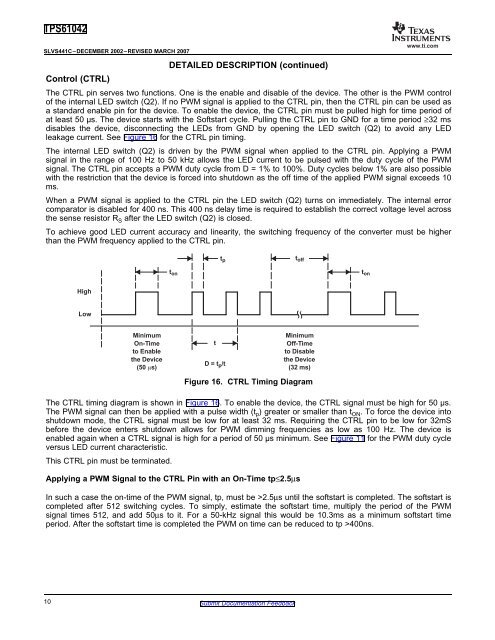
Figure 16. CTRL Timing Diagram<br />
The CTRL timing diagram is shown in Figure 16. To enable the device, the CTRL signal must be high for 50 µs.<br />
The PWM signal can then be applied with a pulse width (t p) greater or smaller than t ON. To force the device into<br />
shutdown mode, the CTRL signal must be low for at least 32 ms. Requiring the CTRL pin to be low for 32mS<br />
before the device enters shutdown allows for PWM dimming frequencies as low as 100 Hz. The device is<br />
enabled again when a CTRL signal is high for a period of 50 µs minimum. See Figure 11 for the PWM duty cycle<br />
versus <strong>LED</strong> current characteristic.<br />
This CTRL pin must be terminated.<br />
In such a case the on-time of the PWM signal, tp, must be >2.5μs until the softstart is completed. The softstart is<br />
completed after 512 switching cycles. To simply, estimate the softstart time, multiply the period of the PWM<br />
signal times 512, and add 50μs to it. For a 50-kHz signal this would be 10.3ms as a minimum softstart time<br />
period. After the softstart time is completed the PWM on time can be reduced to tp >400ns.<br />
10 Submit Documentation Feedback


