Constant Current LED Driver (Rev. C) - Educypedia
Constant Current LED Driver (Rev. C) - Educypedia
Constant Current LED Driver (Rev. C) - Educypedia
Create successful ePaper yourself
Turn your PDF publications into a flip-book with our unique Google optimized e-Paper software.
TPS61042<br />
SLVS441C–DECEMBER 2002–REVISED MARCH 2007<br />
Input Capacitor Selection<br />
Diode Selection<br />
Efficiency<br />
V <strong>LED</strong> I <strong>LED</strong><br />
V I I I<br />
www.ti.com<br />
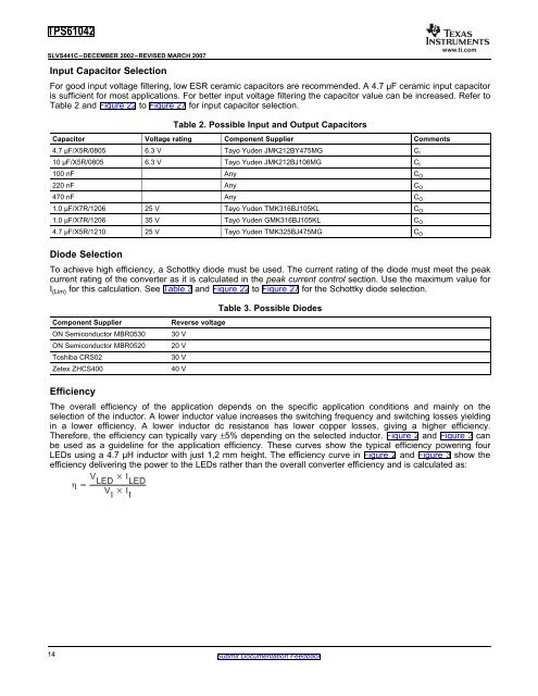
For good input voltage filtering, low ESR ceramic capacitors are recommended. A 4.7 µF ceramic input capacitor<br />
is sufficient for most applications. For better input voltage filtering the capacitor value can be increased. Refer to<br />
Table 2 and Figure 22 to Figure 27 for input capacitor selection.<br />
Table 2. Possible Input and Output Capacitors<br />
Capacitor Voltage rating Component Supplier Comments<br />
4.7 µF/X5R/0805 6.3 V Tayo Yuden JMK212BY475MG C I<br />
10 µF/X5R/0805 6.3 V Tayo Yuden JMK212BJ106MG C I<br />
100 nF Any C O<br />
220 nF Any C O<br />
470 nF Any C O<br />
1.0 µF/X7R/1206 25 V Tayo Yuden TMK316BJ105KL C O<br />
1.0 µF/X7R/1206 35 V Tayo Yuden GMK316BJ105KL C O<br />
4.7 µF/X5R/1210 25 V Tayo Yuden TMK325BJ475MG C O<br />
To achieve high efficiency, a Schottky diode must be used. The current rating of the diode must meet the peak<br />
current rating of the converter as it is calculated in the peak current control section. Use the maximum value for<br />
I (Lim) for this calculation. See Table 3 and Figure 22 to Figure 27 for the Schottky diode selection.<br />
Component Supplier <strong>Rev</strong>erse voltage<br />
ON Semiconductor MBR0530 30 V<br />
ON Semiconductor MBR0520 20 V<br />
Toshiba CRS02 30 V<br />
Zetex ZHCS400 40 V<br />
Table 3. Possible Diodes<br />
The overall efficiency of the application depends on the specific application conditions and mainly on the<br />
selection of the inductor. A lower inductor value increases the switching frequency and switching losses yielding<br />
in a lower efficiency. A lower inductor dc resistance has lower copper losses, giving a higher efficiency.<br />
Therefore, the efficiency can typically vary ±5% depending on the selected inductor. Figure 2 and Figure 3 can<br />
be used as a guideline for the application efficiency. These curves show the typical efficiency powering four<br />
<strong>LED</strong>s using a 4.7 µH inductor with just 1,2 mm height. The efficiency curve in Figure 2 and Figure 3 show the<br />
efficiency delivering the power to the <strong>LED</strong>s rather than the overall converter efficiency and is calculated as:<br />
14 Submit Documentation Feedback


