

Constant Current LED Driver (Rev. C) - Educypedia
Constant Current LED Driver (Rev. C) - Educypedia
Constant Current LED Driver (Rev. C) - Educypedia

You also want an ePaper? Increase the reach of your titles
YUMPU automatically turns print PDFs into web optimized ePapers that Google loves.
TPS61042<br />
SLVS441C–DECEMBER 2002–REVISED MARCH 2007<br />
APPLICATION INFORMATION<br />
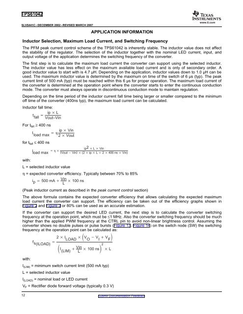
Inductor Selection, Maximum Load <strong>Current</strong>, and Switching Frequency<br />
Inductor fall time:<br />
ip L<br />
t <br />
fall Vout–Vin<br />
For tfall ≥ 400 ns<br />
ip Vin<br />
I <br />
load max 2Vout<br />
ip2 L Vin<br />
I <br />
load max (VoutVin) (2 ip L2 400 ns Vin)<br />
ip 500 mA Vin<br />
η = expected converter efficiency. Typically between 70% to 85%<br />
100 ns<br />
L<br />
www.ti.com<br />
The PFM peak current control scheme of the TPS61042 is inherently stable. The inductor value does not affect<br />
the stability of the regulator. The selection of the inductor together with the nominal <strong>LED</strong> current, input, and<br />
output voltage of the application determines the switching frequency of the converter.<br />
The first step is to calculate the maximum load current the converter can support using the selected inductor.<br />
The inductor value has less effect on the maximum available load current and is only of secondary order. A<br />
good inductor value to start with is 4.7 µH. Depending on the application, inductor values down to 1.0 µH can be<br />
used. The maximum inductor value is determined by the maximum on time of the switch of 6 µs (typ). The peak<br />
current limit of 500 mA (typ) must be reached within this 6 µs for proper operation. The maximum load current of<br />
the converter is determined at the operation point where the converter starts to enter the continuous conduction<br />
mode. The converter must always operate in discontinuous conduction mode to maintain regulation.<br />
Depending on the time period of the inductor current fall time being larger or smaller compared to the minimum<br />
off time of the converter (400ns typ), the maximum load current can be calculated.<br />
for t fall ≤ 400 ns<br />
with:<br />
L = selected inductor value<br />
(Peak inductor current as described in the peak current control section)<br />
The above formula contains the expected converter efficiency that allows calculating the expected maximum<br />
load current the converter can support. The efficiency can be taken out of the efficiency graphs shown in<br />
Figure 2 and Figure 3 or 80% can be used as an accurate estimation.<br />
fs(ILOAD) <br />
2 I V V V <br />
LOAD O I F<br />
I <br />
(LIM) Vin<br />
If the converter can support the desired <strong>LED</strong> current, the next step is to calculate the converter switching<br />
frequency at the operation point, which must be ≤1 MHz. Also the converter switching frequency should be much<br />
higher than the applied PWM frequency at the CTRL pin to avoid non-linear brightness control. Assuming the<br />
converter shows no double pulses or pulse bursts (Figure 13, Figure 14) on the switch node (SW) the switching<br />
frequency at the operation point can be calculated as:<br />
100 ns2 L<br />
L<br />
with:<br />
I (LIM) = minimum switch current limit (500 mA typ)<br />
L = selected inductor value<br />
I (LOAD) = nominal load or <strong>LED</strong> current<br />
V F = Rectifier diode forward voltage (typically 0.3 V)<br />
12 Submit Documentation Feedback


