Numerical Study of Passive and Active Flow Separation Control ...
Numerical Study of Passive and Active Flow Separation Control ...
Numerical Study of Passive and Active Flow Separation Control ...

You also want an ePaper? Increase the reach of your titles
YUMPU automatically turns print PDFs into web optimized ePapers that Google loves.
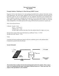
Fig. 8. Perspective view <strong>of</strong> the airfoil <strong>and</strong> mesh in ξ -ζ plane<br />
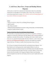
Fig. 9. Vortex generator <strong>and</strong> mesh on the upper surface <strong>of</strong> the airfoil <strong>and</strong> in ξ -ζ plane<br />
The flow parameters used by the numerical simulation are summarized in Table 2.<br />
The Reynolds number based on the freestream velocity <strong>and</strong> the chord length is 10 5 . The<br />
freestream Mach number is 0.2. The body-fitted mesh has 840 × 90 × 120 grid points.<br />
Based on the wall unit <strong>of</strong> fully developed turbulent boundary layer flow, the grid size on<br />
the upper surface <strong>of</strong> the airfoil downstream <strong>of</strong> the vortex generator is x 18<br />
+<br />
∆ ≈ , y 6<br />
+<br />
∆ ≈ ,<br />
<strong>and</strong> z 0.75<br />
+<br />
∆ ≈ . The time step size is<br />
∆ = .<br />
-4<br />
t 1.09×10 C/ U∞ 15