Operation Manual 354 Lighting System - Medical Equipment Pros
Operation Manual 354 Lighting System - Medical Equipment Pros
Operation Manual 354 Lighting System - Medical Equipment Pros

Create successful ePaper yourself
Turn your PDF publications into a flip-book with our unique Google optimized e-Paper software.
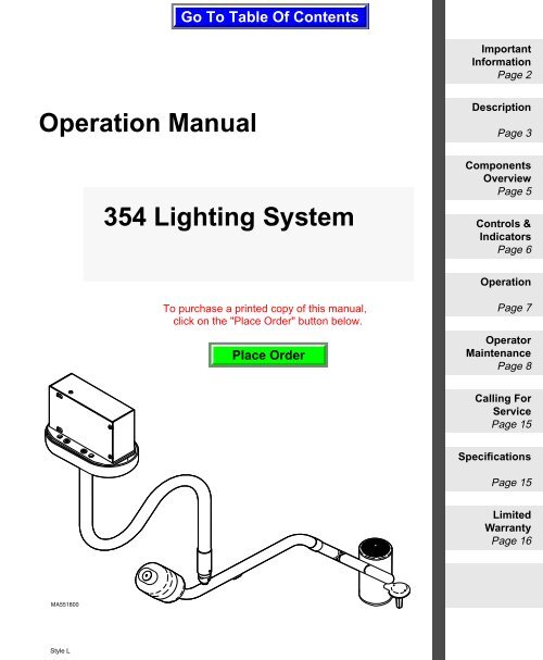
<strong>Operation</strong> <strong>Manual</strong><br />
<strong>354</strong> <strong>Lighting</strong> <strong>System</strong><br />
Important<br />
Information<br />
Page 2<br />
Description<br />
Page 3<br />
Components<br />
Overview<br />
Page 5<br />
Controls &<br />
Indicators<br />
Page 6<br />
<strong>Operation</strong><br />
Page 7<br />
Operator<br />
Maintenance<br />
Page 8<br />
Calling For<br />
Service<br />
Page 15<br />
Specifications<br />
Page 15<br />
Limited<br />
Warranty<br />
Page 16
Owner’s Product Identification<br />
(information that you will need to provide for servicing - key information is highlighted)<br />
Date of Purchase Serial Number<br />
Name of Owner / Facility / Department Model Number<br />
Name of Authorized Dealer Telephone # of Authorized Dealer<br />
Address of Authorized Dealer<br />
MODEL AND SERIAL<br />
NUMBER LOCATION
CONTENTS<br />
IMPORTANT INFORMATION .................................................................................................2<br />
Scope and Purpose of This <strong>Manual</strong>................................................................................2<br />
Intended Use of Product.................................................................................................2<br />
Safety Instructions ..........................................................................................................2<br />
Explanation of Safety Symbols and Notes......................................................................2<br />
Transportation and Storage Conditions ..........................................................................3<br />
DESCRIPTION........................................................................................................................3<br />
Introduction.....................................................................................................................3<br />
Features .........................................................................................................................4<br />
COMPONENTS OVERVIEW ..................................................................................................5<br />
CONTROLS & INDICATORS .................................................................................................6<br />
OPERATION ...........................................................................................................................7<br />
Electromagnetic Interference..........................................................................................7<br />
Operating Lighthead Assembly.......................................................................................7<br />
OPERATOR MAINTENANCE ................................................................................................8<br />
Preventive Maintenance Schedule .................................................................................8<br />
Troubleshooting Guide ...................................................................................................8<br />
Bulb Replacement Procedure.......................................................................................10<br />
Fuse Replacement Procedure......................................................................................12<br />
Ball Pivot Tension Adjustment Procedure.....................................................................13<br />
Cleaning and Disinfecting.............................................................................................14<br />
CALLING FOR SERVICE.....................................................................................................15<br />
SPECIFICATIONS ................................................................................................................15<br />
LIMITED WARRANTY..........................................................................................................16
Important<br />
Information<br />
2<br />
IMPORTANT INFORMATION<br />
Scope and Purpose of This <strong>Manual</strong><br />
This manual covers complete instructions for the operation of the <strong>354</strong> <strong>Lighting</strong><br />
<strong>System</strong> and is intended to be used by medical personnel responsible for operating<br />
the <strong>354</strong> <strong>Lighting</strong> <strong>System</strong> during medical procedures or performing operator<br />
level maintenance. The installation manual is a separate document.<br />
Intended Use of Product<br />
This product is intended for use in all medical environments where illumination<br />
is required for external examinations and procedures.<br />
Safety Instructions<br />
The primary concern of Midmark is that this equipment is operated and maintained<br />
with the safety of the patient and staff in mind. To assure safer and more<br />
reliable operation:<br />
• Read and understand this manual before attempting to install or operate the<br />
ceiling light system.<br />
• Assure that appropriate personnel are informed on the contents of this manual;<br />
this is the responsibility of the purchaser.<br />
• Assure that this manual is located near the ceiling light system.<br />
Explanation of Safety Symbols and Notes<br />
DANGER<br />
Indicates an imminently hazardous situation which, if not<br />
avoided, will result in death or serious injury. The DANGER<br />
symbol is limited to the most extreme situations.<br />
WARNING<br />
Indicates a potentially hazardous situation which, if not avoided,<br />
could result in death or serious injury.<br />
CAUTION<br />
Indicates a potentially hazardous situation which, if not avoided,<br />
may result in minor or moderate injury. It may also be used to alert<br />
against unsafe practices.
EQUIPMENT ALERT<br />
Indicates an imminently or potentially hazardous situation which, if<br />
not avoided, will or may result in serious, moderate, or minor<br />
equipment damage.<br />
NOTE<br />
Amplifies an operating procedure, practice, or condition.<br />
A<br />
Transportation and Storage Conditions<br />
• Ambient Temperature Range:..... -22°F to +140°F (-30°C to +60°C)<br />
• Relative Humidity........................ 10% to 90% (non-condensing)<br />
• Atmospheric Pressure ................ 0.5 bar to 1.06 bars (500hPa to 1060hPa)<br />
This product contains glass, so it should be transported and stored with care to<br />
limit vibration and shocks.<br />
DESCRIPTION<br />
Introduction<br />
Lighthead<br />
Indicates that the unit is rated:<br />
Type B, Applied Part.<br />
Indicates that the operator’s manual<br />
should be consulted for important<br />
information.<br />
Indicates the presence of a dangerous<br />
voltage / shock hazard.<br />
V<br />
Indicates a fuse rating specification<br />
Indicates a protective earth<br />
ground.<br />
Indicates that the product is fragile;<br />
do not handle roughly.<br />
Indicates the proper shipping orientation<br />
for the product.<br />
Indicates that the product must be<br />
kept dry.<br />
Indicates a hot surface.<br />
The <strong>354</strong> lighthead assembly is a compact spotlight. The spotlight design provides<br />
excellent control over the diameter of the lighted area. Through the movement<br />
of two levers, the user has complete control over the light beam diameter<br />
between 3 in. (7.6 cm) to 10 in. (25.4 cm) and over the brightness of the lighted<br />
area. The peak illumination is 4,000 fc (43,000 lux) at a distance of 36 in. (91.4<br />
cm). The plastic handle can be easily removed for sterilization or it accepts a<br />
Devon EZ Handle without requiring an awkward adapter. The arm assembly<br />
has been precisely designed, assembled, and balanced so that the lighthead<br />
Important<br />
Information<br />
Description<br />
3
Description<br />
4<br />
can be positioned with minimal force and no drifting will occur. In addition, multiple<br />
pivot points make the positioning of the lighthead easy and flexible.<br />
Features<br />
The Model <strong>354</strong> lighting system . . .<br />
• has a power supply with three input taps, allowing the voltage output to the<br />
light bulb to be adjusted according to the particular input voltage available at<br />
a facility. This prevents premature failure of the light bulb and lighthead components<br />
as well as unsatisfactory performance.<br />
• has a peak illumination of 4,000 fc (43,000 lux) at 36 in. (91.4 cm), but can<br />
be adjusted to a lower intensity (brightness) if desired.<br />
• provides a round beam of light which can be adjusted from a diameter of 3<br />
in. to 10 in. (7.6 to 25.4 cm) - based on a distance of 36 in. (91.4 cm) from<br />
surface being lit.<br />
• has two joint pivots with 580° of rotation, one pivot joint with 540° of rotation,<br />
and one pivot joint with 180° of rotation making positioning of the lighthead<br />
easy and flexible.<br />
• has an arm reach of 48 in. (122 cm) (from centerline of down tube to center<br />
of lighthead).<br />
• is precisely balanced so that the lighthead can be positioned with minimal<br />
force and no drifting will occur.<br />
• has a plastic handle which can be easily removed for sterilization or it<br />
accepts a Devon EZ Handle.
COMPONENTS OVERVIEW<br />
The illustration below shows the location of the light system’s major components<br />
and the chart below provides their descriptive name.<br />
DESCRIPTION OF COMPONENTS<br />
1. Down Tube Assembly 6. Lamp Tube Assembly<br />
2. Ceiling Plate 7. Lighthead Assembly<br />
3. Junction Box (includes trans- 8. Positioning Handle (sterilizable)<br />
former and fuse)<br />
4. Cross Tube Assembly 9. Ball Pivot Joint<br />
5. Ballast Assembly<br />
Description<br />
Components<br />
Overview<br />
5
Controls &<br />
Indicators<br />
6<br />
CONTROLS & INDICATORS<br />
The illustration below shows the location of the light system’s controls and indicators<br />
and the chart below describes their function; the on / standby control for<br />
the light system is located on the underside of the cross tube assembly and a<br />
replaceable fuse is located on the underside of the ceiling plate, under the ceiling<br />
cover (see fuse replacement procedure later in this manual).<br />
ON<br />
STANDBY<br />
ON / STANDBY<br />
CONTROL
Ref. Control Function<br />
1 on / standby switch (indicated<br />
by international<br />
symbol for on / standby:<br />
I /<br />
OPERATION<br />
Electromagnetic Interference<br />
This product is designed and built to minimize electromagnetic interference with<br />
other devices. However, if interference is noticed between another device and<br />
this product, remove the interfering device from the room or plug this product into<br />
an isolated circuit.<br />
Operating Lighthead Assembly<br />
turns the light system on or off.<br />
2 fuse holder can be removed and inspected to determine if<br />
the fuse has been blown, indicating a current<br />
surge or problem with the light.<br />
3 sterilizable positioning<br />
handle<br />
allows sterile personnel to move the lighthead<br />
without compromising the sterility of their<br />
hands.<br />
4 brightness control lever used to adjust the brightness of the light<br />
beam.<br />
5 beam size control lever used to adjust the size (diameter) of the light<br />
beam.<br />
EQUIPMENT ALERT<br />
Do not obstruct the airflow of the lighthead or damage to lighthead<br />
could result. If the <strong>354</strong> light system malfunctions, immediately<br />
turn the ON / STANDBY switch to STANDBY “ “.<br />
Turn the lighthead on by switching the ON / STANDBY switch (I / ) to ON “I”<br />
(See previous illustration). To adjust the position of the lighthead, grasp the<br />
sterile handle (3) and rotate the arm assemblies and lighthead as necessary to<br />
obtain correct illumination on the patient (See previous illustration for amount of<br />
rotation for an axis). To turn off the lighthead, switch the ON / STANDBY (I /<br />
) to STANDBY “ “.<br />
Controls &<br />
Indicators<br />
<strong>Operation</strong><br />
7
Operator<br />
Maintenance<br />
8<br />
OPERATOR MAINTENANCE<br />
Preventive Maintenance Schedule<br />
The following preventive maintenance schedule should be followed. If a problem<br />
is detected, refer to the troubleshooting guide in this manual.<br />
FREQUENCY ACTIVITY<br />
semiannually Inspect rotation of lighthead. Make sure the lighthead rotates<br />
freely, without noise, and has 180° of rotation at lamp tube connection.<br />
Make sure the lighthead stays positioned at any point<br />
(without drifting) with respect to the lamp tube.<br />
semiannually Inspect the rotation of the lamp tube, cross tube, and down tube.<br />
Make sure the arm assemblies rotate freely and without noise.<br />
Make sure the arm assemblies don’t drift at any point in their<br />
range of motion. The lamp tube should have 540° of rotation at<br />
cross tube connection. The cross tube should have 580° of rotation<br />
at down tube connection and should also have a vertical<br />
range of motion from -35° to +35°. The down tube should have<br />
580° of rotation at ceiling mount connection.<br />
semiannually Turn light ON “I”. Rotate lighthead, lamp tube, cross tube, and<br />
down tube while observing lighthead. The lighthead should not<br />
intermittently flicker or stop illuminating while joints are being rotated.<br />
semiannually Check for excessive joint rotation (more than 540° or 580° of rotation).<br />
The physical hard stops for an axis may be broken.<br />
semiannually Inspect inside of lighthead for indications of broken material or<br />
other signs of damage. If damage to any part of lighthead is<br />
evident, do not continue to use lighthead.<br />
semiannually Turn light ON “I”. Verify that fan is operating. If fan is not operating,<br />
do not continue to use lighthead. Operating lighthead without<br />
a fan in operation may cause lenses to melt.<br />
Troubleshooting Guide<br />
If there is a malfunction with the light system, use the troubleshooting guide to<br />
correct the problem. Refer to the illustrations in the Components Overview and<br />
Controls & Indicators sections of this manual as necessary.<br />
PROBLEM POSSIBLE CAUSE SOLUTION<br />
no light from lighthead lighthead is on STAND- turn ON / STANDBY switch<br />
BY “ “.<br />
to ON “I”
no light from lighthead,<br />
but ON / STANDBY switch<br />
is ON “I”<br />
no light from lighthead although<br />
the bulb and fuse<br />
were checked; lighthead<br />
flashes intermittently<br />
when lighthead or arms<br />
are moved<br />
down tube, lamp tube, or<br />
lighthead does not rotate<br />
freely or drifts when released<br />
in desired position<br />
cross tube rotates (at ball<br />
pivot joint) too stiffly or<br />
drifts when released in desired<br />
position<br />
bulb has burned out refer to bulb replacement<br />
procedure in this manual<br />
fuse in junction box is<br />
blown<br />
no power to the junction<br />
box<br />
transformer is malfunctioning<br />
circuit or wiring problem<br />
within arm assemblies,<br />
junction box, or other<br />
part of lighting system<br />
brakes need adjustment<br />
or improper installation of<br />
ceiling plate<br />
tension needs to be adjusted<br />
or cross tube<br />
counterbalance needs to<br />
be adjusted<br />
refer to the fuse replacement<br />
procedure in this manual<br />
call your building maintenance<br />
electrician to check<br />
for facility power to the junction<br />
box<br />
call an authorized service<br />
technician<br />
call an authorized service<br />
technician<br />
call an authorized service<br />
technician<br />
refer to tension adjustment<br />
procedure in this manual. If<br />
proper tension cannot be<br />
achieved, call an authorized<br />
service technician<br />
Operator<br />
Maintenance<br />
9
Operator<br />
Maintenance<br />
10<br />
Bulb Replacement Procedure<br />
CAUTION<br />
Turn the ON / STANDBY switch to STANDBY “ “ before replacing<br />
bulb. Otherwise, electrical shock or hand burns could result.<br />
Move the lighthead as far as possible from the exam / surgical site to prevent<br />
contaminants from falling onto the exam / surgical site. Do not try to remove<br />
the bulb until the unit is allowed to cool. Otherwise, burns to the hands and<br />
fingers could result.<br />
NOTE<br />
Screw (1) is a captive screw. Only loosen captive screw; do not try to remove<br />
it.<br />
The phillips head screw (1) is different from the other two screws on the top<br />
cap. Loosen this screw only to slide out the bulb carriage assembly (2); the<br />
two other screws secure the top cap to the fan mounting plate.<br />
1. If light is on, turn the ON / STANDBY switch to STANDBY “ “. Move lighthead<br />
away from exam / surgical site. Lower the lighthead to gain access for<br />
bulb removal.<br />
2. Using a phillips head screwdriver, loosen one screw (1) and then slide bulb<br />
carriage (2) out of outer housing (3).<br />
WARNING<br />
The maximum allowable bulb wattage which can be used in<br />
this light is 150 Watts. There is a risk of fire if the 150 Watt<br />
limit is exceeded. Use Midmark Part Number: 015-1212-00.<br />
NOTE<br />
Halogen bulbs are sensitive to body oils. Be sure not to touch the inside surface<br />
of the reflector or glass capsule of the bulb during relamping or cleaning.<br />
Body oils create a hot spot on the bulb and may cause the bulb to burn out<br />
prematurely. If these portions of the bulb/reflector are handled, wipe with a<br />
clean, soft, lint free cloth. Wipe with alcohol and pat dry.<br />
3. Remove the old bulb (4) by first pulling the bulb ejector lever (5) to the rear<br />
and then gently pulling upward on the bulb with the other hand.<br />
4. Push the bulb ejector lever (5) forward.
1<br />
2<br />
6<br />
5. Grasp the new bulb (4) and insert the bulb into the bulb socket (6). Push the<br />
bulb all the way down until the base of the bulb is firmly seated against the<br />
bulb socket.<br />
6. Slide bulb carriage assembly (2) into outer housing (3) and secure by tightening<br />
screw (1).<br />
5<br />
3<br />
MA457700<br />
4<br />
Operator<br />
Maintenance<br />
11
Operator<br />
Maintenance<br />
12<br />
Fuse Replacement Procedure<br />
1. Turn the ON / STANDBY switch to STANDBY “ “.<br />
2. Remove four screws (1) and lower ceiling cover (2) from ceiling plate (3).<br />
3. Simultaneously press in on fuse cap (4) with a slotted screwdriver and rotate<br />
it 1/4 turn in the counterclockwise direction; then pull fuse cap from fuse<br />
holder (5).<br />
4. Pull fuse (6) out of fuse cap (4).<br />
5. Inspect fuse (6) for any indication that it has been blown (opened); i.e. burnt<br />
look, discolored, fuse cord melted through, etc. Discard fuse.<br />
6. Obtain a new fuse (6) of the same voltage rating, amperage rating, and type.<br />
Refer to the Specifications section in this manual.<br />
7. Insert one end of the new fuse (6) into the fuse cap (4).<br />
8. Insert fuse cap (4) into fuse holder (5) and rotate it 1/4 turn in the clockwise<br />
direction to secure it.<br />
9. Position ceiling cover (2) on ceiling plate (3) and secure with four screws (1).
Ball Pivot Tension Adjustment Procedure<br />
1. Remove screw (1) and slide ball pivot sleeve (2) up out of way.<br />
ASSEMBLY /<br />
DISASSEMBLY<br />
POSITION<br />
MEDIUM TENSION<br />
POSITION<br />
LIGHT TENSION<br />
POSITION<br />
STIFF TENSION<br />
POSITION<br />
2. Rotate cross tube (3) until adjustment hole (4) appears in the adjustment<br />
window opening.<br />
NOTE<br />
There are three settings which the ball pivot cam (5) can be set for: light tension,<br />
medium tension, or stiff tension. These settings may be changed according<br />
to the operator’s preference.<br />
3. Insert a phillips screwdriver into adjustment hole (4). Then, using the screwdriver,<br />
rotate ball pivot cam (5) to the desired tension setting.<br />
4. Remove the screwdriver and move the cross tube (3) about the ball pivot<br />
joint in a circular motion and up and down motion to ensure the setting is the<br />
one desired. Move the cross tube (3) to a horizontal position and release it.<br />
The cross tube should not drift in any direction. If it does, a higher tension<br />
setting is required or the cross tube counterbalance needs adjusted (see<br />
counterbalance adjustment in the Installation or Service and Parts <strong>Manual</strong>).<br />
Repeat steps 3 and 4 until the desired tension adjustment is achieved with<br />
no drifting of the cross tube.<br />
5. Slide ball pivot sleeve (2) down into position and secure with screw (1).<br />
Operator<br />
Maintenance<br />
13
Operator<br />
Maintenance<br />
14<br />
Cleaning and Disinfecting<br />
EQUIPMENT ALERT<br />
When cleaning or disinfecting the light, remove power from the<br />
light, allow optical unit to cool. Clean EXTERNAL SURFACES<br />
ONLY (arm assemblies and lighthead). Prevent fluids from leaking into interior<br />
or onto electrical contacts. DO NOT ATTEMPT to clean or disinfect interior;<br />
instead call an authorized dealer or service technician.<br />
EQUIPMENT ALERT<br />
Use only quaternary disinfectants to disinfect light. Staining, pitting,<br />
discoloration, or softening could occur if phenolic, iodophor,<br />
or glutaraldehyde-based disinfectant is used on plastic surfaces of the lighthead.<br />
Also, use of alcohol or aerosol spray cleaner / disinfectant containing<br />
substantial amounts of alcohol in the formula can damage the lens.<br />
External Cleaning Procedures<br />
For general cleaning, use a mild detergent and water solution. Wring excess<br />
solution from sponge or cloth before wiping.<br />
According to your facility’s procedure:<br />
1. Clean lens with an antistatic acrylic cleaning solution using a soft, clean<br />
cloth. Do not use alcohol or abrasive compounds on lens.<br />
2. Wipe external surface of arm assemblies and lighthead with a mild detergent<br />
and water solution.<br />
3. Rinse all external surfaces with a soft cloth and clear water, wringing excess<br />
from cloth before wiping.<br />
4. Wipe all external surfaces dry.<br />
External Disinfecting Procedures<br />
According to your facility’s procedure:<br />
1. Use only quaternary disinfectants to disinfect light. Staining, pitting, discoloration,<br />
or softening could occur if phenolic, iodophor, or glutaraldehydebased<br />
disinfectant is used on plastic surfaces of the lighthead. Also, use of<br />
alcohol or aerosol spray cleaner / disinfectant containing substantial<br />
amounts of alcohol in the formula can damage the lens.<br />
2. Wring excess solution from cloth.<br />
3. Using soft cloth, wipe all external surfaces of arm assemblies and lighthead.
4. Do not rinse or dry external surfaces. Allow disinfectant solution to air dry.<br />
Handle Sterilization<br />
• Use only steam sterilization on the handle.<br />
• Follow steam sterilization instructions of sterilizer manufacturer.<br />
CALLING FOR SERVICE<br />
If you are having a problem or have a question, refer to the inside front cover of<br />
this manual and call your dealer. Make sure that you have the information that<br />
is highlighted on the inside front cover of this manual available. If you can’t resolve<br />
your question or problem with your dealer, call the following number:<br />
SPECIFICATIONS<br />
1-800-Midmark (1-800-643-6275) or 937-526-3662<br />
8:00 a.m until 5:00 p.m. (Eastern Standard Time in U.S.)<br />
Monday through Friday, except for standard U.S. holidays.<br />
Model <strong>354</strong> Ceiling Light<br />
Beam diameter @ 36 in.: .............. Variable from 3 to 10 in. (7.6 cm to 25.4 cm)<br />
(91.4 cm)<br />
Bulb: ............................................... 21.0 VAC, 150 W halogen bulb<br />
Color temperature:........................ 4,200K<br />
Focal length:.................................. 36 in. (91.4 cm)<br />
Illumination @ 36 in. (91.4 cm): ... 4000 fc (43,000 lux)<br />
Electrical requirement: ................. 120 VAC, 60 HZ,<br />
1.5 amps, single phase<br />
Reach of arm assemblies:............ 49.5 in. (126 cm) maximum from centerline<br />
of down tube to center of lighthead.<br />
Rotation of lamp tube: .................. 180° rotation at lamp tube connection<br />
Rotation of lamp tube: .................. 540° rotation at cross tube connection<br />
Rotation of cross tube:................. 580° rotation at down tube connection<br />
Vertical range of cross tube:........ -35° to +35° vertical movement<br />
Rotation of down tube: ................. 580° rotation at ceiling plate connection<br />
Weight of 8 ft. (2.44 m) single<br />
light assembly: .............................. 59 lbs (26.8 kg)<br />
Weight of 9 ft. (2.74 m) single<br />
light assembly: .............................. 60 lbs (27.2 kg)<br />
Weight of 8 ft. (2.44 m) dual<br />
light assembly: .............................. 105 lbs (47.6 kg)<br />
Weight of 9 ft. (2.74 m) dual<br />
light assembly: .............................. 107 lbs (48.5 kg)<br />
Operator<br />
Maintenance<br />
Calling For<br />
Service<br />
Specifications<br />
15
Limited<br />
Warranty<br />
16<br />
Certifications: ................................ classified by Under<br />
writers Laboratories Inc. with respect to<br />
........................................................electric shock, fire, and mechanical haz<br />
ards only inaccordance with UL2601-1 and<br />
CAN/CSA C22.2, No.601.1.<br />
........................................................ISO-9001 Certified<br />
Classifications:..............................Class 1, Type B applied part, Ordinary<br />
<strong>Equipment</strong>, Continuous <strong>Operation</strong><br />
Fuse Rating:...................................1.6 amp, 250 VAC, 5mm x 20mm, Type T,<br />
low breaking capacity, IEC 127-2/3<br />
<strong>Equipment</strong> not suitable for use in the presence of a flammable anesthetic<br />
mixture with air, oxygen, or nitrous oxide.<br />
LIMITED WARRANTY<br />
MEDICAL EQUIPMENT<br />
UL60601-1,IEC60601-1,<br />
CAN/CSA C22 2 No 601 1<br />
SCOPE OF WARRANTY<br />
Midmark Corporation (“Midmark”) warrants to the original purchaser its new Alternate<br />
Care products and components (except for components not warranted under<br />
“Exclusions”) manufactured by Midmark to be free from defects in material and<br />
workmanship under normal use and service. Midmark’s obligation under this warranty<br />
is limited to the repair or replacement, at Midmark’s option, of the parts or the<br />
products the defects of which are reported to Midmark within the applicable warranty<br />
period and which, upon examination by Midmark, prove to be defective.<br />
APPLICABLE WARRANTY PERIOD<br />
The applicable warranty period, measured from the date of delivery to the original<br />
user, shall be one (1) year for all warranted products and components.<br />
EXCLUSIONS<br />
This warranty does not cover and Midmark shall not be liable for the following: (1)<br />
repairs and replacements because of misuse, abuse, negligence, alteration, accident,<br />
freight damage, or tampering; (2) products which are not installed, used, and<br />
properly cleaned as required in the Midmark “Installation” and or “Installation / <strong>Operation</strong><br />
<strong>Manual</strong> for this applicable product. (3) products considered to be of a consumable<br />
nature; (4) accessories or parts not manufactured by Midmark; (5) charges by<br />
anyone for adjustments, repairs, replacement parts, installation, or other work performed<br />
upon or in connection with such products which is not expressly authorized<br />
in writing in advance by Midmark.<br />
EXCLUSIVE REMEDY<br />
Midmark’s only obligation under this warranty is the repair or replacement of defective<br />
parts. Midmark shall not be liable for any direct, special, indirect, incidental,<br />
exemplary, or consequential damages or delay, including, but not limited to, damages<br />
for loss of profits or loss of use.
NO AUTHORIZATION<br />
No person or firm is authorized to create for Midmark any other obligation or liability<br />
in connection with the products.<br />
THIS WARRANTY IS MIDMARK’S ONLY WARRANTY AND IS IN LIEU OF ALL<br />
OTHER WARRANTIES, EXPRESS OR IMPLIED. MIDMARK MAKES NO<br />
IMPLIED WARRANTIES OF ANY KIND INCLUDING ANY WARRANTIES OF<br />
MERCHANTABILITY OR FITNESS FOR ANY PARTICULAR PURPOSE. THIS<br />
WARRANTY IS LIMITED TO THE REPAIR OR REPLACEMENT OF DEFECTIVE<br />
PARTS.<br />
SF-1487 REV. A1<br />
Limited<br />
Warranty<br />
17
Midmark Corporation, Versailles, Ohio 45380 U.S.A.<br />
© Midmark Corporation - 1999 937-526-3662 FAX: 937-526-5542<br />
003-1071-00 Rev. C (5-06)