Micropaq User Manual Model 406 and 408 - Medical Equipment Pros
Micropaq User Manual Model 406 and 408 - Medical Equipment Pros
Micropaq User Manual Model 406 and 408 - Medical Equipment Pros

You also want an ePaper? Increase the reach of your titles
YUMPU automatically turns print PDFs into web optimized ePapers that Google loves.
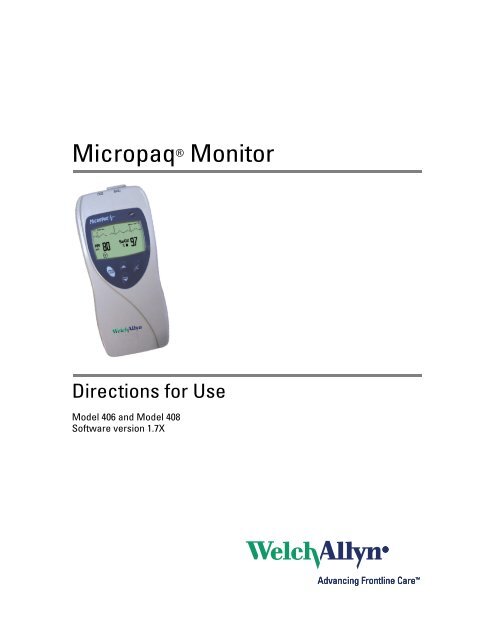
<strong>Micropaq</strong> ® Monitor<br />
Directions for Use<br />
<strong>Model</strong> <strong>406</strong> <strong>and</strong> <strong>Model</strong> <strong>408</strong><br />
Software version 1.7X
ii Welch Allyn <strong>Micropaq</strong> Monitor<br />
© 2008 Welch Allyn. All rights are reserved. No one is permitted to reproduce or duplicate, in any form, this manual or any<br />
part thereof without permission from Welch Allyn.<br />
Welch Allyn assumes no responsibility for injury or for any illegal or improper use of the product that may result from failure<br />
to use this product in accordance with the instructions, cautions, warnings, or indications for use published in this manual.<br />
Welch Allyn, Acuity, <strong>Micropaq</strong>, <strong>and</strong> FlexNet are registered trademarks of Welch Allyn.<br />
Nellcor is a registered trademark of Nellcor Puritan Bennett.<br />
Masimo <strong>and</strong> SET are registered trademarks of Masimo Corporation.<br />
Software in this product is copyright by Welch Allyn or its vendors. All rights are reserved. The software is protected by<br />
United States of America copyright laws <strong>and</strong> international treaty provisions applicable worldwide. Under such laws, the<br />
licensee is entitled to use the copy of the software incorporated within this instrument as intended in the operation of the<br />
product in which it is embedded. The software may not be copied, decompiled, reverse-engineered, disassembled or<br />
otherwise reduced to human-perceivable form. This is not a sale of the software or any copy of the software; all right, title<br />
<strong>and</strong> ownership of the software remain with Welch Allyn or its vendors.<br />
For information about any Welch Allyn product, please call Welch Allyn Technical Support:<br />
USA + 1 315 685 4560<br />
800 535 6663<br />
REF 810-2691-XX (CD)<br />
REF 810-2738-XX (Printed, English only)<br />
<strong>Manual</strong> Part Number 810-2702-01 Ver A, 2008/06<br />
www.welchallyn.com<br />
Australia + 61 2 9638 3000<br />
800 074 793<br />
Canada 800 561 8797 China + 86 216 327 9631<br />
European Call<br />
Center<br />
+ 35 3 46 906 7790 France + 33 1 60 09 33 66<br />
Germany + 49 7477 92 71 86 Japan + 81 3 3219 0071<br />
Latin America + 1 305 669 9003 Netherl<strong>and</strong>s + 31 15 750 5000<br />
Singapore + 65 6419 8100 South Africa + 27 11 777 7555<br />
United Kingdom + 44 20 7365 6780 Sweden + 46 8 58 53 65 51<br />
Welch Allyn Protocol, Inc.<br />
8500 SW Creekside Place<br />
Beaverton, OR 97008-7107 USA<br />
Welch Allyn Ltd<br />
Navan Business Park<br />
Dublin Road, Navan<br />
County Meath, Republic of Irel<strong>and</strong>
Contents<br />
1 - General information . . . . . . . . . . . . . . . . . . . . . . . . . . . . . . . . . . . . . . 1<br />
Intended use. . . . . . . . . . . . . . . . . . . . . . . . . . . . . . . . . . . . . . . . . . . . . . . . . . . . . 1<br />
General warnings <strong>and</strong> cautions. . . . . . . . . . . . . . . . . . . . . . . . . . . . . . . . . . . . . . . 4<br />
Introducing the monitor . . . . . . . . . . . . . . . . . . . . . . . . . . . . . . . . . . . . . . . . . . . . 7<br />
Underst<strong>and</strong>ing the monitor <strong>and</strong> the FlexNet Network . . . . . . . . . . . . . . . . . . . . . 8<br />
Monitor features . . . . . . . . . . . . . . . . . . . . . . . . . . . . . . . . . . . . . . . . . . . . . . . . . . 9<br />
Accessories . . . . . . . . . . . . . . . . . . . . . . . . . . . . . . . . . . . . . . . . . . . . . . . . . . . . 16<br />
Operating settings . . . . . . . . . . . . . . . . . . . . . . . . . . . . . . . . . . . . . . . . . . . . . . . 16<br />
Demonstration mode . . . . . . . . . . . . . . . . . . . . . . . . . . . . . . . . . . . . . . . . . . . . . 17<br />
2 - Monitoring . . . . . . . . . . . . . . . . . . . . . . . . . . . . . . . . . . . . . . . . . . . . . 19<br />
Connect a new patient . . . . . . . . . . . . . . . . . . . . . . . . . . . . . . . . . . . . . . . . . . . . 19<br />
Monitor a patient out of range of Acuity. . . . . . . . . . . . . . . . . . . . . . . . . . . . . . . 29<br />
Stop monitoring a patient . . . . . . . . . . . . . . . . . . . . . . . . . . . . . . . . . . . . . . . . . . 30<br />
Reconnect a recently monitored patient. . . . . . . . . . . . . . . . . . . . . . . . . . . . . . . 31<br />
Reassign a monitored patient to a new room in the same unit . . . . . . . . . . . . . 32<br />
Transfer a monitored patient to a new room in a different unit. . . . . . . . . . . . . . 33<br />
Reassign the monitor to a new patient. . . . . . . . . . . . . . . . . . . . . . . . . . . . . . . . 34<br />
3 - Alarms & alerts . . . . . . . . . . . . . . . . . . . . . . . . . . . . . . . . . . . . . . . . . 35<br />
About alarms <strong>and</strong> alerts . . . . . . . . . . . . . . . . . . . . . . . . . . . . . . . . . . . . . . . . . . . 35<br />
Alarm holdoffs . . . . . . . . . . . . . . . . . . . . . . . . . . . . . . . . . . . . . . . . . . . . . . . . . . 35<br />
Respond to a patient alarm at monitor . . . . . . . . . . . . . . . . . . . . . . . . . . . . . . . . 36<br />
Customize patient alarm limits at the monitor . . . . . . . . . . . . . . . . . . . . . . . . . . 37<br />
Respond to an equipment alert at the monitor. . . . . . . . . . . . . . . . . . . . . . . . . . 38<br />
Alert messages <strong>and</strong> display information. . . . . . . . . . . . . . . . . . . . . . . . . . . . . . . 40<br />
4 - Monitor patient at Acuity . . . . . . . . . . . . . . . . . . . . . . . . . . . . . . . . . 41<br />
5 - Maintenance . . . . . . . . . . . . . . . . . . . . . . . . . . . . . . . . . . . . . . . . . . . 43<br />
Change the battery . . . . . . . . . . . . . . . . . . . . . . . . . . . . . . . . . . . . . . . . . . . . . . . 43<br />
Recharge a battery . . . . . . . . . . . . . . . . . . . . . . . . . . . . . . . . . . . . . . . . . . . . . . . 43<br />
Inspect <strong>and</strong> clean the monitor <strong>and</strong> accessories . . . . . . . . . . . . . . . . . . . . . . . . . 45<br />
Recycling monitor components . . . . . . . . . . . . . . . . . . . . . . . . . . . . . . . . . . . . . 46<br />
Change the network name . . . . . . . . . . . . . . . . . . . . . . . . . . . . . . . . . . . . . . . . . 47<br />
6 - Reference . . . . . . . . . . . . . . . . . . . . . . . . . . . . . . . . . . . . . . . . . . . . . . 49<br />
Operating settings . . . . . . . . . . . . . . . . . . . . . . . . . . . . . . . . . . . . . . . . . . . . . . . 49<br />
iii
iv Contents Welch Allyn <strong>Micropaq</strong> Monitor<br />
Specifications . . . . . . . . . . . . . . . . . . . . . . . . . . . . . . . . . . . . . . . . . . . . . . . . . . . 50<br />
7 - Compliance . . . . . . . . . . . . . . . . . . . . . . . . . . . . . . . . . . . . . . . . . . . . 61<br />
Index . . . . . . . . . . . . . . . . . . . . . . . . . . . . . . . . . . . . . . . . . . . . . . . . . . . . 73
1<br />
Intended use<br />
General information<br />
The <strong>Micropaq</strong> ® monitor is intended to be used by clinicians for single or multiparameter<br />
vital signs monitoring of ambulatory <strong>and</strong> nonambulatory pediatric <strong>and</strong> adult patients in<br />
health care facilities. The monitor is able to withst<strong>and</strong> light rain exposure over short<br />
periods of time (uniform distribution of approximately 1 mm of water per minute for 10<br />
minutes or less).<br />
The <strong>Micropaq</strong> monitor is intended to operate with an Acuity ® Central Monitoring System<br />
through wireless communication over the Welch Allyn ® FlexNet ® network. FlexNet<br />
connects multiple devices to the Acuity Central Monitoring System through hardwired<br />
Ethernet networks <strong>and</strong> Wireless Local Area Networks (WLANs). If the <strong>Micropaq</strong> monitor<br />
is moved out of range or loses communication with the FlexNet network, it continues to<br />
monitor the patient, display patient data, <strong>and</strong> generate local patient alarms or alert<br />
messages.<br />
The ECG channel is intended primarily for five-lead ECG monitoring, although<br />
three-lead ECG monitoring is supported.<br />
The Pulse Oximetry channel is intended for continuous noninvasive monitoring of<br />
functional oxygen saturation of arterial hemoglobin (SpO2 ) <strong>and</strong> pulse rate<br />
(measured by an SpO2 sensor).<br />
The most likely locations for patients monitored by this device are step-down units,<br />
telemetry departments, general medical/surgical floors, emergency departments, <strong>and</strong> inhospital<br />
transport.<br />
This guide was written for clinicians. Although this guide may describe some monitoring<br />
techniques, Welch Allyn expects that the operator is a trained clinician who knows how to<br />
take <strong>and</strong> interpret a patient’s vital signs.<br />
Federal USA law restricts sale of the device identified in this manual to, or on the order of,<br />
a licensed medical practitioner.<br />
1
2 Chapter 1 General information Welch Allyn <strong>Micropaq</strong> Monitor<br />
Symbols<br />
Warning Warning statements in this manual identify conditions or practices that could result in personal<br />
injury.<br />
Caution Caution statements in this manual identify conditions or practices that could result in damage to the<br />
equipment or other property.<br />
Caution On the product, means “Consult the accompanying documentation.”<br />
The following symbols appear on the monitor or accessories.<br />
Symbol Definition Symbol Definition<br />
Li++<br />
Direct current Enclosure Protection Drip proof: Classification<br />
IPX1<br />
IPX1 per EN60529: 1991<br />
Alternating current (battery charger) Fuse<br />
The CE Mark <strong>and</strong> Notified Body Registration<br />
Number signify the device has met all essential<br />
requirements of European <strong>Medical</strong> Device<br />
Directive 93/42/EEC<br />
Restrictions for use of wireless device in<br />
Europe. European Communities Class 2 radio<br />
equipment<br />
This device has been tested <strong>and</strong> certified by<br />
the Canadian St<strong>and</strong>ards Association<br />
International to comply with applicable U.S.<br />
<strong>and</strong> Canadian medical safety st<strong>and</strong>ards.<br />
Signifies the device has met all essential<br />
requirements of European <strong>Medical</strong> Device<br />
Directive 93/42/EEC for a Class 1 product<br />
(battery charger)<br />
Protective earth ground (battery charger) Separate batteries from other disposables for<br />
recycling<br />
Lithium Ion battery For indoor use only (battery charger)<br />
Caution: Refer to Directions For Use <strong>and</strong><br />
accompanying documentation<br />
C US<br />
Keep away from rain<br />
See the accompanying manual Recycle the monitor <strong>and</strong> battery<br />
separately from other waste. Refer to<br />
www.welchallyn.com/weee for collection<br />
point <strong>and</strong> additional information.<br />
Alarm(s) off Patient connections are Type CF, isolated for<br />
direct cardiac application, <strong>and</strong> protected<br />
against defibrillation<br />
This way up Stacking limit (by number)<br />
Li++<br />
Humidity limit Altitude limit<br />
Fragile IATA/ICAO Hazard Class 9 Package<br />
(International Air Transport Association/<br />
9<br />
International Civil Aviation Organization)<br />
Temperature limits Single use only
Directions for Use Chapter 1 General information 3<br />
Symbol Definition Symbol Definition<br />
Non-ionizing electromagnetic radiation. This<br />
device contains an approved RLAN module<br />
frequency 2402 to 2480 MHz<br />
Non-ionizing electromagnetic radiation. This<br />
device contains an approved RLAN module<br />
frequency 5150 to 5825 MHz<br />
The monitor is connected to Acuity The monitor is not connected to Acuity<br />
(Flashing) The monitor is searching for a<br />
connection to Acuity<br />
Select Key <strong>and</strong> Silence Patient Alarm/<br />
<strong>Equipment</strong> Alert Key- Selects the choice<br />
highlighted on the menu. During patient alarms,<br />
silences the tone at the monitor <strong>and</strong> at Acuity (if<br />
connected) for 90 seconds. During equipment<br />
alerts, silences or acknowledges (dismisses) the<br />
alert.<br />
Snapshot Key - When connected to Acuity,<br />
pressing this key sends Acuity a snapshot print<br />
to the Acuity central station printer. A total of<br />
21 seconds of patient numeric <strong>and</strong> waveform<br />
data (14 seconds of history, 7 seconds after the<br />
key is pressed) will be sent to the printer. See<br />
”Snapshot key” on page 10 for more<br />
information.<br />
FCC ID:<br />
PGUWA11AO7<br />
IC:<br />
4168a-WA11A07<br />
Monitor Front Panel Keys<br />
This device complies with FCC <strong>and</strong><br />
Industry Canada requirements for<br />
international radiators (802.11 wireless)<br />
Scroll Up Key <strong>and</strong> Reset Alarm Tone Key-<br />
Scrolls up menus on the display. During patient<br />
alarms, resets the tone at the monitor <strong>and</strong> at<br />
Acuity (if connected).<br />
Scroll Down Key <strong>and</strong> Main Menu Key- Pressing<br />
this key scrolls down menus on the display, or<br />
causes the Main Menu to appear if no menu is<br />
displayed.
4 Chapter 1 General information Welch Allyn <strong>Micropaq</strong> Monitor<br />
Battery charger labels <strong>and</strong> LEDs<br />
General warnings <strong>and</strong> cautions<br />
Eight-bay battery charger<br />
(008-0651-XX)<br />
Green LED on continuously Battery is fully charged.<br />
Green LED flashing<br />
kj<br />
Battery is charging.<br />
Green LED flashing very slowly Battery detected <strong>and</strong> waiting to be charged.<br />
Yellow LED on continuously Something is wrong with the battery or the<br />
charger. (See ”Battery Status <strong>and</strong> Possible<br />
Response” on page 44.)<br />
Familiarize yourself with all warnings <strong>and</strong> cautions before using the monitor.<br />
WARNING When considering a treatment protocol that involves wireless<br />
communication of patient data, be sure to recognize some limitations inherent<br />
in wireless communications. When the monitor is not connected to the<br />
network:<br />
• There are no patient alarms or alerts at the Acuity Central Station.<br />
Acuity does not perform arrhythmia <strong>and</strong> ST analysis on the patient data<br />
<strong>and</strong> does not generate related alarms.<br />
Patient data is not saved.<br />
WARNING Do not try to monitor neonatal patients with the monitor. The<br />
monitor is intended for adult or pediatric patients. It is not intended for use with<br />
pediatric patients (or infants) weighing less than 22 lbs (10 kg).<br />
WARNING Always check the patient mode at Acuity when monitoring a new<br />
patient. The patient mode determines default alarm limits <strong>and</strong> internal algorithm<br />
settings.<br />
WARNING The monitor may not meet its performance specifications if stored<br />
or used outside the specified temperature <strong>and</strong> humidity ranges.<br />
WARNING Do not connect more than one patient to a monitor. Do not connect<br />
more than one monitor to a patient.<br />
WARNING During defibrillation, keep the discharge paddles away from ECG<br />
<strong>and</strong> other electrodes, as well as other conductive parts in contact with the<br />
patient.<br />
WARNING Do not operate this product in the presence of flammable<br />
anesthetics or other flammable substances in combination with air, oxygenenriched<br />
environments, or nitrous oxide; explosion can result.<br />
WARNING Do not use the monitor in a Magnetic Resonance Imaging (MRI)<br />
suite or a hyperbaric chamber. Such use can cause fire or explosion resulting in<br />
patient injury <strong>and</strong> monitor damage.
Directions for Use Chapter 1 General information 5<br />
WARNING Electronic equipment that emits strong electromagnetic or radio<br />
frequency signals can cause electrical interference with monitor operation. This<br />
interference may distort the ECG signal, thereby preventing accurate rhythm<br />
analysis. Avoid operating this device near equipment of this type.<br />
WARNING Exposure to Radio Frequency (RF) radiation. To comply with Federal<br />
Communications Commission (FCC) RF exposure requirements, this device<br />
shall be used in accordance with the operating conditions <strong>and</strong> instructions<br />
provided in this manual, including the section ”Install the carrying pouch” on<br />
page 28.<br />
WARNING Pacemaker signals can differ from one pacemaker to the next. The<br />
Association for Advancement of <strong>Medical</strong> Instrumentation (AAMI) cautions that<br />
“in some devices, rate meters may continue to count the pacemaker rate during<br />
occurrences of cardiac arrest or some arrhythmias. Do not rely entirely upon rate<br />
meter alarms. All pacemaker patients should be kept under close or constant<br />
observation.” See ”ECG specifications” on page 51 for disclosure of the<br />
pacemaker pulse rejection capability of this instrument.<br />
WARNING This wireless medical device was tested <strong>and</strong>, when used with a<br />
metal-free accessory between the monitor <strong>and</strong> the patient, complies with FCC<br />
RF Exposure (SAR) guidelines. The use of accessories containing metal may not<br />
ensure compliance with FCC RF exposure guidelines. Specific Absorption Rate<br />
(SAR) is a measurement of radio frequency energy. The FCC permits a<br />
maximum SAR value of 1.6 mW/g. The highest SAR value for this patient<br />
monitor, when worn by a patient in accordance with the directions for use, is<br />
0.560 mW/g.<br />
WARNING Military radars are allocated as primary users in the b<strong>and</strong>widths<br />
between 5.25 - 5.35 GHz <strong>and</strong> 5.47 to 5.725 GHz. In the event a radar signature<br />
is detected, the Access Point moves to a new channel, which can temporarily<br />
interrupt patient monitoring. If the device is operated near a military radar, the<br />
radar could cause damage to the device."<br />
WARNING Changes or modifications not expressly approved by Welch Allyn<br />
could void the purchaser’s authority to operate the equipment. This product<br />
does not contain any user serviceable components. Any unauthorized product<br />
changes or modifications will invalidate Welch Allyn’s warranty <strong>and</strong> all applicable<br />
regulatory certifications <strong>and</strong> approvals.<br />
WARNING For patients with a pacemaker, position the monitor to maintain a<br />
minimum 6-inch distance between the monitor <strong>and</strong> pacemaker. Immediately<br />
turn the monitor off <strong>and</strong> provide appropriate patient care if you have any reason<br />
to suspect that the monitor is interfering with the pacemaker. The Health<br />
Industry Manufacturers Association recommends this minimum 6-inch distance<br />
between a h<strong>and</strong>-held wireless radio <strong>and</strong> a pacemaker, which is consistent with<br />
the independent research by, <strong>and</strong> recommendations of, Wireless Technology<br />
Research.<br />
WARNING Make frequent electrical <strong>and</strong> visual checks on cables, sensors, <strong>and</strong><br />
electrode wires. All cables, sensors, <strong>and</strong> electrode wires must be inspected <strong>and</strong><br />
properly maintained <strong>and</strong> in proper working order to allow the equipment to<br />
function properly <strong>and</strong> protect patient safety.<br />
WARNING Avoid electrosurgery burns at monitoring sites by ensuring proper<br />
connection of the electrosurgery return circuit so that the return paths cannot be<br />
made through monitoring electrodes <strong>and</strong> probes.<br />
WARNING Use of ECG <strong>and</strong> SpO 2 cables not specified by Welch Allyn may<br />
negate defibrillator protection <strong>and</strong> risk patient injury.
6 Chapter 1 General information Welch Allyn <strong>Micropaq</strong> Monitor<br />
WARNING Use of Masimo LNOP ® sensors/cables will not provide protection<br />
in accordance with IEC defibrillation st<strong>and</strong>ards when used with this device.<br />
WARNING To ensure patient safety, the conductive parts of the ECG<br />
electrodes (including associated connectors) <strong>and</strong> other patient-applied parts<br />
should not contact other conductive parts, including earth ground, at any time.<br />
WARNING Motion artifact can affect the accuracy of patient vital sign<br />
measurements. Minimize patient motion whenever possible.<br />
WARNING Use only accessories supplied by Welch Allyn or recommended in<br />
the Welch Allyn Products <strong>and</strong> Accessories booklet (810-0409-XX). The monitor<br />
will only meet the listed specifications when using accessories listed by Welch<br />
Allyn. Use accessories according to your facility’s st<strong>and</strong>ards <strong>and</strong> the<br />
manufacturer’s recommendations. Always refer to the manufacturer’s Directions<br />
for Use.<br />
WARNING As with all medical equipment, carefully route the patient cabling to<br />
reduce the possibility of patient entanglement or strangulation. Use the supplied<br />
garment clips to secure the cable properly.<br />
WARNING When positioning the monitor pouch on the patient, make sure the<br />
straps do not entangle the patient’s neck or cause choking. Make sure the straps<br />
do not restrict the movement of the patient’s limbs or create a hazard when<br />
walking or moving.<br />
WARNING If a product has been dropped or severely abused, send it to a<br />
qualified service person to confirm proper operation.<br />
WARNING Do not use the pulse oximeter as a replacement or substitute for<br />
ECG-based arrhythmia analysis.<br />
Caution Do not autoclave the monitor. Autoclave accessories only if the<br />
manufacturer’s instructions clearly approve it. Many accessories can be severely<br />
damaged by autoclaving.<br />
It is possible for the monitor to detect a problem that prevents the monitor from operating<br />
properly. If this occurs, the monitor displays an error message <strong>and</strong> error number. Report<br />
such errors to Welch Allyn. The monitor should be serviced only by a Welch Allyn service<br />
technician while under warranty. Contact Welch Allyn for information about post-warranty<br />
period service.
Directions for Use Chapter 1 General information 7<br />
Introducing the monitor<br />
<strong>Model</strong> <strong>406</strong><br />
<strong>Model</strong> <strong>408</strong><br />
The monitor is a patient-worn vital signs monitor for use by adult or pediatric ambulatory<br />
patients.<br />
One or two ECG channels displayed<br />
Up to 2 ECG leads displayed at the monitor:<br />
I, II, III, V, aVR, aVL, or aVF with 5-lead cable<br />
Up to 7 ECG leads displayed at Acuity:<br />
I, II, III, V, aVR , aVL , or aVF with 5-lead cable<br />
One ECG lead displayed at the monitor <strong>and</strong><br />
at Acuity: Fixed lead II with 3-lead cable, or<br />
5-lead cable with only RA, LA <strong>and</strong> LL<br />
electrodes attached.<br />
Pulse oximetry (SpO2) monitoring (<strong>Model</strong><br />
<strong>408</strong> only)<br />
Two-way wireless communication within<br />
Welch Allyn’s FlexNet network<br />
LCD for display of ECG waveforms, SpO2 <strong>and</strong> heart rate/pulse rate data, <strong>and</strong><br />
messages from Acuity<br />
St<strong>and</strong>alone operation with patient alarms<br />
when out of range of the network<br />
Patient alarm limits that can be set at the<br />
monitor or at Acuity<br />
Configurable formats for single- or dual-waveform ECG display<br />
Internal antenna<br />
Snapshot key<br />
Lightweight (less than two pounds with battery)<br />
Rugged <strong>and</strong> tolerant of brief water exposure<br />
Rechargeable battery<br />
Sleep mode to extend battery life<br />
Your model may be shipped with an attached identification number on the front of the<br />
monitor.<br />
ECG monitoring<br />
ECG monitoring <strong>and</strong> either one of two pulse oximetry (SpO 2 ) monitoring options:<br />
SpO 2 with Masimo ® SET ® technology, indicated by:<br />
SpO 2 with NELLCOR ® OxiMax ® technology, indicated by:
8 Chapter 1 General information Welch Allyn <strong>Micropaq</strong> Monitor<br />
Underst<strong>and</strong>ing the monitor <strong>and</strong> the FlexNet Network<br />
The monitor is intended to operate with an Acuity ® Central Station as part of Welch Allyn’s<br />
FlexNet network. FlexNet allows multiple devices to communicate through hardwired<br />
Ethernet networks <strong>and</strong> Wireless Local Area Networks (WLANs). The Acuity Central<br />
Station provides the primary display <strong>and</strong> entry of patient data for a patient connected to<br />
the monitor.<br />
To Other Acuity<br />
Central Stations<br />
Acuity Central Station<br />
80 97<br />
HR SpO2<br />
FlexNet Network<br />
Access Points<br />
<strong>Micropaq</strong> monitors<br />
To Other<br />
Access<br />
Points<br />
Each patient-worn monitor supports two-way communication with an Acuity Central<br />
Station through an access point in the FlexNet network. The access point is a digital radio<br />
transceiver that connects to the FlexNet network. During monitoring, the monitor sends<br />
the patient data to Acuity. Acuity <strong>and</strong> the monitor continuously analyze the data. Acuity<br />
provides appropriate alarm or alert messages at the Central Station <strong>and</strong> other network<br />
devices such as a hallway message panel <strong>and</strong> the monitor itself. Acuity also stores the<br />
patient data for viewing or report printing.<br />
If the monitor is moved out of range or loses communication with the FlexNet network<br />
<strong>and</strong> Acuity, it continues to monitor the patient <strong>and</strong> display patient data. While not<br />
communicating with Acuity, the monitor continues to generate local patient alarms or<br />
alert messages. Patient data is not stored <strong>and</strong> Acuity does not perform waveform analysis<br />
or generate arrhythmia messages while the monitor is not communicating with Acuity.<br />
When the monitor is returned to within range of the FlexNet network, it automatically<br />
reconnects to Acuity.<br />
80 97<br />
HR SpO2<br />
80 97<br />
HR SpO2<br />
80 97<br />
HR SpO2
Directions for Use Chapter 1 General information 9<br />
Monitor features<br />
Controls <strong>and</strong> connectors<br />
Snapshot key<br />
Battery pack latch<br />
Battery<br />
SpO2 Connector<br />
ECG Connector<br />
Visual Alarm Indicator<br />
Liquid Crystal Display<br />
Select Key <strong>and</strong><br />
Silence Patient Alarm/<br />
<strong>Equipment</strong> Alert Key<br />
Scroll Up Key <strong>and</strong> Reset Patient Alarm Tone Key<br />
Scroll Down Key <strong>and</strong> Main Menu Key<br />
SpO 2<br />
connector clip<br />
(model <strong>408</strong>) or<br />
cover (model<br />
<strong>406</strong>)<br />
Back
10 Chapter 1 General information Welch Allyn <strong>Micropaq</strong> Monitor<br />
Visual alarm indicator<br />
Audible alarm indicator<br />
Snapshot key<br />
Green Flashes slowly during normal operation.<br />
Red Flashes during patient alarm, remains on continuously when alarms are<br />
silenced or suspended.<br />
Yellow Flashes during an equipment alert or while not connected to the network.<br />
Remains on continuously if the operator suspends an alert at Acuity for 90<br />
seconds or acknowledges (dismisses) a low battery alert from the monitor<br />
or Acuity.<br />
Note The flashing green LED indicates that the monitor is connected to the network<br />
but not necessarily connected to a patient. If the monitor is actively monitoring a<br />
patient, the green LED indicates no alarms or alerts are detected.<br />
Beeps to indicate a patient alarm, <strong>and</strong> beeps faster for life-threatening arrhythmia<br />
alarms (see ”Patient alarm <strong>and</strong> equipment alert specifications” on page 56).<br />
Beeps to indicate when the equipment needs attention. This beep tone is slower than<br />
patient alarm tones (see ”Patient alarm <strong>and</strong> equipment alert specifications” on<br />
page 56).<br />
Volume can be configured as high, low, or off (configured at Acuity).<br />
Volume can be configured differently for network connection or st<strong>and</strong>-alone operation<br />
(configured at Acuity).<br />
When connected to Acuity, pressing this key sends a snapshot of the patient’s<br />
numeric <strong>and</strong> waveform data to the Acuity Central Monitoring System. Depending on<br />
how Acuity is configured, this will cause Acuity to print a 21-second snapshot (14<br />
seconds of history, 7 seconds of data after the button is pressed) to the Acuity central<br />
station printer.<br />
Note Snapshot is the default selection of the monitor. However, the connected<br />
monitor will inherit the configuration previously defined by Acuity. For example,<br />
if Acuity has defined the Snapshot key to respond with a Nurse Call function <strong>and</strong><br />
a new monitor is introduced to the system, the Snapshot key definition will<br />
remain as Nurse Call.<br />
For more information about using the Acuity Central Monitoring System, refer to<br />
Acuity Directions For Use (810-1605-XX)<br />
Scroll Up key <strong>and</strong> Reset Patient Alarm Tone key<br />
Scrolls up menus on the display.<br />
Resets a silenced patient alarm tone.
Directions for Use Chapter 1 General information 11<br />
Battery<br />
Scroll Down key <strong>and</strong> Main Menu key<br />
Scrolls down menus on the display.<br />
Displays the Main Menu.<br />
Select key <strong>and</strong> Silence Patient Alarm/<strong>Equipment</strong> Alert key<br />
Selects the choice highlighted on the menu.<br />
During patient alarms, silences the tone at the monitor <strong>and</strong> Acuity (if connected) for<br />
90 seconds. During equipment alerts, silences or acknowledges (dismisses) the alert<br />
at the monitor <strong>and</strong> Acuity.<br />
Insert the battery to turn on power. Remove the battery to turn off power. (While the<br />
battery is removed, the monitor does not perform patient monitoring.)<br />
Note If you do not use END TELE to disconnect from the network as described<br />
above, the Acuity Central Station generates a DROPOUT equipment alert at<br />
Acuity.<br />
If you want to monitor this same patient at a later time, you will need to reselect<br />
the patient name from the monitor or confirm the patient ID at Acuity.<br />
Recharge the battery while it is removed from the monitor. (See ”Recharge a battery”<br />
on page 43.)<br />
To order a new battery, see ”Battery Status <strong>and</strong> Possible Response” on page 44.
12 Chapter 1 General information Welch Allyn <strong>Micropaq</strong> Monitor<br />
Display<br />
Display sleep mode<br />
Although the Acuity Central Station is the primary location for viewing patient data, the<br />
monitor provides information to support patient care.<br />
Waveform scale is<br />
selectable<br />
ECG lead is selectable<br />
HR indicates the heart<br />
rate is from ECG.<br />
PR (pulse rate) is<br />
displayed if SpO 2 is active<br />
<strong>and</strong> ECG is not (pulse rate<br />
is derived from SpO 2 ).<br />
If the monitor detects<br />
a vital sign outside<br />
the measurable range,<br />
it displays:<br />
- - - (below the range)<br />
+ + + (above the range).<br />
Indicates the monitor<br />
is connected to<br />
Acuity.<br />
This symbol indicates the monitor is not<br />
communicating with Acuity:<br />
Flashing indicates the monitor is associated<br />
with an access point, but not communicating<br />
with Acuity.<br />
Continuous on indicates the monitor is not<br />
communicating with an access point or Acuity.<br />
Dashed lines indicate the<br />
monitor detects a pacemaker<br />
signal (display of pacer<br />
detection can be enabled or<br />
disabled at Acuity)<br />
Indicates one or<br />
more patient alarms<br />
are disabled (off).<br />
Patient name as entered at<br />
Acuity.<br />
If the patient name has not<br />
been entered, the monitor<br />
displays the last four digits of<br />
the monitor serial number, such<br />
as:<br />
ID:6472<br />
Symbol is displayed at the<br />
monitor whenever the<br />
Snapshot key is pressed.<br />
ECG waveform is displayed<br />
when active.<br />
SpO 2 numeric data is a<br />
percentage value.<br />
Low battery icon flashes to<br />
indicate monitor will shut off in<br />
30 minutes or less.<br />
SpO 2 pulse amplitude indicator<br />
(not proportional to pulse<br />
volume)<br />
In order to extend battery life, the display becomes blank after two minutes if no keys are<br />
pressed. The display becomes active again if an alarm or alert occurs, a key is pressed,<br />
the initial Acuity connection occurs, a cable is inserted, or an electrode is attached.<br />
The display will not become blank if a patient alarm is occurring, an Acuity message is<br />
displayed, or the monitor is in Demo mode or Service mode.
Directions for Use Chapter 1 General information 13<br />
Main Menu<br />
When you first press , the Main Menu appears:<br />
Press to move through the menu.<br />
Press to select or change the highlighted choice.<br />
EXIT Exit the Main Menu (the menu disappears).<br />
ACUITY... Access the Acuity Menu with network options. The Acuity Menu<br />
is only accessible while connected to Acuity.<br />
EXIT Exit all menus <strong>and</strong> return to the monitoring<br />
screen.<br />
END TELE Discontinue monitoring a patient.<br />
NEW ROOM Reassign a patient to a new room in the same<br />
unit.<br />
TRANSFER Transfer a patient to a new room in a new unit.<br />
NEW PATIENT Assign the monitor to a new patient.<br />
PATIENT INFO Display patient information such as ID, name,<br />
unit <strong>and</strong> room.<br />
Whenever the monitor is connected to Acuity <strong>and</strong> you select<br />
ACUITY... from the Main Menu, the monitor displays the message<br />
ACUITY CONTACTED to confirm that Acuity has been contacted.<br />
The monitor continues to display this message until Acuity<br />
responds, or you press to acknowledge the message <strong>and</strong> clear<br />
the screen. If the monitor detects an alarm or alert, it clears the<br />
screen to display the appropriate alarm or alert message. The<br />
length of time required for Acuity to respond to your selection at<br />
the monitor can vary widely depending on the amount of network<br />
traffic <strong>and</strong> other conditions.<br />
ECG LEAD... Access a menu to change the ECG 1 or ECG 2 lead selection (I, II,<br />
III, aVR , aVL , aVF , or V). Available vectors depend on the connected<br />
electrodes.
14 Chapter 1 General information Welch Allyn <strong>Micropaq</strong> Monitor<br />
ECG SCALE... Change the scale of the ECG waveform. If two waveforms are<br />
displayed, both have the same scale.<br />
1 WAVEFORM There are four possible ECG waveform display selections:<br />
1 WAVEFORM the default selection<br />
2 WAVEFORMS<br />
5 SECONDS<br />
FULL SCREEN<br />
Pressing changes to the next selection. This change does not<br />
take effect until after you exit the Main Menu. See ”Display” on<br />
page 12 for descriptions.<br />
LIMITS... Enter the Alarm Limits Menu (”Customize patient alarm limits at<br />
the monitor” on page 37) <strong>and</strong> change alarm limits.<br />
SYSTEM<br />
INFORMATION<br />
Display information about the network connection <strong>and</strong> SpO 2<br />
module.<br />
SERVICE MENU Enter Service Mode for a demonstration mode (Demo, see<br />
”Demonstration mode” on page 17) or service functions for<br />
technicians. Service Mode is not available if any cables are<br />
plugged in.<br />
Note To restrict access to the Main Menu, a Menu Lock option can be configured for<br />
the monitor at the Acuity Central Station. When the Menu Lock is enabled, the<br />
operator must press <strong>and</strong> hold down <strong>and</strong> for two seconds to gain access<br />
to the Main Menu. The Menu Lock is disabled if the monitor loses<br />
communication with Acuity.
Directions for Use Chapter 1 General information 15<br />
Waveform options<br />
There are four ECG waveform options as shown:<br />
1 Waveform<br />
The single ECG 1 (lead II)<br />
waveform is displayed.<br />
5 Seconds<br />
ECG 1 (lead II) cascades from<br />
one line to the other.<br />
To change the waveform selection during operation:<br />
1. Press to display the Main Menu.<br />
2 Waveforms<br />
ECG 1 (lead II) <strong>and</strong> ECG 2<br />
(lead V) are both displayed.<br />
Full Screen<br />
The single ECG 1 (lead II) waveform is<br />
allowed to occupy most of the screen.<br />
2. Press as needed to highlight the current waveform selection. Then press as<br />
needed to select the desired display.
16 Chapter 1 General information Welch Allyn <strong>Micropaq</strong> Monitor<br />
Messages from Acuity<br />
Accessories<br />
The monitor displays messages sent from Acuity as needed, including patient alarms <strong>and</strong><br />
equipment alerts. When Acuity messages are displayed, they temporarily override<br />
information displayed on the lower half of the monitor screen.<br />
Operating settings<br />
Default settings<br />
Battery charger (8-battery) <strong>Micropaq</strong> Directions For Use<br />
Battery ECG electrodes<br />
3-lead ECG cable (optional) 5-lead ECG cable<br />
ECG extension cable (optional) Carrying pouch<br />
SpO2 sensors (Masimo or Nellcor) SpO2 cable (Masimo or Nellcor)<br />
WARNING Use only accessories supplied by Welch Allyn or recommended in<br />
the Welch Allyn Products <strong>and</strong> Accessories booklet (810-0409-XX). The monitor<br />
will only meet the listed specifications when using accessories listed by Welch<br />
Allyn. Use accessories according to your facility’s st<strong>and</strong>ards <strong>and</strong> the<br />
manufacturer’s recommendations. Always refer to the manufacturer’s Directions<br />
for Use.<br />
The following monitor operating settings can be set at the monitor or at the Acuity Central<br />
Station:<br />
Patient alarm limit settings (ECG <strong>and</strong> SpO 2 ).<br />
ECG lead <strong>and</strong> scale selection<br />
ECG display format<br />
Many other monitor operating settings (such as patient mode <strong>and</strong> alarms volume) can<br />
only be set at the Acuity Central Station. See ”Operating settings” on page 49 for a list of<br />
all settings <strong>and</strong> where they are set.<br />
When the monitor connects to Acuity for a new patient, the Acuity Central Station<br />
downloads the appropriate default settings stored at Acuity. While the monitor is<br />
connected to Acuity, settings can be changed either at the monitor or at the Acuity Central<br />
Station.<br />
If the monitor is temporarily disconnected from Acuity <strong>and</strong> the operator changes settings<br />
at the monitor, those settings are transmitted to <strong>and</strong> stored at Acuity when the monitor<br />
reconnects.
Directions for Use Chapter 1 General information 17<br />
Demonstration mode<br />
You can practice using the monitor with the Demo mode of operation, including<br />
connection to Acuity.<br />
The Demo mode cannot be activated while you are monitoring a patient or if any cables<br />
have been plugged into the monitor. During the Demo mode, the monitor <strong>and</strong> Acuity<br />
display the message SIMULATION.<br />
To practice with the monitor in Demo mode:<br />
1. Disconnect all patient cables connected to the monitor.<br />
2. Remove the battery (if installed).<br />
3. Insert the battery <strong>and</strong> watch for the Power-Up screen.<br />
Power-Up Screen<br />
4. After the Power-Up screen disappears, press to display the Main Menu.<br />
Main Menu
18 Chapter 1 General information Welch Allyn <strong>Micropaq</strong> Monitor<br />
5. Press to highlight SERVICE MENU, then press to display the Service Menu.<br />
6. Press to highlight DEMO MENU, then press to display the Demo Menu.<br />
7. Press to highlight DEMO 1 or DEMO 2, then press to start.<br />
Demo Mode Display Values <strong>and</strong> Alarm Limits<br />
Display Demo 1 Demo 2a Alarm Limits (On)<br />
ECG Waveform Normal sinus rhythm,<br />
normal ST<br />
ECG Heart Rate<br />
SpO 2 Pulse Rate<br />
Service Menu<br />
Demonstration Mode<br />
a. Demo 2 will cause patient alarms.<br />
Normal sinus rhythm,<br />
normal ST<br />
SIMULATION indicates the<br />
Demo mode is active.<br />
A simulated waveform <strong>and</strong><br />
numerics are displayed.<br />
(not applicable)<br />
80 125 Lower 50<br />
Upper 120<br />
SpO 2 Saturation% 97 88 Lower 90<br />
Upper 100<br />
8. While in Demo mode you can practice changing settings such as ECG lead selection<br />
<strong>and</strong> alarm limit adjustment. (These changes only affect the Demo mode <strong>and</strong> are<br />
erased when you exit the Demo mode.)<br />
9. To change to the other Demo selection, press to display the menu, then scroll<br />
down to highlight TOGGLE DEMO MODE <strong>and</strong> press .<br />
10. To exit the Demo mode, either insert a patient cable or remove <strong>and</strong> insert the battery.<br />
The monitor restarts <strong>and</strong> enters the normal monitoring mode.
2<br />
Monitoring<br />
Connect a new patient<br />
Connect to the network<br />
1. Insert a battery into the monitor to turn it on. After a few seconds the monitor Power-<br />
Up Screen is replaced by an initial monitoring screen.<br />
The monitor is<br />
searching for a<br />
network<br />
connection.<br />
Example of Initial Monitor Screen<br />
If any patient cables are<br />
connected, there will be<br />
some patient data displayed.<br />
The format depends on the<br />
monitor default settings.<br />
2. After the network connection is established, the monitor may prompt you to select an<br />
Acuity Unit (if your facility has more than one Acuity unit):<br />
Possible Acuity Unit<br />
selections.<br />
Press to view more.<br />
Example of Acuity Unit Selection<br />
19
20 Chapter 2 Monitoring Welch Allyn <strong>Micropaq</strong> Monitor<br />
3. Press or to highlight the desired Acuity unit, then press .<br />
When you press or to highlight the desired Acuity unit <strong>and</strong> then press ,<br />
your selection will begin to flash between normal <strong>and</strong> reverse video to confirm that<br />
the monitor is communicating your selection to Acuity. You cannot scroll to another<br />
selection during this time. The selection continues to flash until Acuity responds back<br />
to the monitor. Then the monitor displays the next appropriate screen (such as a list of<br />
possible patients). The length of time required for Acuity to respond to your selection<br />
at the monitor can vary widely depending on the amount of network traffic <strong>and</strong> other<br />
conditions.<br />
Be sure to select an Acuity unit. Even though the monitor is<br />
connected to the network (as indicated by the green LED <strong>and</strong><br />
network connection symbol), the Acuity Central Station may not<br />
display any indication of this monitor until after you have selected an<br />
Acuity unit.<br />
4. The monitor displays a list of possible patients.<br />
If your patient has been pre-admitted to the selected Acuity unit, they will be included<br />
in the list.<br />
Possible<br />
patients to<br />
select.<br />
Select Patient at Central<br />
428-02-2392, Hopkins, Bill J<br />
520-29-0319, Phillips, Mary L<br />
532-94-8372, Smith, Frank R<br />
5. Scroll through the patient list to look for your patient’s name.<br />
▼<br />
Example of Patient List<br />
SELECT<br />
PATIENT<br />
Network Connection<br />
Symbol<br />
If your patient is not in the list, highlight Select Patient at Central <strong>and</strong> press .<br />
The patient name will need to be entered later at the Acuity Central Station.<br />
WARNING If you do not select the patient name at the monitor at this time, do<br />
not adjust any alarm limits until after the patient name <strong>and</strong> ID are confirmed at<br />
Acuity. When the patient name <strong>and</strong> ID are confirmed at Acuity, Acuity<br />
downloads the default settings <strong>and</strong> patient alarm limits for that Acuity unit to the<br />
monitor, thereby overriding any previous settings <strong>and</strong> alarm limits.<br />
Note At power-up, the monitor retains the most recent patient mode. The patient<br />
mode can only be changed at Acuity. If the patient is being monitored when the<br />
patient mode is changed, there is a brief interruption in the display <strong>and</strong> recording<br />
of ECG <strong>and</strong> SpO 2 patient data.
Directions for Use Chapter 2 Monitoring 21<br />
If your patient is in the list, highlight the name <strong>and</strong> press . Within a few<br />
seconds the monitor displays a list of unassigned rooms.<br />
Possible<br />
rooms to<br />
select.<br />
If you want to assign the patient to a room, highlight the room <strong>and</strong> press .<br />
If you do not want to assign a room at this time, highlight Select Room at<br />
Central <strong>and</strong> press . The patient room will need to be entered later at the<br />
monitor (see “Reassign a monitored patient to a new room in the same unit” on<br />
page 32) or at Acuity (see “Monitor patient at Acuity” on page 41).<br />
6. If you need to customize alarm limits for your patient, see “Customize patient alarm<br />
limits at the monitor” on page 37.<br />
Perform ECG monitoring<br />
Select Room at Central<br />
1104A<br />
1104B<br />
1105A<br />
▼<br />
Example of Room List<br />
SELECT<br />
ROOM<br />
WARNING Motion artifact can cause incorrect heart rate readings. Minimize<br />
patient motion whenever possible.<br />
WARNING If a disconnected lead is in too close proximity to other electrical<br />
devices, it may cause false heart rate readings.<br />
WARNING The monitor does not provide internal arrhythmia analysis.<br />
Therefore, arrhythmias may cause the monitor to display inaccurate heart rates.<br />
WARNING The monitor will show + + + for HR numerics between 301 <strong>and</strong><br />
350 beats per minute. Above 350 beats per minute, it may display incorrectly<br />
low heart rates, due to intermittent picking of R-waves.<br />
WARNING Do not use the monitor in a Magnetic Resonance Imaging (MRI)<br />
suite or a hyperbaric chamber. Such use can cause fire or explosion resulting in<br />
patient injury <strong>and</strong> monitor damage.<br />
WARNING Pacemaker signals can differ from one pacemaker to the next. The<br />
Association for Advancement of <strong>Medical</strong> Instrumentation (AAMI) cautions that<br />
“in some devices, rate meters may continue to count the pacemaker rate during<br />
occurrences of cardiac arrest or some arrhythmias. Do not rely entirely upon rate<br />
meter alarms. All pacemaker patients should be kept under close or constant<br />
observation.” See “ECG specifications” on page 51 for disclosure of the<br />
pacemaker pulse rejection capability of this instrument.
22 Chapter 2 Monitoring Welch Allyn <strong>Micropaq</strong> Monitor<br />
WARNING For patients with a pacemaker, position the monitor to maintain a<br />
minimum 6-inch distance between the monitor <strong>and</strong> pacemaker. Immediately<br />
turn the monitor off <strong>and</strong> provide appropriate patient care if you have any reason<br />
to suspect that the monitor is interfering with the pacemaker. The Health<br />
Industry Manufacturers Association recommends this minimum 6-inch distance<br />
between a h<strong>and</strong>-held wireless radio <strong>and</strong> a pacemaker, which is consistent with<br />
the independent research by, <strong>and</strong> recommendations of, Wireless Technology<br />
Research.<br />
WARNING High-intensity radio frequency (RF) energy from external sources,<br />
such as an improperly connected electrosurgical unit, can induce heat into<br />
electrodes <strong>and</strong> cables which can cause burns on the patient. Reading errors <strong>and</strong><br />
damage to equipment may also result. This hazard can be reduced by (1)<br />
avoiding the use of small ECG electrodes, (2) selecting ECG electrode<br />
attachment points remote from the surgical site <strong>and</strong> from the electrosurgical<br />
return electrode, (3) using electrosurgical return electrodes with the largest<br />
practical contact area, <strong>and</strong> (4) assuring proper application of the electrosurgical<br />
return electrode to the patient.<br />
WARNING Verify patient mode at Acuity. Incorrect patient mode may result in<br />
inaccurate heart rates <strong>and</strong> inappropriate alarm settings.<br />
WARNING To help prevent injury, use the provided garment clips to route the<br />
ECG cables away from the patient’s head.<br />
WARNING Use of ECG cables with loose or faulty detachable lead wires may<br />
cause erratic behavior of the ECG waveform due to intermittent ECG lead wire<br />
connections.<br />
WARNING To ensure patient safety, the conductive parts of the ECG<br />
electrodes (including associated connectors) <strong>and</strong> other patient-applied parts<br />
should not contact other conductive parts, including earth ground, at any time.<br />
Caution To protect the monitor from damage during defibrillation, for accurate<br />
ECG information, <strong>and</strong> for protection against noise <strong>and</strong> other interference, use<br />
only ECG electrodes <strong>and</strong> cables specified or supplied by Welch Allyn (these<br />
cables have the required current-limiting resistors). Follow recommended<br />
application procedures.<br />
Caution Do not use an ECG cable longer than 10 feet (3 meters). If the nominal<br />
length of the ECG cable, including extensions, exceeds this length, the monitor<br />
is not guaranteed to meet published electromagnetic compatibility (EMC)<br />
performance specifications.<br />
Even though the monitor contains fully isolated patient-connected circuitry, it has not<br />
been specially designed for direct application on a patient’s heart.<br />
Use only with accessories provided or recommended in the Welch Allyn Products <strong>and</strong><br />
Accessories booklet (810-0409-XX).<br />
Severe artifact <strong>and</strong> interference (such as defibrillation interference) can cause the<br />
waveform to move off the display for a few seconds before it is restored.
Directions for Use Chapter 2 Monitoring 23<br />
Perform 5-Lead ECG monitoring<br />
1. Inspect the ECG cable <strong>and</strong> replace it if it shows any signs of wear, breakage, or<br />
fraying. Plug the cable into the monitor.<br />
2. Select electrode sites on the patient.<br />
Choose flat areas; avoid fatty or bony areas <strong>and</strong> major muscles.<br />
3. Shave or clip hair from electrode sites, thoroughly clean skin, <strong>and</strong> lightly rub dry.<br />
You may use soap <strong>and</strong> water, isopropyl alcohol or special skin preparation pads. To<br />
avoid allergic reactions to electrodes, refer to the electrode manufacturer’s directions.<br />
4. If you are using pre-gelled electrodes, make sure the electrode date is not expired <strong>and</strong><br />
the gel is intact <strong>and</strong> not dried out. For best results, use only silver/silver chloride<br />
electrodes.<br />
If you are using ungelled electrodes, apply a 1/4- to 1/2-inch mound of gel over the<br />
electrode contact area.<br />
For best product performance <strong>and</strong> measurement accuracy, do not use stainless steel<br />
needle electrodes, squeeze bulb electrodes, or electrodes with dissimilar metals. Due<br />
to polarization, such electrodes can generate offsets beyond the monitor’s<br />
capabilities. Do not use electrodes from more than one manufacturer on the same<br />
patient.<br />
5. Attach lead wires to the electrodes before applying them to the patient. Apply the<br />
electrodes to the patient in the proper locations.<br />
Right Arm<br />
Right Leg<br />
Flashing circle indicates the<br />
lead is not connected.<br />
Left Arm<br />
Left Leg<br />
If the monitor detects that some lead wires are not properly connected, the monitor<br />
displays a chest diagram <strong>and</strong> indicates which leads are disconnected.<br />
The locations of the circles displayed on the monitor for each lead are fixed, <strong>and</strong> are<br />
not affected by the exact placement of the electrodes on the patient. For example,<br />
the C lead can be placed on the patient in any one of the V1-V6 locations desired, but<br />
will only be displayed on the monitor in the location shown above.<br />
6. After leads are properly connected, confirm that the monitor displays the ECG<br />
waveform, heart rate, <strong>and</strong> other patient data.<br />
To change the ECG lead selection, press to display the Main Menu. Then press<br />
Scroll Down to highlight ECG LEAD . . . , then highlight ECG 1 or ECG 2 <strong>and</strong> press<br />
to change the lead.
24 Chapter 2 Monitoring Welch Allyn <strong>Micropaq</strong> Monitor<br />
3-Lead ECG application with the 5-Lead ECG cable<br />
Note Be aware that there are some inherent limitations with this application,<br />
especially when compared to 5-lead ECG monitoring. These limitations include<br />
the restriction to only one displayed lead, ECG lead II. Because only one<br />
displayed lead is available (ECG lead II), factors such as a poor electrode<br />
connection at RA, LA, or LL can significantly affect performance. To overcome<br />
these limitations, the 5-lead ECG monitoring is preferred.<br />
The monitor’s 3-lead ECG monitoring is only available for use with Acuity<br />
software versions 6.1 or later.<br />
You can perform 3-lead ECG monitoring in a similar manner as 5-lead ECG monitoring. You<br />
may use the 5-lead ECG cable with detachable electrode lead wires, <strong>and</strong> connect only the<br />
lead wires <strong>and</strong> electrodes for RA, LA, <strong>and</strong> LL. Refer to the Welch Allyn Product <strong>and</strong><br />
Accessories booklet (810-0409-XX) for part numbers.<br />
Follow these steps:<br />
1. Perform Step 1 through Step 4 on page 23 as described for 5-lead ECG monitoring.<br />
2. Before attaching electrodes to the patient, attach only lead wires for RA, LA, <strong>and</strong> LL to<br />
the 5-lead ECG trunk cable <strong>and</strong> to the electrodes. Make sure that lead wires for C <strong>and</strong><br />
RL are DETACHED from the 5-lead ECG trunk cable.<br />
3. Apply the electrodes for RA, LA, <strong>and</strong> LL to the patient in the proper locations.<br />
The monitor displays the chest diagram with two circles blinking confirming that the C<br />
<strong>and</strong> RL electrodes are not connected.<br />
4. Observe the monitor <strong>and</strong> visually confirm that within about 30 seconds, the two<br />
circles disappear <strong>and</strong> the monitor displays the ECG waveform, heart rate, <strong>and</strong> other<br />
patient data.<br />
Be aware that if you connect the C or RL lead wires to the 5-lead ECG trunk cable <strong>and</strong><br />
apply the C or RL electrodes to the patient, the monitor defaults to 5-lead ECG<br />
monitoring <strong>and</strong> does not enable 3-lead ECG monitoring. To enable 3-lead ECG<br />
monitoring, you must disconnect the ECG cable from the monitor for a few seconds,<br />
<strong>and</strong> then begin this procedure again.
Directions for Use Chapter 2 Monitoring 25<br />
Be aware that only ECG lead II is available for display with the monitor’s 3-lead ECG<br />
monitoring. No other ECG lead selections are available.<br />
WARNING Do not try to perform this 3-lead ECG monitoring with any 5-lead<br />
ECG cable that does not have detachable electrode lead wires as described<br />
above. Attempting to perform this procedure with a 5-lead ECG cable which has<br />
lead wires cut off or hanging loose <strong>and</strong> not connected to the patient would<br />
present a shock hazard to the patient or clinician.<br />
3-Lead ECG application with the 3-Lead ECG cable<br />
Note Be aware there are some inherent limitations with this application, especially<br />
when compared to 5-lead ECG monitoring. These limitations include the<br />
restriction to only one displayed lead, ECG II lead. Because only one displayed<br />
lead is available (ECG lead II), factors such as poor electrode connection at RA,<br />
LA, or LL can significantly affect performance. To overcome these limitations,<br />
the 5-lead ECG monitoring is preferred.<br />
The monitor’s 3-lead ECG monitoring is only available for use with Acuity<br />
software versions 6.1 or later.<br />
Refer to the Welch Allyn Product <strong>and</strong> Accessories booklet (810-0409-XX) for part numbers.<br />
Follow these steps:<br />
1. Perform Step 1 through Step 4 on page 23 as described for 5-lead ECG monitoring.<br />
2. Attach lead wires to the electrodes before applying them to a patient.<br />
3. Apply the electrodes for RA, LA, <strong>and</strong> LL to the patient at the proper locations. If the<br />
monitor detects one of the lead wires is not properly connected, it will display a chest<br />
diagram indicating which lead is disconnected.<br />
4. Observe the monitor <strong>and</strong> visually confirm it displays the ECG waveform, heart rate,<br />
<strong>and</strong> other patient data.<br />
Be aware that only ECG lead II is available for display with the monitor’s 3-lead<br />
monitoring. No other ECG lead selections are available. The monitor will not detect<br />
the presence of a 3-lead cable until two or more of its leads are connected to the<br />
patient.<br />
3-Lead ECG application with the 3-Lead ECG cable <strong>and</strong> cable extension<br />
This combination functions the same way as the 3-lead ECG application with the 5-lead<br />
cable. For electromagnetic compatibility (EMC) reasons, do not use an ECG cable <strong>and</strong><br />
extension cable length of more than approximately 10 feet total.
26 Chapter 2 Monitoring Welch Allyn <strong>Micropaq</strong> Monitor<br />
Perform SpO 2 monitoring<br />
WARNING Oxygen saturation measurements using pulse oximetry are highly<br />
dependent on proper placement of the sensor <strong>and</strong> patient conditions. Patient<br />
conditions such as shivering <strong>and</strong> smoke inhalation may result in erroneous<br />
oxygen saturation readings. If pulse oximetry measurements are suspect, verify<br />
the reading using another clinically accepted measurement method, such as<br />
arterial blood gas measurements on a co-oximeter.<br />
WARNING Use only accessories as listed in the Welch Allyn Products <strong>and</strong><br />
Accessories booklet (810-0409-XX). Use only Masimo accessories <strong>and</strong> sensors<br />
with the Masimo SpO 2 option. Use only Nellcor accessories <strong>and</strong> sensors with<br />
the Nellcor SpO 2 option. The monitor will only meet the listed specifications<br />
when using accessories listed by Welch Allyn.<br />
WARNING Use of Masimo LNOP ® sensors/cables will not provide protection<br />
in accordance with IEC defibrillation st<strong>and</strong>ards when used with this device.<br />
WARNING Tissue damage can be caused by incorrect application or use of a<br />
sensor (e.g., wrapping the sensor too tightly, applying supplemental tape, failing<br />
to periodically inspect the sensor site, leaving a sensor on too long in one place).<br />
Refer to the Directions for Use provided with each sensor for specific<br />
instructions on application <strong>and</strong> use, <strong>and</strong> for description, warnings, cautions, <strong>and</strong><br />
specifications.<br />
WARNING Sensors exposed to ambient light while not applied to a patient can<br />
exhibit semi-normal saturation readings. Be sure the sensor is securely placed<br />
on the patient <strong>and</strong> check its application often to ensure accurate readings.<br />
WARNING Inaccurate measurements may be caused by venous pulsations.<br />
WARNING The pulse oximeter can be used during defibrillation, but the<br />
readings may be inaccurate for a short time.<br />
WARNING The pulse oximeter should NOT be used as an apnea monitor.<br />
WARNING A very sudden <strong>and</strong> substantial change in pulse rate can result in<br />
erroneous pulse rate readings. Be sure to validate the patient data <strong>and</strong> patient<br />
condition before intervention or change in patient care.<br />
WARNING Interfering Substances: Carboxyhemoglobin may erroneously<br />
increase readings; the level of increase is approximately equal to the amount of<br />
carboxyhemoglobin present. Methemoglobin may also cause erroneous<br />
readings. Dyes, or any substances containing dyes, that change usual arterial<br />
pigmentation may cause erroneous readings.
Directions for Use Chapter 2 Monitoring 27<br />
1. Attach the SpO 2 sensor to the patient according to the manufacturer’s directions for<br />
use, observing all warnings <strong>and</strong> cautions.<br />
Each SpO 2 sensor is designed for application to a specific site on the patient within a<br />
certain size range. To obtain optimal performance, use an appropriate sensor <strong>and</strong><br />
apply it as described in the sensor’s directions for use.<br />
If excessive ambient light is present, cover the sensor site with opaque material to<br />
block the light. Failure to do so may result in inaccurate measurements. Light sources<br />
that can affect performance include surgical lights (especially those with a xenon light<br />
source), bilirubin lamps, fluorescent lights, infrared heating lamps, <strong>and</strong> direct sunlight.<br />
If NIBP will be monitored while using SpO 2 , place the NIBP cuff on a different limb<br />
than the SpO 2 sensor to help reduce unnecessary SpO 2 alarms. For optimal<br />
measurements, avoid placing the SpO 2 sensor on the same limb as an arterial<br />
catheter or intravascular line.<br />
Loss of pulse signal can occur if the sensor is too tight, there is excessive ambient<br />
light, an NIBP cuff is inflated on the same limb as the sensor, there is arterial<br />
occlusion proximal to the sensor, the patient is in cardiac arrest or shock, or the<br />
patient has hypotension, severe vasoconstriction, severe anemia, or hypothermia.<br />
2. Inspect the SpO 2 cable. Replace it if it shows any signs of wear, breakage, or fraying.<br />
Plug the cable into the sensor <strong>and</strong> the monitor.<br />
3. After the cable is connected, confirm that the monitor displays SpO 2 data within a<br />
few seconds.<br />
4. If excessive patient movement interferes with measurements, consider the following<br />
possible solutions:<br />
be sure the sensor is secure <strong>and</strong> properly applied<br />
use a new sensor with fresh adhesive backing<br />
select a different type of sensor<br />
move the sensor to a less active site<br />
The SpO2 system is designed to work satisfactorily during normal patient motion.
28 Chapter 2 Monitoring Welch Allyn <strong>Micropaq</strong> Monitor<br />
Install the carrying pouch<br />
Adult carrying pouch<br />
Pediatric carrying pouch<br />
WARNING As with all medical equipment, carefully route the patient cabling to<br />
reduce the possibility of patient entanglement or strangulation. Use the supplied<br />
garment clips to secure the cable properly.<br />
WARNING When positioning the monitor pouch on the patient, make sure the<br />
straps do not entangle the patient’s neck or cause choking. Make sure the straps<br />
do not restrict the movement of the patient’s limbs or create a hazard when<br />
walking or moving.<br />
The Adult Carrying Pouch is intended for ambulatory adult<br />
patients. It is not intended for use while the patient is in bed.<br />
1. Put the carrying pouch on the patient <strong>and</strong> insert the monitor.<br />
2. Carefully arrange the pouch <strong>and</strong> monitor on the patient to<br />
avoid bruising or other skin injuries.<br />
To maximize the monitor’s wireless transmission range,<br />
always make sure that the monitor display is facing out <strong>and</strong><br />
away from the patient’s body.<br />
The Pediatric Carrying Pouch is intended for ambulatory pediatric<br />
patients (40 to 80 lbs., 18 to 36 kg.). It is not intended for use<br />
while the patient is in bed.<br />
1. Insert the monitor into the pouch.<br />
2. Carefully arrange the pouch <strong>and</strong> the monitor on the patient to<br />
avoid bruising or other skin injuries.<br />
To maximize the monitor’s wireless transmission range,<br />
always make sure that the monitor display is facing out <strong>and</strong><br />
away from the patient’s body.
Directions for Use Chapter 2 Monitoring 29<br />
Monitor a patient out of range of Acuity<br />
While out of range of Acuity, the monitor continues to monitor the patient <strong>and</strong> provide<br />
local HR/PR <strong>and</strong> SpO2 alarms or alerts at the monitor as needed.<br />
When the patient wearing the monitor goes out of range of Acuity, do the following:<br />
1. A DROPOUT equipment alert occurs at the Acuity Central Station. Acknowledge the<br />
alert at Acuity.<br />
2. An equipment alert occurs at the monitor with this message:<br />
ACUITY CONNECTION LOST<br />
Depending on how the monitor is configured (as controlled by Acuity), this alert can<br />
also cause the monitor to emit audible alert tones.<br />
If tones are enabled, the authorized person should press on the monitor to<br />
acknowledge (dismiss) the alert <strong>and</strong> silence this instance of the alert tone.<br />
Note The person authorized to press to acknowledge the alert may vary,<br />
depending on the local protocol. Follow the protocol established by your<br />
institution.<br />
When the patient returns within range of Acuity, the monitor automatically reconnects to<br />
Acuity. No clinician intervention is required.<br />
WARNING When the monitor moves out of range of the Acuity network,<br />
communication with Acuity is broken immediately, stopping the communication<br />
of patient vital-signs data. If the monitor is out of range of the Acuity network for<br />
several minutes, the radio enters a low-power state. When the monitor is again<br />
within range of the Acuity network, it can take as long as three minutes to<br />
restore communication with Acuity <strong>and</strong> resume the communication of patient<br />
vital-signs data.
30 Chapter 2 Monitoring Welch Allyn <strong>Micropaq</strong> Monitor<br />
Stop monitoring a patient<br />
If you want to discontinue monitoring the patient, follow these steps.<br />
1. Press to display the Main Menu.<br />
2. Press to highlight ACUITY, then press .<br />
Acuity Menu<br />
3. Press to highlight END TELE, then press .<br />
4. When the monitor displays the message SAFE TO REMOVE BATTERY, remove the<br />
battery.<br />
If the battery is not removed within 30 seconds, the monitor will automatically try to<br />
reconnect to the network.<br />
5. Disconnect the leads <strong>and</strong> sensors from the patient.<br />
Note If you do not use END TELE to disconnect from the network as described<br />
above, the Acuity Central Station generates a DROPOUT equipment alert at<br />
Acuity.<br />
If you want to monitor this same patient at a later time, you will need to reselect<br />
the patient name from the monitor or confirm the patient ID at Acuity.
Directions for Use Chapter 2 Monitoring 31<br />
Reconnect a recently monitored patient<br />
1. Insert a battery into the monitor to turn on the monitor. Confirm that after a few<br />
seconds the monitor Power-Up Screen is replaced by the initial monitoring screen.<br />
2. The monitor will then present a series of menus <strong>and</strong> messages requesting you to<br />
provide information about the connection <strong>and</strong> patient. The actual screens presented<br />
depend on how long the patient has been disconnected. Provide the information as<br />
requested. This may include:<br />
Select an Acuity unit.<br />
Select a patient from the patient list.<br />
Select a patient room from the room list.<br />
Note If you do not select the patient name or room while connecting the patient, you<br />
will need to do that later at the Acuity Central Station. See “Monitor patient at<br />
Acuity” on page 41 for more information.<br />
To perform ECG monitoring, see “Perform ECG monitoring” on page 21.<br />
To perform SpO2 monitoring, see “Perform SpO2 monitoring” on page 26.
32 Chapter 2 Monitoring Welch Allyn <strong>Micropaq</strong> Monitor<br />
Reassign a monitored patient to a new room in the same<br />
unit<br />
If a patient is being monitored <strong>and</strong> you want to assign them to a new room in the same<br />
unit, follow these steps.<br />
1. Press to display the Main Menu.<br />
2. Press again to highlight ACUITY <strong>and</strong> press to display the Acuity Menu<br />
screen.<br />
3. Press to highlight NEW ROOM, then press .<br />
.<br />
New Room Selection<br />
Within a few seconds the monitor displays a list of all available rooms, including the<br />
patient’s current room.<br />
If you decide not to change the patient’s current room assignment, press (the<br />
patient’s current room is the default selection in the list).<br />
To assign the patient to a new room, highlight the room <strong>and</strong> press .<br />
If you want to cancel the patient’s current room assignment, but do not want to<br />
assign a new room at this time, you can highlight Select Room at Central <strong>and</strong><br />
press . You can then assign the room later from the Acuity Central Station, or<br />
you can repeat this procedure <strong>and</strong> assign a new room from the monitor.
Directions for Use Chapter 2 Monitoring 33<br />
Transfer a monitored patient to a new room in a different<br />
unit<br />
If a patient is being monitored <strong>and</strong> you want to assign them to a new room in a different<br />
unit, follow these steps.<br />
1. Press to display the Main Menu.<br />
2. Press again to highlight ACUITY <strong>and</strong> press to display the Acuity Menu<br />
screen.<br />
3. Press to highlight TRANSFER, then press .<br />
Transfer a Patient<br />
Within a few seconds the monitor displays a list of units.<br />
4. Press to highlight the new unit, then press .<br />
The patient is not monitored at Acuity during the short time required by Acuity to<br />
process the transfer to the new unit (typically less than one minute). However, the<br />
patient continues to be monitored by the monitor.<br />
(If the selected unit is currently not available, the monitor displays an appropriate<br />
message; press to acknowledge the message <strong>and</strong> cancel the transfer.)<br />
5. After the patient is assigned to the new unit, the monitor displays a list of unassigned<br />
rooms. (The patient’s previous unit <strong>and</strong> room assignment is cancelled.)<br />
To assign the patient to a new room, highlight the room <strong>and</strong> press .<br />
If you decide not to assign the patient to a new room at this time, you can<br />
highlight Select Room at Central <strong>and</strong> press . You can then assign the room<br />
later from the Acuity Central Station, or you can assign a new room from the<br />
monitor later using the procedure on “Reassign a monitored patient to a new<br />
room in the same unit” on page 32.
34 Chapter 2 Monitoring Welch Allyn <strong>Micropaq</strong> Monitor<br />
Reassign the monitor to a new patient<br />
If you want to discontinue monitoring a patient <strong>and</strong> reconnect the monitor to a new<br />
patient, follow these steps.<br />
1. Press to display the Main Menu.<br />
2. Press again to highlight ACUITY <strong>and</strong> press to display the Acuity Menu<br />
screen.<br />
3. Press to highlight NEW PATIENT, then press .<br />
Select a New Patient<br />
The monitor then presents a series of menus <strong>and</strong> messages requesting you to<br />
provide information about the connection <strong>and</strong> patient. The actual screens presented<br />
depend on how the Acuity System is configured.<br />
Provide the information as requested. This may include:<br />
Select an Acuity unit.<br />
Select a patient from the patient list. (After you select a new patient, all<br />
monitor operating settings are reset to the Acuity System default power-up<br />
settings.)<br />
Select a patient room from the room list.<br />
If you do not select the patient name or room while connecting the patient, you will<br />
need to do that later at the Acuity Central Station. See “Monitor patient at Acuity” on<br />
page 41 for more information.<br />
To perform ECG monitoring, see “Perform ECG monitoring” on page 21.<br />
To perform SpO2 monitoring, see “Perform SpO2 monitoring” on page 26.
3<br />
Alarms & alerts<br />
About alarms <strong>and</strong> alerts<br />
Alarm holdoffs<br />
Alarms provide a warning about a patient condition (such as a vital sign limit violation).<br />
Alerts provide a warning about an equipment condition that needs attention (such as a<br />
low battery or detached ECG lead).<br />
Alarms <strong>and</strong> alerts may be detected either by the monitor or by the network. While<br />
connected to the network, alarms or alerts are displayed at the monitor <strong>and</strong> at the Acuity<br />
Central Station. Alarms have a higher priority than alerts.<br />
To help minimize false alarms, the monitor briefly delays or “holds off” triggering alarms<br />
for limit violations for HR/PR or SpO 2 . After the alarm holdoff period begins, if the monitor<br />
detects that the patient’s vital sign has returned to acceptable limits, the monitor cancels<br />
the alarm holdoff. The next time a vital sign limit is violated, the monitor starts a new<br />
holdoff period.<br />
Vital Sign Alarm Holdoff Period<br />
HR 3 seconds<br />
% SpO 2 or PR 10 seconds<br />
35
36 Chapter 3 Alarms & alerts Welch Allyn <strong>Micropaq</strong> Monitor<br />
Respond to a patient alarm at monitor<br />
When a patient alarm occurs, the monitor produces an audible tone (if audible tones are<br />
enabled). Life-threatening arrhythmia alarms beep at a faster pace than other vital sign<br />
alarms (see “Patient alarm <strong>and</strong> equipment alert specifications” on page 56). The monitor<br />
also displays a message similar to the following:<br />
Red LED flashes<br />
during alarm.<br />
After the alarm is<br />
silenced (or<br />
suspended at<br />
Acuity), the red<br />
LED is on<br />
continuously.<br />
1. Check the patient <strong>and</strong> provide appropriate care.<br />
2. To silence the alarm tone at the monitor <strong>and</strong> the Acuity Central Station for 90<br />
seconds, press .<br />
While the alarm tone is silenced, visual alarm indications continue, <strong>and</strong> the red<br />
alarm indicator on the monitor changes from a flashing display to a continuous<br />
display.<br />
If the alarm condition still exists after 90 seconds, the alarm tone resumes.<br />
If you suspend an alarm at Acuity, only life-threatening arrhythmia alarms interrupt<br />
the silence period at the monitor <strong>and</strong> Acuity.<br />
To access the Main Menu during silencing, press .<br />
Flashing numerics<br />
indicate patient<br />
alarm.<br />
Press to silence the alarm tone.<br />
Note If you silence an alarm at the monitor <strong>and</strong> another patient alarm or an equipment<br />
alert occurs during the silence period, the tone resumes at the monitor. At<br />
Acuity, only life-threatening arrhythmia alarms interrupt the silence period.
Directions for Use Chapter 3 Alarms & alerts 37<br />
3. To reset the alarm tone at the monitor <strong>and</strong> Acuity before the 90 seconds has elapsed,<br />
press at the monitor, or press Resume at the Acuity Central Station.<br />
4. After caring for the patient, make sure that the appropriate alarm limits are set <strong>and</strong><br />
that alarms are on.<br />
Customize patient alarm limits at the monitor<br />
WARNING If the patient’s name has not yet been assigned to the monitor, do<br />
not adjust any alarm limits until after the patient name <strong>and</strong> ID are confirmed at<br />
Acuity. When the patient name <strong>and</strong> ID are confirmed at Acuity, Acuity<br />
downloads the default settings <strong>and</strong> patient alarm limits for that Acuity unit,<br />
thereby overriding any custom alarm limits that were set at the monitor before<br />
selecting the patient.<br />
1. Press to display the Main Menu.<br />
2. Press to highlight LIMITS, then press to display the Alarm Limits Adjust<br />
Menu:<br />
3. To change an alarm limit, press or to highlight the desired limit, then press<br />
to display the Threshold Adjustment Menu:<br />
Select + or - to change the limit.<br />
Alarm limits can be adjusted<br />
for HR/PR <strong>and</strong> SpO 2.<br />
Scroll <strong>and</strong> select the + or - selections to change the limit as desired.<br />
To turn the highlighted limit on or off, scroll to ON/OFF <strong>and</strong> press .
38 Chapter 3 Alarms & alerts Welch Allyn <strong>Micropaq</strong> Monitor<br />
WARNING If you turn off any alarm limits, be sure to restore the appropriate<br />
alarm limits before you resume monitoring. Only life-threatening arrhythmias will<br />
be indicated at the monitor <strong>and</strong> Acuity (if connected) when alarms are turned off.<br />
4. To change other limits, scroll to PREVIOUS MENU, press , then select another<br />
limit to change.<br />
5. When you have completed all changes, scroll to PREVIOUS MENU, then EXIT on the<br />
Alarm Limits Adjust Menu <strong>and</strong> press to return to the normal monitoring screen.<br />
Note While the monitor is connected to Acuity, settings can be changed either at the<br />
monitor or at Acuity.<br />
Respond to an equipment alert at the monitor<br />
When the network or the monitor detects an equipment problem, the monitor produces a<br />
an audible alert tone (if audible tones are enabled). <strong>Equipment</strong> alerts beep at a slower<br />
pace than patient vital sign alarms (see “Patient alarm <strong>and</strong> equipment alert specifications”<br />
on page 56).<br />
The monitor also displays a flashing yellow light (LED) <strong>and</strong> an equipment alert message<br />
similar to the following:<br />
The monitor has detected that<br />
the ECG cable has been<br />
disconnected from the<br />
monitor.<br />
1. In this instance, press to acknowledge (dismiss) the alert tone <strong>and</strong> clear the<br />
message.<br />
If the message says “PRESS TO SILENCE,” when you press , the tone is<br />
silenced for 90 seconds instead of dismissed.<br />
If the monitor displays a chest diagram with a missing lead flashing, you can press<br />
to silence the tone.<br />
Some alerts do not give you the option to acknowledge the alert or silence the tone.<br />
For these alerts, to remove the message <strong>and</strong> tone, you must correct the problem.
Directions for Use Chapter 3 Alarms & alerts 39<br />
2. If possible, determine what caused the problem <strong>and</strong> correct it.<br />
Note After you press to acknowledge or silence some types of alerts, the yellow<br />
LED remains on (either flashing or steady yellow) until you correct the problem.<br />
For low battery alerts <strong>and</strong> no Acuity connection alerts, specific icons also flash.<br />
For a list of possible messages <strong>and</strong> suggested responses, see “Alert messages <strong>and</strong><br />
display information” on page 40.
40 Chapter 3 Alarms & alerts Welch Allyn <strong>Micropaq</strong> Monitor<br />
Alert messages <strong>and</strong> display information<br />
Message <strong>and</strong> Display Possible Cause(s) <strong>and</strong> Suggested Response<br />
Information<br />
LOW BATTERY The monitor will shut down within approximately 30 minutes or less due to a low<br />
battery.<br />
Replace the battery as soon as possible.<br />
VERY LOW BATTERY The monitor will shut down within approximately 5 minutes or less due to a low<br />
battery.<br />
Replace the battery as soon as possible.<br />
BATTERY TOO LOW<br />
SHUT DOWN IN PROGRESS<br />
The battery is so low the monitor has to shut down operation.<br />
Replace the battery immediately.<br />
ACUITY CONNECTION LOST The monitor is not connected to the network.<br />
Press to acknowledge <strong>and</strong> silence the tone <strong>and</strong> cancel the message. While<br />
disconnected from the network, the off-network icon <strong>and</strong> the yellow LED<br />
continue to flash.<br />
NOTE: The monitor will continue to attempt to reconnect until it is successful.<br />
EXCESSIVE ECG OFFSET<br />
REPLACE ELECTRODES a<br />
Chest icon is displayed with<br />
flashing ECG electrode(s). a<br />
The monitor detects poor ECG electrode contact.<br />
Check <strong>and</strong> replace ECG electrodes as needed.<br />
The monitor detects that one or more ECG electrodes are disconnected.<br />
Check <strong>and</strong> replace or reconnect electrodes as needed.<br />
NO ECG CABLE DETECTED If the ECG cable has been intentionally removed from the monitor, press to<br />
cancel the alert tone.<br />
If the ECG cable has been unintentionally removed, plug it back into the monitor.<br />
Check the patient <strong>and</strong> monitor to make sure ECG monitoring resumes properly.<br />
It is normal for this alert to appear with a 3-lead ECG cable when two or more of<br />
its leads are disconnected from the patient. Reconnect the disconnected lead<br />
wires.<br />
NO SPO2 SENSOR DETECTED The SpO 2 sensor has been disconnected for more than 5 seconds.<br />
If disconnection is intentional, press to acknowledge <strong>and</strong> silence the tone.<br />
If disconnection is not intentional, reconnect the sensor or replace the sensor <strong>and</strong><br />
reconnect.<br />
DEFECTIVE SPO2 SENSOR a<br />
or<br />
UNRECOGNIZED SPO 2 SENSOR a<br />
The SpO 2 sensor is either defective or not recognized.<br />
Replace the SpO 2 sensor with a new, compatible SpO 2 sensor.<br />
KEY STUCK a During the power-up self test, the monitor detected that a key is stuck ( , , ,<br />
or ). This can happen if you accidentally press a key down before the Main Menu<br />
is displayed during power-up.<br />
Remove <strong>and</strong> then reinsert the battery to power up again <strong>and</strong> see if the key is still<br />
stuck. If it is, contact your biomedical engineering department.<br />
System Error<br />
Thread: <br />
Error ID: <br />
The equipment problem is so serious the monitor cannot be used.<br />
Contact your biomedical engineering department.<br />
a. This alert message can be acknowledged from Acuity, but not from the monitor.
4<br />
Monitor patient at Acuity<br />
While the <strong>Micropaq</strong> is connected to the FlexNet network, patient data gathered by the<br />
monitor is continuously stored at Acuity. You can access this patient information at the<br />
Acuity Central Station <strong>and</strong> perform administrative functions, including:<br />
Admit (<strong>and</strong> discharge) a patient in the Acuity unit.<br />
Edit the patient description (name, physician, etc.).<br />
Review <strong>and</strong> print patient data such as trends <strong>and</strong> waveforms.<br />
Suspend patient alarm tones for 90 seconds <strong>and</strong> resume the alarm tones<br />
WARNING When the monitor moves out of range of the Acuity network,<br />
communication with Acuity is broken immediately, stopping the communication<br />
of patient vital-signs data. If the monitor is out of range of the Acuity network for<br />
several minutes, the radio enters a low-power state. When the monitor is again<br />
within range of the Acuity network, it can take as long as three minutes to<br />
restore communication with Acuity <strong>and</strong> resume the communication of patient<br />
vital-signs data.<br />
For more information about using the Acuity Central Workstation, refer to Acuity<br />
Directions For Use.<br />
41
42 Chapter 4 Monitor patient at Acuity Welch Allyn <strong>Micropaq</strong> Monitor
5<br />
Maintenance<br />
This section provides information to help operators of the monitor <strong>and</strong> the battery charger<br />
perform routine maintenance activities such as changing or recharging batteries,<br />
inspection, <strong>and</strong> cleaning.<br />
Change the battery<br />
1. Remove the depleted battery.<br />
2. Insert a fully-charged battery. Use only batteries supplied by Welch Allyn.<br />
Recharge a battery<br />
Eight-bay battery charger<br />
WARNING Before installing a battery, carefully inspect the battery case. If<br />
there are any signs of damage, cracks, or leaks, discard the battery properly <strong>and</strong><br />
do not use it.<br />
Note The Acuity unit can be configured to allow you a short time (typically 30 seconds<br />
or more) to change the monitor battery while the monitor is connected to the<br />
network without causing an Acuity equipment alert. If the monitor is connected<br />
to the network <strong>and</strong> the battery is removed for longer than the allowable battery<br />
changing time, Acuity generates a DROPOUT equipment alert at the Acuity<br />
Central Station.<br />
1. On the monitor battery charger (008-0651-XX), choose an empty battery well where<br />
the LED is off.<br />
2. Insert the depleted battery into the battery well.<br />
3. Confirm that the charger displays a flashing green LED by the battery to indicate the<br />
battery is detected or is charging.<br />
4. When the green LED is on continuously, the battery is fully charged. Remove the<br />
battery.<br />
43
44 Chapter 5 Maintenance Welch Allyn <strong>Micropaq</strong> Monitor<br />
If the yellow LED is on continuously, the battery may have reached the end of its<br />
useful life. Refer to the table below for suggested responses.<br />
Charger LED Battery Charger<br />
Label—LEDs<br />
Green LED on<br />
continuously<br />
Green LED<br />
flashing<br />
Green LED<br />
flashing very<br />
slowly<br />
Battery Status <strong>and</strong> Possible Response<br />
Battery is fully charged.<br />
Battery is charging.<br />
LED off No battery is detected.<br />
Yellow LED on<br />
continuously<br />
Battery is detected <strong>and</strong> waiting to be charged.<br />
Something is wrong with the battery or the charger. Remove the battery.<br />
If the LED goes off, it is probably a battery problem. Insert a new<br />
battery into the same battery well. If the new battery charges correctly,<br />
then the battery has a problem; discard the battery. The battery reorder<br />
number is 008-0647-XX. If the same problem occurs with the new<br />
battery, the charger may need repair. Contact biomedical engineering.<br />
If the LED does not go off when you remove the battery, it is probably a<br />
charger problem. Unplug the charger power cord, wait at least 5<br />
seconds, then plug in the charger power cord again. Insert a new<br />
battery into the same battery well. If the new battery charges correctly,<br />
then the battery has a problem; discard the battery. If the same problem<br />
occurs with the new battery, the charger may need repair. Contact<br />
biomedical engineering.<br />
The charger can accommodate up to eight batteries. The charger charges a maximum of<br />
four batteries at a time. After a battery begins recharging (as indicated by the green LED<br />
that flashes on one second, off one second), it is typically fully recharged within four hours<br />
at room temperature. After a battery is fully charged, the charger continues to maintain<br />
the full charge on the battery until the battery is removed. Leaving a fully-charged battery<br />
in the charger will not harm the battery.<br />
Remove batteries from the battery charger if the battery charger will be disconnected<br />
from ac power for more than a few days. Do not block the cooling vents at the rear of the<br />
battery charger.<br />
The monitor battery charger only charges four batteries at a time. A battery is not fully<br />
charged until the green LED is on continuously. Do not remove a battery until it is fully<br />
charged, or displays a battery fault.<br />
WARNING The monitor battery is Lithium Ion. Do not incinerate, submerge,<br />
crush, disassemble, or autoclave. If a battery has been submerged in liquid,<br />
discard the battery properly; do not try to recharge or reuse the battery. Do not<br />
short the battery terminals. Do not try to connect the battery to any device<br />
except the monitor or the monitor battery charger. Do not expose to high<br />
temperature (above 60° C or 140° F). Use only the specified monitor battery<br />
charger.
Directions for Use Chapter 5 Maintenance 45<br />
Inspect <strong>and</strong> clean the monitor <strong>and</strong> accessories<br />
WARNING Be sure to unplug the monitor battery charger power cord from the<br />
electrical power outlet before inspecting or cleaning the battery charger.<br />
Exposing the battery charger to liquids such as cleaning solutions while<br />
connected to electrical power could result in electrical shock or fire.<br />
WARNING Do not autoclave the monitor, battery, battery charger, or<br />
accessories. Do not immerse the monitor, battery, or battery charger in liquid<br />
when cleaning. Do not immerse accessories in liquid when cleaning unless the<br />
accessory manufacturer’s cleaning instructions explicitly instruct you to do so.<br />
Before cleaning, thoroughly inspect the monitor <strong>and</strong> all accessories for any signs of<br />
damage, cracks, or improper mechanical function of keys or connectors. While gently<br />
bending <strong>and</strong> flexing cables, inspect for damage, cracks, cuts, abrasions, extreme wear,<br />
exposed wires or bent connectors. Confirm connectors securely engage. Report damage<br />
or improper function to your service department. At least every 12 months, be sure to<br />
thoroughly inspect the battery charger case <strong>and</strong> power cord for damage or extreme wear.<br />
To clean the monitor, batteries, or battery charger:<br />
1. Wipe the equipment with a nearly dry cloth moistened with one of the approved<br />
cleaning solutions listed in the table on “Approved Cleaning Solutions” on page 46.<br />
2. After cleaning, thoroughly wipe off any excess cleaning solution with a soft cloth<br />
dampened with water, then dry. Do not let the cleaning solution run into or<br />
accumulate in connector openings, latches, or crevices. If liquid gets into a battery<br />
well or connectors, dry the area with warm air, then check the equipment to confirm<br />
that it operates properly.<br />
Caution Use only cleaning solutions which are recommended by Welch Allyn<br />
for this equipment. Use of solutions which are not recommended or which have<br />
a high acid content or are otherwise inappropriate can cause damage to the<br />
equipment, including cracking <strong>and</strong> deterioration of the plastic case. Do not use<br />
these solutions or similar products: Butyl alcohol, Denatured ethanol, Freon ,<br />
Mild chlorine bleach solution, Isopropyl alcohol (except for the SpO 2 cable),<br />
Trichloroethane, Trichloroethylene, Acetone, Vesphene II, Enviroquat ® ,<br />
Staphene ® , Misty ® , Virex ® , Glutaraldehyde, Formula 409 ® , or Fantastik ® .
46 Chapter 5 Maintenance Welch Allyn <strong>Micropaq</strong> Monitor<br />
<strong>Equipment</strong> Cleaning Instructions Approved Cleaning Solutions<br />
Monitor a<br />
Battery a<br />
Battery Chargers a<br />
a. The equipment may be disinfected to comply with OSHA requirements for cleaning <strong>and</strong> decontaminating spills of blood <strong>and</strong> other<br />
body fluids. (Federal OSHA St<strong>and</strong>ard on bloodborne pathogens: 29 CFR 1910.1030, 12/6/91.)<br />
b. If liquid gets into the battery well or connectors, dry the area with warm air, then check the monitoring functions for proper operation.<br />
c. Wex-cide (Wexford Labs, Inc., Kirkwood, MO) <strong>and</strong> T.B.Q. (Calgon Vestal Lab., Calgon Corp., St. Louis, MO) are disinfectants that meet<br />
OSHA requirements, are EPA approved, <strong>and</strong> will not harm the outside of the monitor, battery, or battery charger. Wipe away<br />
disinfectants with a water-dampened cloth after the manufacturer’s recommended period.<br />
Recycling monitor components<br />
When the battery, monitor, or battery charger reaches the end of its life, recycle it locally<br />
according to national, state, <strong>and</strong> local regulations. You can also return the battery, monitor,<br />
or charger to Welch Allyn for recycling.<br />
Within the European Union<br />
Wipe with a nearly-dry cloth moistened with<br />
cleaning solution.<br />
After cleaning, remove excess cleaning solution<br />
with a soft cloth dampened with clean water, then<br />
dry. Do not let cleaning solution run into connector<br />
openings or crevices. b<br />
Warm water, Liquid soap, Coverage ® ,<br />
Windex ® , Ovation ® , Hydrogen peroxide<br />
solution, Wex-cide ®c , T.B.Q. ®c<br />
ECG cable,<br />
extension cable<br />
Consult manufacturer’s instructions. Consult manufacturer’s instructions.<br />
SpO2 cable,<br />
extension cable<br />
Consult manufacturer’s instructions. Consult manufacturer’s instructions.<br />
Other accessories Consult manufacturer’s instructions. Consult manufacturer’s instructions.<br />
Do not dispose of this product as “unsorted municipal waste.” Prepare it for<br />
reuse or separate collection as specified by Directive 2002/96/EC, as amended,<br />
of the European Parliament <strong>and</strong> the Council of the European Union on Waste<br />
Electronic <strong>and</strong> Electrical <strong>Equipment</strong> (WEEE).<br />
If the monitor or battery (Li++) is contaminated, this directive does not apply. For more<br />
specific information, see www.welchallyn.com/weee, or contact Welch Allyn Customer<br />
Service.<br />
Li++<br />
Recycle monitor batteries (Li++) according to the Directive 91/157/EEC<br />
(Batteries <strong>and</strong> accumulators containing certain dangerous substances) <strong>and</strong><br />
Directive 93/86/EEC (Labelling of batteries <strong>and</strong> accumulators containing<br />
certain dangerous substances).
Directions for Use Chapter 5 Maintenance 47<br />
Change the network name<br />
This procedure allows you to change the network name assigned to the monitor (as long<br />
as the current network name is one of the pre-set names available in the monitor Network<br />
Name Menu).<br />
Note Changing the monitor network name will cause the monitor to re-start <strong>and</strong> seek<br />
to connect with the FlexNet network corresponding to the new name. Do not<br />
attempt to change the network name unless you are a qualified biomedical<br />
service engineer or technician.<br />
To change the network name:<br />
1. Press to access the Main Menu, then repeatedly press until SERVICE MENU<br />
is highlighted.<br />
2. Press to display the Service Menu screen.<br />
3. Press <strong>and</strong> hold <strong>and</strong> , then press to display the Network Name Menu.<br />
If the current monitor network name is one of the following pre-set names:<br />
com.protocol demo.protocol<br />
com1.protocol com2.protocol<br />
com3.protocol com4.protocol<br />
com5.protocol com6.protocol<br />
com7.protocol com8.protocol<br />
then the monitor displays the following screen
48 Chapter 5 Maintenance Welch Allyn <strong>Micropaq</strong> Monitor<br />
To change the network name, make sure YES is highlighted, then press to display<br />
the following screen:<br />
Press or to highlight the desired network name, then press . The<br />
monitor automatically turns itself off, then turns on <strong>and</strong> seeks to connect to a FlexNet<br />
network with the new network name.<br />
If the current network name is a custom name, the monitor displays the following<br />
screen:<br />
You cannot change the network name using the Network Name Menu. Press to<br />
return to the Service Menu. Contact Welch Allyn Technical Support for assistance.
6<br />
Reference<br />
Operating settings<br />
The following table lists all of the monitor settings <strong>and</strong> the default settings.<br />
Parameter Set at<br />
Monitor<br />
Patient Mode<br />
Adult (age 13 years <strong>and</strong> older)<br />
Pediatric (age greater than 28<br />
days of age or more than 44<br />
weeks gestation up to 12<br />
years)<br />
ECG screen mode (Single, Dual, 5<br />
Sec, or Full Screen)<br />
Set at Acuity Previous<br />
For Each<br />
Patient a<br />
For Entire<br />
Acuity<br />
Unit b<br />
Setting<br />
Retained at<br />
Monitor at<br />
Power-Up<br />
No Yes No Yes Adult<br />
Yes No Yes Yes Single<br />
Monitor Default<br />
Setting<br />
ECG 1 Lead Selection Yes Yes Yes Yes II<br />
ECG 2 Lead Selection Yes Yes Yes Yes V (or III if no V lead)<br />
ECG Size (Scale) Yes No No Yes 1 mV/cm<br />
Language No No Yes Yes English<br />
Mains Filter (off, 50, or 60 Hz) No No Yes Yes 60<br />
Vital Signs Alarm Volume<br />
(high, low, or off)<br />
With Acuity Connection<br />
Without Acuity Connection<br />
<strong>Equipment</strong> Alert Volume<br />
(high, low, or off)<br />
With Acuity Connection<br />
Without Acuity Connection<br />
HR/PR Alarm Limits<br />
(Lower, Upper)<br />
SpO2 Alarm Limitsc (Lower, Upper)<br />
Regulatory settings<br />
(U.S., Europe, Japan)<br />
No<br />
No<br />
No<br />
No<br />
a. Set by clinician at Acuity Central Station.<br />
b. Set by Acuity System Administrator during system installation.<br />
c. SpO2 alarm limit range depends on the software version of the Acuity System to which the monitor is connected. (See “Heart rate <strong>and</strong><br />
arrhythmia analysis option” on page 53 <strong>and</strong> “Pulse oximetry (SpO2) specifications - Nellcor” on page 55.)<br />
Yes<br />
Yes<br />
No<br />
Yes<br />
off<br />
high<br />
No No Yes No<br />
off<br />
No No Yes Yes<br />
low<br />
Yes Yes Yes Yes Adult: 50, 120 bpm<br />
Ped: 50, 150 bpm<br />
Yes Yes Yes Yes Adult: 90, 100%<br />
Ped: 90, 100%<br />
No No Yes Yes U.S.<br />
Pacer Detection Enable No Yes No Yes On<br />
Menu Lockout No No Yes No Off<br />
Display Backlight Timeout No No Yes Yes 120 seconds<br />
49
50 Chapter 6 Reference Welch Allyn <strong>Micropaq</strong> Monitor<br />
Specifications<br />
Monitor radio specifications (5 GHz)<br />
Characteristic Specification<br />
FlexNet Network 5 GHz orthogonal frequency division multiplexing (OFDM) wireless local area network<br />
(WLAN) <strong>and</strong> 10/100/1000 base-T Ethernet network<br />
Modulation OFDM<br />
Output power 40 mW maximum; country-dependent<br />
IEEE st<strong>and</strong>ards 802.11a, 802.11e, 802.11h, 802.1X<br />
Monitors per access point 20 (max.)<br />
Caution Some countries restrict the use of 5-GHz b<strong>and</strong>widths. The 802.11a radio<br />
in the <strong>Micropaq</strong> monitor uses only the channels indicated by the access point<br />
with which the radio associates. The hospital IT department must therefore<br />
configure all associated access points to operate within approved domains.<br />
Channel restrictions in the 5-GHz b<strong>and</strong>, by country, are as follows:<br />
Restrictions for use in the 5 GHz b<strong>and</strong>s a<br />
Allowed frequency b<strong>and</strong>s b<br />
Allowed channel numbers c<br />
Countries<br />
5.15 to 5.25 GHz 36, 40, 44, 48 Austria<br />
5.15 to 5.35 GHz 36, 40, 44, 48, 52, 56, 60, 64 Cyprus, Czech Republic, France,<br />
Hungary, Slovakia<br />
5.15 to 5.35 GHz<br />
36, 40, 44, 48, 52, 56, 60, 64, 100, Belgium, Bulgaria, Denmark,<br />
<strong>and</strong> 5.470 to 5.725 GHz 104, 108, 112, 116, 120, 124, 128,<br />
132, 136, 140<br />
Estonia, Finl<strong>and</strong>, Germany, Greece,<br />
Icel<strong>and</strong>, Irel<strong>and</strong>, Italyd , Latvia,<br />
Liechtenstein, Lithuania,<br />
Luxembourg, Malta, Netherl<strong>and</strong>s,<br />
Norway, Pol<strong>and</strong>, Portugal, Slovenia,<br />
Spain, Sweden, Switzerl<strong>and</strong>, U.K.<br />
a. This device may be not be operated outdoors when using the b<strong>and</strong>s 5150 to 5350 MHz (Channels 36, 40, 44, 48, 52, 56, 50, 64).<br />
b. This device must be used with Access Points that have employed <strong>and</strong> activated a radar detection feature required for European<br />
Community operation in the 5GHz b<strong>and</strong>s. This device will operate under the control of the Access Point in order to avoid operating<br />
on a channel occupied by any radar system in the area. The presence of nearby radar operation may result in temporary interruption<br />
in communications of this device. The Access Point’s radar detection feature will automatically restart operation on a channel free<br />
of radar. You may consult with the local technical support staff responsible for the wireless network to ensure the Access Point<br />
device(s) are properly configured for European Community operation.<br />
c. To remain in conformance with European spectrum usage laws for Wireless LAN operation, the above 5 GHz channel limitations<br />
apply. The user should check the current channel of operation. If operation is occurring outside of the allowable frequencies as<br />
listed above, the user must cease operating the device at that location <strong>and</strong> consult the local technical support staff responsible<br />
for the wireless network.<br />
d. In Italy the end-user must apply for a license from the national spectrum authority to operate this device outdoors.
Directions for Use Chapter 6 Reference 51<br />
Monitor radio specifications (2.4 GHz)<br />
ECG specifications<br />
Characteristic Specification<br />
FlexNet Network 2.4 GHz Wireless Local Area Network (WLAN) <strong>and</strong> 10/100 Base-T Ethernet<br />
network<br />
Frequency a<br />
2.402 to 2.480 GHz<br />
Modulation Frequency Hopping Spread Spectrum (FHSS)<br />
Output Power 100 mW<br />
IEEE 802.11 compliant Yes<br />
Monitors per Access Point 15 (maximum) in most countries. In countries where available frequencies<br />
are limited, this number is reduced.<br />
a. When used within certain countries, authorization for use is restricted as follows:<br />
France: The equipment is internally restricted to the 2.448-2.482 GHz frequency range.<br />
Spain: The equipment is internally restricted to the 2.447-2.473 GHz frequency range.<br />
Japan: The equipment is internally restricted to the 2.473-2.495 GHz frequency range.<br />
Italy: Operation requires a user license.<br />
Note: The frequency ranges specified above are subject to geographic-specific regulatory authorities.<br />
The ECG channel meets all the requirements for Cardiac Monitors Heart Rate Meters <strong>and</strong><br />
Alarms specified ANSI/AAMI EC13-1992, except for Impulse response at the monitor<br />
(section 3.2.9.8 part (c)), <strong>and</strong> St<strong>and</strong>ardizing Voltage at the monitor <strong>and</strong> at Acuity (section<br />
3.2.9.9). The channel also meets the American National St<strong>and</strong>ard, Safe Current Limits for<br />
Electromedical Apparatus (ANSI/AAMI ES1-1993).<br />
Characteristic Specification<br />
Connector Hypertronics D01 latching connector<br />
Selectable Leads<br />
5-Lead Cable<br />
3-Lead Application (using 3-lead ECG<br />
cable, or 5-lead ECG cable with<br />
detachable lead wires; only RA, LA,<br />
LL electrodes connected)<br />
Monitored: II, III, V; Derived: I, aV R , aV L , aV F<br />
Monitored: II<br />
Lead Fault Indicator Displayed chest icon with flashing indicator for each electrode<br />
ECG Size (sensitivity) 0.2, 0.5, 1, 2, 4, <strong>and</strong> 8 mV/cm<br />
Display Sweep Speed 25 mm/sec<br />
B<strong>and</strong>width<br />
Local display<br />
To Acuity Central Station<br />
0.5 to 94 Hz independent of patient mode<br />
0.05 to 94 Hz independent of patient mode<br />
Sample Rate 364 Hz (182 Hz with turning point decimation to Acuity Central Station)<br />
Input Protection Electrosurgery <strong>and</strong> defibrillator protected when used with ECG cables<br />
specified in the Welch Allyn Products <strong>and</strong> Accessories booklet (810-0409-<br />
XX).<br />
Electrosurgery interference suppression Included on all vectors.<br />
Lead Fail Sense Current 70 nA dc typical for active leads.<br />
140-280 nA dc typical for reference electrode, depending on number of<br />
electrodes attached.<br />
Tall T-wave Rejection Meets AAMI (USA) EC13-1992, section 3.1.2.1.c, up through 1.2 mV
52 Chapter 6 Reference Welch Allyn <strong>Micropaq</strong> Monitor<br />
Characteristic Specification<br />
Common Mode Rejection<br />
FILTER function OFF<br />
FILTER function ON<br />
Directions for Use Chapter 6 Reference 53<br />
Heart rate <strong>and</strong> arrhythmia analysis option<br />
Method for calculating heart rate<br />
Monitor Determined by monitor (displayed at monitor)<br />
Heart rate = 60 / latest average interval in seconds.<br />
For higher heart rates, latest average interval = 7/8 of previous average interval + 1/8 of latest<br />
interval<br />
For lower heart rates, latest average interval = 3/4 (previous average interval) + 1/4 latest interval.<br />
Transition rates for choice of formula include hysteresis <strong>and</strong> are 70 <strong>and</strong> 80 beats per minute.<br />
Acuity System with Determined by Acuity Arrhythmia Option software (displayed at Acuity Central Station)<br />
Arrhythmia Option<br />
The beat-to-beat heart rate (HR) value is calculated as follows:<br />
HR = 60000/actual RR (bpm).<br />
Actual RR = time between last detected QRS complex <strong>and</strong> previously detected QRS complex<br />
(ms).<br />
Average HR is calculated on the basis of the mean RR interval in the last 6 seconds or 8 RR<br />
intervals (whichever is shorter).<br />
Arrhythmia analysis option when connected to Acuity<br />
ST Analysis ST Analysis can be performed for any or all of seven leads, depending on the operator selection.<br />
The operator can select a measurement offset.<br />
ST segment shifts are recorded in continuous trend data every second. The operator can inspect<br />
trend data to see the duration <strong>and</strong> elevation or depression for each episode for any time period<br />
recorded. The operator can also inspect a summary of ST segment shift data within tabular trends.<br />
Heart Rate Heart rate information is available in the trend data which can be viewed on the display or printed.<br />
The operator can inspect the trend data to see the lowest, highest, <strong>and</strong> median (averaged) heart<br />
rates. Trend data also includes the total beats per range of time.<br />
Definition of Pause A pause is defined as the R-R interval which is greater than or equal to two times the average R-R.<br />
Arrhythmia Event
54 Chapter 6 Reference Welch Allyn <strong>Micropaq</strong> Monitor<br />
Pulse oximetry (SpO 2 ) specifications - Masimo<br />
Characteristic Specification<br />
Saturation (% SpO 2 )<br />
Range<br />
Resolution<br />
Alarm Limits a<br />
With Acuity 6.0 or higher<br />
With Acuity 5.4X or lower<br />
Probe Accuracy (Adults, Pediatrics)<br />
No Motion<br />
During Motion b<br />
Pulse Rate<br />
Range<br />
Resolution<br />
Alarm Limits<br />
Pulse Rate Accuracy<br />
No Motion<br />
During Motion 2<br />
1% to 100%<br />
1%<br />
50% to 99% (lower); 51% to 100% (upper)<br />
80% to 99% (lower); 81% to 100% (upper)<br />
70% to 100% ±2 counts<br />
0% to 69% unspecified<br />
70% to 100% ±3 counts<br />
0% to 69% unspecified<br />
26 to 239 beats per minute<br />
1 beat per minute<br />
25 to 245 beats per minute (lower)<br />
30 to 250 beats per minute (upper)<br />
±3 beats per minute<br />
±5 beats per minute<br />
Display Update Interval at monitor 1 second<br />
Alarm Hold-Off Time Period 10 seconds; resets if the sensor reports levels within limits before 10<br />
seconds elapses<br />
Circuitry Microprocessor controlled<br />
Automatic self-test of oximeter when powered on<br />
Automatic setting of default parameters<br />
Automatic alarm messages<br />
Electrosurgery interference suppression Yes<br />
Sensor Compatibility Compatible only with Masimo sensors listed in the Welch Allyn Products<br />
<strong>and</strong> Accessories booklet (810-0409-XX).<br />
Sensor LEDs<br />
RED Wavelength<br />
INFRARED Wavelength<br />
660 nm (nominal)<br />
905 nm (nominal)<br />
Sensor Energies (Radiant Power) 0.13 mW to 0.79 mW at 50 mA pulsed<br />
a. SpO2 alarm limit range depends on the software version of the Acuity System to which the monitor is connected.<br />
b. Motion is defined as rubbing <strong>and</strong> tapping motions at 2 to 4 Hz at an amplitude of 1 to 2 cm <strong>and</strong> a nonrepetitive motion between 1<br />
to 5 Hz at an amplitude of 2 to 3 cm in induced hypoxia studies in the range of 70-100% SpO2 against a laboratory co-oximeter <strong>and</strong><br />
ECG monitor. This variation equals ±1 st<strong>and</strong>ard deviation which encompasses 68% of the population.<br />
WARNING Interfering Substances: Carboxyhemoglobin may erroneously<br />
increase readings. The level of increase is approximately equal to the amount of<br />
carboxyhemoglobin present. Dyes, or any substances containing dyes, that<br />
change usual arterial pigmentation may cause erroneous readings.<br />
WARNING Although the SpO 2 alarm limit range can be adjusted down to 50%<br />
saturation (with Acuity 6.0 software or higher), the SpO 2 performance <strong>and</strong><br />
accuracy is not specified below 70%.
Directions for Use Chapter 6 Reference 55<br />
Pulse oximetry (SpO 2 ) specifications - Nellcor<br />
Characteristic Specification<br />
Saturation (% SpO2) Range<br />
Resolution<br />
Alarm Limitsa With Acuity 6.0 or higher<br />
With Acuity 5.4X or lower<br />
Probe Accuracy b c (Adults, Pediatrics)<br />
Pulse Rate<br />
Range<br />
Resolution<br />
Alarm Limits<br />
1% to 100%<br />
1%<br />
50% to 99% (lower); 51% to 100% (upper)<br />
80% to 99% (lower); 81% to 100% (upper)<br />
70% to 100% (0% to 69% unspecified)<br />
OxiMax Max-A, Max-AL ±2 counts<br />
OxiCliq N ±2.5 counts<br />
D-YS ±3 counts<br />
DS-100A ±3.5 counts<br />
26 to 239 beats per minute<br />
1 beat per minute<br />
25 to 245 beats per minute (lower)<br />
30 to 250 beats per minute (upper)<br />
Pulse Rate Accuracy ±3 beats per minute<br />
Display Update Interval at the monitor 1 second<br />
Alarm Hold-Off Time Period 10 seconds; resets if the sensor reports levels within limits before 10<br />
seconds elapses<br />
Circuitry Microprocessor controlled<br />
Automatic self-test of oximeter when powered on<br />
Automatic setting of default parameters<br />
Automatic alarm messages<br />
Electrosurgery interference suppression Yes<br />
Sensor Compatibility Compatible only with Nellcor sensors listed in the Welch Allyn Products <strong>and</strong><br />
Accessories booklet (810-0409-XX).<br />
Sensor LED Wavelengths Within 500 to 1,000 nm<br />
Sensor Energies (Radiant Power) Does not exceed 15 mW<br />
a. SpO2 alarm limit range depends on the software version of the Acuity System to which the monitor is connected.<br />
b. Refer to the Welch Allyn Products <strong>and</strong> Accessories guide (810-0409-XX) for accuracy specifications for all Nellcor SpO2 probes<br />
recommended for use.<br />
c. Although some of the listed Nellcor sensors can be used with neonates with other pulse oximetry devices, the monitor is only intended<br />
for use with adult <strong>and</strong> pediatric patients, not with neonates.<br />
WARNING Interfering Substances: Carboxyhemoglobin may erroneously<br />
increase readings. The level of increase is approximately equal to the amount of<br />
carboxyhemoglobin present. Dyes, or any substances containing dyes, that<br />
change usual arterial pigmentation may cause erroneous readings.<br />
WARNING Although the SpO 2 alarm limit range can be adjusted down to 50%<br />
saturation (with Acuity 6.0 software or higher), the SpO 2 performance <strong>and</strong><br />
accuracy is not specified below 70%.
56 Chapter 6 Reference Welch Allyn <strong>Micropaq</strong> Monitor<br />
Patient alarm <strong>and</strong> equipment alert specifications<br />
Characteristic Specification<br />
Visual Alarm Indicator at the monitor<br />
Flashing GREEN LED<br />
Flashing RED LED<br />
Continuously ON RED LED<br />
Flashing YELLOW LED<br />
Continuously ON YELLOW LED<br />
Normal operation<br />
Patient alarm<br />
Patient alarms are silenced<br />
An equipment alert or not connected to the network<br />
<strong>Equipment</strong> alert suspended for 90 seconds at Acuity or low battery alert<br />
acknowledged (dismissed)<br />
Audio Tone Locations Monitor<br />
Acuity Central Station (when connected)<br />
Audio Tone Frequency 2900 Hz<br />
Life-Threatening Arrhythmia Alarm<br />
Tone Pattern<br />
Patient Alarm Tone Pattern<br />
<strong>Equipment</strong> Alert Tone Pattern<br />
1 second on, 1 second off<br />
1second on, 2 seconds off<br />
1second on, 4 seconds off<br />
Audio Tone Volume The monitor audio tone volume is configured by the Acuity System to High,<br />
Low, or Off. The monitor can be configured with separate audio tone volume<br />
settings for when it is connected to an Acuity System <strong>and</strong> when it is not.<br />
Limits Setable on all parameters<br />
Alarm Control Automatic preset or manual settings<br />
Alarm Priority Highest priority: Patient alarms<br />
Lowest priority: <strong>Equipment</strong> alerts<br />
Alarm on Tachycardias Most tachycardias will alarm in less than 8 seconds. These include AAMI<br />
3.1.2.1 part f. waveforms. Certain multifocal tachycardias may initially alarm<br />
Alarm Holdoff Time Period a<br />
Acuity-Configurable Audio Alarm Delay<br />
at the monitor<br />
Patient Alarm Tone Silence from the<br />
monitor or Suspend from Acuity<br />
as "low rate."<br />
HR = 3 seconds<br />
% SpO2 , PR = 10 seconds<br />
When a monitor is connected to an Acuity System, the audio alarms at the<br />
monitor can be delayed up to 4 minutes <strong>and</strong> 15 seconds. The delay time is<br />
selected in Acuity software at the time of Acuity installation. Visual alarm<br />
indications are not delayed.<br />
The monitor LED is continuously ON RED <strong>and</strong> the audio tone is silenced for 90<br />
seconds (non-adjustable).<br />
If original alarm was silenced from the monitor, new patient alarms or<br />
equipment alerts break the silence at the monitor, but only life-threatening<br />
arrhythmia alarms break the silence at Acuity. If original alarm suspended at<br />
Acuity, only life-threatening arrhythmia alarms break the silence at the<br />
monitor <strong>and</strong> Acuity.<br />
<strong>Equipment</strong> Alert Acknowledge from the The LED returns to the pre-alert state (except Low Battery remains<br />
monitor<br />
continuously ON YELLOW) <strong>and</strong> the auditory tone is dismissed.<br />
<strong>Equipment</strong> Alert Suspend from Acuity The LED is continuously ON YELLOW <strong>and</strong> the audio tone is silenced for 90<br />
seconds (non-adjustable).<br />
Patient Alarm Tone Reset from the For a patient alarm tone that has been silenced, resets the tone.<br />
monitor or Resume from Acuity<br />
Patient Out of Range; Transmitter An equipment alert is generated whenever the monitor fails to communicate<br />
Failure<br />
to an Acuity System after a connection has been successfully established. In<br />
addition, the “No Acuity” icon is displayed on the monitor display.
Directions for Use Chapter 6 Reference 57<br />
Display specifications<br />
Characteristic Specification<br />
Transmitter Battery Failure An equipment alert is generated before the monitor battery becomes<br />
exhausted.<br />
a. To help minimize false alarms, the monitor briefly delays or "holds off" triggering both audible <strong>and</strong> visual alarms for limit violations<br />
for these vital signs. After the alarm hold-off period begins, if the monitor detects that the patient’s vital sign has returned to<br />
acceptable limits, the monitor cancels the alarm hold-off. The next time a vital sign limit is violated, the monitor starts a new holdoff<br />
period.<br />
Characteristic Specification<br />
Type Monochrome passive matrix; LCD module<br />
Resolution 320 x 200 pixels<br />
Active Viewing Area 2.26 x 1.41 in. (57.5 x 35.9 mm)<br />
Pixel Pitch 0.0071 in. (0.18 mm)<br />
Pixel Size 0.0065 in. (0.165 mm)<br />
Viewing Angle 6 o’clock position<br />
Display Color black on white<br />
Environmental specifications (with battery installed)<br />
Characteristic Specification<br />
Operating Temperature 0° to 40° C<br />
Shipping <strong>and</strong> Storage Temperature -20° to 60° C<br />
Operating Altitude -2,000 to 15,000 ft (-610 to 4,572 m)<br />
Shipping <strong>and</strong> Storage Altitude -2,000 to 40,000 ft (-610 to 12,192 m)<br />
Operating Relative Humidity 15% to 95%, noncondensing per MIL STD 810E, Procedure 1-natural<br />
Shipping <strong>and</strong> Storage Relative Humidity 15% to 95%, noncondensing per MIL STD 810E, Procedure 1-natural<br />
Drop 1 meter onto vinyl tile over concrete per EN60601-1<br />
Shock 50 g<br />
Vibration, R<strong>and</strong>om 0.02g 2 /Hz from 10 to 500 Hz, ramping down to 0.002g 2 /Hz at 2000 Hz.<br />
Operating 1 hour per axis, 3 hours per test. Designed to meet RTCA DO-<br />
160D, Category C.<br />
Degree of Protection Against Ingress IPX1 Rating, Drip Proof per EN60529: 1991<br />
Electromagnetic Compatibility (EMC) EN60601-1-2: 2001<br />
Caution The monitor may not meet performance specifications if it is not used<br />
or stored within these environmental specifications.
58 Chapter 6 Reference Welch Allyn <strong>Micropaq</strong> Monitor<br />
Physical specifications<br />
Protection classifications, all configurations<br />
Characteristic Specification<br />
Type of Protection against Electric Battery operation only<br />
Shock—Monitor Type: CF<br />
Battery must be recharged in separate battery charger.<br />
IEC EN 60601-1, 2nd Edition<br />
Degree of Protection Against Electric See monitor labels. CF defibrillator protected.<br />
Shock, for Parts Applied to Patients IEC EN 60601-1, 2nd Edition<br />
Recovery time following defibrillator<br />
discharge<br />
Less than or equal to 10 seconds<br />
Method of Disinfection Not suitable for autoclaving (see cleaning instructions on “Inspect <strong>and</strong> clean<br />
the monitor <strong>and</strong> accessories” on page 45).<br />
Flammable Anesthetics Not suitable for use with flammable anesthetics.<br />
Height 7.80 in (19.8 cm)<br />
Width 3.50 in (8.9 cm)<br />
Depth<br />
Weight (including battery)<br />
1.96 in (4.9 cm)<br />
<strong>Model</strong> <strong>406</strong><br />
17.0 oz (0.48 kg)<br />
<strong>Model</strong> <strong>408</strong><br />
18.6 oz (0.53 kg)<br />
Battery specifications<br />
Characteristic Specifications<br />
Reorder Number<br />
Lithium Ion Battery<br />
2EA Active A<br />
008-0647-XX<br />
Battery Type Rechargeable, Lithium Ion<br />
Battery Capacity 2 cells, 7.4 V (nominal), 8.4 V (charging), 1800 mA-hr<br />
Battery Weight 4.5 oz (0.13 kg)<br />
Battery Charger External device<br />
Battery Fuse Rating 5 A, 125 V (not user-accessible)<br />
Note: Internal electronic overload circuitry is used as<br />
the primary method of protection.<br />
Operating Times on Battery a<br />
Monitor w/ ECG only: 25 hrs<br />
Monitor w/ ECG <strong>and</strong> SpO2 : 10 hrs<br />
Battery Recharge Time 4 hours at 25° C (typical)<br />
Battery Lifetime 300 charge/discharge cycles to 70% of original<br />
capacity (typical)<br />
a. Battery operating times based on these conditions: new fully-charged battery operating at 25° C,<br />
the monitor connected to Acuity, eight patient alarms per hour, minimal motion artifact.<br />
Note The following factors may reduce battery operating time:<br />
Amount of time not connected to Acuity.<br />
Frequency <strong>and</strong> duration of alarms <strong>and</strong> alerts.<br />
Amount of operator activity using monitor keys (activates display).<br />
Age of battery.<br />
Amount of motion artifact during SpO 2 monitoring.<br />
WARNING The monitor battery is Lithium Ion. Do not incinerate, submerge,<br />
crush, disassemble, or autoclave. If a battery has been submerged in liquid,<br />
discard the battery properly; do not try to recharge or reuse the battery. Do not<br />
short the battery terminals. Do not try to connect the battery to any device<br />
except the monitor or the battery charger. Do not expose to high temperature<br />
(above 60° C or 140° F). Use only the specified monitor battery charger.
Directions for Use Chapter 6 Reference 59<br />
Eight-bay battery charger specifications<br />
Characteristic Specification<br />
Reorder Number<br />
Universal Battery Charger<br />
Active C<br />
Functional Specifications<br />
008-0651-XX<br />
Capacity<br />
Protection Classifications<br />
Eight charging bays; able to charge four (Lithium Ion) batteries<br />
simultaneously.<br />
a<br />
Duty Cycle Continuous<br />
Type of Protection Against Electric<br />
Shock<br />
Class I, (Protectively Earthed) with Double Insulation<br />
Degree of Protection Against Harmful<br />
Ingress of Water<br />
For ordinary, indoor locations only.<br />
Method of Disinfection Not suitable for autoclaving. (See cleaning instructions on “Inspect <strong>and</strong><br />
clean the monitor <strong>and</strong> accessories” on page 45.)<br />
Flammable Anesthetics<br />
Environmental Specifications<br />
Not suitable for use with flammable anesthetics.<br />
Operating Temperature 0° to 40° C<br />
Shipping <strong>and</strong> Storage Temperature -20° to 60° C<br />
Operating Altitude -2,000 to 15,000 feet (-610 to 4,572 m)<br />
Shipping <strong>and</strong> Storage Altitude -2,000 to 40,000 feet (-610 to 12,192 m)<br />
Operating Relative Humidity 15% to 95%, noncondensing<br />
Shipping, Storage Relative Humidity 15% to 95%, noncondensing<br />
Shock 30 g<br />
Vibration 0.01g 2 /Hz from 5 to 500 Hz, 30 minutes per axis<br />
Electromagnetic Compatibility (EMC)<br />
Physical Specifications<br />
EN60601-1-2: 2001<br />
Length 15.0 in (38.1 cm)<br />
Width 9.0 in (22.9 cm)<br />
Height 3.6 in (9.1 cm) including feet<br />
Weight<br />
Electrical Specifications<br />
3.5 lb (1.6 kg)<br />
Rated Input 100 V-240 V AC 600 mA, 50/60 ± 3 Hz, Electrical Class I<br />
Rated Fuses T1.25 A/250V, Time-Delay 5x20mm<br />
Rated Output per charging bay<br />
(Continuous)<br />
8.4 V ± 100 mV dc @1 A max.<br />
Charge Time 4 hours typical for fully discharged battery. Automatic charge termination<br />
when charge is completed, or fault detected.<br />
Output Over-Current Electronic overload protection<br />
Additional Features<br />
LED Indicators<br />
Detachable power cord<br />
LED OFF<br />
Flashing GREEN LED<br />
No battery detected.<br />
1 sec ON, 3 sec OFF<br />
Battery detected, waiting to be charged<br />
1 sec ON, 1 sec OFF<br />
Battery is charged<br />
Continuously ON GREEN LED Battery is charged.<br />
Continuously ON YELLOW LED Battery or charging bay fault.<br />
a. Per EN 60601-1 unless otherwise stated.
60 Chapter 6 Reference Welch Allyn <strong>Micropaq</strong> Monitor
7<br />
General<br />
Compliance<br />
The 802.11a Wireless PC Card must be installed <strong>and</strong> used in strict accordance with the<br />
manufacturer’s instructions as described in the user documentation that comes with the<br />
product.<br />
This product contains encryption. It is unlawful to export out of the U.S. without obtaining<br />
a U.S. Export License.<br />
Federal Communications Commission (FCC)<br />
This device complies with part 15 of the FCC Rules. Operation is subject to the following<br />
two conditions:<br />
This device may not cause harmful interference.<br />
This device must accept any interference received, including interference that<br />
may cause undesired operation.<br />
This equipment has been tested <strong>and</strong> found to comply with the limits for a Class B digital<br />
device, pursuant to Part 15 of FCC Rules. These limits are designed to provide reasonable<br />
protection against harmful interference in a residential installation. This equipment<br />
generates, uses, <strong>and</strong> can radiate radio frequency energy. If not installed <strong>and</strong> used in<br />
accordance with the instructions, it may cause harmful interference to radio<br />
communications. However, there is no guarantee that interference will not occur in a<br />
particular installation. If this equipment does cause harmful interference to radio or<br />
television reception, which can be determined by tuning the equipment off <strong>and</strong> on, the<br />
user is encouraged to try <strong>and</strong> correct the interference by one or more of the following<br />
measures:<br />
Reorient or relocate the receiving antenna<br />
Increase the distance between the equipment <strong>and</strong> the receiver<br />
Connect the equipment to outlet on a circuit different from that to which the<br />
receiver is connected<br />
Consult the dealer or an experienced radio/TV technician for help<br />
The user may find the following booklet prepared by the Federal Communications<br />
Commission helpful:<br />
The Interference H<strong>and</strong>book<br />
This booklet is available from the U.S. Government Printing Office, Washington, D.C.<br />
20402. Stock No. 004-000-0034504.<br />
Welch Allyn is not responsible for any radio or television interference caused by<br />
unauthorized modification of the devices included with this Welch Allyn product, or the<br />
61
62 Chapter 7 Compliance Welch Allyn <strong>Micropaq</strong> Monitor<br />
substitution or attachment of connecting cables <strong>and</strong> equipment other than specified by<br />
Welch Allyn.<br />
The correction of interference caused by such unauthorized modification, substitution or<br />
attachment will be the responsibility of the user.<br />
Industry Canada (IC) emissions<br />
European Union<br />
This device complies with RSS 210 of Industry Canada.<br />
Operation is subject to the following two conditions: (1) this device may not cause<br />
interference, <strong>and</strong> (2) this device must accept any interference, including interference that<br />
may cause undesired operation of this device.<br />
L’utilisation de ce dispositif est autorisée seulement aux conditions suivantes: (1) il ne doit<br />
pas produire de brouillage et (2) l’ utilisateur du dispositif doit étre prêt à accepter tout<br />
brouillage radioélectrique reçu, même si ce brouillage est susceptible de compromettre le<br />
fonctionnement du dispositif.<br />
This Class B digital apparatus complies with Canadian ICES-003.<br />
Cet appareil numérique de la classe B est conform à la norme NMB-003 du Canada.<br />
Czech<br />
Welch Allyn tímto prohlašuje, ze tento RLAN device je ve shodě se základními po_adavky a<br />
dalšími příslušnými ustanoveními směrnice 1999/5/ES.<br />
Danish Undertegnede Welch Allyn erklærer herved, at følgende udstyr RLAN device overholder de<br />
væsentlige krav og øvrige relevante krav i direktiv 1999/5/EF<br />
Dutch Bij deze verklaart Welch Allyn dat deze RLAN device voldoet aan de essentiële eisen en aan<br />
de overige relevante bepalingen van Richtlijn 1999/5/EC.<br />
English Hereby, Welch Allyn, declares that this RLAN device is in compliance with the essential<br />
requirements <strong>and</strong> other relevant provisions of Directive 1999/5/EC.<br />
Estonian Käesolevaga kinnitab Welch Allyn seadme RLAN device vastavust direktiivi 1999/5/EÜ<br />
põhinõuetele ja nimetatud direktiivist tulenevatele teistele asjakohastele sätetele.<br />
Finnish Welch Allyn vakuuttaa täten että RLAN device tyyppinen laite on direktiivin 1999/5/EY<br />
oleellisten vaatimusten ja sitä koskevien direktiivin muiden ehtojen mukainen.<br />
French Par la présente, Welch Allyn déclare que ce RLAN device est conforme aux exigences<br />
essentielles et aux autres dispositions de la directive 1999/5/CE qui lui sont applicables<br />
German Hiermit erklärt Welch Allyn die Übereinstimmung des Gerätes RLAN device mit den<br />
grundlegenden Anforderungen und den <strong>and</strong>eren relevanten Festlegungen der Richtlinie 1999/<br />
Greek<br />
5/EG. (Wien)<br />
ΜΕ ΤΗΝ ΠΑΡΟΥΣΑ Welch Allyn ΔΗΛΩΝΕΙ ΟΤΙ RLAN device ΣΥΜΜΟΡΦΩΝΕΤΑΙ ΠΡΟΣ ΤΙΣ<br />
ΟΥΣΙΩΔΕΙΣ ΑΠΑΙΤΗΣΕΙΣ ΚΑΙ ΤΙΣ ΛΟΙΠΕΣ ΣΧΕΤΙΚΕΣ ΔΙΑΤΑΞΕΙΣ ΤΗΣ ΟΔΗΓΙΑΣ 1999/5/ΕΚ<br />
Hungarian Alulírott, Welch Allyn nyilatkozom, hogy a RLAN device megfelel a vonatkozó alapvetõ<br />
követelményeknek és az 1999/5/EC irányelv egyéb elõírásainak.<br />
Italian Con la presente Welch Allyn dichiara che questo RLAN device è conforme ai requisiti<br />
Latvian<br />
essenziali ed alle altre disposizioni pertinenti stabilite dalla direttiva 1999/5/CE.<br />
Ar šo Welch Allyn deklarē, ka RLAN device atbilst Direktīvas 1999/5/EK būtiskajām prasībām un<br />
citiem ar to saistītajiem noteikumiem.<br />
Lithuanian Šiuo Welch Allyn deklaruoja, kad šis RLAN device atitinka esminius reikalavimus ir kitas<br />
1999/5/EB Direktyvos nuostatas.<br />
Malti Hawnhekk, Welch Allyn, jiddikjara li dan RLAN device jikkonforma mal-htigijiet essenzjali u<br />
ma provvedimenti ohrajn relevanti li hemm fid-Dirrettiva 1999/5/EC<br />
Portuguese Welch Allyn declara que este RLAN device está conforme com os requisitos essenciais e<br />
Slovak<br />
outras disposições da Directiva 1999/5/CE.<br />
Welch Allyn týmto vyhlasuje, ze RLAN device spĺňa základné po_iadavky a všetky príslušné<br />
ustanovenia Smernice 1999/5/ES.<br />
Slovene Šiuo Welch Allyn deklaruoja, kad šis RLAN device atitinka esminius reikalavimus ir kitas<br />
1999/5/EB Direktyvos nuostatas.
Directions for Use Chapter 7 Compliance 63<br />
Spanish Por medio de la presente Welch Allyn declara que el RLAN device cumple con los requisitos<br />
esenciales y cualesquiera otras disposiciones aplicables o exigibles de la Directiva 1999/5/CE<br />
Swedish Härmed intygar Welch Allyn att denna RLAN device står I överensstämmelse med de<br />
väsentliga egenskapskrav och övriga relevanta bestämmelser som framgår av direktiv 1999/<br />
5/EG.<br />
Electromagnetic compatibility<br />
Special precautions concerning electromagnetic compatibility (EMC) must be taken for all<br />
medical electrical equipment. This device complies with IEC EN 60601-1-2:2001.<br />
All medical electrical equipment must be installed <strong>and</strong> put into service in<br />
accordance with the EMC information provided in this document <strong>and</strong> the<br />
<strong>Micropaq</strong> Monitor Directions For Use.<br />
Portable <strong>and</strong> mobile RF communications equipment can affect the behavior of<br />
medical electrical equipment.<br />
The monitors <strong>and</strong> battery charger comply with all applicable <strong>and</strong> required st<strong>and</strong>ards for<br />
electromagnetic interference.<br />
It does not normally affect nearby equipment <strong>and</strong> devices.<br />
It is not normally affected by nearby equipment <strong>and</strong> devices.<br />
It is safe to operate the monitor in the presence of high-frequency surgical<br />
equipment.<br />
However, it is good practice to avoid using the monitor in extremely close<br />
proximity to other equipment.
64 Chapter 7 Compliance Welch Allyn <strong>Micropaq</strong> Monitor<br />
Monitor<br />
Monitor - Guidance <strong>and</strong> Manufacturer’s Declaration—Electromagnetic Emissions<br />
The <strong>Model</strong> 4XX Series Monitor is intended for use in the electromagnetic environment specified below. The customer or<br />
the user of the monitor should assure that it is used in such an environment.<br />
Emissions test Compliance Electromagnetic Environment—Guidance<br />
RF emissions<br />
CISPR 11<br />
RF emissions<br />
CISPR 11<br />
Harmonic emissions<br />
IEC 61000-3-2<br />
Voltage fluctuations/flicker<br />
emissions<br />
IEC 61000-3-3<br />
Group 2 The <strong>Model</strong> 4XX Series Monitor must emit electromagnetic<br />
energy in order to perform its intended<br />
function. Nearby electronic equipment may be affected. a<br />
Class B The <strong>Model</strong> 4XX Series Monitor is suitable for use in all<br />
establishments, including domestic establishments <strong>and</strong> those<br />
No connection to mains<br />
(battery-operated)<br />
No connection to mains<br />
(battery-operated)<br />
directly connected to the public low-voltage power supply<br />
network that supplies buildings used for domestic purposes.<br />
a. The <strong>Model</strong> 4XX Series Monitor contains a 5-GHz orthogonal frequency-division multiplexing transmitter or a 2.4-GHz frequencyhopping<br />
spread-spectrum transmitter for the purpose of wireless communication. The radio is operated according to the requirements<br />
of various agencies, including FCC 47 CFR 15.247 <strong>and</strong> R&TTE Directive (1995/5/EC). The transmitter is excluded from the EMC<br />
requirements of 60601-1-2:2001, but should be considered when addressing possible interference issues between this <strong>and</strong> other<br />
devices.
Directions for Use Chapter 7 Compliance 65<br />
Monitor - Guidance <strong>and</strong> Manufacturer’s Declaration—Electromagnetic Immunity<br />
The <strong>Model</strong> 4XX Series Monitor is intended for use in the electromagnetic environment specified below. The customer or<br />
the user of the monitor should assure that it is used in such an environment.<br />
Immunity Test IEC 60601 Test Level Compliance Level Electromagnetic<br />
Environment—Guidance<br />
Electrostatic discharge<br />
(ESD)<br />
IEC 61000-4-2<br />
Electrical fast transient/<br />
burst<br />
IEC 61000-4-4<br />
Surge<br />
IEC 61000-4-5<br />
Voltage dips, short<br />
interruptions, <strong>and</strong> voltage<br />
variations on powersupply<br />
input lines<br />
IEC 61000-4-11<br />
Power frequency (50/60<br />
Hz) magnetic field<br />
IEC 61000-4-8<br />
±6 kV contact<br />
±8 kV air<br />
±2 kV for power supply<br />
lines<br />
±1 kV for input/output<br />
lines<br />
±1 kV differential mode<br />
±2 kV common mode<br />
95% dip in U t)<br />
for 0.5 cycle<br />
40% U t<br />
(60% dip in U t)<br />
for 5 cycles<br />
70% U t<br />
(30% dip in U t )<br />
for 25 cycles<br />
95% dip in U t )<br />
for 5 sec<br />
±6 kV contact<br />
±8 kV air<br />
No connection to mains<br />
(battery-operated). No<br />
other cables requiring<br />
EFT/Burst testing.<br />
No connection to mains<br />
(battery-operated).<br />
No connection to mains<br />
(battery-operated).<br />
Floors should be wood, concrete,<br />
or ceramic tile. If floors are<br />
covered with synthetic material,<br />
the relative humidity should be at<br />
least 30%.<br />
Since there is no connection to the<br />
mains, there is no requirement for<br />
mains quality.<br />
3 A/m 3 A/m Power frequency magnetic fields<br />
should be at levels characteristic<br />
of a typical location in a typical<br />
commercial or hospital<br />
environment.<br />
Note U t is the AC mains voltage prior to application of the test level.
66 Chapter 7 Compliance Welch Allyn <strong>Micropaq</strong> Monitor<br />
Monitor - Guidance <strong>and</strong> Manufacturer’s Declaration—Electromagnetic Immunity<br />
The <strong>Model</strong> 4XX Series Monitor is intended for use in the electromagnetic environment specified below. The customer or<br />
the user of the monitor should assure that it is used in such an environment.<br />
Immunity Test IEC 60601 Test<br />
Level<br />
Conducted RF<br />
IEC 61000-4-6<br />
Radiated RF<br />
IEC 61000-4-3<br />
3 V rms<br />
150 kHz to 80 MHz<br />
3 V/m<br />
80 MHz to 2.5 GHz<br />
Compliance<br />
Level<br />
3 V rms<br />
Electromagnetic Environment—Guidance<br />
Portable <strong>and</strong> mobile RF communications equipment should<br />
be used no closer to any part of the <strong>Model</strong> 4XX Series<br />
Monitor, including cables, than the recommended separation<br />
distance calculated from the equation applicable to the<br />
frequency of the transmitter.<br />
Recommended Separation Distance<br />
d = 1.2<br />
3 V/m d = 1.2 P 80 MHz to 800 MHz<br />
Note 1 At 80 MHz <strong>and</strong> 800 MHz, the higher frequency range applies.<br />
d = 2.3 P<br />
800 MHz to 2.5 GHz<br />
where P is the maximum output power rating of the<br />
transmitter in watts according to the transmitter<br />
manufacturer <strong>and</strong> d is the recommended separation distance<br />
in meters.<br />
Field strengths from fixed RF transmitters, as determined by<br />
an electromagnetic site survey a , should be less than the<br />
compliance level in each frequency range b .<br />
Interference may occur in the vicinity of equipment marked<br />
with the following symbol:<br />
Note 2 These guidelines may not apply in all situations. Electromagnetic propagation is affected by absorption <strong>and</strong><br />
reflection from structures, objects <strong>and</strong> people.<br />
a Field strengths from fixed transmitters, such as base stations for radio (cellular/cordless) telephones <strong>and</strong> l<strong>and</strong> mobile radios, amateur<br />
radio, AM <strong>and</strong> FM radio broadcast <strong>and</strong> TV broadcast cannot be predicted theoretically with accuracy. To assess the electromagnetic<br />
environment due to fixed RF transmitters, an electromagnetic site survey should be considered. If the measured field strength in the<br />
location in which the <strong>Model</strong> 4XX Series Monitor is used exceeds the applicable RF compliance level above, the <strong>Model</strong> 4XX Series<br />
Monitor should be observed to verify normal operation. If abnormal performance is observed, additional measures may be necessary,<br />
such as reorienting or relocating the monitor.<br />
b Over the frequency range 150 kHz to 80 MHz, field strengths should be less than 3 V/m.<br />
P
Directions for Use Chapter 7 Compliance 67<br />
Recommended Separation Distances Between Portable <strong>and</strong> Mobile RF Communications <strong>Equipment</strong> <strong>and</strong> the<br />
<strong>Model</strong> 4XX Series Monitor<br />
The <strong>Model</strong> 4XX Series Monitor is intended for use in an electromagnetic environment in which radiated RF disturbances<br />
are controlled. The customer or the user of the monitor can help prevent electromagnetic interference by maintaining a<br />
minimum distance between portable <strong>and</strong> mobile RF communications equipment (transmitters) <strong>and</strong> the monitor as<br />
recommended below, according to the maximum output power of the communications equipment.<br />
Rated Maximum Output Power of<br />
Transmitter (W)<br />
Separation Distance (m) According to Frequency of Transmitter<br />
150 kHz to 80 MHz 80 MHz to 800 MHz 800 MHz to 2.5 GHz<br />
d = 1.2 P d = 1.2 P d = 2.3 P<br />
0.01 0.12 0.12 0.23<br />
0.1 0.38 0.38 0.73<br />
1 1.2 1.2 2.3<br />
10 3.8 3.8 7.3<br />
100 12 12 23<br />
For transmitters rated at a maximum output power not listed above, the recommended separation distance d in meters<br />
(m) can be estimated using the equation applicable to the frequency of the transmitter, where P is the maximum output<br />
power rating of the transmitter in watts (w) according to the transmitter manufacturer.<br />
NOTE 1 At 80 MHz <strong>and</strong> 800 MHz, the separation distance for the higher frequency range applies.<br />
NOTE 2 These guidelines may not apply in all situations. Electromagnetic propagation is affected by absorption<br />
<strong>and</strong> reflection from structures, objects <strong>and</strong> people.
68 Chapter 7 Compliance Welch Allyn <strong>Micropaq</strong> Monitor<br />
Battery charger for the monitor<br />
Monitor Battery Charger Only- Guidance <strong>and</strong> Manufacturer’s Declaration—Electromagnetic Emissions<br />
The Battery Charger for the <strong>Model</strong> 4XX Series Monitor is intended for use in the electromagnetic environment specified<br />
below. The customer or the user of the battery charger should assure that it is used in such an environment.<br />
Emissions test Compliance Electromagnetic Environment—Guidance<br />
RF emissions<br />
CISPR 11<br />
RF emissions<br />
CISPR 11<br />
Harmonic emissions<br />
IEC 61000-3-2<br />
Voltage fluctuations/<br />
flicker emissions<br />
IEC 61000-3-3<br />
Group 1 The Battery Charger uses RF energy only for its internal function.<br />
Therefore, its RF emissions are very low <strong>and</strong> are not likely to cause<br />
any interference in nearby electronic equipment.<br />
Class B The Battery Charger is suitable for use in all establishments,<br />
including domestic establishments <strong>and</strong> those directly connected to<br />
the public low-voltage power supply network that supplies buildings<br />
Class A<br />
used for domestic purposes.<br />
Complies
Directions for Use Chapter 7 Compliance 69<br />
Monitor Battery Charger Only- Guidance <strong>and</strong> Manufacturer’s Declaration—Electromagnetic Immunity<br />
The Battery Charger for the <strong>Model</strong> 4XX Series Monitor is intended for use in the electromagnetic environment specified<br />
below. The customer or the user of the monitor should assure that it is used in such an environment.<br />
Immunity Test IEC 60601 Test level Compliance Level Electromagnetic Environment—<br />
Guidance<br />
Electrostatic discharge<br />
(ESD)<br />
IEC 61000-4-2<br />
Electrical fast<br />
transient/burst<br />
IEC 61000-4-4<br />
Surge<br />
IEC 61000-4-5<br />
Voltage dips, short<br />
interruptions, <strong>and</strong><br />
voltage variations on<br />
power-supply input<br />
lines<br />
IEC 61000-4-11<br />
Power frequency (50/<br />
60 Hz) magnetic field<br />
IEC 61000-4-8<br />
±6 kV contact<br />
±8 kV air<br />
±2 kV for power supply<br />
lines<br />
±1 kV for input/output<br />
lines<br />
±1 kV differential mode<br />
±2 kV common mode<br />
95% dip in U t)<br />
for 0.5 cycle<br />
40% U t<br />
(60% dip in U t)<br />
for 5 cycles<br />
70% U t<br />
(30% dip in U t )<br />
for 25 cycles<br />
95% dip in U t )<br />
for 5 sec<br />
±6 kV contact<br />
±8 kV air<br />
±2 kV for power<br />
supply lines<br />
±1 kV for input/output<br />
lines<br />
±1 kV differential<br />
mode<br />
±2 kV common mode<br />
95% dip in U t)<br />
for 0.5 cycle<br />
40% U t<br />
(60% dip in U t)<br />
for 5 cycles<br />
70% U t<br />
(30% dip in U t )<br />
for 25 cycles<br />
95% dip in U t )<br />
for 5 sec<br />
Floors should be wood, concrete, or ceramic<br />
tile. If floors are covered with synthetic<br />
material, the relative humidity should be at<br />
least 30%.<br />
Mains power quality should be that of a<br />
typical commercial or hospital environment.<br />
Mains power quality should be that of a<br />
typical commercial or hospital environment.<br />
Mains power quality should be that of a<br />
typical commercial or hospital environment.<br />
If the user of the Battery Charger requires<br />
continued operation during a power mains<br />
interruption, it is recommended that the<br />
Battery Charger be powered from an<br />
uninterruptible power supply or battery.<br />
3 A/m 3 A/m Power frequency magnetic fields should be<br />
at levels characteristic of a typical location in<br />
a typical commercial or hospital<br />
environment.<br />
Note U t is the AC mains voltage prior to application of the test level.
70 Chapter 7 Compliance Welch Allyn <strong>Micropaq</strong> Monitor<br />
Monitor Battery Charger Only- Guidance <strong>and</strong> Manufacturer’s Declaration—Electromagnetic Immunity<br />
The Battery Charger for the <strong>Model</strong> 4XX Series Monitor is intended for use in the electromagnetic environment specified<br />
below. The customer or the user of the battery charger should assure that it is used in such an environment.<br />
Immunity test IEC 60601 Test<br />
Level<br />
Conducted RF<br />
IEC 61000-4-6<br />
Radiated RF<br />
IEC 61000-4-3<br />
3 V rms<br />
150 kHz to 80 MHz<br />
3 V/m<br />
80 MHz to 2.5 GHz<br />
Compliance<br />
Level<br />
3 V rms<br />
Electromagnetic Environment—Guidance<br />
Portable <strong>and</strong> mobile RF communications equipment should<br />
be used no closer to any part of the Battery Charger,<br />
including cables, than the recommended separation distance<br />
calculated from the equation applicable to the frequency of<br />
the transmitter.<br />
Recommended Separation Distance<br />
d = 1.2<br />
3 V/m d = 1.2 P 80 MHz to 800 MHz<br />
Note 1 At 80 MHz <strong>and</strong> 800 MHz, the higher frequency range applies.<br />
d = 2.3 P<br />
800 MHz to 2.5 GHz<br />
where P is the maximum output power rating of the<br />
transmitter in watts according to the transmitter<br />
manufacturer <strong>and</strong> d is the recommended separation distance<br />
in meters.<br />
Field strengths from fixed RF transmitters, as determined by<br />
an electromagnetic site survey a , should be less than the<br />
compliance level in each frequency range b .<br />
Interference may occur in the vicinity of equipment marked<br />
with the following symbol:<br />
Note 2 These guidelines may not apply in all situations. Electromagnetic propagation is affected by absorption <strong>and</strong><br />
reflection from structures, objects <strong>and</strong> people.<br />
a Field strengths from fixed transmitters, such as base stations for radio (cellular/cordless) telephones <strong>and</strong> l<strong>and</strong> mobile radios, amateur<br />
radio, AM <strong>and</strong> FM radio broadcast <strong>and</strong> TV broadcast cannot be predicted theoretically with accuracy. To assess the electromagnetic<br />
environment due to fixed RF transmitters, an electromagnetic site survey should be considered. If the measured field strength in the<br />
location in which the Battery Charger is used exceeds the applicable RF compliance level above, the Battery Charger should be<br />
observed to verify normal operation. If abnormal performance is observed, additional measures may be necessary, such as reorienting<br />
or relocating the Battery Charger.<br />
b Over the frequency range 150 kHz to 80 MHz, field strengths should be less than 3 V/m.<br />
P
Directions for Use Chapter 7 Compliance 71<br />
Recommended Separation Distances between Portable <strong>and</strong> Mobile RF Communications <strong>Equipment</strong> <strong>and</strong> the<br />
Battery Charger for the <strong>Model</strong> 4XX Series Monitor<br />
The Battery Charger for the <strong>Model</strong> 4XX Series Monitor is intended for use in an electromagnetic environment in which<br />
radiated RF disturbances are controlled. The customer or the user of the Battery Charger can help prevent<br />
electromagnetic interference by maintaining a minimum distance between portable <strong>and</strong> mobile RF communications<br />
equipment (transmitters) <strong>and</strong> the Battery Charger as recommended below, according to the maximum output power of<br />
the communications equipment.<br />
Rated Maximum Output<br />
Power of Transmitter (W)<br />
Separation Distance (m) According to Frequency of Transmitter<br />
150 kHz to 80 MHz 80 MHz to 800 MHz 800 MHz to 2.5 GHz<br />
d = 1.2 P d = 1.2 P d = 2.3 P<br />
0.01 0.12 0.12 0.23<br />
0.1 0.38 0.38 0.73<br />
1 1.2 1.2 2.3<br />
10 3.8 3.8 7.3<br />
100 12 12 23<br />
For transmitters rated at a maximum output power not listed above, the recommended separation distance d in meters<br />
(m) can be estimated using the equation applicable to the frequency of the transmitter, where P is the maximum output<br />
power rating of the transmitter in watts (w) according to the transmitter manufacturer.<br />
Note 1 At 80 MHz <strong>and</strong> 800 MHz, the separation distance for the higher frequency range applies.<br />
Note 2 These guidelines may not apply in all situations. Electromagnetic propagation is affected by absorption<br />
<strong>and</strong> reflection from structures, objects <strong>and</strong> people.
72 Chapter 7 Compliance Welch Allyn <strong>Micropaq</strong> Monitor
Index<br />
1-Waveform display, 15<br />
2-Waveform display, 15<br />
5-Second waveform display, 15<br />
A<br />
Accessories, 16<br />
Inspection <strong>and</strong> cleaning, 45<br />
Use only recommended, 6, 16<br />
Access points, 8<br />
Acuity, 8<br />
Acuity Central Station, 1, 8<br />
Alarm holdoff at Acuity, 56<br />
Default settings for <strong>Micropaq</strong>, 49<br />
Download default settings, 21<br />
DROPOUT equipment alert, 30<br />
Messages displayed on <strong>Micropaq</strong>, 16<br />
<strong>Micropaq</strong> operating settings, 16<br />
Monitoring at Acuity, 41<br />
Silence <strong>Micropaq</strong> alarms, 36<br />
ACUITY CONNECTION LOST, 40<br />
Acuity Menu<br />
END TELE, 13<br />
NEW PATIENT, 13<br />
NEW ROOM, 13<br />
TRANSFER, 13<br />
Adjust alarm limits at <strong>Micropaq</strong>, 37<br />
Alarm/Alert Silence Key, 11<br />
Alarm holdoff with Acuity, 56<br />
Alarms<br />
Adjust alarm limits at <strong>Micropaq</strong>, 37<br />
Alarm holdoffs (delays), 35<br />
Alarms off symbol, 12<br />
Download defaults from Acuity, 21<br />
Priority, 56<br />
Respond to patient alarms, 36<br />
Silence Alarms Key, 11<br />
Specifications, 56<br />
Alerts, 35<br />
Messages, 40<br />
<strong>Micropaq</strong>, 38<br />
Silence Alerts Key, 11<br />
Anemia <strong>and</strong> SpO2, 27<br />
Anesthetics<br />
Warning, 4<br />
Arterial occlusion <strong>and</strong> SpO2, 27<br />
Artifact interference <strong>and</strong> waveform display, 22<br />
Audible indicator, 10<br />
Autoclave, caution about use, 6, 45<br />
B<br />
Battery<br />
Changing, 43<br />
Low battery icon, 12<br />
Recharge, 43<br />
Recycling, 46<br />
Specifications, 58<br />
Battery charger<br />
Specifications, 59<br />
Use, 43<br />
Battery life<br />
Sleep mode, 12<br />
BATTERY TOO LOW, 40<br />
Beeps, 10<br />
Bell symbol, 12<br />
Blank display during sleep, 12<br />
C<br />
Cardiac arrest <strong>and</strong> SpO2, 27<br />
Cautions, general, 6<br />
Change network name, 47<br />
Change the battery, 43<br />
Change waveform display, 15<br />
Charge a battery, 43<br />
Charger<br />
Recharge a battery, 43<br />
Specifications, 59<br />
Cleaning, 45<br />
Connect a new patient, 19, 21<br />
Connect to the network, 19<br />
Customize alarms, 21<br />
D<br />
Default<br />
73
74 Index Welch Allyn <strong>Micropaq</strong> Monitor<br />
Acuity <strong>and</strong> settings, 16, 49<br />
Operating settings, 16, 49<br />
DEFECTIVE SPO2 SENSOR, 40<br />
Defibrillation<br />
During SpO2 monitoring, 26<br />
Warning, 4<br />
Delays for alarms, 35<br />
Demo Mode<br />
Accessing, 17<br />
Display values, alarm limits, 18<br />
Toggling between modes, 18<br />
Demonstration Mode, 17<br />
Disconnection symbol, 12<br />
Discontinue monitoring a patient, 30<br />
Display<br />
Alert messages, 40<br />
Artifact interference, 22<br />
Blank during sleep mode, 12<br />
Indicator symbols, 12<br />
Pacemaker signals, 12<br />
Sleep mode, 12<br />
Specifications, 57<br />
Waveform display options, 15<br />
DROPOUT alert at Acuity, 30, 43<br />
E<br />
ECG<br />
Alarm holdoff (delay), 35<br />
Electrode application, 21<br />
Electrode lead off, 23<br />
Lead selection, 13<br />
Scale selection, 13<br />
Size (scale) selection, 13<br />
Electrode application, 21<br />
Electrosurgery warning, 4<br />
END TELE, 13, 30<br />
Environmental specifications, 57<br />
<strong>Equipment</strong> alert<br />
Description, 38<br />
Messages, 40<br />
Errors<br />
Error message, 6<br />
Error number, 6<br />
Ethernet, 1<br />
EXCESSIVE ECG OFFSET, 40<br />
F<br />
FCC<br />
Warning, RF, 5<br />
Federal Communications Commission<br />
see FCC<br />
FlexNet, 1, 8<br />
Access points, 8<br />
Automatic reconnection, 8<br />
Defined, 8<br />
Operation out of range, 8<br />
Full Screen waveform display, 15<br />
G<br />
General cautions, 6<br />
General Warnings, 4<br />
Green LED, 10<br />
H<br />
Hazards<br />
General cautions, 6<br />
General warnings, 4<br />
Holdoffs (delays) for alarms, 35<br />
Hyperbaric chamber<br />
Warning, do not use, 4, 21<br />
Hypotension <strong>and</strong> SpO2, 27<br />
Hypothermia <strong>and</strong> SpO2, 27<br />
I<br />
In-Service<br />
see Demo Mode<br />
Inspection, 45<br />
Intended Use, 1<br />
K<br />
Keys<br />
Alarm/Alert Silence, 11<br />
Scroll Up/Down, 10<br />
Select, 11<br />
KEY STUCK, 40<br />
L<br />
Lead off indication, 23<br />
Lead selection, 13<br />
LEDs defined, 10<br />
List of patients, 20<br />
List of rooms, 21<br />
Lithium ion battery, 43<br />
Lockout menu, 14, 49<br />
Low battery icon, 12<br />
LOW BATTERY message, 40<br />
M<br />
Magnetic Resonance Imaging<br />
see MRI
Directions for Use Index 75<br />
Main Menu<br />
EXIT, 13<br />
Menu Lock option, 14, 49<br />
Restricting access, 14<br />
Maintenance<br />
Inspection <strong>and</strong> cleaning, 45<br />
Operator maintenance, 43<br />
Masimo<br />
SET technology, 7<br />
Menu Lock option, 14, 49<br />
Messages for alerts, 40<br />
Messages from Acuity, 16<br />
<strong>Micropaq</strong><br />
Acuity messages, 16<br />
Adjust alarm limits, 37<br />
Alarms, 36<br />
Audible indicators, 10<br />
Automatic reconnection, 8<br />
Battery recharging, 43<br />
Communication with network, 8<br />
Connect to the network, 19<br />
Default operating settings, 16<br />
Default settings, 49<br />
Demo Mode, 17<br />
<strong>Equipment</strong> alert, 38<br />
Features, 7<br />
NEW PATIENT, 34<br />
Operating settings, 16<br />
Out of range operation, 8<br />
Reassign to new patient, 34<br />
Specifications, 50<br />
Monitor<br />
Audible indicators, 10<br />
Features, 7<br />
Out of range, 29<br />
Recycling, 46<br />
Specifications, 50<br />
Monitoring<br />
At Acuity, 41<br />
Connect a new patient, 19<br />
Reconnect a recently monitored patient, 31<br />
Stop monitoring a patient, 30<br />
Motion interference <strong>and</strong> SpO2, 27<br />
MRI<br />
Warning, do not use monitor, 4, 21<br />
N<br />
Nellcor<br />
OxiMax technology, 7<br />
Neonatal<br />
Not intended for use, 4<br />
Network<br />
Access points, 8<br />
Automatic reconnection, 8<br />
Connect the monitor, 19<br />
Disconnection symbol, 12<br />
Ethernet, 1<br />
FlexNet, 8<br />
Name change, 47<br />
Operation out of range, 8<br />
NEW PATIENT, 13, 34<br />
NEW ROOM, 13, 32<br />
NIBP<br />
While monitoring SpO2, 27<br />
NO ECG CABLE DETECTED, 40<br />
NO SPO2 SENSOR DETECTED, 40<br />
O<br />
Operation<br />
Default settings, 16<br />
Settings, 16<br />
Operator maintenance, 43<br />
Out of range, 8<br />
Monitor a patient out of range, 29<br />
OxiMax technology, Nellcor, 7<br />
P<br />
Pacemaker<br />
Signal detection, display, 12<br />
Warning, rate meters, 4<br />
Warning, wireless radio, 5<br />
Pacer<br />
see Pacemaker<br />
Pacer detection, 49<br />
Patient<br />
Alarms, 36<br />
Reassign to a new room, 32<br />
Reconnect a recently monitored patient, 31<br />
TRANSFER, 33<br />
Patient alarms<br />
Download defaults from Acuity, 21<br />
Patient list, 20<br />
Patient preparation for ECG, 21<br />
Physical specifications, 58<br />
Power specifications, 58<br />
Prepare the patient, 21<br />
Pulse oximetry<br />
see SpO2<br />
R<br />
Radio Frequency<br />
see RF<br />
Reassign <strong>Micropaq</strong> to new patient, 34<br />
Reassign to a new room, 32<br />
Recharge a battery, 43
76 Index Welch Allyn <strong>Micropaq</strong> Monitor<br />
Reconnect a recently monitored patient, 31<br />
Reconnection to network, 8<br />
Recycling<br />
Batteries, 46<br />
Monitor, 46<br />
Red LED, 10<br />
Replace the battery, 43<br />
Respond to equipment alert, 38<br />
Respond to patient alarms, 36<br />
RF warning, exposure, 5<br />
Room selection, 21<br />
Routine maintenance, 43<br />
S<br />
Scroll Up/Down Keys, 10<br />
Select<br />
Patient, 20<br />
Room, 21<br />
Select Patient at Central, 20<br />
Select Room at Central, 21<br />
Select Key, 11<br />
Select Room at Central, 32, 33<br />
Set patient alarms, 37<br />
SET technology, Masimo, 7<br />
Settings, operating, 49<br />
Shock <strong>and</strong> SpO2, 27<br />
Silence Alarm/Alert Key, 11<br />
Silence alarms, 36<br />
Simulation<br />
see Demo Mode<br />
Site preparation for ECG, 21<br />
Sleep mode, display, 12<br />
Snapshot Key, 10<br />
Specifications, 50<br />
Alarms, 56<br />
Battery, 58<br />
Battery charger, 59<br />
Display, 57<br />
Environmental, 57<br />
Physical, 58<br />
SpO2, 54<br />
SpO2<br />
Alarm holdoff (delay), 35<br />
Anemia, 27<br />
Arterial occlusion, 27<br />
Cardiac arrest or shock, 27<br />
Hypotension, 27<br />
Hypothermia, 27<br />
Light interference, 27<br />
Monitoring, 26<br />
Monitoring <strong>and</strong> defibrillation, 26<br />
Motion interference, 27<br />
Specifications, 54<br />
Vasoconstriction, 27<br />
Warnings, 26<br />
While monitoring NIBP, 27<br />
Stop monitoring a patient, 30<br />
Symbols, display, 12<br />
System error, 40<br />
T<br />
Training<br />
see Demo Mode<br />
TRANSFER, 13, 33<br />
Transfer a patient to new room, 33<br />
U<br />
Unassigned rooms, 21<br />
UNRECOGNIZED SPO2 SENSOR, 40<br />
V<br />
Vasoconstriction <strong>and</strong> SpO2, 27<br />
Venous pulsations <strong>and</strong> SpO2, 26<br />
VERY LOW BATTERY message, 40<br />
Volume of audible indicators, 10<br />
W<br />
Warnings<br />
General, 4<br />
SpO2, 26<br />
Warranty service, 6<br />
Waveform display options, 15<br />
Wireless<br />
Warnings about limitations, 4<br />
Wireless Local Area Network<br />
see WLAN<br />
WLAN, 1, 8<br />
Y<br />
Yellow LED, 10