Spot Vital Signs Service Manual - Frank's Hospital Workshop
Spot Vital Signs Service Manual - Frank's Hospital Workshop
Spot Vital Signs Service Manual - Frank's Hospital Workshop

Create successful ePaper yourself
Turn your PDF publications into a flip-book with our unique Google optimized e-Paper software.
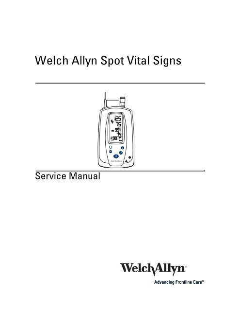
Welch Allyn <strong>Spot</strong> <strong>Vital</strong> <strong>Signs</strong><br />
<strong>Service</strong> <strong>Manual</strong><br />
SYS kPa (mmHg)<br />
DIA kPa (mmHg)<br />
SpO2 %<br />
/ min<br />
<strong>Spot</strong> <strong>Vital</strong> <strong>Signs</strong>
Welch Allyn <strong>Spot</strong> <strong>Vital</strong> <strong>Signs</strong><br />
<strong>Service</strong> <strong>Manual</strong>
ii Welch Allyn <strong>Spot</strong> <strong>Vital</strong> <strong>Signs</strong><br />
Copyright 2007 Welch Allyn. All rights are reserved. No one is permitted to reproduce or duplicate, in any<br />
form, this manual or any part thereof without permission from Welch Allyn.<br />
Welch Allyn assumes no responsibility for any injury to anyone, or for any illegal or improper use of the<br />
product, that may result from failure to use this product in accordance with the instructions, cautions,<br />
warnings, or statement of intended use published in this manual.<br />
Welch Allyn ® and <strong>Spot</strong> <strong>Vital</strong> <strong>Signs</strong> ® are registered trademarks of Welch Allyn.<br />
LNCS is a trademark of, and SET ® , LNOP ® , and Masimo ® are registered trademarks of, Masimo<br />
Corporation. Possession or purchase of a Masimo SpO 2-equipped device does not convey any express or<br />
implied license to use the device with unauthorized sensors or cables which would, alone or in<br />
combination with this device, fall within the scope of one or more of the patents relating to this device.<br />
Nellcor ® and Oxi-Max ® are registered trademarks of Nellcor Puritan Bennett Inc.<br />
Software in this product is Copyright 2007 Welch Allyn or its vendors. All rights are reserved. The software<br />
is protected by United States of America copyright laws and international treaty provisions applicable<br />
worldwide. Under such laws, the licensee is entitled to use the copy of the software incorporated with<br />
this instrument as intended in the operation of the product in which it is embedded. The software may not<br />
be copied, decompiled, reverse-engineered, disassembled, or otherwise reduced to human-perceivable<br />
form. This is not a sale of the software or any copy of the software; all right, title, and ownership of the<br />
software remain with Welch Allyn or its vendors.<br />
For information about any Welch Allyn product, call Welch Allyn Technical Support:<br />
Reorder No. 4200-89E<br />
<strong>Manual</strong> Material No. 706317 Rev. K<br />
Welch Allyn<br />
4341 State Street Road<br />
Skaneateles Falls, NY 13153 USA<br />
Printed in USA<br />
USA +1 800 535 6663<br />
+ 1 315 685 4560<br />
Australia +61 2 9638 3000<br />
+800 074 793<br />
Canada +1 800 561 8797 China +86 21 6327 9631<br />
European Call Center +353 46 90 67790 France +33 1 55 69 58 49<br />
Germany +49 7477 9271 70 Japan +81 3 3219 0071<br />
Latin America +1 305 669 9003 Netherlands +31 157 505 000<br />
Singapore +65 6419 8100 South Africa +27 11 777 7555<br />
United Kingdom +44 207 365 6780 Sweden +46 85 853 6551<br />
0297
<strong>Service</strong> <strong>Manual</strong> iii<br />
Revision Information<br />
Date ECN # Revision Description Originator Approval<br />
3/31/01 A Introduction of <strong>Service</strong> <strong>Manual</strong> JDB JDB<br />
12/17/01 B Correction made to Section 1 regarding temperature accuracy,<br />
Section 2 regarding part numbers, Section 3 regarding error<br />
codes, and updates to the drawings<br />
9/12/02 C Added New PCB layout and schematic for <strong>Spot</strong> Extensions.<br />
Added tool SRC-MAX to tool list in Section 2.3. Removed old PCB<br />
and Old SpO 2 PCB and replaced with new Main PCB and New<br />
SpO 2 PCB in section 2.4. Changed section 4.7 to cover both <strong>Spot</strong><br />
and <strong>Spot</strong> Extensions SpO 2 PCB removal and replacement.<br />
Changed section 5.8 to cover both <strong>Spot</strong> and <strong>Spot</strong> Extension SpO 2<br />
testing. General Spelling and grammar clean up.<br />
02/02/03 5-45656 D Arden document release to SKF. Updated USA <strong>Service</strong> Center<br />
contact information.<br />
05/01/03 5-45893 E Correction to tools required for service. Corrected General<br />
Information phone numbers.<br />
09/16/03 5-46550 F Updates repair BOM. Updated Accessories. Re-formated manual<br />
to meet Welch Allyn service manual work instructions.<br />
12/12/03 5-46989 G Correction to page numbering and to voltage calibrations. Reformatted<br />
all systems of measurement to meet NIST Standards.<br />
Reformatted Appendix E. Corrected grammar and punctuation.<br />
Revised service and support details in Section 1. Removed<br />
schematics.<br />
JDB JDB<br />
JDB JDB<br />
JDB DLK<br />
DLK DLK<br />
DLK DLK<br />
DLK RJS<br />
3/9/06 1007069 H Removed references to Nellcor motion tolerance. AMJ JPK<br />
3/21/07 XXXXXX J SAP new version glitch AMJ FL<br />
3/21/07 1010684 K Update section on Setting the Date and Time. Include testing and<br />
disassembly/assembly for the Masimo SpO 2 feature and<br />
updated repair parts lists.<br />
AMJ FL<br />
Drawings and/or illustrations and/or part numbers in this document are for reference only. For the most<br />
current revision call the Welch Allyn Customer <strong>Service</strong> phone number (see page ii).
iv Welch Allyn <strong>Spot</strong> <strong>Vital</strong> <strong>Signs</strong>
Contents<br />
1 - Introduction . . . . . . . . . . . . . . . . . . . . . . . . . . . . . . . . . . . . . . . . . . . . . 1<br />
Warnings and cautions . . . . . . . . . . . . . . . . . . . . . . . . . . . . . . . . . . . . . . . . . . . . . 1<br />
General warnings . . . . . . . . . . . . . . . . . . . . . . . . . . . . . . . . . . . . . . . . . . . . . . 1<br />
Blood pressure warnings . . . . . . . . . . . . . . . . . . . . . . . . . . . . . . . . . . . . . . . . 3<br />
SpO2 warnings . . . . . . . . . . . . . . . . . . . . . . . . . . . . . . . . . . . . . . . . . . . . . . . . 4<br />
Temperature warnings . . . . . . . . . . . . . . . . . . . . . . . . . . . . . . . . . . . . . . . . . . 5<br />
IR communications port warnings . . . . . . . . . . . . . . . . . . . . . . . . . . . . . . . . . 5<br />
General cautions . . . . . . . . . . . . . . . . . . . . . . . . . . . . . . . . . . . . . . . . . . . . . . 5<br />
Blood pressure cautions. . . . . . . . . . . . . . . . . . . . . . . . . . . . . . . . . . . . . . . . . 6<br />
SpO2 cautions . . . . . . . . . . . . . . . . . . . . . . . . . . . . . . . . . . . . . . . . . . . . . . . . 6<br />
Temperature cautions. . . . . . . . . . . . . . . . . . . . . . . . . . . . . . . . . . . . . . . . . . . 6<br />
Electrostatic discharge (ESD) . . . . . . . . . . . . . . . . . . . . . . . . . . . . . . . . . . . . . . . . 7<br />
Symbols . . . . . . . . . . . . . . . . . . . . . . . . . . . . . . . . . . . . . . . . . . . . . . . . . . . . . . . . 8<br />
Safety symbols. . . . . . . . . . . . . . . . . . . . . . . . . . . . . . . . . . . . . . . . . . . . . . . . 8<br />
Agency symbols. . . . . . . . . . . . . . . . . . . . . . . . . . . . . . . . . . . . . . . . . . . . . . . 8<br />
2 - Overview . . . . . . . . . . . . . . . . . . . . . . . . . . . . . . . . . . . . . . . . . . . . . . . 9<br />
Purpose and scope . . . . . . . . . . . . . . . . . . . . . . . . . . . . . . . . . . . . . . . . . . . . . . . . 9<br />
Other applicable documents. . . . . . . . . . . . . . . . . . . . . . . . . . . . . . . . . . . . . . . . . 9<br />
Contents checklist . . . . . . . . . . . . . . . . . . . . . . . . . . . . . . . . . . . . . . . . . . . . . . . 10<br />
Possible attachments . . . . . . . . . . . . . . . . . . . . . . . . . . . . . . . . . . . . . . . . . . . . . 10<br />
<strong>Service</strong> . . . . . . . . . . . . . . . . . . . . . . . . . . . . . . . . . . . . . . . . . . . . . . . . . . . . . . . . 11<br />
Technical assistance . . . . . . . . . . . . . . . . . . . . . . . . . . . . . . . . . . . . . . . . . . . 11<br />
Field replacement units . . . . . . . . . . . . . . . . . . . . . . . . . . . . . . . . . . . . . . . . 11<br />
<strong>Service</strong> loaners. . . . . . . . . . . . . . . . . . . . . . . . . . . . . . . . . . . . . . . . . . . . . . . 11<br />
<strong>Service</strong> intervals . . . . . . . . . . . . . . . . . . . . . . . . . . . . . . . . . . . . . . . . . . . . . . . . . 12<br />
<strong>Spot</strong> <strong>Vital</strong> <strong>Signs</strong> configurations . . . . . . . . . . . . . . . . . . . . . . . . . . . . . . . . . . . . . . 12<br />
Controls . . . . . . . . . . . . . . . . . . . . . . . . . . . . . . . . . . . . . . . . . . . . . . . . . . . . . . . 13<br />
LCD (liquid crystal display) . . . . . . . . . . . . . . . . . . . . . . . . . . . . . . . . . . . . . . . . . 15<br />
Connections . . . . . . . . . . . . . . . . . . . . . . . . . . . . . . . . . . . . . . . . . . . . . . . . . . . . 16<br />
Blood pressure hose and cuff connections . . . . . . . . . . . . . . . . . . . . . . . . . . . . 17<br />
Temperature probe connection. . . . . . . . . . . . . . . . . . . . . . . . . . . . . . . . . . . . . . 17<br />
SpO2 sensor. . . . . . . . . . . . . . . . . . . . . . . . . . . . . . . . . . . . . . . . . . . . . . . . . 17<br />
Quick reference card . . . . . . . . . . . . . . . . . . . . . . . . . . . . . . . . . . . . . . . . . . 17<br />
DCpower connection . . . . . . . . . . . . . . . . . . . . . . . . . . . . . . . . . . . . . . . . . . 18<br />
Charging the battery . . . . . . . . . . . . . . . . . . . . . . . . . . . . . . . . . . . . . . . . . . . . . . 18<br />
Standby mode. . . . . . . . . . . . . . . . . . . . . . . . . . . . . . . . . . . . . . . . . . . . . . . . . . . 18<br />
v
vi Contents Welch Allyn <strong>Spot</strong> <strong>Vital</strong> <strong>Signs</strong><br />
3 - Functional overview . . . . . . . . . . . . . . . . . . . . . . . . . . . . . . . . . . . . . 19<br />
Power on/off and system check procedure. . . . . . . . . . . . . . . . . . . . . . . . . . . . . 19<br />
Internal configuration mode . . . . . . . . . . . . . . . . . . . . . . . . . . . . . . . . . . . . . . . . 20<br />
Functional verification . . . . . . . . . . . . . . . . . . . . . . . . . . . . . . . . . . . . . . . . . . . . . 21<br />
Temperature functional check. . . . . . . . . . . . . . . . . . . . . . . . . . . . . . . . . . . . 22<br />
SpO2 functional check . . . . . . . . . . . . . . . . . . . . . . . . . . . . . . . . . . . . . . . . . 24<br />
4 - Calibration . . . . . . . . . . . . . . . . . . . . . . . . . . . . . . . . . . . . . . . . . . . . . 25<br />
Connections . . . . . . . . . . . . . . . . . . . . . . . . . . . . . . . . . . . . . . . . . . . . . . . . . . . . 25<br />
Voltage calibration. . . . . . . . . . . . . . . . . . . . . . . . . . . . . . . . . . . . . . . . . . . . . . . . 27<br />
Blood pressure calibration . . . . . . . . . . . . . . . . . . . . . . . . . . . . . . . . . . . . . . . . . 27<br />
Date/time set . . . . . . . . . . . . . . . . . . . . . . . . . . . . . . . . . . . . . . . . . . . . . . . . . . . 28<br />
5 - Troubleshooting . . . . . . . . . . . . . . . . . . . . . . . . . . . . . . . . . . . . . . . . 29<br />
Error codes . . . . . . . . . . . . . . . . . . . . . . . . . . . . . . . . . . . . . . . . . . . . . . . . . . . . . 29<br />
Causes and corrective action . . . . . . . . . . . . . . . . . . . . . . . . . . . . . . . . . . . . . . . 30<br />
Battery voltage check . . . . . . . . . . . . . . . . . . . . . . . . . . . . . . . . . . . . . . . . . . . . . 33<br />
Window display check . . . . . . . . . . . . . . . . . . . . . . . . . . . . . . . . . . . . . . . . . . . . 33<br />
Blood pressure calibration check . . . . . . . . . . . . . . . . . . . . . . . . . . . . . . . . . . . . 33<br />
Temperature functional check. . . . . . . . . . . . . . . . . . . . . . . . . . . . . . . . . . . . 34<br />
Masimo SpO2 functional check . . . . . . . . . . . . . . . . . . . . . . . . . . . . . . . . . . 34<br />
Nellcor SpO2 functional check . . . . . . . . . . . . . . . . . . . . . . . . . . . . . . . . . . . 34<br />
Communication option check . . . . . . . . . . . . . . . . . . . . . . . . . . . . . . . . . . . . 34<br />
Functional testing procedures. . . . . . . . . . . . . . . . . . . . . . . . . . . . . . . . . . . . . . . 34<br />
Current test. . . . . . . . . . . . . . . . . . . . . . . . . . . . . . . . . . . . . . . . . . . . . . . . . . . . . 35<br />
Noise levels . . . . . . . . . . . . . . . . . . . . . . . . . . . . . . . . . . . . . . . . . . . . . . . . . . . . 35<br />
Button test . . . . . . . . . . . . . . . . . . . . . . . . . . . . . . . . . . . . . . . . . . . . . . . . . . . . . 35<br />
Interface test . . . . . . . . . . . . . . . . . . . . . . . . . . . . . . . . . . . . . . . . . . . . . . . . . . . 36<br />
Print quality. . . . . . . . . . . . . . . . . . . . . . . . . . . . . . . . . . . . . . . . . . . . . . . . . . . . . 36<br />
Pneumatic tests . . . . . . . . . . . . . . . . . . . . . . . . . . . . . . . . . . . . . . . . . . . . . . . . . 37<br />
Fail safe (over pressure) test. . . . . . . . . . . . . . . . . . . . . . . . . . . . . . . . . . . . . . . . 37<br />
<strong>Service</strong> work checklist . . . . . . . . . . . . . . . . . . . . . . . . . . . . . . . . . . . . . . . . . . . . 38<br />
6 - Disassembly and repair . . . . . . . . . . . . . . . . . . . . . . . . . . . . . . . . . . 39<br />
Battery disassembly . . . . . . . . . . . . . . . . . . . . . . . . . . . . . . . . . . . . . . . . . . . . . . 40<br />
Temperature disassembly. . . . . . . . . . . . . . . . . . . . . . . . . . . . . . . . . . . . . . . . . . 41<br />
Front housing and key pad disassembly . . . . . . . . . . . . . . . . . . . . . . . . . . . . . . . 42<br />
LCD disassembly . . . . . . . . . . . . . . . . . . . . . . . . . . . . . . . . . . . . . . . . . . . . . . . . 42<br />
Power and battery cable disassembly. . . . . . . . . . . . . . . . . . . . . . . . . . . . . . . . . 43<br />
Main printed circuit board assembly. . . . . . . . . . . . . . . . . . . . . . . . . . . . . . . . . . 44<br />
SpO2 circuit board disassembly . . . . . . . . . . . . . . . . . . . . . . . . . . . . . . . . . . . . . 45<br />
Masimo board . . . . . . . . . . . . . . . . . . . . . . . . . . . . . . . . . . . . . . . . . . . . . . . 45<br />
Nellcor board . . . . . . . . . . . . . . . . . . . . . . . . . . . . . . . . . . . . . . . . . . . . . . . . 47<br />
Pump and valve disassembly . . . . . . . . . . . . . . . . . . . . . . . . . . . . . . . . . . . . . . . 48<br />
7 - Technical overview . . . . . . . . . . . . . . . . . . . . . . . . . . . . . . . . . . . . . . 51<br />
System description . . . . . . . . . . . . . . . . . . . . . . . . . . . . . . . . . . . . . . . . . . . . . . . 51<br />
Battery /charge system . . . . . . . . . . . . . . . . . . . . . . . . . . . . . . . . . . . . . . . . 51
<strong>Service</strong> <strong>Manual</strong> Contents vii<br />
Main CPU power supply. . . . . . . . . . . . . . . . . . . . . . . . . . . . . . . . . . . . . . . . 51<br />
Clock/calendar power . . . . . . . . . . . . . . . . . . . . . . . . . . . . . . . . . . . . . . . . . . 51<br />
Mod B NIBP power . . . . . . . . . . . . . . . . . . . . . . . . . . . . . . . . . . . . . . . . . . . 52<br />
Thermometer power . . . . . . . . . . . . . . . . . . . . . . . . . . . . . . . . . . . . . . . . . . 52<br />
SpO2 power . . . . . . . . . . . . . . . . . . . . . . . . . . . . . . . . . . . . . . . . . . . . . . . . . 52<br />
LCD power . . . . . . . . . . . . . . . . . . . . . . . . . . . . . . . . . . . . . . . . . . . . . . . . . . 52<br />
Communications . . . . . . . . . . . . . . . . . . . . . . . . . . . . . . . . . . . . . . . . . . . . . 52<br />
Interconnect diagram . . . . . . . . . . . . . . . . . . . . . . . . . . . . . . . . . . . . . . . . . . . . . 53<br />
8 - Field replaceable units . . . . . . . . . . . . . . . . . . . . . . . . . . . . . . . . . . . 55<br />
9 - Specifications . . . . . . . . . . . . . . . . . . . . . . . . . . . . . . . . . . . . . . . . . . 59<br />
Patient population . . . . . . . . . . . . . . . . . . . . . . . . . . . . . . . . . . . . . . . . . . . . . . . . 59<br />
Blood pressure . . . . . . . . . . . . . . . . . . . . . . . . . . . . . . . . . . . . . . . . . . . . . . . . . . 59<br />
Temperature . . . . . . . . . . . . . . . . . . . . . . . . . . . . . . . . . . . . . . . . . . . . . . . . . . . . 59<br />
Pulse pximetry . . . . . . . . . . . . . . . . . . . . . . . . . . . . . . . . . . . . . . . . . . . . . . . . . . 60<br />
Masimo sensor accuracy guide . . . . . . . . . . . . . . . . . . . . . . . . . . . . . . . . . . 60<br />
Masimo patents . . . . . . . . . . . . . . . . . . . . . . . . . . . . . . . . . . . . . . . . . . . . . . 60<br />
Nellcor® sensor accuracy guide. . . . . . . . . . . . . . . . . . . . . . . . . . . . . . . . . . 61<br />
Nellcor patents . . . . . . . . . . . . . . . . . . . . . . . . . . . . . . . . . . . . . . . . . . . . . . . 62<br />
Mechanical . . . . . . . . . . . . . . . . . . . . . . . . . . . . . . . . . . . . . . . . . . . . . . . . . . . . . 62<br />
Electrical . . . . . . . . . . . . . . . . . . . . . . . . . . . . . . . . . . . . . . . . . . . . . . . . . . . . . . . 62<br />
Environmental. . . . . . . . . . . . . . . . . . . . . . . . . . . . . . . . . . . . . . . . . . . . . . . . . . . 62<br />
Guidance and manufacturer’s declaration. . . . . . . . . . . . . . . . . . . . . . . . . . . . . . 63<br />
Emissions and immunity information. . . . . . . . . . . . . . . . . . . . . . . . . . . . . . 63<br />
Patents . . . . . . . . . . . . . . . . . . . . . . . . . . . . . . . . . . . . . . . . . . . . . . . . . . . . . . . . 66<br />
Identification label and serial numbering system . . . . . . . . . . . . . . . . . . . . . . . . 67<br />
Firmware identification . . . . . . . . . . . . . . . . . . . . . . . . . . . . . . . . . . . . . . . . . . . . 67<br />
10 - Maintenance . . . . . . . . . . . . . . . . . . . . . . . . . . . . . . . . . . . . . . . . . . 69<br />
Cleaning . . . . . . . . . . . . . . . . . . . . . . . . . . . . . . . . . . . . . . . . . . . . . . . . . . . . . . . 69<br />
<strong>Spot</strong> <strong>Vital</strong> <strong>Signs</strong> . . . . . . . . . . . . . . . . . . . . . . . . . . . . . . . . . . . . . . . . . . . . . . 69<br />
Blood pressure cuff . . . . . . . . . . . . . . . . . . . . . . . . . . . . . . . . . . . . . . . . . . . 69<br />
Cables and pressure hose . . . . . . . . . . . . . . . . . . . . . . . . . . . . . . . . . . . . . . 69<br />
Temperature probe . . . . . . . . . . . . . . . . . . . . . . . . . . . . . . . . . . . . . . . . . . . . 70<br />
SpO2 sensor. . . . . . . . . . . . . . . . . . . . . . . . . . . . . . . . . . . . . . . . . . . . . . . . . 70<br />
Battery removal and replacement. . . . . . . . . . . . . . . . . . . . . . . . . . . . . . . . . . . . 70<br />
Masimo SpO2 calibration check . . . . . . . . . . . . . . . . . . . . . . . . . . . . . . . . . . . . . 71<br />
Nellcor SpO2 functional check . . . . . . . . . . . . . . . . . . . . . . . . . . . . . . . . . . . . . . 71<br />
SpO2 accessory disposal . . . . . . . . . . . . . . . . . . . . . . . . . . . . . . . . . . . . . . . . . . 71<br />
Temperature calibration check . . . . . . . . . . . . . . . . . . . . . . . . . . . . . . . . . . . . . . 71<br />
A - Repair test specifications . . . . . . . . . . . . . . . . . . . . . . . . . . . . . . . . . 73<br />
General unit test . . . . . . . . . . . . . . . . . . . . . . . . . . . . . . . . . . . . . . . . . . . . . . . . . 73<br />
A-D noise test . . . . . . . . . . . . . . . . . . . . . . . . . . . . . . . . . . . . . . . . . . . . . . . 73<br />
Leak test. . . . . . . . . . . . . . . . . . . . . . . . . . . . . . . . . . . . . . . . . . . . . . . . . . . . 73<br />
Inflation test . . . . . . . . . . . . . . . . . . . . . . . . . . . . . . . . . . . . . . . . . . . . . . . . . 73<br />
Dump test . . . . . . . . . . . . . . . . . . . . . . . . . . . . . . . . . . . . . . . . . . . . . . . . . . 73
viii Contents Welch Allyn <strong>Spot</strong> <strong>Vital</strong> <strong>Signs</strong><br />
Pneumatic calibration . . . . . . . . . . . . . . . . . . . . . . . . . . . . . . . . . . . . . . . . . . 74<br />
Pneumatic accuracy test . . . . . . . . . . . . . . . . . . . . . . . . . . . . . . . . . . . . . . . 74<br />
Valve control test . . . . . . . . . . . . . . . . . . . . . . . . . . . . . . . . . . . . . . . . . . . . . 74<br />
Voltage calibration . . . . . . . . . . . . . . . . . . . . . . . . . . . . . . . . . . . . . . . . . . . . 74<br />
Blank mode current test. . . . . . . . . . . . . . . . . . . . . . . . . . . . . . . . . . . . . . . . 74<br />
Back light (Idle) current test . . . . . . . . . . . . . . . . . . . . . . . . . . . . . . . . . . . . . 75<br />
Valve/pump mode current test . . . . . . . . . . . . . . . . . . . . . . . . . . . . . . . . . . . 75<br />
Interface test . . . . . . . . . . . . . . . . . . . . . . . . . . . . . . . . . . . . . . . . . . . . . . . . 75<br />
Temperature option requirements . . . . . . . . . . . . . . . . . . . . . . . . . . . . . . . . . . . 75<br />
Accuracy test . . . . . . . . . . . . . . . . . . . . . . . . . . . . . . . . . . . . . . . . . . . . . . . . 75<br />
Temperature probe test . . . . . . . . . . . . . . . . . . . . . . . . . . . . . . . . . . . . . . . . 75<br />
SpO2 option requirements . . . . . . . . . . . . . . . . . . . . . . . . . . . . . . . . . . . . . . . . . 75<br />
SpO2 functional test . . . . . . . . . . . . . . . . . . . . . . . . . . . . . . . . . . . . . . . . . . . 75<br />
SpO2 mode current test. . . . . . . . . . . . . . . . . . . . . . . . . . . . . . . . . . . . . . . . 75<br />
Fail safe test . . . . . . . . . . . . . . . . . . . . . . . . . . . . . . . . . . . . . . . . . . . . . . . . . . . . 76<br />
Over pressure test . . . . . . . . . . . . . . . . . . . . . . . . . . . . . . . . . . . . . . . . . . . . 76<br />
Over 15 mmHg. . . . . . . . . . . . . . . . . . . . . . . . . . . . . . . . . . . . . . . . . . . . . . . 76<br />
B - Supplies and Accessories . . . . . . . . . . . . . . . . . . . . . . . . . . . . . . . . 77<br />
Latex-free blood pressure . . . . . . . . . . . . . . . . . . . . . . . . . . . . . . . . . . . . . . . . . . 77<br />
Pulse oximetry accessories and supplies . . . . . . . . . . . . . . . . . . . . . . . . . . . . . . 78<br />
Masimo . . . . . . . . . . . . . . . . . . . . . . . . . . . . . . . . . . . . . . . . . . . . . . . . . . . . 78<br />
Nellcor . . . . . . . . . . . . . . . . . . . . . . . . . . . . . . . . . . . . . . . . . . . . . . . . . . . . . 79<br />
Temperature . . . . . . . . . . . . . . . . . . . . . . . . . . . . . . . . . . . . . . . . . . . . . . . . . . . . 80<br />
Mounting . . . . . . . . . . . . . . . . . . . . . . . . . . . . . . . . . . . . . . . . . . . . . . . . . . . . . . 80<br />
Extended warranty . . . . . . . . . . . . . . . . . . . . . . . . . . . . . . . . . . . . . . . . . . . . . . . 80<br />
Miscellaneous. . . . . . . . . . . . . . . . . . . . . . . . . . . . . . . . . . . . . . . . . . . . . . . . . . . 81<br />
C - Miscellaneous Mounting Accessories. . . . . . . . . . . . . . . . . . . . . . . 83<br />
Wall mount kit (REF 4200-62) . . . . . . . . . . . . . . . . . . . . . . . . . . . . . . . . . . . . . . . 83<br />
Mobile stand kit (REF 4200-60) . . . . . . . . . . . . . . . . . . . . . . . . . . . . . . . . . . . . . 84<br />
IV pole mount accessory (REF 4200-64). . . . . . . . . . . . . . . . . . . . . . . . . . . . . . . 85<br />
Anti-theft kit (REF 4200-70) . . . . . . . . . . . . . . . . . . . . . . . . . . . . . . . . . . . . . . . . 86<br />
Transformer mounting plate accessory (REF 4200-75). . . . . . . . . . . . . . . . . . . . 87<br />
IR dongle mounting accessory (REF 4200-170) . . . . . . . . . . . . . . . . . . . . . . . . . 88<br />
Warranty . . . . . . . . . . . . . . . . . . . . . . . . . . . . . . . . . . . . . . . . . . . . . . . . . 89<br />
<strong>Spot</strong> <strong>Vital</strong> <strong>Signs</strong>. . . . . . . . . . . . . . . . . . . . . . . . . . . . . . . . . . . . . . . . . . . . . . . . . . 89<br />
Accessories . . . . . . . . . . . . . . . . . . . . . . . . . . . . . . . . . . . . . . . . . . . . . . . . . . . . 89
1<br />
Introduction<br />
Welch Allyn has updated the <strong>Spot</strong> <strong>Vital</strong> <strong>Signs</strong> from its original configuration; offering a<br />
Pressure Preset option (Version 2, page 14) instead of a Print option (Version 1, page 13).<br />
In addition, some Version 2 configurations offer Masimo SpO 2 technology.<br />
Warnings and cautions<br />
General warnings<br />
Table 1. Version comparison<br />
Function/Appearance Version 1<br />
(serial number less than<br />
200705000)<br />
Version 2<br />
(serial number 200705000<br />
and above)<br />
Available option Print Pressure Preset<br />
Available SpO 2 capability Nellcor Masimo or Nellcor<br />
Bezel and switch array color Black bezel/multi-colored<br />
switch array<br />
Familiarize all operating personnel with the general safety information in this summary.<br />
Specific warnings and cautions are also found throughout this manual. Such specific<br />
warnings and cautions may not appear here in this summary.<br />
A warning statement in this manual identifies a condition or practice, which if not<br />
corrected or discontinued immediately, could lead to patient injury, illness, or death.<br />
WARNING The Welch Allyn <strong>Spot</strong> <strong>Vital</strong> <strong>Signs</strong> is designed for use by medical<br />
clinicians. Although this manual may illustrate medical spot check techniques,<br />
only a trained clinician who knows how to take and interpret a patient’s vital signs<br />
should use this system.<br />
WARNING The information in this manual is a comprehensive guide to the<br />
operation of the Welch Allyn <strong>Spot</strong> <strong>Vital</strong> <strong>Signs</strong>. To achieve satisfactory results, you<br />
should read the manual thoroughly before attempting to use the device.<br />
WARNING <strong>Spot</strong> <strong>Vital</strong> <strong>Signs</strong> is not intended to take measurements on neonatal<br />
patients. The AAMI SP10:1992 standard defines neonates as children 28 days or<br />
less of age if born at term (37 weeks gestation or more); otherwise up to 44<br />
gestational weeks.<br />
WARNING The Welch Allyn <strong>Spot</strong> <strong>Vital</strong> <strong>Signs</strong> is not defibrillator proof.<br />
Blue<br />
1
2 Introduction Welch Allyn <strong>Spot</strong> <strong>Vital</strong> <strong>Signs</strong><br />
WARNING The Welch Allyn <strong>Spot</strong> <strong>Vital</strong> <strong>Signs</strong> is not intended for continuous<br />
monitoring. Do not leave the device unattended while taking measurements on a<br />
patient.<br />
WARNING To ensure patient safety, use only accessories and supplies (i.e.,<br />
blood pressure cuffs, hoses, temperature probes, SpO 2 sensors, etc.)<br />
recommended for or supplied with <strong>Spot</strong> <strong>Vital</strong> <strong>Signs</strong>. Using unapproved<br />
accessories with <strong>Spot</strong> <strong>Vital</strong> <strong>Signs</strong> can affect patient and/or operator safety.<br />
WARNING This device is not suitable for use in the presence of a flammable<br />
anesthetic mixture with air or oxygen or nitrous oxide. An explosion may result.<br />
WARNING Avoid compression of the blood pressure cuff tubing or pressure<br />
hose of the Welch Allyn <strong>Spot</strong> <strong>Vital</strong> <strong>Signs</strong>. Compression of the cuff tubing or<br />
pressure hose may cause system errors to occur in the device.<br />
WARNING Care should be taken to prevent water or other fluid from entering<br />
any connectors on the device. Should this occur, the connectors should be dried<br />
with warm air. All operating functions should then be checked for proper<br />
operation.<br />
WARNING Any <strong>Spot</strong> <strong>Vital</strong> <strong>Signs</strong> which has been dropped or damaged should be<br />
checked by qualified service personnel to ensure proper operation prior to use. Do<br />
not use the Welch Allyn <strong>Spot</strong> <strong>Vital</strong> <strong>Signs</strong> if you notice any signs of damage.<br />
Contact the Welch Allyn Customer <strong>Service</strong> Department for assistance.<br />
WARNING Every three months, inspect the temperature probe, SpO 2 cord, and<br />
accessories for fraying or other damage. Replace as necessary.<br />
WARNING There are no user-serviceable parts inside the device other than<br />
battery replacement. Refer <strong>Spot</strong> <strong>Vital</strong> <strong>Signs</strong> to the Authorized <strong>Service</strong> Center.<br />
WARNING The <strong>Spot</strong> <strong>Vital</strong> <strong>Signs</strong> should not be used on patients who are linked<br />
to heart/lung machines.<br />
WARNING The <strong>Spot</strong> <strong>Vital</strong> <strong>Signs</strong> does not operate effectively on patients who are<br />
experiencing convulsions or tremors.<br />
WARNING This device complies with current required standards for<br />
electromagnetic interference and should not present problems to other<br />
equipment or be affected by other devices. As a precaution, avoid using this<br />
device in close proximity to other equipment.<br />
WARNING This device is not intended for hand-held use during operation.<br />
WARNING Welch Allyn recommends leaving the battery in the device,<br />
regardless if the device is not used for long periods of time, since there is no<br />
hazard of leaving the battery in the device.<br />
WARNING Do not autoclave.<br />
WARNING Welch Allyn is not responsible for the integrity of any mounting<br />
installation. Welch Allyn recommends that the customer contact their Biomedical<br />
Engineering Department or maintenance service to ensure professional<br />
installation for safety and reliability of any mounting accessory.
<strong>Service</strong> <strong>Manual</strong> Introduction 3<br />
Blood pressure warnings<br />
WARNING To ensure pediatric blood pressure accuracy and safety, the Welch<br />
Allyn Child Print Cuff (5200-03), the Welch Allyn Small Child Durable One-Piece<br />
Cuff (5082-203-3), and the Welch Allyn Small Child Disposable One-Piece Cuff<br />
(5082-93-3) are the smallest cuffs allowed for use with young children and infants.<br />
The circumference of the child’s arm must fit within the range markings on the<br />
cuff.<br />
WARNING You may experience inaccurate blood pressure measurements if<br />
blood pressure cuffs and/or hoses other than those provided by Welch Allyn for<br />
the <strong>Spot</strong> <strong>Vital</strong> <strong>Signs</strong> are used.<br />
WARNING Patients who are experiencing moderate to severe arrhythmias may<br />
give inaccurate blood pressure measurements.<br />
WARNING When several blood pressure measurements are taken on the same<br />
patient, it is recommended that the blood pressure cuff site and extremity are<br />
checked regularly for possible ischemia, purpura, and/or neuropathy.<br />
WARNING Do not change the connector(s) on the blood pressure cuff tubing of<br />
this device to luer type. Luer type connectors are commonly used in intravenous<br />
infusion systems. Using the luer connectors on blood pressure cuff tubing<br />
creates the risk that the blood pressure tubing could be mistakenly connected to<br />
a patient's intravenous line, resulting in the introduction of air into the patient's<br />
circulatory system.
4 Introduction Welch Allyn <strong>Spot</strong> <strong>Vital</strong> <strong>Signs</strong><br />
SpO 2 warnings<br />
WARNING Only use <strong>Spot</strong> <strong>Vital</strong> <strong>Signs</strong> with Masimo or Nellcor SpO 2 option with<br />
Masimo or Nellcor brand sensors and accessories, respectively. Using the wrong<br />
or unapproved sensors or cables may cause improper performance.<br />
WARNING The SpO 2 sensors and extension cables are intended for use only for<br />
pulse oximetry measurements. Do not attempt to connect these cables to a PC<br />
or any similar device.<br />
WARNING Before use, carefully read the sensor’s directions for use, including<br />
all warnings, cautions, and instructions.<br />
WARNING Do not use a damaged sensor or SpO 2 cable. Do not use a sensor<br />
with exposed optical components.<br />
WARNING Tissue damage can be caused by incorrect application or duration of<br />
use of an SpO 2 sensor. Inspect the sensor site as directed in the sensor’s<br />
Directions for Use.<br />
WARNING Do not use the sensors during magnetic resonance imaging (MRI)<br />
scanning. Induced current could potentially cause burns. The pulse oximeter may<br />
affect the MRI image, and the MRI unit may affect the accuracy of the pulse<br />
oximetry measurements.<br />
WARNING Certain ambient environmental conditions, sensor application errors,<br />
and certain patient conditions may affect SpO 2 readings and pulse signal.<br />
WARNING Do not immerse the sensor or patient cables in water, solvents, or<br />
cleaning solutions (the sensors and connections are not waterproof). Do not use<br />
irradiation, steam, or ethylene oxide for sterilization.<br />
WARNING Do not use the SpO 2 cable or power cord to lift the unit because the<br />
cable or cord could disconnect from the unit, causing the unit to drop on the<br />
patient.<br />
WARNING The SpO 2 in the Welch Allyn <strong>Spot</strong> <strong>Vital</strong> signs is not intended for use<br />
as an apnea monitor.<br />
WARNING Consider the SpO 2 an early warning device. As a trend toward<br />
patient deoxygenation is indicated, use laboratory instruments to analyze blood<br />
samples to completely understand the patient’s condition.
<strong>Service</strong> <strong>Manual</strong> Introduction 5<br />
Temperature warnings<br />
IR communications port warnings<br />
General cautions<br />
WARNING Single-use, disposable probe covers, available from Welch Allyn, limit<br />
patient cross-contamination. The use of any other probe cover or the failure to<br />
use a probe cover may produce temperature errors and is specifically not<br />
recommended.<br />
WARNING Use only oral probes (blue cap) for taking oral and axillary<br />
temperatures. Use only rectal probes (red cap) for taking rectal temperatures. The<br />
use of the wrong probe may produce temperature errors.<br />
WARNING Do not allow the tip of the temperature probe to come into contact<br />
with any heat source (e.g., hands or fingers) prior to taking a temperature<br />
measurement. If this occurs, discard the probe cover and start the temperature<br />
determination again.<br />
WARNING Long-term continuous monitoring beyond three to five minutes is<br />
not recommended in any mode.<br />
WARNING The Welch Allyn <strong>Spot</strong> <strong>Vital</strong> <strong>Signs</strong> contains an infrared<br />
communications port for isolated communications with external devices. The port<br />
is located on the side of the device to preclude direct eye contact on a continual<br />
basis when viewing the display. As a precaution, do not look directly into the<br />
infrared port during operation.<br />
A caution statement in this manual identifies a condition or practice, which if not<br />
corrected or discontinued immediately, could lead to equipment failure, equipment<br />
damage, or data loss.<br />
Caution If the accuracy of any measurement is in question, check the patient's<br />
vital sign(s) by an alternate method, then check to make sure the device is<br />
functioning properly.<br />
Caution Ensure the device is placed on a secure surface or use one of the<br />
optional mounting accessories.<br />
Caution Do not place fluids on the device.
6 Introduction Welch Allyn <strong>Spot</strong> <strong>Vital</strong> <strong>Signs</strong><br />
Blood pressure cautions<br />
SpO 2 cautions<br />
Temperature cautions<br />
Caution Extremity and blood pressure cuff motion should be minimized during<br />
blood pressure determinations.<br />
Caution If the blood pressure cuff is not at heart level, the difference in reading<br />
due to the hydrostatic effect should be noted. The value of 1.80 mmHg must be<br />
added to the displayed reading for every inch (2.5 cm) above heart level. The<br />
value of 1.80 mmHg must be subtracted from the displayed reading for every<br />
inch (2.5 cm) below heart level.<br />
Caution Proper blood pressure cuff size and placement is essential to the<br />
accuracy of the blood pressure determination.<br />
Caution When measuring blood pressure on children younger than 3 years of<br />
age, it is recommended that the Pressure Preset (initial inflation pressure) be set<br />
at 160 mmHg or lower.<br />
Caution The pulse oximeter is calibrated to determine the percentage of<br />
arterial oxygen saturation of functional hemoglobin. Significant levels of<br />
dysfunctional hemoglobin such as carboxyhemoglobin or methemoglobin may<br />
affect the accuracy of the measurement.<br />
Caution Physiological conditions, medical procedures, or external agents that<br />
may interfere with the pulse oximeter’s ability to detect and display<br />
measurements include dysfunctional hemoglobin, arterial dyes, low perfusion,<br />
dark pigment, and externally applied coloring agents such as nail polish, dye, or<br />
pigmented cream.<br />
Caution Some sensors may not be appropriate for a particular patient. If at least<br />
15 seconds of perfusion pulses cannot be observed for a given sensor, change<br />
sensor location or sensor type for perfusion to resume.<br />
Caution When selecting a sensor, consider the patient’s weight and activity<br />
level, the adequacy of perfusion, the available sensor sites, the need for sterility,<br />
and the anticipated duration of monitoring.<br />
Caution The Welch Allyn <strong>Spot</strong> <strong>Vital</strong> <strong>Signs</strong> is FDA cleared to measure the axillary<br />
temperature in Normal Mode for children under the age of 4. Normal Mode<br />
axillary temperatures may not be accurate on older children or adults. THE<br />
WELCH ALLYN SPOT VITAL SIGNS IS NOT INTENDED TO BE USED ON<br />
NEONATAL PATIENTS.
<strong>Service</strong> <strong>Manual</strong> Introduction 7<br />
Electrostatic discharge (ESD)<br />
Electrostatic discharge is a sudden current flowing from a charged object to another<br />
object or to ground. Electrostatic charges can accomulate on common items such as<br />
foam drinking cups, cellophane tape, synthetic clothing, untreated foam packaging<br />
material, and untreated plastic bags and work folders, to name only a few.<br />
Electronic components and assemblies, if not properly protected against ESD, can be<br />
permanently damaged or destroyed when near or in contact with electrostatically charged<br />
objects. When you handle components or assemblies that are not in protective bags and<br />
you are not sure whether they are static-sensitive, assume that they are static-sensitive<br />
and handle them accordingly.<br />
Perform all service procedures in a static-protected environment. Always use<br />
techniques and equipment designed to protect personnel and equipment from<br />
electrostatic discharge.<br />
Remove static-sensitive components and assemblies from their static-shielding bags<br />
only at static-safe workstations - a properly grounded table and grounded floor mat -<br />
and only when you are wearing a grounded wrist strap (with a resistor of at least 1<br />
megohm in series) or other grounding device.<br />
Use only grounded tools when inserting, adjusting, or removing static-sensitive<br />
components and assemblies.<br />
Remove or insert static-sensitive components and assemblies only with monitor<br />
power turned off.<br />
Insert and seal static-sensitive components and assemblies into their original staticshielding<br />
bags before removing them from static-protected areas.<br />
Always test your ground strap, bench mat, conductive work surface, and ground cord<br />
before removing components and assemblies from their protective bags and before<br />
beginning any disassembly or assembly procedures.
8 Introduction Welch Allyn <strong>Spot</strong> <strong>Vital</strong> <strong>Signs</strong><br />
Symbols<br />
Safety symbols<br />
Agency symbols<br />
The following symbols are associated with the <strong>Spot</strong> <strong>Vital</strong> <strong>Signs</strong>.<br />
s<br />
C US<br />
166292<br />
0297<br />
EC REP<br />
Identifies information within the<br />
manual to avoid injury or equipment<br />
failure.<br />
Caution: consult accompanying<br />
documents<br />
Type BF Equipment Internally Powered, Lead Acid<br />
Pb Battery<br />
Handle with Care Transport Temperature<br />
Storage Humidity Recycle<br />
Class II Equipment Equipment is not protected against<br />
IPXØ<br />
the ingress of liquid.<br />
Do not dispose of this product as unsorted municipal waste. Prepare this product for reuse or<br />
separate collection as specified by Directive 2002/96/EC of the European Parliament and the<br />
Council of the European Union on Waste Electronic and Electrical Equipment (WEEE). If this<br />
product is contaminated, this directive does not apply.<br />
For more specific disposal information, see www.welchallyn.com/weee,<br />
or contact Welch Allyn Customer <strong>Service</strong> at +44 207 365 6780.<br />
Mode of Operation: Continuous<br />
CERTIFIED TO:<br />
CAN/CSA STD C22.2 NO. 601.1<br />
CONFORMS TO:<br />
UL STD 60601-1<br />
IEC 60601-1<br />
The CE mark on this product indicates that it has been tested to and conforms with<br />
the provisions noted within the 93/42/EEC Medical Device Directive.<br />
European Regulatory Manager<br />
Welch Allyn Ltd.<br />
Navan Business Park • Dublin Road Navan, County Meath, Republic of Ireland<br />
Tel.: +353 46 90 67700 Fax: +353 46 90 67756
2<br />
Overview<br />
Purpose and scope<br />
The <strong>Spot</strong> <strong>Vital</strong> <strong>Signs</strong> <strong>Service</strong> <strong>Manual</strong> is intended as a reference for maintenance and repair<br />
to the field replaceable unit (FRU) level and are listed on page 55. This manual provides<br />
the technical qualified service person with troubleshooting information, repair procedures,<br />
and calibration and performance verification instructions. A technical overview of the <strong>Spot</strong><br />
subsystems is provided as an introduction to the device’s circuitry and pneumatics.<br />
This manual is intended for the technical qualified service person. <strong>Service</strong> training classes<br />
on Welch Allyn’s products are available. Contact Welch Allyn Technical <strong>Service</strong> for<br />
information.<br />
Other applicable documents<br />
The <strong>Spot</strong> <strong>Vital</strong> <strong>Signs</strong> Directions for Use manual is also available. Refer to this document for<br />
information other than maintenance and repair.<br />
Welch Allyn 9600 Plus Calibration Tester Directions for Use - for all models.<br />
Masimo Directions for Use - for models 42M0B and 42MTB<br />
Nellcor Directions for Use - for models 42N0B and 42NTB<br />
9
10 Overview Welch Allyn <strong>Spot</strong> <strong>Vital</strong> <strong>Signs</strong><br />
Contents checklist<br />
Unpack the Welch Allyn <strong>Spot</strong> <strong>Vital</strong> <strong>Signs</strong> and applicable accessories, identify each item<br />
with the following checklist and inspect for missing items. Retain the shipping materials in<br />
the event of shipping damage or for return, if necessary, to Welch Allyn for repair or<br />
warranty service. All <strong>Spot</strong> <strong>Vital</strong> <strong>Signs</strong> include the following components:<br />
<strong>Spot</strong> <strong>Vital</strong> <strong>Signs</strong> Device. This device automatically measures and displays blood<br />
pressure and pulse rate. Options include thermometry and pulse oximetry.<br />
Directions for Use <strong>Manual</strong>. Read this manual thoroughly before using <strong>Spot</strong> <strong>Vital</strong> <strong>Signs</strong>.<br />
Save this manual for reference.<br />
Warranty Card. This card validates the <strong>Spot</strong> <strong>Vital</strong> <strong>Signs</strong> warranty. Fill out the warranty<br />
card and mail it today.<br />
Blood Pressure Cuff. Latex free blood pressure cuff with connectors. Other size cuffs are<br />
available separately.<br />
Blood Pressure Hose. Latex-free pressure hose with connectors to attach various sizes of<br />
blood pressure cuffs to the <strong>Spot</strong> <strong>Vital</strong> <strong>Signs</strong>.<br />
AC Power Transformer and Cord Assembly. Provides power to the <strong>Spot</strong> <strong>Vital</strong> <strong>Signs</strong> and<br />
charges the internal battery.<br />
Quick Reference/Error Code Card. Attach this quick operating and error code guide to<br />
the device handle, mobile stand, or wall mount.<br />
Possible attachments<br />
<strong>Spot</strong> <strong>Vital</strong> <strong>Signs</strong> may include the following items based on the model and accessories<br />
purchased:<br />
SureTemp Temperature Probe and Covers. One oral temperature probe (blue cap) and<br />
one box of 25 single-use, disposable probe covers.<br />
Pulse Oximetry (SpO 2 ). The finger clip SpO 2 sensor and extension cable are for use<br />
with adult and pediatric patients. Other sensors are available separately.
<strong>Service</strong> <strong>Manual</strong> Overview 11<br />
<strong>Service</strong><br />
Technical assistance<br />
A Welch Allyn <strong>Service</strong> Center must perform all repairs on products under warranty.<br />
Unauthorized repairs will void the warranty. Qualified electronics personnel or a Welch<br />
Allyn <strong>Service</strong> Center should repair products out of warranty.<br />
If you have an equipment problem that you cannot resolve, call the Welch Allyn <strong>Service</strong><br />
Center nearest you for assistance. Technical service telephone support is available on<br />
normal business days.<br />
If you are advised to return a product to Welch Allyn for repair or routine maintenance,<br />
schedule the repair with the service center nearest you.<br />
Before returning a product for repair, you must obtain authorization from Welch Allyn.<br />
<strong>Service</strong> personnel will give you a <strong>Service</strong> Notification number. Returns without a <strong>Service</strong><br />
Notification number will not be accepted for delivery.<br />
If you need to return the <strong>Spot</strong> <strong>Vital</strong> <strong>Signs</strong> for service:<br />
Remove all hoses, cables, sensors, power cords, and any ancillary products not<br />
associated with the problem.<br />
Whenever possible, use the original shipping carton and packing materials.<br />
Include a packing list and the Welch Allyn <strong>Service</strong> Notification number.<br />
Note the <strong>Service</strong> Notification number on the outside of your shipping container.<br />
It is recommended to insure all returned goods. The sender may initiate any claims for<br />
loss or damage to the product.<br />
Field replacement units<br />
<strong>Service</strong> loaners<br />
Caution Unauthorized repairs will void the warranty.<br />
Included with the <strong>Service</strong> <strong>Manual</strong> is a complete list of field replacement units. Order<br />
spare parts from your local Welch Allyn <strong>Service</strong> Center.<br />
<strong>Service</strong> loaners are provided, on request, if a Welch Allyn <strong>Service</strong> Center provides repair<br />
service. Loaners for products repaired while under the original warranty, or while under<br />
service contract, are provided free of charge and are shipped within 48 hours of<br />
notification of need.<br />
For service repairs outside of warranty or contract, loaners are available for a nominal<br />
charge and shipment is subject to availability. Loaners are shipped pre-paid; however, this<br />
charge is added to the service charges.
12 Overview Welch Allyn <strong>Spot</strong> <strong>Vital</strong> <strong>Signs</strong><br />
<strong>Service</strong> intervals<br />
Verify <strong>Spot</strong> <strong>Vital</strong> <strong>Signs</strong> annually for blood pressure calibration, temperature, and SpO 2<br />
accuracy.<br />
<strong>Spot</strong> <strong>Vital</strong> <strong>Signs</strong> configurations<br />
Table 2. Available Versions of <strong>Spot</strong> <strong>Vital</strong> <strong>Signs</strong><br />
REF Description<br />
4200B <strong>Spot</strong> <strong>Vital</strong> <strong>Signs</strong> with blood pressure only<br />
420TB <strong>Spot</strong> <strong>Vital</strong> <strong>Signs</strong> with blood pressure and SureTemp thermometer<br />
42MOB <strong>Spot</strong> <strong>Vital</strong> <strong>Signs</strong> with blood pressure and Masimo SpO 2 *<br />
42NOB <strong>Spot</strong> <strong>Vital</strong> <strong>Signs</strong> with blood pressure and Nellcor SpO2 42MTB <strong>Spot</strong> <strong>Vital</strong> <strong>Signs</strong> with blood pressure, SureTemp thermometer, and Masimo SpO2 *<br />
42NTB <strong>Spot</strong> <strong>Vital</strong> <strong>Signs</strong> with blood pressure, SureTemp thermometer, and Nellcor SpO2 * Version 2 configurations only.
<strong>Service</strong> <strong>Manual</strong> Overview 13<br />
Controls<br />
Printer: press to print the<br />
measurements (Version 1 only).<br />
Mode Button:<br />
holding for 2 seconds while<br />
the display is active turns off/on<br />
the backlight.<br />
in Standby Mode, recalls the<br />
last patient information.<br />
with the temperature probe<br />
removed from the probe holder,<br />
switches the temperature from<br />
Oral to Axillary Mode.<br />
Figure 1. <strong>Spot</strong> <strong>Vital</strong> <strong>Signs</strong> with SureTemp Plus Thermometer (Version 1)<br />
MODE<br />
SYS kPa (mmHg)<br />
DIA kPa (mmHg)<br />
SpO2 %<br />
/ min<br />
M P<br />
C<br />
Thermometer Eject Button: push to<br />
remove used temperature probe cover.<br />
Next Patient/Clear/Cancel Button:<br />
active display: clears the display.<br />
in Standby Mode: recalls the last patient<br />
information. Pressing a second time clears<br />
the screen.<br />
cancels an active blood pressure<br />
measurement and deflates the cuff.<br />
Blood Pressure Start/Stop Button:<br />
initiates a new blood pressure cycle.<br />
Pressing again cancels an active blood<br />
pressure measurement and deflates the cuff.<br />
Pressure Hose Connector: port for blood<br />
pressure hose.<br />
Power Button: controls power to the device.
14 Overview Welch Allyn <strong>Spot</strong> <strong>Vital</strong> <strong>Signs</strong><br />
Pressure Preset Button: press<br />
to change the factory inflation<br />
default for one reading (Version 2<br />
only).<br />
Mode Button:<br />
holding for 2 seconds while<br />
the display is active turns off/on<br />
the backlight.<br />
in Standby Mode, recalls the<br />
last patient information.<br />
with the temperature probe<br />
removed from the probe holder,<br />
switches the temperature from<br />
Oral to Axillary Mode.<br />
Figure 2. <strong>Spot</strong> <strong>Vital</strong> <strong>Signs</strong> with SureTemp Plus Thermometer (Version 2)<br />
SYS kPa (mmHg)<br />
DIA kPa (mmHg)<br />
SpO2 %<br />
/ min<br />
<strong>Spot</strong> <strong>Vital</strong> <strong>Signs</strong><br />
Thermometer Eject Button: push to<br />
remove used temperature probe cover.<br />
Next Patient/Clear/Cancel Button:<br />
active display: clears the display.<br />
in Standby Mode: recalls the last patient<br />
information. Pressing a second time clears<br />
the screen.<br />
cancels an active blood pressure<br />
measurement and deflates the cuff.<br />
Blood Pressure Start/Stop Button:<br />
initiates a new blood pressure cycle.<br />
Pressing again cancels an active blood<br />
pressure measurement and deflates the cuff.<br />
Pressure Hose Connector: port for blood<br />
pressure hose.<br />
Power Button: controls power to the device.
<strong>Service</strong> <strong>Manual</strong> Overview 15<br />
LCD (liquid crystal display)<br />
Option no longer available.<br />
Date/Time: indicates that the<br />
user must set/re-set the<br />
current date and time.<br />
Measurement Indicator:<br />
displays the blood<br />
pressure, SpO2, or<br />
temperature icon as <strong>Spot</strong><br />
<strong>Vital</strong> <strong>Signs</strong> is taking the<br />
respective measurement.<br />
Thermometer Mode icon:<br />
shows temperature mode (for<br />
devices with SureTemp only).<br />
The LCD may indicate any of the following: systolic blood pressure (mmHg or kPa),<br />
diastolic blood pressure (mmHg or kPa), temperature (°F or °C), thermometer mode,<br />
pulse rate, pulse signal level, SpO 2, MAP (mmHg or kPa), and battery charge level.<br />
.<br />
Temperature Probe Problem:<br />
indicates a temperature probe problem<br />
(for devices with SureTemp only).<br />
SYS mmHg<br />
DIA mmHg<br />
SpO2 %<br />
/ min<br />
Battery Charging: indicates the device is<br />
powered through the AC power transformer.<br />
M P<br />
Systolic and Diastolic display:<br />
if MAP is turned on, the screen<br />
toggles between the systolic and<br />
diastolic values, and the word<br />
“MAP” and the MAP value.<br />
SpO 2 Display: shows the percent saturation of arterial<br />
hemoglobin (for devices with SpO 2 only).<br />
Pulse Display: shows the pulse rate.<br />
Temperature Display and Indicator: shows the<br />
temperature in Fahrenheit or Celsius (for devices with<br />
SureTemp only).<br />
Monitor Mode Temperature: indicates the thermometer is<br />
in Monitor Mode (for devices with SureTemp only).<br />
Out-of-range indicator: shows the patient’s temperature<br />
reading above or below the measurement range limits (for<br />
devices with SureTemp only).<br />
Icon not used.<br />
Battery Level indicator: displays the battery charge level.
16 Overview Welch Allyn <strong>Spot</strong> <strong>Vital</strong> <strong>Signs</strong><br />
Connections<br />
Temperature Probe Holder:<br />
storage space for the<br />
temperature probe when not in<br />
use (for devices with SureTemp<br />
only).<br />
Suretemp Thermometer<br />
Connection Port (for<br />
devices with SureTemp only).<br />
Use the following instructions to connect the blood pressure hose, thermometer probe,<br />
and optional attachments to the <strong>Spot</strong> <strong>Vital</strong> <strong>Signs</strong>.<br />
Figure 3. <strong>Spot</strong> Side and Rear Panel Connections<br />
Battery Door<br />
Probe Cover Storage Compartment: storage<br />
space for one box of probe covers.<br />
Threaded Insert: to mount the<br />
<strong>Spot</strong> <strong>Vital</strong> <strong>Signs</strong> to a mobile stand.<br />
SpO 2 Cable Connection Port<br />
(for units with SpO 2 only)<br />
IR Data Interface:<br />
Port for<br />
communicating with<br />
an external device.<br />
DC Power<br />
Connection Port
<strong>Service</strong> <strong>Manual</strong> Overview 17<br />
Blood pressure hose and cuff connections<br />
Have available the <strong>Spot</strong> <strong>Vital</strong> <strong>Signs</strong>, blood pressure cuff, and blood pressure hose.<br />
1. Inspect the pressure hose; note that one end has a connector fitting and the other<br />
end does not. Attach the end without the connector fitting to the pressure hose<br />
connector (see page 14). Verify that the pressure hose is completely inserted over the<br />
connector and that the fit is snug.<br />
2. Join the other end of the pressure hose to the blood pressure cuff pneumatic tubing.<br />
Twist the connectors together until finger-tight. DO NOT OVERTIGHTEN.<br />
Temperature probe connection<br />
SpO 2 sensor<br />
Quick reference card<br />
The Welch Allyn <strong>Spot</strong> <strong>Vital</strong> <strong>Signs</strong> is available with two probes — one for oral/axillary<br />
temperatures (blue cap), and one for rectal temperatures (red cap). The rectal probe is an<br />
accessory item that is ordered separately.<br />
Press down on the tab on top of the connector and insert the connector into the<br />
temperature probe connector port on the back of the <strong>Spot</strong> <strong>Vital</strong> <strong>Signs</strong>. The probe<br />
connector only fits into <strong>Spot</strong> <strong>Vital</strong> <strong>Signs</strong> one way. Verify the connector clicks into place.<br />
Insert the temperature probe into the probe holder on the top of the <strong>Spot</strong> <strong>Vital</strong> <strong>Signs</strong>.<br />
To remove the temperature probe, press down on the connector tab and lift out.<br />
<strong>Spot</strong> <strong>Vital</strong> <strong>Signs</strong> is available with a wide variety of SpO 2 sensors and ships with a reusable<br />
finger sensor and extension cable. All other sensors are accessory items that are sold<br />
separately.<br />
1. Align the shape and pin configuration of the extension cable connector to the SpO 2<br />
cable connection port on the top side of the <strong>Spot</strong> <strong>Vital</strong> <strong>Signs</strong> device.<br />
2. Push the connector firmly into the SpO 2 cable connection port.<br />
3. Align the opposite end of the extension cable to the sensor cable connector and<br />
firmly push them together.<br />
Note Use only Masimo or Nellcor SpO 2 sensors and accessories with the <strong>Spot</strong> <strong>Vital</strong><br />
<strong>Signs</strong> with Masimo or Nellcor configurations, respectively.<br />
Attach the Quick Reference Card to the <strong>Spot</strong> handle, mobile stand, or wall mount using<br />
the supplied plastic cable tie.
18 Overview Welch Allyn <strong>Spot</strong> <strong>Vital</strong> <strong>Signs</strong><br />
DCpower connection<br />
Use the <strong>Spot</strong> <strong>Vital</strong> <strong>Signs</strong> with battery power (after charging the battery) or battery and DC<br />
power supply.<br />
1. Insert the round transformer connector into the DC power connection port on the left<br />
of the <strong>Spot</strong> <strong>Vital</strong> <strong>Signs</strong> (see page 16).<br />
2. Insert the line cord into the line connector on the transformer then plug the power<br />
cord on the transformer into the AC main power source to charge the battery.<br />
Charging the battery<br />
Standby mode<br />
Note To assure proper electrical isolation, replace the AC power transformer/charger<br />
using only the Welch Allyn specified part (REF 5200-101A, 5200-103A, 5200-<br />
103Z).<br />
CHARGE THE BATTERY FOR SIXTEEN (16) HOURS PRIOR TO INITIAL USE.<br />
Attach the DC power transformer to the <strong>Spot</strong> <strong>Vital</strong> <strong>Signs</strong> then plug the transformer into<br />
the AC main power source.<br />
While charging, the charger icon remains on and the battery icon segments continuously<br />
sequence. When the battery is fully charged, all battery icon segments display.<br />
As the battery voltage level drops the segments turn off from left to right. If the <strong>Spot</strong> <strong>Vital</strong><br />
<strong>Signs</strong> is not plugged in to charge when the second last segment is turned off the <strong>Spot</strong><br />
<strong>Vital</strong> <strong>Signs</strong> issues a warning beep. As the voltage level drops to compromise<br />
measurements an error beep is heard and all other display fields turn off. <strong>Spot</strong> <strong>Vital</strong> <strong>Signs</strong><br />
beeps at increasingly frequent intervals until it finally powers itself off.<br />
If not used for extended periods of time then recharge the battery.<br />
Standby Mode conserves battery power. When the device is powered up, but has not<br />
been used for 2 minutes, it goes into Standby Mode. “Z Z Z” shows across the top of<br />
the display with no backlight.<br />
To bring the <strong>Spot</strong> <strong>Vital</strong> <strong>Signs</strong> out of Standby Mode, press the Mode or Pressure Preset<br />
button or begin a patient measurement.
3<br />
Functional overview<br />
This functional verification procedure helps to confirm the proper operation of the <strong>Spot</strong><br />
<strong>Vital</strong> <strong>Signs</strong> and options. This procedure supports the requirements of routine preventative<br />
maintenance. It is not necessary to disassemble the <strong>Spot</strong> <strong>Vital</strong> <strong>Signs</strong> to perform this<br />
procedure.<br />
For the calibration procedures, see “Calibration” on page 25. If the <strong>Spot</strong> <strong>Vital</strong> <strong>Signs</strong> fails<br />
certain functional tests or a circuit board is replaced, the device may require calibration. It<br />
is necessary to disassemble the <strong>Spot</strong> <strong>Vital</strong> <strong>Signs</strong> for calibration.<br />
Always perform this functional verification procedure after performing any calibration. This<br />
procedure contains additional tests that are not included in calibration procedures.<br />
Power on/off and system check procedure<br />
Press the Power button to turn the device on or off. Upon each power up, all the LCD<br />
segments in each display turn on briefly and two beeps sound. If the internal self-check is<br />
successful, the display shows its normal functions (see page 15) and the device is ready<br />
for operation. If the self-check fails, an error code is shown in the on the display.<br />
To turn the unit off, press the Power button.<br />
Note Turning the unit off erases measurement data.<br />
19
20 Functional overview Welch Allyn <strong>Spot</strong> <strong>Vital</strong> <strong>Signs</strong><br />
Internal configuration mode<br />
You can change several device operating parameters in the Internal Configuration Mode.<br />
When changed, these settings become the default power-up settings. You will also see<br />
non-changeable device configurations for technical service purposes.<br />
To enter the Configuration Mode:<br />
1. Turn the <strong>Spot</strong> <strong>Vital</strong> <strong>Signs</strong> off.<br />
2. Press and hold the Power - Blood Pressure Start/Stop buttons. The device enters<br />
the Internal Configuration Mode and displays the software version.<br />
3. Press the Mode button to cycle through the Internal Configuration menu until you see<br />
the menu option displayed on the screen.<br />
4. Use the Next Patient/Clear/Cancel or Blood Pressure Start/Stop button to change<br />
the default setting.<br />
5. Press the Mode button once to save the change and press the Power button to exit<br />
the Internal Configuration Mode.<br />
Table 3. Configuration Menu Options<br />
Setting Description<br />
Blood Pressure Calibration<br />
Displays “Cal”<br />
Prepares the <strong>Spot</strong> <strong>Vital</strong> <strong>Signs</strong> for calibration. Only qualified personnel should verify the<br />
<strong>Spot</strong> <strong>Vital</strong> <strong>Signs</strong> blood pressure calibration. For more details, see “Blood pressure<br />
calibration” on page 27.<br />
Inflation Pressure Preset Level 120, 140, 160, 180, 200, 240, 280 mmHg. Factory default is 160 mmHg.<br />
Displays “PrP”<br />
Pressure Preset Level On or off. Disables or enables the front panel Pressure Preset button.<br />
Displays “PrP“<br />
Backlight<br />
On or off.<br />
Displays “BLT”<br />
Mean Arterial Pressure On or off.<br />
Displays “MAP”<br />
Date/Time Changes or updates the actual date and time.<br />
Temperature Scale<br />
Displays “TMP MOD”<br />
Blood Pressure Units<br />
Displays “BP”<br />
Battery Readings<br />
Displays “BAT”<br />
Battery Life<br />
Displays “LFE”<br />
Fahrenheit (°F) or Celsius (°C) Normal Mode / Fahrenheit (°F) or Celsius (°C) Monitor<br />
Mode<br />
mmHg or kPa.<br />
Displays the total battery voltage.<br />
Total number unit measurements. Displayed information only; operator cannot change.
<strong>Service</strong> <strong>Manual</strong> Functional overview 21<br />
Functional verification<br />
Complete all steps in this section before returning a <strong>Spot</strong> <strong>Vital</strong> <strong>Signs</strong> for service.<br />
Verify that the pressure meter used (if not specified by this service manual) is calibrated<br />
and the calibration certificate of the meter is traceable to NIST. The pressure meter<br />
testing the <strong>Spot</strong> <strong>Vital</strong> <strong>Signs</strong> must have an accuracy of better than "3 mmHg.<br />
Subtract the rated accuracy of the pressure measurement standard from the "3 mmHg<br />
rated accuracy of <strong>Spot</strong> <strong>Vital</strong> <strong>Signs</strong>. This is the pass/fail criteria to determine if the device<br />
is within calibration. If the differences between <strong>Spot</strong> <strong>Vital</strong> <strong>Signs</strong> and the pressure<br />
measurement standard are within the pass/fail criteria at all specified pressures, then<br />
the device is within calibration.<br />
All test specifications are found in Appendix A.<br />
1. Use the pneumatic tubing to connect the <strong>Spot</strong> <strong>Vital</strong> <strong>Signs</strong> to the test station (page<br />
26). Disconnect the battery and connect the power supply. Verify the IR Data<br />
Interface is free from obstacles.<br />
2. Open the <strong>Spot</strong> <strong>Vital</strong> <strong>Signs</strong> repair software and verify the computer is communicating<br />
with the <strong>Spot</strong> <strong>Vital</strong> <strong>Signs</strong>.<br />
3. Hold down the Blood Pressure Start/Stop button while powering on the <strong>Spot</strong> <strong>Vital</strong><br />
<strong>Signs</strong>. The <strong>Spot</strong> <strong>Vital</strong> <strong>Signs</strong> enters the configuration test mode. After the LCD<br />
displays the software versions press the Mode button to display CAL. <strong>Spot</strong> <strong>Vital</strong> <strong>Signs</strong><br />
automatically performs an auto zero.<br />
4. Attach a pneumatic clamp to the 100 cc and the 250 cc cylinder and then remove the<br />
clamp from the 500 cc cylinder.<br />
5. Select Test/Calibration on the computer screen. The dialog box displays the <strong>Spot</strong><br />
<strong>Vital</strong> <strong>Signs</strong> manometer and battery readings and the valve and pump status.<br />
To verify the blood pressure calibration:<br />
1. Push the <strong>Spot</strong> <strong>Vital</strong> <strong>Signs</strong> Blood Pressure Start/Stop button to close the valve.<br />
2. Pump the hand bulb to the set the pressures: 0 mmHg, 50 "5 mmHg, 150 "5 mmHg,<br />
250 "5 mmHg. Verify each pressure is within "3 mmHg of the target pressure<br />
(except for 0 mmHg which should be within "1.0 mmHg).<br />
3. Press the Mode button until the LCD window reads “bat.”<br />
To verify the voltage reading:<br />
1. Set the power supply to 5.6 (+0.3 / -0.0 Vdc).<br />
2. Verify that the voltage reading meets the test specification.<br />
3. Return the power supply to 6.5 Vdc (+0/- 0.25 Vdc) upon completion of this test.<br />
4. Select OK to exit the Test Calibration dialog box.
22 Functional overview Welch Allyn <strong>Spot</strong> <strong>Vital</strong> <strong>Signs</strong><br />
NOTE: The pass/fail criteria for the blood pressure calibration check depends upon the<br />
accuracy of the pressure measurement standard used.<br />
If the pressure measurement standard used is rated with an accuracy of ±0.1 mmHg,<br />
the pass/fail criteria is ±2.9 mmHg in order to guarantee that the instrument under<br />
test is within ±3 mmHg of NIST.<br />
If the pressure measurement standard used is rated with an accuracy of ±1.0 mmHg,<br />
the pass/fail criteria is ±2.0 mmHg in order to guarantee that the instrument under<br />
test is within ±3 mmHg of NIST<br />
Temperature functional check<br />
The 9600 Plus Calibration Tester takes approximately 20 minutes to heat to the lowest<br />
setting. When testing several thermometers at all three temperatures, it is<br />
recommended to test all probes at one Calibration Set Point Temperature before<br />
proceeding to the next Calibration Set Point Temperature.<br />
To further expedite testing start at the lowest Calibration Set Point Temperature. The 9600<br />
Plus Calibration Tester does not have an internal fan, this causes a longer cool down time<br />
than warm up time.<br />
Refer to the 9600 Plus Calibration Tester Directions for Use manual for specific<br />
information regarding the LCD window or the control buttons.<br />
1. Choose the proper mains plug insert and slide it over the two prongs in the power<br />
converter.<br />
Figure 4. Power Adapter and Mains Plug Inserts<br />
Two prongs in the<br />
power adapter<br />
US UK AUS EU<br />
2. Plug the power adapter into the 9600 Plus Calibration Tester (Figure 4) and the<br />
opposite end into a wall outlet.<br />
3. Place the 9600 Plus Calibration Tester on a level surface away from sunlight, drafts,<br />
and other sources of heat or cold.<br />
4. Observe the Set Point Mode in the upper left hand corner of the LCD display. If the<br />
unit displays a "D", it is in Default Mode and will heat to the lowest Set Point<br />
Temperature. If you do not want to conduct testing at this Set Point Temperature,<br />
press and hold the Temperature Selection button to select the desired setting. The<br />
temperature display will flash before staying on continuously to indicate the 9600 Plus<br />
Calibration Tester has stabilized and is ready for use.
<strong>Service</strong> <strong>Manual</strong> Functional overview 23<br />
To begin functional verification of the SureTemp thermometer:<br />
Caution Store thermometers for testing in the same room as the 9600 Plus<br />
Calibration Tester for approximately 30 minutes prior to testing to allow for<br />
thermal accommodation.<br />
1. Remove the probe from the probe well and clean it with either a 70% isopropyl<br />
alcohol solution, a 10% chlorine bleach solution, or a non-staining disinfectant. Let<br />
the probe air dry. Do not apply a probe cover.<br />
2. Place the thermometer in Monitor Mode, refer to the thermometer’s Operator's<br />
<strong>Manual</strong>.<br />
3. Insert the probe into the Thermistor Device Port.<br />
4. Wait for approximately one minute or until temperature on the thermometer is stable<br />
for ten seconds. Compare the thermometer's temperature reading to the 9600 Plus<br />
Calibration Set Point Temperature. If the temperatures are within ±0.1° C (±0.2° F),<br />
the thermometer is within calibration.<br />
5. Test all available thermometers for calibration verification at the current Calibration Set<br />
Point Temperature. Proceed to the next Calibration Set Point Temperature, see<br />
“Changing the calibration set point temperature” on page 23.<br />
Changing the calibration set point temperature<br />
To scroll from one set point to the next, press and hold the Temperature Selection button<br />
until a beep is heard. The newly selected set point appears in the upper left corner of the<br />
LCD display. The device’s current temperature is displayed, starts to flash, and continues<br />
flashing until the cavity reaches the equilibrium at the new set point.
24 Functional overview Welch Allyn <strong>Spot</strong> <strong>Vital</strong> <strong>Signs</strong><br />
SpO2 functional check<br />
Masimo<br />
Nellcor<br />
There is no way to change the functionality of the SpO 2 module. If the SpO 2 is not<br />
functioning properly, contact Technical <strong>Service</strong>.<br />
This section applies to Version 2 only. Use the Masimo Tester to perform to functionally<br />
check the Masimo sensors.<br />
1. Orient the Masimo extension cable such that the DB-9 connector connects to the<br />
SpO 2 connector on <strong>Spot</strong> <strong>Vital</strong> <strong>Signs</strong>. Connect the opposite end of the extension cord<br />
to the Masimo Tester (part number 11593).<br />
2. Power on <strong>Spot</strong> <strong>Vital</strong> <strong>Signs</strong> and confirm the SpO 2 reading in the Display Window is<br />
81%± 3% and the pulse reading is 61 bpm ± 1 bpm.<br />
If the reading is outside the range, contact Welch Allyn Technical <strong>Service</strong>.<br />
3. Place the thumb and index finger on the gray buttons on either side of the Masimo<br />
Tester connector, press the buttons firmly, and gently pull to remove the tester.<br />
Nellcor MP205 SpO 2 module<br />
This section applies to Version 1 only. Use a Nellcor-approved SpO 2 simulator (SRC-2 ) to<br />
check the SpO 2 functionality.<br />
1. Confirm the settings of the simulator:<br />
Rate: 112<br />
Light: High 1<br />
Modulation: High<br />
RCAL Mode: RCAL63/local<br />
2. Connect the Nellcor SpO 2 simulator test cable to the <strong>Spot</strong> <strong>Vital</strong> <strong>Signs</strong>.<br />
3. Verify the <strong>Spot</strong> <strong>Vital</strong> <strong>Signs</strong> reading meets the requirements of the Repair Test<br />
Specification in Appendix C.<br />
4. Reconnect the SpO 2 sensor. Place the sensor onto your finger and check <strong>Spot</strong> vital<br />
<strong>Signs</strong> for a reading.<br />
Nellcor MP506 and Nell-3 SpO 2 modules<br />
Use a Nellcor-approved SpO 2 simulator (SRC-MAX ) to check the SpO 2 functionality.<br />
1. Confirm the settings of the simulator:<br />
HR: 60 and 200<br />
SpO 2 %: 75 and 90<br />
2. Connect the Nellcor SpO 2 simulator test cable to the <strong>Spot</strong> <strong>Vital</strong> <strong>Signs</strong>.<br />
3. Verify the <strong>Spot</strong> <strong>Vital</strong> <strong>Signs</strong> reading meets the requirements of the Repair Test<br />
Specification in Appendix A.<br />
4. Reconnect the SpO 2 sensor. Place the sensor onto your finger and check <strong>Spot</strong> <strong>Vital</strong><br />
<strong>Signs</strong> for a reading.
4<br />
Connections<br />
Calibration<br />
This chapter provides procedures to perform all adjustments required to calibrate the<br />
<strong>Spot</strong> <strong>Vital</strong> <strong>Signs</strong> to conform to Welch Allyn specifications. Calibration requires qualified<br />
personnel to open the device housing.<br />
WARNING Electric shock hazard. There are no user-serviceable parts inside <strong>Spot</strong><br />
<strong>Vital</strong> <strong>Signs</strong> other than battery replacement (see “Battery removal and<br />
replacement” on page 70). An operator may only perform maintenance<br />
procedures specifically described in this manual. For service, refer the device to<br />
an Authorized <strong>Service</strong> Center.<br />
Note Always disconnect the sealed lead-acid battery in the <strong>Spot</strong> <strong>Vital</strong> <strong>Signs</strong> before<br />
performing any calibration function.<br />
Gather the tools listed on page 39 to have available during the procedures.<br />
1. Connect the blood pressure pneumatic tubing to the <strong>Spot</strong> <strong>Vital</strong> <strong>Signs</strong> and to the test<br />
station (part number 401028).<br />
2. Connect the IR Data Interface cable to the computer.<br />
3. Start the <strong>Spot</strong> <strong>Vital</strong> <strong>Signs</strong> repair software on the computer.<br />
4. Remove the battery and connect the power supply to the <strong>Spot</strong> <strong>Vital</strong> <strong>Signs</strong>.<br />
5. Confirm the IR Data Interface is not obstructed.<br />
25
26 Calibration Welch Allyn <strong>Spot</strong> <strong>Vital</strong> <strong>Signs</strong><br />
Figure 5. Connect Diagram<br />
Part Number<br />
401028<br />
250 ml Vol<br />
CALIBRATION RAT RA<br />
100 ml Vol<br />
500 ml Vol<br />
200 ml Vol<br />
mmHg<br />
MODE<br />
MasimoSET. <strong>Spot</strong> <strong>Vital</strong> <strong>Signs</strong><br />
C
<strong>Service</strong> <strong>Manual</strong> Calibration 27<br />
Voltage calibration<br />
1. Follow the steps in “Connections”.<br />
2. Adjust the power supply to 5.6 Vdc ±0.1 Vdc (+0.3/-0.0 Vdc).<br />
3. Hold down the Blood Pressure Start/Stop button while powering up to enter the<br />
"configuration test mode". After the software versions are displayed, press the Mode<br />
button until the <strong>Spot</strong> <strong>Vital</strong> <strong>Signs</strong> displays "BAT" in the LCD window.<br />
4. Select Calibrate > Voltage in the repair software. The <strong>Spot</strong> <strong>Vital</strong> <strong>Signs</strong> display<br />
window goes blank.<br />
5. Read the voltage on the digital multi-meter (DMM) connected to the power supply.<br />
6. Type the voltage reading in the Calibrated Voltage box and select Update.<br />
7. Enter your initials in the Calibration Signature field to complete the voltage calibration.<br />
and select OK. The voltage on the LCD display matches that of the DMM.<br />
Blood pressure calibration<br />
1. Follow the steps in “Connections” on page 25.<br />
2. Adjust the power supply to 6.5 Vdc (+0/- 0.25 Vdc).<br />
3. Hold down the Blood Pressure Start/Stop button while powering up to enter the<br />
"configuration test mode". After the software versions are displayed, press the Mode<br />
button until the <strong>Spot</strong> <strong>Vital</strong> <strong>Signs</strong> displays "CAL" in the LCD window.<br />
4. Select the Calibrate > Manometer on the computer.<br />
5. Verify the valve is “open” and select Calibrate 0.<br />
6. Press the Blood Pressure Start/Stop button to close the valve and verify the 500 cc<br />
cylinder is the only volume in the system.<br />
7. Increase the pressure to 250 mmHg ±5 mmHg using the bulb and valve.<br />
8. Use the bulb and the calibrated digital pressure meter to manually inflate the device<br />
to 200 mmHg and enter the pressure meter reading from <strong>Spot</strong> <strong>Vital</strong> <strong>Signs</strong> in the<br />
Calibration Gain text field.<br />
9. Place the cursor into the box below the Calibrate 0 button and type in the value of the<br />
pressure reading seen on the pressure meter. Select Calibrate 250.
28 Calibration Welch Allyn <strong>Spot</strong> <strong>Vital</strong> <strong>Signs</strong><br />
Date/time set<br />
After recharging a dead battery or after disconnecting the battery for a few minutes, you<br />
must program the date and time screen.<br />
To set the date/time after after a power loss (Version 1 only):<br />
1. Press and hold the Blood Pressure Start/Stop + Power buttons to enter the Internal<br />
Configuration mode. The <strong>Spot</strong> <strong>Vital</strong> <strong>Signs</strong> displays an E38 error. Press the C button to<br />
cancel the error, and the revision level of the internal software displays.<br />
2. Press the Mode button to advance to the Date Set Screen. The day, month, and year<br />
show in the systolic, diastolic, and heart rate displays, respectively.<br />
3. Use the Mode button to select the date item for change. When a date option is<br />
selected, the respective display flashes.<br />
4. Use the Next Patient/Clear or Blood Pressure Start/Stop buttons (arrow up or<br />
arrow down) to change the selected date option. After making all the desired date<br />
changes, press the Mode button once to save the change and advance to the Time<br />
Set Screen.<br />
When in the Time Set Screen the hour (in 24-hour format) and minutes appear in the<br />
systolic and diastolic displays, respectively. Use the Mode button to select the time<br />
item for change. When selected, the time option flashes. Use the Next Patient/Clear<br />
or Blood Pressure Start/Stop buttons to set the time (in the same manner as<br />
described previously).<br />
5. Press the Mode button to save the time and advance to the next screen.<br />
6. Press the Power button to turn off the <strong>Spot</strong> <strong>Vital</strong> <strong>Signs</strong>.<br />
To update the displayed date and time:<br />
1. Press and hold the Blood Pressure Start/Stop + Power buttons to enter the Internal<br />
Configuration Menu. <strong>Spot</strong> <strong>Vital</strong> signs displays the revision level of the internal<br />
software.<br />
2. Press the Mode button to advance to the Date Set Screen. The day, month, and year<br />
appear in the systolic, diastolic, and heart rate displays, respectively.<br />
3. Use the Mode button to select the date option for change. When a date item is<br />
selected, the respective display flashes.<br />
4. Use the Next Patient/Clear or Blood Pressure Start/Stop buttons (arrow up or<br />
arrow down) to change the selected date option. After making all the desired date<br />
changes, press the Mode button once to save the change and advance to the Time<br />
Set Screen.<br />
When in the Time Set Screen the hour (in 24-hour format) and minutes appear in the<br />
systolic and diastolic displays, respectively. Use the Mode button to select the time<br />
item for change. When selected, the time option flashes. Use the Next Patient/Clear<br />
or Blood Pressure Start/Stop buttons to set the time (in the same manner as<br />
described previously).<br />
5. Press the Mode button to save the time and advance to the next screen.<br />
6. Press the Power button to turn off the <strong>Spot</strong> <strong>Vital</strong> <strong>Signs</strong>.
5<br />
Error codes<br />
Troubleshooting<br />
When the main printed circuit board (PCB) is replaced on a <strong>Spot</strong> <strong>Vital</strong> <strong>Signs</strong> version 1, the<br />
print function is no longer available. The new function, Pressure Preset, raises or lowers<br />
the blood pressure maximum inflation level for one measurement only. When replacing<br />
the main PCB, replace the switch array as well.<br />
The following table of conditions and error codes provides a quick reference of the<br />
descriptions and probable causes of error codes.<br />
To clear the error code:<br />
Power the <strong>Spot</strong> <strong>Vital</strong> <strong>Signs</strong> off, wait five seconds, and power on. If the error code<br />
reappears then power the <strong>Spot</strong> <strong>Vital</strong> <strong>Signs</strong> off and disconnect the battery for five minutes.<br />
Reconnect the battery and power on. If the error code continues to reappear, call Welch<br />
Allyn for a <strong>Service</strong> Notification Number (see “Technical assistance” on page 11).<br />
Press the Blood Pressure Start/Stop button to reset flashing patient alarm conditions.<br />
Table 4. General<br />
Code Description Corrective Action<br />
E11 Internal safety violation Check patient, contact Technical <strong>Service</strong>.<br />
C12 Ambient temperature out of range Adjust ambient temperature or device location.<br />
C13 Battery failure Use wall transformer.<br />
E0.0 - E9.9 Temperature module malfunction Contact Technical <strong>Service</strong>.<br />
E42 Internal communications error Disconnect the battery and wait 5 minutes.<br />
Reconnect the battery and then set the date and time.<br />
E20 - E50 General internal malfunction Contact Technical <strong>Service</strong>.<br />
Table 5. Blood Pressure<br />
Code Description Corrective Action<br />
C02 Auto-zero failure Check for air obstruction, limit patient movement.<br />
C03 Inflation too rapid Check for kinked blood pressure cuff tubing, pressure<br />
hose, or other air obstruction.<br />
C04 Excessive inflation time Check for air leaks.<br />
C05 Excessive noise Check patient condition, blood pressure cuff<br />
placement, limit patient movement.<br />
29
30 Troubleshooting Welch Allyn <strong>Spot</strong> <strong>Vital</strong> <strong>Signs</strong><br />
Table 5. Blood Pressure<br />
Code Description Corrective Action<br />
C06 Measurement was outside of device’s<br />
measurement range<br />
Check patient condition.<br />
E10 Blood pressure cuff overpressure condition Check patient condition.<br />
Table 6. Temperature<br />
Code Description Corrective Action<br />
C20 Broken/missing probe Replace probe.<br />
P Loss of tissue contact Ensure proper probe positioning.<br />
E0.2, E0.3 Ambient temperature out of range Adjust ambient temperature or device location.<br />
C22 10-minute diagnostic time exceeded Remove probe, discard probe cover, retake<br />
temperature.<br />
Table 7. SpO 2<br />
Code Description Corrective Action<br />
E7 Internal SpO 2 error. Retake reading.<br />
C6 SpO 2 pulse rate out of range Check patient condition.<br />
C8 Faulty SpO 2 sensor. Replace sensor.<br />
C9 SpO 2 time limit exceeded. Remove sensor from patient. Reapply sensor and<br />
retake reading.<br />
Causes and corrective action<br />
Table 8. Inaccurate Blood Pressure Readings<br />
Possible Cause Explanation and Corrective Action<br />
Incorrect blood pressure cuff<br />
size.<br />
Use Welch Allyn approved<br />
blood pressure cuffs only.<br />
Determine correct blood pressure cuff size.<br />
Use reference markings on blood pressure cuff.<br />
Measure patient’s arm circumference midway between elbow and shoulder to<br />
select correct blood pressure cuff size).<br />
Patient’s arm position Ensure patient’s arm is at heart level.<br />
Arm movement during blood<br />
pressure cycle<br />
Blood pressure taken over<br />
clothing<br />
Keep arm still during blood pressure cycle.<br />
Movement may cause inaccuracies from artifact.<br />
Take blood pressure on a bare arm.<br />
Arrhythmia Check for regularity of heart rate (palpate pulse or check device).<br />
Moderate to severe heart rate irregularities may make blood pressure difficult to<br />
measure.
<strong>Service</strong> <strong>Manual</strong> Troubleshooting 31<br />
Table 8. Inaccurate Blood Pressure Readings<br />
Possible Cause Explanation and Corrective Action<br />
Incorrect reference Use the correct Korotkoff sound to determine diastolic blood pressure.<br />
Many listeners incorrectly equate diastolic blood pressure with the<br />
disappearance of sound only (phase 5). The Welch Allyn <strong>Spot</strong> <strong>Vital</strong> <strong>Signs</strong> was<br />
developed using the American Heart Association recommendations, which state<br />
that phase 5 be used unless sound continues to 0 mmHg, in which case the<br />
change in the quality of sound (phase 4) is to be used.<br />
Deflate blood pressure cuff no faster than 3 mmHg per second.<br />
One of the major sources of error in auscultatory blood pressure measurement is<br />
deflating the blood pressure cuff too quickly. The American Heart Association<br />
recommends deflation no faster than 3 mmHg per second.<br />
Only use a sphygmomanometer that is calibrated.<br />
An uncalibrated sphygmomanometer may take inaccurate blood pressure<br />
measurements.<br />
Change in blood pressure<br />
between auscultatory reading<br />
and Welch Allyn <strong>Spot</strong> <strong>Vital</strong><br />
<strong>Signs</strong> reading<br />
Poor auscultatory sound<br />
recognition by observer<br />
Check blood pressure immediately prior to Welch Allyn <strong>Spot</strong> <strong>Vital</strong> <strong>Signs</strong> reading.<br />
Use higher quality stethoscope. Have a different observer check patient’s blood<br />
pressure.<br />
Note: Differences of up to 10 mmHg are considered normal and occur for a number of reasons including intra-patient<br />
blood pressure variability, observer hearing differences, and auscultatory deflation rate.<br />
Table 9. Cuff Inflation and Deflation with No Blood Pressure Reading Displayed (or Error Code in<br />
Display)<br />
Possible Cause Explanation and Corrective Action<br />
Leak in pneumatic system Ensure all blood pressure cuff attachments are tight. Carefully<br />
check for leaks in the blood pressure cuff, tubing, and pressure<br />
hose attached to the device.<br />
Arm movement during cycle Keep arm still during blood pressure cycle. Movement may cause<br />
inaccuracies from artifact.<br />
Blood pressure cuff tubing or pressure hose<br />
movement artifact<br />
Table 10. No Blood Pressure Cuff Inflation<br />
Do not contact blood pressure cuff tubing or pressure hose<br />
during blood pressure cycle. Movement may cause inaccuracies<br />
from artifact.<br />
Possible Cause Explanation and Corrective Action<br />
Connections between device and blood<br />
pressure cuff loose<br />
Table 11. Temperature Malfunction<br />
Check all connections (do not overtighten).<br />
Possible Cause Explanation Corrective Action<br />
Error code displayed Broken probe Replace probe. Consult <strong>Service</strong> <strong>Manual</strong>. Notify biomedical<br />
department or Welch Allyn Technical Support.<br />
Low temperature<br />
readings<br />
Improper probe<br />
placement<br />
Place probe in most posterior sublingual pocket when in<br />
Oral Mode. Verify patient has had nothing to eat or drink<br />
for 20 minutes.
32 Troubleshooting Welch Allyn <strong>Spot</strong> <strong>Vital</strong> <strong>Signs</strong><br />
Table 11. Temperature Malfunction<br />
Possible Cause Explanation Corrective Action<br />
No temperature displayed Probe not replaced Replace probe in holder prior to taking another<br />
temperature.<br />
Table 12. SpO 2 Malfunction<br />
Possible Cause Corrective Action<br />
Sensor in place but no SpO 2 on<br />
display<br />
Table 13. Device Does Not Turn On<br />
Insert the patient’s finger completely into sensor.<br />
Verify blood pressure and SpO 2 measurements are not taken on the same extremity.<br />
Verify the sensor cable is correctly plugged into device.<br />
Verify you are using the correct sensor. Use only Masimo or Nellcor SpO 2 sensors<br />
and accessories with the Welch Allyn <strong>Spot</strong> <strong>Vital</strong> <strong>Signs</strong> with Masimo or Nellcor<br />
configurations, respectively.<br />
Possible Cause Explanation and Corrective Action<br />
Low battery Check connections between device and transformer, and transformer and wall<br />
receptacle.<br />
Device not powering up Unplug unit from wall receptacle and check for breaks in cord. If connections are<br />
secure, check electrical outlet.<br />
Charging indicator is on if connections are good and the device is plugged into a<br />
working outlet.<br />
Notify biomedical department or Welch Allyn Technical Support.<br />
Table 14. Blood Pressure Cuff Too Tight (Over Inflation)<br />
Possible Cause Explanation and Corrective Action<br />
Pressure preset too high Check default Pressure Preset setting in internal configuration mode. Unless patient<br />
has underlying systolic hypertension, set pressure preset at 160 mmHg. (If systolic<br />
blood pressure greater than pressure preset, the device automatically increases an<br />
additional 40 mmHg.)<br />
Table 15. Blood Pressure Cuff Pops Off<br />
Possible Cause Explanation and Corrective Action<br />
Inappropriate blood pressure<br />
cuff size<br />
Blood pressure cuff applied<br />
inside out<br />
Table 16. Blood Pressure Cuff Deflating Too Slowly<br />
Determine blood pressure cuff size with the blood pressure cuff markings. If blood<br />
pressure cuff continues to pop off, notify biomedical department or Welch Allyn<br />
Technical Support.<br />
Re-apply blood pressure cuff. Make sure Welch Allyn label is facing away from arm.<br />
Possible Cause Explanation and Corrective Action<br />
Normal operation Typical time to take a reading is 20 to 45 seconds; 165 seconds is the maximum.<br />
Pressure preset too high Check default pressure preset setting in internal configuration mode.<br />
Patient movement Have patient sit still. Do not have arm tight against chest wall, as respiration may<br />
affect speed and accuracy of blood pressure measurement.
<strong>Service</strong> <strong>Manual</strong> Troubleshooting 33<br />
Table 16. Blood Pressure Cuff Deflating Too Slowly<br />
Possible Cause Explanation and Corrective Action<br />
Small leak in pneumatic<br />
system<br />
Battery voltage check<br />
1. Follow the steps in “Connections” on page 25.<br />
2. Set the power supply to 6.5 Vdc (+0/-0.25 Vdc).<br />
3. Use a DMM to check the battery voltage. If the voltage is less than 6.0 Vdc, charge<br />
the battery.<br />
If an E38 error is present on Version 1, the battery does not charge correctly. Clear the<br />
error and then proceed.<br />
To charge the battery, place the battery back into the <strong>Spot</strong> <strong>Vital</strong> <strong>Signs</strong> and connect the<br />
charger for 8 hours. Let the device sit idle for one day and recheck the battery voltage.<br />
If the voltage is below 6.0 Vdc, replace the battery (see “Battery removal and<br />
replacement” on page 70).<br />
4. Power on <strong>Spot</strong> <strong>Vital</strong> <strong>Signs</strong>. If the device does not power on:<br />
a. Verify the power supply is connected to the device and turned on.<br />
b. Change the main PCB (see “Main printed circuit board assembly” on page 44).<br />
c. Change the display PCB (see “LCD disassembly” on page 42).<br />
Window display check<br />
1. Press the Power button to start the <strong>Spot</strong> <strong>Vital</strong> <strong>Signs</strong>.<br />
2. Observe the <strong>Spot</strong> <strong>Vital</strong> <strong>Signs</strong> window display and verify the LED segments light up for<br />
one to two seconds before the device enters the normal operating mode.<br />
If there any segments that do not light, change the window display (see “LCD<br />
disassembly” on page 42).<br />
Blood pressure calibration check<br />
Check blood pressure cuff tubing and pressure hose for leaks.<br />
Perform two or three blood pressure cycles to verify proper cuff inflation/deflation and the<br />
readings. If <strong>Spot</strong> <strong>Vital</strong> <strong>Signs</strong> does not inflate or deflate properly perform the following<br />
procedure.<br />
1. Open the <strong>Spot</strong> <strong>Vital</strong> <strong>Signs</strong> housing (see “Front housing and key pad disassembly” on<br />
page 42).<br />
2. Check <strong>Spot</strong> <strong>Vital</strong> <strong>Signs</strong> for pinched tubing and reroute if necessary. Re-run the blood<br />
pressure cycle to confirm the problem is fixed.<br />
If there are no pinched tubes, change the valve (page 48).
34 Troubleshooting Welch Allyn <strong>Spot</strong> <strong>Vital</strong> <strong>Signs</strong><br />
3. Power off <strong>Spot</strong> <strong>Vital</strong> signs and enter the Configuration Mode (see “Internal<br />
configuration mode” on page 20).<br />
4. Press the Mode button until Cal displays in the LCD window.<br />
5. Press the Start button to close the valve and use the bulb to manually inflate the<br />
device to 250 mmHg and confirm <strong>Spot</strong> <strong>Vital</strong> <strong>Signs</strong> meets the leak test specification<br />
(see “Leak test” on page 73).<br />
Temperature functional check<br />
Use the 9600 Plus Caligration Tester to check the thermometer accuracy (see<br />
“Temperature functional check” on page 22).<br />
Masimo SpO 2 functional check<br />
Use the Masimo Tester to check the functionality of the SpO 2 module of <strong>Spot</strong> <strong>Vital</strong> <strong>Signs</strong><br />
(see “Masimo” on page 24).<br />
Nellcor SpO 2 functional check<br />
Use a Nellcor approved simulator to check the functionality of the SpO 2 module of <strong>Spot</strong><br />
<strong>Vital</strong> <strong>Signs</strong> (see “Nellcor” on page 24).<br />
Communication option check<br />
1. Select Tools > Options and confirm that communication port and the cable are<br />
selected.<br />
2. Select Test and confirm that the <strong>Spot</strong> <strong>Vital</strong> <strong>Signs</strong> responds accordingly.<br />
If an error is present then confirm that there are no obstacles in the way of the IR<br />
Data Interface. Re-try the test.<br />
If the error is still prsent then change the Main PCB (page 44).<br />
Functional testing procedures<br />
Perform the functional testing procedures in this section before returning <strong>Spot</strong> <strong>Vital</strong> <strong>Signs</strong><br />
into service.<br />
Verify you are using a calibrated pressure meter with an accuracy of better than ±3 mmHg<br />
and that the calibration certificate is traceable to NIST.<br />
Subtract the rated accuracy of the pressure measurement standard from the ±3 mmHg<br />
rated accuracy of <strong>Spot</strong> <strong>Vital</strong> <strong>Signs</strong>. This is the pass/fail criteria to determine if the device is<br />
within calibration. If the differences between <strong>Spot</strong> <strong>Vital</strong> <strong>Signs</strong> and the pressure<br />
measurement standard are within the pass/fail criteria at all specified pressures then the<br />
device is within calibration.<br />
1. Follow the steps in “Connections” on page 25.<br />
2. Enter the “Internal configuration mode” on page 20. Aftering viewing the software<br />
versions, press the Mode button until CAL displays in the LCD window. <strong>Spot</strong> <strong>Vital</strong><br />
<strong>Signs</strong> automatically performs an auto zero once the LCD window displays CAL.
<strong>Service</strong> <strong>Manual</strong> Troubleshooting 35<br />
Current test<br />
Noise levels<br />
Button test<br />
3. Connect to the 500 cc cylinder.<br />
4. Select Test > Calibration in the repair software. The dialog box displays the <strong>Spot</strong> <strong>Vital</strong><br />
signs manometer reading, battery reading, and valve and pump status.<br />
5. Push the Blood Pressure Start/Stop button to close the valve.<br />
6. Use the hand bulb to verify <strong>Spot</strong> <strong>Vital</strong> <strong>Signs</strong> is within calibration specification at the<br />
target pressures of 250±5 mmHg, 150 ±5 mmHg, 50 ±5 mmHg, and 0 mmHg with<br />
each reading within ±3 mmHg of the target pressure except for the 0 mmHg reading<br />
which is within ±1.0 mmHg.<br />
7. Press the Mode button until the LCD window displays bat.<br />
8. Set the power supply to 5.6 Vdc (+0.3/-0.0 Vdc). Verify the voltage reading meets the<br />
specification (see “Voltage calibration” on page 74).<br />
After completing this test, return the power suppy to 6.5 Vdc (+0/-0.25 Vdc).<br />
9. Select OK in the Test Calibration dialog box.<br />
1. Follow the steps in “Connections” on page 25.<br />
2. Power off <strong>Spot</strong> <strong>Vital</strong> signs and then power on in normal mode.<br />
3. Select Test > Current Levels in the <strong>Spot</strong> <strong>Vital</strong> <strong>Signs</strong> Repair Software. Use the reading<br />
from the current meter and check the following current levels:<br />
a. Blank<br />
b. Back Light (Idle)<br />
c. Valve/Pump<br />
d. SpO 2 Mode<br />
The test result is a pass or fail result.<br />
4. Select Ok to exit the dialog box.<br />
1. Follow the steps in “Connections” on page 25.<br />
2. Select Test > Noise Levels in the <strong>Spot</strong> <strong>Vital</strong> <strong>Signs</strong> Repair Software and press the Test<br />
button to retrieve <strong>Spot</strong> <strong>Vital</strong> <strong>Signs</strong> internal pressure channel noise level. The test<br />
result is a pass or fail result (page 73).<br />
3. Select Ok to exit the dialog box.<br />
1. Follow the steps in “Connections” on page 25.
36 Troubleshooting Welch Allyn <strong>Spot</strong> <strong>Vital</strong> <strong>Signs</strong><br />
Interface test<br />
Print quality<br />
2. Select Test > Button Test in the <strong>Spot</strong> <strong>Vital</strong> <strong>Signs</strong> Repair Software and press each<br />
button on <strong>Spot</strong> <strong>Vital</strong> <strong>Signs</strong> while verifying that the computer acknowledges each<br />
button in the Button Pressed display.<br />
3. Select Ok to exit the dialog box.<br />
1. Follow the steps in “Connections” on page 25.<br />
2. Select Test > Display in the <strong>Spot</strong> <strong>Vital</strong> <strong>Signs</strong> Repair Software to confirm the Window<br />
Display shows all of the segments.<br />
3. Select all on in the <strong>Spot</strong> <strong>Vital</strong> <strong>Signs</strong> Repair Software to confirm the Window Display<br />
shows all of the segments.<br />
4. Select all off in the <strong>Spot</strong> <strong>Vital</strong> <strong>Signs</strong> Repair Software to confirm the Window Display<br />
clears all of the segments.<br />
5. Select Normal in the <strong>Spot</strong> <strong>Vital</strong> <strong>Signs</strong> Repair Software to confirm the Window Display<br />
returns to the normal display.<br />
6. Select Segment in the <strong>Spot</strong> <strong>Vital</strong> <strong>Signs</strong> Repair Software to confirm the Window<br />
Display shows each number is correct as the test progresses one cycle.<br />
7. Select on in the backlight <strong>Spot</strong> <strong>Vital</strong> <strong>Signs</strong> Repair Software to confirm the Window<br />
Display backlight comes on.<br />
8. Select off in the backlight <strong>Spot</strong> <strong>Vital</strong> <strong>Signs</strong> Repair Software to confirm the Window<br />
Display backlight goes out.<br />
9. Select buzzer test to confirm the buzzer of <strong>Spot</strong> <strong>Vital</strong> <strong>Signs</strong> is on. Select Ok to exit<br />
the test and turn the buzzer off.<br />
10. Select Ok to exit the dialog box.<br />
This section affects <strong>Spot</strong> <strong>Vital</strong> <strong>Signs</strong> Version 1 only.<br />
This test requires the use of the TTL service port. You cannot complete the test using IR<br />
for communication.<br />
1. Follow the steps in “Connections” on page 25.<br />
2. Verify the printer is the HP IR printer that works with <strong>Spot</strong> <strong>Vital</strong> <strong>Signs</strong>.<br />
3. Select Test > Print Quality. Select test pattern 1. The printer prints out a pattern of<br />
large and small ASCII characters.<br />
4. Verify the quality of the printer output.<br />
5. Select test pattern 2. The printer prints out a solid gray field.<br />
6. Verify the quality of the printer output.<br />
7. Select Ok to exit the dialog box.<br />
If the print quality is poor for either test then replace the printer batteries and re-test.
<strong>Service</strong> <strong>Manual</strong> Troubleshooting 37<br />
Pneumatic tests<br />
1. Follow the steps in “Connections” on page 25.<br />
2. Attach the test system to the 100 cc cylinder. Select Test > Pneumatic > Leak Test.<br />
The software tests for leaks and provides a Pass or Fail indication.<br />
3. Attach the test system to the 500 cc cylinder. Select Dump Test . The software tests<br />
for the dump speed and provides a Pass or Fail indication.<br />
4. Attach the test system to the 250 cc cylinder. Select Inflation Test. The software<br />
tests for the inflation time and provides a Pass or Fail indication.<br />
5. Attach the test system to the 100 cc cylinder. Select Valve Control Test. The<br />
software tests for valve control and provides a Pass or Fail indication.<br />
6. Select Ok to exit the dialog box.<br />
Fail safe (over pressure) test<br />
1. Follow the steps in “Connections” on page 25.<br />
2. Enter the “Internal configuration mode” on page 20. Aftering viewing the software<br />
versions, press the Mode button until CAL displays in the LCD window. <strong>Spot</strong> <strong>Vital</strong><br />
<strong>Signs</strong> automatically performs an auto zero once the LCD window displays CAL.<br />
3. Connect the <strong>Spot</strong> <strong>Vital</strong> <strong>Signs</strong> to the 500 cc cylinder and press the Blood Pressure<br />
Start/Stop button to close the valve.<br />
4. Pump the hand bulb until an E10 error occurs and record the highest pressure<br />
observed on the pressure meter.<br />
5. Press the Cancel button to return to CAL mode.<br />
6. Press the Blood Pressure Start/Stop button to close the valve.<br />
7. Apply 70 mmHg and start a timer. When an E11 error code is triggered, stop the timer<br />
and record the time.
38 Troubleshooting Welch Allyn <strong>Spot</strong> <strong>Vital</strong> <strong>Signs</strong><br />
<strong>Service</strong> work checklist<br />
<strong>Spot</strong> <strong>Vital</strong> <strong>Signs</strong><br />
Model Number Serial Number BP Cycle Count Technician Date<br />
Unit SW Version<br />
SPO2 SW Version<br />
Thermometry SW Version<br />
Test Test Data Pass/Fail Test Specification<br />
Unit Pressure @ 0 mmHg +/- 1 mmHg<br />
Unit Pressure @ 50 mmHg +/- 1 mmHg<br />
Unit Pressure @ 150 mmHg +/- 1.5 mmHg<br />
Unit Pressure @ 250 mmHg +/- 2.0 mmHg<br />
Test Voltage @ 5.5 V +/- 0.1 VDC<br />
Current Test – Sleep State < 0.5 A<br />
Current Test – Valve Pump < 2.0 A<br />
Noise Level < 0.05 mmHg<br />
Button Test Pass/Fail<br />
Interface Test Pass/Fail<br />
Leak Test
6<br />
Disassembly and repair<br />
This chapter provides the instructions for removing and replacing serviceable modules in<br />
the <strong>Spot</strong> <strong>Vital</strong> <strong>Signs</strong>.<br />
Unless otherwise noted, re-assembly procedures are the reverse order of the<br />
disassembly procedures.<br />
WARNING Electric shock hazard. There are no user-serviceable parts inside <strong>Spot</strong><br />
<strong>Vital</strong> <strong>Signs</strong> other than battery replacement (see “Battery removal and<br />
replacement” on page 70). An operator may only perform maintenance<br />
procedures specifically described in this manual. For service, refer the device to<br />
an Authorized <strong>Service</strong> Center.<br />
WARNING Follow the ESD procedures on see “Electrostatic discharge (ESD)”<br />
on page 7.<br />
Note Always disconnect the sealed lead-acid battery in the <strong>Spot</strong> <strong>Vital</strong> <strong>Signs</strong> before<br />
performing any repair function.<br />
Have the following tools available during the procedures.<br />
Description Part Number Source<br />
Bulb and valve 5088-01 Welch Allyn<br />
Pneumatic tubing (3 ea.) 5089-12 Welch Allyn<br />
Test Cable (IR) 66P824 Welch Allyn<br />
Test Cable (<strong>Service</strong> Cable Kit) 130S60 Welch Allyn<br />
Repair Software 130S57E Welch Allyn<br />
Welch Allyn 9600+ Calibrator 01800-210 Welch Allyn<br />
Welch Allyn Calibration Key 06137-000 Welch Allyn<br />
<strong>Spot</strong> <strong>Vital</strong> <strong>Signs</strong> <strong>Service</strong> <strong>Manual</strong> 4200-145E Welch Allyn<br />
Pneumatic clamps (3) 21730-001 VWR Scientific 800-932-5000<br />
Pliers Tool/Supply Store<br />
Wire Cutter Tool/Supply Store<br />
Tweezers Tool/Supply Store<br />
Torque Bit (T8) Tool/Supply Store<br />
phillips screw driver Tool/Supply Store<br />
T10 Torx Bit Tool/Supply Store<br />
3/8 Hex Socket Tool/Supply Store<br />
39
40 Disassembly and repair Welch Allyn <strong>Spot</strong> <strong>Vital</strong> <strong>Signs</strong><br />
Battery disassembly<br />
Description Part Number Source<br />
Cable Tie Tool Tool/Supply Store<br />
Setra Pressure Meter (1-10 PSIG) 2270-01 Setra +1 800 257 3872<br />
Netech Pressure Meter 20-200IN Netech +1 800 547 6557<br />
Masimo SpO 2 Tester 11593 Masimo +1 800 326 4890<br />
Masimo Extension Cable - 4 ft PC-04-WA Masimo +1 800 326 4890<br />
Nellcor Patient Simulator SRC-2 for MP205 Nellcor +1 800 6355267<br />
Nellcor Patient Simulator SRC-MAX for<br />
MP506/NELL-3<br />
Nellcor +1 800 635 5267<br />
Nellcor Test Cable 8-Dec Nellcor +1 800 635 5267<br />
Calibration Volumes 401028 Welch Allyn<br />
IBM compatible computer 486 133 MHz computer or better.<br />
Digital Multi-Meter (qty 2) with 4.5 digit displays for accuracy.<br />
Power Supply: 0-20 Vdc adjustable with 0-3A output.<br />
1. Disconnect the power and all accessories from the <strong>Spot</strong> <strong>Vital</strong> <strong>Signs</strong>.<br />
2. Remove the four screws holding the battery door using a phillips-head screwdriver.<br />
3. Remove the battery door to expose the battery and lift it out. Disconnect the one-way<br />
connector.
<strong>Service</strong> <strong>Manual</strong> Disassembly and repair 41<br />
Temperature disassembly<br />
Follow the previous steps and then:<br />
1. Remove the three #10 Torx screws from the temperature housing.<br />
2. Roll the temperature housing toward the top of the <strong>Spot</strong> <strong>Vital</strong> <strong>Signs</strong> and carefully lay it<br />
on the bench.<br />
Temperature Housing<br />
Temperature PCB<br />
3. Unplug the flex cable from the connector on the temperature PCB.<br />
4. Remove the two #10 Torx screws from the temperature PCB from the temperature<br />
housing.<br />
5. Remove the two #10 Torx screws on the temperature probe holder and gently pull<br />
out.<br />
Temperature probe holder screws<br />
LEAD ACID BATTERY<br />
Model No. 4200-B4<br />
Temperature connector PCB<br />
screws
42 Disassembly and repair Welch Allyn <strong>Spot</strong> <strong>Vital</strong> <strong>Signs</strong><br />
Front housing and key pad disassembly<br />
LCD disassembly<br />
Follow all the previous steps and then:<br />
1. Remove the two screws inside the battery housing that are identified with arrows<br />
molded into the housing and the two screws underneath the temeprature housing.<br />
2. Hold the device together and lay the back housing on the bench.<br />
3. Carefully roll the front housing to the right.<br />
4. Disconnect the tubing from the front housing.<br />
Pneumatic Tubing<br />
Version 1<br />
5. Gently pull the button switch array out of the cover.<br />
6. Align and push the new button switch array into place.<br />
Follow all the previous steps and then:<br />
1. Gently lift the LCD module from the posts.<br />
Pneumatic Tubing<br />
Version 2<br />
2. Roll the LCD to the left of the <strong>Spot</strong> <strong>Vital</strong> <strong>Signs</strong> and lay it on the bench.<br />
LCD<br />
Flex Cable<br />
3. Remove the flex cable from the LCD and set the LCD aside.
<strong>Service</strong> <strong>Manual</strong> Disassembly and repair 43<br />
Power and battery cable disassembly<br />
Follow all the previous steps and then:<br />
1. Push down on the tab that connects the power cable to the main PCB and pull it<br />
toward the bottom of the <strong>Spot</strong> <strong>Vital</strong> <strong>Signs</strong>.<br />
Ferrite Bead<br />
Wire tie<br />
2. Lift the ferrite from its holder.<br />
Power cable to<br />
main PCB<br />
connection<br />
3. Use a 3/8” Hex socket to remove the nut from the outside of the transformer<br />
connector. Slide the cable through the rear housing opening.<br />
4. Cut the wire tie and slide the battery connector out of the rear housing to remove the<br />
cable assembly.
44 Disassembly and repair Welch Allyn <strong>Spot</strong> <strong>Vital</strong> <strong>Signs</strong><br />
Main printed circuit board assembly<br />
Follow all the previous steps and then:<br />
1. Remove the pneumatic tubing from the transducer on the main PCB.<br />
Battery/Valve<br />
Connector<br />
Pneumatic Tubing<br />
2. Remove the battery/valve cable connector from the bottom of the PCB.<br />
3. Remove the 4 #10 Torx screws from the PCB.<br />
4. Lift Main PCB from housing.<br />
If the <strong>Spot</strong> <strong>Vital</strong> <strong>Signs</strong> uses SpO 2 then remove the three screws on the underside of<br />
the Main PCB and lift the SpO 2 PCB off the main board (two main board connectors).<br />
5. Attach the existing SpO 2 board to the new main board reusing all hardware.<br />
Torx Screws
<strong>Service</strong> <strong>Manual</strong> Disassembly and repair 45<br />
SpO 2 circuit board disassembly<br />
Masimo board<br />
Note To assure proper SpO2 operation, replace the SpO2 board using only the Welch<br />
Allyn specified part.<br />
To assure patient electrical isolation, after the main board is nearly back in<br />
position, verify that the SpO2 flex cable is freely floating and not pressed up<br />
against the main board.<br />
Follow all the previous steps and then:<br />
1. Remove the copper tape and unfold the shielding. This exposes the two screws that<br />
hold the PCB to the standoffs.<br />
Phillips screws<br />
2. Remove the two phillips head screws and lift the Masimo adapter board straight up.<br />
There are four connectors on this board - two connect to the main PCB and the other<br />
two connect to the Masimo PCB.<br />
Copper shield tape<br />
3. Unfold the paper to expose the SpO 2 board and remove the two screws holding the<br />
board.
46 Disassembly and repair Welch Allyn <strong>Spot</strong> <strong>Vital</strong> <strong>Signs</strong><br />
Masimo<br />
4. Remove the 2 screws and lift the board and shielding off the standoffs. This exposes<br />
insulating paper.<br />
5. Verify the paper is properly aligned before re-installing the shielding and the new PCB<br />
assembly.<br />
Alignment Holes<br />
When reassembling, lay the shielding on top of the insulating paper and then replace<br />
the board. Verify shielding lays over top of standoff after folding.
<strong>Service</strong> <strong>Manual</strong> Disassembly and repair 47<br />
Nellcor board<br />
Follow all the previous steps and then:<br />
1. Remove the three phillips head screws along with the nuts and spacers from the<br />
SpO 2 PCB.<br />
Phillips screws<br />
2. Remove the SpO 2 module (Nellcor MP205) from the main PCB.<br />
Spacers (3 places)<br />
Note If a failure occurs in the MP205 PCB (obsolete), update to a Nell-3 PCB (704870)<br />
and update the Main PCB (403290). The new Main PCB (403290) correctly<br />
operates an MP205, an MP506, or a Nell-3 PCB. If the Nell-3 is used with the old<br />
main PCB, an E7 error occurs after connecting the power.<br />
For MP205 PCB: Verify the following:<br />
There are two shunts at the top of the jumper row on the PCB before<br />
installing on the Main PCB.<br />
The two locking tabs on the connectors of the Nellcor MP205 PCB are broken<br />
off before installing onto the Main PCB.<br />
The nylon washers are located on the main PCB when reassembling the<br />
SpO2 PCB to the Main PCB.<br />
For MP506 or Nell-3 PCB: Verify the following:<br />
The DIP switch positions are (1-on, 2-on, 3-off and 4-off) on the new PCB and<br />
the two locking tabs on the connectors of the Nellcor MP506 PCB are broken<br />
off before installing onto the Main PCB.<br />
Verify that the nylon washers are located on the main PCB when<br />
reassembling the SpO2 PCB to the Main PCB.
48 Disassembly and repair Welch Allyn <strong>Spot</strong> <strong>Vital</strong> <strong>Signs</strong><br />
Pump and valve disassembly<br />
Note For proper blood pressure operation, replace the pump using only the Welch Allyn<br />
specifed part.<br />
To assure patient electrical isolation, do not modify the length of the pump wires.<br />
Follow all the previous steps and then:<br />
1. Disconnect the pneumatic tubing from the valve and pump.<br />
Pneumatic<br />
Tubing (valve)<br />
2. Cut the wire tie and remove the two Torx screws.<br />
Wire Tie<br />
Torx Screws<br />
Pneumatic Tubing<br />
(pump)<br />
3. Lift the valve and the pump from their respective locations on the rear housing.
<strong>Service</strong> <strong>Manual</strong> Disassembly and repair 49<br />
To upgrade the pneumatic tubing:<br />
1. Verify you have two pieces of silicon tubing 1.5 inches in length (421051-11) and one<br />
elbow fitting (703843) available.<br />
2. Remove the 4.4 inch silicon tubing from the “T” fitting.<br />
3. Insert one of the 1.5 inch silicon tubing pieces onto the “T” fitting.<br />
4. Insert the elbow fitting into the 1.5 inch silicon tubing.<br />
5. Insert the second 1.5 inch tubing onto the elbow fitting.<br />
6. Connect the 1.5 inch tubing to the <strong>Spot</strong> <strong>Vital</strong> <strong>Signs</strong>.<br />
To assemble the pump filter:<br />
4.4 inch Silicon<br />
Tubing<br />
1. Verify you have three pieces of silicon tubing .8 inches in length (421051-5), one elbow<br />
fitting (703843), one NIBP filter (600-0520-00), and one foam sleeve (706327)<br />
available.<br />
2. Connect one piece of the silicon tubing at each end of the elbow fitting, and then<br />
connect the NIBP filter to one of the open ends.<br />
3. Connect the last piece of silicon tubing to the opposite end of the NIBP filter.
50 Disassembly and repair Welch Allyn <strong>Spot</strong> <strong>Vital</strong> <strong>Signs</strong><br />
4. Carefully slide and center the foam sleeve over the NIBP filter.<br />
5. Remove the open-ended tubing from the pump and replace with the pump filter<br />
assembly. Confirm proper pump fitting.
7<br />
Technical overview<br />
System description<br />
The <strong>Spot</strong> <strong>Vital</strong> <strong>Signs</strong> automatically measures systolic and diastolic blood pressure, pulse<br />
rate, pulse oximetry (SpO 2 ), and temperature (oral, axillary under 4 years, and rectal) for<br />
adult and pediatric patients (excluding neonates).<br />
The device is intended to be used by clinicians and medically qualified personnel. It is<br />
available for sale only upon the order of a physician or licensed health care provider.<br />
Refer to the <strong>Spot</strong> <strong>Vital</strong> <strong>Signs</strong> Directions for Use manual for complete information.<br />
Battery /charge system<br />
<strong>Spot</strong> <strong>Vital</strong> <strong>Signs</strong> includes a 6 Volt, 4.5 amp-hour sealed lead-acid battery that supplies all<br />
power to the device. A polarized connector protects against reversing the battery<br />
connection. An external power supply charges the battery and can operate <strong>Spot</strong> <strong>Vital</strong><br />
<strong>Signs</strong> at the same time. The external power supply provides the <strong>Spot</strong> <strong>Vital</strong> <strong>Signs</strong> with up<br />
to 1000mA at 7.2VDC. As the battery charges, the energy required to charge it decreases<br />
and the external power supply voltage rises to 8 VDC while supplying 750mA. The voltage<br />
to the external power supply is approximately 12.5VDC with no load attached. The <strong>Spot</strong><br />
<strong>Vital</strong> <strong>Signs</strong> monitors the battery voltage to control the fast and trickle charge modes. The<br />
CPU allows fast charge until the battery reaches approximately 7.0 VDC, and then the CPU<br />
switches the charger circuit to trickle charge mode. For a dead battery the external charger<br />
supplies sufficient power to allow the <strong>Spot</strong> <strong>Vital</strong> <strong>Signs</strong> to power on, but not enough<br />
energy for a blood pressure cycle. A 5 amp surface mount fuse is populated on the <strong>Spot</strong><br />
<strong>Vital</strong> <strong>Signs</strong> main board at location F301.<br />
Main CPU power supply<br />
A single +5VDC linear regualtor (U319) powers the CPU and provides power to other<br />
digital circuitry on the main printed circuit board.<br />
Clock/calendar power<br />
The battery directly powers the internal real time clock (U309) through a voltage divider.<br />
The <strong>Spot</strong> <strong>Vital</strong> <strong>Signs</strong> always has power if a battery is connected. A 100uF capacitor (C308)<br />
delivers energy to the real time clock during a battery exchange. If the battery is<br />
disconnected for longer than 1 minute, reset the real time clock after restoring the battery<br />
power.<br />
51
52 Technical overview Welch Allyn <strong>Spot</strong> <strong>Vital</strong> <strong>Signs</strong><br />
Mod B NIBP power<br />
Thermometer power<br />
SpO 2 power<br />
LCD power<br />
Communications<br />
The main board contains the circuitry required for blood pressure measurement. The main<br />
CPU controls the battery power to this module through a +5V linear regulator (U6). In the<br />
event of a critical blood pressure module error, the main CPU disconnects power from the<br />
ModB module through the BPEN signal at Q11. A separate +5V linear regulator (U1)<br />
powers the ModB analog circuitry to keep digital signal noise separated from the analog<br />
components.<br />
A combination of the main CPU +5V and the ModB +5V supply the SureTemp<br />
thermometer circuitry. If the main CPU disconnects power from the ModB blood pressure<br />
circuitry then the SureTemp circuitry is also disabled.<br />
The battery supplies power to the SpO 2 through a +5V linear regualtor (U322). If there is<br />
no SpO 2 module connected to the <strong>Spot</strong> <strong>Vital</strong> <strong>Signs</strong> main board the SpO2 power supply is<br />
disconnected.<br />
The main CPU supplies power to the LCD module through the J307 connector, and the<br />
FET Q312 and comparator U324A control the backlight. This comparator and FET create a<br />
pulse width modulated signal that allows the backlight to maintain constant brightness<br />
during changing battery voltages. The white backlight LEDs are connected in series inside<br />
the LCD module. This configuration causes some LEDs to look brighter or dimmer than<br />
adjacent LEDs. This is normal and expected.<br />
A <strong>Spot</strong> <strong>Vital</strong> <strong>Signs</strong> and computer can communicate through the IR or service<br />
communication ports. IR communication is the default mode and works as a standard<br />
serial port (9600 baud, 8 data bits, no parity, 1 stop bit, no flow control) when used with<br />
Welch Allyn 130S57E communications kit. The hard-wired service port is positioned<br />
behind the battery. Connect the port as described in the interconnect diagram. The hardwired<br />
port is intended for service use only. Never use the hard-wire communications port<br />
while the device is connected to a patient because it has no patient isolation protection.
<strong>Service</strong> <strong>Manual</strong> Technical overview 53<br />
Interconnect diagram<br />
1<br />
2<br />
3<br />
4<br />
5<br />
NELLCOR SPO2 MODULE OR<br />
MASIMO ADAPTER BOARD<br />
AND MASIMO SPO2 MODULE<br />
SPO2 DB9<br />
TO PATIENT SENSOR<br />
D D<br />
J304<br />
SPO2_1<br />
J305<br />
SPO2_2<br />
J306<br />
DB_9<br />
SHIELD 10<br />
SHIELD 11<br />
1<br />
2<br />
3<br />
4<br />
5<br />
6<br />
7<br />
8<br />
9<br />
10<br />
11<br />
12<br />
13<br />
14<br />
10<br />
9<br />
8<br />
7<br />
6<br />
5<br />
4<br />
3<br />
2<br />
1<br />
1<br />
2<br />
3<br />
4<br />
5<br />
6<br />
7<br />
8<br />
9<br />
1<br />
2<br />
3<br />
4<br />
5<br />
6<br />
7<br />
8<br />
9<br />
J1<br />
A1<br />
A2<br />
B1<br />
B2<br />
TEMP POD<br />
BOARD<br />
SPO2 CONNECTORS<br />
TEMP POD<br />
RIBBON CABLE<br />
A3<br />
B3<br />
FFC<br />
1<br />
2<br />
3<br />
4<br />
5<br />
6<br />
7<br />
8<br />
9<br />
SURETEMP PROBE<br />
CONNECTOR<br />
(TOP VIEW)<br />
10<br />
INTERNAL TRACES CONNECTING<br />
PATIENT SENSOR TO SPO2 MODULE<br />
TEMPERATURE POD<br />
TP<br />
TP2<br />
LCD MODULE<br />
Ferrite<br />
1<br />
+<br />
RED<br />
BLK<br />
BATFUSE<br />
BATTERY<br />
-<br />
BATTIN<br />
BATGND<br />
CHGIN<br />
CHGND<br />
BATTERY / CHARGER<br />
J308<br />
F301<br />
FUSE 5A<br />
J307<br />
1<br />
2<br />
3<br />
4<br />
1<br />
C C<br />
1 2<br />
D308<br />
10MQ100N<br />
TP<br />
TP1<br />
J307<br />
LCD CONNECTOR<br />
LCD / BUTTON<br />
RIBBON CABLE<br />
VREG<br />
FFC<br />
CHARGE<br />
JACK<br />
RJ-45<br />
PIN 1<br />
1<br />
2<br />
3<br />
4<br />
5<br />
6<br />
7<br />
8<br />
9<br />
10<br />
11<br />
12<br />
13<br />
14<br />
15<br />
16<br />
17<br />
18<br />
SERVICE<br />
PORT<br />
J302<br />
LCD/BUTTONS<br />
NO CONNECT<br />
CHARGER<br />
1<br />
2<br />
3<br />
4<br />
5<br />
6<br />
BCRX<br />
MUX_TXD232<br />
SPIN<br />
/BONE<br />
U311<br />
HSDL-3610#007<br />
PIN 6<br />
SERVICE PORT<br />
AGND 2<br />
SHIELD 11<br />
GND 7<br />
GND 3<br />
PRESSURE<br />
TRANSDUCER<br />
IR COMM<br />
PORT<br />
DB9<br />
DB9<br />
+5V<br />
MD1<br />
5<br />
MD0<br />
4<br />
RXD 8<br />
TXD 9<br />
NC 6<br />
PUMP+<br />
PUMP-<br />
VALVE+<br />
VALVE-<br />
TTL TO RS-232<br />
LEVEL SHIFTER<br />
TTL<br />
DB9 PIN 5 GND<br />
DB9 PIN 3 TXD<br />
DB9 PIN 2 RXD<br />
DB9 PIN 7 RTS<br />
B B<br />
HOST<br />
COMPUTER<br />
WITH WA<br />
REPAIR<br />
SOFTWARE<br />
LEDA<br />
VCC<br />
JP23<br />
PUMP / VALVE<br />
10<br />
1<br />
RS-232<br />
1<br />
2<br />
3<br />
4<br />
5<br />
B&B ELECTRONICS<br />
232LPTTL<br />
VALVE<br />
PUMP<br />
AIR FILTER<br />
EXTERNAL BP HOSE CONNECTION<br />
A A<br />
Title<br />
SPOT INTERCONNECT DIAGRAM<br />
Size Document Number R ev<br />
C REFERENCE ONLY A<br />
Date: Thursday, February 01, 2007 Sheet 1 of 1<br />
1<br />
2<br />
3<br />
4<br />
5
54 Technical overview Welch Allyn <strong>Spot</strong> <strong>Vital</strong> <strong>Signs</strong>
8<br />
Field replaceable units<br />
If a Version 1 (serial number less than 200705000) is sent in for updates or repair to the<br />
main printed circuit board, it is necessary to upgrade the keypad and front housing/bezel<br />
assembly. The <strong>Spot</strong> <strong>Vital</strong> <strong>Signs</strong> is then referred to and functions as a Version 2. See<br />
Table 1 on page 1 for the specific version differences.<br />
The following lists identify the available FRUs for <strong>Spot</strong> <strong>Vital</strong> <strong>Signs</strong>. To order an FRU,<br />
contact Welch Allyn Technical Support.<br />
Table 17. Repair Replacement Table (Version 1 only)<br />
Faulty Part Replacement Part(s)<br />
Main PCB assembly 421267-501<br />
(Print option)<br />
LCD 421020-501 LCD 706062<br />
Main PCB assembly 403290 (Pressure Preset option)<br />
Front Housing (Version 2) 403300<br />
Switch Array (Version 2) 706213<br />
Directions for Use (English) 706272<br />
Switch Array (Version 1) Switch Array (Version 1) 703430<br />
Front Housing (Version 1) 421049-502 Front Housing (Version 1) 421049-502<br />
Parts listed below are used in both Version 1 and Version 2 unless otherwise indicated.<br />
Table 18. <strong>Spot</strong> <strong>Vital</strong> <strong>Signs</strong> Repair Parts List<br />
Description Part Number Source<br />
Probe Assembly, Lathg Conn. Oral - 9 Ft 02678-100 Welch Allyn<br />
Probe Assembly, Lathg Conn, Rectal - 9 Ft 02679-100 Welch Allyn<br />
M031 Probe Cover Clear - 1K 05031-101 Welch Allyn<br />
Cable Tie Mount 113P463<br />
Cable Tie, 6 inch 113P464<br />
Switch Array, <strong>Spot</strong>, Epoxy Coated, Version 1 703430 Welch Allyn<br />
Grommet, Ribbed, Shock Isolation 421019<br />
Assembly, <strong>Spot</strong> Pump Repair 421023-501 Welch Allyn<br />
Flex Cable, Main to Display 421030 Welch Allyn<br />
S/N Tracking Label, Version 1 402427 Welch Allyn<br />
S/N Tracking Label, Version 2 403430<br />
Screw, 4-20 x .31 Plastite PH Torx 421037<br />
Lockwasher, 5/16 Internal Tooth 421039<br />
55
56 Field replaceable units Welch Allyn <strong>Spot</strong> <strong>Vital</strong> <strong>Signs</strong><br />
Table 18. <strong>Spot</strong> <strong>Vital</strong> <strong>Signs</strong> Repair Parts List<br />
Rear Housing 421040-1 Welch Allyn<br />
Door, Battery 421042 Welch Allyn<br />
Pod, Temperature 421044 Welch Allyn<br />
IR Window 421045 Welch Allyn<br />
Cover, SpO 2 421048 Welch Allyn<br />
Front Housing Assembly, Version 1 421049-502 Welch Allyn<br />
Assembly, Pneumatic Tubing Only 421001-503 Welch Allyn<br />
Assembly, Pneumatic Fittings and Tubing 421001-504 Welch Allyn<br />
Fitting “Y” 1/8 x 1/8 x 1/8 620216<br />
Fitting “T” 1/8 x 1/16 x 1/8 620217<br />
Fitting, Elbow 1/8” *Ref L230_2) 703843<br />
Tubing, Silicone, 1/8 x 1/4 x .80 421051-5<br />
Tubing, Silicone, 1/8 x 1/4 x 3.60 421051-6<br />
Tubing, Silicone, 1/8 x 1/4 x 9.0 421051-8<br />
Tubing, Silicone 1/8 x 1/4 x 1.50 421051-11<br />
Tubing, Silicone 1/16 x 3/16 x .50” 421052-1<br />
Filter, NIBP 600-0520-00<br />
Foam Sleeve 706327<br />
Flex Cable, Main to Temperature Pod 421066 Welch Allyn<br />
Cable Assembly - Pump/Pneutron Valve 421099 Welch Allyn<br />
PCB Assembly, Temperature Pod 421105-501 Welch Allyn<br />
Battery Label, Rear Housing 421219N Welch Allyn<br />
Cable Tie, 6” Releasable 421220<br />
Cable Assembly - Power <strong>Spot</strong> Ext 421273 Welch Allyn<br />
Label, Caution/Button 421278 Welch Allyn<br />
Packet, Desiccant, 2 Unit 618E50-1<br />
Pump 620156 Welch Allyn<br />
Stepper Valve 620157 Welch Allyn<br />
Nellcor Label (carton) 620038 Welch Allyn<br />
“Nellcor Works Here” Label 620377-1<br />
Nellcor Nell3 Pulse Oximetry 704870<br />
Nellcor Nel-3 Patent Label 705224<br />
Washer, Flat, #4 Nylon 22P1451<br />
Standoff, #4 x .0400” 421018<br />
4-40 x .250 Hex Nut 790043<br />
Screw 4-40 .750 Pan Phillips w/Nyloc 9P2486<br />
Latch, SpO 2<br />
Description Part Number Source<br />
421047
<strong>Service</strong> <strong>Manual</strong> Field replaceable units 57<br />
Table 18. <strong>Spot</strong> <strong>Vital</strong> <strong>Signs</strong> Repair Parts List<br />
Description Part Number Source<br />
Label, SureTemp Technology 70999-0000<br />
Detachable Power Cord, Aust 400627<br />
Detachable Power Cord, Swiss 761076-8<br />
Detachable Power Cord, South America 761076-9<br />
Foam Strip 78P567<br />
1vb Label Blank 1” x 4” 900242-8<br />
Screw 2-28 .750 Pan Tox SS 9P2847<br />
Flex cable, main to display 421030<br />
Pump sub-assembly 421023-501<br />
IR window 421045<br />
Battery, 6 volt 4200-84<br />
Cable assembly - power <strong>Spot</strong> <strong>Vital</strong> <strong>Signs</strong> ext. 421273<br />
Rear housing 421040-1<br />
Front housing assembly, Version 1 only - black 421049-502<br />
Temperature pod housing 421044<br />
SpO 2 cover 421048<br />
Battery door 421042<br />
Switch array, Version 1 only - 6/W/B 703430<br />
PCB assy, temperature pod 421105-501<br />
Cable assy - pump/pneutr ON valve 421099<br />
Stepper valve 620157<br />
Flex cable, main to temp pod 421066<br />
Assy, pneumatic tubing 421001-504<br />
Assy, Masimo front housing, Version 2 only - blue 403301<br />
MS-11 OEM PCB, Version 2 only 031-0160-00<br />
Standoff set, MS-11, left and right, Verions 2 only 706070<br />
Shield, MS-11, Version 2 only 706053<br />
Masimo adapter PCA, Version 2 only 403291<br />
Tape, copper, Masimo shield, Version 2 only 704681<br />
Assy, plain front housing, blue 403304<br />
Main PCA, Version 2 only 403290<br />
Display module 706062<br />
Switch array, blue/white 706213<br />
MS-11 Nomex, Version 2 only 706055<br />
Assy, pump filter 403370<br />
Power cord - domestic 76400<br />
Assembly, <strong>Spot</strong> pneumatic repair 421001-503
58 Field replaceable units Welch Allyn <strong>Spot</strong> <strong>Vital</strong> <strong>Signs</strong><br />
Table 18. <strong>Spot</strong> <strong>Vital</strong> <strong>Signs</strong> Repair Parts List<br />
Battery, sub-assembly 421002-501<br />
Transformer, 120VAC/60 Hz, 8 Vdc 5200-101A<br />
Transformer, 220VAC/50 Hz, 8 Vdc 5200-103A<br />
Calibration key, temperature probe calibration 5200-25<br />
Power cord (Europe) 76402<br />
Power cord (UK) 76404<br />
Patent label, Masimo, Version 2 only 704608<br />
Screw 4-20 .250 pan phillips, Version 2 only 106124-4<br />
DFU, English 706272<br />
Flex cable, main to display 421030<br />
Pump sub-assembly 421023-501<br />
IR window 421045<br />
Battery, 6 volt 4200-84<br />
Cable assembly - power <strong>Spot</strong> <strong>Vital</strong> <strong>Signs</strong> ext. 421273<br />
Rear housing 421040-1<br />
Front housing assembly, Version 1 only - black 421049-502<br />
Kits Available:<br />
<strong>Spot</strong> Temperature Upgrade 130S61<br />
Nellcor SpO 2 Upgrade 130S62<br />
Masimo SpO 2 Upgrade 130S64<br />
Pneumatic Assembly Upgrade:<br />
Description Part Number Source<br />
Fitting, Elbow 1/8” (REF L230_2) 703843<br />
Tubing, Silicone, 1/8 x 1/4 x .80 421051-5<br />
Tubing, Silicone, 1/8 x 1/4 x 1.50 421051-11<br />
Filter, NIBP 600-0520-00<br />
Foam Sleeve 706327
9<br />
Specifications<br />
Consider the accessories connected to the <strong>Spot</strong> <strong>Vital</strong> <strong>Signs</strong> as Type BF applied parts.<br />
Patient population<br />
Blood pressure<br />
Temperature<br />
The Welch Allyn <strong>Spot</strong> <strong>Vital</strong> <strong>Signs</strong> is designed for use with adult and pediatric patients.<br />
Welch Allyn defines a pediatric patient as 29 days or more of age.<br />
THE WELCH ALLYN SPOT VITAL SIGNS IS NOT INTENDED FOR USE ON NEONATES.<br />
Welch Allyn defines neonates as children 28 days or less of age, born at term (37 weeks<br />
gestation or more), otherwise up to 44 gestational weeks.<br />
Cuff Pressure Range 0 mmHg to 300 mmHg<br />
Cuff Inflation Factory<br />
Default<br />
160 mmHg<br />
Systolic Range 60 mmHg to 250 mmHg<br />
Diastolic Range 30 mmHg to 160 mmHg<br />
Accuracy Blood pressure accuracy meets or exceeds SP10-1992 AAMI standards for<br />
non-invasive blood pressure accuracy (AAMI standard: ± 5 mmHg mean error,<br />
8 mmHg standard deviation). Blood pressure accuracy is validated for pressure<br />
measurement using the upper arm only.<br />
Determination Time Typical: 20 to 45 seconds<br />
Maximum: 165 seconds<br />
Pulse Rate Range 40 bpm to 200 bpm<br />
Pulse Rate Accuracy ±5.0%<br />
Overpressure Cutoff 305 mmHg -0/+15 mmHg<br />
Accuracy Calibration accuracy: + 0.2° F (+ 0.1° C).<br />
Range Maximum: 109.4° F/43.0° C<br />
Minimum: 86.0° F/30.0° C<br />
Determination Time Oral: approximately 4 seconds<br />
Axillary: approximately 10 seconds<br />
Rectal: approximately 15 seconds<br />
59
60 Specifications Welch Allyn <strong>Spot</strong> <strong>Vital</strong> <strong>Signs</strong><br />
Pulse pximetry<br />
Masimo sensor accuracy guide<br />
Masimo patents<br />
Accuracy specified when used with Masimo SET pulse oximetry monitors or with<br />
licensed Masimo SET pulse oximetry modules using Masimo patient cables, during no<br />
motion. Numbers present ± 1 standard deviation. Plus or minus one standard deviation<br />
represents 68% of the population. SpO 2 accuracy from 70% to 100%. Pulse rate<br />
accuracy from 25 to 240 bpm. This accuracy guide only affects Version 2.<br />
Performance Measurement Range SpO 2: 70 to 100%<br />
Pulse Rate: 25 - 240 beats per minute (BPM)<br />
Perfusion 0.02% to 20%<br />
SpO 2 Accuracy Saturation: 70% to 100%<br />
No Motion: Adults, Pediatrics ± 2 digits<br />
Motion: Adults, Pediatrics ± 3 digits<br />
Low Perfusion: Adults, Pediatrics ± 2 digits<br />
Pulse Rate Accuracy Pulse Rate: 25 to 240 bpm<br />
No Motion: Adults and Pediatrics ± 3 digits<br />
Motion: Adults and Pediatrics ± 5 digits<br />
Low Perfusion: Adults and Pediatrics ± 3 digits<br />
Table 19. Masimo Sensor Accuracy Guide<br />
Saturation Accuracy Pulse Rate Accuracy<br />
Sensor Weight Range No Motion Motion No Motion Motion<br />
LNCS-DCI > 30 kg ± 2% ± 3% ± 3 bpm ± 5 bpm<br />
LNCS-DCIP 10 to 50 kg ± 2% ± 3% ± 3 bpm ± 5 bpm<br />
LNCS-ADTX > 30 kg ± 2% ± 3% ± 3 bpm ± 5 bpm<br />
LNCS-PDTX 10 to 50 kg ± 2% ± 3% ± 3 bpm ± 5 bpm<br />
LNCS INF-L 3 to 20 kg ± 2% ± 3% ± 3 bpm ± 5 bpm<br />
LNOP-DCI > 30 kg ± 2% ± 3% ± 3 bpm ± 5 bpm<br />
LNOP-DCIP 10 to 50 kg ± 2% ± 3% ± 3 bpm ± 5 bpm<br />
LNOP-ADT > 30 kg ± 2% ± 3% ± 3 bpm ± 5 bpm<br />
LNOP-PDT 10 to 50 kg ± 2% ± 3% ± 3 bpm ± 5 bpm<br />
LNOP INF-L 3 to 20 kg ± 2% ± 3% ± 3 bpm ± 5 bpm<br />
The Masimo sensors and cables are covered under one or more of the following U.S.A.<br />
patents: 5,758,644; 5,823,950; 6,011,986; 6,157,850; 6,263,222; 6,501,975; and other<br />
applicable patents listed at www.masimo.com/patents.htm.
<strong>Service</strong> <strong>Manual</strong> Specifications 61<br />
Nellcor ® sensor accuracy guide<br />
Accuracy specifications are based on controlled hypoxia studies with healthy,<br />
non-smoking adult volunteers over the specified saturation SpO 2 range. Pulse oximeter<br />
SpO 2 readings were compared to SaO 2 values of drawn blood samples measured by<br />
hemoximetry. All accuracies are expressed as + “X” digits. This variation equals plus one<br />
standard deviation (+ 1 SD), which encompasses 68% of the population.<br />
SpO2 Accuracy (MP205 specification - 2002 and<br />
earlier)<br />
±3% in the range of 70-100%<br />
Oxygen saturation (1 stand deviation).<br />
62 Specifications Welch Allyn <strong>Spot</strong> <strong>Vital</strong> <strong>Signs</strong><br />
Nellcor patents<br />
Mechanical<br />
Electrical<br />
Environmental<br />
Covered by one or more of the following US Patents: 4,802,486; 4,869,254; 4,928,692;<br />
4,934,372; 5,078,136; 5,351,685; 5,485,847; 5,533,507; 5,577,500; 5,803,910; 5,853,364;<br />
5,865,736; 6,083,172; 6,708,049; Re. 35,122 and foreign equivalents.<br />
Dimensions Height: 9.7 inches (24.6 cm)<br />
Length: 5.7 inches (14.5 cm)<br />
Depth: 4.7 inches (12.0 cm)<br />
Weight Approximately 4.6 pounds (2.2 kg)<br />
Mounting Self-supporting on rubber feet<br />
Custom Mobile Stand<br />
Custom Wall Mount<br />
Custom IV Pole Mount<br />
Portability May be hand-carried when held by the rear handle.<br />
Power Requirements Patient-rated isolation transformer is connected to AC mains:<br />
North American Version:120VAC, 60Hz. 0.13A Input, 7.2VDC, 1.0A Output<br />
International Version:240VAC, 50Hz 0.065A Input, 7.2VDC, 1.0A Output<br />
Australian Version:240VAC, 50Hz, 13VA Input, 7.2VDC, 1.0A Output<br />
Battery Lead acid, with external charger.<br />
A fully charged battery supports 130 typical blood pressure determinations taken at<br />
7-minute intervals. The battery is 90-100% charged after 12 hours of charging. The<br />
battery automatically charges when the <strong>Spot</strong> <strong>Vital</strong> <strong>Signs</strong> is powered through the AC<br />
power transformer. The battery charges faster when the instrument is not in<br />
operation.<br />
Operating Temperature +10° to +40° C (Thermometer operating temperature 16° to 40° C)<br />
+50° to +104° F (Thermometer operating temperature 61° to 104° F)<br />
Storage Temperature -20° to +50° C<br />
-4° to +122° F<br />
Transport Temperature -20° to +49° C<br />
-4° to +122° F<br />
Relative Humidity 15 to 90% (non-condensing)<br />
Operating Altitude -170 to +4877 m<br />
-557 to +16,000 ft.
<strong>Service</strong> <strong>Manual</strong> Specifications 63<br />
Guidance and manufacturer’s declaration<br />
Emissions and immunity information<br />
Electromagnetic Emissions<br />
The <strong>Spot</strong> <strong>Vital</strong> <strong>Signs</strong> is intended for use in the electromagnetic environment specified below. The customer or user of the <strong>Spot</strong> <strong>Vital</strong> <strong>Signs</strong><br />
should assure that it is used in such an environment.<br />
Emissions Test Compliance Electromagnetic Environment - Guidance<br />
RF emissions<br />
CISPR 11<br />
RF emissions<br />
CISPR 11<br />
Harmonic emissions<br />
IEC 61000-3-2<br />
Voltage fluctuations/<br />
flicker emissions<br />
IEC 61000-3-3<br />
Group 1 The <strong>Spot</strong> <strong>Vital</strong> <strong>Signs</strong> uses RF energy only for its internal function. Therefore, its RF<br />
emissions are very low and are not likely to cause any interference in nearby electronic<br />
equipment.<br />
Class B The <strong>Spot</strong> <strong>Vital</strong> <strong>Signs</strong> is suitable for use in all establishments, including domestic<br />
establishments and those directly connected to the public low-voltage<br />
power supply network that supplies buildings used for domestic purposes.<br />
Class A<br />
Complies
64 Specifications Welch Allyn <strong>Spot</strong> <strong>Vital</strong> <strong>Signs</strong><br />
Electromagnetic Immunity<br />
The <strong>Spot</strong> <strong>Vital</strong> <strong>Signs</strong> is intended for use in the electromagnetic environment specified below. The customer or user of the <strong>Spot</strong> <strong>Vital</strong> <strong>Signs</strong><br />
should assure that it is used in such an environment.<br />
Immunity Test IEC 60601<br />
Test Level<br />
Electrostatic discharge ± 6 kV contact<br />
(ESD)<br />
± 8 kV air<br />
IEC 61000-4-2<br />
Electrical fast transient/<br />
burst<br />
IEC 61000-4-4<br />
Surge<br />
IEC 61000-4-5<br />
Voltage dips, short<br />
interruptions, and<br />
voltage variations on<br />
power supply input<br />
lines.<br />
IEC 61000-4-11<br />
Power frequency<br />
(50/60Hz)<br />
magnetic field<br />
IEC 61000-4-8<br />
±2 kV for power supply<br />
lines<br />
±1 kV for input/output<br />
lines<br />
±1 kV differential mode<br />
±2 kV common mode<br />
>95% dip in 0.5 cycle<br />
60% dip in 5 cycles<br />
30% dip for 25 cycles<br />
>95% dip in 5 seconds<br />
Compliance Level Electromagnetic Environment - Guidance<br />
± 6 kV contact<br />
± 8 kV air<br />
±2 kV for power supply<br />
lines<br />
±1 kV for input/output<br />
lines<br />
±1 kV differential mode<br />
±2 kV common mode<br />
>95% dip in 0.5 cycle<br />
60% dip in 5 cycles<br />
30% dip for 25 cycles<br />
>95% dip in 5 seconds<br />
Floors should be wood, concrete, or ceramic tile. If floors are<br />
covered with synthetic material, the relative humidity should<br />
be at least 30%.<br />
Mains power quality should be that of a typical commercial or<br />
hospital environment.<br />
Mains power quality should be that of a typical commercial or<br />
hospital environment.<br />
Mains power quality should be that of a typical commercial or<br />
hospital environment. If the user of the <strong>Spot</strong> <strong>Vital</strong> <strong>Signs</strong><br />
requires continued operation during power mains<br />
interruptions, it is recommended that the <strong>Spot</strong> <strong>Vital</strong> <strong>Signs</strong> be<br />
powered from an uninterruptible power supply or battery.<br />
3 A/m 3 A/m Power frequency magnetic fields should be at levels<br />
characteristic of a typical location in a typical commercial or<br />
hospital environment.
<strong>Service</strong> <strong>Manual</strong> Specifications 65<br />
Electromagnetic Immunity<br />
The <strong>Spot</strong> <strong>Vital</strong> <strong>Signs</strong> is intended for use in the electromagnetic environment specified below. The customer or user of the <strong>Spot</strong> <strong>Vital</strong> <strong>Signs</strong><br />
should assure that it is used in such an environment.<br />
Immunity Test IEC 60601<br />
Test Level<br />
Conducted RF<br />
IEC 61000-4-6<br />
Radiated RF<br />
IEC 61000-4-3<br />
3 Vrms<br />
150 kHz to 80 MHz<br />
3 V/m<br />
80 MHz to 2.5 GHz<br />
Compliance<br />
Level<br />
V1 = 3 Vrms d = (1.17)<br />
Note 1: At 80 MHz and 800 MHz, the higher frequency range applies.<br />
Electromagnetic Environment - Guidance<br />
Portable and mobile RF communications equipment should be used no closer<br />
to any part of the <strong>Spot</strong> <strong>Vital</strong> <strong>Signs</strong> including cables, than the recommended<br />
separation distance calculated from the equation applicable to the frequency<br />
of the transmitter.<br />
Recommended separation distance<br />
E1 = 3 V/m d = (1.17) P 80 MHz to 800 MHz<br />
d = (2.33) P<br />
800 MHz to 2.5 GHz<br />
where P is the maximum output power rating of the transmitter in watts (W)<br />
according to the transmitter manufacturer and d is the recommended<br />
separation distance in metres (m).<br />
Field strengths from fixed RF transmitters, as determined by an<br />
electromagnetic site survey, a should be less than the compliance level in<br />
each frequency range. b<br />
Interference may occur in the vicinity of equipment marked with the<br />
following symbol:<br />
Note 2: These guidelines may not apply in all situations. Electromagnetic propagation is affected by absorption and reflection from structures,<br />
objects, and people.<br />
a Field strengths from fixed transmitters, such as base stations for radio (cellular/cordless) telephones and land mobile radios, amateur radio,<br />
AM and FM radio broadcast and TV broadcast cannot be predicted theoretically with accuracy. To assess the electromagnetic environment due<br />
to fixed RF transmitters, an electromagnetic site survey should be considered. If the measured field strength in the location in which the <strong>Spot</strong><br />
<strong>Vital</strong> <strong>Signs</strong> is used exceeds the applicable RF compliance level above, the <strong>Spot</strong> <strong>Vital</strong> <strong>Signs</strong> should be observed to verify normal operation. If<br />
abnormal performance is observed, additional measures may be necessary, such as reorienting or relocating the <strong>Spot</strong> <strong>Vital</strong> <strong>Signs</strong>.<br />
b Over the frequency range 150 kHz to 80 MHz, field strengths should be less than 3 V/m.<br />
P
66 Specifications Welch Allyn <strong>Spot</strong> <strong>Vital</strong> <strong>Signs</strong><br />
Recommended Separation Distances Between Portable and Mobile RF Communications Equipment and the <strong>Spot</strong> <strong>Vital</strong> <strong>Signs</strong><br />
The <strong>Spot</strong> <strong>Vital</strong> <strong>Signs</strong> is intended for use in an electromagnetic environment in which radiated RF disturbances are controlled. The customer or<br />
user of the <strong>Spot</strong> <strong>Vital</strong> <strong>Signs</strong> can help prevent electromagnetic interference by maintaining a minimum distance between portable and mobile RF<br />
communications equipment (transmitters) and the <strong>Spot</strong> <strong>Vital</strong> <strong>Signs</strong> as recommended below, according to the maximum output power of the<br />
communications equipment.<br />
Rated Max. Output<br />
Power of Transmitter<br />
(W)<br />
Patents<br />
150 kHz to 80 MHz<br />
d = (1.17)<br />
D392,043 and other patents pending.<br />
Separation Distance According to Frequency of Transmitter (m)<br />
80 MHz to 800 MHz<br />
800 MHz to 2.5 GHz<br />
P d = (1.17) P d = (2.33) P<br />
0.01 0.11667 0.11667 0.23333<br />
0.1 0.36894 0.36894 0.73785<br />
1 1.1667 1.1667 2.3333<br />
10 3.6894 3.6894 7.3785<br />
100 11.667 11.667 23.333<br />
For transmitters rated at a maximum output power not listed above, the recommended separation distance d in meters (m) can be estimated<br />
using the equation applicable to the frequency of the transmitter, where P is the maximum output power rating of the transmitter in watts (W)<br />
according to the transmitter manufacturer.<br />
Note 1: At 80 MHz and 800 MHz, the separation distance for the higher frequency range applies.<br />
Note 2: These guidelines may not apply in all situations. Electromagnetic propagation is affected by absorption and reflection from structures,<br />
objects, and people.
<strong>Service</strong> <strong>Manual</strong> Specifications 67<br />
Identification label and serial numbering system<br />
The identification label for the <strong>Spot</strong> <strong>Vital</strong> <strong>Signs</strong> is located on the bottom of the device. The<br />
serial number format has 9-digits. The first 4 numbers state the year of manufacture and<br />
the last 5 numbers state the <strong>Spot</strong> <strong>Vital</strong> <strong>Signs</strong> manufacturing number. Therefore,<br />
200608000 means the 8000th <strong>Spot</strong> <strong>Vital</strong> <strong>Signs</strong> manufactured in the year 2006.<br />
For <strong>Spot</strong> <strong>Vital</strong> <strong>Signs</strong>, Version 1, the serial number is any year prior to 2007 and a<br />
manufacturing number 04999 or less. These serial number labels require the CE0050<br />
mark.<br />
4341 State Street Road<br />
Skaneateles Falls,<br />
NY 13153 USA<br />
MADE IN THE U.S.A.<br />
N344<br />
WELCH ALLYN PTY LTD<br />
5/38-46 SOUTH STREET<br />
RYDALMERE<br />
NSW 2116<br />
AUSTRALIA<br />
For <strong>Spot</strong> <strong>Vital</strong> <strong>Signs</strong>, Version 2, the year is 2007 and the manufacture number is 05000.<br />
These serial number labels require the CE0297 mark.<br />
4341 State Street Road<br />
Skaneateles Falls,<br />
NY 13153 USA<br />
MADE IN THE U.S.A.<br />
+ Pb<br />
www.<br />
Firmware identification<br />
C<br />
CERTIFIED TO<br />
CAN/CSA STD<br />
C22.2 NO. 601.1<br />
CONFORMS TO<br />
IEC 60601-1<br />
UL STD 2601-1<br />
PATENT NO.<br />
D392,043<br />
To confirm the software levels of the <strong>Spot</strong> vital signs, enter the Configuration Mode (page<br />
20).<br />
The main software versions display as follows:<br />
+<br />
N344<br />
II LL SS TT EE DD<br />
US<br />
74227<br />
0297<br />
WELCH ALLYN PTY LTD<br />
5/38-46 SOUTH STREET<br />
RYDALMERE<br />
NSW 2116<br />
AUSTRALIA<br />
welchallyn.<br />
com C US<br />
166292<br />
CERTIFIED TO<br />
CAN/CSA STD<br />
C22.2 NO. 601.1<br />
CONFORMS TO<br />
IEC 60601-1<br />
UL 60601-1<br />
0050<br />
420 SERIES<br />
SPOT VITAL SIGNS<br />
Patent No. D392,043<br />
9-digit serial number<br />
location.<br />
9-digit model and serial<br />
number location.<br />
In the SW1 screen the top two numbers are the software version of the <strong>Spot</strong> Module and<br />
the remaining numbers are for the SpO 2 module (if available). Press the Start or Clear<br />
button to cycle through the SpO 2 software number.<br />
In the SW2 screen the two numbers represent the NIBP module software and the<br />
temperature algorithm version (if temperature is active).<br />
Note Review the Repair Test Specifications document located in Appendix C to verify<br />
the firmware levels.
68 Specifications Welch Allyn <strong>Spot</strong> <strong>Vital</strong> <strong>Signs</strong>
10<br />
Cleaning<br />
<strong>Spot</strong> <strong>Vital</strong> <strong>Signs</strong><br />
Blood pressure cuff<br />
Maintenance<br />
Occasionally wipe the <strong>Spot</strong> <strong>Vital</strong> <strong>Signs</strong>, as necessary, with a cloth slightly dampened with<br />
appropriately diluted, non-staining disinfectant solution. Use either 70% isopropyl alcohol,<br />
10% chlorine bleach solution, or mild detergent in warm water. Never immerse the <strong>Spot</strong><br />
<strong>Vital</strong> <strong>Signs</strong> in any type of fluid.<br />
Clean the blood pressure cuff with a damp cloth, or wash in water with soap or detergent.<br />
Before washing the blood pressure cuff, remove the tube fitting(s), close off tubes with<br />
plugs (available as accessory 5082-163) and place the hook and loop fasteners in the<br />
closed position. After washing, allow the blood pressure cuff to air dry. Re-assemble the<br />
tube fitting(s).<br />
Disinfection: You may use glutaraldehyde-type liquid disinfectants on the durable blood<br />
pressure cuff. Prolonged use of these disinfectants at full strength may cause<br />
discoloration of the white blood pressure cuff markings.<br />
Sterilization: Do not use steam or heat to sterilize the blood pressure cuff or pressure<br />
hose. If necessary, use gas sterilization.<br />
Cables and pressure hose<br />
Caution Do not use ethyl alcohol to clean the <strong>Spot</strong> <strong>Vital</strong> <strong>Signs</strong> device.<br />
Caution Do not sterilize or autoclave the <strong>Spot</strong> <strong>Vital</strong> <strong>Signs</strong>.<br />
Note Prevent water or other fluids from entering any connectors. Should this occur, dry<br />
the connectors with warm air. Check all measurement functions for proper<br />
operation.<br />
Caution Do not press with a hot iron.<br />
Wipe the cabling and pressure hose with a damp cloth moistened in a mild detergent<br />
solution. Do not immerse.<br />
69
70 Maintenance Welch Allyn <strong>Spot</strong> <strong>Vital</strong> <strong>Signs</strong><br />
Temperature probe<br />
SpO 2 sensor<br />
Periodically wipe the temperature probe clean with an alcohol-dampened cloth, warm<br />
water, or properly diluted, non-staining disinfectant. Do not immerse the probe.<br />
WARNING Do not immerse the sensor in water, solvents, or cleaning solutions<br />
(the sensors and connections are not waterproof). Do not use irradiation, steam,<br />
or ethylene oxide for sterilization.<br />
Clean the reusable SpO 2 sensor with a 70% isopropyl alcohol solution and allow to air dry.<br />
Do not immerse the sensor or cable.<br />
Every 3 months, inspect the temperature probe, SpO 2 cord, and accessories for fraying or<br />
other damage. Replace as necessary.<br />
Battery removal and replacement<br />
Caution Only use the Welch Allyn 4200-84 lead acid battery. Using the incorrect<br />
battery will cause damage to the <strong>Spot</strong> <strong>Vital</strong> <strong>Signs</strong> and void the warranty.<br />
As necessary, replace the internal battery after heavy use or the battery no longer<br />
charges. Use a battery with the same part number.<br />
1. Turn the <strong>Spot</strong> <strong>Vital</strong> <strong>Signs</strong> off and disconnect the DC power transformer cord.<br />
2. Remove the 4 screws holding the battery door using a phillips-head screwdriver.<br />
Remove the battery door to expose the battery.<br />
3. Tip the <strong>Spot</strong> <strong>Vital</strong> <strong>Signs</strong> to slide the battery out. Disconnect and discard the old battery<br />
per local regulations. Reconnect the new battery as shown as quickly as possible to<br />
prevent loss of power to the unit and subsequent loss of clock time.<br />
Battery<br />
Connector
<strong>Service</strong> <strong>Manual</strong> Maintenance 71<br />
4. Slide the new battery completely into the compartment. Lay the connector on the<br />
battery. The relief pocket in the battery door purposely provides sufficient clearance<br />
for the battery connector.<br />
Battery<br />
5. Replace the battery door and tighten each of the 4 screws.<br />
6. Connect the AC power transformer to the <strong>Spot</strong> <strong>Vital</strong> <strong>Signs</strong> and charge the new battery<br />
for 16 hours. It is possible to use the <strong>Spot</strong> <strong>Vital</strong> <strong>Signs</strong> during this charging period.<br />
The battery is a lead-acid battery. In the USA, call 1-800-SAV-LEAD for instructions on how<br />
to recycle. For users outside the US please contact your local authorities on recycling.<br />
Masimo SpO 2 calibration check<br />
Use a Masimo-approved SpO 2 simulator (Fluke Biotek Index 2 or Clinical Dynamics<br />
SmartSat) to check the SpO 2 accuracy. There is no way to change the calibration of the<br />
SpO 2 module. If the SpO 2 is out of calibration, contact Technical <strong>Service</strong>.<br />
Nellcor SpO 2 functional check<br />
Use a Nellcor SpO 2 simulator (SRC-MAX ) to check the SpO 2 functionality. There is no<br />
way to change the functionality of the SpO 2 module. If the SpO 2 is not functioning<br />
properly, contact Technical <strong>Service</strong>.<br />
SpO 2 accessory disposal<br />
Dispose of all finger sensors and cables in accordance with facility, local, and goverment<br />
regulations.<br />
Temperature calibration check<br />
Battery Connector<br />
Relief Pocket<br />
Use the 9600 Plus Calibration Tester to check the SureTemp thermometer accuracy. If the<br />
thermometer is out of calibration, contact Technical <strong>Service</strong>.
72 Maintenance Welch Allyn <strong>Spot</strong> <strong>Vital</strong> <strong>Signs</strong>
A<br />
General unit test<br />
A-D noise test<br />
Leak test<br />
Inflation test<br />
Dump test<br />
Repair test specifications<br />
This appendix refers to the <strong>Spot</strong> <strong>Vital</strong> <strong>Signs</strong> without pneumatics (tubing and cuff),<br />
temperature probe, SpO 2 probe, or main battery attached, unless otherwise noted.<br />
Use the Repair Software for the performing the tests on the <strong>Spot</strong> <strong>Vital</strong> <strong>Signs</strong>. The<br />
standard test voltage, unless otherwise stated is 6.5 Vdc (+0/-0.25 Vdc). Unless<br />
otherwise stated, all calibrated volumes are ±10cc of the stated volume.<br />
Unit software for the <strong>Spot</strong> <strong>Vital</strong> <strong>Signs</strong> is equal to or greater than "1.07" for "<strong>Spot</strong>" software<br />
(SW 1) and equal to or greater than "1.01" for ModB software (SW2). If the Unit has Nellcor<br />
SpO 2 (MP205 PCB), the SpO 2 software is equal to or greater than "1.2.0.0”. If the Unit has<br />
Nellcor SpO 2 (MP506 PCB), the SpO 2 software is equal to or greater than “1.7.2.0”. If the<br />
Unit has the temperature option, the temperature software is equal to or greater than<br />
“2.1”.<br />
The A-D Noise Test is defined as the amount of noise on the <strong>Spot</strong> <strong>Vital</strong> <strong>Signs</strong> A-D<br />
pressure channel; over a 1 second sample time while 0.0 mmHg is applied to the device<br />
pressure port. The maximum limit is 0.050 mmHg.<br />
The Leak Test is defined as the amount of pressure drop that is recorded over a 15-second<br />
interval with a 100cc cylinder attached to the <strong>Spot</strong> <strong>Vital</strong> <strong>Signs</strong> pressure port and that<br />
volume having a stabilized pressure of 250 mmHg. The limit is 5 mmHg maximum.<br />
The Inflation Test is defined as the amount of time the <strong>Spot</strong> <strong>Vital</strong> <strong>Signs</strong> pump can inflate a<br />
250 cc cylinder from 5 mmHg to 210 mHg. The limit is 7 seconds, maximum.<br />
The Dump Test is defined as the amount of time it takes <strong>Spot</strong> <strong>Vital</strong> <strong>Signs</strong> to deflate a 500<br />
cc cylinder from 260 mmHg to less than 15 mmHg. The limit is 10 seconds.<br />
73
74 Repair test specifications Welch Allyn <strong>Spot</strong> <strong>Vital</strong> <strong>Signs</strong><br />
Pneumatic calibration<br />
Calibrate the <strong>Spot</strong> <strong>Vital</strong> <strong>Signs</strong> with 0 and 250 mmHg applied to the pressure port with the<br />
following algorithm:<br />
Adjust the pressure calibration offset value with the following formula. ((Last auto zero<br />
pressure value + current Unit pressure) ( 16384) / (pressure offset correction value +<br />
pressure gain correction value). The pressure-offset value must be -15384 to 15384.<br />
Verify that <strong>Spot</strong> <strong>Vital</strong> <strong>Signs</strong> successfully performs an auto zero.<br />
Adjust the pressure gain value until the pressure deviation from the applied pressure is<br />
less than 0.1 mmHg. Continue to utilize the following formula until the pressure is less<br />
than 0.1 mmHg. (Applied pressure / Unit pressure) ( pressure gain value. The pressure<br />
gain value must be 1000 to 31767.<br />
When the pressure transducer calibration is performed (only when successful), a<br />
calibration signature (four printable characters) and the calibration date/time is stored in<br />
the <strong>Spot</strong> <strong>Vital</strong> <strong>Signs</strong> memory - any of four printable characters.<br />
Pneumatic accuracy test<br />
Valve control test<br />
Voltage calibration<br />
Note Do not calibrate the <strong>Spot</strong> <strong>Vital</strong> signs if the internal temperature is greater than<br />
89.9° F (32° C).<br />
Enter the Internal Configuration Mode to perform this test (see “Internal configuration<br />
mode” on page 20).<br />
Perform an Auto-zero before starting this test (“To verify the blood pressure calibration:”,<br />
Step 1 on page 27 through Step 4 on page 27). The Pneumatic Accuracy test is defined as<br />
the comparison of <strong>Spot</strong> <strong>Vital</strong> <strong>Signs</strong> pressure measurement and applied pressure at 0, 50,<br />
150, and 250 mmHg. The specification for each reading is within ±3 mmHg of the target<br />
pressure except for the 0 mmHg reading which is within ±1.0 mmHg.<br />
Connect a 100 cc cylinder to the <strong>Spot</strong> <strong>Vital</strong> <strong>Signs</strong> pressure port and pressurize to 160<br />
mmHg. Give <strong>Spot</strong> <strong>Vital</strong> <strong>Signs</strong> the commands to open the valve for 10 mmHg/s, 15 mmHg/<br />
s, and 25 mmHg/s. Record each pressure drop: 4 to 12 mmHg, 4 to 15 mmHg, and 4 to<br />
25mmHg, respectively.<br />
Calibrate the <strong>Spot</strong> <strong>Vital</strong> <strong>Signs</strong> battery voltage measurement circuit at 5.5 Vdc (+0.1/-0.0<br />
Vdc). Verify the battery calibration factor is 14,384 to 18,384. (?)<br />
After performing a successful battery measurement circuit calibration, <strong>Spot</strong> <strong>Vital</strong> <strong>Signs</strong><br />
memory will store a calibration signature of up to four printable characters.<br />
Blank mode current test<br />
The Blank Mode Current Test is defined as the amount of current drawn through the<br />
battery terminals. All LCD segments, the back light, and the SpO 2 mode are all turned off.<br />
The limit is 200 mA maximum.
<strong>Service</strong> <strong>Manual</strong> Repair test specifications 75<br />
Back light (Idle) current test<br />
The Back Light Current Test is defined as the amount of current drawn through the<br />
battery. All LCD segments and the back light are turned on while the SpO 2 mode is turned<br />
off. The limit is 400 mA maximum.<br />
Valve/pump mode current test<br />
Interface test<br />
The Valve/Pump Mode Current Test is defined as the amount of current that is drawn<br />
through the battery terminals; <strong>Spot</strong> <strong>Vital</strong> <strong>Signs</strong> is in the Blank Mode while the valve and<br />
pump are actuated to on. The limit is 700 mA maximum.<br />
When given the proper commands, the Display Window will turn on or off all segments<br />
and turn on or off the back light. When given the proper command, the buzzer sounds to<br />
verify operation. The user determines the pass/fail criteria.<br />
Temperature option requirements<br />
Accuracy test<br />
Verify the accuracy of the temperature module is within ±0.2° F for readings with a nomal<br />
temperature of 97.3° F (36.3° C) using a Cal Key (5200-25). Verify <strong>Spot</strong> <strong>Vital</strong> <strong>Signs</strong> can read<br />
a temperature of 96.4° F (35.8° C) and 106° F (41.1° C) within ±0.3° F/±0.2° C using a<br />
Welch Allyn 9600 Plus Calibrator.<br />
If using a water bath to take temperatures, verify the bath themperature is between 84° F<br />
and 106°F/28.8°C and 41.1°C. The reading must agree within (±1.0° F/0.8° C) measuring<br />
against a temperature stated that is accurate to within (±1.0° F/0.8° C).<br />
Temperature probe test<br />
<strong>Spot</strong> <strong>Vital</strong> <strong>Signs</strong> displays “188.8” and then “ORL” after you remove the oral probe from<br />
the probe housing.<br />
SpO 2 option requirements<br />
SpO 2 functional test<br />
These tests are only valid on <strong>Spot</strong> <strong>Vital</strong> <strong>Signs</strong> models with the Masimo or Nellcor SpO 2<br />
option.<br />
See “Masimo” or “Nellcor” starting on page 24 for the functional test.<br />
SpO 2 mode current test<br />
The SpO 2 Mode Current Test is defined as the amount of current, less the Blank Mode<br />
Current, that is drawn through the battery terminals, placing <strong>Spot</strong> <strong>Vital</strong> <strong>Signs</strong> in the Blank
76 Repair test specifications Welch Allyn <strong>Spot</strong> <strong>Vital</strong> <strong>Signs</strong><br />
Fail safe test<br />
Over pressure test<br />
Over 15 mmHg<br />
Mode, actuating the SpO 2 mode and applying any SpO 2 signal to the device. The<br />
maximum limit is 120 mA maximum.<br />
Verify that <strong>Spot</strong> <strong>Vital</strong> <strong>Signs</strong> can detect over pressure on the pneumatic system between<br />
296.0 mmHg and 329 mmHg.<br />
Verify that <strong>Spot</strong> <strong>Vital</strong> <strong>Signs</strong> can detect static pressure over 15 mmHg for 180 seconds.
B<br />
Supplies and Accessories<br />
Latex-free blood pressure<br />
Table 1. Cuff and Bag Combination<br />
Catalog # Description Catalog # Description<br />
5200-01 Cuff and bladder, adult, one tube 5200-10 Cuff and bladder, thigh, one tube<br />
5200-02 Cuff and bladder, large adult, one tube 5200-03 Cuff and bladder, child, one tube<br />
Table 2. One-Piece Cuff<br />
Durable Cuff Disposable Cuff<br />
Catalog # Description Catalog # Description<br />
5082-203-3 One-piece cuff, small child, one tube 5082-93-3 One-piece cuff, small child, one tube (box of 5)<br />
5082-204-3 One-piece cuff, child, one tube 5082-94-3 One-piece cuff, child, one tube (box of 5)<br />
5082-205-3 One-piece cuff, small adult, one tube 5082-95-3 One-piece cuff, small adult, one tube (box of 5)<br />
5082-206-3 One-piece cuff, adult, one tube 5082-96-3 One-piece cuff, adult, one tube (box of 5)<br />
5082-207-3 One-piece cuff, large adult, one tube 5082-97-3 One-piece cuff, large adult, one tube (box of 5)<br />
5082-208-3 One-piece cuff, thigh adult, one tube 5082-98-3 One-piece cuff, thigh, one tube (box of 5)<br />
Table 3. Replacement Cuffs and Bladders<br />
Catalog # Description Catalog # Description<br />
5200-04 Adult Bladder, one tube 5082-01 Adult cuff (sleeve)<br />
5200-05 Large Adult Bladder, one tube 5082-16 Large adult cuff (sleeve)<br />
5200-06 Child Bladder, one tube 5082-18 Child cuff (sleeve)<br />
5200-11 Thigh Bladder, one tube 5082-64 Thigh cuff (sleeve)<br />
Table 4. Miscellaneous Blood Pressure Accessories<br />
Catalog # Description Catalog # Description<br />
5200-12 Straight Pressure Hose (8ft./2.4M) 5200-08 Calibration T-Connector<br />
5200-19 Straight Pressure Hose (5ft./1.5M)<br />
77
78 Supplies and Accessories Welch Allyn <strong>Spot</strong> <strong>Vital</strong> <strong>Signs</strong><br />
Pulse oximetry accessories and supplies<br />
Masimo<br />
Table 5. Adhesive Sensors: Single-Patient Use<br />
Catalog # Description Weight Range<br />
LNCS-ADTX Adhesive Finger Sensor - Adult (20 per case) >30 kg<br />
LNCS-PDTX Adhesive Finger Sensor - Pediatric (20 per case) 10 to 50 kg<br />
LNCS INF-L Adhesive Finger Sensor - Infant (20 per case) 3 to 20 kg<br />
LNOP-ADT Adhesive Adult sensor (20 per case) >66 lbs (30 kg)<br />
LNOP-PDT Adhesive Pediatric sensor (20 per case) 22 to 110 lbs<br />
(10 to 50 kg)<br />
LNOP INF-L Adhesive Infant sensor (20 per case) 3 to 20 kg<br />
Table 6. Reusable Sensor<br />
Catalog # Description Weight Range Quantity<br />
LNCS-DCI Finger sensor - adult >66 lbs (30 kg) 1<br />
LNCS-DCIP Finger sensor - pediatric 10 to 50 kg 1<br />
LNOP-DCI Finger sensor - adult >66 lbs (30 kg) 1<br />
LNOP-DCIP Finger sensor - pediatric 10 to 50 kg 1<br />
Table 7. Sensor Cables<br />
Catalog # Description Weight Range Quantity<br />
LNC-4-WA 4-foot cable with DB-9 connector for LNCS NA 1<br />
LNC-10-WA 10-foot cable with DB-9 connector for LNCS NA 1<br />
PC-04-WA 4-foot cable with DB-9 connector for LNOP NA 1<br />
PC-08-WA 8-foot cable with DB-9 connector for LNOP NA 1
<strong>Service</strong> <strong>Manual</strong> Supplies and Accessories 79<br />
Nellcor<br />
Table 8. OxiMax Adhesive Sensors: Single-patient use<br />
Catalog # Description Weight Range Quantity<br />
MAX-AI Adult sensor >30 kg 24<br />
MAX-PI Pediatric sensor 10 - 50 kg 24<br />
MAX-II Infant sensor 3-20 kg 24<br />
MAX-RI Adult nasal sensor >50 kg 24<br />
SRC-MAX Portable oximetry tester<br />
Table 9. OxiMax OxiCliq® Sensors: Reusable cable<br />
Catalog # Description Weight Range Quantity<br />
OC-3 OxiCliq sensor cable (3 ft) 1<br />
OXICLIQ PI Pediatric oxygen transducer, user with OC-3 cable 10 - 50 kg Case of 24<br />
Table 10. OxiMax Reusable Sensors<br />
Catalog # Description Weight Range Quantity<br />
DS-100A Durasensor ® adult oxygen transducer >40 kg 1<br />
OXI-A/N Oxiband ® OXI-A/N, adult/neonatal* transducer 40 kg 1 sensor/50 wraps<br />
OXI-P/I Oxiband OXI-P/I, pediatric/infant transducer 3 - 40 kg 1 sensor/50 wraps<br />
D-YS Dura-Y ® oxygen transducer >1 kg 1 sensor/40 wraps<br />
D-YSE Ear clip (use with Dura-Y sensor) >30 kg 1<br />
D-YSPD PediCheck pediatric spot-check sensor (use with<br />
Dura-Y sensor)<br />
Table 11. OxiMax Sensor Cables<br />
Catalog # Description Quantity<br />
DEC-4 SpO 2 extension cable, 4 ft. 1<br />
DEC-8 SpO 2 extension cable, 8 ft. 1<br />
3 - 40 kg 1<br />
* The Welch Allyn <strong>Spot</strong> <strong>Vital</strong> <strong>Signs</strong> is not intended for use on neonatal patients.
80 Supplies and Accessories Welch Allyn <strong>Spot</strong> <strong>Vital</strong> <strong>Signs</strong><br />
Temperature<br />
Table 12. Accessories and Supplies<br />
Catalog # Description Catalog # Description<br />
02678-100 Oral/axillary probe (9ft./2.7M) 05031-110 Disposable probe covers (10,000 covers, 25/box)<br />
02679-100 Rectal probe (9ft./2.7M) 06137-000 Temperature Calibration Key<br />
05031-101 Disposable probe covers (1,000 covers, 25/box) 01802-110 Model 9600 Plus Calibration Tester<br />
Mounting<br />
Table 13. Accessories and Supplies<br />
Catalog # Description Catalog # Description<br />
4200-60 Mobile Stand 4200-64 IV Pole Mount<br />
4200-62 Wall Mount 4200-70 Anti-Theft Kit<br />
Extended warranty<br />
Table 14. One-year extended warranty<br />
Catalog # Description Catalog # Description<br />
4200-00B Model 4200B 4200-M0B Model 42M0B<br />
4200-OTB Model 420TB 4200-NTB Model 42NTB<br />
4200-N0B Model 42N0B 4200-MTB Model 42MTB
<strong>Service</strong> <strong>Manual</strong> Supplies and Accessories 81<br />
Miscellaneous<br />
Table 15. Accessories and Supplies<br />
Catalog # Description Catalog # Description<br />
4200-84 Lead Acid Battery 5200-101A AC Power Transformer (US/Canada/Japan)-120V,<br />
60Hz<br />
4200-87X* Directions for Use 5200-103A AC Power Transformer (Europe/UK) -240V, 50Hz<br />
4200-88X* Quick Reference/Error Code Card 5200-103Z AC Power Transformer (Australia) - 240V, 50Hz<br />
4200-155 Inservice CD (English only) 76400 Line Cord (US/Canada/Japan)<br />
4200-89E <strong>Service</strong> <strong>Manual</strong> (English only) 76402 Line Cord (Europe)<br />
4200-100 Carrying Case 76404 Line Cord (UK)<br />
4200-170 Connectivity Accessory Kit 76406 Line Cord (Australia)<br />
53600 Printer paper (24 rolls) 4200-250 Pediatric accessory kit (small child, child, small adult<br />
cuffs and Nellcor SpO 2 sensor)<br />
53600B Printer paper (4 rolls) 4200-350 Pediatric accessory kit (small child, child, small adult<br />
cuffs and Masimo SpO 2 sensor)<br />
* Replace the “X” with the following letter abbreviation to order the appropriate language<br />
manual.<br />
Table 16. Printed Material Language List<br />
Language<br />
Abbreviation<br />
Language Language<br />
Abbreviation<br />
Language Language<br />
Abbreviation<br />
Language<br />
E English G Deutsch PO Polish<br />
C Chinese I Italiano P Português<br />
DK Dansk N Norsk S Español<br />
F Français NL Nederlands SW Svensk<br />
FI Suomi
82 Supplies and Accessories Welch Allyn <strong>Spot</strong> <strong>Vital</strong> <strong>Signs</strong>
C<br />
Miscellaneous Mounting<br />
Accessories<br />
Wall mount kit (REF 4200-62)<br />
Caution Attach Bracket to wall before assembling basket. See Directions for<br />
Use. Welch Allyn is NOT responsible for the integrity of any Wall or IV pole<br />
mounting interface. Welch Allyn recommends that the customer contact their<br />
Biomedical Engineering department or maintenance service to ensure<br />
professional installation, safety, and reliability of any mounting accessory.<br />
3.<br />
2.<br />
5.<br />
4.<br />
1.<br />
Attach bracket to wall<br />
before assembling basket.<br />
See Directions for use.<br />
83
84 Miscellaneous Mounting Accessories Welch Allyn <strong>Spot</strong> <strong>Vital</strong> <strong>Signs</strong><br />
Mobile stand kit (REF 4200-60)<br />
LOAD<br />
4.25 lbs<br />
1.93 Kg<br />
2.<br />
3.<br />
1.<br />
5.<br />
4.
<strong>Service</strong> <strong>Manual</strong> Miscellaneous Mounting Accessories 85<br />
IV pole mount accessory (REF 4200-64)<br />
Caution Welch Allyn is NOT responsible for the integrity of any Wall or IV pole<br />
mounting interface. Welch Allyn recommends that the customer contact their<br />
Biomedical Engineering department or maintenance service to ensure<br />
professional installation, safety, and reliability of any mounting accessory<br />
3.<br />
2.<br />
1.<br />
4.
86 Miscellaneous Mounting Accessories Welch Allyn <strong>Spot</strong> <strong>Vital</strong> <strong>Signs</strong><br />
Anti-theft kit (REF 4200-70)<br />
(1) "A"<br />
(1) "B"<br />
(1) - 5/64"<br />
"B"<br />
"A"
<strong>Service</strong> <strong>Manual</strong> Miscellaneous Mounting Accessories 87<br />
Transformer mounting plate accessory (REF 4200-75)<br />
The Transformer Mounting Plate Kit 1. Align the bottom of the <strong>Spot</strong><br />
<strong>Vital</strong> <strong>Signs</strong> with the mounting<br />
Plate<br />
Wire Clamp<br />
plate.<br />
2. Slide the <strong>Spot</strong> <strong>Vital</strong> <strong>Signs</strong> onto the<br />
mounting plate and start integral<br />
screw into brass nut located on<br />
the back of the <strong>Spot</strong> unit.<br />
4. Remove the wire<br />
clamp screw and save<br />
it for later use.<br />
6. Place the wire clamp<br />
over the transformer<br />
and hook the two<br />
ends into the slots.<br />
The ends must slip<br />
underneath the plate.<br />
Brass Nut<br />
3. Tighten the integral<br />
screw until snug. Do<br />
not overighten. Verify<br />
the <strong>Spot</strong> <strong>Vital</strong> is<br />
fastened securely to<br />
the transformer<br />
mounting plate.<br />
5. Place the transformer<br />
onto the mounting<br />
plate.<br />
7. Replace the screw<br />
and firmly tighten it<br />
down so that the<br />
clamp is secure.
88 Miscellaneous Mounting Accessories Welch Allyn <strong>Spot</strong> <strong>Vital</strong> <strong>Signs</strong><br />
IR dongle mounting accessory (REF 4200-170)<br />
INSTALLATION INSTRUCTIONS:<br />
Step 1 - Remove rubber base from<br />
IR dongle<br />
Step 2 - Place IR dongle into bracket<br />
clamps<br />
Step3-Tighten screws<br />
Step 4 - Clean side of device housing<br />
using alcohol wipe<br />
Step 5 - Remove adhesive protective<br />
paper from back of bracket<br />
Step 6 - Place bracket flange (A)<br />
on device surface (B) and<br />
hole in bracket (C) over IR<br />
window (D) as shown. Press<br />
firmly to secure adhesive.<br />
(Note: Max adhesive strength achieved in 24 hours.)<br />
CAUTION: DO NOT Download any drivers<br />
during the installation process for this<br />
IR Rs232 device. Drivers are not required<br />
and will interfere with communication<br />
between the device and the<br />
Electronic Medical Record.<br />
Material #: 705633 Rev. B
Warranty<br />
<strong>Spot</strong> <strong>Vital</strong> <strong>Signs</strong><br />
Accessories<br />
Welch Allyn warrants <strong>Spot</strong> <strong>Vital</strong> <strong>Signs</strong>, when new, to be free of defects in material and<br />
workmanship and to perform in accordance with manufacturer's specifications for a<br />
period of two years from the date of purchase from Welch Allyn or its authorized<br />
distributors or agents. The battery is covered by a one-year warranty against original<br />
defects in material or workmanship. Welch Allyn will either repair or replace any<br />
components found to be defective or at variance from manufacturer's specifications<br />
within this time at no cost to the customer. It shall be the purchaser's responsibility to<br />
return <strong>Spot</strong> <strong>Vital</strong> <strong>Signs</strong> to Welch Allyn or an authorized distributor, agent, or service<br />
representative. This warranty does not include breakage or failure due to tampering,<br />
misuse, neglect, accidents, modification, or shipping. This warranty is also void if the<br />
instrument is not used in accordance with manufacturer's recommendations or if repaired<br />
by other than Welch Allyn or an authorized agent. Purchase date determines warranty<br />
requirements. No other express warranty is given.<br />
Remember to submit the instrument registration/warranty card for warranty validation.<br />
Complete the information and mail the pre-addressed card to Welch Allyn.<br />
The Masimo finger sensor and cable are covered by a six-month warranty against original<br />
defects in material or workmanship.<br />
The Nellcor DS-100A is covered by a one-year warranty and the Nellcor DEC-4 cable is<br />
covered by a three-month warranty against original defects in material or workmanship.<br />
The Reusable Two-Piece Blood Pressure Cuff is covered by a two-year warranty against<br />
original defects in material or workmanship.<br />
The SureTemp probe is covered by a one-year warranty against original defects in material<br />
and workmanship. Probe covers are intended for single-use only.<br />
.<br />
89
90 Warranty Welch Allyn <strong>Spot</strong> <strong>Vital</strong> <strong>Signs</strong>
Reorder No. 4200-89E<br />
Material No.706317 Rev. K