

Download - heidenhain - DR. JOHANNES HEIDENHAIN GmbH
Download - heidenhain - DR. JOHANNES HEIDENHAIN GmbH
Download - heidenhain - DR. JOHANNES HEIDENHAIN GmbH

Create successful ePaper yourself
Turn your PDF publications into a flip-book with our unique Google optimized e-Paper software.
Operating Instructions<br />
ATS Software<br />
Hardware Platform<br />
PWM 20/IK 21544<br />
Software<br />
539 862-15<br />
Version 2.4.xx<br />
5/2011
1 General.................................................................................................................................... 5<br />
1.1 How to Use these Operating Instructions....................................................................... 5<br />
1.2 Safety Precautions........................................................................................................... 6<br />
1.3 Information on the IK 215 Adjusting and Testing Package (ID 547858-xx)...................... 7<br />
1.4 IK 215 Adjusting and Testing Package (ID 547858-xx): Items Supplied .......................... 8<br />
1.5 Information on the PWM 20 Encoder Diagnostic Kit, ID 759251-xx ............................... 9<br />
1.6 PWM 20 Basic Kit, ID 731626-51; Items Supplied .......................................................... 9<br />
1.7 PWM 20 Encoder Diagnostic Kit , ID 759251-01; Items Supplied................................. 10<br />
1.8 Optional Accessories .................................................................................................... 11<br />
2 Commissioning .................................................................................................................... 15<br />
2.1 System Requirements................................................................................................... 15<br />
2.2 Description of the Hardware ......................................................................................... 15<br />
2.3 Installing the ATS Software........................................................................................... 16<br />
2.4 Uninstalling the ATS Software....................................................................................... 16<br />
2.5 Calibration...................................................................................................................... 17<br />
3 Software Description........................................................................................................... 19<br />
3.1 Operating Concept ........................................................................................................ 19<br />
3.2 Connect Encoder........................................................................................................... 20<br />
3.2.1 Automatic encoder identification by entering the ID ........................................... 22<br />
3.2.2 Manual encoder selection .................................................................................... 25<br />
3.3 Basic Functions ............................................................................................................. 30<br />
3.3.1 Position display .................................................................................................... 31<br />
3.3.2 Display of incremental signals ............................................................................. 53<br />
3.3.3 Display encoder memory ..................................................................................... 56<br />
3.3.4 Comparing contents of encoder memories ......................................................... 65<br />
3.3.5 Voltage display ..................................................................................................... 68<br />
3.4 Additional Information (EnDat 2.2): Temperature Display ............................................. 69<br />
3.5 Diagnostics.................................................................................................................... 71<br />
3.5.1 Absolute-to-incremental deviation ....................................................................... 71<br />
3.5.2 Online diagnostics ............................................................................................... 75<br />
3.6 Configuration ................................................................................................................. 83<br />
3.6.1 Configure hardware ............................................................................................. 84<br />
3.6.2 Language selection .............................................................................................. 85<br />
3.6.3 Manage product keys .......................................................................................... 86<br />
3.6.4 Display software version ..................................................................................... 88<br />
3.7 Mounting Wizard for ECI/EQI ........................................................................................ 89<br />
3.7.1 Exl Check Function .............................................................................................. 90<br />
3.7.2 ExI mounting function .......................................................................................... 96<br />
3.8 LIC 4000 and LIP 200 Mounting Wizard...................................................................... 103<br />
3.9 Supported Interfaces ................................................................................................... 104<br />
3.9.1 SSI, SSI programmable ...................................................................................... 104<br />
3.9.2 FANUC and MITSUBISHI ................................................................................... 106<br />
3.9.3 <strong>DR</strong>IVE-CLiQ ....................................................................................................... 107<br />
4 Overview of Cables and Adapters.................................................................................... 113<br />
4.1 SA 100 Service Adapter (Online Diagnosis)................................................................. 113<br />
4.2 EnDat 2.1 / 2.2 with Incremental Signals .................................................................... 114<br />
4.2.1 Measuring EnDat 2.1 interface signals without subsequent electronics ........... 114<br />
4.2.2 Connecting the PWM 20/IK 215 into an EnDat / SSI Mot.Enc. measuring circuit with<br />
25-pin D-Sub connector .............................................................................................. 115<br />
4.2.3 Connecting the PWM 20/IK 215 into an EnDat Pos.Enc. measuring circuit ...... 116<br />
4.2.4 Connecting the PWM 20/IK 215 into an EnDat Pos.Enc. measuring<br />
circuit (NC side) with 15-pin D-Sub connector ............................................................ 117<br />
4.2.5 Connecting the PWM 20/IK 215 into an EnDat Mot.Enc. measuring circuit<br />
via an adapter connector ............................................................................................ 118<br />
4.3 EnDat 2.2..................................................................................................................... 119
4.3.1 Cable adapter for EnDat 2.2. interface .............................................................. 119<br />
4.3.2 Cable adapter for APE 3xx and EIB 1xx/3xx ...................................................... 120<br />
4.4 Adapter Cable for Adjusting ExI 11xx/13xx ................................................................. 121<br />
4.5 FANUC ........................................................................................................................ 122<br />
4.5.1 Measuring the FANUC SERIAL interface signals .............................................. 122<br />
4.6 MITSUBISHI ................................................................................................................ 123<br />
4.6.1 Measuring the MITSUBISHI high speed serial interface signals ....................... 123<br />
4.7 SSI ............................................................................................................................... 124<br />
4.7.1 Connecting the PWM 20/IK 215 into an SSI Mot.Enc. measuring circuit<br />
via an adapter connector ............................................................................................ 124<br />
5 Pin Layouts ......................................................................................................................... 125<br />
5.1 Pin Layout of PWM 20 ................................................................................................ 125<br />
5.2 Pin Layout of the IK 215 .............................................................................................. 125<br />
5.3 Pin Layout of PCB Connector of EnDat 2.2 Encoder to Subsequent Electronics........ 126<br />
5.4 Pin Layout of PCB Connector of Cable Adapter (12/15-pin) D-sub (15-pin) ................. 127<br />
5.5 FANUC Pin Layout....................................................................................................... 128<br />
5.6 MITSUBISHI Pin Layout .............................................................................................. 129<br />
6 Contacts.............................................................................................................................. 131<br />
6 Your <strong>HEIDENHAIN</strong> helpline............................................................................................ 131<br />
6 The <strong>HEIDENHAIN</strong> technical helpline .............................................................................. 131<br />
6 The <strong>HEIDENHAIN</strong> helpline for repairs, spare parts, exchange units,<br />
complaints and service contracts ...................................................................................... 131<br />
6 Technical training............................................................................................................ 131
1 General<br />
1.1 How to Use these Operating Instructions<br />
About these<br />
operating<br />
instructions<br />
These instructions refer to the ATS Adjusting and Testing Software Version 2.4xx,<br />
ID 543734-15.<br />
The ATS software is executable on the following hardware platforms:<br />
PWM 20 ID 731626-01 and<br />
PC expansion board IK 215 ID 386249-xx<br />
Update service These instructions are regularly updated.<br />
Explanation<br />
of the symbols<br />
Other<br />
documentation<br />
Target<br />
group<br />
Screen<br />
displays<br />
The current (printable) version is available on the Internet in PDF format: www.<strong>heidenhain</strong>.de<br />
Note<br />
Printed copies are only distributed to the participants of our service training courses and are<br />
enclosed with new test units.<br />
Symbols represent the type of information.<br />
Note<br />
E.g. reference to more detailed information in another chapter.<br />
Attention<br />
E.g. indication of error messages that may be displayed or repetition of program steps.<br />
DANGER<br />
E.g. information that incorrect operation may cause the danger of electrical shock or lead to<br />
the destruction of components.<br />
For more information please refer to the following documentation:<br />
Documentation of the machine tool builder<br />
Interface descriptions (<strong>HEIDENHAIN</strong>)<br />
Mounting instructions of the encoders<br />
Encoder brochures (www.<strong>heidenhain</strong>.de, documentation, brochures and CD-ROMs)<br />
The activities described in this manual may only be performed by specialists for service,<br />
maintenance and commissioning who have profound knowledge of electronics, electrical<br />
engineering and NC machine-tool technology.<br />
Note<br />
Keep these instructions for later reference.<br />
Note<br />
The screenshots and displayed information in these instructions depend on the encoder<br />
type connected and on the product key. Thus, they may differ from your testing situation.<br />
The images only serve as examples!<br />
March 2011 General 5
1.2 Safety Precautions<br />
Note<br />
Observe the safety precautions below to avoid injury or damage to persons or products.<br />
To avert potential dangers, only use the product in the manner described!<br />
Before you integrate the test units into the position control loop of an NC controlled<br />
machine tool make sure that:<br />
1. the machine is switched off and<br />
2. all connectors are disengaged!<br />
Observe the ESD precautions!<br />
DANGER<br />
Do not operate defective units!<br />
Do not operate the device, if power cord, power supply unit or test unit are damaged!<br />
Do not change any parameters or encoder voltages at the test units while the machine tool<br />
is moving and a test unit is connected to the position control loop!<br />
Ensure that vertical axes cannot fall down!<br />
The EnDat interface offers the possibility of storing machine or system-dependent data in<br />
the customer memory. The data may comprise safety-relevant information.<br />
When servicing, please take care to adjust this memory area. Ignoring this may cause<br />
machine damage or personal injury!<br />
When troubleshooting always contact the machine tool builder for information (e.g. meaning<br />
of the data in the OEM memory).<br />
Attention<br />
Correct evaluation of the malfunction of an NC-controlled machine requires fundamental<br />
knowledge about the machine tool, its drives, inverters and NCs as well as their interaction<br />
with the measuring systems.<br />
Improper operation of the NC, incorrect NC programming or incorrect or non-optimized<br />
machine parameter values can lead to faulty machine performance.<br />
Careless treatment or use may cause considerable damage or injury to property or<br />
persons.<br />
<strong>HEIDENHAIN</strong> can accept no responsibility for direct or indirect damage or injury caused to<br />
property or persons through improper use or incorrect operation of the machine.<br />
Apart from the information in these instructions the general instructions for safety and the<br />
prevention of accidents must be observed.<br />
Note<br />
However, support will also be provided by <strong>HEIDENHAIN</strong> Traunreut or by the <strong>HEIDENHAIN</strong><br />
agencies. See “Contacts” on page 131.<br />
6 <strong>HEIDENHAIN</strong> ATS Software Operating Instructions
1.3 Information on the IK 215 Adjusting and Testing Package (ID 547858-xx)<br />
The IK 215 Adjusting and Testing Package serves to diagnose and adjust <strong>HEIDENHAIN</strong> absolute<br />
encoders with absolute interfaces.<br />
The IK 215 Adjusting and Testing Package comprises:<br />
IK 215 Interface Card for installation in a PCI expansion slot of a personal computer<br />
Adjusting and Testing Software (ATS) with integrated local encoder data base for automatic<br />
encoder identification<br />
Standard adapter cables for common testing procedures<br />
Other adapters and adapter cables are available (see table)<br />
March 2011 General 7
1.4 IK 215 Adjusting and Testing Package (ID 547858-xx): Items Supplied<br />
The packages 1 and 2 are included in delivery.<br />
Package 1: ID 527367-01 Package 2: ID 658110-01<br />
Package 1 + Package 2: ID 547858-xx<br />
Package 1 IK 215 ID 527367-01<br />
Qty. Description ID<br />
1 IK 215 PCI board 386249-02<br />
1 ATS CD-ROM de/en software version 2.4.xx 539862-15<br />
1 Operating Instructions (Commissioning) 549369-91<br />
Package 2 PWM 20 / IK 215 Accessories kit ID 658110-01<br />
Qty. Description ID<br />
1 Betriebsanleitung ATS-Software PWM 20 / IK 215 de 543734-xx<br />
1 Operating Instructions ATS Software PWM 20 / IK 215 en 543734-xx<br />
1 Adapter cable (with incremental signal) IK input 15/17-pin; D-Sub/M23; 2 m 324544-02<br />
1 Adapter cable for IK input 15/8-pin;D-Sub/M23; 2 m 524599-02<br />
1 Adapter cable for LC 18x scanning unit , 12/17-pin; 3 m 369124-03<br />
1 Adapter cable for LC 48x scanning unit , 12/17-pin; 3 m 369129-03<br />
1 Adapter cable for LC xx3, LC xx5, LC 20x scanning unit , 14/17-pin; M12/M23; 3 m 533631-03<br />
1 Adapter cable RCN 82xx Ultra Lock 12/17-pin; M12/M23 643450-03<br />
8 <strong>HEIDENHAIN</strong> ATS Software Operating Instructions
1.5 Information on the PWM 20 Encoder Diagnostic Kit, ID 759251-xx<br />
The PWM 20 encoder diagnostic kit comprises:<br />
PWM 20 test unit for direct connection to a laptop/PC via USB interface<br />
ATS Adjusting and Testing Software on CD with integrated local encoder database for<br />
automatic encoder detection<br />
Standard adapter cables for common testing procedures<br />
Case for testing equiment<br />
Other adapters and adapter cables are available (see table)<br />
Note<br />
The PWM 20 test unit is available in three different combinations (see tables below):<br />
- PWM 20 Basic kit<br />
- PWM 20 Basic kit including case (aluminum)<br />
- PWM 20 Basic kit including case, set of standard adapter cables and<br />
operating instructions<br />
1.6 PWM 20 Basic Kit, ID 731626-51; Items Supplied<br />
PWM 20 Basic kit ID 731626-51<br />
Qty. Description ID<br />
1 PWM 20 731626-01<br />
1 ATS CD-ROM de/en software version 2.4.xx 539862-15<br />
1 Operating Instructions (Commissioning) 729905-xx<br />
1 USB connecting cable, 2 m 354770-02<br />
1 Power cable, 3 m 223775-01<br />
1 Packaging PWM 20 (cardboard box) 730058-01<br />
March 2011 General 9
1.7 PWM 20 Encoder Diagnostic Kit , ID 759251-01; Items Supplied<br />
The packages 1 and 2 are included in delivery.<br />
Package 1: ID 759249-01 Package 2: ID 658110-01<br />
Package 1 + Package 2: ID 759251-01<br />
Package 1 PWM 20 Basic kit including case ID 759249-01<br />
Qty. Description ID<br />
1 PWM 20 731626-01<br />
1 ATS CD-ROM de/en software version 2.4.xx 539862-15<br />
1 Operating Instructions (Commissioning) 729905-xx<br />
1 USB connecting cable, 2 m 354770-02<br />
1 Power cable, 3 m 223775-01<br />
1 Case for testing equipment 785241-01<br />
Package 2 PWM 20 / IK 215 Accessories kit ID 658110-01<br />
Qty. Description ID<br />
1 Betriebsanleitung ATS-Software PWM 20 / IK 215 de 543734-xx<br />
1 Operating Instructions ATS Software PWM 20 / IK 215 en 543734-xx<br />
1 Adapter cable (with incremental signal) IK input 15/17-pin; D-Sub/M23; 2 m 324544-02<br />
1 Adapter cable for IK input, 15/8-pin;D-Sub/M23; 2 m 524599-02<br />
1 Adapter cable for LC 18x scanning unit, 12/17-pin; 3 m 369124-03<br />
1 Adapter cable for LC 48x scanning unit, 12/17-pin; 3 m 369129-03<br />
1 Adapter cable for LC xx3, LC xx5, LC 20x scanning unit, 14/17-pin; M12/M23; 3 m 533631-03<br />
1 Adapter cable RCN 82xx Ultra Lock, 8/17-pin; M12/M23 643450-03<br />
10 <strong>HEIDENHAIN</strong> ATS Software Operating Instructions
1.8 Optional Accessories<br />
Optional adapter cables and adapters are available for the different interfaces:<br />
Qty. Description ID<br />
EnDat 2.1 see chapter 4.2<br />
1 Adapter cable for LC 18x scanning unit, 12/17-pin; 3 m see chapters 4.2.1, 4.2.3, 4.2.4 369124-03<br />
1 Adapter cable for LC 48x scanning unit, 12/17-pin; 3 m see chapters 4.2.1, 4.2.3, 4.2.4 369129-03<br />
1 Adapter cable for LC 18x scanning unit, 12/15-pin; 3 m see chapter 4.2.4 370737-03<br />
1 Adapter cable for LC 48x scanning unit, 12/15-pin; 3 m see chapter 4.2.4 370747-03<br />
1 Adapter cable for IK input 15/17-pin; 2 m see chapters 4.2.1, 4.2.2, 4.2.3,<br />
4.2.4, 4.2.5<br />
324544-02<br />
1 Adapter Mot.Enc -> Pos.Enc. (assignment converter) see chapter 4.2.5 349312-03<br />
1 Adapter Pos.Enc -> Mot.Enc. (assignment converter) see chapter 4.2.5 349312-04<br />
1 Adapter cable with PCB connector 17/12-pin; 1 m see chapters 4.2.1, 4.2.5 349839-02<br />
1 Adapter cable (extension) 17-pin, Pos.Enc. see chapters 4.2.2, 4.2.5 323897-xx<br />
1 Adapter cable 17/15-pin; 3 m see chapters 4.2.1, 4.2.2, 4.2.3<br />
4.2.4, 4.2.5<br />
336376-03<br />
1 Adapter cable (extension) 17/17-pin Mot.Enc. see chapter 4.2.5 340302-xx<br />
1 Adapter cable 17/15-pin; 3 m see chapters 4.2.3, 4.2.4 332115-03<br />
1 Adapter cable 17/25-pin; 0.3 m (assignment converter) see chapter 4.2.2 509667-N3<br />
1 Adapter cable 17/25-pin; 0.3 m (assignment converter) see chapter 4.2.2 509666-N3<br />
1 Adapter cable 17/15-pin; 0.3 m see chapter 4.2.4 510616-N3<br />
1 Adapter cable 17/15-pin; 0.3 m see chapter 4.2.4 510617-N3<br />
1 Voltage controller 5 V Pos.Enc. see chapters 4.2.3, 4.2.4, 4.2.5 370225-01<br />
1 Voltage controller 5 V Mot.Enc. see chapter 4.2.5 370224-01<br />
EnDat 2.2 see chapter 4.3<br />
1 Adapter connector 17/8-pin SA 100 --> NC see chapter 4.3.1 in progress<br />
1 Adapter connector 17/8-pin SA 100 --> encoder see chapter 4.3.1 in progress<br />
1 Adapter cable 17-pin / 12-pin SA 100 --> PCB connector see chapter 4.3.1<br />
of encoder<br />
349839-02<br />
1 Adapter cable 17/15-pin SA 100 --> IK see chapters 4.3.1, 4.3.2 324544-02<br />
1 Adapter cable 8/15-pin Encoder --> IK see chapter 4.3.1 524599-02<br />
1 Adapter cable 8/8-pin (extension) Pos.Enc. see chapter 4.3.1 368330-xx<br />
1 Adapter cable 8/12-pin (with PCB connector) see chapter 4.3.1 530351-03<br />
1 SA 100 Service Adapter (listening-in mode EnDat 21 and 22, see chapter 4.1<br />
FANUC and MITSUBISHI) 17-pin M23 connector<br />
363706-01<br />
March 2011 General 11
Qty. Description ID<br />
ExI 11xx/13xx adapter for adjustment see chapter 4.4<br />
1 Adapter cable with 2 x 3 inserts for adapter connectors<br />
(12 and 15-pin) see chapter 4.4 621742-01<br />
1 3 Inserts (12-pin) for adapter connectors see chapter 4.4 528694-01<br />
1 3 Inserts (15-pin) for adapter connectors see chapter 4.4 528694-02<br />
FANUC SERIAL Interface see chapter 4.5<br />
1 Adapter cable for IK input, 15/17-pin, 2 m see chapter 4.5.1 324544-02<br />
1 Adapter cable for LC 19xF, 20-pin, 1 m see chapter 4.5.1 341113-01<br />
1 Adapter cable for LC 19xF , 17-pin, 1 m see chapter 4.5.1 343421-01<br />
1 Adapter cable for LC 49xF, 20-pin, 1 m see chapter 4.5.1 341112-01<br />
1 Adapter cable for LC 49xF, 17-pin, 1 m see chapter 4.5.1 337439-01<br />
1 Adapter cable 20-pin / 17-pin, 0.5 m (encoder --> SA 100) see chapter 4.5.1 550161-01<br />
1 Adapter cable 17-pin / 20-pin, 0.5 m (FANUC -> SA 100) see chapter 4.5.1 550162-01<br />
1 Adapter cable 17/17-pin (extension) see chapter 4.5.1 349314-xx<br />
1 SA 100 Service Adapter (monitoring mode EnDat 2.2 and FANUC)<br />
17-pin M23 connector see chapter 4.1<br />
MITSUBISHI High Speed Serial Interface see chapter 4.6<br />
363706-01<br />
1 Adapter cable for IK input, 15/17-pin, 2 m see chapter 4.6.1 324544-02<br />
1 Adapter cable for LC, 20-pin, 1 m see chapter 4.6.1 368724-01<br />
1 Adapter cable for LC 19xM, 17-pin, 1 m see chapter 4.6.1 343421-01<br />
1 Adapter cable for LC 49xM, 20-pin, 1 m see chapter 4.6.1 367425-01<br />
1 Adapter cable for LC 49xM, 17-pin, 1 m see chapter 4.6.1 337439-01<br />
1 Adapter cable 20-pin / 17-pin (encoder -> SA 100) see chapter 4.6.1 in progress<br />
1 Adapter cable, 17/20-pin, 1 m see chapter 4.6.1 344625-01<br />
1 Adapter cable 17/17-pin (extension) see chapter 4.6.1 349314-xx<br />
SSI (synchronous serial interface) see chapter 4.7<br />
1 Adapter cable for IK input, 15/17-pin, 2 m see chapter 4.7.1 324544-02<br />
1 Adapter Mot.Enc --> Pos.Enc. (assignment converter) see chapter 4.7.1 349312-03<br />
1 Adapter Pos.Enc --> Mot.Enc. (assignment converter) see chapter 4.7.1 349312-04<br />
1 Adapter cable with PCB connector 17/12-pin; 1 m see chapter 4.7.1 349839-02<br />
1 Adapter cable 17/25-pin; 3 m see chapter 4.7.1 336376-03<br />
12 <strong>HEIDENHAIN</strong> ATS Software Operating Instructions
Qty. Description ID<br />
1 Adapter cable (extension) 17/17-pin (Mot.Enc.) see chapter 4.7.1 340302-xx<br />
1 Adapter cable 17/15-pin; 3 m see chapter 4.7.1 332115-03<br />
1 Adapter cable 17/25-pin; 0.3 m (assignment converter) see chapter 4.7.1 509667-N3<br />
1 Adapter cable 17/25-pin; 0.3 m (assignment converter) see chapter 4.7.1 509666-N3<br />
1 Adapter cable 17/15-pin; 0.3 m see chapter 4.7.1 510616-N3<br />
1 Voltage controller 5 V Pos.Enc. see chapter 4.7.1 370225-01<br />
1 Voltage controller 5 V Mot.Enc. see chapter 4.7.1 370224-01<br />
1 Adapter cable (extension) 17-pin (Pos.Enc. assignment) see chapter 4.7.1 323897-xx<br />
<strong>DR</strong>IVE-CLiQ *<br />
1 Connecting cable SIEMENS <strong>DR</strong>IVE-CLiQ line MOTION-CONNECT 759314-01<br />
* <strong>DR</strong>IVE-CLiQ is a registered trademark of the SIEMENS Aktiengesellschaft<br />
March 2011 General 13
14 <strong>HEIDENHAIN</strong> ATS Software Operating Instructions
2 Commissioning<br />
2.1 System Requirements<br />
Dual-core processor with a clock frequency > 2 GHz<br />
At least 1 GB RAM<br />
Windows XP, Vista, Win7 (32 bits) operating system<br />
Free space on hard disk > 100 MB<br />
Note<br />
2.2 Description of the Hardware<br />
If these requirements are not met, this may lead to very slow data processing or even to<br />
error messages of the ATS software, indicating that certain functions cannot be performed.<br />
System requirements for PWM 20 or IK 215: see respective commissioning instructions<br />
To be operable, the ATS software requires a hardware platform for connection of the encoders.<br />
The ATS software is executable on <strong>HEIDENHAIN</strong> PWM 20 or IK 215.<br />
With the introduction of the ATS version 2.4 the PWM 20 entirely supersedes the IK 215.<br />
PWM 20 + ATS V2.4 feature all functions of IK 215. The improvement of the ATS software<br />
functions is focused on the PWM 20. Certain functions - such as connecting devices with<br />
<strong>DR</strong>IVE-CLiQ interface or working with the LIP 200 mounting wizard - are only possible with the<br />
PWM 20.<br />
For more information on specifications, supported interfaces, hardware installation, etc., please<br />
refer to the respective commissioning instructions.<br />
March 2011 Commissioning 15
2.3 Installing the ATS Software<br />
2.4 Uninstalling the ATS Software<br />
A CD-ROM with the required software is among the items supplied. The current ATS software<br />
is also available for downloading at www.<strong>heidenhain</strong>.de. The software is updated regularly.<br />
To install the ATS software, insert the supplied CD into your CD-ROM drive or run the<br />
"setup.exe" file downloaded from the Internet. Follow the installation program instructions. If the<br />
setup wizard does not start automatically, please start "setup.exe" manually. Before you start the<br />
installation, please read the Release Notes. After successful completion of the installation, the<br />
icon of the ATS software is displayed on the desktop.<br />
The software can be uninstalled in different ways:<br />
Start the ATS Uninstall Routine via the corresponding Windows button.<br />
Via the "Control Panel" --> "Software" operating system function.<br />
Restart the "setup.exe" of the ATS Software; follow the installation wizard and select the<br />
"Remove" option.<br />
16 <strong>HEIDENHAIN</strong> ATS Software Operating Instructions
2.5 Calibration<br />
Calibration sticker on<br />
PWM 20<br />
Date of calibration<br />
Next recommended<br />
calibration date<br />
In general the PWM is maintenance-free, since it does not contain any components that are<br />
subject to wear.<br />
To ensure exact and correct operation we recommend to send the PWM to the calibration<br />
service of <strong>HEIDENHAIN</strong> Traunreut every 2 years.<br />
March 2011 Commissioning 17
18 <strong>HEIDENHAIN</strong> ATS Software Operating Instructions
3 Software Description<br />
3.1 Operating Concept<br />
The ATS software runs by a dynamic context menu. The function contains the function groups<br />
that are available for the connected encoder. Depending on the encoder the supported function<br />
groups / functions are displayed.<br />
Example:<br />
LC 183 encoder connected and activated.<br />
Function group "Diagnostics" with 2 active functions ("Absolute-incremental deviation" and<br />
"Online diagnostics").<br />
Explanation of the display<br />
1 Selected function pointer (
3.2 Connect Encoder<br />
Connect the encoder to the test unit with an adapter cable.<br />
Note<br />
Adapter cables: see chapter “Overview of Cables and Adapters" on page 113.<br />
In the ATS main menu double-click "Connect encoder".<br />
The "Encoder selection" window offers two possibilities of powering the encoder and setting<br />
the encoder interface:<br />
1 Automatic encoder identification by entering the ID of the encoder.<br />
2 Use manual identification only, if the ATS database does not detect the encoder<br />
(EnDat interface only) or if the ID label on the encoder is missing or illegible.<br />
Note<br />
<strong>HEIDENHAIN</strong> recommends automatic identification.<br />
The relevant encoder data is read from a database. This database is part of the<br />
ATS software.<br />
The encoder database contains all ID numbers and variants of the absolute linear<br />
encoders that existed when the ATS software was released.<br />
It is updated about every 6 months; shorter intervals are sought for.<br />
You will find the most recent data at www.<strong>heidenhain</strong>.de.<br />
20 <strong>HEIDENHAIN</strong> ATS Software Operating Instructions
DANGER<br />
If the manual setting of the encoder parameters does not match the connected encoder,<br />
the encoder, the IK 215, the PWM 20 or the computer could become damaged.<br />
Note<br />
For the encoder data please refer to the respective mounting instructions or machine<br />
documentation. Contact the machine manufacturer or the <strong>HEIDENHAIN</strong> Service.<br />
March 2011 Software Description 21
3.2.1 Automatic encoder identification by entering the ID<br />
1 ID label with encoder ID on scale housing<br />
2 ID label with ID of scanning unit<br />
3 Input field for ID<br />
4 The encoder was identified.<br />
Note<br />
For linear encoders preferably use the ID on the label of the scale housing.<br />
The ID may be entered with or without hyphen (e.g. 368563-06 or 36856306).<br />
Note<br />
If the encoder cannot be identified the software enters three question marks "???".<br />
(See chapter “Manual encoder selection" on page 25.)<br />
22 <strong>HEIDENHAIN</strong> ATS Software Operating Instructions
Switch on the power supply for the encoder.<br />
When you click the "Connect" button the power supply for the connected encoder is switched<br />
on.<br />
Switch off the encoder power supply.<br />
To switch the power supply off, double-click "Disconnect encoder"; now the encoder cable<br />
may be disconnected.<br />
5 Encoder type and ID<br />
6 Power supply symbol:<br />
Note<br />
Encoder power supply OFF (green)<br />
Encoder power supply ON (red)<br />
Never disconnect any connectors while the encoder is under power.<br />
March 2011 Software Description 23
If the ATS software has found a difference between the ID number typed in and the ID number<br />
saved in the encoder memory, an error message is generated.<br />
Confirm this message with "Yes" (recommended). Now, the ATS software connects to the<br />
encoder parameters.<br />
When you click the "Yes" button the encoder ID is used (ID of the scale housing).<br />
When you click "No" the ID that was entered is used.<br />
7 ID check message<br />
Note<br />
This message is displayed, for example, after entering the ID of the scanning unit of an<br />
LC linear encoder.<br />
If the ATS Software finds differences between the characteristics of the encoder and the data<br />
in the database, the following "Encoder selection" screen may be displayed.<br />
In this case,it is recommended to check the ID of the connected encoder and the entered data.<br />
Attention<br />
If wrong data from the encoder memory (connect "encoder") or the encoder database<br />
(connect to "database") are used for connecting, the encoder, the test unit or the computer<br />
can become destroyed.<br />
The tolerance ranges of the wizards may be influenced as well.<br />
Note<br />
Please contact <strong>HEIDENHAIN</strong> if it is impossible to determine the encoder parameters.<br />
24 <strong>HEIDENHAIN</strong> ATS Software Operating Instructions
3.2.2 Manual encoder selection<br />
If it is impossible to identify the encoder type (ID label missing or illegible), or if the encoder is<br />
not in the ATS database, most EnDat interfaces offer the possibility of entering the encoder data<br />
by hand.<br />
The function below serves to read out the encoder ID from the encoder memory and display it<br />
on the screen (lower right).<br />
With this ID displayed, "automatic" encoder identification is possible then.<br />
Prerequisite is a functioning encoder interface!<br />
Note<br />
Regarding the encoder data, please refer to:<br />
Encoder mounting instructions<br />
<strong>HEIDENHAIN</strong> sales literature<br />
Or contact the <strong>HEIDENHAIN</strong> Service.<br />
Attention<br />
Observe the warnings!<br />
The "Connect encoder" button opens the "Encoder selection" box.<br />
March 2011 Software Description 25
In the Encoder selection box, click "Manual Settings".<br />
Note<br />
This option is only recommended for advanced users!<br />
Incorrect entries may cause damage to the scanning unit, the test unit or the computer.<br />
The setting of the encoder power supply is of particular importance!<br />
Attention<br />
Observe the warnings!<br />
26 <strong>HEIDENHAIN</strong> ATS Software Operating Instructions
Clicking the "Forward" button opens the encoder data screen (power supply, encoder<br />
interface).<br />
1 Input of encoder power supply<br />
2 Input of voltage readjustment over sensor lines<br />
3 Data interface used by the encoder<br />
Note<br />
To compensate for voltage drops on the lines between test unit and encoder <strong>HEIDENHAIN</strong><br />
recommends to activate "Adjust voltage over sensor lines" (item 2). When you select the<br />
encoder through its ID number, voltage adjustment is automatically activated.<br />
Clicking the "Forward" button opens an overview of the data you have entered.<br />
Attention<br />
Observe the warnings!<br />
If the selected supply voltage is too high (e.g. 24 V), the electronics of an encoder operating<br />
with 5 V will be destroyed.<br />
Note<br />
Check the values you have entered.<br />
After clicking the "Connect" button the connected encoder is supplied with power.<br />
March 2011 Software Description 27
Typical error message of purely serial EnDat 2.2. encoders without incremental signals.<br />
Confirm this message with "Yes" to connect without incremental signals.<br />
The EnDat designation is printed on the ID label.<br />
If this error message is generated, the voltage drop caused by the cable length<br />
(for LC approx. ><br />
5 m) is probably too high.<br />
In this event voltage adjustment needs to be activated.<br />
The function group window is displayed. The encoder ID appears at the lower right.<br />
1 Display of encoder model and ID<br />
2 The red symbol means that the encoder is under power.<br />
Write down the encoder ID!<br />
28 <strong>HEIDENHAIN</strong> ATS Software Operating Instructions
In a next step perform "automatic" encoder identification by entering the encoder ID<br />
(see chapter “Automatic encoder identification by entering the ID" on page 22.)<br />
Note<br />
The ATS software "remembers" the ID and automatically enters it in the "ID number field" of<br />
the encoder identification screen.<br />
March 2011 Software Description 29
3.3 Basic Functions<br />
Note<br />
Display and functions may vary depending on the product key and the connected encoder<br />
model!<br />
30 <strong>HEIDENHAIN</strong> ATS Software Operating Instructions
3.3.1 Position display<br />
1 Absolute encoder position<br />
2 Incremental current count<br />
3 Binary display of the absolute position<br />
(1:1 display of the transferred, non-converted position data)<br />
1 corresponds to bit 1 = LSB (least significant bit)<br />
4 Yellow arrow = one step back<br />
Note<br />
For encoders with purely serial data interface (e.g. EnDat 2.2, FANUC) the incremental<br />
position is not displayed.<br />
Note<br />
The number of bits depends on the connected encoder.<br />
March 2011 Software Description 31
Status display Each time position data are transferred, status information is included and evaluated.<br />
Depending on the encoder model, information on encoder alarms and warnings and on the<br />
quality of the incremental signal are available.<br />
EnDat 2.1<br />
status display<br />
1 In shortened form (group signal) the encoder status is displayed in the lower area of the<br />
position display screen as a colored LED symbol.<br />
2 Use the magnifying glass symbol to display detailed information.<br />
The EnDat interface allows for extensive monitoring of the encoder. Ein An alarm becomes<br />
active if there is a malfunction in the encoder that is presumably causing incorrect position<br />
values.<br />
Some examples of alarms:<br />
Failure of the light unit<br />
Signal amplitude too low<br />
Incorrect position value<br />
Supply voltage too high / too small<br />
Excessive current consumption<br />
Warnings indicate that certain tolerances of the encoder were reached or exceeded (e.g. speed,<br />
control reserve of the light unit) but the position value is not incorrect. If a warning is displayed<br />
the encoder concerned should be inspected or exchanged as soon as possible in order to avoid<br />
down times.<br />
32 <strong>HEIDENHAIN</strong> ATS Software Operating Instructions
1 LED symbols for error messages and warnings<br />
Note<br />
Green symbol = OK<br />
Red symbol = Error / warning<br />
Group signal - At least one "error" present!<br />
Display detailed status information<br />
March 2011 Software Description 33
Detailed display of encoder status<br />
Attention<br />
Reset errors / warnings<br />
Please reset the errors and warnings before starting!<br />
After you connect the encoder by means of the ATS software, errors caused by encoder<br />
components may be displayed, although actually there is no malfunction.<br />
If the error messages cannot be reset and new error messages are generated, the encoder<br />
needs to be replaced or repaired.<br />
34 <strong>HEIDENHAIN</strong> ATS Software Operating Instructions
Note<br />
A given encoder does not necessarily support all monitoring functions. The information<br />
which errors and warnings an encoder supports can be read out and displayed with the<br />
following ATS software function.<br />
Select "Display encoder memory" from the basic functions list.<br />
The encoder configuration window is activated.<br />
Press the "function-specific view" button (display in plain language).<br />
Press the "EnDat" button.<br />
The encoder data are transferred from the encoder memory to the test unit.<br />
March 2011 Software Description 35
Open the directory tree "Parameters of encoder manufacturer".<br />
Scroll down in the directory and open the directory trees<br />
Support of error messages 1<br />
or<br />
Support of warnings<br />
Supported error messages and warnings are distinguished by "Yes".<br />
Note<br />
For detailed information on the encoder status please refer to the EnDat interface manual.<br />
Attention<br />
PWM 20 and IK 215 evaluate the incremental signals only quite roughly! Faulty incremental<br />
signals may cause serious problems with signal evaluation in the subsequent electronics<br />
even below the threshold sensitivity of the signal monitor (before the test unit generates an<br />
error message).<br />
To inspect the incremental signals in detail <strong>HEIDENHAIN</strong> recommends the PWM 9 test unit.<br />
The PWM 9 can be purchased from the <strong>HEIDENHAIN</strong> Service department.<br />
(Contact: see "Spare parts" in chapter “Contacts" on page 131.)<br />
Examples of threshold sensitivities of incremental signals (approximate values):<br />
Amplitude overshoot > 1.25 Vpp<br />
Amplitude undershoot < 0.25 Vpp<br />
Frequency overshoot ><br />
2 MHz<br />
36 <strong>HEIDENHAIN</strong> ATS Software Operating Instructions
EnDat 2.2<br />
status display<br />
A yellow "Busy" symbol indicates access to the memory of the encoder EEPROM (12 ms max.)<br />
Otherwise the "Busy" LED is gray.<br />
The "Reference mark" LED gives information on whether a reference run is terminated (only<br />
for incremental encoders with EIB EnDat interface). If an EIB electronics is connected and with<br />
incremental encoders, the LED is displayed in gray color and turns yellow as soon as the<br />
reference mark has been traversed.<br />
Note<br />
The "Reference mark" LED of absolute encoders is always yellow.<br />
For encoders without incremental signals the incremental status is masked out!<br />
This status display is required for synchronization with the reference mark when using<br />
<strong>HEIDENHAIN</strong> EIB interface electronics.<br />
March 2011 Software Description 37
Detailed display<br />
of encoder status<br />
EnDat 2.2<br />
Operating status error sources<br />
The function "Operating status error sources" provides detailed information on errors. An error<br />
message is set if a malfunction causes incorrect position values.<br />
Note<br />
Operating status error sources are only supported by EnDat 2.2.<br />
A given encoder does not necessarily support this function. The error messages are<br />
encoder-specific!<br />
Whether this function is supported and which error sources it comprises is defined in the<br />
encoder memory/manufacturer parameters EnDat 2.2/Support of operating status error<br />
sources.<br />
Press the "Detailed status display" key to call the function.<br />
Press the "Read operating status error sources" key.<br />
38 <strong>HEIDENHAIN</strong> ATS Software Operating Instructions
Display if the encoder does not support the "Operating status error sources" function:<br />
Display after "OK" was pressed:<br />
Display if the encoder supports the "Operating status error sources" function;<br />
details on errors:<br />
March 2011 Software Description 39
Connection to<br />
EIB interface<br />
electronics<br />
The EIB (Extended Interface Box) interpolates the sinusoidal output signals (1 Vpp) of<br />
incremental <strong>HEIDENHAIN</strong> encoders and transforms them into absolute position values.<br />
After the reference mark has been crossed, the position value is defined with respect to<br />
a fixed position.<br />
Permitted output signal interfaces:<br />
EnDat 2.2<br />
Fanuc serial interface<br />
Mitsubishi high speed interface<br />
EIB 192<br />
EIB 392<br />
To check the EIB a suitable incremental encoder must be connected to the EIB input (follow the<br />
EIB operating instructions).<br />
Connect the EIB and the encoder to PWM 20 or IK 215 and connect them by means of the<br />
ATS software.<br />
Note<br />
Use the ID of the EIB for connecting to the ATS software.<br />
In the "Basic functions" main menu click the function "Position display".<br />
40 <strong>HEIDENHAIN</strong> ATS Software Operating Instructions
In the display field for the EnDat status a warning (red LED) is displayed.<br />
Click the "Detailed status information" button.<br />
The warning "Bit 4 – Reference mark not traversed" is displayed.<br />
The "Ref. mark" EnDat status is displayed in gray color.<br />
Traverse the reference mark(s) of the encoder.<br />
Only after the reference mark has been traversed refer the absolute position values to this fixed<br />
reference point.<br />
As soon as the reference mark has been detected, the "Ref. mark" EnDat status display changes<br />
to yellow.<br />
March 2011 Software Description 41
Note<br />
The warning in the Encoder status field can only be deleted by hand after the reference<br />
mark has been detected. For this purpose, press ..<br />
Delete the warning.<br />
42 <strong>HEIDENHAIN</strong> ATS Software Operating Instructions
Measured<br />
values view<br />
Position view<br />
Display for a multiturn encoder:<br />
Note<br />
The measured values are displayed as they are transferred from the encoder.<br />
The measured values are converted into linear [µm] or angular [degrees] data<br />
according to the settings of the encoder parameters.<br />
For encoders without incremental signals the incremental display is inactive!<br />
March 2011 Software Description 43
Clear incremental<br />
counter<br />
Equate function<br />
The incremental counter is set to zero (0.0).<br />
The incremental counter loads the absolute position (displays of absolute<br />
and incremental positions are the same).<br />
44 <strong>HEIDENHAIN</strong> ATS Software Operating Instructions
Synchronization<br />
mode<br />
Invert counting<br />
direction of<br />
incremental<br />
positions<br />
The absolute and the incremental positions are synchronized with each other<br />
at the counting limits (zero crossover of absolute and incremental tracks).<br />
Synchronization inactive:<br />
Synchronization mode active:<br />
Example: 13-bit rotary encoder<br />
If the zero position is rotated into the "minus" range, the absolute code of the absolute track<br />
restarts with the highest position value (in the example: 8191), whereas the incremental counter<br />
starts to count backwards, i.e. -1, -2 …<br />
When the synchronization mode is activated, the incremental counter also starts with the<br />
highest absolute value (in the example: 8191).<br />
Counting limit = Absolute value 'Zero' ( ∅<br />
)<br />
Absolute position [bits] display<br />
The displayed value corresponds to the position value transmitted by the encoder.<br />
(1:1 display of the transferred, non-converted data)<br />
The absolute encoder position is displayed as binary value.<br />
Position 1 represents bit 1 which is the LSB (Least Significant Bit) of the position value.<br />
March 2011 Software Description 45
The bit length may vary and depends on the connected encoder.<br />
Example: Rotary encoder with 37 bits<br />
Datum shift Customer-specific datum shift can be performed with EnDat encoders.<br />
This serves to adapt the encoder (e.g. to capture the rotor position of a synchronous motor)<br />
to the machine/motor individually for each axis.<br />
Set datum shift<br />
Attention<br />
The counting direction for the incremental positions is reversed.<br />
For certain encoders (e.g. SSI rotary encoders) the counting direction of the<br />
incremental counters can be programmed; the ATS software can be adjusted for<br />
parallel measurement.<br />
The datum shift can only be performed correctly while the encoder is in standstill.<br />
DANGER<br />
An incorrectly set datum (with synchronous motors: field angle) can lead to undesirable<br />
reactions of the motor, including uncontrollability. It might even move in the wrong<br />
direction!<br />
Ensure that vertical or hanging axes cannot fall!<br />
Please contact the machine manufacturer or <strong>HEIDENHAIN</strong>, if you have any questions.<br />
Click the symbol.<br />
There are two types of datum shift:<br />
1. EnDat-compliant datum shift<br />
This type considers the relation of datum and signal period (incremental signal).<br />
Note<br />
After the datum shift the absolute datum will not always be exactly the current position.<br />
The ATS program calculates the new datum such that in relation to the incremental signals<br />
its position corresponds to the EnDat specification, i.e. is as close as possible to the desired<br />
position.<br />
Attention<br />
For encoder types "with incremental signals" (interface names EnDat 01 and EnDat 02)<br />
the setting "EnDat-compliant datum shift" must be displayed.<br />
46 <strong>HEIDENHAIN</strong> ATS Software Operating Instructions
March 2011 Software Description 47
2. Non EnDat-compliant datum shift<br />
An assignment of datum and signal period (incremental signal) is not considered!<br />
Note<br />
This setting is used for purely serial measuring systems (interface names EnDat 22<br />
and EnDat 21).<br />
Set datum "to current position".<br />
Note<br />
Before the datum shift is performed the measuring system must be positioned to the point<br />
at which the new datum should be set.<br />
Set datum "to absolute position".<br />
The desired datum shift can be entered as numerical value into the field marked in blue.<br />
The absolute value can be entered in [steps] or in [µm].<br />
After clicking the "Set" button the datum is saved in the encoder memory.<br />
48 <strong>HEIDENHAIN</strong> ATS Software Operating Instructions
Cancel datum shift<br />
Checking the<br />
datum shift in the<br />
encoder memory<br />
To reset the datum shift to the factory default setting click the button<br />
"Undo datum shift" and confirm the prompt with "Yes".<br />
In the "Operating parameters" section of the encoder memory you can check the specified<br />
datum shift.<br />
For this purpose the configuration of the encoder must be read out first.<br />
In the basic functions window select "Display encoder memory".<br />
March 2011 Software Description 49
Press the "function-specific view" button (display in plain language).<br />
Press the "EnDat" key ("Load encoder configuration from encoder").<br />
The encoder data are transferred from the encoder memory to the test unit.<br />
Open the tree structure of the "Operation parameters" directory.<br />
In the "Value" column of the table you find the datum shift in measuring steps.<br />
For measuring lengths up to 32 bits word 0 and word 1 are used, for measuring lengths<br />
up to 48 bits word 2 is used in addition.<br />
50 <strong>HEIDENHAIN</strong> ATS Software Operating Instructions
Edit datum<br />
shift value<br />
Note<br />
Manual editing of the datum shift is only recommended to expert users.<br />
Datums can be set and canceled easily with the symbol keys in the "Position display"<br />
function.<br />
1. Editing in the datum shift line (word 0):<br />
Click the datum shift value.<br />
Enter a new value. If you intend to cancel the datum shift, enter the value 0.<br />
To activate the edited datum shift the encoder configuration must be saved in the encoder.<br />
Click the "EnDat" button ("Save encoder configuration in encoder") to open the<br />
window for selecting the memory area.<br />
Select the "Operating parameters" memory area.<br />
Click the "Transfer" button to save the data in the encoder.<br />
March 2011 Software Description 51
2. Editing in the datum shift window:<br />
Clicking the button right from "Datum shift value" opens the "Datum shift"<br />
window.<br />
Here the value (decimal/hexadecimal/binary) can be edited; click OK to confirm.<br />
Note<br />
Entering the value 0 cancels the datum shift.<br />
Attention<br />
If the datum shift is edited in the operating parameters area, the ATS software does not<br />
check, whether the entry value is EnDat-compatible.<br />
Click the "EnDat" button ("Save encoder configuration in encoder") to open the<br />
window for selecting the memory area.<br />
Select the "Operating parameters" memory area.<br />
Click the "Transfer" button to save the data in the encoder.<br />
52 <strong>HEIDENHAIN</strong> ATS Software Operating Instructions
3.3.2 Display of incremental signals<br />
In the basic function "Incremental signal display" the incremental signal (1 Vpp A/B signal) is<br />
displayed in a circular diagram (scope display X/Y; also known as Lissajous figure).<br />
Note<br />
The circular graphic is a very simple oscilloscope function; fast changes in amplitude or error<br />
spikes cannot be displayed.<br />
For this purpose additional testing equipment, such as a PWM 9 and a digital oscilloscope<br />
are required.<br />
To select the function double-click "Incremental signal display".<br />
In the "Incremental signal display" the amplitude height is displayed digitally in Vpp; it is<br />
calculated with trigonometric functions and is also available in standstill.<br />
Note<br />
In standstill only the current position is displayed.<br />
For an exact amplitude check always traverse the entire measuring range!<br />
March 2011 Software Description 53
The green annulus represents the tolerance range of the signal amplitude:<br />
Inner circle: 0.6 Vpp<br />
Outer circle: 1.2 Vpp<br />
Note<br />
The blue circle must be between the two green circles.<br />
With the "Settings" button you can adjust the number of displayed points to the<br />
measuring situation.<br />
The sampling rate of the oscillscope is 100 µs. The number of displayed values is<br />
100 minimum; no upper limit is given.<br />
The standard setting is 1000. With this standard value the graphics is cleared and<br />
redrawn every 100 µs x 1000 = 100 ms.<br />
54 <strong>HEIDENHAIN</strong> ATS Software Operating Instructions
Example: Number of values increased to 10000<br />
The diagram is generated from 10000 measured values, i.e. after 10000 measured values were<br />
displayed the graphics is cleared and the display redrawn (afterglow effect; the ATS requires<br />
more processing power and memory). This display mode is appropriate for low-frequency output<br />
signals.<br />
Example: Number of values reduced to 100 (minimum)<br />
The diagram is generated from 100 measured values (agile display).<br />
Other values, such as the Incremental status etc., see the Basic functions.<br />
March 2011 Software Description 55
3.3.3 Display encoder memory<br />
Calling the encoder<br />
configuration<br />
Loading the<br />
encoder<br />
configuration from<br />
the encoder<br />
Absolute <strong>HEIDENHAIN</strong> encoders with EnDat interface feature an internal encoder configuration<br />
memory. The layout of the configuration memory and the meaning of the individual data words<br />
is described in the interface specification entitled "EnDat Interface: Bidirectional synchronous<br />
serial interface for position encoders."<br />
This specification is available from <strong>HEIDENHAIN</strong> as a separate document.<br />
Therefore, this manual does not provide explanations of the individual memory areas and data<br />
words.<br />
Click the function "Display encoder memory".<br />
The encoder configuration window is activated.<br />
Press the "EnDat" key ("Load encoder configuration from encoder").<br />
The encoder configuration is transferred from the encoder memory to the computer.<br />
The encoder data are displayed in a tree structure.<br />
Display of the tree structure with EnDat 2.2 encoder connected:<br />
56 <strong>HEIDENHAIN</strong> ATS Software Operating Instructions
Load encoder<br />
configuration<br />
from a file<br />
Save encoder<br />
configuration<br />
to a file<br />
Display of the tree structure with EnDat 2.1 encoder connected:<br />
Note<br />
These tree views are examples.<br />
The display may vary depending on the encoder and interface specifications and on the<br />
product key used.<br />
Tool bar for encoder configuration<br />
When you click this button the "Open file" window is displayed. Similar to the<br />
Windows Explorer you can e.g. search for and open backup files. Only files with<br />
the extensions x.edf and x.ecf can be read.<br />
This button serves to save the current encoder configuration on your computer.<br />
When the "Save file" window is displayed you can create a new folder to save<br />
the encoder configuration data (backup) on your computer. The data are stored<br />
as x.ecf or x.edf files.<br />
March 2011 Software Description 57
Load encoder<br />
configuration<br />
from encoder<br />
Note<br />
With the button "Load encoder configuration from encoder" the data stored in<br />
the encoder are transferred to the computer and the tree view of the encoder<br />
configuration is displayed (see chapter “Display encoder memory" on page 56<br />
and “Loading the encoder configuration from the encoder" on page 56).<br />
<strong>HEIDENHAIN</strong> recommends to save the loaded encoder data on a computer.<br />
(See chapter “Save encoder configuration to a file" on page 57.)<br />
58 <strong>HEIDENHAIN</strong> ATS Software Operating Instructions
Save encoder<br />
configuration in<br />
encoder<br />
With the button "Save encoder configuration in encoder" an encoder configuration stored in<br />
the computer is transferred to the encoder where it is saved in selected memory areas.<br />
After clicking this button you can select the memory area to be transferred in the<br />
"Selection of memory area" window.<br />
Click the "Transfer" button to write the "new" data to the selected memory areas.<br />
Attention<br />
Data already saved in the encoder will be overwritten! We recommend that you back up the<br />
"old" encoder configuration (see chapter “Save encoder configuration to a file" on page 57).<br />
March 2011 Software Description 59
Apply encoder<br />
configuration<br />
Function-related<br />
view of encoder<br />
configuration data<br />
Note<br />
Some memory areas may be write-protected (can be seen from Encoder configuration -><br />
Operating status -> Write protection).<br />
An attempt to transfer data to a write-protected area will be aborted by an error message.<br />
When you click this button the basic view of the encoder configuration is loaded<br />
(display of directory tree reduced to main directories).<br />
View of the encoder configuration<br />
The display of the configuration data consists of two columns. The left side (Entry) shows the<br />
available memory areas in a tree structure. On the right side (Value) the data words assigned to<br />
the selected memory area are displayed. The display may be function-related or data-related.<br />
When you click this button the data words and values are interpreted according<br />
to the EnDat specification as far as possible and displayed in plain language.<br />
60 <strong>HEIDENHAIN</strong> ATS Software Operating Instructions
Data-related view<br />
of encoder<br />
configuration data<br />
Decimal value<br />
display<br />
When you click this button the numerical values of the data words are displayed.<br />
March 2011 Software Description 61
Binary value<br />
display<br />
Hexadecimal value<br />
display<br />
Note<br />
This display mode is used in the EnDat interface description.<br />
62 <strong>HEIDENHAIN</strong> ATS Software Operating Instructions
Editing the encoder<br />
configuration<br />
Use the left mouse button to mark the value to be edited. (In the example: Datum shift)<br />
The drop-down list opens.<br />
Second option:<br />
Value can be edited<br />
Value cannot be edited<br />
Value cannot be edited, since it is the result of a calculation or it consists of several<br />
words for easy-to-read display (e. g. ID 557 650-06)<br />
Open the editing window by clicking this button (to the right of the drop-down<br />
list).<br />
Click the button to open the list from which you can select predetermined<br />
values.<br />
March 2011 Software Description 63
Setting write<br />
protection for<br />
memory areas<br />
Third option (no screenshot):<br />
Attention<br />
Select Yes/No (check mark in check box = yes, check box empty = no).<br />
When you have successfully edited the encoder configuration on your computer, you must<br />
transfer it to the encoder.<br />
Press<br />
Only then will the data in the encoder memory be active.<br />
(See “Save encoder configuration in encoder" on page 59.)<br />
The old data will be overwritten.<br />
We recommend that you back up the "old" encoder configuration!<br />
For EnDat encoders there is the possibility of assigning a write-protection to the memory areas<br />
so that the data are protected from unintended editing. This is necessary, particularly to ensure<br />
machine safety and system reliability.<br />
<strong>HEIDENHAIN</strong> therefore protects the ”parameters of encoder manufacturer” memory area with<br />
the corresponding write-protection bit. Among other information the encoder adjustment data<br />
are stored here; editing these data would render the encoder inoperable.<br />
We recommend setting the appropriate write-protection bit after setting the machine-relevant<br />
parameters in the OEM memory areas and after "datum shift" (operating parameters)!<br />
Attention<br />
The write-protection cannot be reset after the encoder configuration was saved in the<br />
encoder.<br />
Only JH Traunreut or an authorized <strong>HEIDENHAIN</strong> representation can cancel writeprotection!<br />
Example: Setting write-protection<br />
means "YES" = Write-protection set.<br />
When you click this button the data is transferred to the encoder memory and<br />
write-protection is active.<br />
64 <strong>HEIDENHAIN</strong> ATS Software Operating Instructions
3.3.4 Comparing contents of encoder memories<br />
With this function you can compare the configuration of the connected encoder to a reference<br />
file.<br />
Note<br />
This comparison function is only recommended to advanced users!<br />
The encoder to be compared must be connected and identified.<br />
A reference file with an encoder configuration must be available.<br />
Click the function "Comparison of encoder memory".<br />
March 2011 Software Description 65
The log window ("Protocol") appears and you are prompted to load the configuration of the<br />
encoder currently connected.<br />
When you click this button the current encoder configuration of the connected<br />
encoder is loaded into the comparison register (= encoder configuration 1).<br />
The button to the left loads a saved encoder configuration (e.g. received by e-mail)<br />
from a file into the comparison register (= encoder configuration 1).<br />
The button to the right loads a comparison configuration into the comparison<br />
register (= encoder configuration 2).<br />
Clicking this button starts the comparison of the two memories.<br />
(This may take several seconds.)<br />
The differences of the encoder configurations 1 and 2 are entered into the log file.<br />
66 <strong>HEIDENHAIN</strong> ATS Software Operating Instructions
Note<br />
Additional documentation is required to understand and evaluate the entries! (EnDat<br />
specifications upon request.)<br />
Original encoders – even with the same ID – always differ from each other, since e.g. signal<br />
compensation values are determined individually and saved for every encoder!<br />
Example of an error message, if encoder configurations cannot be compared (different<br />
EnDat command sets):<br />
Click this button to terminate the function and return to the main menu.<br />
March 2011 Software Description 67
3.3.5 Voltage display<br />
Voltage:<br />
Display of the voltage provided by the test unit to power the encoder<br />
Voltage [Remote Sense]:<br />
Operating voltage at the measuring system; voltage drops on the encoder supply lines are taken<br />
into account.<br />
Current:<br />
Display of the encoder current consumption<br />
Note<br />
The display may be different, depending on the type of power supply selected and on the<br />
encoders connected.<br />
In "closed-loop operation" and when the Service Adapter (e.g. SA 100) is used, power supply<br />
and current consumption of the SA (not of the encoder) are displayed!<br />
68 <strong>HEIDENHAIN</strong> ATS Software Operating Instructions
3.4 Additional Information (EnDat 2.2): Temperature Display<br />
Note<br />
Display and functions may vary depending on the EnDat interface, the product key and the<br />
connected encoder!<br />
Not all encoders support temperature display. From the "Temperature display" icon you can<br />
see, whether the function is available.<br />
When you double-click the "Temperature display" button the current temperature values of<br />
sensor 1 and 2 are displayed.<br />
March 2011 Software Description 69
Temperature sensor 1:<br />
External sensor, e.g. in the drive (temperature switch or temperature-dependent resistor)<br />
Temperature sensor 2:<br />
Temperature sensor inside the encoder<br />
Note<br />
Not all encoders support the temperature data for the evaluation of the EnDat status (error<br />
message / warning).<br />
70 <strong>HEIDENHAIN</strong> ATS Software Operating Instructions
3.5 Diagnostics<br />
3.5.1 Absolute-to-incremental deviation<br />
Note<br />
Display and functions may vary depending on the product key and the connected encoder!<br />
With the function "Comparison of absolute and incremental values" absolute encoders can be<br />
checked for the following defects:<br />
Code transition errors between absolute and incremental values<br />
Scale contamination and resulting signal and position errors<br />
Signal interferences (interference problems with resulting positioning errors)<br />
Internal propagation and calculation times etc. may cause a difference between the absolute and<br />
the incremental position values.<br />
Note<br />
The absolute value is calculated at the scanning point (scanning unit or electronics of rotary<br />
encoder) and is serially transferred to the PWM 20 or IK 215 as absolute data word.<br />
The incremental signals are transferred to the subsequent electronics via the analog<br />
interface and are processed there (interpolated, digitized).<br />
In the test unit the absolute and the incremental position values are compared to each other<br />
and the difference is displayed as deviation span.<br />
The different signal paths (propagation times, calculations, etc.) result in a deviation<br />
between the absolute and the incremental position display; the deviations must not exceed<br />
the specified accuracy ranges.<br />
Deviation span and accuracy (displayed in LSBs) are defined for different velocity ranges.<br />
Attention<br />
The absolute value of the deviation span must not exceed the specified accuracy of the<br />
velocity range.<br />
The deviation span is displayed in red color, if the tolerance is exceeded.<br />
March 2011 Software Description 71
Double-click "Absolute/incremental deviation" to open the window "Comparison of absolute<br />
and incremental values":<br />
72 <strong>HEIDENHAIN</strong> ATS Software Operating Instructions
Example: LC<br />
1 Status display<br />
2 Position display<br />
3 Speed ranges<br />
4 Tolerance limit of the accuarcy [LSB] for the specified speed [m/min]<br />
5 Deviation in velocity range 1<br />
6 Deviation in velocity range 2<br />
7 Deviation in velocity range 3<br />
8 Reset deviation<br />
9 Display detailed status information<br />
10 Velocity at deviation<br />
11 One step back<br />
Example: EQN rotary encoder<br />
12 Tolerance limit of the accuracy [LSB] for the specified rotational speed [rpm]<br />
13 Velocity at deviation ( -- = Range not supported)<br />
14 Invert counting direction of incremental positions<br />
March 2011 Software Description 73
If the deviation span is extremely high (red display), check the setting of the incremental<br />
counting direction .<br />
74 <strong>HEIDENHAIN</strong> ATS Software Operating Instructions
3.5.2 Online diagnostics<br />
Encoders with purely digital, serial interfaces (e.g. EnDat 21 and 22, Fanuc, Mitsubishi, <strong>DR</strong>IVE-<br />
CLiQ) do not provide incremental signals. Therefore, the encoders cyclically output the valuation<br />
numbers in order to evaluate the functions of the encoder. The ATS software displays these as<br />
bar diagrams. The valuation numbers provide the current state of the encoder and ascertain the<br />
encoder’s “functional reserves.”<br />
The scaling is the same for all <strong>HEIDENHAIN</strong> encoders; it is indicated as function reserve<br />
(0 – 100 %).<br />
The valuation numbers supported by the respective encoder (number of displayed bars) are<br />
saved in the encoder memory (with EnDat encoders: visible in "Manufacturer parameters<br />
EnDat 2.2/Diagnostic status").<br />
Note<br />
Display and functions may vary depending on the product key and the connected encoder!<br />
If the "Online diagnostics" is not displayed in the ATS menu, the encoder interface does not<br />
support this function.<br />
The screenshots below show Online diagnostics of an EnDat interface.<br />
Double-click "Online diagnostics" to open the window:<br />
"Online diagnostics/Diagnostic mode"<br />
March 2011 Software Description 75
At the beginning of the Diagnostic dialog you must select:<br />
Open Loop: The encoder is directly connected to the test unit (open loop).<br />
Closed Loop: The test unit is operated via a signal splitter (closed loop).<br />
Two diagnostic modes are available:<br />
Open Loop<br />
The control loop of the machine is open, and the encoder is directly connected to the test unit<br />
(without subsequent electronics). For the inspection the encoder must be traversed by hand.<br />
76 <strong>HEIDENHAIN</strong> ATS Software Operating Instructions
Closed Loop<br />
The control loop of the machine axis is closed, a T-coupler/signal splitter (Service Adapter<br />
SA 1x0) is connected between the encoder and the subsequent electronics.<br />
The PWM 20 or the IK 215 are connected to the diagnostic output which is metallically isolated.<br />
Now, the ATS software can monitor the data stream between subsequent electronics and<br />
encoder.<br />
Note<br />
The ATS software cannot request data actively; it can only passively monitor data<br />
communication between subsequent electronics and encoder. The closed-loop functionality<br />
only works for interfaces at which the subsequent electronics permanently requests<br />
diagnostic data. (The diagnostic function of the subsequent electronics must be active!)<br />
Otherwise, no data communication can be monitored (possible with EnDat 02, 21 und 22,<br />
Fanuc, Mitsubishi)!<br />
Flow chart for interrogation of diagnostics data:<br />
March 2011 Software Description 77
3.5.3.1 Open Loop function<br />
Click Open Loop function.<br />
The log window opens, containing the existing encoder data. You can add machine data and<br />
notes. The software automatically enters measuring range and recording period as soon as the<br />
recording stops.<br />
Note<br />
Click this button to open the "Function reserves" window.<br />
Click this button to start the recording.<br />
Cover the entire traverse range!<br />
78 <strong>HEIDENHAIN</strong> ATS Software Operating Instructions
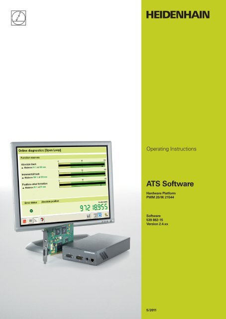
The function reserves of absolute track, incremental track and position value formation are<br />
evaluated in bar diagrams; the result is displayed in %. A drag indicator (triangle below the bar<br />
display) marks the minimum.<br />
Green range: The output signal is within the specifications.<br />
Yellow range: The output signal is outside the specifications, but no counting or calculation<br />
errors are to be expected. No alarms are generated, warnings may occur.<br />
Note<br />
The yellow range indicates: Service or maintenance recommended!<br />
Click this button to stop the recording.<br />
March 2011 Software Description 79
When you click the "Encoder parameters" button, the log display appears.<br />
Measuring range and recording period are displayed now in green color.<br />
Example: Input of encoder and machine data<br />
Note<br />
Click this button to save the data in a text file. The file location is defined<br />
in a context menu.<br />
The text file can be archived when the machine is shipped, and it can be used to describe<br />
the faults, if the encoder needs to be repaired.<br />
80 <strong>HEIDENHAIN</strong> ATS Software Operating Instructions
Example:<br />
The text file (*.txt) is saved in the program directory of the ATS software.<br />
March 2011 Software Description 81
3.5.4.2 Closed Loop function<br />
Click the Cosed Loop function.<br />
Data communication between control (TNC/NC) and encoder is picked up by a signal splitter (in<br />
the example: SA 100 Service Adapter, ID 363706-01). The encoder loop remains closed and the<br />
NC control can still traverse the machine axis.<br />
Prerequisite:<br />
"Listening in" is only possible with purely serial interfaces (EnDat 21 and 22, Fanuc, Mitsubishi,<br />
<strong>DR</strong>IVE-CLiQ). The subsequent electronics must support the diagnostic function! The diagnostic<br />
function of the subsequent electronics (TNC control) must be active!<br />
Message, if data communication fails:<br />
Message, if the test unit cannot synchronize with the data stream (diagnostic function of<br />
subsequent electronics inactive):<br />
The further procedure is similar to the open-loop measurement, see chapter “Open Loop<br />
function" on page 78.<br />
82 <strong>HEIDENHAIN</strong> ATS Software Operating Instructions
3.6 Configuration<br />
Start the ATS software.<br />
Select the "Configuration" group.<br />
In the "Configuration" group you can make the following settings:<br />
Configure hardware<br />
Language selection<br />
Manage product keys<br />
March 2011 Software Description 83
3.6.1 Configure hardware<br />
1 PCI bus number and the PCI device number of the installed test unit<br />
2 Serial number of the test unit<br />
This function scans the computer and lists the test unit hardware that was found.<br />
Confirm with OK to return to previous screen.<br />
From the list select the desired test unit.<br />
Note<br />
The serial number is required to generate a product key.<br />
84 <strong>HEIDENHAIN</strong> ATS Software Operating Instructions
3.6.2 Language selection<br />
1 Select German or English<br />
Set the operating language.<br />
Confirm with OK to return to previous screen.<br />
March 2011 Software Description 85
3.6.3 Manage product keys<br />
In addition to the function groups and functions of the ATS software (see chapter “Operating<br />
Concept" on page 19) <strong>HEIDENHAIN</strong> reserves additional special functions (e.g. for the<br />
<strong>HEIDENHAIN</strong> Service) that can be activated by product keys.<br />
Note<br />
The product key generated by <strong>HEIDENHAIN</strong> is linked to the serial number of the hardware.<br />
The special functions cannot be transferred to other hardware by means of the product key!<br />
1 Input box for product key<br />
2 Serial number of the hardware<br />
3 Display field for new optional function groups<br />
86 <strong>HEIDENHAIN</strong> ATS Software Operating Instructions
Example: Entering a product key<br />
An optional function is enabled by <strong>HEIDENHAIN</strong> Traunreut. The product key is generated and<br />
sent by e-mail.<br />
Click "Add" to activate the product key.<br />
1 Product key input field<br />
2 Serial number 14908595 (example) of the installed IK 215<br />
If further hardware is installed, the list is expanded and the active hardware is marked or can<br />
be selected.<br />
3 Names of the enabled options<br />
Click "Close" to terminate product key entry.<br />
Note<br />
The enabled function groups/functions become only visible in the ATS main menu after the<br />
encoder was selected.<br />
March 2011 Software Description 87
3.6.4 Display software version<br />
To display the installed version of the ATS software proceed as follows:<br />
88 <strong>HEIDENHAIN</strong> ATS Software Operating Instructions
3.7 Mounting Wizard for ECI/EQI<br />
Use the "Mounting" function group to check inductive motor encoders (ECI or EQI) on servo<br />
drives and to adjust them mechanically and electrically.<br />
For detailed mounting information please refer to the ECI/EQI mounting instructions and product<br />
information.<br />
Attention<br />
The encoders may only be mounted and adjusted by especially trained staff. Special tools<br />
(product key for ATS software, adjusting tools) and documentation are required to adjust the<br />
encoders.<br />
The inductive ECI/EQI series are rotary encoders for integration without integral bearing. The<br />
scanning gap between rotor and stator must be set by hand. The actual scanning gap is<br />
determined indirectly from the output voltage in the encoder. Various ambient conditions<br />
(thermal influence at max. working temperature, changes in supply voltage +/- 5 %, encoder<br />
tolerances) have an effect on the scanning gap. To ensure the optimum scanning gap,<br />
tolerance values (drive-specific lead factors, depending on the materials of the motor and<br />
the temperature range) were determined for the different motor series. The manufacturer<br />
of the servo drive enters these values in the ATS software and uses them to adjust the<br />
encoders. In the factory default setting, the ATS software works with the standard<br />
tolerances <strong>HEIDENHAIN</strong> uses in encoder production. These settings cannot be altered<br />
without the correct product key. <strong>HEIDENHAIN</strong> reserves the right to provide product keys<br />
after consultation only.<br />
An exact diagnosis of the encoder mounting is only meaningful together with the values<br />
determined for the motor. If the ECI/EQI encoders are adjusted with incorrect setting<br />
values, the servo drive may fail before the maximum operating temperature is reached, or<br />
the encoder may be destroyed because the scanning gap is too small.<br />
Note<br />
The "Mounting" function group is only active, when an inductive ECI/EQI motor encoder is<br />
connected to the ATS software. Display and functions depend on the ECI/EQI model<br />
connected and on the active product key.<br />
March 2011 Software Description 89
3.7.1 Exl Check Function<br />
Step 1: Connecting<br />
the encoder<br />
This function test is recommended for standard inductive Exl encoders for axial mounting.<br />
The function serves to check the scanning gap, the signal amplitude and the<br />
mounting quality.<br />
Note<br />
The stated tolerances are standard values.<br />
Note for inductive ExI encoders that are not prepared for axial mounting:<br />
The manufacturer of the servo motor may have altered standard tolerances (motor-specific<br />
lead factors) depending on the materials of the motor and the temperature range.<br />
Please observe the notes in "ECI/EQI mounting wizard"!<br />
After successfully connecting and mounting an inductive ECI or EQI encoder, the "ExI Check"<br />
function appears in the "Mounting" group of the ATS main menu.<br />
Double-click "ExI Check" to activate the software wizard.<br />
Note<br />
The power supply to the encoder is activated by pressing the "Next" key. This allows for<br />
convenient change of encoders (of the same ID number) in the series production of servo<br />
motors.<br />
90 <strong>HEIDENHAIN</strong> ATS Software Operating Instructions
Press the "Info" button to display the ID and SN of the encoder.<br />
The "Status" button displays errors and warnings.<br />
March 2011 Software Description 91
Step 2: Checking<br />
the scanning gap<br />
Press the button to clear errors and warnings.<br />
Click the “Next>“ button to start the 2nd step: Checking the scanning gap<br />
The display shows the current signal amplitude at the actual angle position.<br />
The "Mounting quality" check is inactive.<br />
To check the entire measuring range the encoder must cover 1 revolution (360°).<br />
92 <strong>HEIDENHAIN</strong> ATS Software Operating Instructions
In the image below the drag indicators (2 arrows) for the min/max values are visibile.<br />
Explanation of the Peak-to-peak amplitude diagram<br />
The green area represents the standard tolerance; the optimum area (green) is between<br />
80 % and 120 %.<br />
The two drag indicators mark the minimum and the maximum amplitude.<br />
The value of the min/max signal amplitude [%] is displayed below (to the left) as well as the<br />
voltage [Vpp] of the min/max amplitude of the incremental signal (below the diagram, to the<br />
right).<br />
Note<br />
The signal amplidute is derived from and influenced by the scanning gap (air gap between<br />
rotor and stator).<br />
The min/max signal amplitude of ExI encoders with EnDat interface and without incremental<br />
signals is not displayed.<br />
Red figures indicate that the tolerance was exceeded. If the tolerance range is heavily exceeded,<br />
red double arrows are displayed.<br />
DANGER<br />
When the red double arrows are displayed (e.g. 180 %), the encoder may be destroyed (no<br />
air gap between rotor and stator)!<br />
Note<br />
With display in red color the encoder is not functional.<br />
Replace the motor or encoder, or correct the mounting!<br />
Press the "Mounting quality" button to start the check.<br />
Note<br />
During the "Mounting quality" check, the check of the "Peak-to peak amplitude" is inactive.<br />
March 2011 Software Description 93
Explanation on mounting quality:<br />
The mounting quality (numerical value) must be between 90 % and 100 %. Wobble and/or<br />
misalignment of the rotor may cause the tolerance to be exceeded. In this event check the<br />
mechanical mounting! For the measurement, slowly rotate the encoder by 360° in one direction.<br />
At the lower right of the display (blue figures) you can observe the progress in [%].<br />
As soon as the progress display reaches 100 %, the mounting quality is displayed in [%].<br />
94 <strong>HEIDENHAIN</strong> ATS Software Operating Instructions
The image below shows a good test result; all parameters are within the tolerance range.<br />
Click the "Logbook" button to save the results in the log together with a comment<br />
(for the memory location refer to Info, Display).<br />
March 2011 Software Description 95
3.7.2 ExI mounting function<br />
Step 1: Connecting<br />
the encoder<br />
The ExI inspection is completed.<br />
Press the "Restart" button to check a further encoder of the same ID.<br />
Pressing "End" leads you to the ATS main menu, where you can select another check function.<br />
Double-click "EXI Mounting" to call the ECI/EQI mounting wizard.<br />
Note<br />
The ECI/EQI mounting wizard activates the encoder power only after the "Next >" button<br />
was pressed.<br />
When you click the "Info" button, the ID and the serial number of the encoder are displayed.<br />
96 <strong>HEIDENHAIN</strong> ATS Software Operating Instructions
Clicking "Status" displays the errors and warnings.<br />
Reset errors and warnings.<br />
March 2011 Software Description 97
Step 2: Adjusting<br />
the scanning gap<br />
After you have clicked the "Next" button in step 1 the window 2nd step: Adjusting the<br />
scanning gap opens.<br />
The graphics shows the signal amplitude in [%].<br />
100% represents the optimum signal amplitude with optimum scanning gap. The tolerance limit<br />
is shown as red marking line in the scaling. A red bar means that the tolerance was exceeded,<br />
a green bar indicates that the signal amplitude is within the tolerances.<br />
Note<br />
This tolerance range may vary depending on the ID of the connected encoder. The tolerance<br />
range is the standard tolerance of the factory default setting of the ECI/EQI that is used for<br />
the <strong>HEIDENHAIN</strong> testing devices; also see "Attention" on page 89.<br />
By adjusting the scanning gap mechanically (moving the graduated disk in axial direction) you<br />
must attempt to optimize the signal amplitude as closely as possible to 100 % in the tolerance<br />
range.<br />
Note<br />
Observe the product information and/or the mounting instructions of the ECI/EQI!<br />
98 <strong>HEIDENHAIN</strong> ATS Software Operating Instructions
Step 3: Checking<br />
the mounting<br />
accuracy<br />
The tolerance range (between the red lines on the scale) must be reached to continue the<br />
program; otherwise the "Next" button will not be activated.<br />
The example below shows an optimally adjusted encoder.<br />
Note<br />
A product key is required to expand the tolerance range; also see "Attention" on page 89.<br />
Clicking the "Next" button leads you to<br />
3rd step: Checking the mounting accuracy.<br />
Slowly rotate the encoder shaft in one direction until "Progress 100%" is reached.<br />
As soon as 100 % are reached, the display changes to<br />
3rd step: Measurement of the mounting accuracy completed.<br />
March 2011 Software Description 99
The tolerance range must be reached to continue the program; otherwise the "Next" button will<br />
not be activated.<br />
Note<br />
Other display versions are possible (depending on the ECI/EQI model connected.)<br />
Meaning of the symbols:<br />
The tolerance range was observed.<br />
The tolerance range was exceeded.<br />
The image below shows a summary of the measuring results including the tolerance ranges.<br />
The image below shows the result, if the mounting accuracy was not observed.<br />
The "Next" button is replaced by "Restart" to force a repetition of the mounting accuracy<br />
check (step 1).<br />
100 <strong>HEIDENHAIN</strong> ATS Software Operating Instructions
Log entry Click the "Log" button to save the results in the log.<br />
Step 4: Adjusting<br />
the encoder<br />
position<br />
In the log, click "OK" to save the file and the comment.<br />
The text file will be saved in C:\Programs\<strong>HEIDENHAIN</strong>\ATS.<br />
The file names are "ExiMountingLogFile.txt" and – for error messages –<br />
"ExiMountingErrorLogFile.txt".<br />
Clicking the "Next" button leads you to<br />
4th step: Adjusting the encoder position: Measurement is running ...<br />
With this function the encoder is aligned to the motor emf (motor commutation).<br />
Note<br />
To adjust the motor encoder of a synchronous motor, the rotor must be optimally positioned<br />
toward the stator. To make these settings (motor power supply and rotor alignment) further<br />
information is required.<br />
Please contact the motor manufacturer for this purpose.<br />
The software supports two alignment methods:<br />
1. Mechanical alignment of the encoder position<br />
March 2011 Software Description 101
The encoder is aligned manually by rotating it in the motor mating seat. Use the "Position<br />
display" function to position the encoder.<br />
2. Alignment of the encoder position via datum shift<br />
Click the "Datum shift" button to program the datum at the current angular position.<br />
When you click the "Cancel datum shift" button the active datum shift is deleted and the<br />
encoder datum reset to the <strong>HEIDENHAIN</strong> factory default setting.<br />
Note<br />
Depending on the software configuration (product key required) buttons may be inactive!<br />
If the ECI/EQI encoder does not support datum-shift programming (older encoder models), the<br />
message "Datum shift" is generated.<br />
Press "Write protection" to protect the datum shift from being overwritten.<br />
Note<br />
Once write-protection has been activated (by clicking the "Yes" button in the message<br />
window), it can only be rescinded by <strong>HEIDENHAIN</strong>.<br />
102 <strong>HEIDENHAIN</strong> ATS Software Operating Instructions
Step 5: Disconnect<br />
encoder connection<br />
Clicking the "Next" button leads you to<br />
5th step: Disconnect encoder connection.<br />
The encoder power supply is switched off and may be disconnected.<br />
Now, there are two possibilities:<br />
Clicking the "New mounting" button, takes you to the function ECI/EQI mounting,<br />
1st step: Connecting the encoder<br />
Clicking "End" directly opens the main menu.<br />
3.8 LIC 4000 and LIP 200 Mounting Wizard<br />
Note<br />
The mounting wizards for LIC 4000 and LIP 200 are described in the mounting instructions<br />
of the encoders.<br />
March 2011 Software Description 103
3.9 Supported Interfaces<br />
3.9.1 SSI, SSI programmable<br />
The software functions are basically those of the EnDat interfaces. The interface is<br />
unidirectional. Therefore, no functions are supported that write data into the encoder.<br />
(Resetting error messages, online diagnostics, datum shift, display of memory contents,<br />
etc. is not possible!)<br />
Information in the status display:<br />
Incremental status "Frequency" indicates that the input frequency of the incremental signal is<br />
exceeded.<br />
Incremental status "Amplitudes" indicates that the amplitudes of the incremental signal are<br />
exceeded or underrun.<br />
Incremental status "Transmission" indicates that data transfer is correct (CRC test).<br />
104 <strong>HEIDENHAIN</strong> ATS Software Operating Instructions
Comparison of absolute and incremental values<br />
Unlike with EnDat encoders, speed ranges or permissible tolerances are not displayed, since<br />
these they are not available.<br />
The deviation span is displayed in red color, if the difference of absolute and incremental position<br />
exceeds the absolute measuring steps per revolution. (Example: For a 13-bit encoder the display<br />
color changes to red as of 8192 LSB.)<br />
The deviation span can be set to zero.<br />
The counting direction can be changed.<br />
March 2011 Software Description 105
3.9.2 FANUC and MITSUBISHI<br />
The software functions are basically those of the EnDat interfaces.<br />
FANUC and MITSUBISHI interfaces are purely serial interfaces; incremental signals are not<br />
transferred. The interfaces are unidirectional. Therefore, no functions are supported that write<br />
data into the encoder. (Resetting error messages, display of memory contents, etc. is not<br />
possible!)<br />
Examples of displays in the status line<br />
FANUC/MITSUBISHI status "Transmission" indicates that data transfer is correct (CRC test).<br />
FANUC/MITSUBISHI status "Alarm" is a group signal to indicate that one or several error<br />
messages are set in the encoder.<br />
With the FANUC interface the status display can only be reset by switching the encoder off<br />
and on.<br />
With MITSUBISHI the ATS delete symbol can be used for resetting.<br />
106 <strong>HEIDENHAIN</strong> ATS Software Operating Instructions
3.9.3 <strong>DR</strong>IVE-CLiQ<br />
<strong>DR</strong>IVE-CLiQ is the system interface of the Sinamics drive system by SIEMENS. For more<br />
information on <strong>DR</strong>IVE-CLiQ, please contact SIEMENS. <strong>DR</strong>IVE-CLiQ is a registered trademark of<br />
the SIEMENS AG.<br />
The software functions are basically those of the EnDat interfaces. In the following, only the<br />
software functions and control elements are decscribed that differ essentially from already<br />
described functions and elements. The <strong>DR</strong>IVE-CLiQ interface is a purely serial interface;<br />
incremental signals are not transferred.<br />
Switching between position display screen and auxiliary information screen:<br />
Display position screen<br />
Display auxiliary information screen<br />
March 2011 Software Description 107
The information transferred via <strong>DR</strong>IVE-CLiQ is defined in the PROFIdrive profile (available<br />
through the Profibus user organization.)<br />
Displayed position values:<br />
XIST1: Incremental value (X actl.)<br />
XIST2: Absolute value (X actl.)<br />
Position value 2: Redundant position value of encoders that support 'Functional safety', or<br />
incremental position value for conversion EnDat 2.2 --> <strong>DR</strong>IVE-CLiQ<br />
Status information<br />
Error: Error message from connected encoder<br />
Transmission: Error in data transmission, e.g. CRC, packet loss, ...<br />
Pos. dev.: Position comparison of XIST1 with Pos2 of encoders supporting 'Functional safety'<br />
Commu. or Speed: The ATS software compares the values for the commutation angle or<br />
speed transferred from the encoder on the basis on XIST1.<br />
Auxiliary information screen:<br />
Commutation or Speed:<br />
Encoders with a <strong>DR</strong>IVE-CLiQ interface compute these values in the encoder and then transfer<br />
them to the interface.<br />
Temperature sensor external:<br />
Display of the temparture of an external temperature sensor, if supported by the encoder.<br />
(An extremely low or high value indicates that no temperature sensor is connected.)<br />
108 <strong>HEIDENHAIN</strong> ATS Software Operating Instructions
Display detailed status information:<br />
Errors:<br />
Several error groups are distinguished:<br />
Encoder error<br />
Software error<br />
Kernel error<br />
Safety error<br />
Fault value:<br />
Detailed informatin on the error. Not available for all error numbers.<br />
Status word:<br />
The encoder status is included in each cyclic telegram. Information on internal calculations<br />
(position, commutation, speed, etc.) are saved here.<br />
Safety status:<br />
Safety-related error messages<br />
March 2011 Software Description 109
Display of encoder parameters<br />
The most important parameters of the <strong>DR</strong>IVE-CLiQ interface are displayed. The information<br />
is distributed over several screens. Press the arrow keys to page through the screens.<br />
Logistic information:<br />
Node ID:<br />
Terminal identification within the <strong>DR</strong>IVE-CLiQ drive system; worldwide unique number<br />
Device type:<br />
To specify the encoder type, e.g. integrated encoder, sealed encoder,<br />
EnDat 2.2 --> <strong>DR</strong>IVE-CLiQ converter<br />
DSA ports:<br />
For <strong>HEIDENHAIN</strong> encoders, the entry value is "1" (single-ended module).<br />
Vendor:<br />
Manfacturer code<br />
Version:<br />
Version number of connected encoder<br />
Serial number:<br />
Serial number of connected encoder<br />
Index:<br />
Always assigned 0<br />
MLFB:<br />
Ordering designation of connected encoder<br />
FW version / ROM version:<br />
Version number<br />
110 <strong>HEIDENHAIN</strong> ATS Software Operating Instructions
Encoder information<br />
Display of the most important properties of the conneted encoder<br />
Example: Single-turn encoder<br />
p12000:<br />
This value identifies the supported functions and characteristics of the encoder.<br />
March 2011 Software Description 111
p10101:<br />
This parameter defines the most important properties of the encoder. With this parameter,<br />
the CU software detects, whether the connected encoder meets the expectations, i.e. matches<br />
the configuration.<br />
112 <strong>HEIDENHAIN</strong> ATS Software Operating Instructions
4 Overview of Cables and Adapters<br />
4.1 SA 100 Service Adapter (Online Diagnosis)<br />
The SA 100 Service Adapter serves to connect the PWM 20 and the IK 215 into the measuring<br />
circuit of the machine axis ("closed loop").<br />
Using the SA 100 allows for controlled traverse of the machine axis during measurement.<br />
Note<br />
Closed-loop operation with SA 100 is possible with the EnDat 02, 21 and 22, FANUC<br />
and MITSUBISHI interfaces. Moreover, the encoder and the control must support the<br />
diagnostic function.<br />
The data transfer can only be listened in (monitored)!<br />
March 2011 Overview of Cables and Adapters 113
4.2 EnDat 2.1 / 2.2 with Incremental Signals<br />
4.2.1 Measuring EnDat 2.1 interface signals without subsequent electronics<br />
114 <strong>HEIDENHAIN</strong> ATS Software Operating Instructions
4.2.2 Connecting the PWM 20/IK 215 into an EnDat / SSI Mot.Enc. measuring circuit with 25-pin D-Sub connector<br />
March 2011 Overview of Cables and Adapters 115
4.2.3 Connecting the PWM 20/IK 215 into an EnDat Pos.Enc. measuring circuit<br />
116 <strong>HEIDENHAIN</strong> ATS Software Operating Instructions
4.2.4 Connecting the PWM 20/IK 215 into an EnDat Pos.Enc. measuring circuit (NC side)<br />
with 15-pin D-Sub connector<br />
March 2011 Overview of Cables and Adapters 117
4.2.5 Connecting the PWM 20/IK 215 into an EnDat Mot.Enc. measuring circuit via an adapter connector<br />
118 <strong>HEIDENHAIN</strong> ATS Software Operating Instructions
4.3 EnDat 2.2<br />
4.3.1 Cable adapter for EnDat 2.2. interface<br />
March 2011 Overview of Cables and Adapters 119
4.3.2 Cable adapter for APE 3xx and EIB 1xx/3xx<br />
120 <strong>HEIDENHAIN</strong> ATS Software Operating Instructions
4.4 Adapter Cable for Adjusting ExI 11xx/13xx<br />
Set of 1 adapter cable,<br />
3 adapter connectors (12-pin) and<br />
3 adapter connectors (15-pin)<br />
Note<br />
Set of 3 adapter connectors<br />
(12-pin)<br />
Set of 3 adapter connectors<br />
(15-pin, new mini jacks)<br />
To ensure good contact we recommend to replace the adapter insert after approx.<br />
500 insertion/withdrawal cycles!<br />
See HEIDENHAI Mounting Instructions: ID 526 838-xx (12-pin adapter) or<br />
ID 647 671-xx (15-pin adapter) "Encoder Cable Adapter for Installation of the ExI 11xx/13xx<br />
Inductive Rotary Encoder“.<br />
March 2011 Overview of Cables and Adapters 121
4.5 FANUC<br />
4.5.1 Measuring the FANUC SERIAL interface signals<br />
122 <strong>HEIDENHAIN</strong> ATS Software Operating Instructions
4.6 MITSUBISHI<br />
4.6.1 Measuring the MITSUBISHI high speed serial interface signals<br />
March 2011 Overview of Cables and Adapters 123
4.7 SSI<br />
4.7.1 Connecting the PWM 20/IK 215 into an SSI Mot.Enc. measuring circuit via an adapter connector<br />
124 <strong>HEIDENHAIN</strong> ATS Software Operating Instructions
5 Pin Layouts<br />
5.1 Pin Layout of PWM 20<br />
5.2 Pin Layout of the IK 215<br />
X1<br />
The pin layout of PWM 20 is described in the PWM 20 instructions for installation/<br />
commissioning, ID 729905-xx (see PWM 20 basic kit).<br />
Connection of encoder X1<br />
The encoder is connected to the encoder input X1. The layout of the 15-pin D-sub connector<br />
is as follows:<br />
Spannungsversorgung<br />
Power Supply<br />
0 V Sensor Innen-<br />
0 V schirm<br />
Internal<br />
Shield<br />
Shield on housing; Up = power supply<br />
Unused pins must not be assigned!<br />
8 7 6 5 4 3 2 1<br />
15 14 13 12 11 10 9<br />
Connection for the external functions X3<br />
Inkrementalsignale<br />
Incremental Signals<br />
Absolute Positionswerte<br />
Absolute Position Values<br />
4 12 2 10 6 1 9 3 11 14 7 5 13 8 15<br />
U P Sensor<br />
U P<br />
Attention<br />
A+ A– B+ B– R+ R– DATA DATA CLOCK CLOCK<br />
The power supply of the encoder (pin 4) can be selected by software. Care must be taken<br />
that the correct supply voltage is set at the encoder, since otherwise the encoder, the IK or<br />
the computer may be damaged! Connect or disconnect the encoders only while the power<br />
supply is switched off!<br />
For external functions, a 4-pin female connection is available through which the recording of<br />
measured values can be externally controlled. The required connector can be ordered from<br />
<strong>HEIDENHAIN</strong> under the ID 282 168-01. The signals are arranged as follows (view of the<br />
connection from outside):<br />
Pin Pin layout<br />
1 Input: Latch pulse (<strong>HEIDENHAIN</strong> internal use)<br />
2 Output: Sychnronization pulse (<strong>HEIDENHAIN</strong> internal use)<br />
3 Output: MSB of position value (singleturn), serves as mounting aid for EnDat<br />
motor encoders.<br />
4 GND<br />
March 2011 Pin Layouts 125
5.3 Pin Layout of PCB Connector of EnDat 2.2 Encoder to Subsequent Electronics<br />
126 <strong>HEIDENHAIN</strong> ATS Software Operating Instructions
5.4 Pin Layout of PCB Connector of Cable Adapter (12/15-pin) D-sub (15-pin)<br />
March 2011 Pin Layouts 127
5.5 FANUC Pin Layout<br />
128 <strong>HEIDENHAIN</strong> ATS Software Operating Instructions
5.6 MITSUBISHI Pin Layout<br />
March 2011 Pin Layouts 129
130 <strong>HEIDENHAIN</strong> ATS Software Operating Instructions
6 Contacts<br />
Your <strong>HEIDENHAIN</strong> helpline<br />
The <strong>HEIDENHAIN</strong> technical helpline<br />
The <strong>HEIDENHAIN</strong> helpline in Traunreut consists of qualified, multi-lingual specialists who will<br />
support you in solving your problems.<br />
Especially if you need technical support the <strong>HEIDENHAIN</strong> helpline team can provide detailed<br />
advice and information on measuring systems, controls, and NC and PLC programming.<br />
Measuring Systems / Machine Calibration<br />
+49 (8669) 31-3104<br />
E-mail: service.ms-support@<strong>heidenhain</strong>.de<br />
NC Programming<br />
+49 (8669) 31-3103<br />
E-mail: service.nc-pgm@<strong>heidenhain</strong>.de<br />
NC Support<br />
+49 (8669) 31-3101<br />
E-mail: service.nc-support@<strong>heidenhain</strong>.de<br />
PLC Programming for TNC<br />
+49 (8669) 31-3102<br />
E-mail: service-plc@<strong>heidenhain</strong>.de<br />
Lathe Controls<br />
+49 (8669) 31-3105<br />
E-mail: service.lathe-support@<strong>heidenhain</strong>.de<br />
The <strong>HEIDENHAIN</strong> helpline for<br />
repairs, spare parts, exchange units, complaints and service contracts<br />
Technical training<br />
Domestic Team<br />
+49 (8669) 31-3121<br />
Foreign Team<br />
+49 (8669) 31-3123<br />
Complaint management, service contracts and calibration services<br />
+49 (8669) 31-3135<br />
E-mail: service.order@<strong>heidenhain</strong>.de<br />
+49 (8669) 31-2293, 31-1695<br />
Fax: +49 (8669) 31-1999<br />
E-mail: mtt@<strong>heidenhain</strong>.de<br />
March 2011 Contacts 131
132 <strong>HEIDENHAIN</strong> ATS Software Operating Instructions
<strong>DR</strong>. <strong>JOHANNES</strong> <strong>HEIDENHAIN</strong> <strong>GmbH</strong><br />
Dr.-Johannes-Heidenhain-Straße 5<br />
83301 Traunreut, Germany<br />
{ +49 8669 31-0<br />
| +49 8669 5061<br />
E-mail: info@<strong>heidenhain</strong>.de<br />
www.<strong>heidenhain</strong>.de<br />
DE <strong>HEIDENHAIN</strong> Technisches Büro Nord<br />
12681 Berlin, Deutschland<br />
{ 030 54705-240<br />
<strong>HEIDENHAIN</strong> Technisches Büro Mitte<br />
08468 Heinsdorfergrund, Deutschland<br />
{ 03765 69544<br />
<strong>HEIDENHAIN</strong> Technisches Büro West<br />
44379 Dortmund, Deutschland<br />
{ 0231 618083-0<br />
<strong>HEIDENHAIN</strong> Technisches Büro Südwest<br />
70771 Leinfelden-Echterdingen, Deutschland<br />
{ 0711 993395-0<br />
<strong>HEIDENHAIN</strong> Technisches Büro Südost<br />
83301 Traunreut, Deutschland<br />
{ 08669 31-1345<br />
AR NAKASE SRL.<br />
B1653AOX Villa Ballester, Argentina<br />
www.<strong>heidenhain</strong>.com.ar<br />
AT <strong>HEIDENHAIN</strong> Techn. Büro Österreich<br />
83301 Traunreut, Germany<br />
www.<strong>heidenhain</strong>.de<br />
AU FCR Motion Technology Pty. Ltd<br />
Laverton North 3026, Australia<br />
E-mail: vicsales@fcrmotion.com<br />
BA Bosnia and Herzegovina − SL<br />
BE <strong>HEIDENHAIN</strong> NV/SA<br />
1760 Roosdaal, Belgium<br />
www.<strong>heidenhain</strong>.be<br />
BG ESD Bulgaria Ltd.<br />
Sofi a 1172, Bulgaria<br />
www.esd.bg<br />
BR DIADUR Indústria e Comércio Ltda.<br />
04763-070 – São Paulo – SP, Brazil<br />
www.<strong>heidenhain</strong>.com.br<br />
BY Belarus<br />
GERTNER Service <strong>GmbH</strong><br />
50354 Huerth, Germany<br />
www.gertner.biz<br />
CA <strong>HEIDENHAIN</strong> CORPORATION<br />
Mississauga, OntarioL5T2N2, Canada<br />
www.<strong>heidenhain</strong>.com<br />
CH <strong>HEIDENHAIN</strong> (SCHWEIZ) AG<br />
8603 Schwerzenbach, Switzerland<br />
www.<strong>heidenhain</strong>.ch<br />
CN <strong>DR</strong>. <strong>JOHANNES</strong> <strong>HEIDENHAIN</strong><br />
(CHINA) Co., Ltd.<br />
Beijing 101312, China<br />
www.<strong>heidenhain</strong>.com.cn<br />
CZ <strong>HEIDENHAIN</strong> s.r.o.<br />
102 00 Praha 10, Czech Republic<br />
www.<strong>heidenhain</strong>.cz<br />
DK TP TEKNIK A/S<br />
2670 Greve, Denmark<br />
www.tp-gruppen.dk<br />
<br />
543 734-26 · Ver06 · 0.5 · 5/2011 · S · Printed in Germany<br />
ES FARRESA ELECTRONICA S.A.<br />
08028 Barcelona, Spain<br />
www.farresa.es<br />
FI <strong>HEIDENHAIN</strong> Scandinavia AB<br />
02770 Espoo, Finland<br />
www.<strong>heidenhain</strong>.fi<br />
FR <strong>HEIDENHAIN</strong> FRANCE sarl<br />
92310 Sèvres, France<br />
www.<strong>heidenhain</strong>.fr<br />
GB <strong>HEIDENHAIN</strong> (G.B.) Limited<br />
Burgess Hill RH15 9RD, United Kingdom<br />
www.<strong>heidenhain</strong>.co.uk<br />
GR MB Milionis Vassilis<br />
17341 Athens, Greece<br />
www.<strong>heidenhain</strong>.gr<br />
HK <strong>HEIDENHAIN</strong> LTD<br />
Kowloon, Hong Kong<br />
E-mail: sales@<strong>heidenhain</strong>.com.hk<br />
HR Croatia − SL<br />
HU <strong>HEIDENHAIN</strong> Kereskedelmi Képviselet<br />
1239 Budapest, Hungary<br />
www.<strong>heidenhain</strong>.hu<br />
ID PT Servitama Era Toolsindo<br />
Jakarta 13930, Indonesia<br />
E-mail: ptset@group.gts.co.id<br />
IL NEUMO VARGUS MARKETING LTD.<br />
Tel Aviv 61570, Israel<br />
E-mail: neumo@neumo-vargus.co.il<br />
IN <strong>HEIDENHAIN</strong> Optics & Electronics<br />
India Private Limited<br />
Chetpet, Chennai 600 031, India<br />
www.<strong>heidenhain</strong>.in<br />
IT <strong>HEIDENHAIN</strong> ITALIANA S.r.l.<br />
20128 Milano, Italy<br />
www.<strong>heidenhain</strong>.it<br />
JP <strong>HEIDENHAIN</strong> K.K.<br />
Tokyo 102-0083, Japan<br />
www.<strong>heidenhain</strong>.co.jp<br />
KR <strong>HEIDENHAIN</strong> Korea LTD.<br />
Gasan-Dong, Seoul, Korea 153-782<br />
www.<strong>heidenhain</strong>.co.kr<br />
ME Montenegro − SL<br />
MK Macedonia − BG<br />
MX <strong>HEIDENHAIN</strong> CORPORATION MEXICO<br />
20235 Aguascalientes, Ags., Mexico<br />
E-mail: info@<strong>heidenhain</strong>.com<br />
MY ISOSERVE Sdn. Bhd<br />
56100 Kuala Lumpur, Malaysia<br />
E-mail: isoserve@po.jaring.my<br />
NL <strong>HEIDENHAIN</strong> NEDERLAND B.V.<br />
6716 BM Ede, Netherlands<br />
www.<strong>heidenhain</strong>.nl<br />
NO <strong>HEIDENHAIN</strong> Scandinavia AB<br />
7300 Orkanger, Norway<br />
www.<strong>heidenhain</strong>.no<br />
Vollständige und weitere Adressen siehe www.<strong>heidenhain</strong>.de<br />
For complete and further addresses see www.<strong>heidenhain</strong>.de<br />
PH Machinebanks` Corporation<br />
Quezon City, Philippines 1113<br />
E-mail: info@machinebanks.com<br />
PL APS<br />
02-489 Warszawa, Poland<br />
www.apserwis.com.pl<br />
PT FARRESA ELECTRÓNICA, LDA.<br />
4470 - 177 Maia, Portugal<br />
www.farresa.pt<br />
RO <strong>HEIDENHAIN</strong> Reprezentant¸ă Romania<br />
Bras¸ov, 500338, Romania<br />
www.<strong>heidenhain</strong>.ro<br />
RS Serbia − BG<br />
RU OOO <strong>HEIDENHAIN</strong><br />
125315 Moscow, Russia<br />
www.<strong>heidenhain</strong>.ru<br />
SE <strong>HEIDENHAIN</strong> Scandinavia AB<br />
12739 Skärholmen, Sweden<br />
www.<strong>heidenhain</strong>.se<br />
SG <strong>HEIDENHAIN</strong> PACIFIC PTE LTD.<br />
Singapore 408593<br />
www.<strong>heidenhain</strong>.com.sg<br />
SK KOPRETINA TN s.r.o.<br />
91101 Trencin, Slovakia<br />
www.kopretina.sk<br />
SL Posredništvo <strong>HEIDENHAIN</strong><br />
NAVO d.o.o.<br />
2000 Maribor, Slovenia<br />
www.<strong>heidenhain</strong>-hubl.si<br />
TH <strong>HEIDENHAIN</strong> (THAILAND) LTD<br />
Bangkok 10250, Thailand<br />
www.<strong>heidenhain</strong>.co.th<br />
TR T&M Mühendislik San. ve Tic. LTD. S¸TI · .<br />
34728 Ümraniye-Istanbul, Turkey<br />
www.<strong>heidenhain</strong>.com.tr<br />
TW <strong>HEIDENHAIN</strong> Co., Ltd.<br />
Taichung 40768, Taiwan R.O.C.<br />
www.<strong>heidenhain</strong>.com.tw<br />
UA Gertner Service <strong>GmbH</strong> Büro Kiev<br />
01133 Kiev, Ukraine<br />
www.gertner.biz<br />
US <strong>HEIDENHAIN</strong> CORPORATION<br />
Schaumburg, IL 60173-5337, USA<br />
www.<strong>heidenhain</strong>.com<br />
VE Maquinaria Diekmann S.A.<br />
Caracas, 1040-A, Venezuela<br />
E-mail: purchase@diekmann.com.ve<br />
VN AMS Co. Ltd<br />
HCM City, Vietnam<br />
E-mail: davidgoh@amsvn.com<br />
ZA MAFEMA SALES SERVICES C.C.<br />
Midrand 1685, South Africa<br />
www.<strong>heidenhain</strong>.co.za


