Ranchers' big blast shatters copper orebody for ... - University of Utah
Ranchers' big blast shatters copper orebody for ... - University of Utah
Ranchers' big blast shatters copper orebody for ... - University of Utah

You also want an ePaper? Increase the reach of your titles
YUMPU automatically turns print PDFs into web optimized ePapers that Google loves.
HI<br />
SUBJ<br />
Mi\|G<br />
RBB<br />
I I<br />
I : !<br />
1^^<br />
H<br />
'XI<br />
•tr<br />
yy^\<br />
(^LOV\^^<br />
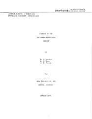
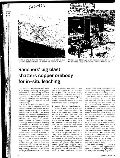
Scene ol shot is the Old Reliable mine. Lower actit is barely<br />
visible speck between two trailers at bottom <strong>of</strong> hill.<br />
<strong>Ranchers'</strong> <strong>big</strong> <strong>blast</strong><br />
<strong>shatters</strong> <strong>copper</strong> <strong>orebody</strong><br />
<strong>for</strong> in-situ leaching<br />
Tiiii iiKKa-.sr i'Ki-;-i'K()i)UC-|-ioN siior<br />
in the history <strong>of</strong> mining was Iriggoicd<br />
nil the Vth oi hist month by RiiiKhers<br />
KxpUiralion & Development Co. in an<br />
tiggicssive hid to unlock a pipe-like<br />
deposit <strong>of</strong> oxidized and sceondarily<br />
enriched <strong>copper</strong> in Arizona <strong>for</strong> low<br />
eosi recovery.<br />
In work on the Old Kcliahic project,<br />
2,OOO ions <strong>of</strong> explosive were ile-<br />
Uiii.-itcd in rutin's first attenipt to fracitiic<br />
an cniiic <strong>orebody</strong> lor <strong>copper</strong>.<br />
Principal minerals arc ch-.dcocitc.<br />
chalcopyrite. mnlachile. chalcanthiic.<br />
and ehiysocolla.<br />
The peak i>f the hill containing the<br />
ore is about 4,200 fl tibovc sea level.<br />
and the deposit begins some 100 tt<br />
below this poinl. Three ailils anil a<br />
raise in the hillside tap ihc <strong>orebody</strong><br />
(sec sectional views on Ihe third page<br />
<strong>of</strong> Ihis article). The bottom level,<br />
some 3.750 ft above sea level, is K40<br />
ft long: the niiddle level, 100 ft ;d-iovc<br />
the lower level, is 760 ft long. The<br />
upper adit is 165 fl above Ihc mldillc<br />
level and is 660 ft long.<br />
The upper workings — known •.»>.<br />
the "A" level — and approxim:itcly<br />
1.000 ft <strong>of</strong> crosscuts at right angles lo<br />
the entry wei'c ilriven hy Kop-Uan He-<br />
y.v E/MJ—April. 1072
2,000 tons <strong>of</strong> explosive were placed underground on three<br />
levels in network <strong>of</strong> headings, some old and some new.<br />
velopment Corp., a Ranchers subsidiary.<br />
The Iwo lower levels were opened<br />
during earlier mining, although<br />
Kop-Ran extended both adits and<br />
crosscuts. The lower level contains<br />
about 2,100 ft <strong>of</strong> crosscuts, while the<br />
middle level contains 3,100 ft.<br />
Planning a production program<br />
The deposit was shuttered by the<br />
4 million Ib <strong>of</strong> explosive emplaced<br />
according to a plan devised by E. 1.<br />
Du Ponit de Nemours & Co., which is<br />
providing the explosive and technical<br />
assistance on the project. (Following<br />
Ihc <strong>blast</strong>, Du Pont do Nemours acquired<br />
approximately 20% <strong>of</strong> <strong>Ranchers'</strong><br />
inlcrest in the Old Reliable <strong>for</strong><br />
S500.000, including $100,000 in explosives.)<br />
The ammonium nitrate,<br />
contained in 50-lb bags, was packed at<br />
selected points in the tunnels and<br />
crosscuts. Sand was placed ... points<br />
behind the charges to contain the<br />
energy <strong>of</strong> detonation. About 1,294,-<br />
550 Ib <strong>of</strong> explosive were placed in<br />
the bottom level; 2,103,400 Ib were<br />
stacked in the middle level and 595,-<br />
800 Ib were u.sed on the upper level.<br />
Millisecond delays were so attached<br />
to permit instantaneous explosion <strong>of</strong><br />
the uppermost level, followed by a<br />
lOO-ms delay in the detonation <strong>of</strong> the<br />
middle level, and a further 50-ms delay<br />
on the bottom 200-ft level. While<br />
early measurements indicate that the<br />
surface wns acUtuliy lifted some 40-<br />
50 ft in the air, there was substantially<br />
less flyrock developed and less<br />
surface damage incurred than expected<br />
by the engineers on the job."*-<br />
Exlensive safety tests were conduct-<br />
y^'"^ ,•<br />
•^ *••( -<br />
R?^**^'<br />
h^^ ,<br />
i<br />
r-<br />
<<br />
\:l-<br />
^y<br />
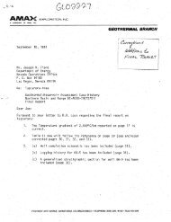
Primers and Primacord® being attached to the 50-lb bags<br />
<strong>of</strong> ANFO. Fragmentation after <strong>blast</strong> was better than expected.<br />
•^*i.<br />
^ .' :Ki' .^<br />
<br />
*•<br />
•'•t* ^<br />
»' ' ^^,<br />
\ - 1 M<br />
J... ' ,<br />
.i0t"^"'':<br />
.•f •••.,.•<br />
• --.*•.-.'Ait.':<br />
:• .--i^y: y<br />
'.1'-TSJIJ^ i*<br />
The <strong>blast</strong>, five seconds after detonation, was recorded at 2,500 ft from ground<br />
zero by camera with a 70 mm lens.<br />
ed in connection with the project, including<br />
detonation erf three test <strong>blast</strong>s<br />
ranging from 100 to 4,000 Ib <strong>of</strong> explosive.<br />
Conducted under the direction<br />
<strong>of</strong> John A. Blumc & Associates, Engineers,<br />
San Francisco — experts in<br />
the study <strong>of</strong> seismic <strong>blast</strong> effects —<br />
Ihe tests were staged to gain data on<br />
ground movement. On the basis <strong>of</strong><br />
data from these tests, Blume & Associates<br />
concluded that structural damage<br />
from the <strong>blast</strong> ut the mine would<br />
be es-sentially nil — a fact borne out<br />
by experience.<br />
The <strong>blast</strong> site is Vi mile from the<br />
nearest ranch house; 9,2 miles from<br />
Mammoth; 12 miles from the San<br />
Manuel mine; and 13.6 miles from<br />
the San Manuel smelter. The shot was<br />
detonated at a point I mile from the<br />
mine. An electrical circuit, connected<br />
by wires to <strong>blast</strong>ing caps, Primacord®,<br />
and high explosive primers placed<br />
among the bags <strong>of</strong> fertilizer, was used<br />
to initiate the <strong>blast</strong>.<br />
Observers were stationed about 3<br />
miles from the site on an unpaved<br />
road leading from the mine to Mammoth.<br />
A large area around the mine<br />
was cleared <strong>of</strong> humans, livestock, and<br />
aircraft to prevent damage or injury<br />
from flying rock.<br />
Preliminary measurement <strong>of</strong> the effects<br />
<strong>of</strong> the <strong>blast</strong> indicates that the<br />
E/MJ—April, 1972 99
y<br />
,'. 'f<br />
Wr---,<br />
\<br />
r~<br />
-T!~r-<br />
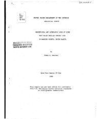
SMo View ol Old Reliable<br />
Oro Deposit<br />
[Looking Northeast)<br />
Oro<br />
O Berron Rock<br />
Tunnols<br />
Proposed Tunnol<br />
Two-dimensional view <strong>of</strong> the pipe-like <strong>orebody</strong> shows a section that looks to the<br />
northeast. The upper level was opened by Ranchers <strong>for</strong> the proiect.<br />
%.-^^y^^y^"<br />
_.^y^^ ^ "^-^ *~rx>u«<br />
^^<br />
Ov /-- S.\v-i- •"• -"i
SER<br />
MNG<br />
RCCF<br />
a ity.<br />
tions it, and f„ with small<br />
: expressions <strong>for</strong> the field<br />
•<br />
' - l ) - f •<br />
i COS 0 -1- • ••].<br />
-l) + -<br />
••]<br />
•<br />
(83)<br />
(84)<br />
(85)<br />
(86)<br />
(87)<br />
(88)<br />
Ecn derived <strong>for</strong> the conisphere<br />
in the presence<br />
.nit strength, wlien the<br />
are sufEciently near to<br />
rondary field associated<br />
ly obtained. The comc<br />
the Hertz vector funcjriniary<br />
and secondary<br />
ctor e'"'which has been<br />
ordance with equations<br />
[Dulas <strong>of</strong> the preceding<br />
dto the exact <strong>for</strong>mulas<br />
i and suitable methods<br />
deration.<br />
as (7), p. iS and (3.I, p. iSo.<br />
ysiki Bd. II, .*'09Klri5S|[<br />
,/:>'<br />
"A<br />
RADIATION FROM A CYLINDRICAL SOURCE OF FINITE LENGTH* /<br />
PATRICK AIDAN HEELAN', S.J.,t<br />
ABSTRACT<br />
This paper presents the results <strong>of</strong> a theoretical study <strong>of</strong> radiation from a cylindrical source <strong>of</strong><br />
finite lengih, the walls oi which are sulijectecl to symmetric lateral and tangential stresses. Three<br />
divergent wave systems arc generated, P, SV, and SB, and their amplitudes arc calculated in terms<br />
<strong>of</strong> the stresses operative on the walls <strong>of</strong> the "equivalent cavity." The zonal distribution <strong>of</strong> amplitude<br />
in the three wave systems is calculated, and the total amount <strong>of</strong> energy in each is estimated. It is<br />
shown that under the aciion <strong>of</strong> a lateral pressure only,an SV wave <strong>of</strong> amplitude 1.6 limes the maximum<br />
amplitude <strong>of</strong> the associated /"-wave is beamed from the source in directions making angles <strong>of</strong><br />
45" with the axis <strong>of</strong> the source.<br />
This paper is the first <strong>of</strong> a series embodying the results <strong>of</strong> a study <strong>of</strong> the nature<br />
and origin <strong>of</strong> elastic head waves.' It was thought well to begin this study by<br />
attempting to reproduce in mathematical fonn the main features <strong>of</strong> the type <strong>of</strong><br />
disturbance most frequently employed in seismic prospecting, namely, that generated<br />
by the detonation <strong>of</strong> a charge in a cylindrical shot hole. The problem we<br />
were led to consider was the eflect <strong>of</strong> transitory <strong>for</strong>ces acting upon the walls <strong>of</strong><br />
a cylindrical cavity <strong>of</strong> finite length embedded in an infinite solid medium. The<br />
results <strong>of</strong> this part <strong>of</strong> the enquiry are presented in this paper.<br />
When energy is imparted to the ground by an explosion, some is converted<br />
inlo a radiating stress-strain iield and some is utilized in producing local de<strong>for</strong>mations<br />
<strong>of</strong> a permanent character. The precise mechanism by which energy is transmitted<br />
to the ground is not clear. Considerable research has been done on this<br />
type <strong>of</strong> problem by United Slates /Vrmy and Navy engineers, but the results <strong>of</strong><br />
the research are not yet available to the public. The energy carrier, however,<br />
seems to be a shock wave which travels through the medium with supersonic<br />
speed, exepending its energy in breaking and crushing the surrounding rock,<br />
and gradually diminishing in intensity through diffusion over an ever broadening<br />
wave front. When the stresses in the expanding wave no longer exceed the<br />
strength <strong>of</strong> the medium, the shock wave.has become an elastic wave and from<br />
there on is propagated according lo the well-known laws <strong>of</strong> clastic wave theory.<br />
How the total energy imparted to the medium by a purely elastic disturbance is<br />
partitioned between a field <strong>of</strong> permanent de<strong>for</strong>mation and a radiating field <strong>of</strong><br />
<strong>for</strong>ce has been investigated <strong>for</strong> certain simple sources by Kawasumi and Yosliiyama,<br />
Sezawa, and Kanai. Sezawa- concluded that not more than half <strong>of</strong> the<br />
* Manuscript received by the Edilor October 3, 1952.<br />
t St. Stanislaus College, Tullamorc, OlTaly, Ireland.<br />
' This study w-as part <strong>of</strong> a doctoral prograni undertaken by the author under the direction <strong>of</strong> the<br />
Reverend James U. Macelwane, S.J., at Saint Louis <strong>University</strong> in 1052.<br />
' K. Sezawa, "i-Ilaslic Waves I'nxluceil by .\pplying a Statical Force to a Body or by Releasing<br />
It from a Hody," Bull. Eiirlli. His. Insl., Tokyo, i j, (1935), 740-74.S; "On the Relation between Seismic<br />
Origins and Radiated Waves,'' ibid., 14, (1936), 149-154; K. Sezawa and K. Kanai, "Elastic<br />
Waves Formed by Local Stress (.'haiiges <strong>of</strong> DilTerent Rapidities," ibiil., 10-17,<br />
68s<br />
iS?§T|ITE<br />
'•T^^^^iP^mmi^^m^^i^'^^^^i^' r^^'T-r^^f^!' ???=;tsgw,Hy\!^*fcifl3
:,-l^t'.llkv;-J.i.-.««J-:,--£teV.i^^Sl:l-^f^.^,c.-4,j;,.i-U.->...a;-^.L-.l--.L.Uri,VB^'.'i-.'£-..-^--'.-.--.",^.-.-.^nli. ti.MaaJ-.LJ.-.i-e»&':LAWi^ ^ ^ji^Bii ttst.-rtriiiik-J^x'it<br />
686<br />
t^^^''jijw%!gj!s»-
• -.,,jll^(^^'::jfe;^^^jjgy^^.:w^.L^^VI.;^^<br />
bl only when the<br />
<strong>of</strong> sources have<br />
this paper, with<br />
hole, the source<br />
n<strong>of</strong> co-ordinates<br />
his cylinder are<br />
axis, uni<strong>for</strong>m in<br />
oints, and finite<br />
rdinates (r, 0, z),<br />
(la)<br />
. . (lb)<br />
(ic)<br />
another.<br />
t the z-axis at<br />
<strong>of</strong> three wave-<br />
3Si<br />
• (2)<br />
re the compog<br />
respectively.<br />
functions, are<br />
(3a)<br />
(3b)<br />
(3C)<br />
ake the <strong>for</strong>m,<br />
'locity. The con-<br />
RADIATION FROM A CYLINDRICAL SOURCE OF FINITE LENGTH '" 687<br />
rr<br />
rz<br />
FIG. I. Source <strong>of</strong> disturbance.<br />
d /5$o /d^a a=0o\ a=0o><br />
= XV'#o+ 2M— ,<br />
dr \ dr drdz /<br />
= M—(2 -hV'0o- 2-—),<br />
dr\ dz dz^ }<br />
zz = XV^^o -f- 2/i —( -1- V^Go<br />
dz \ dz dz^<br />
^ /d-xo I 3xo\<br />
"•'y-Ty<br />
zO = ll d'xo<br />
drdz<br />
it'J'^f.t)<br />
It is now assumed that *o, ©o and xo can be expressed as the real parts <strong>of</strong>'<br />
the following integrals,<br />
$0 = r e'*»''t//fe r/o(
if<br />
jl<br />
1)<br />
I'<br />
•i<br />
1'<br />
• ^<br />
- 1 •»<br />
••1<br />
fflte^^^m>vt>i^a»f^ ^^.^.feto^tafea^si,^^<br />
688 PA THICK AIDAN HEELAN<br />
where kV = liv, Z7o"' is the Hankel function <strong>of</strong> the first kind and zero//* order,'<br />
and C is a loop from «t about —// and —k, excluding the origin and such that<br />
arg.o- = arg.(CT' — ;fe-)"^ = arg.((r- —//-)"-= 5r/2 initially.' The integrands in equations<br />
5 are determined by the conditions at the source and by Sommerfeld's<br />
conditions' which require that "I^o, ©o and xo represent divergent wave systems<br />
which are bounded at infinity.<br />
Determination <strong>of</strong> fo{a, r), gii{a, r) and rjo{a, r).—The boundary conditions (i)<br />
at the source can be expressed in another way, utilizing the contour integral.<br />
(rsinh/(
7-k'-TJi-'i 11-^1 e''ff-^irF-1 r"^i[<br />
ind and zero/// order,-^<br />
e origin and such that 1<br />
: integrands in equa- |<br />
and by Sommerfeld's<br />
ivergent wave systems<br />
lundary conditions (i)<br />
the contour integral,<br />
r,<br />
>^<br />
), at the source, is,<br />
-''y'^dcr.<br />
Fourier integral,<br />
jllowing;<br />
'{•'-*•)"'(/(fu)<br />
- 2q,{k)n^{c^ - r-)"^f [//o
iM^:^!&k~iJi^''' a^.A£iC,^„^i.„„.;" -',-.-..:,..-<br />
690<br />
Wo=^<br />
yk)'Ac<br />
Sirnitj'- - //')»'*<br />
P^TR/CA' AIDAN UEELAN<br />
where A = volume <strong>of</strong> the.sourec = 27r3*/,-and .^4 -arcri <strong>of</strong> vertiizal \valls-<strong>of</strong> source<br />
= 47ra/r<br />
The actual particle displacements, in the..radiated field are obtained by inserting<br />
(s) into (3) and substituting tLhe-values.<strong>of</strong>/o, Jo and «<strong>of</strong>rom (7) or, at large<br />
distances from the. source, from (8), Thus the radial component becomes<br />
« f o'/o///')'((7r)e't''-**>"'^ff-H fa-V- /i^}"^S<strong>of</strong>fit"Me'\ d-<br />
u —<br />
•A.irit.VR \ \ ' V<br />
4ii^ sin 0 cos 0<br />
4irjuF'i; ^<br />
A-sin 0 cos' 0 (/<br />
•2-trix'i)R<br />
A sin 0 cos ^<br />
(Sc)<br />
,^1TliR (-7)- (10)<br />
•C/. E. T. Gopson, Inlrodmlion tp-llieTbeor.y-<strong>of</strong> Fmiclipiis <strong>of</strong>a Complex 'Variable {London; Oxf,<br />
Univ. Press, r93"5), pp.,330 ff. • •<br />
where<br />
and<br />
RA DIA TIG.<br />
d -<br />
It. .<br />
In a similar ma<br />
On inspection, thes<br />
systems, a P-wave<br />
polarized shear wa'<br />
vsH, o), both <strong>of</strong> whi<br />
Putting<br />
the P-wave becomes<br />
'"^1= P''(^)<br />
- ''t'pJ L R<br />
the^r-wave,<br />
•«sv1 VFiiit)<br />
Lw,FrJ L R<br />
the 5//-wave,<br />
The coefficients {i<br />
lar variation <strong>of</strong> the air<br />
0,,are graphed in Figii
(8c)<br />
il walls <strong>of</strong> source<br />
; obtained by inom<br />
(7) or, at large<br />
t becomes<br />
)(:^^!'.|^^^jjiMl^^^<br />
-•I
i'<br />
-3<br />
692 PATRICK AI DAN HEELAN<br />
FIC. 2. 'Variation <strong>of</strong> P and SV amplitudes with 0, when the source is subjected to a pressure<br />
p(l) only. Radii in the figure are proportional to F)(,
•ce is subjected to a pressure<br />
), and to Fi(.(t>) (in the case <strong>of</strong><br />
f *,•/ is the stress tensor<br />
iisplacement,, then, the<br />
unit vector /;,• is<br />
I throughout the durakvaves<br />
is obtained. For<br />
Ep' due to the lateral<br />
e shearing .stress qiO-<br />
,g^^,gi^^;^f^''g^j«,dajtSiMfciiiiu^<br />
RADIATION FROM A CYLINDRICAL SOURCE OF FINITE LENGTH 693<br />
FIC. 3. Variation <strong>of</strong> P and SV amplitudes with 0, when the source is subjected to shearing stress<br />
9(0 only. Radii arc proportional to Ci()-, cf. equations lae and 13c.<br />
and<br />
Ep' ^ A=P=<br />
ATTHV^ \S<br />
Ep" = A^-QHV i2TrnV\<br />
/2V^ V 2 \<br />
'^iisi'-^-^^^m'i^'^i^' ,«^u.iwu..,v,.»,.., iwg?.*^g?^?g?H^M»a*Ma^^»p
'^ '<br />
ill;<br />
1<br />
h<br />
•S<br />
^'!g«i3Jaai.*£«»Atet..i«;te>,.i.-,--/K^£<br />
694 PATRICK AIDAN HEELAN<br />
FIG. S. />(0 =PO exp.(-ir/»//o').<br />
^= f^" [/'(/) ]v/,<br />
- *'-«o .<br />
Q= f 'WiDUL<br />
For 5K, the total energy Esv is similarly constituted, Esv' being due to the<br />
lateral pressure pit) at the source, and E..,y" to the shearing stress qit). Thus,<br />
where<br />
and<br />
Esv = Esv' -\- Esv"<br />
Esv' = 2A2pyi5fl-/it,»,<br />
-fc'sK" = /l='(2V6ir/.c.<br />
The energy <strong>of</strong> SH is due entirely to the horizontal shearing stress j(/) acting<br />
at the source, and is,<br />
mr^iUiliiifailSISmm^' •'4*i9i«tWS*HM! ••~ a!J!^!AS1B.y4}Wi^j^jtjt)!jga^;:-i^^^<br />
;.i,.«*irf>-SSife«fci akv^WiSi' *tffr?»fliii
Esv' being" due to the<br />
; stress ?(/). Thus,<br />
iring stress j(/) acting<br />
j,^ga(.VUjjj!ti>SFJiaB?i«Jj«^J3<br />
„-.u,«»^k£.;-.--,-v..^ __£jj-;-rii>v-'^-i^^'^^^^<br />
1<br />
^...<br />
where<br />
RADIATION FROM A CYLINDRICAL SOURCE OF FINITE LENGTH 695<br />
Esu = ^'Sy67r^tv\ y ' (^ ^\<br />
= f'''[s"{t)]'dt.<br />
•/ -00<br />
DISCUSSION OF RESULTS<br />
We have tried to reproduce, in mathematical <strong>for</strong>m, the disturbance generated<br />
by the detonation <strong>of</strong> a charge in a cylindrical shot hole. The quantities a and I are<br />
not the physical dimensions <strong>of</strong> the bore hole in which the charge is detonated.<br />
Conditions in the immediate neighborhood <strong>of</strong> the shot hole are such that the<br />
assumptions upon which our work is founded, in particular the assumption <strong>of</strong><br />
infinitesimal strain, are not verified in this domain. These quantities correspond<br />
rather to the dimensions <strong>of</strong> Sharpe's "equivalent cavity."' This is the smallest<br />
surface about the shot hole beyond which the medium is "perfectly elastic" to<br />
the disturbance. Morris'" says that it is "determined by the position at which no<br />
further work is done on the medium by the shock wave." The <strong>for</strong>m <strong>of</strong> the "equivalent<br />
cavity" determines to a large extent the characteristics <strong>of</strong> the elastic waves<br />
generated by the source.<br />
•The partition <strong>of</strong> energy between the dilatational and shear waves generated<br />
by the application <strong>of</strong> a lateral pressure pit) to the walls <strong>of</strong> a cylindrical source is a<br />
problern <strong>of</strong> special interest as it represents the ideal case <strong>of</strong> a charge detonated in<br />
a shot hole. In this case.<br />
Ep' ' _ x^iv^ 157* 5\<br />
Es\<br />
K'\2F M 2/<br />
For a Poisson solid, (r4) implies that approximately 60 percent <strong>of</strong> the energy<br />
goes into SV and only 40 percent into P. Moreover SV is beamed in directions<br />
making angles <strong>of</strong> 45° with the axis <strong>of</strong> the source (see Fig. 2), with maximum amplitude<br />
1.6 times the maximum amplitude <strong>of</strong> P.<br />
These results at first sight cause some surprise. It has <strong>of</strong>ten been said that<br />
artificial disturbances generate little shear energy." .-Actually this is not always<br />
the case. Wiechert, Brockamp, Wiilcken, Jeffreys and others have reported shear<br />
waves <strong>of</strong> large amplitude present in the seismograms <strong>of</strong> large explosions. Seismograms<br />
<strong>of</strong> local <strong>blast</strong>s occurring within, say, 20 km <strong>of</strong> Florissant <strong>of</strong>ten contain a<br />
powerful SV phase. Whether this phase is <strong>of</strong> primary origin, originating at the<br />
actual source, or <strong>of</strong> secondary origin, due to a change in type somewhere along<br />
• J. A. Sharpe, "The Protluction <strong>of</strong> El-.islic Waves liy Explosion Pressures: i. Theory and Empirical<br />
Field Obser\ations," Geophysics VII (1942), 14.^-154.<br />
" G. Morris, "Sonic Considerations <strong>of</strong> the Mechanism <strong>of</strong> the Generation <strong>of</strong> Seismic Waves by<br />
l'"..xplosives," Geophysics, XV (1950), 61-69.<br />
" Cf. TS. Jeffreys, Reports on Progress in Physics, 10 (1944-1945), 79.<br />
i;ya
\ -'<br />
696 PATRICK AIDAN HEELAN<br />
^^^siM^^^SSik^MS<br />
the trajectory <strong>of</strong> the ray, is still not clear. The theory given in this paper indicates,<br />
at any rate, that this SV phase is actually <strong>of</strong> primary origin. Moreover the<br />
theory shows that a characteristic <strong>of</strong> this wave is that it is channelled in certain<br />
directions. The low intensity <strong>of</strong> shear waves on some <strong>blast</strong> records may be merely<br />
indicative that the seismometer is located outside the range at which the SVcone<br />
<strong>of</strong> energy reaches the surface. Little use so far has been made <strong>of</strong> sliear waves<br />
in seismic prospecting, as their late arrivals are usually obscured by much background<br />
noise. Should it be practicable, however, to use these waves, the existence<br />
<strong>of</strong> the beamed 5K-wave might prove to be <strong>of</strong> some importance.<br />
The absolute magnitude <strong>of</strong> the total energy radiated by the action <strong>of</strong> the<br />
pressure />(/) is, as we have seen, proportional to<br />
J _oo<br />
The total amount <strong>of</strong> radiated energy depends in this case upon the double rate <strong>of</strong><br />
change <strong>of</strong> the applied stress. Assuming that<br />
then<br />
and thus,<br />
Pit) = Po exp i-i^iyi^) (see Fig. 5),<br />
Ep' = 3rA=P,<br />
2"VI'"^<br />
P = 3Po7r':2->/o-';<br />
where A = volume <strong>of</strong> the "equivalent cavity," Pp = maximuni pressure at the<br />
source.<br />
Ep', Esv' and ESH, being proportional to /»"' increase very rapidly with decrease<br />
in the duration <strong>of</strong> the impulse. Moreover, the total energy radiated by<br />
such a source is proportional to the product APQ. The observations <strong>of</strong> Sharpe" and<br />
Morris'^ help to confirm these conclusions.<br />
'• Op. cit.<br />
«'?t^^^^^''*%P^^i!l ^B^PJji^^ I >j^giqB,)pBfcs iy,Ujti^<br />
Recent national and i:<br />
The probable removal <strong>of</strong> m<br />
(rce economy is about to I<br />
the first time in several d<<br />
In our part <strong>of</strong> the wort<br />
and say what w-e please—1<br />
carry us where it will. Fn<br />
We have the immeasurab<br />
expansion based on a free<br />
We dare not take all<br />
fully lo live. Our preoccu|<br />
licipalion as good citizens<br />
.•\re we truly using 011<br />
vantage <strong>of</strong> the unlimited<br />
Ever},- so <strong>of</strong>ten it pay:<br />
and dig in <strong>for</strong> a new star<br />
tion. The very fact that<br />
may tend to make us COD<br />
As oil-finders we are<br />
do we live in a free socie<br />
freedom to cvercise our i<br />
Decentralization, de<br />
new watch-words <strong>of</strong> the<br />
paign, must catch this s]<br />
The techniques, the<br />
dominate our current eff'<br />
the tempo <strong>for</strong> our presci<br />
past and free his latent<br />
The freedom we enj<<br />
<strong>of</strong> our industr>'. It is, ii<br />
potentialities <strong>for</strong> frcedor<br />
throw <strong>of</strong>f our self-impos<br />
* Printed as guest e<br />
t General Petroleui<br />
Geophysicists. Now -wit<br />
' ^''^mf^sfiomssmmmsBBmm
SUBJ<br />
IMNG<br />
RCD<br />
UNIVERSITY OF UTAH<br />
RESEARCH INSTITUTE<br />
EARTH SCIENCE LAB.<br />
Methods <strong>of</strong> recovering low-cost <strong>copper</strong> htj precipitation from<br />
dilute solutions is lucidly revieived. Alternatices to cementing<br />
on scrap, a high-cost practice, are studied. The author<br />
also examines work which has been per<strong>for</strong>med in other<br />
chemical methods <strong>of</strong> precipitating <strong>copper</strong> from solutions.<br />
Certain health hazards are pointed out and a system, <strong>of</strong><br />
automatic control is proposed.<br />
THE RECOVERY OF COPPER FROM DILUTE<br />
Treating <strong>copper</strong> ores by heap-leaching and similar<br />
hydrometallurgical means is a time-honored<br />
practice,' which was well known even in the 19th<br />
century. Later the method lost ground to better ore<br />
dressing processes, particularly selective flotation.<br />
More recently there has been a distinct reversion<br />
to leaching techniques, particularly <strong>for</strong> scavenging<br />
operations in old mining stopes, in connection with<br />
• LPF systems, irrigation <strong>of</strong> tailings dumps and similar<br />
situations. These hydrometallurgical techniques<br />
will gain further ground because processing is simple<br />
and permits better extraction <strong>of</strong> <strong>copper</strong>, particularly<br />
from low-grade or partly oxidized ores.<br />
In the lixiviation <strong>of</strong> primary ores at some major<br />
operations, <strong>copper</strong>- bearing liquors may undergo recirculation<br />
in heap-leaching arrangements or the<br />
ores may be subjected to systematic percolation<br />
treatment. The liquors resulting from this source<br />
usually are quite strong (above 10 gpl <strong>copper</strong>) and<br />
<strong>copper</strong> would normally be reclaimed by electrowinning<br />
or cementation. These processes fall outside<br />
the scope <strong>of</strong> this paper which is concerned<br />
with recovery <strong>of</strong> <strong>copper</strong> from weak liquors containing<br />
from 0.1 to about 3 gpl <strong>copper</strong>.<br />
Total production from such dilute process streams<br />
is probably less than 100,000 tons <strong>of</strong> <strong>copper</strong> per<br />
year and so it is not a major factor in world <strong>copper</strong><br />
siipplies. On the other hand, this source <strong>of</strong> the red<br />
metal is more important to the cppper mining industry<br />
than production statistics would indicate because<br />
it is low cost <strong>copper</strong> with a high pr<strong>of</strong>it margin.<br />
J. S, JACOBI, Member <strong>of</strong> AIME, is Director <strong>of</strong> Research, Cerro<br />
de Posco Corp,, Lo Oroyo, Peru, Article is abridged version <strong>of</strong><br />
paper presented at AIME Annual Meeting, Dallas, 1963, Entire<br />
paper will be published in Proceedittgs <strong>of</strong> Interttotional Sytrtposium<br />
ott Unit Processes itt HytlromeiollurgY to be issued in early 1964,<br />
All weak cupriferous streams whether from natural-mine<br />
waters, artificial irrigation <strong>of</strong> old workings<br />
or run-<strong>of</strong>fs from tailings dtunps, have common<br />
characteristics. They are usually quite acid and<br />
contain little <strong>copper</strong> but much iron. Despite such<br />
unprepossessing appearances they can be reclaimed<br />
<strong>for</strong> less than 10(5 per.lb. The reason is that residual<br />
<strong>copper</strong> in old stopes, tailings, etc., carries no book<br />
value and any metal thus available, more or less<br />
<strong>for</strong>tiutously, is to be had cheaply. In consequence,<br />
the <strong>copper</strong> mining industry obtains a gross return<br />
from such scavenging operations which, on a worldwide<br />
basis, must be <strong>of</strong> the order $20 million annually.<br />
This figure is subject to the usual deductions<br />
<strong>for</strong> refining and realization charges, overheads,<br />
taxes, etc. Approximately, each gallon per minute<br />
<strong>of</strong> an effluent carrying 1 gpl Cu is worth $1000<br />
per year.<br />
PRECIPITATION ON SCRAP IRON<br />
This is the most common method <strong>of</strong> treating mine<br />
waters. The main.parameters governing plant design<br />
are: contact time, water velocity and launder<br />
volume per unit <strong>of</strong> <strong>copper</strong> reclaimed. These <strong>of</strong><br />
course are interdependent with the <strong>copper</strong> content<br />
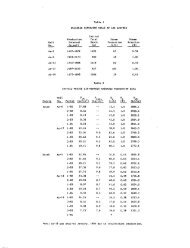
<strong>of</strong> the process stream. Table 1 vindicates how the<br />
design factors vary considerably from plant to plant,<br />
as does the <strong>copper</strong> content <strong>of</strong> the head and tailing<br />
waters. Within certain limits, the prime consideration<br />
is volume <strong>of</strong> launder space in relation to cement<br />
<strong>copper</strong> production, or the size <strong>of</strong> "a given plant<br />
is governed less by the water volume to be handled<br />
than by the <strong>copper</strong> content <strong>of</strong> these waters. From<br />
the point <strong>of</strong> view <strong>of</strong> turbulence and adequate diffusion,<br />
a relatively high water velocity is preferable,<br />
provided that contact time does not suflfer.<br />
Centralized precipitation plants-on-surface fall,<br />
into two groups, the zig-zag launder and the sti:aight<br />
56_MINING ENGINEERING, SEPTEMBER 1963 SOCIETY OF
w<br />
by J. S. JACOBI<br />
PROCESS STREAMS<br />
line arrangement. The zig-zag arrangement is more<br />
compact and somewhat cheaper to operate but is<br />
less flexible <strong>for</strong> adding to the water volume. In<br />
this case contact time may be maintained by adding<br />
zig-zag launders to the system, but velocity will be<br />
raised in proportion and may lead to difficulty with<br />
suitable falls. Inadequate slopes are difficult to correct<br />
in an existing plant. The straight line launder<br />
lends itself to the addition <strong>of</strong> parallel units, if scrap<br />
iron is fed by mobile cranes with clam shells or<br />
electromagnets instead <strong>of</strong> overhead gantrys <strong>for</strong>merly<br />
in vogue.<br />
At Cerro de Pasco, <strong>copper</strong> reclamation from mine<br />
water is still .underground in, a channel along a<br />
main drift on the 1400 ft level. All pregnant waters<br />
are pumped from lower levels or gravitate from<br />
higher levels to this ditch which is about 1200 ft<br />
long. By centralizing activities, considerable labor<br />
savings have resulted and operations have been<br />
streamlined at practically no capital cost. Scrap iron<br />
still has to be taken underground but is easily<br />
dumped into position from ore cars. Mine waters<br />
are segregated and the water volume treated cut<br />
from 1800 gpm to 500 gpm. However, segregation<br />
is not perfect and "barren" waters are recombined<br />
with the tailing water and pumped to the surface<br />
by a single system <strong>for</strong> scavenging treatment in surface<br />
lavmders. This arrangement, although satisfactory,<br />
is not the final answer and a new surface<br />
precipitation plant is under study.<br />
Another system which has been studied but not<br />
put into practice is the use <strong>of</strong> an old mine shaft<br />
into which scrap iron is dumped. Laboratory testing<br />
showed that adequate stripping <strong>of</strong> the mine<br />
waters can be achieved by a single pass through a<br />
packed depth <strong>of</strong> 65 ft which was calculated to give<br />
a contact time <strong>of</strong> 45-50 min. Percolating mine water<br />
at 10 gpm per sq ft <strong>of</strong> cross-sectional area, the <strong>copper</strong><br />
content was reduced from 2.4 to 0.01 gpl. Surprisingly<br />
no ill effects were observed from aeration<br />
which <strong>of</strong> course cannot be avoided under these conditions.<br />
A vertical column is good in theory but<br />
compaction <strong>of</strong> the scrap iron could lead to inadequate<br />
liquor distribution.<br />
SCRAP IRON CONSUMPTION •<br />
Although scrap iron is almost universally used<br />
<strong>for</strong> cementing <strong>copper</strong>, it is expensive, particularly<br />
in isolated localities. Most light sheet metal <strong>of</strong>f-cuts<br />
are lacquered and have to be burned, shredded or<br />
otherwise prepared which adds to the expense. In<br />
the future light scrap supplies may be contaminated<br />
with aluminum cans, satisfactory <strong>for</strong> cementation<br />
but a serious toxic risk. Mine scrap, such as old castings<br />
or rail, have small surface or high carbon content<br />
and are not effective precipitants; they can be<br />
used gradually in the first launder sections where<br />
the acidity is high. The best scrap must go to the<br />
final or scavenging sections. Even so, scrap iron<br />
alone cannot reduce the <strong>copper</strong> content <strong>of</strong> the tailing<br />
to less than 60 mgpl Cu without resorting to<br />
artificial agitation.<br />
Scrap iron consumption varies mostly with ferric<br />
iron content <strong>of</strong> the pregnant waters because it must<br />
be reduced to the ferrous state and much free acid<br />
must be killed be<strong>for</strong>e precipitation <strong>of</strong> <strong>copper</strong> can<br />
take place. In practice a good working figure <strong>for</strong><br />
effluents containing ferric iron is. 2 lb scrap per<br />
lb Cu precipitated. Pyrrhotite has been found to be<br />
an effective reducing agent <strong>for</strong> ferric iron, and pilot<br />
tests have confirmed this. By leaving pregnant mine<br />
waters in contact with lump pyrrhotite ore <strong>for</strong> three<br />
hours all iron was reduced to the bivalent condition<br />
and scrap iron consumption was cut down to 1.25<br />
lb scrap per lb <strong>of</strong> <strong>copper</strong> precipitate.* The reaction<br />
is:<br />
FerSs -f 32 H2O -|- 31 Fez (804)3<br />
-• 69 FeS04 -f 32 H2SO4<br />
According to the above reaction 1 lb <strong>of</strong> pyrrhotite<br />
would have the same reducing power as 2.68 lb<br />
<strong>of</strong> scrap iron. In actual fact it was found that 1 lb<br />
<strong>of</strong> pyrrhotite will replace from 1.5 to 2.2 lb <strong>of</strong> scrap<br />
depending on the grade <strong>of</strong> pyrrhotite! used.<br />
Pyrite did not have the same reducing effect as<br />
pyrrhotite, even with air rigidly excluded. Yet from<br />
time to time a curious phenomenon has occurred<br />
whereby metallic <strong>copper</strong> seems to have precipitated<br />
on truly pyritic mineral in the mine but such occurrences<br />
are rare and it has been impossible to<br />
reproduce them in the laboratory. Nor is such a<br />
reaction thermodynamically probable. The coating<br />
<strong>of</strong> pyrite or sphalerite by <strong>copper</strong> sulfide is a contingency<br />
thaf one'iriiist always bear in mind" when<br />
irrigating old stopes with near neutral waters containing<br />
dissolved <strong>copper</strong>;<br />
Roaster gases containing sulfur dioxide can be<br />
used <strong>for</strong> conditioning mine waters. This can be done<br />
<strong>for</strong> instance in a normal gas scrubber system. Incidentally<br />
the irrigation <strong>of</strong> roaster gases with oxidized<br />
mine waters may help to overcome, at least<br />
partially, a nuisance from sulfur dioxide emissions.<br />
Small scale experiments,^ contacting actual mine<br />
waters and roaster gases containing about 9% SO2<br />
in stoichiometric proportions, showed that most <strong>of</strong><br />
the sulfur dioxide can be absorbed and most <strong>of</strong> the<br />
ferric iron reduced in a simple scrubber system <strong>of</strong> -<br />
modest proportions. Again the net effect in mine<br />
MINING ENGINEERS SEPTEMBER 1963, MINING ENGINEERING—57<br />
I I
Launder system<br />
Mine water flow, gpm<br />
Copper content, gpl Cu<br />
head waters<br />
Tailings waters;.<br />
Copper recovered In<br />
launders, %<br />
Daily production, lb fine<br />
<strong>copper</strong><br />
Number <strong>of</strong>. launders<br />
Length per launder, £t<br />
Cross-section alx)ve grid<br />
Width, ft<br />
Depth, ft<br />
Total effect launder vol, ..<br />
cu ft<br />
Launder vol to Cu produced,<br />
cu ft per lb<br />
per day -<br />
Velocity <strong>of</strong> mine water,<br />
fpm<br />
Contact time, min<br />
Plant A<br />
Zigzag<br />
2.500<br />
0.85<br />
0.022<br />
97.4<br />
24,600<br />
16 double<br />
40<br />
12/3<br />
S<br />
64,000<br />
2.6<br />
6.7<br />
192<br />
A: Inspiration Copper.'<br />
B: Ohio Copper^ (Bingham C^anyon).<br />
C: Anaconda, Butte.><br />
Toble 1 . Comparison <strong>of</strong> Several Copper Precipitotion Plants<br />
Plant B<br />
straight ine<br />
840<br />
2.04<br />
0.06<br />
97.3<br />
20,000<br />
200 single .<br />
16<br />
2 2/3<br />
2 2/3<br />
21,362<br />
1.1<br />
32.0<br />
50<br />
Plant C<br />
Straight line<br />
5.000<br />
- 0.31<br />
0.016<br />
95<br />
18,000<br />
20 single<br />
100<br />
10<br />
3<br />
54,000 .<br />
3.0<br />
6.5<br />
78<br />
Plant D<br />
Zigzag<br />
590<br />
2.41<br />
o.oe-?<br />
97.2<br />
17,100<br />
3 6 comp<br />
64<br />
10<br />
6<br />
69,120<br />
4.0<br />
1.3<br />
875<br />
D: Andes Copper.*<br />
E: Cananea.*<br />
F: Small instn in South America.<br />
waters treatment is a marked lowering in scrap<br />
iron consumption.<br />
re2(S04)3(aq) -I- SO,(g) -1- 2 HzOO)<br />
^ 2 FeSOiCaq) -I-2 H2S04(aq)<br />
F — 28.9 kcal per Mol<br />
A relatively low acidity assists the reaction, while<br />
low oxygen concentration is essential; otherwise the<br />
"autoxidation" reaction takes over:<br />
SOo(g) -^ 2FeS04(aq) -I- OjCg) Fe2(S04)3(aq)<br />
- 68.9 kcal per Mol<br />
The latter reaction can, <strong>of</strong> course, be helpful <strong>for</strong><br />
leaching but it is quite detrimental in the cementation<br />
stage,<br />
SPONGE IRON AND SIMILAR PRECIPITANTS<br />
Indications are that-use <strong>of</strong> scrap iron will grad-.<br />
ually decline in favor <strong>of</strong> sponge iron. Sponge iron<br />
is being used on an increasing scale <strong>for</strong> leach-precipitation-flotation<br />
systems and its use has contributed<br />
markedly to the extraction <strong>of</strong> <strong>copper</strong> from<br />
partly oxidized ores. In LPF plants the sponge is<br />
used in the finely divicied state, <strong>of</strong>ten after magnetic<br />
up-grading. A similar technique couM be<br />
applied to mine waters but it would mean contacting<br />
in agitation vats which is relatively costly. Assume<br />
an effluent containing 1 gpl Cu at a rate <strong>of</strong><br />
2000 gpm. "With a contacting time <strong>of</strong> 30 min a total<br />
agitator volume <strong>of</strong> 60,000 gal is necessary. Counter<br />
current contacting being impractical, precipitant<br />
must be added to each agitator in series; there<br />
should be some excess sponge in the system in the<br />
final agitator to avoid any re-solution <strong>of</strong> <strong>copper</strong>.<br />
A pelletized sponge can be made by roasting<br />
pyrite pellets in a fluidized bed (the roaster gases<br />
can be used <strong>for</strong> pre-conditioning mine waters)<br />
after which the pyrite cinders, still in the pelletized<br />
<strong>for</strong>m, are converted to sponge iron by gaseous re<br />
Plant E<br />
Zigzag<br />
1.360<br />
3.30<br />
0.36<br />
89.1<br />
• 48,000<br />
. 40 single<br />
40<br />
5<br />
3 .<br />
16.000<br />
0.33<br />
7.3<br />
88<br />
Plant F<br />
Zigzag<br />
276<br />
1.2<br />
0.09<br />
92.5<br />
3.600<br />
.8 single .<br />
34<br />
6<br />
4<br />
6,530<br />
1.81<br />
1.5<br />
181<br />
Plant G<br />
Zigzag<br />
2,000<br />
1.2-2.4<br />
0.012(?)<br />
99-<br />
57,000<br />
. .24double-<br />
25<br />
8<br />
4<br />
28.500<br />
0.5<br />
10<br />
61 .<br />
G: Large instn in North America.<br />
H: Proposed surface plant at Cerro<br />
de Pasco.<br />
Plant II<br />
Zigzag<br />
1,000<br />
2.0<br />
. 0.10 _ . .<br />
90 (estd)<br />
22,900 (calc)<br />
. .12 double<br />
12<br />
8<br />
4 •<br />
9,216 - -<br />
0.42 '<br />
4.2 (8.4 alter •;<br />
expansion)<br />
69 ' "i<br />
duction, also in a fluidized bed.^ In this way a particulate<br />
product can be obtained which contains<br />
80% metallic iron and has an approximate particle<br />
size <strong>of</strong> V4 in. diam. "While normal cementation<br />
launders are not suitable <strong>for</strong> this type <strong>of</strong> precipitant,<br />
the material can be readily handled in jigs. For a<br />
prolonged test run a converted coal jig <strong>of</strong> the fixedbed<br />
type is used and the results obtained are distinctly<br />
encouraging regarding contact time and <strong>copper</strong><br />
content in final tailing. Sponge consumption was<br />
similar to that <strong>of</strong> scrap, based on the content <strong>of</strong><br />
metallic iron in both materials. Incidentally, jig agitation<br />
was also found to be useful when practicing<br />
cementation on scrap iron. For a scavenging operation<br />
involving partly de<strong>copper</strong>ized waters a retention<br />
time <strong>of</strong> orily 10 min is recommended to strip the<br />
water down to less than 30 mgpl Cu (see Table 2).<br />
The economics <strong>of</strong> preparing sponge iron pellets<br />
depends on the raw material at hand. At Cerro,<br />
available pyrite contained 10 oz per ton Ag, plus a<br />
small amount <strong>of</strong> <strong>copper</strong>; the silver, recovered in the<br />
<strong>copper</strong> refining circuit, defrayed the sponge costs.<br />
Table II. Copper Recovery in Pilot Jig with<br />
Different Types <strong>of</strong> Scrap Iron<br />
Lacquered oScuts—burned<br />
Galvanized iron and clean<br />
tinned scrap<br />
Old tin cans (used)<br />
Black steel<br />
Lacquered <strong>of</strong>lcuts—imbumed<br />
Feed Water Strength^—mgpl Cn<br />
852<br />
92.9%<br />
(25)<br />
90%<br />
(35).<br />
91.8%<br />
(29)<br />
86.1%<br />
(49)<br />
87.47
An interesting scheme, which Cerro has studied and<br />
piloted rather extensively, is the preparation <strong>of</strong><br />
sponge iron from zinc leach residues.'' These zinc<br />
leach residues arise from the treatment <strong>of</strong> marmatitic<br />
(high-iron) zinc concentrates in the electrolytic<br />
zinc refinery. They are in essence a crude zinc ferrite<br />
carrying all the silver and lead present in the<br />
original concentrates. The leach residue slurry is<br />
thickened and filtered; after partial drying the filter<br />
cake is pelletized with anthracite or similar low<br />
volatile fuel. A rotary kiln treatment volatilizes all<br />
the zinc, lead, indium and cadmium plus a minor<br />
portion <strong>of</strong> the silver. This zinc fume is recycled<br />
to the zinc refining circuit and all the metals are<br />
recovered. The kiln residue consists <strong>of</strong> a crude<br />
sponge carrying the iron, <strong>copper</strong> and most <strong>of</strong> the<br />
silver. "When withdrawn from the kiln it has a<br />
metallic content <strong>of</strong> around 40% Fe. It remains ih<br />
the pelletized state throughout and thus effectively<br />
prevents accretions in the kiln.<br />
.This crude sponge can be used <strong>for</strong> the cementation<br />
<strong>of</strong> <strong>copper</strong> from mine waters, etc., directly;<br />
alternatively "it may be up-graded by retorting or<br />
by crushing and magnetic separation. In the <strong>for</strong>mer<br />
case the resulting cement <strong>copper</strong> will be <strong>of</strong> relatively<br />
low grade, particularly if the original zinc<br />
concentrates carry more than 1% <strong>of</strong> insoluble gangue<br />
all <strong>of</strong> which will report in the kiln product. Although<br />
contaminated by various inert fillers, the<br />
sponge is an active precipitant <strong>for</strong> <strong>copper</strong>. Unlike<br />
scrap iron the sponge also will precipitate metallic<br />
lead from chloride solutions.^<br />
While pelletized crude sponge acts extiremely<br />
well when contacted with mine waters in a jig <strong>of</strong><br />
the plunger type, <strong>for</strong> industrial operation a moving<br />
bed jig is preferable. Jig agitation promotes a continual<br />
cleaning <strong>of</strong> the active iron surfaces and<br />
achieves close contact <strong>of</strong> fresh sponge with <strong>copper</strong>bearing<br />
liquors, hence the favorable retention time.<br />
This very fact entails a certain disadvantage: while<br />
much <strong>of</strong> the cement <strong>copper</strong> collects in the jig<br />
hutches, some is carried over into the effluent<br />
stream where it has to be separated either by thickeners<br />
<strong>of</strong> the conventional type or by hydroclones.<br />
Inasmuch as some <strong>of</strong> the cement <strong>copper</strong> is <strong>of</strong> fairly<br />
fine particle size (5/t or less) cyclone separation at<br />
modest pressures seems not too effective; sedimentation,<br />
however, is rapid when assisted by the addition<br />
<strong>of</strong> some proprietary coagulant.<br />
Nevertheless it must be stressed that re-solution<br />
<strong>of</strong> some <strong>copper</strong> during thickening can and does<br />
occur, particularly when jig overflow has been<br />
stripped to a point where it carries less than 50<br />
mgpl dissolved <strong>copper</strong>. Speed is <strong>of</strong> the essence in<br />
this clarification step and final tailing losses should<br />
always be calculated on dissolved plus suspended<br />
<strong>copper</strong>. In some cases it may be advantageous to<br />
add a little ground sponge iron to the thickener <strong>for</strong><br />
added protection; this may be separated later by a<br />
magnet <strong>for</strong> re-use. In other situations where the<br />
final tailing waters are recycled over leach dumps<br />
etc., the problem may not be significant. One thing<br />
is certain; a mechanically agitated cementation device<br />
will produce a cement <strong>copper</strong> <strong>of</strong> finer grain than<br />
a more or less stagnant launder system filled with<br />
scrap iron. The grain size <strong>of</strong> the cement <strong>copper</strong> is<br />
also much affected by the strength <strong>of</strong> mine water<br />
and by final acidity; at a high pH a much coarser<br />
cernent product resiilts..<br />
Other <strong>for</strong>ms <strong>of</strong> iron may become available f(jr<br />
purposes <strong>of</strong> <strong>copper</strong> cementation: recently there ap-<br />
WINING ENGINEERS<br />
peared on the market a granulated pig iron which<br />
would be handled equally well in launders or in<br />
jigs but, being a chilled iron, the carbide content<br />
makes it rather unreactive. By contrast Cerro's<br />
sponge iron contains much carbon but little carbide,<br />
having been produced in a kiln at relatively<br />
•low temperatures. An interesting type <strong>of</strong> iron intended<br />
<strong>for</strong> cementation <strong>of</strong> <strong>copper</strong> is under development<br />
by one <strong>of</strong> the <strong>big</strong> <strong>copper</strong> producers. It is made,<br />
from a special <strong>copper</strong> converter slag- exceptionally<br />
low in silica; this is subsequently granulated and<br />
reduced to the metallic state. This material may<br />
contain up to 5% Cu which, <strong>of</strong> course, would be recoverable<br />
when the product is used <strong>for</strong> cementation<br />
purposes.<br />
CEMENTATION OF COPPER BY REDUCING<br />
GASES<br />
Cementation <strong>of</strong> <strong>copper</strong> powder by hydrogen, particularly<br />
from ammoniacal solutions, has received<br />
much publicity recently but no attempts are reported<br />
to apply these relatively costly-press uie processes<br />
to dilute efifiuents such as mine waters.<br />
CATHODIC PRECIPITATION OF METALLIC<br />
COPPER<br />
There appears to be little scope <strong>for</strong> reclaiming<br />
<strong>copper</strong> by direct electrowinning from solutions containing<br />
concentrations below 5 gpl. Metallurgists<br />
have reported <strong>copper</strong> refining at high current densities<br />
using a system <strong>of</strong> so-called channel electrolysis,<br />
whereby the <strong>copper</strong> electrolyte is swept past<br />
the cathodes af high velocity._ Research workers at<br />
the USBM have gone even further in effecting electrodeposition<br />
at extremely high current densities<br />
with the aid <strong>of</strong> ultrasonic vibrations. In neither case<br />
have there been reports <strong>of</strong> applying such methods<br />
to dilute electrolytes, but it is easy to extend the<br />
principle in this direction. The only impediment is<br />
the limiting factor <strong>of</strong> diffusion rates which in turn<br />
leads to polarization and excessive hydrogen evolution<br />
at the cathode. If thickness <strong>of</strong> diffusion layer<br />
can be reduced sufficiently through violent agitation<br />
<strong>of</strong> the electrolyte, electrowinning <strong>of</strong> <strong>copper</strong><br />
may become quite commonplace from mine waters<br />
containing <strong>copper</strong> in the mgpl range. The <strong>copper</strong><br />
would be in the <strong>for</strong>m <strong>of</strong> a fairly pure metallic<br />
sponge, to be refined without further smelting<br />
treatment or even, to follow a more recent development,<br />
to be compacted directly into commercial<br />
shapes. Depending on the composition <strong>of</strong> the<br />
electrolyte, acid and/or ferric sulfate would be regenerated<br />
at the anode; this could be useful in cases<br />
where the de-<strong>copper</strong>ized waters are to be recycled<br />
over leach dumps.<br />
Indirect electrowinning <strong>of</strong> <strong>copper</strong> from mine<br />
waters is, <strong>of</strong> course, perfectly feasible, after preconcentration<br />
by one <strong>of</strong> the methods described below.<br />
PRECIPITATION OF COPPER COMPOUNDS<br />
Ground limestone or burnt lime has been used<br />
as a "simple" way to precipitate <strong>copper</strong> from lowgrade<br />
effluents. It has been claimed that iron can<br />
be separated from dissolved <strong>copper</strong> by neutralizing<br />
the liquors with ground limestone. This approach<br />
may be quite suitable where the ratio <strong>of</strong> iron to<br />
<strong>copper</strong> ih solution is low (a rare case indeed) or<br />
where the principal object <strong>of</strong> the treatment is to<br />
preventan effluent nuisance from acid or from spliible'<br />
sulfates." This"" sifuatioii' corifrdhted'a' major<br />
<strong>copper</strong> mining operation in Chile and neutralizing<br />
SEPTEMBER 1963, MINING EKiGINEERING—59<br />
i !<br />
1 ;'<br />
• r !<br />
I-<br />
'
Ii t<br />
the noxious discharge waters with limestone proved<br />
to be the answer. On the other hand, if it is desired<br />
to reclaim the most <strong>copper</strong> at the lowest cost, then<br />
this kind <strong>of</strong> procedure has little to recommend it.<br />
The precipitate will consist mainly <strong>of</strong> basic; iron<br />
salts and calcium sulfate and will be awkward to<br />
handle; since the <strong>copper</strong> content <strong>of</strong> the precipitate<br />
will be.quite low, the amount to be treated will be<br />
prohibitive.<br />
Precipitation <strong>of</strong> <strong>copper</strong> sulfide has been mentioned<br />
in the literature; it may have its place in<br />
certain special situations, e.g. if crude natural gas<br />
happens to be on hand. Another proposal <strong>of</strong> interest<br />
is the precipitation <strong>of</strong> cuprous thiocyanate, which<br />
is decomposed to cuprous oxide with simultaneous<br />
regeneration <strong>of</strong> the expensive thiocyanate radicle.<br />
This scheme calls <strong>for</strong> the addition <strong>of</strong> sulfur dioxide<br />
gas to the rrune waters. Some pilot tests were carried<br />
out but it was found that the cuprous compoimd<br />
was not nearly as readily filtrable as its inventors<br />
claimed. Also the consumption <strong>of</strong> caustic<br />
soda, which is used to regenerate an alkali thiocyanate,<br />
seemed a little costly. Lime may be used in<br />
place <strong>of</strong> caustic soda but this entails a secondary<br />
flotation step to separate the insoluble salt from<br />
cuprous oxide.<br />
PRECONCENTRATION OF DILUTE PROCESS<br />
STREAMS<br />
A clean separation <strong>of</strong> <strong>copper</strong>-rich streams from<br />
barre'n water, be<strong>for</strong>e processing is difficult.. First,<br />
in the case <strong>of</strong> mine waters collected underground<br />
it is quite difficult to separate water streams which<br />
are absolutely barren. Second, cement <strong>copper</strong> is<br />
low-cost <strong>copper</strong> and the aim is maximum metal recovery<br />
even though it may mean processing larger<br />
volumes <strong>of</strong> liquor. Even labor productivity may be<br />
sacrificed to obtain maximum metallurgical efficiency.<br />
In a typical case, labor cost <strong>for</strong> a cementation<br />
operation would be about one tenth <strong>of</strong> the value<br />
<strong>of</strong> recoverable <strong>copper</strong>. Measures which reduce labor<br />
cost by a third must not lead to a lowering <strong>of</strong><br />
metal recovery in excess <strong>of</strong> 3%, otherwise a loss in<br />
cijhtribution results.<br />
Also the capital ciDst and operating expense <strong>of</strong><br />
most precipitation plants.tend to be governed by<br />
the amount <strong>of</strong> <strong>copper</strong> produced, not by the water<br />
volume handled. A typical cost pattern would be<br />
expressed by a <strong>for</strong>mula such as:<br />
Operating cost per pound <strong>of</strong> <strong>copper</strong> = A -j<br />
Q<br />
where A and B are constants and q denotes the concentration<br />
<strong>of</strong> <strong>copper</strong> in the mine water. A numerical<br />
example given in Table III demonstrates that it<br />
woulci be unsound to reject weak liquors unless<br />
they contain less than 79 mgpl Cu, while the actual<br />
cut-<strong>of</strong>f- point <strong>for</strong> waters without separation is a<br />
little lower still at 57 mgpl Cu.<br />
It is <strong>of</strong>ten thought that, by splitting <strong>of</strong>f water<br />
streams which carry next to no <strong>copper</strong>, a strong but<br />
barren lixiviant may be obtained <strong>for</strong> surface heap<br />
leaching. This surmise seems reasonable if one deals<br />
with water percolating through a pyritic <strong>orebody</strong><br />
where it should pick up no <strong>copper</strong> but plenty <strong>of</strong><br />
ferric iron. At the Cerro de Pasco mine results were<br />
disappointing in this respect: extensive sampling<br />
has proved beyond doubt that the Fe:Cu ratio in<br />
all water streams <strong>for</strong> various parts <strong>of</strong> the mine<br />
remains more or less constant.<br />
Subject to the limitations outlined above it is<br />
agreed then that the mining engineer should avoid<br />
indiscriminate mixing <strong>of</strong> effluents which nature has<br />
kept apart. More <strong>of</strong>ten the problem is that <strong>of</strong> splitting<br />
up a dilute and truly homogeneous solution<br />
into a concentrated electrolyte and into fresh water.<br />
In this field there are distinct opportunities <strong>for</strong><br />
technical development. The principle <strong>of</strong> separating<br />
• sea water into potable water and residual briiie is<br />
exactly analogous to that <strong>of</strong> enriching dilute sulphate<br />
liquors by abstracting fresh water from the<br />
system.<br />
There are various processes to provide fresh water<br />
suitable, if not <strong>for</strong> human consumption, at least <strong>for</strong><br />
irrigation purposes, at a cost <strong>of</strong> around $0.50 per<br />
1000 gal. When dealing with mine drainage waters<br />
the first consideration would be to recover the<br />
heavy- metals, particularly <strong>copper</strong>, but there may<br />
be many situations where the co-produced fresh<br />
water would be a distinct asset <strong>for</strong> use in concentrators<br />
etc. The problems <strong>of</strong> cost may not be insuperable.<br />
Assume fresh water can be separated<br />
at the figure mentioned; <strong>for</strong> a mine effluent containing<br />
1 gpl Cu this would be equivalent to 6^ per lb<br />
<strong>of</strong> <strong>copper</strong>. It could be worth that much to obtain<br />
the <strong>copper</strong> in a concentrated electrolsrte from which<br />
the metal can be obtained by electrowinning. Free<br />
, acid and zinc would also be recoverable and on the<br />
.'; credit side there would be fresh water.<br />
Table III. Effect <strong>of</strong> Splitting Mine Water into Processing and Discard Streams<br />
1.25<br />
Assumptions: Original water contains 0.25 gpl Cu. Cost ol cement nent <strong>copper</strong><br />
= 3.0 ± i per lb fine <strong>copper</strong>. where q =<br />
q<br />
<strong>copper</strong> content <strong>of</strong> water In gpl<br />
Mine water strength, gpl Cu<br />
Cost, t per lb fine <strong>copper</strong> recovered<br />
Gross return, f per lb fine <strong>copper</strong> recovered<br />
Recovery, % (based on constant taUIngs value o£ 0.030<br />
gpl Cu)<br />
Gross return, t per lb <strong>copper</strong> in mine water at different<br />
ratings <strong>of</strong> discard stream:<br />
Discard stream: 0.00 gpl Cu<br />
0.03 gpl Cu<br />
0.05 gpl Cu<br />
0.08 gpl Cu<br />
0,10 gpl Cu<br />
0,15 gpl Cu<br />
(0.057)<br />
(25,0)<br />
(0)<br />
(0.10)<br />
(15.6)<br />
(9.5)<br />
0.25<br />
8.0<br />
17.0<br />
(70) 88<br />
14.98<br />
0.50<br />
5.5<br />
19.5<br />
1.00<br />
4.25<br />
20.75<br />
2.00<br />
3.625<br />
21.375<br />
5.00<br />
3.25<br />
21.75<br />
94 99.4<br />
• Segregation sound <<br />
18.33 20,13 21,05 21.62<br />
17.16 18.26 18.81 19.14<br />
16.29 16.95 17i7 17.47<br />
14.84 14.88 14.91 14.94<br />
13.75 13.42 13.30 13.24<br />
10.47 9.47 9.10 8.92<br />
> Segregation unsound *<br />
Example: Mine water containing 0.25 gpl Cu will give a gross return ol 14.98f per lb <strong>of</strong> <strong>copper</strong> contained. 11 this is split into a processing<br />
stream (2.00 gpl Cu) and a discard stream (0.10 gpl Cu) the monetary return is reduced by 14.96f;-13.30^ or 1.66^, equivalent to<br />
a loss <strong>of</strong> 11.1%. \<br />
60—MINING ENGINEERING, SEPTEMBER 1963<br />
.i I<br />
T?:: ^<br />
SOCIETY OF .r<br />
•^l
Wv<br />
wM<br />
^S'ii<br />
^ ^<br />
S^SeT!;<br />
g^^rSE<br />
il<br />
Table IV. Ion Exchange Pilot Plant.<br />
Summary <strong>of</strong> Operating Results<br />
Overall testing period, mon<br />
. Net operating time, hr<br />
• Ojjerating time, % <strong>of</strong> total<br />
Total mine water treated, gal<br />
Mine water fed per hour, gal<br />
Copper in raw mine water.<br />
j ^ f<br />
H^-^a<br />
ft^jH ^S<br />
6r--.B<br />
gpl<br />
Copper in feed to I.E. columns,<br />
gpl<br />
Copper in discharge from I.E.<br />
columns, gpl<br />
Copper intake to plant, lb<br />
Copper recovery (columns<br />
only), %<br />
Copper recovery (whole<br />
plant), %<br />
Copper lost during conditioning,<br />
%<br />
Copper lost in column discharge,<br />
%<br />
Copper lost in spent electrolyte.<br />
% •<br />
Copper In eluate, gpl<br />
t Concentration ratio, eluate:<br />
feed<br />
Iron in raw mine water, gpl<br />
Iron in feed to I.E. columns.<br />
1 Epl<br />
Iron in eluate, gpl<br />
Copper: Iron ratio in column<br />
feed<br />
I Copper: iron raUo in eluate<br />
t Iron rejection, %<br />
j Reagent consumption per<br />
^ 1<br />
1^^ ^5( 1<br />
I<br />
&§Sv S<br />
I<br />
pound <strong>copper</strong><br />
Umestone (74.5% CaCOj),<br />
lb<br />
Burnt lime (61,9% av.<br />
CaO), lb<br />
Sulfuric acid (68'BS), lb<br />
Resin, cu ft<br />
1 Power consumption DC—kwh<br />
E per. pound <strong>copper</strong><br />
1 Current efflciency, %<br />
Single Coloma<br />
11<br />
6.363<br />
80.3<br />
3,099,100<br />
487<br />
7,163<br />
0,277<br />
0,243<br />
0.006<br />
95,9<br />
83.5<br />
12.4<br />
2.0<br />
2.1<br />
100.0<br />
9.80<br />
38:1<br />
4.38<br />
3.43<br />
8.62<br />
1:14.1<br />
1:0.88<br />
02.4<br />
21.54<br />
10,89<br />
11.74<br />
0.0010<br />
. 3.80<br />
33.2<br />
Two Columns<br />
in Series<br />
7<br />
3,492<br />
89,8<br />
1,819,200<br />
521<br />
4.013<br />
91<br />
0.264<br />
0.220<br />
0.012<br />
74.3<br />
16.7<br />
4.4<br />
4.6<br />
100.0<br />
10.49<br />
36.8:1<br />
5.12<br />
4.27<br />
14.37<br />
1:19.4<br />
1:1.37<br />
95.3<br />
16.26<br />
10.70<br />
7.45<br />
0.0021<br />
2.79<br />
50.8<br />
One technique <strong>of</strong> this kind which deserves special<br />
mention is that <strong>of</strong> electrodialysis. It is heartening<br />
to report that this was pioneered by one <strong>of</strong><br />
the <strong>big</strong> mining groups, not so much <strong>for</strong> recovery <strong>of</strong><br />
metal values but to combat a fresh water shortage.*<br />
Many dissertations on the .possibilities <strong>of</strong> using this<br />
method—both <strong>for</strong> generating fresh water and <strong>for</strong><br />
chemical processing—continue to appear in the<br />
technical press.^•*''<br />
Bench scale tests are being conducted by Cerro<br />
on the concentration <strong>of</strong> mine waters by electrodialysis.<br />
The objective is a limited one which fits into<br />
the local picture at the Cerro de Pasco mine: a leadzinc<br />
mill is situated close to the minehead which<br />
uses <strong>copper</strong> sulfate <strong>for</strong> zinc activation. Money could<br />
be saved if instead <strong>of</strong> shipping cement <strong>copper</strong> to<br />
the smelter at La Oroya and returning <strong>copper</strong> sulfate<br />
to the concentrator, a fairly concentrated <strong>copper</strong><br />
sulfate liquor was piped directly from the<br />
mine to the mill. This would also make available<br />
a corresponding quantity <strong>of</strong> <strong>copper</strong> sulfate <strong>for</strong> outside<br />
sale. In this case, the goal is enriched mine<br />
water containing at least 10 gpl Cu. Only about<br />
one tenth <strong>of</strong> the <strong>copper</strong> arising in the total mine<br />
Water flow would be needed <strong>for</strong> this particular<br />
scheme. There<strong>for</strong>e since it is not necessary to make<br />
a good <strong>copper</strong> recovery in the electrodialytic system,<br />
the tailing stream would simply be added- to the<br />
cementation launders or jigs. So far the <strong>copper</strong> has<br />
been upgraded 2 gpl in the feed stream to about<br />
8 gpl in the transfer stream. Ferric iron in the feed<br />
gives rise to various difficulties with the membranes<br />
and electrodes, but after reducing most <strong>of</strong> the iron<br />
to the bivalent condition, little trouble is experienced.<br />
,<br />
ION EXCHANGE AND RELATED PROCESSES<br />
The applicatiori <strong>of</strong> ion exchange technique's has<br />
been extensively studied in Cerro research laboratories,*'-*-.<br />
This work established that cationic<br />
resins <strong>of</strong> the carboxylic type were the most promising,<br />
with regard both to selectivity and absorption<br />
capacity, <strong>for</strong> the particular mine waters treated.<br />
The raw waters, partly de-<strong>copper</strong>ized in cementation<br />
launders underground, were passed through<br />
tanks filled with limestone to raise the pH to 3.5<br />
which was found to be the highest permissible acidity<br />
consistent with good per<strong>for</strong>mance <strong>of</strong> the resins<br />
in the calcium <strong>for</strong>m. During this pre-conditioning<br />
some ferric hydroxide was removed from the feed<br />
liquors. After clarification in sand filters the mine<br />
waters were passed through a three-column resin<br />
bed system as follows: two columns were connected<br />
in series, the resin in the first being loaded to<br />
capacity and that in the second column to the breakthrough<br />
point <strong>for</strong> <strong>copper</strong>. Meanwhile, the third<br />
column was eluted, treated with saturated lime<br />
water <strong>for</strong> resin regeneration and flushed out with<br />
fresh water to remove minor amounts <strong>of</strong> calcium<br />
sulfate <strong>for</strong>med during regeneration. This cycle permitted<br />
continuous operation and was quite satisfactory.<br />
The eluate contained about 10 gpl Cu and was<br />
subjected to cathodic stripping <strong>of</strong> <strong>copper</strong>, the acid<br />
electrolyte being returned to the system <strong>for</strong> resin<br />
elution.<br />
Metallurgical results <strong>for</strong> this system are summarized<br />
in Table IV. The data quoted are not the<br />
optimum conditions established during this work<br />
but are the mean values covering the whole test<br />
period. A fair amount <strong>of</strong> resin degradation was<br />
encountered which was mechanical rather than<br />
chemical; this undesirable feature would put a<br />
distinct limitation on the ion exchange method as<br />
applied to a relatively low-value process stream.<br />
Work on this project was terminated in 1958 and it<br />
may be that better and cheaper resins are now<br />
available.<br />
Solvent extraction has been advocated <strong>for</strong> stripping<br />
<strong>copper</strong> from mine effluents, but so far the<br />
method has not found industrial acceptance <strong>for</strong> this<br />
purpose, although, the simplicity <strong>of</strong> liquid-liquid<br />
exchange could surpass the usefulness <strong>of</strong> solid resins.<br />
Cost and limited selectivity <strong>of</strong> solvents have<br />
had a discouraging effect on development work so<br />
far. Naphthenic acid has been .recommended as an<br />
inexpensive solvent; un<strong>for</strong>tunately it will work <strong>for</strong><br />
<strong>copper</strong> only at pH 6 which seems to rule it out <strong>for</strong><br />
acid waters with high iron content. On the credit<br />
side it is claimed that solvents <strong>of</strong> the alkyl hydrogen<br />
phosphate type are useful <strong>for</strong> sequestering zinc as<br />
well as <strong>copper</strong>, quite an important consideration in<br />
some mine effluents. Also when handling clear effluents,<br />
solvent losses would be limited to the true solubility<br />
<strong>of</strong> the organic phase in water; whereas in pulp<br />
treatment, losses by mechanical dragout preponderate.<br />
Similarly the Sebba process <strong>of</strong> ion flotation'^-",<br />
could have distinct possibilities <strong>for</strong> mine water<br />
treatment if only it can be made to pull the <strong>copper</strong><br />
and zinc preferentially while keeping the iron de-<br />
'FINING ENGINEERS SEPTEMBER 1963, MINING ENGINEERING—61<br />
:i<br />
r
1<br />
pressed in solution. Certainly in cases where mine<br />
waters and similar effluents should happen to have<br />
a favorable <strong>copper</strong> to iron ratio, both liquid-liquid<br />
extraction and ion flotation deserve close scrutiny.<br />
Ideally, the hydrometallurgist needs exchange<br />
media <strong>of</strong> maximum absorption capacity and,selectivity;<br />
in rnost cases he would wish to operate under<br />
slightly acid conditions. Solid media should be resistant,<br />
to mechanical abrasion, while liquid solvents<br />
should. have a low viscosity, high specific gravity<br />
and next to no solubility in water. In addition the<br />
price must be right. Admittedly this is asking <strong>for</strong><br />
quite a- lot, but the growth <strong>of</strong> ion extraction techniques<br />
<strong>for</strong> dilute process streams will depend entirely<br />
upon the degree <strong>of</strong> success with which the organic<br />
chemist can approach such ideal specifications.<br />
RISK OF EVOLVING ARSINE GAS<br />
In cementation or cathodic reduction methods applied<br />
to acid process streams carrying small amounts<br />
<strong>of</strong> dissolved <strong>copper</strong>, there is a serious potential<br />
health hazard from the evolution <strong>of</strong> arsine gas.<br />
In the Cerro de Pasco mine where the chief <strong>copper</strong><br />
mineral is enargite, arsenic is always detectable in<br />
the mine effluents. • Concentration normally ranges<br />
from 0.05 to 0.2 gpl As but on occasions samples<br />
have up to 1 gpl As. By introducing metallic iron it<br />
is perfectly possible to liberate arsine gas from this<br />
kind <strong>of</strong> water.- Fortunately, no trouble has been experienced<br />
in underground cementation launders,<br />
which may be ascribed to the fact that they are usually<br />
placed along main drifts with adequate<br />
ventilation.<br />
If sponge iron containing small amounts <strong>of</strong> arsenides<br />
is used <strong>for</strong> cementation <strong>of</strong> <strong>copper</strong>, arsine gas<br />
may also be generated. In Cerro's laboratory tests<br />
arsenic generated from sponge iron has not been detected.<br />
A more potent hazard could arise in cases where<br />
aluminium cans enter the cementation system with<br />
scrap iron. This is a possibility and aluminium will<br />
liberate the deadly gas with considerable vigor.<br />
The same problem crops up in intensified <strong>for</strong>m<br />
during scavenging operations on <strong>copper</strong> refinery<br />
effluents where arsenic is always present in significant<br />
concentrations.<br />
PROCESS CONTROL<br />
It is <strong>of</strong> utmost importance that'a- <strong>copper</strong> recoveryplant<br />
treating drainage waters and similar effluents<br />
be designed to work steadily and without interrvip-'<br />
tions.-These waters will flow inexorably, regardless<br />
<strong>of</strong> plant breakdowns, labor disputes <strong>of</strong> slumps. Unless<br />
the mine is abandoned and flooded, there will<br />
always be drainage waters that cannot be stored or<br />
stockpiled <strong>for</strong> future treatment. Whatever process is<br />
adopted <strong>for</strong> reclamation <strong>of</strong> <strong>copper</strong>, reliability is the<br />
prime requirement <strong>for</strong> any plant design.<br />
By the same token, analytical control <strong>of</strong> tailings<br />
waters must be given careful consideration, especially<br />
in cases where there is no effluent recirculation.<br />
This is an ideal case <strong>for</strong> automatic sampling<br />
and analysis coupled with recording <strong>of</strong> analytical results.<br />
There<strong>for</strong>e, Cerro decided to develop a prototype<br />
automatic analyzer <strong>for</strong> <strong>copper</strong> effluents, more particularly<br />
<strong>for</strong> determinations in the range below 50<br />
mgpl Cu.<br />
A polarographic technique was first investigated<br />
but here a major difficulty was encountered because<br />
<strong>of</strong> the residual current caused by the high iron content<br />
<strong>of</strong> the tailings waters. It must be remembered<br />
62—MINING ENGINEERING, SEPTEMBER 1963<br />
that the Fe:Cu ratio in these tailings waters may be<br />
as high as 500:1. A eolorimetric technique was then<br />
adopted which works as follows: the sample is diluted<br />
and EDTA is added to complex-the iron in the<br />
mine water; a characteristic <strong>copper</strong> color is next<br />
developed by using diethyldiocarbamate stabilized<br />
with a colloid. These reagent additions are in liquid<br />
<strong>for</strong>m and readily controlled by a small proportioning<br />
pump system. Next the sample is fed continuously<br />
through a eolorimetric cell and the results are<br />
read directly from a commercial colorimeter, the<br />
scale being graduated in mgpl Cu. Actually this prototype<br />
is not truly continuous, but gives a sample<br />
reading automatically every five minutes.<br />
A robust production model suitable <strong>for</strong> permanent<br />
installation at the mine head or tailing discharge"<br />
point could be made up from commercially available<br />
components at a total cost <strong>of</strong> around $10,000 to<br />
$15,000. This would include the sampling system,<br />
reagent dosing, colorimeter, automatic readout and<br />
chart record <strong>of</strong> the results, coupled to an alarm system<br />
which comes into action if the <strong>copper</strong> content<br />
<strong>of</strong> the tailing water rises above a predetermined<br />
limit. This, <strong>of</strong> course, is much cheaper than the automatic<br />
X-ray fluorescence analytical control <strong>for</strong> mill<br />
pumps, an
Kunclicrs Dcloiialcs l.ai-
\ v^<br />
I V<br />
f<br />
j •P.^^<br />
/S^^ IT. ^ 4/4' E<br />
Rate <strong>of</strong> dissolution ot vanadium(V) oxide in soda and ammonia solutions<br />
VII Lutsilc and Yu M Potastinlkov (Kalinin Polytectinical Institute - Department <strong>of</strong> General Chemistry)<br />
VanadiumCV) oxide is the most important vanadium compound,<br />
and its behaviour in dissolution processes is <strong>of</strong> interest<br />
<strong>for</strong> the chemistry and technolog>' <strong>of</strong> vanadium. The<br />
literature devoted to the study <strong>of</strong> the equilibria <strong>of</strong> VgOfe<br />
in aqueous solutions <strong>of</strong> bases and acids is fairly extensive').<br />
However, the in<strong>for</strong>mation on the dissolution rates<br />
<strong>of</strong> V2O5 is very incomplete and is mainly qualitative in<br />
character °). There have so far been no researches into<br />
the kinetics <strong>of</strong> the dissolution <strong>of</strong> vanadium(V) oxide in compact<br />
<strong>for</strong>m.<br />
In the present work the kinetics <strong>of</strong> the dissolution <strong>of</strong><br />
vanadium (V) oxide in aqueous solutions <strong>of</strong> sodium carbonate<br />
and bicarbonate and ammonia were investigated by the<br />
method <strong>of</strong> a rotating disc with equally accessible surface^)<br />
with orthogonal factorial experimental design'). The discs<br />
were prepared by cutting a cylindrical polycrystal 20mm in<br />
diameter obtained by directed crystallisation <strong>of</strong> molten<br />
VsOt <strong>of</strong> Specially pure grade (general porosity 2.5%). The<br />
effects <strong>of</strong> four factors on the dissolution rate ol VjOj were<br />
studied: the concentrations <strong>of</strong> the solvent v (g-eq/l), temperature<br />
T (°K), disc rotation rate n (rps), and the length<br />
<strong>of</strong>the experiment T (sec). By representation <strong>of</strong> the operating<br />
factors in the <strong>for</strong>m log c, 1/T, log n and log T and with<br />
the logarithm <strong>of</strong> the amount <strong>of</strong> vanadium Q passing into<br />
solution from Icm^ <strong>of</strong> the disc surface as response function<br />
it was possible to trans<strong>for</strong>m the polynominal models<br />
<strong>of</strong> the VaOb dissolution processes to the corresponding<br />
kinetic equations by involution and differentiation with<br />
respect to time. (In view <strong>of</strong> the shortness <strong>of</strong> the article<br />
we have omitted the details concerned with the production<br />
<strong>of</strong> the polynomial models and the verification <strong>of</strong> their<br />
adequacy; the relative error in the determination <strong>of</strong> Q<br />
did not exceed 105c). The boundaries <strong>of</strong> the regions <strong>of</strong><br />
variation <strong>of</strong> the factors and their corresponding equations<br />
<strong>for</strong> the dissolution rates <strong>of</strong> V^Ob in the investigated<br />
VsOs-NajCCa-HjC (regions I, n), V.O3-NaHCOs-HaO<br />
(region ID), and VaOB-NHa-HjO (regions IV, V) systems<br />
are given in table 1, and the kinetic parameters <strong>of</strong> the<br />
respective processes are given in table 2. For cases<br />
where the mutual effect <strong>of</strong> the factors characteristic <strong>of</strong><br />
mixed regimes proved significant, to represent the dependence<br />
<strong>of</strong> one or the other kinetic parameter on the experimental<br />
conditions more clearly two or three identity equations<br />
are given in table 1. As seen from the tables, the dissolution<br />
<strong>of</strong> VjCfc occurs in a mixed regime in region I. This<br />
is demonstrated by the increase <strong>of</strong> the activation energy<br />
with increase <strong>of</strong> c and n and by the increase in the order <strong>of</strong><br />
the rate in the concentration and the rotation rate with Increase<br />
in T.<br />
TabiB I: The coodlUons and KtiMUc equations lor the V^Os dlssolutloa processes<br />
clO-».lO-'<br />
1 T27e-34B<br />
1)4-25<br />
Tjoo-iann<br />
clo-'-i<br />
B n, 7278-298<br />
^ nl0.2S<br />
, T30O-e00<br />
do-*-10"'<br />
IV TJ7e.323<br />
04.25<br />
T3O0-I2O0<br />
cIO-'-S<br />
T278-298<br />
nlO-25<br />
T300-600<br />
Equations<br />
V = l.oa.e-"f^ -n'-"" -10 T^<br />
V = 1.08-c'-' • 10 r°<br />
0,63 - Jiii<br />
V =28.5-c 10 -I ini)<br />
V = 3,48-I0-'-c<br />
V • 3.4eiO-»-c'<br />
• - O.Oi Is 0<br />
V = 3.48-10-.c>^"-°-
-ig V<br />
The dependence <strong>of</strong> the dissolution<br />
rate <strong>of</strong> ViOs on the concentration<br />
<strong>of</strong> ammonia at 298''K and 4 rps. .<br />
This is demonstrated by the strong dependence <strong>of</strong> the dissolution<br />
rate on the disc rotation rate, close to first order<br />
in the concentration, and also by the high value <strong>of</strong> the rate<br />
constant. Increase in the ammonia concentration to 5g-eq/l<br />
and restriction <strong>of</strong> region V to low temperatures and high<br />
values <strong>of</strong> n do not lead to complete conversion <strong>of</strong> the process<br />
to kinetic control. It probably occurs when c > 5, but<br />
the strong evaporation <strong>of</strong> the ammonia and the Intensive<br />
consumption <strong>of</strong> the disc material did not make it possible<br />
to extend the region <strong>of</strong> investigation.<br />
Attention Is drawn to the high value <strong>of</strong> the rate constant<br />
<strong>for</strong> the dissolution <strong>of</strong> VaOs in ammonia solutions (1.7<br />
times the corresponding value <strong>for</strong> NaOH). The reason <strong>for</strong><br />
this may be differences in the mechanism <strong>of</strong> the processes.<br />
If It is supposed that OH" groups are adsorbed on the surface<br />
<strong>of</strong> the VaOs during dissolution in NaOH»), NHg-HaO<br />
molecules may play an analogous role in ammonia solutions.<br />
Molecules <strong>of</strong> hydrated ammonia adsorbed on the<br />
surface <strong>of</strong> the VaOb can probably undergo a rapid change,<br />
•resulting in the release <strong>of</strong> active OH" ion, which reacts<br />
with the vanadium(V) oxide, whereas the activity <strong>of</strong> the OH"<br />
ions diffusing from the NaOH solution to the surface <strong>of</strong> the<br />
disc can be reduced by the screening action <strong>of</strong> the hydrate<br />
shell. There is another possible explanation; since the<br />
dissolving agent in sodium hydroxide solutions can only<br />
be OH' groups, the increase <strong>of</strong> the dissolution rate in<br />
ammonia solutions can be explained by hydrolysis <strong>of</strong> the<br />
NH^j^lon, <strong>for</strong>med during the reaction <strong>of</strong> VaOs with ammo- =<br />
nla, and as a result the equilibrium <strong>of</strong> the dissociation <strong>of</strong><br />
water is displaced in the layer <strong>of</strong> solution adjacent to the<br />
disc, and a certain amount <strong>of</strong> hydroxide ions above that<br />
supplied by the NHa-HaO molecules is <strong>for</strong>med. Here the<br />
excess protons can take part in the <strong>for</strong>mation <strong>of</strong> HJVO4"<br />
ions, since the processes at the surface <strong>of</strong> the disc are<br />
not equilibrium processes.<br />
We conclude with a few words about the change in the<br />
dimensions <strong>of</strong> the rate constants, which casts some doubt<br />
on the validity <strong>of</strong> the comparison <strong>of</strong> their absolute values.<br />
In the transition from one region to another this change<br />
is related regularly to the variation <strong>of</strong> the process mechanism.<br />
If, however, the factors c and n have a mutual<br />
effect as, <strong>for</strong> example. In regions IV and V, the dimensions<br />
<strong>of</strong> the 'constant' change within the limits <strong>of</strong> one<br />
region, which can be considered a region <strong>of</strong> mixed control.<br />
In this case the dimensions <strong>of</strong> the 'constant' can only<br />
be determined <strong>for</strong> fixed values <strong>of</strong> c or n. Thus, while<br />
making It possible to describe the kinetics <strong>of</strong> the dissolution<br />
processes in the rotating discs more fully and precisely,<br />
mathematical design reveals the inadequacy <strong>of</strong><br />
the ideas about the physical meaning <strong>of</strong> the dissolution<br />
rate constant. This aspect requires special investigation.<br />
References<br />
Chlorination <strong>of</strong> uranium and plutonium oxides in the molten NaCl-KCl-MgClj eutectic<br />
1) A A Ivakin and A A Fotiev: Chemistry <strong>of</strong> pentavalent<br />
vanadium in aqueous solutions. Tr. Inst.-Khimii UNTs<br />
Akad. Nauk SSSR, Sverdlovsk 1971, (24), 32.<br />
2) A A Fotiev and A A Ivakin: Vanadium compounds <strong>of</strong><br />
alkali metals and the conditions <strong>of</strong> their <strong>for</strong>mation:<br />
Tr. Inst. Khimii UF Akad. Nauk SSSR,S verlovsk 1969,<br />
(19)41.<br />
3) I A Kakovskii and Yu M Potashnikov: Kinetics <strong>of</strong> dissolution<br />
processes: Metallurgiya, Moscow 1975, p. 15.<br />
4) V V Nalimov and N A Chernova: Statistical methods<br />
<strong>for</strong> the design <strong>of</strong> extremal experiments: Nauka, Moscow<br />
1965, p.30.<br />
5) V F Kiselev: Surface phenomena in semi-conductors<br />
and dielectrics: Nauka, Moscow 1970.<br />
M P Vorobei, V N Desyatnik and S M Pirjgov (Urals Polytechnical Institute - Department <strong>of</strong> the Metallurgy <strong>of</strong><br />
Rare Metals)<br />
Summary<br />
The use <strong>of</strong> ionic melts in the production and refining <strong>of</strong><br />
uranium and plutonium and also <strong>of</strong> their oxides requires<br />
investigation <strong>of</strong> the processes Involved in the production<br />
<strong>of</strong> the oxides and their chlorination. The chlorination <strong>of</strong><br />
the oxides was investigated with a mixture <strong>of</strong> gaseous<br />
chlorine and carbon tetrachloride in quartz tubes. Agit-<br />
T h<br />
It<br />
162<br />
Fig.l<br />
The dependence <strong>of</strong> the chlorination<br />
rate <strong>of</strong> UOz (curves 1,2 and 3) and<br />
UiOt (curves 4,5 and 6) on temperature<br />
and on the content <strong>of</strong> the<br />
oxide in the system wt.t: 25 (1,4)<br />
25 12,5), 35 13,6).<br />
UDC 541.661.621.039.59<br />
ation was realised by bubbling the chlorinating agent<br />
through the melt.<br />
A *<br />
T h » 1 h<br />
Fig.2 The dependence <strong>of</strong> the solubilitit<br />
<strong>of</strong> PuOi (A) ott temperature antl<br />
on the length <strong>of</strong> chlorination<br />
uith chlorine (a) and carbon<br />
tetrachloride vapour (b), t °C:<br />
1 - 500, 2 - 550, 3 - 600, 4 -<br />
650, 5 - 700, 6 - 750, 7 - 800.<br />
Jss,<br />
•t<br />
'f.<br />
\^<br />
r.<br />
:?i<br />
3:
TSVETNYE METALLY / NON-FERROUS METALS<br />
fJi, It y<br />
RHENIUM EXTRACTION FROM ZINC-CADMIUM SOLUTIONS IN THE CHIMJ
60 TSVETNYE METALLY / NON-FERROUS METALS<br />
<strong>of</strong> operation (eight sorption-elution cycles;) •- The following elements were sorbed<br />
on the carbon together w-ith rhenium, %: 0.01 Gd, 0.01 Zn, 0,1 As, 0.003 Tl* 0.1 Sb,<br />
and 0.1 Fe. Thtese elements are ;separ,ated from,; rhe riium in the process <strong>of</strong> amnioniujn<br />
perrhenate production..; Total rhenium extraction intt> the cairbon from splution is<br />
90%.<br />
The sorption extraction <strong>of</strong> rhenium on KAD carbon was introduced at the Plant at<br />
the beginning <strong>of</strong> 1974 j, and the second stage <strong>of</strong> an installation producing commercial<br />
ammonium perrhenate will be put into permanent operation soon.<br />
• • ' • > '<br />
-•M--<br />
"S.J;<br />
IS -
I<br />
i<br />
SUBJ<br />
MNG<br />
RFF<br />
SUMMARY<br />
The mechanics and physics <strong>of</strong> fracture are<br />
briefly reviewed, with special attention<br />
to their applicability to problems <strong>of</strong> rock<br />
fracture and fragmentation. The desirability<br />
<strong>of</strong> analyzing energy changes associated with<br />
fracture directly, rather than following the<br />
more restrictive procedures <strong>of</strong> linearly<br />
elastic fracture mechanics, is stressed.<br />
Application <strong>of</strong> the direct approach to<br />
hydraulic fracturing, rock bursts and coal<br />
bumps in mining, laboratory investigations <strong>of</strong><br />
rock fracture, <strong>blast</strong>ing and drilling are<br />
mentioned. The report concludes with some<br />
recommendations <strong>for</strong> future research.<br />
INTRODUCTION<br />
Fractures, or essentially linear discontinuities,<br />
are pervasive in rock masses and<br />
can be observed at any scale, be it from high<br />
f altitude aerial photography or through a<br />
microscope. They represent a de<strong>for</strong>mational<br />
response to <strong>for</strong>ces imposed on the rock at<br />
some time in its geological history. Active<br />
tectonism or engineering activities may<br />
change the current equilibrium sufficiently<br />
to reactivate movements along the existing<br />
fractures and may also generate new frac-<br />
H tures. Consequences include such effects as<br />
devastating earthquakes, rock bursts in<br />
mines, failure <strong>of</strong> slopes or dam abutments.<br />
New fractures are also generated intentionally<br />
in such processes as hydraulic<br />
fracturing, drilling, <strong>blast</strong>ing, comminution<br />
and grinding. Understanding <strong>of</strong> the mechanics<br />
<strong>of</strong> rock fracture is thus <strong>of</strong> broad general<br />
importance.<br />
The mechanics <strong>of</strong> fracture initiation and<br />
propagation have been most intensively<br />
"studied in relation to fabricated materials,<br />
J,usually metals. As in other branches <strong>of</strong> rock<br />
mechanics, the theoretical basis <strong>of</strong> rock<br />
fracture draws heavily on the research and<br />
approaches followed <strong>for</strong> these materials.<br />
Although this work has been <strong>of</strong> considerable<br />
value in explaining rock fracture, there<br />
remains a tendency, also evident to varying<br />
^egrees in other branches <strong>of</strong> rock mechanics,<br />
to adopt uncritically the approaches and<br />
Procedures <strong>of</strong> the studies on fabricated<br />
Materials. Some <strong>of</strong> the questions <strong>of</strong> most<br />
significance in the problems <strong>of</strong> fabricated<br />
ROCK FRACTURE AND FRAGMENTATION<br />
Charles Fairhurst and Francois H. Cornet<br />
*<br />
Pr<strong>of</strong>essor and Head |<br />
Department <strong>of</strong> Civil and Mineral Engineering<br />
<strong>University</strong> <strong>of</strong> Minnesota<br />
Minneapolis, Minnesota 55435, USA<br />
^^fii?i^i!TY @F mm<br />
msmum mmmn<br />
Physicien-Ad joint a 1'Institut de/Physique du Globe .',<br />
<strong>University</strong> Paris VIj 4 Place Jussieu^<br />
75230, Paris, Cedex 05, Prance ^ .< „ „„ o^.t<br />
(IPC Contribution No. 5^4) Proceedings <strong>of</strong> the 22nd U.S. Symposium on Rock<br />
21<br />
Mechanics: Rock Mechanics from Research to Application<br />
held at Mass. Inst, <strong>of</strong> Tech.. June 28-Ouly 2, 1981<br />
compiled by H.H. Einstein<br />
materlials may be <strong>of</strong> relatively little import<br />
in piroblems <strong>of</strong> rock engineering. It is<br />
important if maximum benefit is to be gained<br />
in rock mechanics from developments in other<br />
fields to recognise these differences. Some<br />
<strong>of</strong> the more important differences are the<br />
foll'owing:<br />
1) Forces in geological situations are<br />
generally compressive, either gravitational<br />
or tectonic in origin, and<br />
may vary in magnitude and orientation.<br />
Non-planar extension <strong>of</strong> fractures is<br />
not uncommon.<br />
2) Outer "boundaries" in the earth are<br />
essentially infinite so that <strong>for</strong>ces<br />
may always be redistributed away from<br />
a fracture, which can then •stabilize<br />
after some extension. Stable<br />
fracturing is a common occurrence in<br />
mining and tunnelling.<br />
3) Fractures abound in rock, <strong>for</strong>med at<br />
various times over many millions <strong>of</strong><br />
years. Amelioration <strong>of</strong> the potentially<br />
damaging effects <strong>of</strong> continued<br />
movement along fractures is important,<br />
as in earthquake control on one scale<br />
and in rock-bolt rein<strong>for</strong>cement <strong>of</strong><br />
jointed rock on another. Generation<br />
<strong>of</strong> new fractures is a frequent goal,<br />
as in hydraulic fracturing, <strong>blast</strong>ing,<br />
and comminution. Prevention <strong>of</strong><br />
fracture, the main interest in<br />
fracture mechanics applied to fabricated<br />
materials, is <strong>of</strong> smaller concern<br />
in rock mechanics.<br />
4) The ultimate tensile resistance <strong>of</strong><br />
most rocks is very small compared to<br />
the compressive resistance, so that<br />
tensile fractures are frequently<br />
observed in rocks,<br />
5) Rocks are heterogeneous on both the<br />
small and large scale. Variations in<br />
crystal structure and strength locally<br />
ahead <strong>of</strong> an extending fracture can<br />
affect the stability and continuity <strong>of</strong><br />
fracture growth. Discontinuities<br />
such as faults, boundaries between<br />
different rock types, or variation in<br />
the magnitude and orientation <strong>of</strong>
in situ stress fields can all affect<br />
overall fracture propagation.<br />
6) Rocks are <strong>of</strong>ten markedly anisotropic.<br />
This may be regarded as a variation in<br />
the "work <strong>of</strong> fracture" (required to<br />
generate new surfaces), as a function<br />
<strong>of</strong> fracture orientation.<br />
7) Rocks are usually permeable and<br />
contain water under pressure. This<br />
can have a major influence on the<br />
de<strong>for</strong>mation behaviour <strong>of</strong> the rock.<br />
8) Application <strong>of</strong> laboratory results to<br />
field problems is <strong>of</strong>ten made difficult<br />
due to the very large differences in<br />
scale between the two. Full-scale<br />
field experiments, although costly,<br />
are essential. There is also a need<br />
<strong>for</strong> larger-scale experiments in<br />
laboratory studies <strong>of</strong> rock fracture.<br />
These characteristics change the emphasis<br />
<strong>of</strong> rock fracture studies compared to those in<br />
other branches <strong>of</strong> fracture mechanics. For<br />
example, determination and study <strong>of</strong> the<br />
factors that influence the rate and direction<br />
<strong>of</strong> fracture path growth and the sensitivity<br />
<strong>of</strong> path growth to variations in these factors<br />
are fundamentally more valuable than precise<br />
determination <strong>of</strong> fracture toughness in the<br />
laboratory. The mechanics <strong>of</strong> simultaneous<br />
growth <strong>of</strong> multiple cracks, as in <strong>blast</strong>ing, is<br />
an important problem.<br />
It is not possible to cover all aspects <strong>of</strong><br />
rock fracture and fragmentation in one brief<br />
review. We have there<strong>for</strong>e concentrated on<br />
the underlying general principles, drawing on<br />
specific examples to illustrate how the<br />
principles can aid understanding in practical<br />
application. The review concludes with some<br />
suggestions <strong>for</strong> further research.<br />
1. THE MECHANICS OF FRACTURE<br />
Let us consider a given solid, which<br />
contains an initial imperfection, subjected<br />
to a system <strong>of</strong> time-dependent external loads<br />
defined by surface tractions, surface displacements<br />
and body <strong>for</strong>ces as well as a time<br />
dependent heat flux. If the loads are<br />
increased beyond a critical level and (or) if<br />
the heat flux transferred to (or from) the<br />
solid reaches a critical value, fracture<br />
propagation will ensue. The problem to be<br />
solved is two-fold:<br />
a) determine the critical levels<br />
necessary <strong>for</strong> fracture to occur;<br />
b) determine the size and the shape <strong>of</strong><br />
the fracture area as a function <strong>of</strong><br />
time.<br />
Given the material characteristics and<br />
environmental conditions at any time, the<br />
first law <strong>of</strong> thermodynamics implies that<br />
U ^Qo = V -^ T -»- D -^ Q, ( 1 )<br />
22<br />
where<br />
U is the rate <strong>of</strong> work done by the applied<br />
loads,<br />
Q is the rate <strong>of</strong> heat transferred to<br />
(or from) the solid,<br />
V is the recoverable stored mechanical<br />
energy,<br />
T is the rate <strong>of</strong> change <strong>of</strong> kinetic<br />
energy,<br />
D is the sum <strong>of</strong> the rates <strong>of</strong> irreversible<br />
variations <strong>of</strong> internal energies,<br />
•<br />
Q is the rate <strong>of</strong> variation <strong>of</strong> stored<br />
heat.<br />
Generally U and Q are known and the<br />
problem addressed by rr.ac^ture mechanics is<br />
the determination <strong>of</strong> V, T, D and Q. This<br />
very general problem has not yet been solved;<br />
attention has been centred rather on the<br />
three following sub-problems:<br />
Sub-problem 1 : quasistatic, adiabatic<br />
fracture processes<br />
QQ = T = Q^ = 0<br />
u = V + b<br />
• •<br />
Q and Q, are considered to be sufficiently<br />
sm"all so as to be included as a<br />
component <strong>of</strong> D;<br />
Sub-problem 2<br />
fracture process<br />
Qo = Ql = 0<br />
U = V + D + T<br />
dynamic, adiabatic<br />
as in sub-problem 1, A and A-, are considered<br />
sufficiently smal? to be Included as<br />
a component <strong>of</strong> D;<br />
Sub-problem 3<br />
cracking<br />
U + Q<br />
quasistatic thermal<br />
V -f D + Q,<br />
This report will be focussed primarily on<br />
the first case, i.e., quasi-static adiabatic<br />
fracture, with a brief mention <strong>of</strong> dynamic,<br />
adiabatic fracture. Quasi-static thermal<br />
cracking will not be discussed although it is<br />
becoming <strong>of</strong> central interest to such rock<br />
mechanics problems as extraction <strong>of</strong> geothermal<br />
energy or nuclear waste storage.<br />
1,1 Quasi-static Adiabatic Fracture<br />
Processes<br />
The term quasi-static implies that<br />
either the fracture propagates by a continuously<br />
stable process, or that fracture<br />
configurations exist <strong>for</strong> which, after a short<br />
unstable phase, the fracture again becomes<br />
stable.
1,1,1 Fracture criteria<br />
where<br />
Griffith's Theory Assuming that the<br />
<strong>for</strong>mation <strong>of</strong> a new surface absorbs a<br />
quantity <strong>of</strong> energy proportional to the<br />
area <strong>of</strong> this surface, Griffith (1921)<br />
derived a fracture criterion from the<br />
theorem <strong>of</strong> minimum potential energy.<br />
AU (ds) - AV (ds) - AD (ds) < 0 il)<br />
AU (d£) is the variation <strong>of</strong> energy<br />
associated with the work done by external<br />
<strong>for</strong>ces when the fracture extends by ds;<br />
Av (d£) is the variation <strong>of</strong> energy<br />
associated with the material de<strong>for</strong>mation<br />
caused by fracture extension ds;<br />
AD (d_s) is the irreversible variation<br />
<strong>of</strong> internal energy caused by the <strong>for</strong>mation<br />
<strong>of</strong> the surface ds;<br />
In other words, fracture will occur if the<br />
final state <strong>of</strong> the solid is one <strong>for</strong> which the<br />
potential energy is smaller than that which<br />
results when there is no fracture propagation.<br />
In his original paper, Griffith considered<br />
isotropic homogeneous solids only so that:<br />
AD (ds) = Y da (3)<br />
where Y is the free surface energy <strong>of</strong> the<br />
material and da is the areal increment caused<br />
* by fracture extension d£. This concept<br />
<strong>of</strong> free surface energy is readily generalised<br />
to homogeneous anisotropic solids:<br />
AD (ds) = Y (n) da (4)<br />
where Y (n) is a function <strong>of</strong> the orientation<br />
<strong>of</strong> ds (ds = n da).<br />
iav.ting across the (potential) plane <strong>of</strong><br />
fseparation. For him, stress concentrations<br />
.at t:he tips <strong>of</strong> narrow elliptical cracks<br />
iprovided a suitable mechanism <strong>for</strong> increasing<br />
Fthe applied load to the required much higher<br />
l.lnteratomic <strong>for</strong>ce level. Heterogeneous<br />
I'^'f^ials such as rocks contain many sources<br />
1,.° .intense stress concentration (e.g., triple<br />
l^^'^ts at grain boundaries) that can serve<br />
|»tfte role <strong>of</strong> the crack tips. It is tacitly<br />
i|«8sumed in the paper that it will always be<br />
iPOssible to initiate crack growth, and<br />
ti) .'^^"tion is turned exclusively to con-<br />
_ ^"^ation <strong>of</strong> the energy condition which<br />
'Overns crack propagation.<br />
23<br />
fracturing process is perfectly brittle. For<br />
many materials, like metals, some plasticity<br />
may occur near the crack tip so that the<br />
quantity AD (ds) in Equation (2) is:<br />
AD (ds) = Y (n) da + Tp (5)<br />
where Tp is the energy dissipated through<br />
plastic de<strong>for</strong>mation. Further, in heterogeneous<br />
materials such as rocks, macroscopic<br />
fracture extension is associated with microcracking<br />
<strong>of</strong> the material in the vicinity <strong>of</strong><br />
the fracture tip. As a consequence, the<br />
quantity Y (n) , defined as the quantity <strong>of</strong><br />
energy associated with the <strong>for</strong>mation <strong>of</strong> a<br />
new surface <strong>of</strong> unit area <strong>for</strong> homogeneous<br />
materials includes, <strong>for</strong> heterogeneous solids,<br />
all the energy absorbed by microcracking in<br />
the <strong>for</strong>mation <strong>of</strong> a unit macroscopic surface<br />
area. Clearly, <strong>for</strong> such materials Y (n) is<br />
not a material property since it depends in<br />
part on the stress gradient near the fracture<br />
tip; This point will be further discussed in<br />
the next section (Physics <strong>of</strong> Fracture); in<br />
this section Y (n) will always refer to the<br />
energy necessary to create a unit area <strong>of</strong><br />
macroscopic fracture, the latter being<br />
regarded as a discontinuity in the displacement<br />
field <strong>of</strong> the continuum,<br />
Bui and Dang (1979) have recently discussed<br />
the problem <strong>of</strong> three-dimensional crack<br />
propagation. They observe that, <strong>for</strong> a<br />
fracture in an infinite medium, the tip <strong>of</strong><br />
the fracture defines a closed curve ^ as<br />
opposed to a single point <strong>for</strong> a two-dimensional<br />
problem. Extension <strong>of</strong> the fracture<br />
corresponds to an increment <strong>of</strong> surface,<br />
which implies first an increment <strong>of</strong> area<br />
and, secondly, an increment in the length<br />
<strong>of</strong> the fracture tip curve (see Figure 1) .<br />
Accordingly, they propose to add to<br />
Griffith's free surface energy two additional<br />
terms : the first term is associated with the<br />
increment <strong>of</strong> length <strong>of</strong> the fracture tip curve<br />
r, the second term is associated with changes<br />
<strong>of</strong> the radius <strong>of</strong> curvature <strong>for</strong> the curve r<br />
(not that <strong>of</strong> the fracture tip which remains<br />
infinitely small). Without discussing any<br />
further the topological problem <strong>of</strong> fracture<br />
extension geometry,' we simply note that,<br />
in our opinion, the changes <strong>of</strong> fracture<br />
geometry affect only the strain energy<br />
in the solid [AV (d^) in equation 2] .<br />
Griffith's free surface energy, which<br />
refers to the energy required to break the<br />
bonds between atoms lying on both sides <strong>of</strong><br />
the fracture surface, is a three-dimensional<br />
concept : any length increment in the<br />
fracture tip curve implies an increment <strong>of</strong><br />
surface area and there<strong>for</strong>e requires only that<br />
the bonds between the atoms that lie within<br />
this surface be broken.<br />
With Griffith's theory, the configuration<br />
<strong>of</strong> a stable crack growth in a purely brittle<br />
raaterial can be determined by solving <strong>for</strong> the<br />
following equation (Palaniswamy and Knauss,<br />
1974) .<br />
[AU(X) - AV(X) - AD(X))<br />
AU(X^^) - AU(XQ)] < 0<br />
[AU(X^) -<br />
(6)
where X is any virtual crack growth configuration<br />
and X is the initial crack<br />
configuration. Equation (6) expresses the<br />
fact that the release <strong>of</strong> energy associated<br />
with crack growth must be a maximum. For<br />
materials which are isotropic with respect to<br />
their "strength" property, equation (6)<br />
becomes:<br />
[AU(X) - AV(X)] [AU(Xjj) - AV(XQ)] < (7)<br />
Note that equation (7) is independent <strong>of</strong> the<br />
"strength" characteristics <strong>of</strong> the material.<br />
For general load conditions and crack<br />
geometries, solving equation (2), (i,e,,<br />
determining the critical loading conditions<br />
<strong>for</strong> which fracture starts) or equation (6)<br />
(determination <strong>of</strong> the crack path) is extremely<br />
intricate and is possible only by<br />
using approximate numerical methods. However,<br />
in many situations <strong>of</strong> practical interest<br />
involving simpler loading conditions, it is<br />
possible to obtain closed <strong>for</strong>m or semianalytical<br />
solutions.<br />
Irwin's Proposition<br />
As mentioned above, fractures may be<br />
regarded as surfaces <strong>of</strong> discontinuity<br />
<strong>for</strong> the displacement field in the solid.<br />
In general, the three components <strong>of</strong> the<br />
displacement vector suffer a discontinuity<br />
through the fracture surface. Irwin (1957)<br />
suggested that the relative displacements<br />
between points on the two faces <strong>of</strong> the<br />
fracture could be described completely in<br />
terms <strong>of</strong> three independent kinematic movements;<br />
Consider the frame <strong>of</strong> reference shown in<br />
Figure 1.<br />
Figure 1<br />
Ox,, Ox, lie in the plane n tangent to the<br />
It*<br />
fracture surface ^ at the fracture tip; Ox,<br />
is perpendicular to the crack tip curve T ,<br />
Ox, is tangent to r. Ox, is orthogonal to<br />
both Ox, and Ox,.<br />
The surface <strong>of</strong> the fracture n is supposed<br />
to be smooth with no singularity point.<br />
The three fracture modes defined by Irwin<br />
are:<br />
- 5ode I or opening mode: U •/ 0; U- =<br />
Uj^ = 0 J ^<br />
- mode II or sliding mode: U, f^ 0; U, =<br />
U3 = 0 ^ ^<br />
- mode III or tearing mode: U, ^ 0; U, =<br />
U3 = 0<br />
where IJ is the displacement discontinuity<br />
near the fracture tip curve.<br />
These three basis fracture modes are<br />
necessary and sufficient to describe all the<br />
possible crack propagation schemes in the<br />
most general state <strong>of</strong> stress. Each <strong>of</strong> the<br />
three crack movements is associated with a<br />
particular stress field in the immediate<br />
vicinity <strong>of</strong> the crack edge. For linearly<br />
elastic material, the three stress components<br />
"-JO/ "IT ^"'^ "13^^ points on the x.<br />
axis close to "xne ocigin, take the following<br />
simple <strong>for</strong>ms (assuming that the radius <strong>of</strong><br />
curvature at the crack tip is infinitely<br />
small):<br />
33<br />
'l3<br />
'12<br />
= (2x^)<br />
-1/2<br />
-1/2<br />
= (2xj^)<br />
-1/2<br />
= (2xj)<br />
II<br />
4ii<br />
0(1)<br />
+ 0(1)<br />
+ 0(1)<br />
where the higher order terms, in the variable<br />
X, have been neglected. Irwin<br />
three -Ir parameters K , K^j and<br />
defined<br />
Kj, as the<br />
the<br />
stress intensity fafctors corres^rohdinc ig to<br />
the opening, sliding and tearing modes <strong>of</strong><br />
fracture. Determination <strong>of</strong> these stress<br />
intensity factors and, as a consequence, the<br />
near crack tip stress field is a problem in<br />
the mathematical theory <strong>of</strong> elasticity.<br />
Solutions <strong>for</strong> many problems, 99 per cent <strong>of</strong><br />
which refer to two-dimensional flat cracks,<br />
have been published [see e.g. Sih and<br />
Liebowitz (1968), Sih (1973)]. The important<br />
implications <strong>of</strong> these stress intensity<br />
factors stems from the fact that the region<br />
<strong>for</strong> which Griffith's energy balance must be<br />
satisfied <strong>for</strong> a crack to grow can be any<br />
portion <strong>of</strong> the body enclosed within a simple<br />
closed surface L surrounding the crack tip<br />
where the energy is being dissipated. Thus,<br />
following Sanders (1960), the Griffith's<br />
criterion may be stated as: "The rate at<br />
which work is being done by <strong>for</strong>ces acting<br />
across L equals the rate <strong>of</strong> increase <strong>of</strong><br />
strain energy stored in the material inside L<br />
plus the rate at which energy is dissipated<br />
by the growing crack". Accordingly, only the<br />
stress field in the immediate vicinity <strong>of</strong> the •<br />
crack tip needs to be examined.<br />
i<br />
'
i<br />
!«i^<br />
Following Irwin, let us consider a through<br />
crack <strong>of</strong> length 2a in an infinite plate <strong>of</strong><br />
unit thickness submitted to a uniaxial<br />
tensile stress at infinity. Suppose that the<br />
crack is extended by Aa at both ends; the<br />
area <strong>of</strong> the new surface is 4Aa, According to<br />
the Griffith criterion <strong>of</strong> fracture, the<br />
crack will propagate if the change <strong>of</strong> strain<br />
energy is such that:<br />
Wj^(a) Wj^(a + Aa) > 4AUY (9)<br />
(There is no displacement at infinity so<br />
that no work I'j per<strong>for</strong>med by the external<br />
<strong>for</strong>ces). The function W,(a + da) may be<br />
expanded in terms <strong>of</strong> Taylor*s series:<br />
3Wj<br />
Wj^(a + Aa) = W^(a) AU +<br />
(10)<br />
1 ' \<br />
21 aao<br />
3U^ +,<br />
A Strain energy release rate can be defined<br />
so that the crack propagates if:<br />
G > 2Y<br />
1 3"l<br />
- accordingly G = TJ -—<br />
(11)<br />
(12)<br />
Por the opening mode encountered here, Irwin<br />
showed that:<br />
^1 - ^ ^ '^I (13)<br />
<strong>for</strong> plane stress conditions (1-v ) should<br />
be removed from equation (13) ; E is the<br />
i modulus <strong>of</strong> elasticity and Kj is the stress<br />
[intensity factor <strong>for</strong> mode I, Accordingly<br />
< the crack will propagate if Kj reaches a<br />
{critical value K (called tne fracture<br />
jtoughness) defined in such a way that<br />
;''i = «ic = 2T<br />
< Since K depends on the applied load,<br />
equation (r3) can be used to calculate the<br />
critical load <strong>for</strong> which the crack <strong>of</strong> length<br />
2a will extend, provided y or K „ are known.<br />
In his original paper, Irwin <strong>for</strong>rowed similar<br />
•;Hnes <strong>of</strong> reasoning <strong>for</strong> modes II and III so<br />
that, if it is assumed that a crack does<br />
propagate in its own plane when submitted to<br />
node II and III fracturing, critical stress<br />
intensity factors K _ and K ...„ could be<br />
defined. Accordingly replacement <strong>of</strong> the<br />
concept <strong>of</strong> free surface energy by that <strong>of</strong><br />
fracture toughness <strong>for</strong> modes I, II and IU<br />
has been proposed.<br />
(<br />
• In reality, it has been found (e.g.,<br />
[Palaniswamy and Knauss, 1974) that a fracture<br />
toubmitted to modes II or III conditions<br />
Lextends in a direction other than that <strong>of</strong> its<br />
"G*"- P^^"®- Thus, equivalence between the<br />
I 'iffith's fracture criterion and the<br />
tacture toughness theory has not been<br />
oth^^^ <strong>for</strong> crack propagation configurations<br />
ther than pure mode I.<br />
25<br />
At this point it may be <strong>of</strong> interest to<br />
note that the stress singularity near the tip<br />
<strong>of</strong> a crack lying at the interface between two<br />
different materials is not <strong>of</strong> the order<br />
r (wheire r is the distance between the<br />
point <strong>for</strong> which stresses are computed and the<br />
fracture tip). Thus, at least <strong>for</strong> these<br />
specific crack propagation problems, the<br />
classical concept <strong>of</strong> fracture toughness does<br />
not apply (K.Y, Lin, 1973; Comninou and<br />
Dundurs, 1979),<br />
Rice's J Integral<br />
Consider a homogeneous body <strong>of</strong> linear, or<br />
non-linear, elastic material free <strong>of</strong> body<br />
<strong>for</strong>ces and subjected to a two-dimensional<br />
de<strong>for</strong>mation field. Suppose the body contains<br />
a notch having flat surfaces parallel to the<br />
x, axis and a rounded tip denoted by the<br />
arc r (see Figure 2),<br />
\'z<br />
Figure 2<br />
consider the integral:<br />
.—V^<br />
J = /„(Wdx 2 - 1 If, ^=1 (14)<br />
in which r is a curve surrounding the notch<br />
tip, W is the strain energy density, T is<br />
the traction vector defined according to the<br />
outward normal (Ti = a, ..nj where £ i s the<br />
stress tensor) , IJ is me displacement vector<br />
and ds is an element <strong>of</strong> arc length along r ,<br />
Rice (1968) showed that the integral J is<br />
independent <strong>of</strong> the path P if the notch is<br />
free <strong>of</strong> surface traction and if the crack is<br />
linear (dx, must be zero along the notch<br />
flat surface <strong>of</strong> the notch).<br />
By taking T close to the notch tip, the J<br />
integral can be made to depend only on the<br />
local field; in particular the path may be<br />
shrunk to T so that, since T = 0 equation 14<br />
reduces to:<br />
/ r "'^''2 = da<br />
J<br />
(15)
where dP<br />
,, is the energy release rate asso-<br />
Q a<br />
dated with crack extension da. This limit<br />
is not meaningful <strong>for</strong> sharp cracks; however<br />
since an arbitrarily small curve T may be<br />
chosen surrounding the crack tip, the J<br />
integral may be made to depend only on the<br />
crack tip singularity de<strong>for</strong>roation field.<br />
The utility <strong>of</strong> the method rests in the fact<br />
that, firstly, the material near the crack<br />
tip can be nonlinearly elastic and, secondly,<br />
that alternate choices <strong>of</strong> integral path <strong>of</strong>ten<br />
permit a direct evaluation <strong>of</strong> J. For<br />
example, if it is assumed that the crack<br />
propagates in its own direction <strong>for</strong> combined<br />
modes I, II and III, Rice (1968) has shown<br />
that:<br />
G =<br />
+ 1<br />
2M III<br />
K: + K II<br />
(16)<br />
where G is the strain energy release rate<br />
defined by equation (12), and u is the elastic<br />
shear modulus.<br />
The Maximum Hoop Stress Theory<br />
This theory was proposed<br />
Sih (1963) <strong>for</strong> the invest<br />
dimensional crack growth<br />
loading conditions <strong>for</strong> which<br />
develop near the crack tip.<br />
that the crack will propagate<br />
by Erdogan and<br />
igation <strong>of</strong> two<br />
in mixed mode<br />
tensile stresses<br />
They proposed<br />
perpendicularly<br />
to the direction <strong>of</strong> maximum tension, i.e.,<br />
on a plane along which th e shear stress<br />
vanishes, when this maximum t ension reaches a<br />
critical value.<br />
Since, <strong>for</strong> cracks with infinitely small<br />
radius <strong>of</strong> curvature at the crack tip, a<br />
stress singularity exists, Williams and Ewing<br />
(1974) proposed to modify this fracture<br />
criterion so that fracture occurs when the<br />
hoop stress reaches a critical value at a<br />
critical distance from the crack tip; this<br />
critical distance is assumed to be a material<br />
property. Accordingly, because the stress<br />
state must now be evaluated at a certain<br />
distance from the crack tip, terms in r<br />
(where r is the distance between the point<br />
under consideration and the crack tip) higher<br />
than that <strong>of</strong> order -1/2 must be'included in<br />
the series expansion derived by Irwin (1957).<br />
The Critical Strain Energy Density Factor<br />
This theory was developed by Sih (1973)<br />
<strong>for</strong> three dimensional crack growth.<br />
Consider a three-dimensional crack<br />
(with infinitely small radius <strong>of</strong> curvature at<br />
the tip) <strong>for</strong> which a coordinate system<br />
similar to that described in Figure 1 is<br />
defined (x, axis normal to the crack tip in<br />
the crack plane; x, axis tangent to the<br />
axis crack tip in the crack plane,' x.^<br />
normal to the crack plane origin 0 on the<br />
crack periphery). As shown by Irwin (1975)<br />
<strong>for</strong> linearly elastic solids, the functional<br />
BSl<br />
26<br />
<strong>for</strong>m <strong>of</strong> the stress components in polar<br />
coordinates is as follows:<br />
K,<br />
11 - (2,,1/2<br />
"II<br />
(2r) 1/2<br />
" - (2r)l/2<br />
e ,, . e . 38,<br />
cos "2 (1 - sin -J sin -j-) -<br />
e e 36<br />
sin -^ (2 + cos -J + cos -5—) +.<br />
cos -J (1 + sin ^ sin y-) -<br />
II . 6 8 38<br />
(2r) . ., sin -J cos -J cos -^ +.<br />
°33 = 2-<br />
2v<br />
'172 ^°= I<br />
(2r)<br />
^ sin i +.<br />
(2r)<br />
'12<br />
K,<br />
8 . 8<br />
•yyr COS y Sin •- COS<br />
(2r)<br />
38<br />
^-^<br />
8 fi fi "^fi<br />
K^,j "II cos ""=• -5 2 (1 - sin -J sin -s—) +.<br />
'13<br />
'23<br />
K<br />
(2r)<br />
lilj Sin I ..<br />
K<br />
III 6<br />
(2r) 172 ^°^ 1 *•<br />
(17)<br />
(r is the distance between the origin v and<br />
the point under consideration (A); 8 is the<br />
angle between the x, axis and the OA<br />
direction; modes I, II and III are defined in<br />
the OxJ, OA plane):<br />
The strain energy density is:<br />
epresents the intensity <strong>of</strong> the strain energy<br />
density near the crack tip,<br />
Sih proposed that the crack would extend<br />
in the direction <strong>of</strong> maximum potential energy<br />
density, and that the critical intensity <strong>of</strong><br />
this potential field governs the onset <strong>of</strong><br />
crack propagation. Since a direct correlation<br />
exists between the potential energy<br />
density and the strain energy density, Sih<br />
expressed his fracture criterion as follows:<br />
^ = o<br />
3 8 ^<br />
(21)<br />
s = s<br />
cr<br />
Equation (21) expresses the idea that the<br />
crack spreads in a direction along which the<br />
strain energy density is minimum, when the<br />
strain energy density factor S reaches a<br />
critical value. Accordingly the path<br />
followed by crack extension is that <strong>for</strong> which<br />
S reaches it largest minimum value.<br />
1,1,2 A Case Example: The Angled Crack<br />
Problem<br />
The problem is illustrated in Figure 3: a<br />
small crack or notch in the middle <strong>of</strong> an<br />
isotropic, homogeneous, linearly elastic<br />
plate is subjected to uni<strong>for</strong>mly distributed<br />
edge loads. The load magnitude at which the<br />
crack grows and the path <strong>of</strong> crack extension<br />
are to be determined. This problem has<br />
received extensive attention from investigators<br />
in the field <strong>of</strong> linear elastic fracture<br />
mechanics. As pointed out by Swedlow<br />
< (1976), <strong>for</strong> uniaxial tensile loading conditions,<br />
each approach derived from one <strong>of</strong> the<br />
i'above mentioned fracture criteria gives its<br />
own distinctive result, but the differences<br />
{-between them are small. Further, all such<br />
;results are qualitatively in agreement with<br />
^experimental observations and there is little<br />
iJoperational basis <strong>for</strong> preferring any one<br />
•approach over the others. Such an agreement<br />
tis not found <strong>for</strong> compressive, or biaxial,<br />
[loading conditions and some <strong>of</strong> the solutions<br />
^proposed <strong>for</strong> this problem will now be disicussed,<br />
>-5 Griffith (1924) applied his energy crifterion<br />
to determine the compressive strength<br />
|<strong>of</strong> brittle material by considering a solid<br />
tunder uniaxial compression. Assuming that<br />
fin a solid, flaws exist which can be approxiimated<br />
as to elliptical cracks that act as<br />
Istress intensifiers, he computed the tensile<br />
|8tress which develops near the tip <strong>of</strong> an<br />
P^plined "open" ellipse submitted to a<br />
uniaxial compressive stress field. He<br />
concluded from his investigation that the<br />
|Compcessive strength" <strong>of</strong> a brittle material<br />
-jnoma be eight times larger than the<br />
t^ensile strength". However it was known<br />
8tr^ ^°^ rocks, <strong>for</strong> example, the "compressive<br />
the •^'^^" ^^'^ ^^ ^^ ^^9*^ ^^ ^ hundred times<br />
thi ^f"sile strength". In order to explain<br />
Pfon "^^screpancy McClintock and Walsh (1962),<br />
if:a a-*'-^"^ Griffith's approach, conducted<br />
V: similar analysis with the additional<br />
27<br />
assumption that cracks in compression are<br />
closed so that friction develops. Friction<br />
coefficients larger than unity were necessary<br />
to reconcile experimental data obtained <strong>for</strong><br />
both compressive and tensile rock strength, a<br />
value which is much too high <strong>for</strong> most<br />
rocks. Subsequent computation <strong>of</strong> compressive<br />
strength from fracture mechanics concepts has<br />
failed to resolve the problem and attention<br />
has been focussed on understanding <strong>of</strong> rock<br />
propagation in compressive- stress fields.<br />
Brace and Bombolakis (1963) and Hoek and<br />
Bienoiawski (1965) conducted experimental<br />
tests on rock propagation in a uniaxial<br />
compressive stress field. The latter, <strong>for</strong><br />
example, conducted expreriments on thin rock<br />
plates into which an inclined notch had been<br />
introduced; the plate was placed under a<br />
uniaxial compressive load. They observed<br />
that cracks started to extend-initiated from<br />
the ends <strong>of</strong> the notch, propagated so as to<br />
become parallel to that <strong>of</strong> the applied load,<br />
and then stabilized.<br />
Ingraffea (1977) conducted similar tests<br />
but, in addition, applied the critical strain<br />
energy density factor (S . ) the maximum<br />
hoop stress ("gg ) and tffe maximum energy<br />
release rate (G g^f to predict both the load<br />
<strong>for</strong> which fracture should initiate and the<br />
path followed by the fractures. For this<br />
purpose a finite element program was developed<br />
to model incremental fracture propagation.<br />
Accurate work-tip singularity<br />
elements were employed along with a new<br />
techniques <strong>for</strong> efficient, discrete crack<br />
propagation through the finite element mesh.<br />
Salem (Indiana) limestone and St Cloud<br />
charcoal granodiorite were used as material.<br />
Ingraffea's main conclusions are:<br />
1. Stress, strain energy density, toughness<br />
and characteristic distance<br />
parameters obtained from independent<br />
tests, different test configurations<br />
and different test samples led to<br />
substantially similar fracture predictions.<br />
2. Within the range <strong>of</strong> the K -K ^ values<br />
encountered in the model structural<br />
analysis, primary crack paths predicted<br />
by the o and G theor ies<br />
. ..1 a JC . . .<br />
were nea^fy'^f.i'entical.<br />
m el X<br />
'"^'^<br />
The discrepancy observed between the<br />
"flema °'• ^ a predictions and<br />
that^ierived fr'Bffi^the modified S min<br />
theory was attributed to the dependence<br />
<strong>of</strong> the latter on Poisson's ratio (the<br />
modified S min theory states that<br />
fracture propagation should occur along<br />
the path <strong>for</strong> which the strain energy<br />
density factor is miminum and the<br />
tangential stress component is tensile<br />
(Swedlow, 1976; polar coordinates are<br />
used to describe the near crack tip<br />
stress field).
4. Accurate prediction <strong>of</strong> primary crack<br />
length is highly dependent on accurate<br />
values <strong>for</strong> fracture toughness.<br />
5. Failure <strong>of</strong> the model rock structure<br />
tested always resulted from unstable<br />
propagation <strong>of</strong> secondary cracks.<br />
6. Vertical splitting typically observed<br />
in the failure <strong>of</strong> uniaxially loaded<br />
rock specimens is probably not the<br />
result <strong>of</strong> the coalescence <strong>of</strong> a large<br />
number <strong>of</strong> primary cracks. Rather such<br />
failure is probably the result <strong>of</strong><br />
unstable, vertically propagating<br />
secondary cracks,<br />
7. The effect on crack propagation <strong>of</strong><br />
inhomogeneity, porosity and the presence<br />
<strong>of</strong> intergranular microcracks in<br />
rocks are not apparently as severe as<br />
feared.<br />
Cornet (1979), using Crouch's displacement<br />
discontinuity numerical technique (Crouch<br />
1976) , investigated the problem <strong>of</strong> path<br />
determination <strong>for</strong> a fracture extending in a<br />
triaxial compressive stress field. Analysis<br />
was conducted under plane strain conditions<br />
<strong>for</strong> a crack inclined at various angles with<br />
respect to the major far-field principal<br />
stress (a ) (the intermediate pincipal stress<br />
(o,) is defined by the plane strain condition)<br />
. Two fracture criteria were considered,<br />
namely the maximum energy release<br />
rate (G) and the critical strain energy<br />
density factor (S). Indeed, <strong>for</strong> large enough<br />
far- field compressive stress no tensile<br />
stress is noticed near the crack tip so that<br />
the maximum hoop stress theory does not<br />
apply. In this model, the crack can close<br />
so that its surfaces come into contact and<br />
slide against one another giving rise to a<br />
frictional <strong>for</strong>ce, which was taken to be<br />
directly proportional to the normal load.<br />
It was found that, <strong>for</strong> both criteria, the<br />
crack path depends on the "-j/"-! ratio. With<br />
the G criterion, increasiTig the value<br />
<strong>of</strong> the ratio results in a preference <strong>for</strong><br />
shear mode propagation over tensile mode<br />
(see Figure 4). For non zero values <strong>for</strong> o,,<br />
the crack path tends toward a direction which<br />
is inclined with respect to the major principal<br />
stress (o,) direction, at an angle <strong>of</strong><br />
the same sign as that <strong>of</strong> the original crack<br />
orientation. For low values <strong>of</strong> o the initial<br />
crack increments occurred in combined<br />
tensile and shear modes so that crack opening<br />
occurs; this propagation phase is stable in<br />
the sense that <strong>for</strong> constant o, and "values,<br />
the magnitude <strong>of</strong> G decreases as tne crack<br />
extends. Once the fracture has reached a<br />
given orientation, crack growth was found to<br />
be unstable in a purely shearing mode.<br />
Except <strong>for</strong> the crack path angle, similar<br />
results are obtained with the S criterion if<br />
it is modified so as to consider the relative<br />
minimum <strong>for</strong> S <strong>for</strong> which the stress concentration<br />
factor <strong>for</strong> the least principal stress<br />
is smallest (tensile stresses are considered<br />
to be positive).<br />
28<br />
To our knowledge, the three dimensional<br />
problem <strong>of</strong> determining the geometry <strong>of</strong><br />
extension <strong>of</strong> a penny-shaped crack submitted<br />
to triaxial compressive stress has not been<br />
tackled. We simply note here the fact<br />
that the kinematics <strong>of</strong> crack propagation is<br />
not uni<strong>for</strong>m at all points <strong>of</strong> the crack<br />
periphery. Whilst combined mode I and II<br />
conditions prevail at those ends <strong>of</strong> the<br />
crack which are aligned with the slippage<br />
direction, combined mode I and III conditions<br />
are encountered <strong>for</strong> the points lying on the<br />
axis perpendicular to slip motion. In<br />
between, points lying <strong>of</strong>f the crack front are<br />
submitted to combined modes I, II and III. i<br />
It thus appears that a topological problem is •<br />
enountered if non-planar continuous rock '<br />
growth is assumed. '<br />
1.2 Dynamic Adiabatic Fracture Processes<br />
In a purely brittle material, rupture<br />
becomes dynamic when the potential energy<br />
released by this process is larger that<br />
the quantity <strong>of</strong> energy dissipated through<br />
<strong>for</strong>mation <strong>of</strong> new surfaces,or heatjso that<br />
kinetic energy is generated. The stability<br />
<strong>of</strong> the fracturing process, i.e., the onset <strong>of</strong><br />
dynamic propagation conditions, will be<br />
discussed by considering the Griffith<br />
locus defined by Berry (1960).<br />
Consider a linearly elastic brittle<br />
material in which exists a fracture <strong>of</strong><br />
length, 1. When a load Q is applied on the<br />
solid surface, the corresponding displacement<br />
q, observed at the point <strong>of</strong> application <strong>of</strong><br />
the load, is proportional to Q related by a<br />
factor ra; the longer the fracture, the<br />
smaller m. For a given fracture length 1,<br />
the load Q can be increased until the<br />
fracture propagat^; this critical load<br />
defines a point A i% the Q - q plane. The<br />
locus <strong>of</strong> all such points A <strong>of</strong> incipient<br />
fracture propagation <strong>for</strong> various initial<br />
fracture lengths is called the Griffith<br />
locus; it will be referred to, hereafter,<br />
as the curve ^. Clearly this curve has two<br />
asymoptotes: in the absence <strong>of</strong> any fracture<br />
the load can be infinitely increased and the<br />
ratio Q/q = m is simply the elastic<br />
response <strong>of</strong> the unbroken material; if the<br />
body is completely traversed by the fracture,<br />
any small load Q will generate an infinite<br />
displacement a (in the absence <strong>of</strong> body<br />
<strong>for</strong>ces). Thus the domain limited by the<br />
straight line <strong>of</strong> slope m , the horizontal<br />
axis, and the Griffith focus defines the<br />
loading conditions <strong>for</strong> which fracture is<br />
stable; <strong>for</strong> a given material, the shape <strong>of</strong><br />
the curve I depends on the geometry <strong>of</strong> the<br />
body. Assume the curve is as indicated in<br />
Figure 5, [Cook (1965) has derived a similar<br />
curve <strong>for</strong> fracture in compression,J
o) O-J • 0<br />
esh ^ \<br />
.90<br />
t<br />
<<br />
yf<br />
1 I I I I<br />
O »X(r,e)<br />
.55<br />
tip <strong>of</strong><br />
original crock<br />
slap I<br />
stabia<br />
slap 2<br />
stabia<br />
- \ ...<br />
f V...J<br />
c) o-,'200<br />
1 1<br />
.55<br />
1<br />
tip o(<br />
original<br />
crack<br />
stap 1<br />
unstobia<br />
stap 2<br />
unstobia<br />
29<br />
\yy<br />
.85<br />
"2-»<br />
Ue,<br />
V<br />
^<br />
.90 h<br />
X<br />
r \<br />
•- X<br />
V ,<br />
vi<br />
V—-<br />
V<br />
1 vOv<br />
V<br />
b) 0-3-100<br />
\<br />
wwwu<br />
tftVtt!<br />
FIGURE 3<br />
.55<br />
tip o«<br />
original crack<br />
stap 1<br />
stabia<br />
';<br />
Stap 2<br />
stabia<br />
'-<br />
stap 3<br />
unstable<br />
'- •<br />
I<br />
FIGURE 4
M = °<br />
0 0 J<br />
/ 2,THE GRIFFITH LOCUS<br />
/ 'y^<br />
^y^^<br />
//<br />
B<br />
AREA EFM = ABCEO<br />
3c^<br />
A^ ==<br />
Figure 5<br />
Let us consider the loading path OAD<br />
in which fracture extension remains stable:<br />
no kinetic energy is generated. It is<br />
readily seen that the area <strong>of</strong> the triangle<br />
OAD is exactly equal to the energy dissipated<br />
through creation <strong>of</strong> new surfaces if no heat<br />
is generated. This provides one way <strong>of</strong><br />
measuring the free surface energy <strong>of</strong> the<br />
raaterial, if the corresponding area increraent<br />
is known.<br />
Let us now consider the loading path<br />
OABCEF, At point A the loading path (Q, q)<br />
crosses the curve z so that the fracture<br />
starts to propagate, when the point (Q, q)<br />
is at C, the crack length is that which is<br />
attained at D, Indeed, virtually instantaneous<br />
unloading <strong>of</strong> the body would result in<br />
returning to a stable configuration along the<br />
path CDC, the slope <strong>of</strong> which (m) is a single<br />
valued function <strong>of</strong> the crack length), Thus<br />
the area ABCD represents the difference<br />
between the variation <strong>of</strong> potential energy and<br />
the quantity <strong>of</strong> energy dissipated through<br />
<strong>for</strong>mation <strong>of</strong> new area: it corresponds to<br />
kinetic energy, A small part <strong>of</strong> the kinetic<br />
energy is dissipated through vibrating energy<br />
(be it an acoustic emission or an earthquake)<br />
. If all this energy can be dissipated<br />
through the creation <strong>of</strong> new surfaces<br />
and heat, a new equilibrium state will be<br />
reached. This is precisely what occurs in<br />
all field situations whether the fracture<br />
process is a rock burst, an earthquake or an<br />
underground explosion. For such situations<br />
if the kinetic energy is large enough the<br />
fracture extension velocity varies with time<br />
and may reach a constant value which is close<br />
to the Rayleigh wave velocity (Erdogan<br />
1968)*.<br />
Many research workers have addressed the<br />
problem <strong>of</strong> dynamic fracture propagation (e.g.<br />
Freud 1976, Das and Aki 1977, Madariaga 1979);<br />
however this very important question will not<br />
be discussed further here.<br />
M<br />
30<br />
Consider the two fracture lengths 1, and<br />
so that <strong>for</strong> fracture length 1,, the<br />
which the fracture Sxt ttends<br />
<strong>for</strong> 1. it is at J, (see<br />
I2 Si<br />
pome point (Q,q) <strong>for</strong><br />
is at J whilst<br />
Figure 6).<br />
0 <<br />
Figure 6<br />
If the loading process is such that<br />
the load increases monotonically with time,<br />
<strong>for</strong> both crack lengths, once the points J,,<br />
or J have been reached the fracturing<br />
proce'Tss becomes unstable since the point<br />
(Q,q) moves above the locus z (see Figure 6).<br />
If instead, the loading process is such that<br />
the displacement rate q increases monotonically<br />
with time, fracture propagation <strong>for</strong><br />
the body with the crack <strong>of</strong> initial length<br />
1, is stable (the point (Q,q) follows the<br />
line I) whilst <strong>for</strong> the body with initial<br />
crack length 1,, fracture propagation is<br />
unstable (some Tcinetic energy is released<br />
even if the load is decreased without displacement)<br />
.<br />
For compressive loading conditions,<br />
these two last situations are similar to<br />
those described by Wawersik (1968) as class I<br />
(stable fracture development <strong>for</strong> monotonic<br />
displacement rates ) and class II (unstable<br />
fracture development <strong>for</strong> monotonic displacement<br />
rate): The instability observed <strong>for</strong> the<br />
body with crack length 1_ occurs because<br />
the energy stored in the specimen is larger<br />
than that which can be dissipated through<br />
<strong>for</strong>mation <strong>of</strong> new surfaces so that kinetic<br />
energy is generated. (This will be discussed<br />
further in the section on laboratory investigations.)<br />
Clearly, with a loading process<br />
in which the stored energy can be decreased<br />
whilst the crack grows by an amount equal to<br />
the difference between stored enegry and<br />
free surface energy, it may be possible to<br />
develop stable fracture propagation, This is<br />
precisely the concept which governs experimentation<br />
with servo-controlled testing<br />
machines: a parameter that varies monotonically<br />
with time as fracture develops is<br />
chosen as a feed-back parameter, so that the<br />
fracturing process is rendered stable (e.g.<br />
Rummel and Fairhurst 1970, Hudson et al.
1971) . This shows that fracture stability<br />
can be defined only with respect to the<br />
loading conditions: constant load increment<br />
rate; constant displacement rate; constant<br />
input energy rate, etc. For the class II<br />
problem described by Wawersik <strong>for</strong> example,<br />
control <strong>of</strong> fracture propagation was obtained<br />
by programming, on a servo-controlled testing<br />
system, a monotonic, non-accelerating,<br />
increase <strong>of</strong> specimen diameter.<br />
Most rock masses are filled with some<br />
pressurised fluid, be it water, oil or<br />
gas so that the stability <strong>of</strong> fracture processes<br />
in such rock masses depends not only on<br />
the boundary conditions <strong>for</strong> the solid but<br />
also on that <strong>for</strong> the fluid phase. Fracture<br />
developraent in materials which exhibit pore<br />
pressure is governed by the effective stress<br />
law (Terzaghi 1945, Hubbert and Rubey 1958,<br />
Handin et al, 1963) which is expressed by the<br />
relation:<br />
= o-aP<br />
(22)<br />
where £' is the effective stress tensor, £ is<br />
the stress tensor defined in the bulk material<br />
(solid + fluid) P is the pressure in the<br />
fluid, and a is a numerical coefficient,<br />
0 < a < 1, For some time, discussions<br />
arose as to what value should be chosen <strong>for</strong> o<br />
(Terzaghi 1945, Robinson 1959, Serafim 1972,<br />
Cornet 1974) ; it is now generally accepted<br />
that, <strong>for</strong> fracture development, a m u s t be<br />
taken equal to unity.<br />
The variation <strong>of</strong> pore pressure with time<br />
(p) is governed by two factors: the rate <strong>of</strong><br />
change <strong>of</strong> pore volume and the fluid flow rate,<br />
which itself depends on permeability and<br />
fluid viscosity. If the rate <strong>of</strong> change <strong>of</strong><br />
pore volume (this is related to dilatancy:<br />
see Brace et al, 1968, Stuart and Dietrich<br />
1974) is larger than the rate <strong>of</strong> fluid flow<br />
whilst fracture develops, the pressurized<br />
fluid acts as a stabilizing factor (e,g,<br />
Martin and Brace 1968, Rudniki and Rice 1975,<br />
Rice and Cleary 1976), Rice and Simmons<br />
(1976) conducted a mathematical analysis <strong>of</strong><br />
the steady rate, plane strain problem <strong>of</strong> a<br />
quasi-statically advancing shear fault in a<br />
porous elastic solid. They showed that<br />
coupled de<strong>for</strong>mation-diffusion effects lead to<br />
a speed dependent stress concentration at the<br />
fault tip so that the stress necessary to<br />
drive the fault increases with fault propagat:ion<br />
speed up to a maximum value. When<br />
this maximum value has been reached, the<br />
nominal crack extension <strong>for</strong>ce required <strong>for</strong><br />
fault spreadirm has increased by a factor<br />
between S and B times its value <strong>for</strong> low<br />
speed (drained) conditions (B = (l-v)/(l-v )<br />
^1» where v and v are the Poisson's ra^io<br />
values <strong>of</strong> the bulk material in the drained<br />
and undrained conditions).<br />
While, <strong>for</strong> slow spreading faults, pore<br />
fluid diffusion at a fault tip acts as a<br />
stabilizing factor, <strong>for</strong> fast slipping faults<br />
the presence <strong>of</strong> fluid under pressure along<br />
31<br />
the fault surface may act as an additional<br />
cause <strong>of</strong> instability (Cornet and Fairhurst<br />
1974) . Usually faults are dilatant be<strong>for</strong>e<br />
slippage occurs (Ohnishi and Goodman 1974);<br />
this dilatancy may be developed in the gouge<br />
material that fils the fault but may also<br />
involve the slight opening <strong>of</strong> all the<br />
fractures which intersect the fault (Hoek and<br />
Bieniawski 1965). If locally a small local<br />
slip occurs along the fault so that the<br />
tangential stress is decreased locally, a<br />
corresponding slight pore volume decrease<br />
will ensue which will generate in turn a<br />
slight pore pressure increase. If the fault<br />
loading is close to slippage conditions, this<br />
slight increase in pore pressure may trigger<br />
additional slip which eventually will lead to<br />
complete failure along the fault. If, in the<br />
process (within less than 15 seconds <strong>for</strong><br />
large earthquakes) the overall pore volume<br />
along the fault decreases with slippage,<br />
significant pore pressure increase will<br />
result giving rise to an apparently very low<br />
friction coefficient. Such a mechanism<br />
could help explain why so little heat is<br />
generated during earthquakes and there<strong>for</strong>e<br />
why the regional heat flux in active fault<br />
regions is lower that that expected from<br />
purely dry friction models (Lackenbruck<br />
1980). It may be worth mentioning that in<br />
laboratory experiments, overall pore pressure<br />
increases were noticed when fracture <strong>of</strong><br />
saturated specimens occurred in an unstable<br />
manner.<br />
This problem <strong>of</strong> the effect <strong>of</strong> pore<br />
pressure on fault stability is one <strong>of</strong> central<br />
importance <strong>for</strong> dam foundation engineering and<br />
induced seismicity caused by the filling <strong>of</strong><br />
large reservoirs acres tectonically active<br />
faults (see e.g. Simpson et al., 1981).<br />
2 THE PHYSICS OF FRACTURE<br />
In Section 1, it was found that even<br />
though fracture was assumed to develop in an<br />
ideal homogeneous linearly elastic solid,<br />
several questions remain unanswered concerning<br />
the mechanics <strong>of</strong> fracture propagation.<br />
It is particularly valuable in this<br />
situation to consider in<strong>for</strong>mation provided by<br />
study <strong>of</strong> the actual physics <strong>of</strong> fracture.<br />
We will first consider the applicability<br />
<strong>of</strong> the results from Section 1 to simple<br />
laboratory experiments on rock samples. This<br />
will be followed be some tests conducted to<br />
investigate experimentally some <strong>of</strong> the<br />
unanswered problems. Finally a new theory on<br />
fracture development in compressive stress<br />
fields will be proposed.<br />
2,1 Mode I Fracture Propagation<br />
In many structural engineering situations,<br />
fracture propagates following the opening<br />
mode, and extensive experimental work has<br />
been conducted in this regard <strong>for</strong> metals.<br />
In particular, it is now generally accepted<br />
that <strong>for</strong> this type <strong>of</strong> material, "fracture<br />
toughness" (i,e,, the critical stress<br />
intensity factor <strong>for</strong> mode 1 de<strong>for</strong>mation)
is a material property and standards have<br />
been defined <strong>for</strong> conducting accurate and<br />
reproducible measurements, (Standard<br />
E399 <strong>of</strong> the American Society <strong>for</strong> Testing and<br />
Materials), Accordingly, it is now common<br />
practice to determine precisely the maximum<br />
load which can be supported by a cracked<br />
structural element.<br />
For rock type materials, it is well<br />
known that determination <strong>of</strong> the so called<br />
"tensile strength" is heavily dependent on<br />
the type <strong>of</strong> test used <strong>for</strong> the determination,<br />
and the advent <strong>of</strong> Linear Fracture Mechanics<br />
Theory has helped understand this discrepancy<br />
(see e,g. Hardy 1973), Presently, numerous<br />
testing procedures are followed to determine<br />
the "true" material property which controls<br />
the crack growth in pure mode I, This work<br />
is under study by ASTM subcommittee E24-07 so<br />
that standard testing techniques <strong>for</strong> rock may<br />
soon be proposed; an over-all review <strong>of</strong><br />
common practices in fracture toughness<br />
testing <strong>of</strong> rock has recently been given by<br />
Ouchterlony (1980), The only main results<br />
are briefly presented below.<br />
When attempting to measure fracture<br />
toughness in rock samples, Hoagland et<br />
al. (1973) observed that microcracking<br />
develops in the material neighbouring the<br />
crack tip. At first the micr<strong>of</strong>racture zone<br />
increases in size with growth <strong>of</strong> the macroscopic<br />
crack but this growth levels <strong>of</strong>f after<br />
a certain crack length has been reached so<br />
that fracture toughness measurements become<br />
independent <strong>of</strong> crack length. Similar<br />
results had been observed previously by<br />
Friedman et al. (1972) who invoked this<br />
microcracking phenomemon to reconcile mea-<br />
surements <strong>of</strong> free surface energy in rocks<br />
with those obtained <strong>for</strong> minerals. Since<br />
then, most <strong>of</strong> the work has been oriented<br />
toward careful definition <strong>of</strong> specimen<br />
geometry and test type so that reproducible<br />
measurements <strong>of</strong> either "free surface energy",<br />
fracture toughness, critical value <strong>of</strong> the J<br />
integral or critical strain energy density<br />
factor can be obtained. Presently the most<br />
popular type <strong>of</strong> test is the single-edge notch<br />
beam with three point loading or its equivalent,<br />
the single edge crack round beam,<br />
which can be prepared directly from cores<br />
recovered in the field (Bush 1976). Among<br />
other test types one may cite the double<br />
cantilever beam, the compact tension specimen,<br />
the ring test <strong>of</strong> the double torsion<br />
specimen. Specimen geometry is usually<br />
derived from metal testing practice, where<br />
the main concern is to minimize the plastic<br />
zone at the crack tip. In rocks, plasticity<br />
<strong>for</strong> mode I fracture propagation is usually<br />
considered to be negligible but the microcracking<br />
zone is similar to plastic de<strong>for</strong>mation<br />
as far as the energy dissipation<br />
process is concerned. Thus it is assumed<br />
that specimen geometries that minimize the<br />
plastic zone in metals should also minimize<br />
the extent <strong>of</strong> the micr<strong>of</strong>racture zone in<br />
rocks. Although no <strong>for</strong>mal pro<strong>of</strong> <strong>of</strong> this<br />
similitude has been given, it is interesting<br />
to note that results from various test types<br />
and specimen sizes which satisfy the shape<br />
32<br />
standards defined <strong>for</strong> metals do tend to be<br />
quite comparable (see e.g. Ingraffea 1977).<br />
Further results by Costin (1980) and Rummel<br />
and Winter {1979) seem to indicate that<br />
loading rate does not significantly affect<br />
fracture toughness measurements.<br />
Important factors affecting the results<br />
are environment (Westwood and Mcmillan 1973,<br />
Henry et al. 1977) and hydrostatic pressure<br />
(Schmidt and Huddle 1977). In the <strong>for</strong>mer<br />
case Westwood and Mcmillan proposed to<br />
use drilling fluids which enhance the "brittleness"<br />
<strong>of</strong> rock <strong>for</strong> improved drilling<br />
efficiency. In the latter case, Schmidt and<br />
Huddle found that a hydrostatic pressure<br />
equal to 7 MPa enhanced the fracture toughness<br />
<strong>of</strong> Indiana limestone by about 6% whilst<br />
a 62 MPa hydrostatic pressure led to a<br />
fracture toughness increase as high as 340%.<br />
This latter result tends to show that<br />
fracture toughness is not an intrinsic<br />
material property <strong>for</strong> rocks but depends on<br />
the local stress field.<br />
2.2 Mixed Mode Fracture Propoqation<br />
Palaniswamy and Knauss (1974) investigated<br />
experimentally, on polyurethane<br />
material, the propagation <strong>of</strong> a planar crack,<br />
with a straight crack front, under antiplane<br />
shear (mode III). They observed that, along<br />
the crack front, small, somewhat lenticular<br />
shaped cracks extended on one <strong>of</strong> the original<br />
crack surfaces, spiralled through the <strong>for</strong>merly<br />
uncut portion <strong>of</strong> the solid, and terminated<br />
on the other surface <strong>of</strong> the original<br />
crack. They described the shape <strong>of</strong> these<br />
crack extensions as "parahelical", The<br />
individual crack extensions seemed to follow,<br />
on the average, some regular spacing along<br />
the crack front. Once these multiple cracks<br />
grew they began to interact, the larger ones<br />
overtaking the smaller ones by coalescing<br />
with each other. Similar results have been<br />
described <strong>for</strong> glass (Sommer 1969),<br />
This indicates that not only may crack<br />
extension not be coplanar with the original<br />
crack surface, as previously descussed in the<br />
case <strong>of</strong> a motch inclined with respect to a<br />
uniaxial compressive stress field, but also<br />
that fracture extension may involve discontinuous<br />
cracking processes.<br />
A somewhat similar discontinuous fracturing<br />
process has also been described in<br />
rocks by Taponnier and Brace (1975) . They<br />
observed, in controlled fracture development<br />
in rock specimens submitted to triaxial<br />
compressive stresses, numerous "en echelon"<br />
microcracks starting either at the contact<br />
between the constitutive minerals or within<br />
the minerals themselves. On a broader scale<br />
this discontinuous fracturing process is well<br />
known by structural geologists, who describe<br />
"en echelon" fractures along fault zones<br />
(e.g. discussion by Segall and Pollard 1980).<br />
Thus a general fracture theory should allow<br />
<strong>for</strong> the possibility <strong>of</strong> discontinuous fracture<br />
extension. This suggests that fracture<br />
theories based only on critical values that a
^^W><br />
given parameter must reach in the neighbourhood<br />
<strong>of</strong> the crack tip may be too restrictive;<br />
however, the Griffith theory, which involves<br />
all <strong>of</strong>the energy dissipation processes, might<br />
still be applicable if some additional<br />
concepts are added to it.<br />
2.3 Proposed Generalization <strong>of</strong> Griffith's<br />
Theory<br />
As discussed at the beginning <strong>of</strong> the<br />
paper, the first law <strong>of</strong> thermo-dynamics<br />
implies that, during fracture:<br />
where<br />
U + Q, V + T + D + Q, (23)<br />
U is the rate or work done by the applied<br />
loads,<br />
Q is the rate <strong>of</strong> heat transferred to<br />
(or from) the solid,<br />
V is the recoverable stored mechanical<br />
energy,<br />
t is the rate <strong>of</strong> change <strong>of</strong> kinetic<br />
energy,<br />
D is the sum <strong>of</strong> the rates <strong>of</strong> irreversible<br />
variations <strong>of</strong> internal energies,<br />
Q, is the rate <strong>of</strong> variation <strong>of</strong> stored<br />
hSat.<br />
For purely brittle materials, Griffiths<br />
proposed that D is directly proportional to<br />
the rate <strong>of</strong> area increment caused by surface<br />
extension. He then postulated that this<br />
quantity can be expressed, <strong>for</strong> quasistatic<br />
adiabatic conditions, by:<br />
AD = YAU (24)<br />
where Y is the free surface energy per unit<br />
area. It has already been said that a more<br />
Jj general expression <strong>for</strong> (24) is:<br />
AD = Y(n) AU (25)<br />
.where Y (n) depends on the orientation <strong>of</strong><br />
the newly created surface ("strength" anis-<br />
J* otropy <strong>of</strong> the material) .<br />
Kf Now let us propose that the free surface<br />
energy depends not only on the orientation <strong>of</strong><br />
the newly created surface but also on the<br />
•cinematics <strong>of</strong> the displacement discontinuity<br />
so that generaly:<br />
Yi(n) < Yij(n) ?Yiii(n) (26)<br />
I'' Indeed in mode I propagation only,<br />
I'if two atoms have been separated in the<br />
.development <strong>of</strong> a new surface, there is no<br />
'Urther interaction between them once the<br />
iCrack tip has advanced sufficiently. On the<br />
^ontrary, in pure mode II or mode III, once<br />
,^ the atoms have moved by a certain amount so<br />
J ^[[at the atomic <strong>for</strong>ce which existed between<br />
thera has been cancelled, they may come under<br />
^^e influence <strong>of</strong> other atoms so that new<br />
^inks may develop which will have to be<br />
"foken if the displacement discontinuity is<br />
33<br />
to reach a given finite quantity. Accordingly<br />
it would seem that in pure mode II or<br />
mode III propagation the surface energy<br />
should be much larger than <strong>for</strong> mode I. In<br />
fact this question should probably be<br />
approached following classical dislocation<br />
theory (see e.g., Friedel, 1956). For a<br />
homogeneous material, one may expect the<br />
^11^—^ ~ ^Lii'"' since the breaking <strong>of</strong><br />
atomic bonos is the same <strong>for</strong> the two modes.<br />
However <strong>for</strong> heterogeneous materials, one<br />
shear mode motion may involve atoms <strong>of</strong><br />
the same mineralogical constituent, while<br />
the other shear mode motion may involve atoms<br />
<strong>of</strong> two different constituents, so that the<br />
free surface energy may not be the same <strong>for</strong><br />
both modes.<br />
Is this postulate is accepted, then an<br />
energy balance involving the global system<br />
and another involving only a small domain<br />
near the crack tip, are no longer equivalent:<br />
the stress field generated by the displacement<br />
discontinuity along the crack may<br />
generate high enough stress some distance<br />
away from the crack tip so that dominant mode<br />
I cracks may develop in a discontinuous<br />
manner. If the distance from the crack tip<br />
at which microcrack extension occurs remains<br />
small, this effect may be included in the<br />
microcracking process that accompanies<br />
macroscopic fracture growth and local energy<br />
balance may give correct results. However<br />
<strong>for</strong> large enough distances <strong>of</strong> significant<br />
discontinuous crack growth, the microcracking<br />
model may no longer be valid and only an<br />
overall energy balance will yield the correct<br />
answer. An example <strong>of</strong> the latter is the<br />
problem <strong>of</strong> fracture development in rocks<br />
under triaxial compression. Prior to the<br />
appearance <strong>of</strong> a macroscopic shear plane,<br />
small scale splitting, oriented parallel to<br />
the direction <strong>of</strong> the major principal stress,<br />
occurs in such a manner that the microcracks<br />
become aligned along directions <strong>of</strong> maximum<br />
shear; this direction is governed by the<br />
specimen geometry as well as the boundary<br />
conditions. When the density <strong>of</strong> microcracking<br />
(the microcrack length may be <strong>of</strong> the<br />
order <strong>of</strong> a few millimetres or even centimetres)<br />
reaches a critical value, some<br />
instability caused by local buckling <strong>of</strong> the<br />
material contained between these fissures<br />
occurs, giving rise to the well-known<br />
macroscopic shear planes which lead to total<br />
collapse <strong>of</strong> the rock sample.<br />
The following problem was examined in<br />
order to get orders <strong>of</strong> magnitude estimates<br />
<strong>for</strong> the difference that must exist between<br />
YJ and Yjj or Y,,,, in order <strong>for</strong> discontinuous<br />
crack growth to occur.<br />
We consider an inclined fracture in a<br />
triaxial stress field and determine the<br />
strain energy released either by a finite<br />
surface increment, continuous with the preexisting<br />
fracture, or by small discrete en<br />
echelon cracks located along the fracture<br />
direction. Using Cornet's numerical model<br />
(Cornet, 1979) , it was found that <strong>for</strong> a given<br />
en echelon crack density (all the discontinuous<br />
cracks had the same length) the
energy released was about four times as high<br />
a.s that released by the optimum continuous<br />
path. The stress field conditions <strong>for</strong> this<br />
analysis were chosen such that the crack in<br />
the continuous extension configuration would<br />
be closed (the energy dissipated is thus<br />
proportional to Tj.) . The corresponding<br />
en echelon crack configuration was found to<br />
leave the individual cracks open (the energy<br />
dissipated is proportional to Y,). A c c o r -<br />
dingly if y
For such conditions, six different<br />
P fracture orientations are theoretically<br />
needed to determine the local stress field,<br />
Bowever, if one <strong>of</strong> the principal stresses is<br />
vertical and if injections are all conducted<br />
at levels that are not too far apart, the<br />
local stress field may be taken to be<br />
approximately:<br />
(o) = 0<br />
a. + apgz<br />
0<br />
a + apgz<br />
0<br />
0<br />
pgz<br />
where pgz is the vertical stress at depth z,<br />
0, and a are "tectonic" stresses and o is<br />
an unknown propertionallity coefficient.<br />
With this simplification, three different<br />
fracture orientations only, at various<br />
depths, are necessary <strong>for</strong> the determination<br />
ft <strong>of</strong> the four unknown (o,, o,, " and ^, the<br />
) orientation <strong>of</strong> _£, with respect to North),<br />
Questions may arise with respect to<br />
shut-in pressure measurements: the fracture<br />
orientation may not be the same at the<br />
wellbore and away from it (Daneshy, 1971) ,<br />
This can lead to erroneous conclusions<br />
concerning principal stress magnitudes and<br />
direction if the direction <strong>of</strong> the fracture at<br />
the borehole only is used in the interpretation<br />
<strong>of</strong> hydraaulic fracture pressure<br />
records (Mizuta and Kobayashi, 1980), If it<br />
is assumed that the rock mass is homogeneous<br />
and isotropic, this change <strong>of</strong> orientation<br />
can be correlated to a change in relative<br />
principal stress magnitudes (Zoback and<br />
Pollard, 1979) or principal stress directions<br />
(Mizuta and Kobayashi, 1980). However, if<br />
the rock is discontinuous (because <strong>of</strong> the<br />
existence <strong>of</strong> pre-existing cracks) these<br />
changes <strong>of</strong> orientations may simply be caused<br />
by these discontinuities.<br />
The influence <strong>of</strong> a pre-existing fracture<br />
on the path followed by a hydraulic fracture<br />
extending in the o direction has been<br />
investigation numerically. The pre-existing<br />
discontinuity and the hydraulic fracture were<br />
both assumed to be parallel to the intermediate<br />
principal stress direction (the<br />
vertical direction in many practical cases).<br />
It has been found that if the discontinuity<br />
is inclined at less than 45 degrees to the<br />
maximum principal stress direction, the<br />
hydraulic fracture stops when it encounters<br />
the pre-existing fracture and flow occurs<br />
along this new plane. For angles larger than<br />
45 degrees, both the magnitude <strong>of</strong> principal<br />
stresses and the friction coefficient along<br />
, the pre-existing discontinuity must be known<br />
is the exact path <strong>of</strong> hydraulic fracture<br />
extension is to be determined.<br />
Another important problem is that <strong>of</strong><br />
three-dimensional hydraulic fracture propa-<br />
}>• 9ation in a two-layered material; the<br />
Interface between the two materials is<br />
assumed to be horizontal, and one <strong>of</strong> the<br />
principal stresses is assumed to be vertical<br />
(see Figure 7),<br />
35<br />
Si.'S,<br />
©<br />
,
where miners and mining equipment are concentrated,<br />
a burst or bump can be a very<br />
serious event. Important advances in understanding,<br />
and mitigation <strong>of</strong> their dangerous<br />
consequences have been made in recent years,<br />
due primarily to studies at the Mining<br />
Research Laboratory <strong>of</strong> the South African<br />
Chamber <strong>of</strong> Mines (see Jaeger and Cook, 1979,<br />
Chapter 18). The brief comments below are<br />
intended to illustrate a very fruitfull<br />
practical application <strong>of</strong> fracture mechanics<br />
principles.<br />
Many mines in which bursts or bumps occur<br />
are thin, vein-like ore bodies, and excavation<br />
can be approximated as narrow almost<br />
horizontal slits in an elastic medium (South<br />
African gold mines, <strong>for</strong> example, may approach<br />
4,000 metres in depth, with the workings<br />
<strong>of</strong>ten only 1.50 to.2.00 metres in height).<br />
The change in strain energy (W^^) in an<br />
isotropic elastic plate due to introduction<br />
<strong>of</strong> a narrow slit length 2a, normal to the<br />
compressive principal stress o is (Jaeger and<br />
Cook, 1979, pp 327-329) .<br />
(1<br />
v2) na2c2 per unit thickness<br />
(plane strain) (29)<br />
Assuming that the rock excavated can absorb<br />
energy Y_ per unit increase in length, in<br />
quasi-sratic crushing. Then, following<br />
Griffith theory, the change in potential<br />
energy (P) <strong>of</strong> the extraction system, due to<br />
introduction <strong>of</strong> the slit is<br />
Ila2c2<br />
(30)<br />
CY„<br />
this system will be unstable, i.e., rapid<br />
violent crushing, or rock bursts, will occur<br />
if<br />
3P 2na^C ^ -<br />
3C = ^m E— ^ °<br />
(31)<br />
Few, if any, measurements have been made<br />
<strong>of</strong> the value <strong>of</strong> Y / so that inequality 31<br />
cannot be evaluat'^d exactly. Even so, it is<br />
clear that the instability or rock burst<br />
potential, will increase as the second term<br />
increases. This, the spatial rate <strong>of</strong> energy<br />
release, has been termed the Energy Release<br />
Rate, or "ERR" by mining engineers, and is<br />
now used in analysis <strong>of</strong> mining layouts. Although<br />
actual mining extraction patterns are<br />
more complex than the simple extension <strong>of</strong> a<br />
slit, the same principle holds. In plan<br />
view, extraction <strong>of</strong> an aerial section <strong>of</strong> the<br />
mine will release a certain amount <strong>of</strong> energy.<br />
Assuming the rock mass above and below the<br />
mining horizon behaves elastically, the<br />
total energy released is independent <strong>of</strong> the<br />
sequence • <strong>of</strong> incremental steps by which the<br />
section is extracted. However, the rate at<br />
which the total release is achieved will<br />
vary, and will depend on the position <strong>of</strong> the<br />
section geometrically with respect to other<br />
mining operations. In Figure 8, <strong>for</strong> example.<br />
36<br />
the total energy release E , could be<br />
approached along path 1 <strong>for</strong> one extraction<br />
sequence, and path 2 <strong>for</strong> another. In each<br />
case the ERR varies over the extraction, and<br />
may reach dangerously high values (at the<br />
start in path 1, towards the end in path 2).<br />
Ideally, path 3, which produces a constant<br />
ERR may be the ideal - it may also be concluded<br />
that the maximum E should be<br />
reduced, in which case "backfirling" (introduction<br />
<strong>of</strong> waste material into the excavated<br />
portions), may be used to limit the total<br />
de<strong>for</strong>mation. Analog and digital computer<br />
programs are now available which allow<br />
computation <strong>of</strong> ERR values <strong>for</strong> complex<br />
excavation patterns (Jaeger and Cook, 1979,<br />
Chapter 18) , Correlation between the damage<br />
produced by a rock burst and the ERR show a<br />
close correlation. There have been substantial<br />
improvements in the design <strong>of</strong> ro<strong>of</strong><br />
support systems to withstand bursts and,<br />
overall, a better appreciation <strong>of</strong> practical<br />
measures that can be taken to reduce the<br />
frequency, severity and danger <strong>of</strong> bursts. US<br />
Bureau <strong>of</strong> Mines research on modifications in<br />
mining method and use <strong>of</strong> "destressing" (heavy<br />
<strong>blast</strong>ing <strong>of</strong> rock ahead <strong>of</strong> the region to be<br />
mined to release energy when no mining is<br />
underway), to reduce rock bursts in the Coeur<br />
d'Alenes mining area, also based on ERR<br />
analysis, appears to be leading to improvements<br />
(Board, 1981, personal communication).<br />
<<br />
u<br />
-I<br />
u<br />
a:<br />
E<br />
z<br />
u<br />
w<br />
><br />
3<br />
3<br />
U<br />
%<br />
9 10 IS<br />
STEP IN EXCAVATION SEQUENCE<br />
Figure 8<br />
Application <strong>of</strong> ERR analysis to the problem<br />
<strong>of</strong> coal bumps has revealed that the nonlinear<br />
inelastic de<strong>for</strong>mation behaviour <strong>of</strong> the<br />
coal seam in the vicinity <strong>of</strong> the excavation<br />
is an important factor that has a very<br />
significant effect on the pattern <strong>of</strong> energyrelease<br />
rate. In effect, the peak stress<br />
concentration, assumed to develop at the<br />
face <strong>of</strong> the mining excavation in ERR applied<br />
to brittle rock (such as the quartzltes in<br />
South Africa gold mines), are developed<br />
behind the face. It is thus necessary to<br />
recognize this in inequality 31 by incorporating<br />
the <strong>for</strong>ce-de<strong>for</strong>mation behaviour <strong>of</strong><br />
the seam <strong>for</strong> the Y generalization. Even<br />
though this complftates the analysis, appli-
cation <strong>of</strong> ERR principles is very in<strong>for</strong>mative<br />
in developing understanding <strong>of</strong> coal bump<br />
phenomena (Fairhurst, 197?) .<br />
It appears that analysis <strong>of</strong> energy changes<br />
is a potentially very fruitful avenue <strong>of</strong><br />
practical research development in mining rock<br />
mechanics. It is also evident that the most<br />
important need is <strong>for</strong> more in<strong>for</strong>mation on the<br />
de<strong>for</strong>mation behaviour, full-scale, <strong>of</strong> the<br />
rock affected by the mining activity,<br />
especially in the vicinity <strong>of</strong> the raining<br />
level(s). Put another. way, the mine itself<br />
must be the laboratory. Given the variability<br />
<strong>of</strong> rock, it is necessary to have<br />
in<strong>for</strong>mation on. many locations in the mine.<br />
Given the expense, and usually the impracticability,<br />
<strong>of</strong> installing detailed instrumentation<br />
in more than one or two locations, the<br />
Biost rewarding approach would seem to be that<br />
<strong>of</strong> combining overall qualitative observation<br />
(e.g. involving dialogue with practically<br />
experienced engineers and miners; simple<br />
measurements <strong>of</strong> convergence etc.) iterative<br />
numerical modelling, "in<strong>for</strong>med" by relevant<br />
laboratory experiments, to bring prediction<br />
into reasonable correspondence with observation,<br />
and "a posteriori" analysis <strong>of</strong> bursts<br />
and bumps. Studies such as these require<br />
painstaking ef<strong>for</strong>ts and success does not<br />
appear quickly. Nevertheless it is only from<br />
good engineering application that the missing<br />
design in<strong>for</strong>mation can be obtained, and hence<br />
this is the direction in which future applied<br />
rock mechanics should be headed.<br />
3.3 Laboratory Investigations <strong>of</strong> Rock<br />
Fracture<br />
Laboratory studies <strong>of</strong> rock fracture have<br />
evolved considerably in recent years. The<br />
f advent <strong>of</strong> stiff and servo-controlled testing<br />
machines indicate recognition <strong>of</strong> the energetic<br />
basis <strong>of</strong> fracture, and provide good<br />
I* experimental tools <strong>for</strong> further studies <strong>of</strong><br />
J rock fracture phenomena. The use <strong>of</strong> fracture<br />
[. toughness concepts to characterise "rock<br />
strength" is further evidence <strong>of</strong> this recog-<br />
It nition. It is still necessary to emphasise<br />
that the main value, and a very important<br />
J. one, <strong>of</strong> laboratory studies in rock fracture<br />
is phenomelogical, i.e., to understand the<br />
processes and mechanisras involved. Numerical<br />
^ values provide useful indices in some cases,<br />
but problems <strong>of</strong> heterogeneity, scale, and<br />
inability to simulate field conditions are<br />
<strong>of</strong>ten severe constraints in attempts to apply<br />
laboratory-derived values directly to actual<br />
problems.<br />
Complete load-de<strong>for</strong>mation curves, <strong>for</strong><br />
texample, depict heterogeneous processes,<br />
I especially in the post-peak de<strong>for</strong>mation<br />
l' range. it can be very misleading to report<br />
these data as stress-strain curves. Figure<br />
5 shows a type <strong>of</strong> compressive load-de<strong>for</strong>-<br />
•"ation curve (referred to in Section 2.1 as<br />
class II behaviour). In appearance it is<br />
fe^ similar to the Griffith locus shown in<br />
wf- figure 6, Study <strong>of</strong> specimen de<strong>for</strong>mation in<br />
such tests usually reveals the development <strong>of</strong><br />
37<br />
a zone <strong>of</strong> intense de<strong>for</strong>mation (B) between two<br />
intact wedges (A).<br />
DEFORMATION (q)<br />
(o)<br />
Figure 9<br />
Once the peak load resistance <strong>of</strong> region B<br />
is exceeded, the elastic energy stored within<br />
the specimen in region A, exceeds that<br />
which can be absorbed by B, The excess<br />
energy [shaded in Figure 2 (C) ] will be<br />
trans<strong>for</strong>med, even with a rigid loading<br />
machine, into kinetic energy, causing rapid<br />
collapse <strong>of</strong> the specimen - unless the excess<br />
is extracted via another path, i,e,, by<br />
reversal <strong>of</strong> the testing machine platens.<br />
Certainly we could expect different shapes <strong>of</strong><br />
the unloading curve if the specimen dimensions<br />
are changed - the curve is in no way<br />
representative <strong>of</strong> a homogeneous stress-strain<br />
behaviour <strong>of</strong> the rock. There is a similarity<br />
to the Griffith locus in that one crack (or<br />
zone <strong>of</strong> fracture growth) is developing due to<br />
energy being released from a large (but<br />
finite) elastic region. As the crack (or<br />
dissipative zone) increases in relation to<br />
the elastic energy "reservoir" the overall<br />
system becomes progressively more stable,<br />
A further example <strong>of</strong> the complexity <strong>of</strong><br />
rock de<strong>for</strong>mation processes is provided by<br />
the comparison <strong>of</strong> tension and compression<br />
strength data on the basis <strong>of</strong> Griffith<br />
theory. Using Cook's (1965) version <strong>of</strong> the<br />
Griffith criterion <strong>for</strong> fracture in compression,<br />
viz.<br />
ya. nc<br />
,,,compression<br />
analagous to a = EYnc~<br />
tension<br />
where T = shear stress along the "plane <strong>of</strong><br />
shear failure",<br />
a = normal stress acting across the<br />
" "plane <strong>of</strong> shear failure",<br />
a. = uniaxial tensile strength.
E = modulus <strong>of</strong> elasticity in tension<br />
and compression (assumed equal).<br />
C = critical Griffith crack.<br />
YJ = specific work <strong>of</strong> fracture in<br />
tension (referred to earlier in<br />
this report as "free surface<br />
energy") .<br />
Y, =specific work <strong>of</strong> fracture in<br />
shear (referred to as "free<br />
surface energy" earlier).<br />
we see that — =<br />
uo.<br />
(29)<br />
Substituting typical values <strong>of</strong> tension and<br />
compression or shear strengths <strong>of</strong> rock into<br />
equation 29 we find that Y2/a can vary considerably<br />
and is usually in excess <strong>of</strong> 10.<br />
This illustrates, as is well recognized, that<br />
the work <strong>of</strong> fracture (or free surface energy)<br />
concept is far more complicated than the<br />
surface energy envisaged by Griffith. Also,<br />
the sequence <strong>of</strong> processes in shear (compression)<br />
differ from those in tension, as<br />
has already been alluded to in Section 2.3.<br />
Study <strong>of</strong> these phenomena can be very valuable;<br />
they are operative also in larger scale<br />
de<strong>for</strong>mation, and analogous features (e.g.,<br />
en echelon fracturing in the vicinity <strong>of</strong><br />
faults) can be seen in the field.<br />
Although the problem <strong>of</strong> scale cannot be<br />
solved entirely in the laboratory (i.e.,<br />
field tests are an essential part <strong>of</strong> rock<br />
fracture research) there is much to be<br />
learned from tests on larger speciraens under<br />
the controlled conditions <strong>of</strong> a laboratory.<br />
Studies <strong>of</strong> fracture propagation where the<br />
effects <strong>of</strong> crystal scale heterogeneity<br />
are minimized, where detailed observations<br />
can be made <strong>of</strong> fracture extension (e.g.,<br />
out <strong>of</strong> plane propagation) without serious<br />
interference from specimen boundaries,<br />
where the origins <strong>of</strong> microseismic emissions<br />
associated with fracturing could be accurately<br />
located etc., would all provide<br />
valuable in<strong>for</strong>mation <strong>for</strong> use in resolving<br />
currently inportant questions. These studies<br />
imply specimens <strong>of</strong> the order <strong>of</strong> 1 metre<br />
length scale, high loads and special equipment.<br />
Although too costly to justify in all<br />
laboratories, a few such installations<br />
nationally (developed under programs<br />
analagous to the geotechnical centrifuge<br />
testing facility established by the National<br />
Science Foundation at the <strong>University</strong> <strong>of</strong><br />
Cali<strong>for</strong>nia - Davis, and NASA - Ames Laboratory<br />
could do much to advance understanding<br />
<strong>of</strong> rock fracture phenomena - an understanding<br />
that is vital to many <strong>of</strong> the resource-related<br />
applications <strong>of</strong> rock fracture technology.<br />
3.4 Blasting<br />
Chemical explosives are a very convenient<br />
<strong>for</strong>m <strong>of</strong> energy <strong>for</strong> breaking <strong>of</strong> rock in situ.<br />
Although explosives have been used <strong>for</strong> many<br />
38<br />
years, the mechanics by which they break<br />
rock are still poorly understood, largely<br />
because <strong>of</strong> difficulties in making experimental<br />
observations. High explosives detonated in a<br />
borehole generate gases at pressures <strong>of</strong> the<br />
order <strong>of</strong> 100,000 bars, and temperatures <strong>of</strong><br />
several thousand degrees centigrade, these<br />
conditions being reached in 1 to 2 microseconds;<br />
and in the interior <strong>of</strong> an opaque<br />
solid! Nuclear explosives generate considerably<br />
higher pressures and temperature.<br />
Explosive detonation in a cylindrical<br />
borehole produces a very rapid exothermic<br />
chemical reaction which propagates through<br />
the explosive column as a shock wave,<br />
generating the above-mentioned high pressure<br />
gases, which in turn impact the borehole wall<br />
and propagate a strain wave into the rock.<br />
The velocity <strong>of</strong> explosive detonation and<br />
strain wave velocity are <strong>of</strong> comparable<br />
magnitude so that the wave front in the rock<br />
assumes a conical <strong>for</strong>m spreading from the<br />
detonation front moving along the explosive<br />
column. Variation in point(s) <strong>of</strong> detonation<br />
is used to direct the wave front to advantage<br />
in the rock mass. Although "simultaneous"<br />
detonation in several boreholes is intended<br />
to produce concurrent and sequential explosive<br />
action over an extended region <strong>of</strong><br />
rock, variations in standard commercial<br />
detonators do not give the needed degree <strong>of</strong><br />
coincidence or intervals between detonation.<br />
Considerable improvement is obtained by use<br />
<strong>of</strong> precise electrical timing <strong>of</strong> detonation<br />
(Winzer, 1980; personal communication).<br />
Recognising that explosive fragmentation<br />
in practice is a complex three-dimensional<br />
process involving interactions between<br />
several explosions, anisotropic rock, etc.,<br />
it is still instructive to consider the<br />
simplified case <strong>of</strong> an explosion in a long<br />
cylindrical borehole, detonated simultaneously<br />
along its entire length. In this<br />
case the conical wave front spreading into<br />
the rock degenerates into a cylinder concentric<br />
with the borehole. The very rapid<br />
radial pressurisation <strong>of</strong> the borehole<br />
produces an associated tangential stress<br />
which is initially compressive (see Bligh,<br />
1974) and combines with the radial pressure<br />
to produce an annulus <strong>of</strong> intensely pulverised<br />
rock around the borehole. This is a highly<br />
dissipative process. The shock wave travels<br />
radially outward into the rock producing<br />
further crushing, progressively less intensive,<br />
and being heavily attenuated in the<br />
process. Eventually the wave decays to the<br />
point where it is "essentially elastic",<br />
travelling at sonic velocity with a tangential<br />
tension associated with the radial<br />
compression. Cracks begin to extend from<br />
flaws that are temporarily overstressed as<br />
the wave passes over them but, since they<br />
cannot travel as fast as the wave (see<br />
Section 1.2) they are soon unloaded and<br />
cease to propagate.<br />
Ef<strong>for</strong>ts are being made to develop<br />
numerical models to describe the intense<br />
damage region produced around the borehole<br />
during passage <strong>of</strong> the initial strain wave.
1^<br />
Type<br />
Borehole<br />
Radius (cm)<br />
Charge<br />
Radius (cm)<br />
Charge<br />
Density<br />
(g/cm-^)<br />
CJI76<br />
2.cm<br />
C-J<br />
deton.<br />
1<br />
1<br />
1,76<br />
Average<br />
Charge<br />
Density<br />
1,76<br />
Calc. on the -5<br />
Borehole (g/cra^<br />
CJ44<br />
C-J<br />
deton.<br />
2<br />
2<br />
0.44<br />
0.44<br />
CJ88<br />
C-J<br />
deton.<br />
/2<br />
Jl<br />
0.88<br />
0.88<br />
CV88<br />
Const,<br />
vol.<br />
expl.<br />
n<br />
J2<br />
0.88<br />
0.88<br />
ACJ 176<br />
C-J<br />
deton.<br />
air gap<br />
2<br />
1<br />
1.76<br />
0.44<br />
Mv 4.<br />
ACJ 88<br />
C-J<br />
deton.<br />
air gap<br />
(Note all cases have the same charge weight/length unit, namely: 5.529 g/cm)<br />
FIGURE 10<br />
39<br />
2/2<br />
n<br />
0.88<br />
0.22
Johnson (1979) , has used a numerical model in<br />
which the rock (in this case, oil shale) is<br />
considered to behave as a plastic continuum,<br />
and incorporates a "damage" parameter to<br />
characterise the intensity <strong>of</strong> fracturing<br />
away from the borehole. Dienes (1979) is<br />
developing a model <strong>for</strong> the constitutive<br />
behaviour <strong>of</strong> the rock in this region based on<br />
a Griffith criterion, generalised to include<br />
anisotropy.<br />
Additional rock fractures may also result<br />
from reflection <strong>of</strong> the compressional strain<br />
wave at a free surface. Fourney el al.,<br />
(1978) have conducted numerous experiments<br />
using photoelastic models to examine the<br />
interaction <strong>of</strong> elastic stress waves generated<br />
in explosions. Although the energy contained<br />
in the strain wave emanating from the intense<br />
damage zone is a small proportion <strong>of</strong> the<br />
total explosive energy, it does appear that<br />
this wave may contribute significantly to the<br />
overall fragmentation process by conditioning<br />
(i.e., weakening through crack lengthening)<br />
the rock mass. If precise timing <strong>of</strong><br />
detonation can be achieved it may be feasible<br />
to further augment this conditioning role <strong>of</strong><br />
the strain wave by appropriate selection <strong>of</strong><br />
the points <strong>of</strong> explosive detonation.<br />
The gas pressure in the borehole remains<br />
high <strong>for</strong> considerably longer than the period<br />
<strong>of</strong> detonation and produces behind the strain<br />
wave a quasi-static stress distribution<br />
(radial compression, tangential tension) in<br />
the rock. This stress state tends to open up<br />
and extend the cracks initiated by the stress<br />
wave, but flow <strong>of</strong> the gas into the cracks is<br />
impeded by the relatively impervious zone <strong>of</strong><br />
crushed rock around the wall (the extent <strong>of</strong><br />
the zone will depend very much on the rock<br />
type and explosive, and may be a few centimetres<br />
thick only in hard rock) . Ultimately,<br />
however, as cracks reach the free surface,<br />
the fragments become detached and are ejected<br />
rapidly by the escaping gases.<br />
Bligh (1974) has noted that development <strong>of</strong><br />
the pulverised zone is a consequence <strong>of</strong> the<br />
very rapid rise in borehole pressure, and can<br />
be reduced or even eliminated if the risetime<br />
is increased. This can be accomplished<br />
in several ways: use <strong>of</strong> lower velocity <strong>of</strong><br />
detonation explosives (e.g.. Ammonium<br />
Nitrate-Fuel Oil - ANFO), by decoupling <strong>of</strong><br />
the explosive column from the rock wall<br />
(i.e., leaving an air gap around the explosive,<br />
reducing the explosive density with<br />
inert filler, or by developing special<br />
explosive devices that allow controlled<br />
pressures and rise-times (Bligh, 1974) .<br />
Cooper (1980) has modelled the effect <strong>of</strong><br />
explosive type and decoupling <strong>for</strong> several<br />
cases, and demonstrates that the pressure on<br />
the borehole wall can be changes substantially<br />
(Figure 10).<br />
It appears, there<strong>for</strong>e, that increasing the<br />
rise-time to eliminate the pulverised zone<br />
also involves reduction <strong>of</strong> the peak pressure.<br />
However, since gases may more readily enter<br />
the fractures this may lead to more effective<br />
rock fragmentation. Hardy (1974) and<br />
40<br />
Ouchterloney (1974) have derived the curves<br />
shown in Figure 11 which illustrate that the<br />
pressure required to extend radial fractures<br />
from a borehole is very much reduced when<br />
gases (fully) enter the fractures compared to<br />
the case where the gases are restricted to<br />
the borehole - as in approximately the case<br />
where the pulverised zone is well developed.<br />
')'..ll4ci).ln/ta'<br />
•-R- PRESSURE m MOLE<br />
AND CRACK<br />
"•PI,- PRESSURE<br />
HESIRICTIO TM£ HOLE<br />
0 0-5 1-0 1-8 »-0<br />
NORMALIZED CRACK LENGTH (c/o)<br />
Figure 11<br />
Increased rise-time involves a related<br />
effect which should be noted. As a crack AA'<br />
in Figure 12 begins to extend from the<br />
borehole due to the tangential tension<br />
developed by the (slowly rising) gas pressure,<br />
strain energy is released in the region<br />
A'CC on each side <strong>of</strong> the crack. (It is<br />
assumed <strong>for</strong> the present that no gas enters<br />
the extending crack.) The rate <strong>of</strong> growth <strong>of</strong><br />
the unloading region along the borehole wall<br />
(CC) is <strong>of</strong> the order <strong>of</strong> the Rayleigh surface<br />
wave velocity <strong>for</strong> the medium. A crack (BB')<br />
adjacent to the first crack could grow<br />
simultaneously, independently <strong>of</strong> the latter<br />
as long as the two unloading regions (A'CC<br />
and B'DD") do not overlap. Cracks in the<br />
region between CC and DD' will not extend<br />
since the requisite strain energy is not<br />
available. The more rapid the rise in the<br />
gas pressure (and hence the tangential<br />
tension that initiates the cracks), the<br />
greatefr the number <strong>of</strong> cracks that can be<br />
initiated and extended radially. Thus, it is<br />
desirable to reduce the rate <strong>of</strong> pressure rise<br />
to ensure immediate tensile cracking <strong>of</strong> the<br />
borehole wall, but to increase the rate <strong>of</strong><br />
pressure rise to maximize the number <strong>of</strong><br />
radial cracks that are generated. This<br />
implies optimization <strong>of</strong> explosive conditions<br />
in the borehole. (A similar argument can be<br />
used <strong>for</strong> the case where gases enter the<br />
fractures.)
Figure 12<br />
---A 0'<br />
The volume <strong>of</strong> the fractures is initially<br />
small compared to the volume <strong>of</strong> the borehole,<br />
so that, although some cooling will occur,<br />
gas pressure will remain relatively high<br />
compared to the rock stresses in situ,<br />
and the tips <strong>of</strong> the uni<strong>for</strong>mly extending<br />
cracks may be considered to define a circular<br />
region <strong>of</strong> hydrostatic pressure (Kutter and<br />
Fairhurst, 1970) equal in magnitude to the<br />
explosive gas pressure in the cracks. This<br />
pressure will drop with crack extension and,<br />
eventually, further growth will be affected<br />
by:<br />
(i)<br />
(ii)<br />
(iii)<br />
the in situ stress field;<br />
any changes in<br />
produced by the<br />
faces;<br />
by<br />
<strong>of</strong><br />
any anisotropic<br />
the rock.<br />
the stress field<br />
proximity <strong>of</strong> sur-<br />
characteristics<br />
Extension <strong>of</strong> fractures by gas pressure<br />
l
3,5 Drilling<br />
Most rock drilling processes involve the<br />
use <strong>of</strong> mechanical indenters (bits) <strong>for</strong>ced<br />
into the rock surface. The high <strong>for</strong>ces under<br />
the bit-rock contact area produce intense,<br />
biaxially or triaxially compressive stresses<br />
which lead to the <strong>for</strong>mation, <strong>of</strong> a wedge <strong>of</strong><br />
pulverised material immediately below the<br />
surface. This wedge allows the development<br />
<strong>of</strong> lateral stresses on the solid rock outside<br />
the wedge and ultimately the <strong>for</strong>mation <strong>of</strong><br />
discrete fractures which propagate to<br />
intersect the surface, <strong>for</strong>ming chips.<br />
Although the geometry and angle <strong>of</strong> attack <strong>of</strong><br />
the indentor vary with the hardness <strong>of</strong> the<br />
rock the basic mechanics <strong>of</strong> penetration in<br />
drilling remain the same, and improvement in<br />
penetration rates have, been determined in<br />
large part by the development <strong>of</strong> tools able<br />
to impart and sustain higher compressive<br />
<strong>for</strong>ces on the rock. Prorapt separation <strong>of</strong> the<br />
chip from the intact rock can be a serious<br />
problem, and it is important to avoid "overcrushing",<br />
<strong>for</strong> example, in petroleum<br />
exploitation, when drilling under high<br />
hydrostatic head in a deep vertical hole.<br />
Although the scales are much different, there<br />
appears to be a similarity in drilling and<br />
<strong>blast</strong>ing in that fracture extension may<br />
be inhibited due to the difficulty <strong>of</strong><br />
developing, within the fractures radiating<br />
from the point <strong>of</strong> load application, pressures<br />
that tend to open the fractures Drilling<br />
rates may be substantially increased when<br />
the mechanical bit indentation process is<br />
supplemented by fluid pressure directed at<br />
the bit tip in order to enter the fracture.<br />
Similarly, the use <strong>of</strong> high pressure water<br />
jets in place <strong>of</strong> the mechanical indenters<br />
appears to result in more effective drilling.<br />
As noted by Jaeger and Cook (1979) the key<br />
to successful drilling appears to lie in<br />
maximizing the volume <strong>of</strong> rock detached by the<br />
extension <strong>of</strong> discrete fractures (i.e., the<br />
chipping process in drilling) <strong>for</strong> a given<br />
amount <strong>of</strong> energy used in the preceding<br />
(pre-chipping) phase necessary <strong>for</strong> the<br />
application <strong>of</strong> <strong>for</strong>ces beneath the rock<br />
surface*.<br />
The direct approach, i.e., <strong>of</strong> increasing<br />
the depth <strong>of</strong> penetration (and excavation<br />
rate) by mechanical indentation implies high<br />
penetration <strong>for</strong>ces, deep cuts per indentation,<br />
and rapid repetition <strong>of</strong> the chipping<br />
process. Assuming effective removal <strong>of</strong><br />
chips (e.g., by water jets), the principal<br />
limitation to increased per<strong>for</strong>mance in this<br />
—<br />
It is interesting, <strong>for</strong> example, that the<br />
rock excavation efficiency <strong>of</strong> rock <strong>blast</strong>ing<br />
is considerably higher than that <strong>of</strong> drilling<br />
(Jaeger and Cook, op. cit.). In <strong>blast</strong>ing,<br />
the drilling <strong>of</strong> boreholes corresponds, in<br />
effect, to the inefficient indentation<br />
(pre-chipping) phase in drilling; but the<br />
boreholes are a smaller proportion <strong>of</strong> the<br />
total excavated volume. This suggests the<br />
desirability <strong>of</strong> research to develop a more<br />
continuous <strong>for</strong>m <strong>of</strong> drilling and <strong>blast</strong>ing<br />
excavation.<br />
42<br />
direction, as noted above, is the ability <strong>of</strong><br />
bit materials to sustain the required high,<br />
repeated <strong>for</strong>ces. The alternative <strong>of</strong> reducing<br />
<strong>for</strong>ces and energy required to fracture the<br />
rock has been examined by several investigators,<br />
usually in terms <strong>of</strong> adding chemical<br />
"s<strong>of</strong>tening" agents to drilling fluids,<br />
(Westwood and McMillan, 197_) but no significant<br />
practical improvements have yet<br />
appeared.<br />
4 CONCLUSIONS AND RECOMMENDATIONS<br />
The authors have been aware from the start<br />
that it would be impossible within the<br />
constraints <strong>of</strong> time, limited availability <strong>of</strong><br />
some raaterial, and knowledge <strong>of</strong> the subject,<br />
to prepare a comprehensive state-<strong>of</strong>-the-art<br />
review <strong>of</strong> the broad topic <strong>of</strong> rock fracture<br />
and fragmentation. It is clear that there<br />
are many actual and potential applications <strong>of</strong><br />
rock fracture mechanics and that the subject<br />
is increasing in practical importance. Our<br />
more limited objective has been to suggest<br />
general approaches that seem promising,<br />
illustrated through discussion <strong>of</strong> several<br />
applications. We would be pleased if<br />
colleagues who recognise important points or<br />
developments that have been overlooked are<br />
stimulated to contribute to the discussion <strong>of</strong><br />
this important subject.<br />
Specific observations and recommendations<br />
are as follows:<br />
1) The growing interest in the application<br />
<strong>of</strong> developments in fracture<br />
mechanics to problems <strong>of</strong> rock<br />
mechanics is to be welcomed in that it<br />
indicates an appreciation <strong>of</strong> the<br />
fundamental significance <strong>of</strong> energetics<br />
and stability to analysis in rock<br />
mechanics.<br />
2) It is important to recognise that the<br />
type <strong>of</strong> problems encountered in rock<br />
mechanics and those in fields which<br />
have stimulated fracture mechanics'<br />
development to date are different and<br />
that, correspondingly, rock fracture<br />
mechanics may need to develop differently.<br />
3) It is recommended that rock fracture<br />
mechanics emphasises the global energy<br />
change approach as described, <strong>for</strong><br />
example, by Palaniswamy and Knauss<br />
(1974) . Although linear elastic<br />
fracture raechanics, which is essentially<br />
a derivative <strong>of</strong> the global<br />
approach, is valuable and convenient in<br />
sorae applications, there are important<br />
rock mechanics' problems <strong>for</strong> which it<br />
is not well suited.<br />
4) Boundary element methods <strong>of</strong> numerical<br />
analysis provide a modest cost tool<br />
<strong>for</strong> analysis <strong>of</strong> fracture problems and<br />
the energy changes associated with<br />
fracture.<br />
5) Laboratory studies can provide valuable<br />
insights into the overall raechanics. <strong>of</strong>
ock fracture, but facilities to test<br />
larger specimens are needed, especially<br />
<strong>for</strong> studies <strong>of</strong> planar and non-planar<br />
fracture extension and fracture interaction.<br />
Such tests can also serve as<br />
a check on the validity <strong>of</strong> numerical<br />
models <strong>of</strong> fracture, and provide<br />
guidance <strong>for</strong> field testing programs.<br />
6) Full scale in situ tests <strong>of</strong> rock<br />
fracture ,initiation and extension are<br />
essential to incorporate scale and<br />
other effects that cannot be modelled<br />
in the laboratory. Considering the<br />
experience <strong>of</strong> field programs, international<br />
co-operation is recommended.<br />
7) Research is needed to better estabish<br />
the relationships between in situ rock<br />
stresses and the orientation <strong>of</strong> fractures<br />
induced at the borehole during<br />
hydraulic fracturing.<br />
8) Strength anistoropy and discontinuities<br />
such as pre-existing fractures and<br />
interfaces between two rock types<br />
significantly influence fracture<br />
propagation and orientation. Research<br />
is needed to better define ways <strong>of</strong><br />
controlling the direction <strong>of</strong> fracture<br />
propagation in the presence <strong>of</strong> such<br />
features.<br />
9) Research is clearly needed to improve<br />
understanding <strong>of</strong> the mechanical<br />
action <strong>of</strong> chemical explosives on rock,<br />
especially in the neighbourhood <strong>of</strong> the<br />
borehole. This research will be<br />
especially valuable in understanding<br />
both near surface bla+ting and <strong>blast</strong>ing<br />
<strong>for</strong> fracture generation in deep boreholes.<br />
10) The advances in underground mine design<br />
due to the introduction <strong>of</strong> the Energy<br />
Release Rate notion illustrate how rock<br />
mechanics principles can be applied to<br />
practical advantage even though some<br />
factors in an analysis may be understood<br />
only qualitatively. Similar<br />
developments are possible in other<br />
applications <strong>of</strong> rock mechanics.<br />
jjll) Effective rock fracture and fragmentation<br />
is a key element <strong>of</strong> many<br />
currently important problems such as<br />
improved liquid and solid fuel resourse<br />
recovery, geothe.rmal energy, controlled<br />
<strong>blast</strong>ing etc. Realisation <strong>of</strong> these<br />
applications will require a substantially<br />
greater, long range, continuing<br />
committment to rock mechanics research<br />
than hitherto.<br />
•AggjJPWLEDGEMENTS<br />
[th<br />
'^•ria v^ ^^ Physique du Globe, Universite<br />
^*«cher h ' ^^^ Delegation Generale a la<br />
Wthe Min Scientifique et Technique, Paris,<br />
T^^natitu/^^ Resources Research Center and the<br />
Iflv*': ^ <strong>of</strong> Technology <strong>of</strong> Minnesota <strong>for</strong><br />
43<br />
providing the opportunity to undertake the<br />
preparation <strong>of</strong> this report. We wish also to<br />
thank especially Miss Sylvia Nicholson <strong>for</strong><br />
her outstanding ef<strong>for</strong>ts, <strong>for</strong>bearance and<br />
excellent co-operation in typing the manuscript<br />
under severe time constraints.<br />
REFERENCES<br />
AAMODT, R.L., et al, 1978, Hot Dry Rock Geothermal<br />
Energy Development Program, Annual<br />
Report, Los Alamos Scientific Laboratory,<br />
New Mexico<br />
ABE, H, T, MURA and L,M, KEER, 1976, Growth<br />
Rate <strong>of</strong> Penny-Shaped Crack in Hydraulic<br />
Fracturing <strong>of</strong> Rocks, Jour, Geophys. Res.,<br />
Vol.81, No.29, p.5335.<br />
BERRY, J.B., 1960, Some Kinetic Considerations<br />
on the Griffith Criterion <strong>for</strong><br />
Fracture, Jour. Mech. Phys. and Solids,<br />
8.<br />
BLIGH, T.P.,<br />
Rock Using<br />
Int. Cong.<br />
Nat. Acad.<br />
1421-1427.<br />
1974, Pricnciples <strong>of</strong> Breaking<br />
High Pressure Gases. Proc. 3rd<br />
Rock Mech., Denver, Vol.IIB, US<br />
Sci, (Washington D.C.) pp<br />
BRACE, W.F. and E,G. BOMBOLAKIS, 1963, A<br />
Note on Brittle Crack Growth in Compression,<br />
Jour. Geophys. Res., Vol.68,<br />
No.12, pp 3709-3713.<br />
BRACE, W.F. and R.J. MARTIN, 1968, A Test Of<br />
Effective Stress Law <strong>for</strong> Crystalline Rocks<br />
<strong>of</strong> Low Porosity, Int. Jour. Rock Mech. and<br />
Min. Sci., Vol.5, p.415.<br />
BUI, H.D., and K. DANG VAN, 1979, Generalisation<br />
de la Theorie de la Rupture de<br />
Griffith, Journal de Mecanigue Applique,<br />
Gauthier-Villars.<br />
BUSH, A.J., 1976, Experimentally Determined<br />
Stress-Intensity Factors <strong>for</strong> Single-Edge<br />
Crack Round Bars Loaded in Bending,<br />
Experimental Mechanics, Vol.16, pp 249-<br />
257.<br />
CLEARY, M.P., 1980, Analysis <strong>of</strong> Mechanisms<br />
and Procedures <strong>for</strong> Producing Favourable<br />
Shapes and Hydraulic Fractures, .5^th<br />
Annual Fall Technical Conf., Soc. Pet.<br />
Eng. <strong>of</strong> AIME.<br />
COMNINOU, M. and J. DUNDURS, 1979, A Closed<br />
Crack Tip Terminating at an Interface,<br />
Journal <strong>of</strong> Applied Mechanics, Vol.46,<br />
No.l, p.97.<br />
COOK, N,G,W,<br />
Int, Jour<br />
pp 389-404,<br />
1965, The Failure <strong>of</strong> Rock,<br />
Rock Mech. Mic. Sci., Vol.2,<br />
COOPER, 1980, Numerical Modelling <strong>of</strong><br />
Explosive Pressures in a Borehole, SveDeFo<br />
Report (to be published) see reference to<br />
OUCHTERLONEY below <strong>for</strong> availability.
CORNET, F.H. and FAIRHURST, C, 1974, Influence<br />
<strong>of</strong> Pore Pressure oh the De<strong>for</strong><br />
mation Behaviour <strong>of</strong> Saturated -Rocks, 3rd<br />
lllt.e-£ha tion^I_Con£fe^s^_<strong>of</strong>^_t,he_I^SRB,<br />
Denver, Vol.. II'.<br />
CORNET, F.H., 1975, Analysis <strong>of</strong> the De<strong>for</strong>mation<br />
qf Saturated P6r,ous Rocks in<br />
Compressibn, Technical Report MRD 4-75,<br />
Missouri River Division Corps <strong>of</strong> Engineers,<br />
Omaha, Nebraska 68101.<br />
CORNET, F.H., 1979j Comparative Analysis by<br />
the Displacement Discontinuity Method <strong>of</strong><br />
Two Energy Criteria <strong>of</strong> Fracture, Jour.<br />
Appl Mech., Vol.46, No.2, pp 34 9-3 55,.<br />
CORNET, F.H., 19 80, Analysis <strong>of</strong> Hydraulic<br />
Fracture Propagation, a Field Experiment,<br />
2nd. Int. Sem.. Results o.f B.C. Geothermal<br />
Energy Research, p.1032, D. Reidel Publishing<br />
Comp.a'ny, Dordcdcht • Holland,<br />
Boston ;, USA.<br />
COSTIN, L.S., 19 80, Static and Dynamic<br />
Fracture Behaviour <strong>of</strong> Oil Shale, presented<br />
at the ASTM_Si!;mgos j_um_on_Frac t,ure<br />
Mechanies Methods <strong>for</strong> Ceramics, Rocks and<br />
£oh c£e^e^_i^n_Cll j^£a£c^.j^_I^Ll^oii£^£-> N o , 6,<br />
pp 2-3-23.<br />
CROUCH, S.L., 1976, Analysis <strong>of</strong> Stress<br />
and Displacements Around Underground<br />
Excavations:; an Application <strong>of</strong> the<br />
Displacement Discontinuity Method,<br />
<strong>University</strong> <strong>of</strong> Minnesota,_ Geomechanics<br />
Report;- research supported by NSF, RANN<br />
Program.<br />
DANESHl, A.A., 1971, True and Apparent<br />
Direction <strong>of</strong> Hydraulic Fracture, Soc. Pet,<br />
Eng- <strong>of</strong> AIME, Paper No.3226,<br />
DAS, S, and K, AKI, 1977, A Numerical Study<br />
<strong>of</strong> Two-Dimensional Spontaneous Rupture<br />
Propagation, Geophys', J.R. Astr. SoC,<br />
No.50, pp 643-66 8.<br />
DEINES, J.K., 1979, Parts B-I <strong>of</strong> 1978.-79<br />
Annual Report Explosively Produced<br />
Fracture pf Oil Shale, Los Alamos Scientific<br />
Laboratory, pp 12-48,. (see re'ference<br />
to JOHNSON, J.N., below).<br />
ERDOGAN, F. and G.C. SXft, 1963, On The Crack<br />
Extension in Plates Under Plane Loading<br />
and Transverse Shear, Journal <strong>of</strong> Basic<br />
Engineering, Transaction, <strong>of</strong> the ASME,<br />
pp 519-527.<br />
ERDOGAN, F,, 19 6B, Crack .Propagation<br />
Theories, in Fracture^ Chapter V, Vol.2,<br />
Liebowitz editor. Academic Press.<br />
FAI-RHURST, C. , 1978, Application <strong>of</strong> Mechanics,<br />
to Rock Engineering, £££o.:._§Z5LE_L_o.n<br />
Rock Exploration, Johannesburg, South<br />
Africa.<br />
FOURNEY, W.L., J.W. DALEY and D.C. HOLLOWAY,<br />
1978, Control Blasting with Ligamented<br />
Charge Holders, Int. Jour, .flock Mech. Min.<br />
Sci., Vol,15, pp 121-129.<br />
44<br />
FREPND, L.B., 1976, Dynamic Crack Propagation,<br />
ASHE Winter Annual Meeting, New<br />
York-<br />
FRIEDEL, J, 19 56<br />
Gauthiers-Viliars.<br />
Les Dislocations<br />
FRIEDMAN, M. e,t al. , 1972, Fracture Surface<br />
Energy <strong>of</strong> Rocks, Int. Jour. Rock Mechs.<br />
Min. Sci., Vbl.9,pp -757-756.<br />
GRIFFITH, A.H., 1921, The Phenomenon <strong>of</strong><br />
Rupture and Flow in Solids, Phil. Trans,<br />
Roy. Soc. London, p.^221,<br />
GRIFFITH, A.H.-, 1924, The Theory <strong>of</strong> Rupture,<br />
Int. Congr. Appl. Mech'. Delft.<br />
HANDIN, J. et al, 1963, Experimental De<strong>for</strong>mation<br />
<strong>of</strong> Sedimentary Rocks Under Confining<br />
Pressure: Pore Pressure Tests,<br />
Bull, <strong>of</strong> the Amer. Assoc, <strong>of</strong> Pet. Geologists,<br />
Vol,47, No.5, p.717,<br />
HARDY, M.P. et al., 1973, The Failure <strong>of</strong><br />
Rock; Part I, Theoretical Studies, Int.<br />
Jour, <strong>of</strong> Rock Mech'. and Min. Sci., Vol.10,<br />
Ho.l,. pp 53-68.<br />
HENRY, K.P. et al., 1977, Experimental Study<br />
<strong>of</strong> Crack Propagatipn in Calcite Rock, Int.<br />
Jour. Rp c k Me c h . Min.. Sci. , Vol.14-,<br />
No.2i<br />
HOA'GLAND, R.G. et ai.> 1972, Influence <strong>of</strong><br />
Microstructure on Fracture Propagation in<br />
Rock, Final ARPA Report, Order No.1597.<br />
HCEK> E. and 2.T. BIENIAWSKI, 1965, Brittle<br />
Fracture Propagation in Rock Under Compression,<br />
Inti Jour. Frac. Hech., Vol.1,<br />
p.137.<br />
HUBBERT, M.K. and H.W. RUBEY, 1959, Mechanics<br />
<strong>of</strong> Fluid-Filled Porous Solid and and its<br />
Application to Overthrurst Faulting, Bull,<br />
<strong>of</strong> Geoi. Soc. <strong>of</strong> Amer., Vol.70, No.2,<br />
p 115-166.<br />
HUDSON, J.A, et al,, 1971, S<strong>of</strong>t, Stiff and<br />
Servo-Controlled Testing Machines, Eng,<br />
Geol. , Vol.6, No.3.<br />
INGRAFFEA, A.R., 1977, Discrete Fracture<br />
Propagation in. Rock; Laboratory Tests and<br />
Finite Element Analysis, <strong>University</strong> <strong>of</strong><br />
Colorado, Boulder, Thesis.<br />
IRWIN, G.R., 1957, Analysis' <strong>of</strong> Stresses and<br />
Strains Near the End <strong>of</strong> a Crack Traversing<br />
a plate, Jour. Appl. Mech.. 24, .No. 3,<br />
pp 361-364.<br />
JAEGER, J.C. and N.G.W. COOK, 1979, Fundamentals<br />
<strong>of</strong> Rock Mechanics, Chapman•and<br />
Hall, London, 3rd Edition p,593.<br />
JOHNSON, J.N., 1979, A Continuum Damage<br />
Model <strong>of</strong> Rock Fracture - Part A <strong>of</strong> Computer<br />
Modelling and theory, in' Explosively<br />
produced Fracture and Oil Shale - Annual<br />
Report, (April 19 7 8 to Mar'ch 1979)<br />
Los Alamos Scientific Laboratory, P.O. Box
I":<br />
1:663., Los Alaraos, New Mexico 87545, USA,<br />
pp 6-11.<br />
KUTTER, H,K., 1967, The Interaction Between<br />
Stress Wave and Gas Pressure in The<br />
Fracture Process <strong>of</strong> an Underground<br />
Explosion in Rock, with Particular<br />
Application to Pre-Splltting; Ph.D Thesis,<br />
<strong>University</strong> <strong>of</strong> Minnesota,^ USA, (copies<br />
available from <strong>University</strong> Micr<strong>of</strong>ilms Inc.,<br />
Ann Arbor, Michigan, USA).<br />
LIN, K.Y'., 1973, The Stress Intensity <strong>of</strong><br />
a Crack at an Interface Between Two<br />
Materials, Report'foe Contract No.F44620-<br />
70-C-0020, Department <strong>of</strong> Aeronautics and<br />
Astron., Massachusetts Institute <strong>of</strong><br />
Technology.<br />
MADARIAGA, R., 19^ , Seismic Radiation from<br />
Earthquake Models Based on P/acture<br />
Mechanics, Soc. Ind. and Appl. Math, Amer.<br />
Hath. Soc ., Vol,12, p..59.<br />
MCCLINTOCK, F,A. and J.B. WALSH, 196 2,<br />
Friction on Griffith Cracks in Rock<br />
Under Pressure, Int. Congr, Appl. Mech.,<br />
Berkeley, pp 1015-1022.<br />
MIZUTA, Y. and H. KOBAYASHI, 1980, Improved<br />
Stress .Determination Procedure.s by<br />
Hydraulic Fracturing, Report from the<br />
Mineral Resources ,Rese>arch Center <strong>of</strong><br />
<strong>University</strong> <strong>of</strong> Minnisota to USGS, Grant Ho:<br />
USDI 14-06-001-17775.<br />
OHNISHI, X- and R.E, GOODMAN, 1974, Results <strong>of</strong><br />
Laboratory Tests on Water Pressure and<br />
Flow in Joints, 3rd In t. Co ng, Ro c k.<br />
Mech,.., Denver, ISRM, Theme 2.<br />
OUCHTERLONY, P., 1981, Review <strong>of</strong> Fracture<br />
toughness Testing bf Rock, SveDeFo-Report,<br />
Ds 1980-; No.15 (in print), (available from<br />
Swedish Detonic Research Foundation, P.O,<br />
Box 32058, S-12611, Stockholm, Sweden.<br />
PALANISWAMY, K. and W.G. KNAUSS,, 1974, On<br />
the Problem <strong>of</strong> Crack Extension in Brittle<br />
Solids Under General Loading, Graduate<br />
Aeronautical Lab., Cal, Inst, <strong>of</strong> Tech.<br />
Rep., SM 74-8.<br />
POLLARD, D.D. and G. HOLZHAUSENi 1979, On<br />
the Mechanical Interaction Between a<br />
Fluid-:Fllled Fracture and the Earth's<br />
Surface, Tectonophysics, Vol.53, pp 27-57,<br />
RICE, J,R,, 1968, Mathematical Analysis in<br />
the Mechanics <strong>of</strong> Fracture; an Advanced<br />
Treatise, edited by Liebobitz, Academic<br />
Press-, New York and London, Vol.2,<br />
PP 191-311.<br />
'^1-CE, J.R. and H.P, CLEARY, 1976, Some Basic<br />
Stress Diffusion Solutions <strong>for</strong> Fluid<br />
Saturated Elastic Porous Media with<br />
Compressible Constituents; Reviews <strong>of</strong><br />
biophysics and Space Physics, Vol,14,<br />
Ho', 2, pp 227-240.<br />
45<br />
RICE, J.R, and D.A. SIMONS, 1976, The<br />
Stabilization <strong>of</strong> Spreading Shear Faults by<br />
Coupled De<strong>for</strong>mation-Diffusion Effects in<br />
Fluid-Infiltrated Porous Materials, Jour.<br />
Geophys. Res. , Vol .'81, pp 5322-5333.<br />
ROBINSON, L.H., 1959, The Effect <strong>of</strong> Pore<br />
and Confining Pressure on the Failure<br />
Process in Sedimentary Rocks, Colorado<br />
School <strong>of</strong> Mines, Quart, Vol.54, No.3,<br />
•pp 177-199.<br />
RUDNICKI, J,W. and J.R. RICE, 1974, Conditions<br />
<strong>for</strong> the Localization <strong>of</strong> De<strong>for</strong>mation<br />
in Pressure-Sensitive Dilatance<br />
Materials, NSF, GA-43380.<br />
RUMMEL, R.. and C. FAIRHURST, 1970, Determination<br />
<strong>of</strong> the Post-Failure Behaviour <strong>of</strong><br />
Brittle Rock Using a Servo^Controlled<br />
Testing Machine, ^oc^^Mecli£riic^_2 ,<br />
pp 189-204, Springer Verlag.<br />
RUMMEL, F. and R- WINTER, 1979, Bestimmung<br />
des Bruchzanigkeit und der Spezifischem<br />
Oberflachenenergie van Gesteinen in<br />
Dreipunkt-Biegeversuch-Schlussbericht und<br />
4 ! e Teilbericht vom Teilprojekt Ruhr-<br />
Universltat Bochum im Rahmen des BMFT-<br />
DHGK-Vorschungsvorhabens ET 3023 A-1.<br />
institut fur Gepphyslk, Ruhr-Unlversitat<br />
Bochum.<br />
SANDER'S, 1960, Jour. <strong>of</strong> Applied Mech.,<br />
. Vol.27, p.352.<br />
SCHMIDT, R,A, and C.W. HUDDLE, 1979, Effect<br />
<strong>of</strong> Gonfinlrig Pressure on Fracture Toughness'<br />
<strong>of</strong> Indiana Limestone, Int. Jour. Rock<br />
Mech. Mih. Sci., vol,14, pp 289-283.<br />
SEGALL, P. and D.D. POLLARD, 1980, Hechanics<br />
<strong>of</strong> Discontinuous Faults, Jour. Geophys.<br />
Res., Vol.85, NO.B8, pp 4337-4350.<br />
SERAFIM, J, LAGINHA, 1970, Influence <strong>of</strong><br />
Interstitial Water on the Behaviour <strong>of</strong><br />
Rock Masses, Rock Hechanics in Engineering<br />
Practice, Stagg and zienkiewicz. Editors,<br />
Chapter 3, pp 55-97..<br />
SIH, G.C. and H, LIEBOWITZ, 1968, Mathematical<br />
Theories <strong>of</strong> Brittle Fracture,<br />
Fracture - an Advanced Treatise, edited b;<br />
Liebowitz, Vol.II, pp 67-190, Academit<br />
Press, New York and London.<br />
SIH', G.C, 197 3, Methods <strong>of</strong> Analysis an<br />
Solutions' <strong>of</strong> Crack Problems, Noocdh<strong>of</strong><br />
International Publishing, Leyden, Th<br />
Netherlands.<br />
SIHPSON, D.N. et al., 1981, Tectonics ar<br />
Seismicity <strong>of</strong> the Tbcktogul Reservoi<br />
Reg ion; Kirgizia, USsR,, Jour . Geophyi<br />
Res., Vol.86, Ko.131, pp 345-358.<br />
SOMMER, E. , 1969, Formation <strong>of</strong> Fractu<br />
"Lances" in Glass, Engineering Frac<br />
Mech•, Vol.1, April, pp 539-546.
fl<br />
I<br />
SWEDLOW, J.L., 1976, Criteria <strong>for</strong> Growth<br />
<strong>of</strong> the Angled Crack; Cracks and Fracture,<br />
ASTM STP 601, pp 506-521.<br />
TAPPONNIER, P. and W.F. BRACE, 1976,<br />
Development <strong>of</strong> Stress-Induced Micro-Cracks<br />
in Westerly Granite, Int. Jour. Rock Mech.<br />
Min; Sci., Vol.23, pp 103-112.<br />
L<br />
TERZAGHI, K., 1945, Stress Conditions <strong>for</strong><br />
the Failure <strong>of</strong> Saturated Concrete or Rock,<br />
Z£°£.:._M£l.:._§°£j._Z££l_?la t^l^» Vol.45,<br />
pp 777-801.<br />
WAWERSIK, W.R., 1968, Detailed Analysis <strong>of</strong><br />
Rock Failure in Laboratory Compression<br />
Experiments, Ph.D. Thesis, <strong>University</strong> <strong>of</strong><br />
Minnesota.<br />
WESTWOOD, A.R.C. and N.H. MacMILLAN, 1974,<br />
Environment-Enhanced Disintergration <strong>of</strong><br />
Hard Rock, Conf. Res., Tunnelling and<br />
Excavation Technology NSF/RANN, Grant GI<br />
-40254 - SL Crouch Chairman, <strong>University</strong> <strong>of</strong><br />
Minnesota.<br />
WILLIAMS, J.G. and P D. EWING, 1972,<br />
Fracture Under Complex Stress - The Angled<br />
Crack Problem, Int. Jour. Fract. Mech.,<br />
Vol.8, No.4, pp 441-446.<br />
ZOBACK, M.D. and D.D. POLLARD, 1979,<br />
Hydraulic Fracture Propagation and the<br />
Interpretation <strong>of</strong> Pressure-Time Records<br />
<strong>for</strong> In Situ Stress Determinations, 19th US<br />
S££ii_Il££lia.Ili££_§Z!!lE.L' Reno, Nevada.<br />
46
I!<br />
Economic Geoloty<br />
Vol. 67, 1972. pp. 198-213<br />
Regional Fracturing in Laramide Stocks <strong>of</strong> Arizona<br />
SUBJ<br />
I and its Relationship to Porphyiy Wl¥ERS!Ty OF OTAM<br />
RFLS ; Copper Mineralization |i|liH ?PiT5TI2Tg<br />
i WILLIAM A. REHRIG AND TOM L. HEIDRICK<br />
Abstract<br />
Joint sets, veins, dikes, and faults were examined in eight nonproductive Laramide<br />
stocks and tliree porphyry <strong>copper</strong> deposits scattered throughout the Basin and Range<br />
Province <strong>of</strong> Arizona. A structural analysis <strong>of</strong> these features, employing Schmidt equalarea<br />
plots and strike histograms, demonstrates that comagmatic dike swarms and consanguineous<br />
mineralized fractures are systematically oriented in a simple pattern. This<br />
pattern consists <strong>of</strong> a near-vertical system <strong>of</strong> orthogonal fractures striking ENE ± 20°<br />
'and NNWr±:20°. Only one other fracture set striking WNW is recognized as a reproducible<br />
element on a regional scale.<br />
In nonproductive stocks <strong>of</strong> various size, shape and structural setting, NNW-striking<br />
joint sets are typically unmineralized, irregular, curviplanar and discontinuous; whereas<br />
ENE-striking sets are continuous, planar, and <strong>of</strong>ten mineralized. All stocks show a<br />
marked preference <strong>for</strong> dikes, veins, fault-veins and mineralized joint sets to strike ENE.<br />
This repetitious orthogonal fracture system is clearly regional and tectonic in origin and<br />
is not restricted to specific Laramide stocks.<br />
In contrast, a similar structural analysis in productive stocks demonstrates that both<br />
NNW and ENE sets <strong>of</strong> the regional system are preferentially mineralized in the three<br />
porphyry <strong>copper</strong> deposits studied. A more haphazard orientation <strong>of</strong> mesoscopic<br />
fractures suggests that areas <strong>of</strong> ore-grade mineralization may be accompanied by the<br />
development <strong>of</strong> radial and concentric fracture patterns or other kinds <strong>of</strong> local fracturing.<br />
This compounding <strong>of</strong> directions and types <strong>of</strong> mineralized elements coupled with the<br />
ubiquitous appearance <strong>of</strong> crosscutting microveinlets, micr<strong>of</strong>ractures and hairline cracks<br />
produces a mineralized fracture pattern reminiscent <strong>of</strong> the familiar "crackle breccia" or<br />
porphyry <strong>copper</strong> stockwork. Nevertheless, within this complex, mesoscopic structures<br />
are systematized with the regional, orthogonal pattern predominating.<br />
The Laramide structural relationships delineated by this analysis are accounted <strong>for</strong> by<br />
accepting the presence <strong>of</strong> a major upwarp and subdued local arches elongated NNW<br />
throughout most <strong>of</strong> Arizona. Differential vertical uplift <strong>of</strong> these crustal blocks occurred<br />
under the influence <strong>of</strong> weak ENE-directed horizontal compression. This stress fixed<br />
the axis <strong>of</strong> maximum compression (Px) within a vertical plane striking ENE during<br />
much <strong>of</strong> the orogeny. With this orientation, Pj^ was either vertical during periods <strong>of</strong><br />
pronounced differential rise or horizontal during periods <strong>of</strong> ENE-directed lateral compression.'<br />
Maximum NNW expansion <strong>of</strong> the rising Laramide blocks was accomplished<br />
by transverse extensional fractures striking ENE, while expansion toward the ENE<br />
was restricted by the weak regional compression (either Pj or the intermediate principal<br />
stress axis. Pa).<br />
The mineralized NNW and ENE fracture sets delineated in porphyry <strong>copper</strong> deposits<br />
are also, interpreted as extensional in nature. This system, however, was probably<br />
generated in areas <strong>of</strong> abnormal tectonic elevation which enhanced horizontal de-stressing<br />
adequate to <strong>for</strong>m NNW fractures together with the more pervasive and continuous ENE<br />
fractures. Repeated activation <strong>of</strong> this fracture system played an important role in<br />
mechanically preparing ground to allow porphyry <strong>copper</strong> mineralization to attain ore<br />
grade.<br />
Introduction • ' grade mineralization has been attributed to a variety __<br />
FOR many years there has existed a wide divergence <strong>of</strong> causes.ranging from cooling and shrinkage <strong>of</strong> the<br />
<strong>of</strong> opinion as to the structural control <strong>of</strong> porphyry intrusion to tectonic <strong>for</strong>ces (McKinstry, 1955). To<br />
<strong>copper</strong> deposits, particularly regarding the nature and emphasize our present lack <strong>of</strong> understanding on this<br />
orientation <strong>of</strong> the fractures which contain the minera- problem, Anderson (1968, p. 1180) recently conlization.<br />
Structural preparation <strong>of</strong> the rock <strong>for</strong> low- eluded with McKinstry's" statements <strong>of</strong> more than a<br />
198
decade ago: "Meanwhile, until some generally applicable<br />
mechanism is established we may have tolive<br />
with' the rather unsatisfactory compromise-conclusion<br />
that mineralizing solutions were not choosy<br />
about the origin <strong>of</strong> the fractures that they utilized<br />
and that the causes <strong>of</strong> fracturing were different in<br />
different districts."<br />
The present study is an attempt to resolve part <strong>of</strong><br />
the am<strong>big</strong>uity regarding the significance <strong>of</strong> fracturing<br />
by placing the porphyry <strong>copper</strong> deposits and attendant<br />
intrusive bodies into a regional tectonic<br />
framework. The authors systematically investigated<br />
steeply dipping fault, vein, dike and joint patterns in<br />
eleven Laramide plutons in Arizona to see if regional<br />
fracture trends could be found, which might have<br />
<strong>for</strong>rhed important structural controls <strong>for</strong> mineralization<br />
within the porphyry orebodies.<br />
Method <strong>of</strong> Study<br />
The effects <strong>of</strong> a regional stress field can be recognized<br />
by similarly oriented structures <strong>of</strong> like origin<br />
over wide areas. Scattered plutonic bodies would be<br />
particularly well suited <strong>for</strong> recording these regional<br />
structures, because: (1) their isotropic character<br />
precludes structural complexities due to anisotropic<br />
factors such as bedding or schistosity (2) the effects<br />
<strong>of</strong> all stresses prior to crystallization <strong>of</strong> the pluton<br />
are eliminated and (3) mineralized structures in the<br />
pluton, if co-genetic with intrusion may reflect the<br />
stress environment at the time <strong>of</strong> emplacement.<br />
To test <strong>for</strong> regional structure, we there<strong>for</strong>e chose<br />
to study eight nonproductive stocks and three<br />
porphyry <strong>copper</strong> orebodies scattered throughout the<br />
Basin and Range Province <strong>of</strong> Arizona. As used<br />
here, the term nonproductive or barren merely refers<br />
to the absence <strong>of</strong> ore-grade mineralization in the intrusive<br />
rock studied. These items do not irnply that<br />
the referred to stocks have no associated ore. The<br />
ages <strong>of</strong> the plutons ranged from 75 to 58 ± 2-8 m.y.<br />
thus limiting our investigation to the well documented<br />
Laramide magmatic pulse (Creasey and<br />
Kistler, 1962; Damon and Mauger, 1966).<br />
The initial phase <strong>of</strong> the study involved a detail<br />
fracture (joint, fault and vein) and dike analysis <strong>of</strong><br />
the eight nonproductive stocks whose locations and<br />
names ai^e shown on Figure.3. Later, the structural<br />
study was extended to include the intrusive rocks <strong>of</strong><br />
the Sierrita, Bagdad and Ithaca. Peak porphyry<br />
<strong>copper</strong> deposits.<br />
Stock Selection<br />
Selection <strong>of</strong> stocks suitable <strong>for</strong> rapid structural<br />
analysis was determined by such requisites as geologic<br />
setting, accessibility, degree <strong>of</strong> outcrop and<br />
established Laramide radiogenic age dates. Stocks<br />
REGIONAL FRACTURING IN LARAMIDE STOCKS 199<br />
were chosen which invaded country rocks varying in<br />
anisotropic character and representing geologic terrains<br />
<strong>of</strong> Precambrian, Paleozoic and Mesozoic ages.<br />
In an ef<strong>for</strong>t to approach random sampling and to<br />
meet time restrictions, plutonic structure was recorded<br />
at arbitrarily assigned sample sites in each<br />
pluton. These sites" were large enough (up to 1<br />
• square mile) to test a significant portion <strong>of</strong> the intrusion<br />
and verify the continuity <strong>of</strong> any trends found.<br />
The number <strong>of</strong> sites varied from four in the smaller<br />
stocks to ten or more in the larger ones.'<br />
Sampling Technique<br />
Aspects related to rock mechanics and earlier<br />
work on regional fracturing (Spencer,'1959; Harrison<br />
andMoench, 1961; Wise, 1964; Rehrig, 1969)<br />
indicated that only high-angle structures needed be<br />
considered <strong>for</strong> the study. There<strong>for</strong>e, measurement<br />
was confined only to planer elements dipping greater<br />
than about 50°. The disregard <strong>for</strong> low-angle elements<br />
was also defended on practical grounds because in<br />
typical desert outcrops <strong>of</strong> low relief, these features<br />
were relatively difficult to see. Utimately, the existence<br />
<strong>of</strong> low-angle fracturing and aplite diking was<br />
established in the stocks, however, it had no effect on<br />
the distribution <strong>of</strong> systematic, near-vertical structure.<br />
Presumably, low-angle features represented independent<br />
structural elements possibly <strong>of</strong> local origin.<br />
The planar elements which were treated consisted<br />
<strong>of</strong> mesoscopic structures such as joints (mineralized<br />
and unmineralized), veins, faults and dikes. Joints<br />
were measured in sets (at least three paraUel to subparallel<br />
surfaces) at approximately 25 foot intervals<br />
along irregular traverses through each sample site.<br />
Single' joints without parallel counterparts were<br />
rarely encountered. At each exposure, particular<br />
attention was paid to the physical nature <strong>of</strong> all fracture<br />
surfaces. A number <strong>of</strong> strike and dip readings<br />
were taken on high-angle joint sets be<strong>for</strong>e a single<br />
average was recorded. Subparallel joint sets with<br />
strike differentials in excess <strong>of</strong> 5° were recorded individually.<br />
This sampling technique recorded representative<br />
structural elements which grouped in<br />
plotting, served as an appropriate means <strong>of</strong> defining<br />
statistical trends involving large populations. The<br />
technique also allowed <strong>for</strong> a considerable expansion<br />
<strong>of</strong> the area sampled.<br />
Mineralized joints were coated with thin films<br />
(
200 IV. A. REHRIG AND T. R. HEIDRICK<br />
individually where encountered along each traverse.<br />
Sampled veins consisted <strong>of</strong> two kinds: simple fissure<br />
fillings and structurally complex fault-veins recognized<br />
by multiple anastomosing-crosscutting vein<br />
strands and minor shear zones. Unbroken fissure<br />
veins consisted most commonly <strong>of</strong> quartz or orthoclase<br />
with minor metal sulfides (usually pyrite).<br />
Fault veins typically contained mixtures <strong>of</strong> sheared<br />
gangue minerals (quartz or carbonate), metal sulfides<br />
and argillic-sericitic alteration products. Dike<br />
compositions varied from intermediate to felsic but<br />
grantitic aplite was by far the predominant type.<br />
Dike widths ranged from an inch to greater than 50<br />
feet, with the 1-6 inch class <strong>of</strong> aplites showing the<br />
maximum frequency.<br />
Fig. 1 illustrates the types <strong>of</strong> structures recorded<br />
and their physical character. These photographs<br />
present visual evidence <strong>of</strong> the systematic nature <strong>of</strong><br />
recorded fractures and dikes, a point which will be<br />
demonstrated by means <strong>of</strong> equal-area net analysis.<br />
Field measurements were recorded directly on<br />
IBM mark-sense data cards. Items such as strike,<br />
dip, identification (joint, vein, etc), frequency, strike<br />
length, dike-vein composition and thickness, and<br />
type <strong>of</strong> mineralization were identified by numbers in<br />
columns on each data card. One hundred measurements<br />
were considered a minimum <strong>for</strong> each sample<br />
site and approximately 2(K) or more readings were<br />
usually taken.<br />
The method <strong>of</strong> study within the porphyry <strong>copper</strong><br />
FIG. 1. Representative mesoscopic structural elements in the Copper Creek (A,B) and Amole (C,D) stocks.<br />
Figures A and B contrast the marked dissimilarity between the systematic, continuous, and planar tourmaline-filled<br />
joints striking easterly with the unmineralized, discontinuous, curviplanar joint set striking northerly. The rectangular<br />
inset containing .the hammer (upper right corner <strong>of</strong> Fig. IA) is enlarged in order to show in detail the relationship<br />
betueen mineralized and unmineralized joint sets (Fig. IB). Although largely obscured by the joint<br />
set <strong>of</strong> Fig. IC, the orthogonal relationship shown in Figs. IA and IB is still present. Fig. ID looks ENE parallel<br />
to the strike <strong>of</strong> an aplite dike swarm cutting the Amole stock. Fig. ID is turned 90° and up is to the right
I<br />
•JOINTS<br />
REGIONAL FRACTURING IN LARAMIDE STOCKS 201<br />
(MINERALIZED ANO UNMINERALIZED) VEINS AND MINERALIZED JOINTS<br />
Wl)«l»ton« ttoek<br />
Slolt •lock<br />
Schultz* stock<br />
Copp«r Cretk stock -<br />
li^^BilS<br />
S 10 19 20 29 30<br />
PERCENT OF OBseRVATIONS<br />
0 9 10 19 20 29 30<br />
PEPCENT OF OBSERVATIONS<br />
. C<br />
EW—<br />
BOW-<br />
60W- -<br />
40W-<br />
20W-<br />
-<br />
NS-<br />
ZOE-<br />
40E-<br />
-<br />
60E-<br />
80E-<br />
EV»-<br />
7??r-^' •<br />
C^.<br />
K ••-?..<br />
y> ^' ><br />
- < ( < . . - • •<br />
'•\ry.<br />
^K.*<br />
iiC^<br />
DIKES<br />
J>>~^. sj=r •)<br />
y ><br />
'•k^^^'V'"<br />
•'-'•"'•:.^\'TS0°) structure from four Larmide stocks <strong>of</strong> Arizona. Grouped<br />
frequency data <strong>for</strong> joints (Fig. 2A) defines a simple orthogonal system (ENE and NNW) plus a secondary<br />
east-striking set. Figure 2B shows that only the ENE to E sets are significantly mineralized. In Figure 2C, dike trends are<br />
more erratic than trends <strong>for</strong> joints; however, the ENE fracture direction is especially well represented by dikes.<br />
Frequency distributions are based on the number <strong>of</strong> poles to planes used in the corresponding nets <strong>of</strong> Figures 3, 4,<br />
and S.<br />
deposits was similar to that described above.<strong>for</strong> the<br />
nonproductive intrusions except that bench faces in<br />
the open pit mines were examined. Sample sites<br />
were established on different benches and along faces<br />
<strong>of</strong> variable trend.<br />
Compilation and Analysis<br />
Following the field survey, the mark-sense cards<br />
were machine punched and sorted <strong>for</strong> equal-area net<br />
plotting. Data were computer processed to give<br />
lower hemisphere, Schmidt equal-area plots showing<br />
raw data distributions based on a 1 percent counting<br />
circle (Spencer and Clabaugh, 1967). A subroutine<br />
was programmed on the computer to yield a<br />
strike .histogram <strong>for</strong> each equal-area plot. On this<br />
type <strong>of</strong> diagram, the number or percent <strong>of</strong> total<br />
measurements was grouped in 10° increments <strong>of</strong><br />
strike.<br />
Structural Data from Nonproductive Stocks<br />
, The results <strong>of</strong> the structural analysis <strong>of</strong> the eight<br />
Laramide stocks are here presented. These stocks<br />
are distributed geographically throughout the Basin<br />
and Range Province <strong>of</strong> Arizona, and are characterized<br />
by some remarkable similarities in the<br />
orientation <strong>of</strong> mineralized and unmineralized joints, .<br />
veins and dikes.<br />
Joints<br />
The term joint as used in this paper pertains<br />
primarily to a discrete plane <strong>of</strong> discontinuity along<br />
which the rock mass has fractured but discernible<br />
displacement <strong>of</strong> one face relative to the other is absent<br />
or quite small. Three or more such parallel or sub-<br />
parallel fracture surfaces constitute a joint set. During<br />
the course <strong>of</strong> the study, systematic joint sets were<br />
subdivided into major classes based on their spatial,<br />
geometrical and physical development.<br />
The most conspicuous type <strong>of</strong> joint set is planar,<br />
straight and continuous with spacing between individual<br />
joints averaging 1-2 feet and strike lengths<br />
measuring in tens or even hundreds <strong>of</strong> feet (Fig. 1,<br />
A, B). .One common variant <strong>of</strong> this fracturing is the<br />
relatively narrow zone <strong>of</strong> complex close-spaced joints<br />
depicted in Figure IC. The second most prominent<br />
joint set strikes approximately normal to the continuous-planar<br />
joint set. Joints <strong>of</strong> this set are<br />
markedly curviplanar and irregular in trace. They<br />
are discontinuous in extent with vertical and horizontal<br />
dimensions comrhonly less than a few feet.<br />
Typically, this set is unmineralized and demonstrably<br />
younger than the mineralized continuousplanar<br />
set upon which it may terminate (Fig. 1,<br />
• A, B). We will return to the significance <strong>of</strong> these<br />
distinct joint classes when the origin <strong>of</strong> the fracturing<br />
is considered.<br />
The strike histograms <strong>of</strong> Figure 2A which summarize<br />
joint attitudes from four <strong>of</strong> the eight nonproductive<br />
stocks clearly show a similarity in joint<br />
set orientation. The locations <strong>of</strong> these intrusive<br />
bodies—Whetstone, Slate, Schultze, and Copper<br />
Creek—is shown in Figure 3. The joint sets are<br />
represented by two major frequency peaks on the<br />
strike histogram <strong>of</strong> Figure 2A. These sets strike<br />
approximately N50-70°E (ENE) and N10-40°W<br />
(NNW) <strong>for</strong>ming a simple, perpendicular joint<br />
system. In the Slate stock, corresponding maxima<br />
are displaced from the other maxima by 5-10° <strong>of</strong><br />
strike; however, the orthogonal relationship is main-
M<br />
202 W. A. REHRIG AND T. R. HEIDRICK<br />
JOINTS<br />
(MINERALIZED AND UNMINERALIZED)<br />
FIG. 3. Poles to mineralized and unmineralized, steeply dipping joints from eight nonproductive Laramide stocks<br />
<strong>of</strong> Arizona. Poles are plotted on lower hemisphere, Schmidt equal-area nets. Stocks are located by arrows from<br />
each net. Porphyry <strong>copper</strong> deposits are shown by mine symbols. The number <strong>of</strong> poles is shown on the upper<br />
right <strong>of</strong> each plot. Diagram contours are in percent. . ',<br />
^^<br />
tained. A third joint maximum closely related, to Figure 3 shows the stock locations and equal-area<br />
and possibly gradational with the ENE joint set plots <strong>for</strong> joint sets in the preceding four stocks as<br />
strikes approximately east. This set is not recogniz- well as • data from four other Laramide intrusive<br />
able in the Whetstone intrusion. bodies in Arizona. The orthogonal ENE and NNW
joint system is retained in all eight stocks. In the<br />
three westermost stocks and possibly in the Slate<br />
and Amole bodies, a WNW-striking joint set can<br />
also be delineated.<br />
Joints corresponding to the WNW and W-striking<br />
double maxima! <strong>for</strong> the Cornelia stock at Ajo, dip<br />
approximately 60° north and represent a marked<br />
deviation from the norm. In the majority <strong>of</strong> the<br />
stocks, joint sets have dips which approach the<br />
vertical. Only in the Schultze and Cornelia stocks<br />
are the ENE and W-WNW joint sets dipping appreciably<br />
less than vertical. • This deviation is interpreted<br />
to be the effect <strong>of</strong> major tilting <strong>of</strong> large<br />
crustal blocks which house the- stocks. For example,<br />
the north-dipping joints at Ajo suggest some 20-30°<br />
counter-clockwise rotation <strong>of</strong> the Cornelia structure<br />
block south <strong>of</strong> the Little Ajo Mountain fault about<br />
a WNW-4rending axis. This interpretation is<br />
similar to that proposed by Gilluly (1946)!<br />
Veins and Mineralized Fractures<br />
Figure 2B shows the summation histogram <strong>for</strong><br />
.veins and mineralized joints in the Whetstone, Slate,<br />
Schultze and Copper Creek stocks. The frequency<br />
distribution clearly indicates that the ENE set <strong>of</strong><br />
fractures has been most substantially mineralized.<br />
Equal-area nets <strong>for</strong> the remaining four stocks likewise<br />
reveal a near-perfect NE to E unidirectional<br />
strike <strong>for</strong> most veins and mineralized joints (Fig. 4).<br />
Besides the above distribution <strong>of</strong> mineralized<br />
structures, the Cornelia, Big Bug, and Granite Wash<br />
intrusions possess well-developed WNW joint sets<br />
that are mineralized. The ill-defined NNW to NW<br />
farcture set in the Big Bug, Granite Wash and<br />
Schultze stocks occasionally contains fractures that<br />
are mineralized..<br />
Dikes<br />
Figure 2C summarizes the grouped strike frequency<br />
<strong>for</strong> measured dikes in the Copper Creek, Whetstone,<br />
Slate and Schultze stocks. In comparison with<br />
Figures 2A and 2B, dikes are less systematically<br />
oriented than are the unmineralized joints and<br />
mineralized fractures. Despite the variations in dike<br />
orientation, all intrusions except the Slate stock<br />
show strong frequency maxima <strong>for</strong> dikes striking<br />
ENE, a direction which coincides with the maxima<br />
<strong>for</strong> mineralized joints and veins. This characteristic<br />
is further illustrated in Figure 5, which shows the<br />
equal-area plots <strong>for</strong> dikes in all eight stocks. All<br />
plots, except those <strong>for</strong> the Slate and Big Bug stocks,<br />
show the existence <strong>of</strong> pervasive ENE dike swarms<br />
like that shown in Figure ID. More recent research<br />
in the Big Bug stock reveals the presence <strong>of</strong> many<br />
ENE-striking dikes not recorded in the initial survey.<br />
•REGIONAL FRACTURING IN LARAMIDE STOCKS 203<br />
Dike trends <strong>of</strong> lesser importance are present in all<br />
but one <strong>of</strong> the stocks studied. Dikes which approximate<br />
a northerly strike are reflected in all stocks<br />
except the Cornelia pluton. Maxima with NNE<br />
strikes are found in five <strong>of</strong> the .eight stocks while<br />
six <strong>of</strong> the eight have N to NNW maxima. If these<br />
two slightly divergent maxima (NNE and N-NNW<br />
sets) are viewed as a single maximum <strong>of</strong> northerly<br />
strike, then the northerly and ENE dike system<br />
corresponds somewhat to that <strong>of</strong> the vein and joint<br />
plots (Fig. 2, 3, and 4).<br />
Published Structural Data from Porphyry<br />
Copper Deposits<br />
Literature concerned with the geology <strong>of</strong> Arizona<br />
mineral deposits abounds with references to a re-;<br />
gional system <strong>of</strong> ENE-.trending structures characterized<br />
by subparallel to parallel fault-veins, joints,<br />
dike swarms and elongated stocks and batholiths.<br />
Typically, structures with NE to E strikes are preferentially<br />
mineralized and are believed by many<br />
authors to have localized Laramide ore deposits<br />
throughout Arizona. This relationship was pointed<br />
out in general terms by Butler and Wilson (1938),<br />
Wilson (1962), Schmitt (1966) and Landwehr<br />
(1967). Documentation <strong>of</strong> structural ore controls is<br />
sufficient in several Laramide porphyry <strong>copper</strong> deposits<br />
to indicate that low-grade rnirieralization is<br />
also largely controlled by NE to E and, to a lesser<br />
degree, N to NW trending structures.<br />
At Morenci, the work <strong>of</strong> Lindgren (1905) and-<br />
Moolick and Durek (1966) defined a prevalent NE<br />
orientation <strong>for</strong> porphyry dikes, major veins and the<br />
principal intrusive mass <strong>of</strong> the district. Butler and<br />
Wilson (1938) suggested that a similar systematic<br />
orientation would be found <strong>for</strong> mineralized fractures<br />
<strong>of</strong> the low-grade <strong>orebody</strong>.<br />
In the Lone Star district at Saf<strong>for</strong>d, structural<br />
preparation <strong>for</strong> porphyry <strong>copper</strong> mineralization is<br />
closely comparable to that at Morenci. Robinson and<br />
Cook (1966) describe the Lone Star <strong>copper</strong> deposit<br />
as having been localized in a wide sheared and<br />
sheeted zone striking N50-65°E. Acid to intermediate<br />
dike swarms, small elongate stocks and intrusive<br />
breccias thought to be associated with the<br />
mineralization are contained within the NE structural<br />
zone.<br />
At the Silver Bell deposits, a "major structure"<br />
<strong>of</strong> WNW trend has pr<strong>of</strong>oundly influenced the overall<br />
distribution <strong>of</strong> Laramide intrusion and hypogene<br />
alteration (Richard and Courtright, 1966, p. 157).<br />
It is, however, the intrusion <strong>of</strong> monzonite and quartz<br />
monzonite dikes and the development <strong>of</strong> close-spaced<br />
parallel fractures trending NE to E across the structural<br />
zone which most closely relate to the <strong>copper</strong><br />
metallization. Furthermore, Watson (1964) in his
204 W. A. REHRIG AND T. R. HEIDRICK<br />
VEINS<br />
AND<br />
MINERALIZED JOINTS<br />
FIG. 4. Poles to high-angle veins and mineralized joints from eight nonproductive Laramide stocks <strong>of</strong> Arizona.<br />
Poles are plotted on lower, hemisphere, Schmidt equal-area nets. Stocks are located by arrows from' each net.<br />
The number <strong>of</strong> poles shown on the upper right <strong>of</strong> each plot. Diagram contours are in percent.<br />
mapping <strong>of</strong> the area, discovered two NE and ENE The NE to ENE structural trends influencing<br />
dike swarms which project into the oxide and El Laramide intrusion and mineralization in the Globe-<br />
Tiro pits and, where they intersect the "major Miami-Superior district have been graphically destructure,"<br />
appear to localize the two orebodies. scribed by Peterson (1962) and Hammar aiid Peter-
son (1968). Major <strong>copper</strong> veins and three porphyry<br />
<strong>copper</strong> deposits (Castle Dome, Copper Cities and<br />
Miami-Inspiration) exhibit NE to ENE orientations<br />
presumably reflecting a fundamental structural<br />
control.<br />
DIKES<br />
REGIONAL FRACTURING IN LARAMIDE STOCKS<br />
205<br />
At Bagdad, Anderson et al. (1955) concluded that<br />
the intersection <strong>of</strong> a major N60-70°E intrusive belt<br />
with a N20-40°W dike swarm was <strong>of</strong> a major importance<br />
in localizing the porphyry <strong>copper</strong> <strong>orebody</strong>.<br />
Certainly the great abundance <strong>of</strong> N60^70°E veins<br />
FIG. S. Poles to steeply dipping dikes from eight nonproductive Laramide stocks <strong>of</strong> Arizona. Poles are plotted<br />
on lower hemisphere, Schmidt equal-area nets. Stocks are are located by arrows extending from each net. The number<br />
<strong>of</strong> poles is shown on the upper right <strong>of</strong> each plot. Diagram contours are in percent.
206 W. A. REHRIG AND T. R. HEIDRICK<br />
and mineralized fractures recorded in the <strong>orebody</strong><br />
emphasizes the preference <strong>of</strong> gangue and sulfide<br />
mineralization <strong>for</strong> ENE-oriented structures.<br />
In addition to the seven deposits mentioned above,<br />
other examples <strong>of</strong> NE to E-oriented intrusive and<br />
mineralization control include the "porphyry break"<br />
at Ray (Metz and Rose, 1966), the elongation <strong>of</strong><br />
stocks and dike swarms at Christmas (Eastlick,<br />
1968), intrusion and vein orientation in the Twin<br />
Buttes-Sierrita area (Lacy and Titley, 1962; Lynch,<br />
1966; Cooper, 1970; Metz, oral communication), and<br />
vein trends at Johnson Camp and Tombstone (Cooper,<br />
1950; Butler and Wilson, 1938). Only at Mineral<br />
Park (Ithaca Peak <strong>orebody</strong>) does a different structural<br />
trend (NNW to NW) appear to dominate<br />
(Thomas, 1949; Dings, 1951; Eidel and others,<br />
1968).<br />
In summary, available published accounts lead to a<br />
conclusion analogous to that reached from the study<br />
<strong>of</strong> eight nonproductive stocks; namely that intrusive<br />
and mineral fluids were selectively and preferentially<br />
emplaced into NE to E, or less frequently; NNWto<br />
NW-trending structures. The resulting elongate<br />
stocks, dike swarms, veins and mineralized fractures<br />
combined to exfirt primary structural controls in a<br />
majority <strong>of</strong> Laramide ore deposits in Arizona. This<br />
structural control was active prior to, during and<br />
after intrusive emplacement.<br />
Structural Data from Productive Stocks<br />
In the final stages <strong>of</strong> this research project, the<br />
study procedure developed <strong>for</strong> nonproductive stocks<br />
was repeated at the Sierrita, Bagdad and Ithaca Peak<br />
porphyry <strong>copper</strong> deposits. The geographic locations<br />
<strong>of</strong> these orebodies are shown on Figure 3.<br />
Data collection in the open pit mines was complicated<br />
by conditions <strong>of</strong> exposure and structural<br />
complexity far different from those encountered in<br />
the nonproductive stocks. An important factor to<br />
contend with in the orebodies was the continuous<br />
lateral and vertical rock exposure present in bench<br />
faces.<br />
Because <strong>of</strong> the exposed vertical relief, low dipping<br />
(
REGIONAL FRACTURING IN LARAMIDE STOCKS<br />
MINERALIZED JOINTS VEINS (lest than I in.) VEINS (greater than I in.) TOTAL MINERALIZED<br />
FRACTURES<br />
366. 475<br />
(ItlNERAtlZED JOINTS ANO VEINS)<br />
918<br />
451 928<br />
522 1398 2030<br />
DESCNATES NUMBER cr MEASUREWENrS<br />
STRUCTURE IN THREE PORPHYRY COPPER DEPOSITS OF ARIZONA<br />
FIG. 6. Synoptic Schmidt equal-area plots <strong>for</strong> high angle structures in three porphyry <strong>copper</strong> deposits in Arizona.<br />
Poles to mineralized joints and veins are plotted on lower hemisphere nets. Locations <strong>of</strong> ore deposits are shown on<br />
Figure 3. Diagram contours are in percent.<br />
The strikes <strong>of</strong> joints are essentially haphazard and<br />
"box the compass" except'<strong>for</strong> a general lack <strong>of</strong> joints<br />
which strike approximately WNW and just east' <strong>of</strong><br />
N. The orientation <strong>of</strong> veins <strong>of</strong> all sizes, however,<br />
falls within two reproducible maxima <strong>of</strong> ENE and<br />
NW strike. The large veins (>1 inch) show a<br />
strong preference <strong>for</strong> ENE strikes. When the more<br />
randomly oriented mineralized joints are combined<br />
with veins in the summation plot, it is not surprising<br />
that the resulting maxima are diffuse and ill-defined;<br />
nevertheless, the maximum <strong>of</strong> ENE-striking structures<br />
still dominates.<br />
The Schmidt plot <strong>for</strong> total mineralized fractures<br />
coupled with the corresponding strike histogram<br />
show two recurring fracture maxima in the Bagdad<br />
open pit. The broader maximum which incorporates<br />
the greater number <strong>of</strong> poles, strikes N20-40°W, the<br />
other strikes N70-80°E.<br />
207<br />
This fundamental fracture system is in general<br />
identical to that <strong>of</strong> the faults, veins and minor mineralized<br />
fractures delineated in the Bagdad Mine by<br />
Anderson et al. (1955). The trends also parallel<br />
the N70°E belt <strong>of</strong> porphyry stocks and associated<br />
N40°W and N6(>-70°E-striking dike swarms. Other<br />
minor directions <strong>of</strong> mineralized fractures (NNE and<br />
WNW) can also be correlated between the two<br />
structural analyses.<br />
The fact that our data <strong>for</strong> mineralized joints approach<br />
a random distribution is at variance with the<br />
distinct pattern <strong>for</strong> similar structures over the underground<br />
Bagdad mine (Anderson et al., 1955, Fig. 4).<br />
The complexities <strong>of</strong> our plot are probably in part<br />
due to the expanded sample area <strong>of</strong> the open pit <strong>orebody</strong>,<br />
which was not accessible to Anderson and his<br />
colleagues.
•1 '<br />
210 JV. A. REHRIG AND T. R. HEIDRICK<br />
FIG. 8. Mineralized "crackle breccia" at Ithaca Peak (A and B) consisting <strong>of</strong> a myriad <strong>of</strong> small veinlets and<br />
mineralized joints that are crosscut by larger throughgoing composite quartz pyrite veins (compass points north). Our<br />
analysis demonstrates that both A and B actually represent quasi-stockworks comprised <strong>of</strong> superimposed local and<br />
regional fracture sets. Figure 8C looks S70°W parallel to the most prevalent mineralized joint and vein set at<br />
Sierrita. The mineralized orthogonal set striking NNW is represented by the smooth joint surfaces normal to<br />
•the line <strong>of</strong> sight. Figure 8D shows prominent ENE-striking quartz-sericite fault-veins (in sunlight) cutting<br />
several benches in the Bagdad pit.<br />
under- vertical stresses first produces high-angle<br />
longitudinal fractures parallel to the long axis <strong>of</strong> the<br />
uplift followed by steeply dipping transverse fractures<br />
(Beloussov, 1960, Fig. 2; 1961, p. 102). Theoretical<br />
considerations <strong>of</strong> the uplift process were considered<br />
by Price (1959, 1966). He predicted that when<br />
crustal blocks rise vertically, horizontal components<br />
<strong>of</strong> stress decay in response to the deterioration <strong>of</strong><br />
gravitational load with attendant uplift and erosion.<br />
Consequently, extension fractures <strong>for</strong>m perpendicular<br />
to the axis <strong>of</strong> least principal stress. This multiple,<br />
longitudinal fracturing relieves the tensile stresses<br />
and the least and intermediate principal stresses<br />
interchange. Continued uplift under this new stress<br />
orientation causes a set.<strong>of</strong> transverse tensional joints<br />
to develop normal to the longitudinal set.<br />
Although the results, <strong>of</strong> Price and Beloussov are in<br />
close agreement, they show a marked inconsistenc><br />
with our structural data <strong>for</strong> Arizona. The principal<br />
disagreements are:<br />
1.- Our analysis demonstrates that <strong>of</strong>ten the earliesi<br />
and most prominent set <strong>of</strong> fractures trend ENE i<br />
20°, or transverse to the assumed NNW elongati<br />
uplifts containing the stocks. Transverse element
according to Beloussov should be subordinate to and<br />
<strong>for</strong>m later than the well-developed longitudinal<br />
fractures striking NNW.<br />
2. Beloussov has demonstrated that failure along<br />
the transverse direction is temporally restricted and<br />
occurs after the longitudinal fractures. Our data,<br />
together with published accounts,- indicate that no<br />
temporal restriction existed <strong>for</strong> activation <strong>of</strong> the<br />
ENE-trending structures (cf. Bagdad, Anderson et<br />
al., 1955 and Sierrita-Esperanza, Lootens, 1966).<br />
3„ Although in general rare, small amounts <strong>of</strong><br />
strike-slip differential movement along mineralized<br />
and unmineralized continuous-planar joints (Figs. IA<br />
and 8C), joint zones (Fig. IC), and mineralized<br />
shear zones (Fig. 8D) was evident in every stock<br />
studied.<br />
Other workers have noted similar strike-slip displacements<br />
along mineralized structures striking<br />
ENE (Anderson et al., 1955; Lootens, 1966; and<br />
Schmitt, 1966). Neither the theoretical analysis by<br />
Price nor the experimental results reported by<br />
Beloussov predict or demonstrate high-angle shear<br />
fractures with strike-slip motion.<br />
4. Failure experiments in rock submitted to compression<br />
(Griggs, 1936; Brace, 1964; and Muller.<br />
and Pacher, 196S) have produced multiple extension<br />
fractures which are oriented parallel to the axis <strong>of</strong><br />
maximum, compression (Pi). Anderson (1951) and<br />
Griggs and Handin (1960) reason that high pore<br />
pressures enhance the initiation and propagation <strong>of</strong><br />
extension fractures normal to the axis <strong>of</strong> minimum<br />
compressional stress (P3). The majority <strong>of</strong> mineralized<br />
and unmineralized structures striking ENE<br />
are similar in character and appearance, to the extension<br />
fractures produced experimentally in compressional<br />
tests.<br />
5. Several <strong>of</strong> the synoptic equal-areas plots and<br />
strike histograms (Figs. 2 to S) show rnaxima<br />
separated by small dihedral angles corresponding to<br />
fracture sets trending generally east-west. The<br />
distribution <strong>of</strong> double maxima <strong>for</strong> structures striking<br />
NNW to NNE are sparse and ill-defined (Fig. 3).<br />
Because <strong>of</strong> these observations, it is necessary to<br />
modify the differential vertical uplift hypothesis as<br />
presented by Price and Beloussov. We believe that<br />
an axis <strong>of</strong> maximum regional compression (Pi)<br />
was consistently oriented within a vertical plane<br />
striking ENE ± 20° throughout much <strong>of</strong> the Laramide<br />
orogeny and vertically uplifted crustal blocks<br />
rose under the influence <strong>of</strong> weak horizontal compression.<br />
This stress state allowed Pi to be either<br />
vertical during periods <strong>of</strong> pronounced differential uplift<br />
or horizontal during periods <strong>of</strong> ENE-directed<br />
lateral compression.<br />
REGIONAL FRACTURING IN LARAMIDE STOCKS 211<br />
Under conditions <strong>of</strong> uplift. Pi was applied vertically.<br />
In the horizontal plane, P2 was directed ENE<br />
because <strong>of</strong> the weak regional compression, and P3<br />
was oriented NNW-SSE. Maximum expansion<br />
occurred in the direction <strong>of</strong> P3 resulting in pervasive<br />
extension fractures (continuous-planar joints) commonly<br />
filled by magmatic and hydrothermal fluids.<br />
An extension origin <strong>for</strong> the majority <strong>of</strong> the ENEstriking<br />
fractures is compatible with available empirical<br />
data, since they normally do not show evidence<br />
<strong>of</strong> lateral displacement, slickensides or cataclasis.<br />
When Pi was horizontal and directed ENE, vertical<br />
ENE-trending extension fractures were also<br />
<strong>for</strong>med provided the differential stress was small<br />
and P3 remained oriented NNW-SSE. With increasing<br />
lateral compression (Pi), eventually the<br />
differential stress- was adequate to produce failure<br />
along conjugate shear sets subtended by a small<br />
dihedral angle (Muehlberger, 1961). The resulting<br />
shear fractures were vertical, subparallel to parallel<br />
with preexisting extension joints, and are represented<br />
on the Schmidt equal-area plot by two maxima<br />
separated by only a few degrees. In order to explain<br />
the occasional distribution <strong>of</strong> double maxima and the<br />
lateral displacements along some stuctures <strong>of</strong> ENE<br />
trend, this orientation <strong>of</strong> the Laramide stress field<br />
is required.<br />
The origin <strong>of</strong> the occasionally found WNW<br />
mineralized fractures set is not clear. This set may<br />
have developed in the proximity <strong>of</strong> only a few selected<br />
stocks, as a response to activation <strong>of</strong> older<br />
zones <strong>of</strong> structural weakness. Fracturing parallel or<br />
subparallel to such major anisotropic features would<br />
be expected and could <strong>for</strong> example, explain the<br />
WNW mineralized-unmineralized joints noted in the<br />
Cornelia stock (Fig. 3), which parallel the Little<br />
Ajo Mountain fault zone.<br />
Upon relaxation <strong>of</strong> the ENE-directed compression,<br />
concomitant differential expansion resulted in failure<br />
as curviplanar-discontinuous release joints striking<br />
perpendicular to the previous axis <strong>of</strong> compression<br />
(Fig. 1, A-C). This interpretation is justified since<br />
our data show structures <strong>of</strong> NNW strike as essentially<br />
unmineralized in nonproductive stocks (Fig. 2).<br />
Conversely, data from porphyry <strong>copper</strong> deposits show<br />
that both the ENE and NNW fracture directions<br />
were active during Laramide mineralization and<br />
available to ingress by hydrothermal fluids (Figs. 6<br />
and 7). We view both <strong>of</strong> these mineralized fracture<br />
sets as mutually perpendicular extension or combination<br />
extension-conjugate shear fractures <strong>of</strong> small<br />
dihedral angle. Conceivably, this bi-directional<br />
fracture system <strong>for</strong>med concurrently only at sites <strong>of</strong><br />
porphyry <strong>copper</strong> mineralization. Clay model studies<br />
by Grzovsky and Price's theoretical considerations
'll 4'': h «<br />
212 JV. A. REHRIG AND T. R. HEIDRICK<br />
predict that bi-directional extension fractures are<br />
most likely to occur in areas experiencing abnormal<br />
amounts <strong>of</strong> tectonic elevation. Augmentation <strong>of</strong><br />
regional uplift and stretching by vertically directed<br />
magmatic pressure might cause horizontal de-stressing<br />
adequate to <strong>for</strong>m NNW longitudinal fractures<br />
concurrent -with the more'pervasive and continuous<br />
transverse set. Such local, intrusive-generated stress<br />
could also account <strong>for</strong> the complexity <strong>of</strong> mineralized<br />
micr<strong>of</strong>ractures and explain local fracturing <strong>of</strong> importance<br />
as implied at Ithaca Peak (this paper) and<br />
described elsewhere (Rehrig, 1969).<br />
Quantitative studies focusing on the partitioning<br />
<strong>of</strong> sulfides between regional tectonic and local fractures,<br />
hairline microveinlets, and granular disseminations<br />
are needed since we did not deal specifically<br />
with the small-scale features. Presented data indirectly<br />
shed light on this problem by pointing out<br />
the existence <strong>of</strong> a continuum involving the intensity<br />
and complexity <strong>of</strong> observed fractures. At Sierrita,<br />
the ore zone is characterized by a relatively simple<br />
system <strong>of</strong> mineralized joints, faults and veins (Figs.<br />
6, 7, and 8C). It seems certain that without the<br />
presence <strong>of</strong> the regional ENE and NNW fracture<br />
system, rock preparation represented by other directions<br />
<strong>of</strong> mesoscopic and microscopic fractures would<br />
not have been sufficient to allow mineralization to<br />
reach ore grade. In more complexly fractured ore<br />
zones characterized by multidirectional patterns<br />
(Mineral Park), the importance <strong>of</strong> regional tectonic<br />
farcturing is largely obscured by mesoscopic fractures<br />
<strong>of</strong> local derivation and the myriad <strong>of</strong> interlaced<br />
microveinlets and microj oints <strong>of</strong> the stockwork. But<br />
even in this complex setting, the stockwork may<br />
mirror a statistical ordering reminiscent <strong>of</strong> that djE\<br />
fined by this regional analysis.<br />
A complete explanation as to why the structural<br />
environment <strong>of</strong> tlie porphyry deposits is more complex<br />
than that <strong>of</strong> the barren stock cannot be ascertained<br />
by this study. What can be said, however, is<br />
that regional stresses were responsible <strong>for</strong> a large<br />
portion <strong>of</strong> rock breakage which contains ore mineralization.<br />
In this context, Laramide metallizing solutions<br />
were indeed choosy about the origin and<br />
orientation <strong>of</strong> the fractures mineralized.<br />
Acknowledgments .<br />
We would like to acknowledge the helpful counsel<br />
and direction <strong>of</strong> Pr<strong>of</strong>essors Evans B. Mayo and<br />
Spencer R. Titley, <strong>University</strong> <strong>of</strong> Arizona who acted<br />
as research advisors and critically reviewed the final<br />
manuscript. Drs. C. A. Anderson (U. S. Geological<br />
Survey), Jacques B. Wertz (Placer Development<br />
Limited), Peter C. Badgfey (Office <strong>of</strong> Naval Research),<br />
and Joseph W. Mills (Washington State<br />
<strong>University</strong>) reviewed early versions <strong>of</strong> the manu<br />
script and <strong>of</strong>fered niany helpful suggestions <strong>for</strong> improvement.<br />
The hospitality extended by conipany<br />
geologists in the districts studied was also greatly<br />
appreciated, especially the help <strong>of</strong> Robert A. Metz<br />
and A. Harvey James (Duval Sierrita Corporation),<br />
Ronna Medhi (Bagdad Copper Company), and<br />
Shurm Goulding (Duval Mineral Park Corporation).<br />
Appreciation is due the Department <strong>of</strong> Geology,<br />
<strong>University</strong> <strong>of</strong> Arizona <strong>for</strong> access to computer facilities,<br />
American Metals Climax Corporation and<br />
ASARCO Research Foundation <strong>for</strong> funds provided<br />
the <strong>University</strong> which were used at various stages<br />
during the research, and Holt, Inc. <strong>for</strong> clerical and<br />
drafting services. Advice from Richard Call proved<br />
invaluable in solving initial problems related to computer<br />
processing <strong>of</strong> field data.<br />
C0NTINE^fTAL OiL COMPANY,<br />
1024 SOUTH PLUMER AVENUE,<br />
TUCSON, ARIZONA 85719,<br />
Q^ AppJ. 15; December 13,1971<br />
J9 rr REFERENCES<br />
Anderson, C. A., 1966, Areal geology <strong>of</strong> the Southwest, tn<br />
Geology <strong>of</strong> the Porphyry Copper Deposits, Southwestern<br />
North America, S. R. .Titley and C. L. Hicks (eds.):<br />
Tucson, Arizona, The <strong>University</strong> <strong>of</strong> Arizona Press, p.<br />
3-16.<br />
s^!^, 1968, Arizona and adjacent New Mexico, in Ore<br />
Deposits <strong>of</strong> the United States, 1933-1968 (Graton-Sales<br />
Volume), John D. Ridge, ed., Vol. 2: New York,<br />
A.I.M.E., p. 1163-1190.<br />
, Schloz, E. A., and Strobell, J. D., Jr., 1955, Geology<br />
and ore deposits <strong>of</strong> the Bagdad area, Yavapai County,<br />
Arizona: U. S. Geol. Survey Pr<strong>of</strong>. Paper 278, 102 p.<br />
Anderson, E. M., 1951, The dynamics <strong>of</strong> faulting: London,<br />
.Oliver and Boyd, 206 p.<br />
Balk, Robert, 1937, Structural behavior <strong>of</strong> igneous rocks:<br />
Geol. Soc. America Mem. 5, 177 p.<br />
eToussov, V. V., 3960, Tectonophysical investigations:<br />
Geol. Soc. America Bull., v. 71, p. 1255-1269.<br />
, 1961, Experimental geology: Sci. American, v. 204, p.<br />
96-106.<br />
Brace, W. F., 1964, Brittle fracture <strong>of</strong> rocks, in State <strong>of</strong><br />
stress in the Earth's crust, William Judd, ed.: New<br />
York, Elsevier, p. 111-174.<br />
Butler, B. S., and Wilson, E. D., 1938, General features <strong>of</strong><br />
some Arizona deposits: Arizona Bur. Mines Bull. 145,<br />
p. 9-25.<br />
CIoos, Ernst, 1936, Der Sierra Nevada pluton in Cali<strong>for</strong>nien:<br />
Neus Jahrb. f., Min., v. 76, pt. B, p. 355-540.<br />
Cooper, J. R., 1950, Johnson- Camp area, Cochise County,<br />
Arizona, in Arizona zinc and lead deposits, part 1:<br />
Arizona Bur. Mines Bull. 156, p. 30-39.<br />
, 1960. Some geologic features <strong>of</strong> the Pima mining district,<br />
Pima County, Arizona: U.S. Geol. Survey' Bull.<br />
1112-C, p. 63-103.<br />
, 1970, Preliminary geologic map <strong>of</strong> the Twin Buttes<br />
Quadrangle, Pima County, Arizona: U. S. Geol. Survey<br />
Open File Report, Ariz. Bur. Mines, Tucson, Arizona.<br />
Creasey, S. C, and Kistler, R. W., 1962, Age <strong>of</strong> some<br />
<strong>copper</strong>-bearing porphyries and otlier igneous rocks in<br />
southeastern Arizona: U. S. Geol. Survey Pr<strong>of</strong>. Paper<br />
450-D p. D1-D5.<br />
Damon, P. E., and Mauger, R. L., 1966, Epeirogeny-orogeny<br />
viewed from the Basin and Range Province: A.I.M.E.<br />
Trans., v. 235, p. 99-112.
REGIONAL-FRACTURiMG IN LARAMIDE SO-QCKS<br />
Dings, McC. G., 1951, The Wallapai mining district, Cerbat Moolick, R. T., and Durek. J. J-, 1966, The Morend dis<br />
Mountains, Mohave County, Arizona: U.S. Geol. Survey trict, op: cit. (1) :.p, 211-232.<br />
Bull., 978-E, p. .123-163.<br />
Muehlberger, W. R,, .1961, Conjugate joint sets <strong>of</strong> small<br />
Eastlick, J. T., 1968, Geolog <strong>of</strong> the Christmas mine and dihedral angle: Jour, Geology, v. 69, p. 211-219.<br />
vicinity. Banner Mining.'district, Arizona,, op. cit. (2): Mulleri L., and Pacher, "F., 1965, ModelIversuche zur Klarung<br />
Vol. 2, p. 1192-1210;<br />
der Bruchgefahr geklufteter Medien:. Fejsfnechanik und<br />
Eidel, J. J, Frost,. J. E:," and Clipprnger, D. H., 1968, Ingenieur-geologie, supp. II,. p, 11-24.<br />
Cbpper^Mdlybdenum mirieraiization at Mineral Park, Mo Peterson, N. P„ 1962, Geology and ore deposits <strong>of</strong>. the<br />
have County, Arizona, op. cit. (2), Vol. 2, p. 12S3-1281. Globe-Miami district, Arizona: 11^. Geol^^Hryey Pr<strong>of</strong>.<br />
Giiluly. J., 1946i The Ajo mining district, Arizona: U. S 5;,,^ Paper .342, ISl P;.,..--^ ^.y^ " '<br />
Geol, Survey Pr<strong>of</strong>. Paper 209, 112 p. J f Price,-^ J., 12S9 Mecteffics <strong>of</strong> jointing in rocks: Geol<br />
Gnggs, p. T., 1936, De<strong>for</strong>mation <strong>of</strong> rocks under high coiT^„ L» 'jaag,,.;^r96rBr 149^167.<br />
firiing'pressure:'Jour. Geology, y. 44, p. "541-577. (^ , 1966, Fault and joint development in brittle and<br />
-—•, and Handin, J, Wl, I960, Observations oh fracture and semi-brittle rock: London, Pergamon Press, 176 p.<br />
a hypothesis <strong>of</strong> earthquakes: Geol. Soc; America Mem. chrigi William A., 1969,' Fracturing^ a'nd' its effects on<br />
79, p, 347-364.<br />
molybdenum mineralization at Questa, New Mexico:<br />
Hafner, W., 1951, Stress distributions and faulting: Geol. Unpub,. Ph.D. Thesis, Utiiv. <strong>of</strong> Arizona, Tucson, Arizona,<br />
Soc. America Bull., V; 62 p. 373^398.<br />
Richard, K., and Courtright, J. H,, 1966, Structure and<br />
Hammer, D. F.', and Peterson, D. W.„ 1?68, Geology <strong>of</strong> the mineralization, af Silver Bell, Arizona, op. cit. (1) : p..<br />
Magma, mine area, Arizona, pp. cit. (2): p. 1282-1309. 157-163.<br />
Harrisoii,. J. E., aiid Mpench, R. H., 1961, Joints in Pre- Roberts, Ralph, J;, 19S8, Tectonic framework <strong>of</strong> the Great<br />
cimbrian rocks bf "the Central City-Idaho Springs area, Basin: UMR Journal, no. 1, p, 101-119.<br />
Colorado: U. S. Geol. Sisrvey Pr<strong>of</strong>, Paper 374-B, 14 p. Robinson, R. F,, an'd Coolj, A,, 1966, The Saf<strong>for</strong>d <strong>copper</strong><br />
Hulin, C. D., 1948, Factors in the localization <strong>of</strong> mineralized deposit. Lone Star mining district,. Graham. County,<br />
districts: A;I,M,E; Trans., v. 178, p. 35-52:<br />
Arizona, op. cit. (1): p. •251-266.<br />
Jones, R. W., 1966, Differential vertical uplift-^A major San<strong>for</strong>d, A. R,, 19S9, Analytical and experimental study, <strong>of</strong><br />
factor in the structural evolution <strong>of</strong> Southeast Arizona: simple geologic stnactures: Geol. Soc. America Biill.j v,<br />
Arizona Geol, Soc, Digest, v, 8, p. 97-124.<br />
70, p, 19-52, , .<br />
Kitig, P. B,, 1958,' Evblutioh <strong>of</strong> modern surface features <strong>of</strong> Schmitt, .H. A,, 1966, Porphyry <strong>copper</strong> deposits in their<br />
western North America, in Zoogeography, C. L, Hubb's, regional setting, op. cit. (1) : p, 17^34,<br />
ed.: Am. Assoc. Adv. Sci., Pub, 51, p. 3-60i<br />
Skinner, Brian J., 1969, First Penrose conference: Geotimes;<br />
' Lacy, W. C, and Titfey, S, R., 1962, Geological develop V. 14, p. 15-16.<br />
ments in the Twin Buttes district: Min. Congress, v, 48, Spencer^ A, B., and Clabaugh, P. S,, 1967, Computer pro<br />
, p, 62-65,<br />
gram <strong>for</strong> fabric diagrams; Am. Jour. Sci., v. 265, p,<br />
Landwehr, W. R,, 1967, Belts <strong>of</strong> major mineralization in the 167-172.<br />
western United Sta'tes, EcoN. GEOL,; y, '62; p. 494^501, Spencer, E, W., 1959, Fracture patterns in the- Beartooth<br />
Lasky, S. G,, and Webber, B, N., 1949; Manganese resources Mountains, Montana and Wyoming: Geol, Soc, America<br />
<strong>of</strong> the Artillery Moutitains region, Mohave County, Bull,, V, 70, :p, 467-S08:<br />
Arizona: U. S. Geol. Survey Bull. 961, .86 p.<br />
Thomas, B, E., 1949, Or.e deposits <strong>of</strong> the Wallapai district,<br />
Lindgren, W.,_ 1905, Copper deposits <strong>of</strong> the Clifton-Morenc'i Arizoiia: ECON. GEOL., V. 44, p. 663-705.<br />
district^ Arizona: U. S. Geol. Survey Pr<strong>of</strong>. Paper 43; Titley, Spencer R,; 1970; Paleotectbnic environment <strong>of</strong><br />
Arizona porphyry <strong>copper</strong> deposits: Geol. Soc. Am. Pro<br />
412 p.<br />
gram Annual Meetings; v. 2, p. 707-708.<br />
Looteiis, Douglas J,, 1966,, Geology and structural enyirgn- Watson, B, N,, 1964, Strncture and petrology <strong>of</strong> the eastern<br />
ment <strong>of</strong> the Sierrita Mountains, Pirria County, Ari2pna : • portion <strong>of</strong> the' Silver Bell Mountains, Pima County,<br />
Arizona 6eol, Soc. Digest, v. 8, p. 33^56.<br />
Arizona: Unpub, Ph.D. thesis, Univ, <strong>of</strong> .Arizona, Tucson,<br />
Lynch, D, W,, 1966, The economic geology <strong>of</strong> the Esperanza<br />
C<br />
Arizona,<br />
^mine and vicinity, op, cit. (1) : p. 267-280.<br />
Wilson, R. D,, 1962, A resiime <strong>of</strong> the geology <strong>of</strong> Arizona:<br />
McKinstry, H, E,, 19SS; Structure <strong>of</strong>- hydrothermal o"re de-. Arizona Bur, Mines Bull. 171, 140 p.<br />
, posits: ECON. GEOL,, SOth Anniversary Volvime, p. 170^225, Wise, Donald U.; 1964,' Microj oin ting in bas emerit. Middle<br />
Metz, R. A.,, and Rose, A, W,, i?66,' Geology <strong>of</strong>- the Ray Rocky Mountains <strong>of</strong> Montana and Wyoming: Geol, Soc,<br />
<strong>copper</strong> d epos it/Ray, Arizona, op, cit. (1) ; p, 177-188, America Bul|,; v,' 75, p, 287-306,<br />
213<br />
fl
I<br />
yi'ii<br />
lil<br />
^ S0GIETY(3F<br />
MINING ENGINEERS<br />
;345 EAST 47THS1?REE^/NEW YORK, N;Y,.&0I7<br />
SUBJ '<br />
MNG I<br />
RFTF<br />
PREPRINT<br />
NUMBER<br />
69-AS-74<br />
>cxtT>:<br />
RESEARCH INSTITUfE<br />
Ei&flTH SCIENCE ue.<br />
ROCK FRACTURING TECHNIQUES FOR IN-PIACE LEACHING<br />
George Griswold, Head<br />
Dept. <strong>of</strong> Mining<br />
New Mexico Institute <strong>of</strong><br />
Mining and Technology<br />
Socorro, New Mexico<br />
This paper is to be presented at the Annual Meeting <strong>of</strong> the<br />
American Institute <strong>of</strong> Mining, Metallurgical and PetroleTora Engineers,<br />
Washington, D. C, February 16-20, I969,<br />
.Permission -fsf,(},ereby given'to-publish with appropriate-acknowledgnients- excerpts' or'.\sijmmari.es not to e>^ceed: one-fourth .<strong>of</strong><br />
the entire tex^cli-the paper. Permission to print in~more:extehded <strong>for</strong>m 'subseqiient-to publicatiori by the Institute must be qbined-from<br />
th^ecretary <strong>of</strong> .the'vSdciety <strong>of</strong> lyiining; Engineers •...'• .- .' '<br />
If and .when-f|is, paper, is pubiished bythe Institute,- it rnay ..embody certaih changes .made.; by-agreement/between the Technical-<br />
Publicatib|is'|Gomrtilttee'and't.he..auth'or,so that the Jorm 1n which it appears.here is not necessarily that in- Which it may<br />
be: published la^r^ • ' ' • - • .. •, . :• , ' :-. ' . ~<br />
. tliese-'prep.rint|:arej-availab"le bnly.on ,a coupon •bas)s;;The'Coupori-/books-may be.obtained from SME; headquartersl <strong>for</strong> -$5,00 a<br />
book (10 couponsJi<strong>for</strong> Members•or.$10;00 a book <strong>for</strong>,..nonmembers..'Each coupon entitles the. purcH'aser-to one pteprintrMatI completea<br />
coupons tV.P.REPRlNTS,, Society-<strong>of</strong> Minil-ig-Engineer New York,.M.Y. 1001-7.<br />
•||REPRINTAVAIUABIL1Ty LIST, IS' PUBUSHED-PERIODICALLY IN;Mm<br />
f
• 69-AS-74 •<br />
ROCK FRJiCTURING TECHNIQUES FOR IN PLACE LEACHING<br />
George B. Griswold<br />
Nev/ Mexico Institute <strong>of</strong> Mining and Technology<br />
The two most stringent parameters <strong>for</strong> in place fracturing <strong>of</strong><br />
rock are the lack <strong>of</strong> any initial void space in the rock which to<br />
expand into and the ability to gain access only through drill holes.<br />
These two restrictions have proven so severe that, as <strong>of</strong> today the<br />
only proven techniques <strong>for</strong> efficient fracturing are the contained<br />
nuclear detonation and hydr<strong>of</strong>racing. Both <strong>of</strong> these methods have<br />
highly developed technologies <strong>for</strong> their application. Hydr<strong>of</strong>racing<br />
has been a standard oil field practice <strong>for</strong> two decades, and the ex-<br />
perience gained from a couple hundred underground nuclear detonations<br />
• has resulted in a thorough understanding <strong>of</strong>"the phenomenology <strong>of</strong> cav-<br />
ity and chimney fcrmation.<br />
What is still lacking is a practical method to create, a suit<br />
able degree <strong>of</strong> fracturing <strong>for</strong> those ore bodies v/hich do not meet the<br />
application criteria <strong>for</strong> either the nuclear explosion or hydr<strong>of</strong>racing.<br />
Nuclear applications must be restricted to thick ore deposits so as<br />
to take advantage <strong>of</strong> chimney collapse height—preferable in excess <strong>of</strong><br />
, 200 feet thick. Other requirements such as ground shock, containment,<br />
and radioactive conta.mination further reduce the number <strong>of</strong> sites that<br />
prudently can be selected.<br />
On the other hand, none <strong>of</strong> the abo^'e restrictions apply to hy<br />
dr<strong>of</strong> racing. It can be applied to thin as well as thick ore bodies,<br />
and rarely is there any worry about environmental hazards. The es<br />
sential drawback is that only a very fev/-. thin, although extensive.<br />
f
69-AS-74 2<br />
fractures are <strong>for</strong>med. These cracks are beneficial only if the par-<br />
ticialar media possesses a relatively high matrix permeability (as is<br />
the case in oil and gas reservoirs), or they can be enlarged by so-<br />
lixtion (in the case <strong>of</strong> solution mining <strong>of</strong> potash) .'<br />
During the past tv/o years we have conducted a modest research<br />
program aimed at trying to fill the gap betv/een nuclear fragmentation<br />
and hydr<strong>of</strong>racing. If successful, the method v/ould be useful, in gen-'<br />
erating fracturing suitable f<strong>of</strong> in place leaching <strong>of</strong> moderate-sized<br />
ore zones v/hich must depend on these fractures <strong>for</strong> adequate contact<br />
area <strong>for</strong> solutions. In order to appreciate the specific aim <strong>of</strong> the<br />
research it is necessary to briefly reviev/ the fracture mechanisms<br />
associated v/ith both nuclear explosions and hydr<strong>of</strong> racing.<br />
The vast amount <strong>of</strong> fracturing v/hich accompanies a nuclear det<br />
onation is contained v/ithin the collapse chimney. The pressures at<br />
the moment <strong>of</strong> detonation are so high that gross material failure<br />
occurs in the vicinity <strong>of</strong> the detonation caixsing the cavity to be<br />
self-sealing during most <strong>of</strong> its grov/th period. This prevents the<br />
high pressure gases contained v/ithin the cavity to escape out into<br />
the surrounding rock to propagate extensive radial fractures. This<br />
phenomena resLilts in the loss <strong>of</strong> considerable energy in the <strong>for</strong>m <strong>of</strong><br />
simple translation <strong>of</strong> the surrounding rock. To a lesser degree the<br />
identical phenomena happens v/ith any conventional high explosive det-<br />
! • i<br />
onated under conditions <strong>of</strong> complete containment. Gas pressures are<br />
released too suddenly to propagate cracks and most <strong>of</strong> the explosive<br />
energy is released as a shock wave v/hich pulverizes the rock. The<br />
shock v/ave quickly dampens "back to the elastic regime v/ithin a fev/<br />
diameters outv/ard from the borehole.<br />
f
69-AS-74<br />
In contrast to the high pressure explosions, hydr<strong>of</strong>rac pres<br />
sures are only equal the static overburden stress. The cracks are<br />
<strong>for</strong>med either by overcoming the tensile strength <strong>of</strong> the rock or by<br />
fluid penetrating along on a pre-existing break. Cracks continue<br />
to propagate as long as fluid pressure is maintained above over<br />
burden. Fracture connections betv/een v/ells spaced as much as one<br />
half mile apart have been reported. The prime drav/backs to hydro<br />
fracing from the standpoint <strong>of</strong> in situ leaching is that only a very<br />
fev/ <strong>of</strong> these v/ide ranging, cracks are <strong>for</strong>med, and insufficient sur<br />
face area is available <strong>for</strong> efficient leaching. Multicracking cannot<br />
i<br />
be accomplished because <strong>of</strong> the inability to pass large volumes <strong>of</strong><br />
high pressure .-fluid dov/n the tubing or casing.<br />
Thus, the ideal fracturing mechanism appears to be a system<br />
<strong>of</strong> high volume but reasonably lov/ pressure fluid injection. Tv/o<br />
schemes <strong>for</strong> accomplishing this are under investigation by myself and<br />
others at Nev/ Mexico Tech. The simplest'concept is a simple liquid<br />
oxygen and kerosene burner, the fuel and oxidant being transported<br />
dov/n the borehole in liquid <strong>for</strong>m and ignited on bottom. A first es-<br />
timate <strong>of</strong> desirable dov/n the hole pressures is 10 times overburden<br />
stress, and the gas volume should be proportional to the cube <strong>of</strong> time.<br />
Theoretical calculations and preliminary tests indicate that several<br />
cubic meters <strong>of</strong> liquid m.ust be injected underground v/ithin a fev/ sec<br />
onds. The cost <strong>of</strong> the elaborate hardv/are required to accomplish this<br />
rate <strong>of</strong> injection is beyond our present funds and v/e have delayed fur<br />
ther. d.e.vel.opme,i.it. We are hoping to eventually circumvent this problem<br />
by obtaining essential components from, liquid fuel' rockets through gov<br />
ernmental surplus.<br />
The other, approach to accomplish the same high volume injection
is the concept <strong>of</strong> a volume lit propellant. Such a substance would<br />
ignite the entire volume <strong>of</strong> propellant by having admixed a small pro<br />
portion <strong>of</strong> a detonating agent v/ith the remainder being, a propellant<br />
with high gas energy. The entire surface <strong>of</strong> the grains <strong>of</strong> propellant<br />
v/ould be ignited during the shock traversal <strong>of</strong> the explosive thus ini<br />
tiating a relatively long gas emission phase from the burning propel<br />
lant. Currently v/e are experimenting v/ith tv/o different types <strong>of</strong> sol<br />
id propellants, and the major problem v/e have yet to overcome is getting<br />
full ignition without raising the temperature and pressure so high that<br />
the propellant itself docs not detonate. Our best means <strong>of</strong> control to<br />
prevent total detonation is to keep the mix heterogenous and use large<br />
sizes <strong>of</strong> propellant grains.<br />
Leaching <strong>of</strong> the fracture zone by this system should be accom<br />
plished by repeated injections and withdrav/als through the implacement<br />
drill hole. Such a procedixre v/ould insure that all fractures v/hich are<br />
in conmunication v/ith the hole are leached. Hole spacings should be<br />
less than 100 feet apart.
FeCl^ on the thermogram. The chlorination <strong>of</strong> the o.xychloride<br />
in reaction (2) only develops after volatilisation <strong>of</strong>.the<br />
water. The results trom the e.Kperiments on the chlorination<br />
<strong>of</strong> FeaOjin the range <strong>of</strong> 350-750°C are given in fig.Ig. The<br />
reaction <strong>of</strong> ferric oxide with hydrogen chloride takes.place<br />
fairly rapidly (20-30 min) with almost complete conversion<br />
into the chloride. It should be noted that the process is<br />
characterised by a weak temi^erature dependence. The small<br />
value <strong>of</strong> the apparent activation energy (1.4 kcal/mole)<br />
shows that the chlorination <strong>of</strong> FejOg takes place under<br />
diffusion control, and the limiting stage <strong>of</strong> the process is<br />
evidently the <strong>for</strong>mation <strong>of</strong> the. iron o.xychloride.<br />
Conclusions<br />
l.The temperatures corres|X)nding to the beginning <strong>of</strong><br />
appreciable reaction <strong>of</strong> nickel and iron oxides vvith-gaseous<br />
hydrogen chloride were estabUshed by DTA and TGA methods.<br />
2.Investigation <strong>of</strong> the kinetics <strong>of</strong> the processes showed<br />
that the chlorination <strong>of</strong> nickel oxide in the ranges <strong>of</strong> 400-600°C<br />
and <strong>of</strong> ferrous oxide (700-800°C) takes place under kinetic<br />
control while the chlorinabon <strong>of</strong> ferric oxide (350-750°C)<br />
lakes place under diffusion control.<br />
3. The results from the Investigations show that hydrogen<br />
chloride can be successfully used <strong>for</strong> the chlorination <strong>of</strong><br />
nickel and iron oxides and, consequently, <strong>for</strong> their chloride<br />
sublimation from complex raw material. Iron can be volatilised<br />
at 500-600°C, while nickel requires an increase in<br />
temperature lo 850-900°C.<br />
References<br />
1) A E Berdnikov: TsveUiye MetiUly 1938,9.<br />
2) D P Bogatskii: Zh. Prikl. Khim. , 1944,XV11, 6, 346.<br />
3) DP Bogalskii etaiia: Zh. Prikl. Khim.,XXXI, 1958,2,<br />
203.<br />
4) DP Bogalskii et alia: Zh. Prikl. Khim. , XXXI,<br />
1958,3,325.<br />
5) DP Bogalskii et aUa: I'iv. Akad. Nauk SSSR, Old. Tekh.<br />
Nauk 11948, (2), 194.<br />
G) D M Chizhikov: Chlorine method <strong>for</strong> treatment <strong>of</strong> polymelnllic<br />
ores and concentrates. ONTI, 1936.<br />
7) I S Morozov: The use <strong>of</strong> chlorine in the metallurgy <strong>of</strong><br />
rare and nonferrous metals. Moscow 1966.<br />
8) US Patent No.3892639 1st July 1975.<br />
9) G Ya Leizerovich et. alia: Use <strong>of</strong> liie fluidised bed in<br />
non-ferrous metallurgj-. Sb! Tr. Gintsvetmela 1969,30,<br />
p.lOO.<br />
10) Yu V Karyakin etaiia: Pure chemical substances.<br />
Moscow 1974.<br />
11) N G Klyuchnikov: Inorganic synthesis. Proveshchenie<br />
1971.<br />
12) Ya I Ivashentsev elaUa: Tr.TGU.Ser.Khim. ,1962,154.<br />
13) R Titi-Manyoka et aUa: Trans. Soc. Mining Eng. AIME<br />
1972,252, (3),307.<br />
14) R I Fruchan etaiia: Met, Trans, 1973, 4, (12), 2793.<br />
15) B V Er<strong>of</strong>eev; Dokl. Akad. Nauk SSSR, 1946, LII, (6).<br />
UDC-669.28.053.4.068<br />
Relationsli^ps ^'^rning the extraction <strong>of</strong> molybdenum from nitric acid and sulphuric acid solutions with polyalkvlphosphonitriUc<br />
acid '. —" " '• ' ' -' '^ f^—<br />
A N Zelikman, G M Vol'dman and V N Bulgakov (Moscow Institute <strong>of</strong> Steel and Alloys)<br />
Organic polyalkj'lphosphonitriUc acids (PAPNA) have teen<br />
proposed <strong>for</strong> the extraction <strong>of</strong> nonferrous melals (Co, Ni,<br />
Cu,etc.) from carbonate solutions and trom mineral acid<br />
solutions')^). The results from lalxirat.ory investigations<br />
inlo the extraction <strong>of</strong> molybdenum by PAPNA from mineral<br />
acid solutions have been given in the literalure^)-').In tlie<br />
present work, in addition to a study <strong>of</strong> tlie relationships<br />
governing extraction, the results from an investigation inlo<br />
Die meclianism <strong>of</strong> the extraction <strong>of</strong> molybdenum by PAPNA<br />
are given.<br />
Poly-2-ethylhexylpliosphoric acid with a phosphorus content<br />
<strong>of</strong> 10.5%, an average molecular weight <strong>of</strong> 1000-1200,<br />
and a polymer number (n) <strong>of</strong> 2-3 in tlie <strong>for</strong>mula (1) was<br />
used <strong>for</strong> the work.<br />
OR<br />
OR<br />
P = N<br />
OH<br />
-P^O<br />
Salts <strong>of</strong> analytical grade were used to prepare Uie solutions.<br />
The acids were <strong>of</strong> chemically pure grade. For extraclion<br />
we used a solution <strong>of</strong> the PAPNA in clarified kerosene, which<br />
h.id first been treated with sodium carlwnate solution (10%)<br />
and then with the respective acid. The concentration <strong>of</strong> the<br />
PAPNA in tlic organic phase was delermined by two-pha.se<br />
polentiometi-ic titi-ation. Extraction was realised in separating<br />
funnels with the organic-aqueous phases in ratio <strong>of</strong> 1:1.<br />
The phases were brought into conUicl by a mechanical shaker<br />
at room temperature (20J2°C) <strong>for</strong> 5 min. The hydrogen ion<br />
concentratipn in the weakly acidic solutions was determined<br />
on a laboratory pll-meter <strong>of</strong> the LPU-0.1 type. For acids<br />
were determined by titration witli alkali against methyl<br />
orange. Molybdenum and tungsten were determined by a<br />
eolorimetric method <strong>for</strong> small contents in the solutions<br />
and by a gravimetric method <strong>for</strong> large contents. The conteni<br />
<strong>of</strong> nitrates in the organic phase was determined by<br />
analysis <strong>of</strong> the alkaline re-exti-acts tor nitrogen by the<br />
Devarda method. The IR spectra <strong>of</strong> the organic solutions<br />
OR<br />
DR<br />
(1)<br />
were recorded on a speklromom-2000 spectrophotometer<br />
with a sodium chloride prism.<br />
Extraction <strong>of</strong> molybdenum by PAPNA from<br />
weakly acidic solutions. .At pH = 0-5 PAPNA<br />
behaves as a cation-exchange exti-acLanl. The distribution<br />
coefficient <strong>of</strong> molybdenum during extraction from weakly<br />
acidic solutions reaches a maximum at pH = 0.5-1 and then<br />
decrea.'jes with increase in pH. Decrease in the acidity <strong>of</strong><br />
the equilibrium aqueous phases to pH = 4, in contrast to<br />
di-2-ethylhexylphosphoric acid (DaEHPA) (fig.l), does not<br />
JSDAIO<br />
10 Y/Sc^<br />
\ / ^ ^ — •<br />
\f ^<br />
/<br />
/<br />
1<br />
1<br />
\i<br />
?<br />
\ \<br />
^—•-; Vi<br />
\ \ \ \ \<br />
0 I Z I pll eq<br />
I'iij.l The depende.ncs ol: cha distribution<br />
cocCficiunt <strong>of</strong> /nojybo'enum on the pll<br />
<strong>of</strong> the equilibrium aquoous phase.<br />
Ovqanic pluisc, OIN solution <strong>of</strong> PAPNA;<br />
.iiqiicoiii: ptusc, l\l/J y,o + DCid lh.SOt.<br />
II): IIKOt 12): llztiOi. + ocjanic<br />
phase, 0.130H solution <strong>of</strong> DzEllPA (3).<br />
lead lo a sharp decrease in the disti-ibution coefficient <strong>of</strong><br />
• molybdenum, .and the values <strong>of</strong> the laiter are still fairly<br />
high (D|.io ""go). Although tungsten is hardly extracted at all<br />
by P.'\PNA, its presence in the solutions reduces the e.\traction<br />
<strong>of</strong> molybdenum considerably on account <strong>of</strong> the<br />
<strong>for</strong>mation <strong>of</strong> joint polyanions <strong>of</strong> molylxlenum with tungsten,<br />
which are not extracted by PAPNA. In the presence <strong>of</strong> tungsten<br />
it is not possible to extract molylxlenum completely<br />
even after four exti-action cycles in cross flow with the<br />
use <strong>of</strong> the fresh extractant at each cycle (lable 1).<br />
63<br />
SUBJ<br />
MNG<br />
RGEM<br />
S^<br />
^<br />
am<br />
Bol<br />
1*»<br />
bU<br />
»«<br />
um<br />
HSSD<br />
cm se<br />
m &5<br />
^@g<br />
&M cS<br />
( ^ '<br />
Sm<br />
^<br />
S<br />
SB<br />
L
Table 1: The extraction ol molylxienum in the presence <strong>of</strong> tungsten.<br />
Initial concentration, g/l:0.91Mo, lOW, extracfint 0.152N<br />
solution ot PAPNA in kerosene, organic-aqueous = 1;1 in<br />
eacli cycle<br />
Cycle<br />
I<br />
2<br />
3<br />
4<br />
l'"i„<br />
4.3<br />
3.1G<br />
2.45<br />
2.2<br />
'^H.,<br />
3.16<br />
2.45<br />
2,2<br />
2.02<br />
C.>k.<br />
' in ref. (yl<br />
0.471<br />
0,39C<br />
0.333<br />
0.280<br />
Mn e.str.,<br />
%<br />
53<br />
16<br />
16<br />
16<br />
lexil-.<br />
from initi.Tl, %<br />
53<br />
56.5<br />
03.5<br />
69.4<br />
These results are similar to thD.se obL'iincd by previoiis'auUiors'^)*)<br />
during the exlraclion <strong>of</strong> niolylxlenuni fro'n lunR.stale soluUons wiili<br />
D,EHPA.<br />
The behaviour <strong>of</strong> molybdenum during extraction<br />
with PAPNA from solutions with a high<br />
concentration <strong>of</strong> nitric and sulp.liuric acids.<br />
Fig.2 shows the dependence <strong>of</strong> the distribution coefficient<br />
liA<br />
• 03 O.r 117 Ig c acid<br />
Fig.2 Tho dependence <strong>of</strong> tha distriliution<br />
coefficient <strong>of</strong> molybdenum on'the<br />
acidity <strong>of</strong> the solution 'j-eq/litre<br />
1 - HiSOu; 2 - HNOj.<br />
<strong>of</strong> molyljdenum on the concentration <strong>of</strong> nitric and .sulphuric<br />
acids. The initial concentration <strong>of</strong> molylxienum amounted<br />
to 5 and 1-g/l. The concentrations <strong>of</strong> PAPNA were 0.25<br />
g-eq/l and 0.152g-ecj/I respectively. In sulphuric acid solutions<br />
the distribubon coefficient decreases with increase in<br />
the concentration <strong>of</strong> the acid, and this is typical <strong>of</strong> the<br />
extraction <strong>of</strong> metals taking place by a cation-exchange<br />
mechanism. In nitric acid solutions up to a concentration<br />
<strong>of</strong> 2-4 g-eq/l HNO3 "le distriliution coefficient <strong>of</strong> molybdenum<br />
decreases with increase in the concentration <strong>of</strong> the<br />
acid, and it then begins to increase. This indicates a change<br />
in the mechanism <strong>of</strong> extraction .and, in all probability, a<br />
li-ansition from cationic exchange to a solvate or mixed<br />
mechanism. During extraction <strong>of</strong> molybdenum from mixed<br />
nitric-sulphuric acid solutions (fig.3) the distribution coef- -<br />
fig. 3^ Tim dependence <strong>of</strong> the di.-^Liibiit.ion<br />
coefficient <strong>of</strong> molybdenum on tho<br />
ratio <strong>of</strong> nitric and sulphuric acids<br />
in the jsonorma^l mxture. Organic<br />
phase 0.25N PAPNA; aqueous phase<br />
lg/1 Mo + HiSOu + HNO3 (c^cid =<br />
5g-eq/l).<br />
ficient increases with increase in the proportion <strong>of</strong> nitric<br />
acid in the isonormal (5 g-eq/l) mixture <strong>of</strong> acids. Thus,<br />
during extraction witli PAPNA from niLxed nitric-sulphuric<br />
acid solutions tlie values <strong>of</strong> the distribution coefficient <strong>of</strong><br />
molybdenum lie between the maximum (in nitric acid) and<br />
64<br />
minimum (in .sulphuric acid) values and can be calculated<br />
if Uie r.-itio <strong>of</strong> nitric and sulphuric acids is known.<br />
w<br />
The mechanism <strong>of</strong> the extraction <strong>of</strong> molybd<br />
e n u m . The <strong>for</strong>m <strong>of</strong> the variation <strong>of</strong> the distribution<br />
coefficient <strong>of</strong> molybdenum during extraction from sulphuric<br />
acid solutions indicates a catio-exchange mechanism <strong>for</strong><br />
the extraction <strong>of</strong> molybdenum boUi in the strongly acidic<br />
and in the weakly acidic regions. The complex character<br />
<strong>of</strong> the dependence ol the distribution coefficient <strong>of</strong> molylxienum<br />
on the nitiic acid concentration does not make<br />
it possible unam<strong>big</strong>uously to solve the problem <strong>of</strong> Uie<br />
extraction mechanism. Investigations were there<strong>for</strong>e<br />
conducted inlo Uie composition <strong>of</strong> the compound wMch is<br />
<strong>for</strong>med in the organic phase during the extraclion <strong>of</strong><br />
molybdenum from solutions with various nitric acid contents.<br />
The effect <strong>of</strong> the hydrogen ion concentration <strong>for</strong> a<br />
constant concentration <strong>of</strong> nitrate ions in the solution and<br />
<strong>of</strong> the nitrate ion concentration <strong>for</strong> a constant .concentration<br />
<strong>for</strong> a constant concentraUon <strong>of</strong> hydrogen ions on the<br />
distribution coefficient <strong>of</strong> molybdenum was also invesUgalod.<br />
The Mo-PAPNA ratio in Uie extracted compound was •'<br />
determined by saturation, isomolar series, and equilibriuni<br />
displacement (diluUon) meUiods. The first two methods<br />
made it possible lo establish Uial the extracted compound<br />
contains 3 g-eq <strong>of</strong> PAPNA <strong>for</strong> 1 g-atom <strong>of</strong> molybdenum,<br />
i. e., U\e Mo:PAPN.4 molar ratio is 1:1.5 (with allowance<br />
<strong>for</strong> the fact that a gram-mole <strong>of</strong> PAPNA contains 2 gramequivalents).<br />
The same ratio was obtained from the dRpendence<br />
<strong>of</strong> Uie dislribution coefficient <strong>of</strong> molybdenum on<br />
tlie concentration <strong>of</strong> Uie extractant. (The tangent <strong>of</strong> the<br />
gradient <strong>of</strong> the straight Une against the coordinates log<br />
D^i^, and log [PAPNA] .p is 1.5). For comparison the<br />
Mo;PAPNA ratio in the compound extracted from weakly<br />
acidic solutions (pH = 3.8) was determined by the saturation<br />
method. It was found Uial in this case the Mo:PAPNA<br />
molar ratio is 1:2. Thus, additional evidence was obtained<br />
<strong>for</strong> the difference in the mechanism <strong>of</strong> the extraction <strong>of</strong><br />
molylxienum by PAPNA from solutions with low and high<br />
concentrations <strong>of</strong> nitric acid.<br />
. \<br />
Fig.4 The IR adsorption spectra <strong>of</strong> the<br />
oryanic solutions: 1 - Pure PAPNA;<br />
2 -PAPNA after contact with 511<br />
//WOj; 3 - PAPNA after contact<br />
u-jth a i,-eakly acidic nitrate solution<br />
(pit = J.S; Mo 20g/l); 4 -<br />
PAPNA after contact uith 5N<br />
/(NO3 + 20g/l Ko.<br />
In the IR spectra <strong>of</strong> the organic solutions (fig.4) obtained<br />
by extraction from SNIlNOj the presence <strong>of</strong> a band at<br />
1290 0111"'-, which is absent in the extracts from the weakly<br />
;K:idic region (i)113.8) and from Uie spectrum <strong>of</strong> llie pure<br />
extractant, and the results from chemical analysis show<br />
that nitric acid is extracted by PAPNA. The doublet at<br />
916 and 951 cm"', which appears in the spectra ot Uie •<br />
organic solvents containing molybdenum (irrespective <strong>of</strong><br />
the exti-action conditions), corresponds to the absorption<br />
<strong>of</strong> Mo = 0. Analysis <strong>of</strong> llie de'ijendence <strong>of</strong> the concentration<br />
<strong>of</strong> NOj ions on Uie molybdenum content in the organic solutions<br />
(fig.5) shows that nitric acid is displaced from the<br />
extract as Uie molylxienum is extracted, but a certain<br />
amount <strong>of</strong> NO.^' corresponding lo the ratio Mo:N03 = 1:0.5<br />
remains even in Uie organic phase saturated with molybdenum.<br />
This fact and also the appearance <strong>of</strong> an additional<br />
band at 1346cm"^ in the organic .solutions obtained during<br />
\<br />
.! t<br />
, '•'
1<br />
.11 Mo<br />
-.-'.- C2 HKliC 1<br />
Fig.5 The dependence <strong>of</strong> the concontrtition<br />
<strong>of</strong> nitrate ions in the organic phase<br />
(c\) on the concentration <strong>of</strong> niolybdenum<br />
(C2). Organic phase 0.5N<br />
PAPNA; aqueous phase SN HNO3
88.<br />
TSVETNYE METALLY<br />
MNG<br />
RECOVERY OF GOLD FROM ORE PULPS BY MEANS OF "PORE-CARRIER" FLUID (SOLVENT) EXTRACTION • RQFO<br />
'I<br />
UDC 669.213.6:66.061 Y<br />
M. D. Ivanovskii, M. A. Meretukov, and V. D. Potekhin<br />
A novel method <strong>of</strong> fluid extraction <strong>of</strong> metals from solutions and pulps, first advanced<br />
in 1967 [1], following successful tests, turned out to be a very promising approach to<br />
the extraction <strong>of</strong> gold from cyanide media and synthetic pulps [2J.<br />
This paper represents a development <strong>of</strong> the above research and deals with a very interesting<br />
practical problem — "fluid "pore-carrier" extraction <strong>of</strong> gold from complex<br />
cyanide pulps.<br />
If should be noted that previous studies dealt with the modeling (simulation) not only<br />
<strong>of</strong> the solid phase <strong>of</strong> the pulp (purified quartz), but also with the liquid (water) •<br />
phase, which was prepared by adding appropriate amounts <strong>of</strong> complex cyanides, free cyanide,<br />
and protective alkalies.<br />
The tests (the results <strong>of</strong> which are reported in this paper) called <strong>for</strong> use <strong>of</strong> the<br />
novel extractive-leaching method, along with cyanide leaching <strong>of</strong> ore followed by extraction<br />
in porous media.<br />
As with the well-known sorptive leaching, this method calls <strong>for</strong> leaching, combined<br />
with pore-carrier fluid extraction in -which the granules and the extractant together<br />
are in a solution which per<strong>for</strong>ms integral leaching <strong>of</strong> the metal to be recovered. The<br />
new method ensures additional recovery <strong>of</strong> metal (gold, in our case) from the cyanidation<br />
tailings and reduction <strong>of</strong> the cyanidation time since in this case, equilibrium<br />
shifts toward <strong>for</strong>mation <strong>of</strong> low-dissociation gold compounds in the Organic phase.<br />
Earlier papers [2, 3] <strong>of</strong>fer a general-description <strong>of</strong> the method and the process parameters,<br />
with the exception <strong>of</strong> data presented later in this text.<br />
Extraction from ore pulps was tested by two techniques, using ore samples from several<br />
ore deposits:<br />
a) without preliminary cyanidation — extractive leaching <strong>for</strong> ore samples No.l and 2<br />
<strong>of</strong> gold-bearing concentrates;<br />
b) after preliminary partial cyanidation <strong>for</strong> sample No. 2, and complete cyanidation<br />
<strong>for</strong> flotation tailings from the ore-dressing plant.<br />
Extractive leaching <strong>of</strong> sample No. 1. The chemical composition <strong>of</strong> the sample is:<br />
71.4% SiOz, 13% AlzOj , -5.5% CaO, 0.7% .MgO, 0.2% TiOz, 1.3% NazO, 6.5% KaO, 0.03% Cu,<br />
0,1% Zn 0.08% Pb, 3.4%-Fe, 2.1 % As, 0.002% Sb, 1.03% S, and 7.7 g/t Au, with no Ag.<br />
The percentage analysis <strong>of</strong> gold from the ore sample (<strong>for</strong> a 100% comminution degree)<br />
ground to a particle size <strong>of</strong> 0.0074 mm showed the following results, in %:<br />
Free gold with a clean surface 53.2<br />
Partially broken-up (in concretions) 35.7<br />
Combined with sulfides (fine-dispersed) 11.1<br />
Compounds with quartz ; None<br />
The tests were per<strong>for</strong>med according to the following schedule: weight sample <strong>of</strong> ore<br />
100 g; gold content in weight sample, 0.77 mg; grinding degree, 100%; particle size,<br />
-0.074 mm; solid-to-liquid ratio = 2.1; a- 0.04% concentration <strong>of</strong>'KCN, and 0.02% <strong>of</strong><br />
CaO; organic phase 3 ml <strong>of</strong> 10%;. organic phase - 3 ml <strong>of</strong> a 10% solution <strong>of</strong> trialkyl- •<br />
benzyl-ammonia chloride (TABAC) mixed with kerosene plus 40% <strong>of</strong> decyl alcohol; the<br />
pore-carrier was porous polyethylene [2).<br />
One hour after starting the tests, we fed an additional 0.018% KCN to restore the<br />
initial amount and 0.018% CaO to restore it from traces to 0.02%. During the following<br />
hours, the concentration <strong>of</strong> these reagents remained almost constant.<br />
Extraction tests were conducted with extraction bottles.<br />
As is evident from Table 1, gold extraction proceeds satisfactorily; in the first<br />
half hour, over half the amount <strong>of</strong> gold passes into the organic phase. Htowever, the<br />
insufficiently-complete final extraction <strong>of</strong> gold is due to the fact that substantial<br />
amounts <strong>of</strong> gold in the given ore are found in the films and are intimately associated<br />
with sulfides.<br />
Extractive leachinq <strong>of</strong> sample No. 2. The chemical comoosition <strong>of</strong> the sample is:<br />
73.02% SiOa, 7.89% AI2O5, 8.51% FezOj, 0.55% FeO, 0.45% CaO, 0.56% MgO, 0,37% TiOz,<br />
0.08% NasO, 2.93% K2O, 0.14% Stot, 0.09% MnO, 0.11% Cu, and 0.02% Pb.<br />
The gold content in the ore sample was 0.62 mg.<br />
During the leaching stage, the KCN concentration was 0.045% and the CaO concentra-<br />
Translator's note: The original Russian term "ooroplasf" stands <strong>for</strong> porous-plastic<br />
Slabs, Obtained by pressing and subsequent heat treatment <strong>of</strong> synthetic resins.<br />
i<br />
0.3<br />
1
Table 1<br />
3xtracti6n Rate and Au 'Dis-<br />
•tribu'tio'^ In Sample No. 1,<br />
• b.v Phases<br />
u<br />
i.<br />
' ,<br />
i<br />
f<br />
0,5<br />
1<br />
1<br />
^<br />
6<br />
u o-<br />
•§ 0)-<br />
'CCC'<br />
•^u.<br />
eg<br />
V.<br />
3 o<br />
O m<br />
.3J;.<br />
-cco.-<br />
laS •/.<br />
0,40 52,4 0,09<br />
053 68.« 0.OS<br />
n'fio 77.9 0,04<br />
Ofif. 85.7 0,02<br />
0.69 e9»7 0.01<br />
•O Q)<br />
;:li^<br />
vS-S'<br />
mg<br />
%<br />
d o<br />
3 tfl<br />
•3°<br />
mg<br />
THE SOVIET JOURNAL OF NON-FERROUS METALS<br />
% •<br />
0.29 36.0 0.78 101.3<br />
7.S 0.17 22.1 0.76 98.7<br />
i.2 0,11 14.3 0.-/b 97.4<br />
ib 0.08 10.4 0.76 98.7<br />
0,0/ ».l 0.7/ 100 1<br />
ua<br />
iion <strong>of</strong> 0.02%. After the second hour <strong>of</strong> leaching,<br />
the solution was supplied with an additional 0.024%<br />
KCN to restore the initial amount; during the first,<br />
and third hour, some CaO was added to restore the<br />
amoont to o.02% from traces.<br />
The tests were conducted in a glass reaction vessel<br />
at a mixing rate <strong>of</strong> 30 rpm. The other conditions<br />
were the same as <strong>for</strong> sample No. 1.<br />
Gold extraction from sample No. 2 holds particular<br />
interest because the pulps obtained after cyanidation<br />
<strong>of</strong> the starting ore lend themselves to filtration<br />
with difficulty because <strong>of</strong> the presence <strong>of</strong> clayey<br />
material.<br />
The results (Table 2) indicate the possibility <strong>of</strong><br />
successful metal extraction. Use <strong>of</strong> three sequential<br />
extractive-leaching stages, lasting 1 hour in each<br />
stage, made it possible to reduce the gold content<br />
to 0.2-0.3 g/ton in the solid phase and to traces in<br />
the liquid phase <strong>of</strong> the tailings.<br />
Extractive-leaching <strong>of</strong> gold-bearing concentrate.' The concentrate was obtained by<br />
flotation ot quartz-sulfide ores. The chemical composition'<strong>of</strong> the concentrate is:<br />
0,8% As, 35.98% Si02, 1.48% SiOz, 9.3
90<br />
TSVETNYE METALLY<br />
Table 4<br />
Res-ults <strong>of</strong> Countercurrent Extraction <strong>of</strong> Gold.<br />
Time and place <strong>of</strong> selection<br />
<strong>of</strong> analytical sanplo<br />
Starting pulp<br />
After 1st hour <strong>of</strong> e.xtraction<br />
After 2nd hour <strong>of</strong> extraction<br />
After 3rd hour <strong>of</strong> extraction<br />
After 4th hour <strong>of</strong> cxti-aotlcn-<br />
Ist Pachuca after shutdo-.-n<br />
2nd Pachuca after ohutd'^«r.<br />
3rd Paohucft af-l-.^r .^hutdcv.-n<br />
4th Pa-^huca after ••shutdovm<br />
Starting pulp<br />
lst--2nd hour <strong>of</strong> extraction<br />
3rd-4th hour <strong>of</strong> extractlor<br />
5th hour <strong>of</strong> extraction<br />
Ist Pachuca after shutdown<br />
2nd Pachuca after shutdov.Ti'<br />
tt 'HI tl tt<br />
4th Pachuca after shutdown<br />
iContent <strong>of</strong> determined components<br />
Au, ng/1 Su, g/t p—=<br />
'• (in • liq' • (in sol- I KCN, ^<br />
aid phase) id phase'<br />
jMln- from cyanidation <strong>of</strong> sample No<br />
2,6<br />
0.17<br />
0,12<br />
0,07<br />
0,05<br />
0.2 ,<br />
0.11<br />
0.04<br />
0.04<br />
- Palp from ore-dressing plant<br />
Table 5<br />
Content <strong>of</strong> Extractant in the<br />
Aqueous Phase <strong>of</strong> Tailings<br />
from Ore Pulps Subjected to<br />
Countercurrent Ejctraction<br />
• Sair.plin£; p.lace<br />
and time<br />
1st hour <strong>of</strong><br />
2nd hour <strong>of</strong><br />
3rd hour <strong>of</strong><br />
4th hour <strong>of</strong><br />
1st Pachuca<br />
shutdown<br />
2nd Pachuca<br />
shutdown<br />
3rd Pachuca<br />
shutdoii-n<br />
4th Pachuca<br />
Sample Ho. 2<br />
e-xtractlon<br />
extraction<br />
extraction<br />
extraction<br />
after<br />
after<br />
after<br />
TABAC content,<br />
enp,/l<br />
1 5,3<br />
5.3<br />
5.8<br />
5,0<br />
5,8<br />
6.6<br />
5.6<br />
shutdov-n<br />
after<br />
5,-2<br />
Oru-droLiDir.f; plant x?.] LJ.ings<br />
1st hour <strong>of</strong> extraction<br />
,5,-J<br />
2nd ho>;r <strong>of</strong> extraction 3,2<br />
3rd hour <strong>of</strong> extraction 3.6<br />
4th hour <strong>of</strong> extraction<br />
1st Pachuca af V'.T<br />
rhutdo-
:i'on<br />
Ip<br />
determined using a method which had been proposed <strong>for</strong> octylaraines, permitting the<br />
use <strong>of</strong> complex amines with methyl orange <strong>for</strong> eolorimetric analysis [4,] . Chloro<strong>for</strong>m<br />
was used as the extractant. The content <strong>of</strong> -the latter was determined from extraction<br />
tailings at their discharge from the fourth Pachuca tank, as well as from the<br />
aqueous phase <strong>of</strong> each tank following shutdown <strong>of</strong> the process.<br />
As is evident from Table 5, all <strong>of</strong> the samples showed only slight variations in<br />
th£ir contents <strong>of</strong> extractants <strong>for</strong> -single ore types; it is within 5 to 6 mg/l <strong>for</strong> ojce<br />
samples No. 2 and 3, and 4 mg/l <strong>for</strong> pulps from the ore-dressing plant.<br />
.CONCLUSIONS<br />
1. In the countercurrerit "ore-carrier" extraction <strong>of</strong> leached ore pulps' on a largescale<br />
laboratory installation, it is possible to obtain additional gold recovery from<br />
the solid phase as well as the removal <strong>of</strong> cyanides from the tailings.<br />
2. Extractant losses vary within 3 to 6 mg/l <strong>of</strong> the aqueous part <strong>of</strong> the tailings,<br />
REFERENCES<br />
M, D. Ivanovskii, H, A. Meretukovy and A. M. Gol'man. USSR Patent No. 240245.<br />
Otkr. Izobr. Promyshl; Obrastsy. Tov. ZhakJ, 1969, No. 12-, p. 12.<br />
M. D. Ivanovskii, M. A. Meretukov, "and V. D. Potekhin,. Izv. Vuzov, Tsvetnaya Metallurgiya,<br />
1974, No, 2, pp, 36-42i No. 3, pp. 79-83.<br />
M. D. Ivanovskii, M,. A. "Meretukov, E. N. Merkin, and V,. D. Potekhin. In the book:<br />
New Methods and Extraction-Sorption Processes <strong>for</strong> the Treatment <strong>of</strong> Metal-Containing<br />
Materials, Moscow, Tsvetmetin<strong>for</strong>matsiya, 1970, pp. 63-81.<br />
T. G. Tim<strong>of</strong>eev and M, G. Sayun, Theory and Practice <strong>of</strong> the Use <strong>of</strong> Extraction and<br />
Sorption Processes> 1970 (VNIItsvetmetr Collection No. 19),. pp. 116-119.
SPE 9494<br />
RESTORATION OF GROUNDWATER QUALITY FOLLOWING<br />
PILOT-SCALE ACIDIC IN SITU URANIUM LEACHING<br />
AT NINE-MILE LAKE SITE NEAR CASPER, WYOMING<br />
by William H. Engelmann, P.E. Phillips, Daryl R. Tweeton,<br />
Kent W. Loest, and Michael T. Nigbor, U.S. Department <strong>of</strong><br />
the Interior, Bureau <strong>of</strong> Mines<br />
UNWERSITY OF UTAH<br />
RESEARCH INSTITUTE<br />
EARTH SCIErSCE LAB.<br />
Societu or Patroleun Engkieers <strong>of</strong> AIME<br />
SUBJ<br />
MNG<br />
RGQF<br />
This paper was presented at Ihe 55th Annual Fall Technical Conference and Exhibition <strong>of</strong> the Society <strong>of</strong> Petroleum Engineers <strong>of</strong> Alfi/IE, held in Dallas, Texas, September 21 -24,1980.<br />
The material is subject to correction by the author. Permission to copy is restricted to an abstract ol not more than 300 words. Write: 6200 N. Central Expwy., Dallas, Texas 75206,<br />
ABSTRACT<br />
The results <strong>of</strong> the first restoration <strong>of</strong> a pilotscale<br />
acidic leaching <strong>of</strong> an uranium ore body in the<br />
United States are given. The project was done under a<br />
cooperative agreement between the Bureau <strong>of</strong> Mines and<br />
a joint venture consisting <strong>of</strong> the following companies:<br />
Rocky Mountain Energy, Mono Power, and Halliburton.<br />
The leaching phase is only briefly described, since<br />
it was reported earlier by Tweeton et al (it). Leaching<br />
was done with HjSO, (pH range <strong>of</strong> 1.6 to 3.9) and H2O2<br />
(80 to 1,000 ppm) over an 11-month period.<br />
The restoration phase began in November 1978 and<br />
was completed in 9 months. Water samples were taken<br />
from observation wells located between injection and<br />
production wells as the leaching' solution was decreased<br />
In strength. Groundwater quality in the leached ore<br />
zone was restored by the diluting and neutralizing<br />
effects <strong>of</strong> injecting native groundwater and treated<br />
water produced from recovered solution. Recovered<br />
water was purified by a combination <strong>of</strong> chemical precipitation<br />
and reverse osmosis. In situ measurements<br />
<strong>of</strong> pH, Eh, dissolved oxygen, conductivity, and temperature<br />
were made by a downhole probe in one <strong>of</strong> the<br />
wells. Water samples were taken and analyzed <strong>for</strong> V,<br />
V, Na, K, Ca, Mg, SO^, S, P, Cl, F, Fe, Mn, Al, Si, Ti,<br />
Zr, Zn, As, and Se.<br />
INTRODUCTION<br />
The Bureau <strong>of</strong> Mines and a joint venture consisting<br />
<strong>of</strong> Rocky Mountain Energy, Halliburton, and Mono Power<br />
Co. entered into a cooperative agreement aimed at modeling<br />
in situ leaching <strong>of</strong> uranium with sulfuric acid<br />
at the venture's Nine-Mile Lake test site near Casper,<br />
Wyo. (fig. 1). Acidic leaching <strong>of</strong>_uraniferous ores<br />
Is very new, as most earlier leaching systems used<br />
alkaline leachants. This report describes the first<br />
restoration <strong>of</strong> a pilot-scale acidic-leached ore body<br />
in the United States. The results <strong>of</strong> an 11-month<br />
leaching phase conducted on a five-spot pilot test<br />
area (pattern No. 2, see fig. 2), were previously re-<br />
Underlined numbers in parentheses refer to items in<br />
the list <strong>of</strong> references at the end <strong>of</strong> this report.<br />
References and illustrations at end <strong>of</strong> paper.<br />
ported by the Bureau W. The present study consisted<br />
<strong>of</strong> weekly in situ determinations <strong>of</strong> water quality<br />
parameters within the ore zone being restored, coupled<br />
with additional water analysis in the laboratory.<br />
GEOLOGY<br />
The uranium mineralization occurs in the Teapot<br />
sandstone members <strong>of</strong> the Upper Cretaceous Mesaverde<br />
<strong>for</strong>mation. The project site is located approximately<br />
15 km (9 miles) north <strong>of</strong> Casper, Wyo., in Natrona<br />
County. The leached uranium ore (and aquifer) restored<br />
to baseline in this study was a bedded deposit<br />
ranging from 155 to 165 m (508 to 541 ft) deep. The<br />
sandstone contains quartz, feldspar, and minor amounts<br />
<strong>of</strong> mica, black (organic-containing) minerals, glauconite,<br />
carbonaceous fragments, blue to earthy clay<br />
inclusions, and disseminated argillaceous materials.<br />
The deposit is amenable to acidic leaching because<br />
<strong>of</strong> the relatively low carbonate content.<br />
The mineralization is <strong>of</strong> the roll-front type.<br />
The principal uranium mineral is uraninite (UO2), with<br />
minor amounts <strong>of</strong> c<strong>of</strong>finite U(SiO^)j^_ (OH)^^^. Further<br />
details are found in The Operators'*" Environmental<br />
Report to the U.S. Nuclear Regulatory Commission. (_1) •<br />
HYDROLOGY<br />
The Teapot sandstone is an artesian aquifer in •<br />
the project area, being confined by the overlying<br />
Lewis shale and the underlying Pumpkin Buttes shale.<br />
The <strong>for</strong>mation dips to the east-northeast at about 7<br />
degrees with groundwater movement in that direction<br />
at about 4 m/yr (14 ft/yr). The aquifer is recharged<br />
at the outcrop approximately 3 km (2 miles) west <strong>of</strong><br />
the test area. . Groundwater in the project area is<br />
generally acceptable <strong>for</strong> livestock watering. - Because<br />
<strong>of</strong> the naturally high total dissolved solids (TDS) in<br />
the water within the Teapot Sandstone <strong>of</strong> the project<br />
area, the water cannot be used <strong>for</strong> irrigation, industrial,<br />
or residential use without extensive pretreatment.<br />
The groundwater is a sodium sulfate type<br />
with a (TDS) quite variable in concentration (800 to<br />
12,000 ppm) over the project area.<br />
Leachirig with sulfuric.acid obviously changes a<br />
number <strong>of</strong> water quality parameters very significantly
RESTORATION OF GROUNDWATER QUALITY FOLLOWING PILOT-SCALE ACIDIC IN SITU<br />
URANIUM LEACHING AT NINE-MILE LAKE SITE NEAR CASPER, WYOMING SPE 9494<br />
in the leached area, especially the pH, Eh, SO,, Ca,<br />
V, Ti, and Fe. In situ leaching operations are now<br />
required by the Wyoming Department <strong>of</strong> Environmental<br />
Quality (DEQ) to restore the groundwater to its original<br />
use category. Earlier the DEQ required that the<br />
water quality must not only be returned to its original<br />
use, but that all parameters must be also returned to<br />
their original range. ' The study <strong>of</strong> groundwater restoration<br />
is an integral part <strong>of</strong> designing a successful<br />
in situ leaching operation. The industry is not<br />
yet mature, and as new infonnation arises, regulations<br />
change to reflect what is most important and achievable<br />
in environmental protection. Today, the DEQ requires<br />
restoration to levels "consistent with" the<br />
baselines and to the same use category.<br />
LEACHING PHASE<br />
Wellfield Description<br />
The pilot-scale leaching operation used a wellfield<br />
(designated as pattern No. 2) positioned in a<br />
15-m (50-ft)-radlus five-spot pattern. Sulfuric acid<br />
solution and oxidizer were injected into the four<br />
corner wells <strong>of</strong> the pattern (see fig. 3 and 4). The<br />
center well served as a production well. Within this<br />
pattern, the Bureau drilled three observation (sampling)<br />
wells (labeled OBI, 0B2, and 083). A plan view<br />
<strong>of</strong> all the wells at the depth <strong>of</strong> the ore zone is shown<br />
in fig. 3. Note in fig. 3 that the coimnonly encountered<br />
deviation <strong>of</strong> the drill string has produced a<br />
rhomboidal configuration <strong>of</strong> the four injection-wellbore<br />
locations at the 165-m average depth <strong>of</strong> the ore<br />
zone. All wells were cased with 13-cm (5-in)-insidediameter<br />
polyvinylchloride (PVC) plastic pipe. The<br />
injection and production well casings were cemented<br />
down through all the sandstone <strong>for</strong>mation layers and<br />
were then per<strong>for</strong>ated in situ within the Teapot Sandstone<br />
Member <strong>of</strong> the Mesaverde Formation with the Bureau<br />
<strong>of</strong> Mines' water^rjet per<strong>for</strong>ator (.2). Horizontal<br />
slots <strong>of</strong> about 0.5-mm (02-inch) width were cut in<br />
the injection and 'production well casings over a<br />
2.8 to 4.9 m (9 to 16 ft) interval at approximately<br />
a 160-m (525-ft) depth, (the midpoint depth <strong>of</strong> the<br />
ore zone). OBI, 0B2, and-0B3 each had 10-m (33-ft)<br />
horizontal slot openings at the 160-m (525-ft) midpoint<br />
depth. Further detail is given by Tweeton et<br />
al W.<br />
The primary sampling wells were OBI and 0B3.<br />
0B2 did not per<strong>for</strong>m satisfactorily because <strong>of</strong> a failure<br />
in well completion and was not sampled. Water<br />
samples from this well were radically different in<br />
quality and pumpable quantity from the rest <strong>of</strong> the<br />
pattern wells. These sampling wells were located to<br />
allow sample taking at points intermediate between<br />
the injection and production wells <strong>for</strong> the following<br />
two reasons: 1) A downhole water-quality-sensing<br />
and data-gathering probe (described in a later section)<br />
placed in a production well below the pump could<br />
not be pulled up <strong>for</strong> periodic calibration without<br />
interfering with production. 2) Taking samples only<br />
from production and injection wells would not provide<br />
all the in<strong>for</strong>mation needed <strong>for</strong> geochemical modeling.<br />
For example, a case wherein uranium was being dissolved<br />
but repreclpitated be<strong>for</strong>e reaching a production<br />
well would be indistinguishable from a case wherein<br />
uranium was not being dissolved. In this way an<br />
intermediate sampling point avoids any am<strong>big</strong>uity in<br />
interpretation.<br />
The pattern No. 2 well field was generally operated<br />
at about 158 i/min (42 gpm) production from the<br />
center with 38 H/min (10 gpm)- input per injection well<br />
This resulted in an overproduction <strong>of</strong> about 6 i/min<br />
(1.6 gpm), which maintained hydrologic control. Water<br />
sampling from OBI and 033 was done with 34-Jt/min<br />
(9-gpm) pumps several meters above the slotted section<br />
LIXIVIANT CIRCULATION<br />
Content vs. Time<br />
While many Texas and Wyoming in situ leaching<br />
operators hereto<strong>for</strong>e have used an aimnonium bicarbonate<br />
carbonate leachate, this is the only operator currently<br />
using dilute H-SO, solution. Here the lime<br />
mineralization is low and acid is applicable without<br />
high consumptive losses. Injection began December<br />
1, 1977, with dilute H^SO^ (0.15 g/1) added. The<br />
H2SO, strength was increased to about 1.5 g/1 on<br />
December 30, 3 g/1 on January 10, 1978, and 5 g/1<br />
on April 3. If strong acid were added initially,<br />
uranium and other elements could be mobilized at high<br />
concentration near the injection well only to be<br />
repreclpitated near the production well as groundwater<br />
diluted the H2SO- further and CaCO, neutralized<br />
the H2SO,. Additional effects, such as CO2 liberation,<br />
which could cause loss in permeability, could<br />
also occur. The rate at vi^ich acid strength was increased<br />
was intended to be conservative.<br />
Hydrogen peroxide (H-Oj) was added as a 35 pet<br />
solution starting January 21, 1978, to give a concentration<br />
<strong>of</strong> 80 ppm. The concentration was slowly<br />
raised to 1,000 ppm over a 1-month period. During<br />
the remainder <strong>of</strong> the leaching phase, the H2O2 concentration<br />
in the injection well was held in the<br />
range' <strong>of</strong> 80 to 1,000 ppm by adding as a 35 or 50-pct<br />
solution.<br />
FLOWRATES AND VOLUMES<br />
The production solution was stripped <strong>of</strong> uranium<br />
by ion exchange, and additional H-,SO/ and H2O2 were<br />
then added to the raffinate to <strong>for</strong>tify the lixiviant<br />
<strong>for</strong> reinjection. This total "circulating" solution<br />
has -been estimated by Rocky Mountain Energy at 4.57<br />
X 10° liters (1.21 x 10^ gal) <strong>for</strong> this pilot-scale<br />
leaching operation. This recirculation <strong>of</strong> leachant<br />
and extraction <strong>of</strong> uranium continued until September<br />
5, 1978. After that time, no additional H2S0;^ was<br />
added to <strong>for</strong>tify the reinjected solution.<br />
On September 8, 1978, a partial flow <strong>of</strong> the<br />
raffinate was directed to the evaporation pond since<br />
higher quality water produced from treated raffinate<br />
and native groundwater were being injected into the<br />
ore zone to start restoration. By November 11, 1978,<br />
the total stream <strong>of</strong> barren liquor (raffinate) was<br />
routed to the evaporation pond, and only native<br />
groundwater (from a well about 400 m away) was injected<br />
into the ore zone. By this sequence the<br />
leaching phase made the transition to the restoration<br />
phase. Leaching was curtailed by a- need to investigate<br />
restoration <strong>for</strong> NRC's environmental review, not<br />
because uranium was necessarily depleted to the<br />
economic limit. Uranium concentration <strong>of</strong> the production<br />
solution was about 50 ppm when acid addition<br />
ceased.<br />
SURFACE RECOVERY PROCESS<br />
During the leaching phase <strong>of</strong> pattern No. 2,<br />
uranium in the production solution was in the range<br />
<strong>of</strong> 60 to about 300 ppm, with average values <strong>of</strong> about
SPE 9494<br />
WILLIAM H. ENGELMANN,-^ P.E. PHILLIPS, DARYL R. TWEETON,-<br />
KENT W. LOEST,* AND MICHAEL T. NIGBOR^<br />
about 100 ppm. ^„c4<br />
The recovery <strong>of</strong> uranium from the production wells<br />
(pregnant solution) was accomplished by a series <strong>of</strong><br />
hydrometallurgical unit processes. The pregnant' solution<br />
was pumped through an ion exchange (IX) system,<br />
which selectively adsorbed the anionic uranyl-sulfate<br />
complexes.<br />
The uranium-depleted solution (raffinate) was<br />
re<strong>for</strong>tified with H2S0^ to raise concentration to the<br />
3,000 to 5,000-ppm range. More H2O2 was added to<br />
maintain- an oxidation-reduction potential (Eh) range<br />
<strong>of</strong> -4-450 to +700 mv. This re<strong>for</strong>tified lixiviant was<br />
then returned to the Injection wells.<br />
Uranium adsorbed on the IX resin was stripped<br />
<strong>of</strong>f with a strong HjSd^ solution (over 100 g/1).<br />
Yellowcake was precipitated as U^Og (yellowcake) with<br />
ammonia and thickened with the aid <strong>of</strong> a flocculant.<br />
The thickened yellowcake was filtered on a 90 by 30-cm<br />
(3 by 1-ft) drum filter and then dissolved in HNO^ <strong>for</strong><br />
shipment in solution <strong>for</strong>m. This method <strong>of</strong> yellowcake<br />
handling was used <strong>for</strong> pilot plant purposes only.<br />
EXCURSION MONITORING<br />
• During the pilot-scale leaching <strong>of</strong> pattern No. 2,<br />
six monitor wells located outside .the radius <strong>of</strong> this<br />
five-spot pattern were sampled biweekly, to provide<br />
a continuing record <strong>of</strong> baseline water conditions.<br />
These wells encircled the pattern, approximately 49 m<br />
(160 ft) from the center production well. Samplirig •<br />
indicated that no excursion occurred during leaching<br />
or restoration. Both monitor and leaching wells will<br />
be sampled periodically after the leaching zone restoration<br />
to determine if water quality has remained<br />
high and is not fluctuating.<br />
WASTE MANAGEMENT<br />
Since production <strong>of</strong> solution exceeded injection<br />
by about 5 pet to maintain a hydraulic gradient toward<br />
the production well, an equal volume <strong>of</strong> the<br />
barren solution was sent to the evaporation pond<br />
(figure 2 - background). This bleedstream was drawn<br />
from the raffinate surge tank.<br />
Other wastes routed to the evaporation pond<br />
include brine and precipitates (as slurry) from the<br />
water treatment plant operated during the restoration<br />
phase (described under Restoration phase section).<br />
RESTORATION PHASE<br />
The restoration operations spanned the period<br />
from November 1978 through July 1979. Pilot plant<br />
treatment <strong>of</strong> raffinate by reverse osmosis (RO)<br />
•••Research Chemist, Bureau <strong>of</strong> Mines, U.S. Department<br />
<strong>of</strong> the Interior, Minneapolis, Minn.<br />
^Manager, Engineering Research, Rocky Mountain Energy<br />
Co., Denver, Colo.<br />
^Research Physicist, Bureau <strong>of</strong> Mines, U.S. Department<br />
<strong>of</strong> the Interior, Minneapolis, Minn.<br />
^Facilities Superintendent, Rocky Mountain Energy Co.,<br />
Casper, Wyo.<br />
Student Trainee (Mining Engineer), Bureau <strong>of</strong> Mines,<br />
U.S. Department <strong>of</strong> the Interior, Minneapolis, Minn.<br />
'Oxidation-reduction (Eh) measurements mentioned in<br />
this paper use the convention <strong>of</strong> -f oxidation and -<br />
reduction, and are vs. S.C.E.<br />
L<br />
purified it <strong>for</strong> reinjection. Passage through the ore<br />
zone diluted the residual leaching solution. Addition<br />
ally, native groundwater from a well about 400 m away<br />
was blended with the RO-purified raffinate <strong>for</strong> injection;<br />
The groundwater carried neutralizing species<br />
principally Ca ions, into the ore zone, which reacted<br />
with the SO, radicals to precipitate as calcium sulfate.<br />
The following listing <strong>of</strong> major events in the<br />
nearby pilot plant that controlled the conditioning<br />
and flow <strong>of</strong> restoration fluids is given as a brief<br />
chronology and overview.<br />
RESTORATION CHRONOLOGY OF PILOT PLANT OPERATIONS<br />
Sept. 5, 1978 Acid injection vas terminated. Native<br />
groundwater was added to the injection stream as a<br />
portion <strong>of</strong> the untreated raffinate was directed to<br />
the evaporation pond.<br />
Nov. 21, 1978 Restoration circuit (raffinate purification<br />
system) was completed with an initial capacity<br />
<strong>of</strong> 19 JJ/mln (5 gpm). Unit has cellulose acetate<br />
spiral-wound membrane.<br />
Dec. 5", 1978 Restoration circuit run at 19 i/m (5<br />
gpm) during December on a partial basis owing to<br />
capacity and sealing problems with pan filters.<br />
Dec. 18, 1978 Thickener component was added to the<br />
restoration circuit to alleviate a flow "bottlenect"<br />
at the lime pan filters. Flocculant addition system<br />
was employed in thickener to provide a needed surge<br />
capability and a clear overflow <strong>for</strong> subsequent reinjection.<br />
Dec. 21, 1978 .Uranium in production stream was down<br />
to 16 .ppm. IX unit <strong>for</strong> uranium recovery was shut<br />
down.<br />
Jan. 8, 1979 Installation and testing <strong>of</strong> additional,<br />
second RO unit (125 i/min, polyamide type) was completed.<br />
Changes in design were made to the thickener<br />
unit to approach 98- i/min (30-gpm) flowrate.<br />
Jan. 15, 1979 Both RO units were run briefly with<br />
both restoration circuit and groundwater. Thickener<br />
flowrate capacity still inadequate. The production<br />
solution pH was at 2.8.<br />
Jan. 22, 1979 All chemical variables were in baseline<br />
region, except <strong>for</strong> pH level. Groundwater continues<br />
to be injected.<br />
Feb. 5, 1979 Large RO unit was brought on line.<br />
Feb. 12, 1979 Operation <strong>of</strong> RO unit is hampered by<br />
inadequate thickener per<strong>for</strong>mance. Higher pH water<br />
containing calcium salts was injected <strong>for</strong> only 3<br />
days to aid removal <strong>of</strong> H^". This was stopped since<br />
CaSOt precipitated heavily on the injection solution<br />
filter. The pH was at 3.4<br />
Feb. 26, 1979 Restoration solution injection and<br />
production was discontinued because evaporation pond<br />
was full. Sprayers were installed to promote evaporation.<br />
March 2, 1979 Seeding <strong>of</strong> thickener unit with gypsum<br />
to increase the amount <strong>of</strong> solids in the underflow<br />
was started, but discontinued when no appreciable<br />
gain in thickener per<strong>for</strong>mance was noted. Ice (75 m<br />
20,000 gallons) was cut and removed from pond. Operations<br />
were discontinued when it was discovered that
RESTORATION OF GROUNDWATER QUALITY FOLLOWING PILOT-SCALE ACIDIC IN SITU<br />
URANIUM LEACHING AT NINE-MILE LAKE SITE NEAR CASPER, WYOMING SPE.949'4<br />
the ice was impure. Operations then began to truck<br />
the pond solution from Nine-Mile Lake to ah alternate<br />
company site where adequate capacity was available.<br />
Mar. 8, 1979 Restoration circulation resumed. Pond<br />
solution was continued to be hauled to an alternate<br />
evaporation pond. . ^<br />
Mar. 19, 1979 Restoration continued to be complete.<br />
except <strong>for</strong> pH. However, SO/, levels have started to<br />
rise. pH was now at 3.7,<br />
Mar. 28, 1979 Sodium carbonate was used to maintain<br />
an injection solution pH <strong>of</strong> 10.6. This addition probably<br />
was responsible <strong>for</strong> the rise in SOA levels.<br />
Pumping was Impaired by fungus. Use <strong>of</strong> flocculant<br />
in thickener increased the underflow solids to 20 pet.'<br />
Gypsum seeding <strong>of</strong> thickener terminated.<br />
Apr. 2, 1979 Sodium carbonate addition halted.<br />
Apr. 9, 1979 Localized precipitation <strong>of</strong> gypsum,<br />
vanadic complexes, and fungus near production well reduced<br />
flow to 57 to 76 i/min (15 to 20 gpm). pH was<br />
up in the production well. Second set <strong>of</strong> evaporation<br />
sprayers was installed. Fungus died as pH was increased<br />
to 4.3. Decantation tanks added to provide<br />
surge capacity needed <strong>for</strong> higher RO flowrate.<br />
Apr. 24, 1979 Small RO restarted at a feed rate <strong>of</strong><br />
17 ^i/min (4.5 gpm). Sodium hydroxide addition was<br />
started to control pH <strong>of</strong> injection solution. pH was<br />
now at 4.7.<br />
Apr. 30, 1979 Flow reversal was Initiated to ease<br />
plugging around the production well; wells OBI and<br />
0B3 were used <strong>for</strong> production while the production well<br />
was injected. RO units tested <strong>for</strong> series use. Circuit<br />
ran at 68 to 95 A/min (18 to 25 gpm) <strong>for</strong> the<br />
lag^t week in April.<br />
May? 4, 1979 Injection initiated into OBI to" aid in<br />
raising the pH in the internal part <strong>of</strong> the pattern.<br />
Injection <strong>of</strong> 1 well-bore volume <strong>of</strong> acidic solutions,<br />
intended to enhance well per<strong>for</strong>mance, decreased the<br />
pRj.to around 3.8.<br />
May 7, 1979 Flow reversal was completed. Production<br />
well was now unplugged. High bicarbonate levels (200<br />
ppm) were detected. pH was donw to 4.3.<br />
May 10, 1979 Failure <strong>of</strong> the spiral-wound membranes<br />
in the small RO unit occurred, and the unit was disconnected.<br />
May 17, 1979 RO units were taken out <strong>of</strong> service <strong>for</strong><br />
cleaning. Injection solution pH was adjusted to<br />
around 9.5 with NaOH.<br />
May 21, 1979 3.8-cm (1-1/2-in) line installed <strong>for</strong><br />
discharge <strong>of</strong> thickener underflow to evaporation pond<br />
to avoid lime plugging in the main line. pH was now<br />
at 4.8.<br />
May 31, 1979 Large RO was taken out <strong>of</strong> service and<br />
cleaned. Production problems reduced flow to 9 Z/rnln<br />
(24 gpm) at the end <strong>of</strong> May.<br />
June 1, 1979 Pump was re'i>laced in the production<br />
well, restoring production flow to 132 Jl/min (35 gpm).<br />
June 4, 1979 Injection rate was decreased to cause<br />
a greater hydraulic gradient which should aid the<br />
flow <strong>of</strong> solution through areas <strong>of</strong> low permeability.<br />
June 7, 1979 Flow reversal initiated with wells OBI<br />
and 0B3 used <strong>for</strong> production and the production well<br />
used <strong>for</strong> injection.<br />
June 19, 1979 Flow reversal was completed. Production<br />
solution pH was around 5.6, with several days <strong>of</strong><br />
deviation as low as 5.2.<br />
June 26, 1979 Only—two injection wells used <strong>for</strong> injection<br />
and OBI, 0B3, and the production well producing,<br />
to provide the best sweep <strong>of</strong> the minor transmissive<br />
axis. One <strong>of</strong> the permeators in the large RO<br />
failed. Tests indicated that the membrane was defective.<br />
June 30, 1979 pH was now at 5.6, after dropping to<br />
5.3 when OBI, 0B3, and the production well started<br />
to produce.<br />
July 9, 1979 Full restoration appears to be approaching<br />
completion. pH was now around 6.0. Restoration<br />
circuit operating smoothly at 114 i/min (30 gpm).<br />
July 16, 1979 Injection was run at 76 H/min (20 gpm)<br />
vs. production <strong>of</strong> 114 A/min (30 gpm) employed to provide<br />
gradient needed to restore remaining areas <strong>of</strong><br />
low permeability.<br />
GROUNDWATER QUALITY DATA GATHERING<br />
In Situ Measurements With Downhole Probe<br />
In observation well 0B3, five water quality parameters<br />
were measured in situ. Oxidation-reduction<br />
potential (Eh), hydrogen ion concentration (pH),<br />
dissolved oxygen (D.O), conductivity (cond.), and<br />
temperature were measured using a Hydrolab System<br />
8000° downhole probe, manufactured by Hydrolabs, Inc.,<br />
Austin, Tex.<br />
The probe consisted <strong>of</strong> two parts: A downhole<br />
sending unit with sensors, and a battery-powered surface<br />
data-control unit. The-transmitter or sending<br />
unit is about 7.6 cm (3 in) in diameter and 46 cm<br />
(18 in) long.<br />
The probe is capable <strong>of</strong> measuring the following<br />
parameters:<br />
1. Temperature, using a linear thermistor.<br />
Range: -5 to -1-45° C (23° to 113° F).<br />
2. Depth <strong>of</strong> water in well using a strain-gage<br />
transducer. Range: 0 to 200 m (0 to 656<br />
ft.).<br />
3. Dissolved oxygen, using a semipermeable<br />
Teflon membrane-covered gold-silver polarographic<br />
cell. Range: 0 to 14 ppm.<br />
4. Conductivity, using a platinum four-electrode<br />
cell. Range: 0 to 200 millimhos/cm.<br />
5. pH, using a glass electrode and silver-silver<br />
chloride reference. Range: 0 to 14 pH.<br />
o<br />
References to specific products does not imply endorsement<br />
by the Bureau <strong>of</strong> Mines, but are mentioned<br />
only <strong>for</strong> identification.
S?E 9494<br />
WILLIAM H. ENGELMANN, PiE; PHILLIPS*,-DARYL R. TWEETON<br />
KENT W. LOEST, AND MICHAEL T. NIGBOR<br />
6. Oxidation-reduction potential (Eh), using a<br />
platinum electrode and silver-silver chloride'<br />
reference-electrode. Range: -2,000 to<br />
•4-2,000 mV.<br />
Field usage indicated that all parameters <strong>of</strong> the<br />
probe required recalibration within 30 days. The<br />
depth sensor was quite sensitive to barometric pressure<br />
changes and required calibration several times<br />
per day. It was not used In this study. The pH<br />
calibration drifted upward after approximately 2 weeks'<br />
Inmiersion in the well. For this reason, surface measurements<br />
<strong>of</strong> pH with another meter were taken as the<br />
most accurate. All other parameters showed insignificant'<br />
calibration changes and required only small<br />
corrections at the 30-day recalibration interval.<br />
The downhole probe was placed in well 0B3 145 m<br />
(476 ft) from the surface. This is approximately 3 m<br />
(10 ft) above the per<strong>for</strong>ated zone and 10 m (36 ft)<br />
below the pump.<br />
It was found in previous work (.jt) that groundwater<br />
quality parameters, especially Eh and D.O., need<br />
to be measured as near to the screened or per<strong>for</strong>ated<br />
casing zones in the well as possible. In water from<br />
0B3, where both in., situ, (probe) and surface measurements<br />
were taken, significant differences between the<br />
Eh measurements can be noted (see appendix). This<br />
behavior is not unexpected: ionic specie in groundwater,<br />
taken to the surface rapidly oxidizes and also<br />
the water commonly dissolves additional oxygen.<br />
EFFECT OF HYDROLOGY ON SAMPLING<br />
Fig. 4 shows a simulated streamline pattern <strong>for</strong><br />
the leaching site using average values <strong>of</strong> injec'tion<br />
and production flowrate. Injection rates <strong>of</strong> 20-i/min<br />
(5.3 gpm) <strong>for</strong> each injection well and production rates<br />
<strong>of</strong> 80 i/min (21 gpm) were used. Injection <strong>of</strong> restoration<br />
water took place at the four corner wells, and<br />
production was from the center well, as shown in fig.<br />
4.<br />
The streamline pattern was generated and drawn<br />
by a computer and plotter. The program designated<br />
ISL-50, was developed at the Bureau's Twin'Cities<br />
Center by Schmidt (3). The shape <strong>of</strong> the pattern is<br />
determined by a number <strong>of</strong> factors which include injection<br />
and production rates, directional permeability<br />
aquifer vertical dimension, and well-per<strong>for</strong>ation<br />
placement. The shape <strong>of</strong> the pattern and the direction<br />
<strong>of</strong> major permeability in the aquifer have an impor--- •<br />
tant effect' on the changes in water quality taken<br />
from the observation wells.<br />
Observation well 0B3 is located almost directly<br />
between the injection and production wells along the<br />
major axis <strong>of</strong> permeability. Accordingly, the velocity<br />
pr<strong>of</strong>ile in the vicinity <strong>of</strong> 0B3 is nearly constant;<br />
This allows geochemical changes noted in 0B3<br />
to be rapid and well defined. Also, geochemical<br />
changes between the injection well and 0B3 are easier<br />
to identify. When calculations using average restoration<br />
flow rates are used, the program indicates that<br />
it takes 1 to 2 days <strong>for</strong> water to travel from the<br />
injection well to 0B3.<br />
Well OBI lies within a wider range <strong>of</strong> streamlines.<br />
The velocity pr<strong>of</strong>ile across OBI exhibits considerable<br />
variation due to the lower directional<br />
permeability between the closest' injection and production<br />
wells. Travel times <strong>for</strong> water leaving the<br />
injection well and arriving at OBI vary from 2 to 19<br />
days. Average restoration-phase flow rates were<br />
again used in this calculation, taking into account<br />
the changes due to varying lengths <strong>of</strong> streamlines.<br />
If the composition <strong>of</strong> the injection solution changes,<br />
the water in OBI begins to change after 4 days and<br />
continues to change <strong>for</strong> approximately 2 weeks more.<br />
WATER SAMPLING PROCEDURE<br />
The quality and reliability <strong>of</strong> geochemical analyses<br />
depend heavily on the sampling procedure followed<br />
Samples from OBI and 0B3 were taken at the well head.<br />
Samples <strong>of</strong> the injection solution were taken from the<br />
plant (fig.,1). Injection samples were collected at<br />
hourly Intervals, composited daily, and averaged<br />
weekly. The following sampling procedure <strong>for</strong> the<br />
observation wells has evolved from earlier similar<br />
company projects and seems to give the most consistent<br />
results:<br />
1. Each well is pumped out <strong>for</strong> a minimum <strong>of</strong> 45<br />
min at 15 i/min (4.6 gpm) to fill the well bore with<br />
fresh water from the surrounding aquifer. The water<br />
is routed to a production well.<br />
2. -Downhole water parameter readings are. taken<br />
in 083 with the downhole probe.<br />
3. Four-liter (1-gal) samples are taken from<br />
each well <strong>for</strong> analysis.<br />
4. Samples are filtered with 0.45-pm filters<br />
to remove sediment. Filter media were inert to the<br />
reagents or dissolved ions.<br />
5. Half <strong>of</strong> each sample is acidified with HCl<br />
to keep all cations in solution.<br />
6. Field laboratory measurements (in building<br />
in fig. 1) <strong>of</strong> pH, Eh, conductivity, and temperature<br />
are taken on an unacidified portion.<br />
7. Samples are stored in clean polyethylene<br />
bottles and shipped to the Bureau.'s Twin Cities<br />
Research Center <strong>for</strong> further chemical analysis.<br />
CATION AND ANION ANALYSES<br />
In addition to the field measurements, cation<br />
and anion analyses were per<strong>for</strong>med on the weekly<br />
samples. Specific elements and the analytical methods<br />
are listed in Table 1. The time .lag from sampling<br />
to analyses ranged from 1 to 6 weeks and averaged<br />
about 2 to 3 weeks.<br />
COMPUTER DATA STORAGE<br />
All the chemical analyses taken <strong>for</strong> the project<br />
have been stored on the computer file at the Bureau's<br />
Twin Cities Research Center. This file is available<br />
in printout or plotted <strong>for</strong>mat and is also included<br />
in the appendix <strong>of</strong> this paper.<br />
ANALYSES OF GROUNDWATER DATA<br />
Water Quality vs. Time Plots<br />
Based on weekly chemical analyses, the water<br />
quality parameters that had the largest change in<br />
value starting from baseline (1_) through the leaching<br />
phase, and returning toward original value as restora^<br />
tion progressed (150-day restoration study period)
RESTORATION OF GROUNDWATER QUALITY FOLLOWING- PILOT-SCALE ACIDIC IN SITU<br />
URANIUM LEACHING AT NINE--MILE LAKE SITE NEAR CASPER, WYOMING SPE 9494<br />
were U, V, Ca, SO,, pH, Fe, As, Se, Eh, conductivity,<br />
and dissolved oxygen (fig. 5-15). Other parameters<br />
that were analyzed periodically but not graphed here<br />
because <strong>of</strong> the relatively small concentration changes<br />
were Na, K, Al, Zn, Mg, Zr, Ti, Si, P, Mn, Fl, Cl. S,<br />
and groundwater temperature. These values, along<br />
with data used <strong>for</strong> the above noted figures, are given'<br />
in the appendix.<br />
Note in the graphs (fig. 5-15), the baseline concentration<br />
region, derived from an averaging <strong>of</strong> three<br />
to six independent groundwater analyses (depending<br />
on element), run prior to the leaching operation.<br />
Examination <strong>of</strong> the figures shows that most<br />
groundwater quality parameters returned to the baseline<br />
region, or very near, over the 220-day restoration<br />
period.<br />
GEOCHEMICAL TRENDS TOWARD RESTORATION<br />
In general, at the start <strong>of</strong> restoration, uranium<br />
values remaining in the ore zone were economical to<br />
extract by ion exchange techniques. However, in the<br />
case <strong>of</strong> pattern No. 2, leaching operations were terminated<br />
because <strong>of</strong> the need to examine restoration<br />
rather-fe'Han because <strong>of</strong> economic considerations. As<br />
restoration proceeded, the aquifer acidity levels<br />
moved from pH 1.6 to about 2.6 in the first 40 days<br />
(see Restoration Chronology Section). The uranium<br />
levels In the production solution dropped even further<br />
(to 16 ppm in the same 40 days) because <strong>of</strong> decreased<br />
solubility at the higher pH levels.<br />
It is worthwhile to view several geochemical<br />
changes that occurred during the restoration phase<br />
<strong>of</strong> the groundwater within the leached portion <strong>of</strong><br />
the <strong>orebody</strong>. The following water quality changes are<br />
not unexpected from geochemical principles but are<br />
given here since this is the first restoration <strong>of</strong> an<br />
acid-leaShed uranium-bearing <strong>orebody</strong> in the United<br />
States. . Even though this was a pilot-scale operation,<br />
its successful completion opens the way <strong>for</strong> commercial<br />
acidic la situ leaching ventures <strong>for</strong> deposits with<br />
relatively low calcium and clay content.<br />
CO-OCCireRENCE OF SOME ELEMENTS AND PARALLEL CHANGES<br />
OF CONCENTRATION LEVELS<br />
Certain pairs' <strong>of</strong> elements exhibit similar trends<br />
in concentration changes. A good example was found<br />
in Figures 5 and 6, in which shifts in uranium levels<br />
in solution were mirrored by vanadium levels.<br />
Similarly, iron and aluminum ions exhibited<br />
roughly parallel decreases as pH levels rose toward<br />
neutrality as restoration progressed (not graphed,<br />
see appendix).<br />
Sodium and potassium ion concentration changes<br />
in groundwater are commonly inversely linked. Sodium<br />
levels moved slightly upward from 333 to 470 ppm in<br />
an early 100-day restoration period, while potassium<br />
trended downward from 11 to 8 ppm in the same time<br />
period. This data was not plotted (found in appendix<br />
<strong>for</strong> dates Dec. 6, 1978, to Mar. 20, 1979). Calcium<br />
from the native groundwater and from the treated water<br />
pumped into the ore zone is expected to exchange<br />
sodium Ions from the clay in the ore zone, thereby<br />
accounting <strong>for</strong> the increased sodium levels. Sodium<br />
carbonate was added as pH control to the .reinjected<br />
water <strong>for</strong> a week in March 1978, contributing to the<br />
rise in sodium.<br />
ENVIRONMENTALLY SENSITIVE ELEMENTS<br />
Arsenic and selenium levels (fig. 11 and 12),<br />
which are <strong>of</strong> environmental importance because <strong>of</strong> their<br />
high toxicity, are easily mobilized in acidic media.<br />
These elements were analyzed on an approximately<br />
monthly basis. During the first 150 days <strong>of</strong> restoration,<br />
arsenic values ranged from 14 to 75 ppb, while<br />
selenium ranged from 20 to 82 ppb. Arsenic concentration<br />
values were close to the National Primary<br />
Drinking^Water Standards <strong>of</strong> 50 ppb (5) . Selenium<br />
was above the primary standard <strong>of</strong> 10 ppb (5). However,<br />
the aquifer within the ore zone was never intended<br />
to supply drinking water <strong>for</strong> human consumption.<br />
No public water supply wells are recorded within 5<br />
km (3 mi) <strong>of</strong> the test site (1).<br />
RELATIONSHIPS OF RESTORED ORE ZONE GROUNDWATER-<br />
QUALITY TO OTHER BASELINE CRITERIA<br />
The restoration <strong>of</strong> the cooperators' well field<br />
pattern No. 2, which began ih November 1978, was now<br />
essentially complete after nine months. Table 2 compares<br />
the groundwater <strong>of</strong> pattern No. 2 after leaching<br />
and restoration operations with pattern No. 2 preleach<br />
groundwater and with native groundwater outside<br />
the ore zone. The native groundwater outside the<br />
ore zone-shows significant variation In quality. Almost<br />
none <strong>of</strong> the values shown in table 2 are within<br />
the National Secondary Drinking Water Standards <strong>of</strong><br />
500 ppm total TDS; however, water <strong>of</strong> this quality<br />
is generally satisfactory <strong>for</strong> livestock (5).<br />
A comparison <strong>of</strong> water quality be<strong>for</strong>e-and after<br />
the leaching and restoration operations indicates<br />
that the restored groundwater is close to preleached<br />
quality, and is also close to the water quality range<br />
outside the-ore zone. Graphs showing the change in<br />
water quality during restoration are shown in fig. 16<br />
This figure-highlights the gradual rise in pH which<br />
has occurred. The pH appears to be a function <strong>of</strong><br />
the :total amount <strong>of</strong> solution swept through the leached<br />
ore_zone during restoration. The pH should return<br />
to preleached value after sufficient ions have been<br />
moved through the ore zone.<br />
COMPARISON'OF PILOT-SCALE RESTORATION TO LABORATORY<br />
EXPERIMENTS<br />
Laboratory studies <strong>of</strong> restoration were conducted<br />
at the <strong>University</strong> <strong>of</strong> Texas at Austin as a part <strong>of</strong><br />
Bureau <strong>of</strong> Mines Contract No. H0282016. The Principal<br />
Investigators were Dr. W. Michael Breland and Pr<strong>of</strong>.<br />
Robert S. Schechtor. Experiments simulating both<br />
leaching and restoration were per<strong>for</strong>med, but only<br />
restoration will be discussed in this report.<br />
EXPERIMENTAL PROCEDURE<br />
The laboratory studies were per<strong>for</strong>med with a<br />
blended sandstone core material from the Nine-Mile<br />
Lake Site. The core material had been stored unfrozen<br />
in plastic bags <strong>for</strong> several months, so It was<br />
probably partially oxidized during storage. This<br />
oxidation would not affect the restoration simulatipn,<br />
but could make uranium dissolve more readily during<br />
the leaching simulation.<br />
Four different types <strong>of</strong> restoration experiments<br />
were per<strong>for</strong>med with plastic columns containing core<br />
material which had been previously leached with 28 to<br />
32 pore volumes <strong>of</strong> H2SO4 solution. The first experi-
SPE 9494<br />
ment used a 120 by 7.6-cm column, and the "restoration"-<br />
solution -consisted <strong>of</strong>--''3 pore volumes <strong>of</strong> 25 p'cf^<br />
'groundwater and 75 pet distilled water, followed by<br />
100 pet groundwater to restoration completion. The<br />
porosity <strong>of</strong> the sandstone packed in the column; was<br />
37 pet, making 1 pore volume about 2.0 liters.<br />
The second experiment used a smaller (60 by 2.5cm)<br />
column <strong>of</strong> ore. This was also restored, using the<br />
same method.<br />
The third experiment was another smaller column<br />
using only 25 pet groundwater plus 75 pet distilled<br />
water <strong>for</strong> the complete restoration.<br />
The fourth experiment used two <strong>of</strong> the smaller<br />
sized columns, which were restored using a saturated<br />
Ca(0H)2 solution (450 ppm).<br />
The term "restoration" as used in describing the<br />
laboratory studies means that time at which the H^<br />
ion effluent concentration matched the feed concen^<br />
tration, within 0.5 pH unit.<br />
The flow rate in all <strong>of</strong> these experiments was<br />
about 3 m (10 ft.)/ day. This rate was about three<br />
times the field -flow rate near well 0B3 during restoration.<br />
The laboratory restoration experiments were<br />
conducted be<strong>for</strong>e the field restoration, so the laboratory<br />
flow rate had to be chosen be<strong>for</strong>e the .field<br />
flow rate was established. The restoring solution<br />
was passed through the column only once.. :<br />
All <strong>of</strong> the experiments, except those using Ca<br />
(OH)2, were with ore that had been leached with sulfuric<br />
acid at the <strong>University</strong> <strong>of</strong> Texas during laboratory<br />
simulation <strong>of</strong> the leaching phase at the- Nine-<br />
Mile Lake Site. The studies <strong>of</strong> the leaching phase<br />
were done with HjSO,, increased in several steps, as<br />
had been used in the field. The final step in the<br />
laboratory leaching involved 4 pore volumes <strong>of</strong> 4.0<br />
g/1 H2S0^ plus 1.3 g/1 H2O2. This step followed 28<br />
pore volumes at lower concentrations. Each pore<br />
volume required about half a day to flow through the<br />
column. After the final step <strong>of</strong> each series <strong>of</strong> leach<br />
studies, the feed solution was changed to the restoration<br />
solution (25 pet groundwater plus 75 pet dis- •<br />
tilled water or 100 pet groundwater). The effluent<br />
was collected at least four times per pore volume <strong>of</strong><br />
fluid flushed through.<br />
The 25 pet groundwater - 75 pet distilled water<br />
combination was used because the operator was considering<br />
recirculating a combination <strong>of</strong> 25 pet groundwater<br />
and 75 pet water that had been purified by reverse<br />
osmosis. It was recognized that water from a<br />
reverse osmosis unit contains more dissolved solids<br />
than distilled water, but <strong>for</strong> standardization, comparison,<br />
and interpretation, distilled water was- preferred<br />
over reverse osmosis product water. The<br />
groundwater was from the Nine-Mile lake Site.<br />
In the Ca(0H)2 restoration experiments, the ore<br />
was first saturated with H ions by running a 3-g/l<br />
solution <strong>of</strong> HjSO, through the column until the effluent<br />
pH was less than 0.3 pH unit different from the<br />
feed pH. Then the influent was switched to the<br />
Ca(0H)2 solution.<br />
COMPARISON OF RESULTS<br />
Restoring the ore in the larger column was complete<br />
within 3 to 5 pore volumes, with respect to<br />
WILLIAM p.'ENGELMANN, P.E;•-PHILLIPS, DARYL R. TWEETON<br />
KENT W. LOEST, AND MICHAEL T. NIGBOR<br />
most <strong>of</strong> the "ions, as shown in fig. 17-25. However,<br />
the restoration required considerably more pore volumes<br />
to restore the pH to baseline levels.<br />
: 1 ,The hydrogen ionS have a greater affinity <strong>for</strong><br />
montmorillonite clay- than even triply charged Al<br />
cations do. This tenacity, which results in a slow<br />
pH rise, could be caused by hydrogen bonding to the<br />
oxygen <strong>of</strong> the clays. The pH, as shown in fig. 17,<br />
displayed a gradual climb <strong>for</strong> 11 pore volumes, followed<br />
by a rapid ascent from pH 3.5 to 7.5 within<br />
about 2 pore volumes.<br />
One approach to comparing field and laboratory<br />
results is on the basis <strong>of</strong> relative volumes required<br />
<strong>for</strong> leaching and restoration. The laboratory restoration-required<br />
about 50 pet <strong>of</strong> the solution volume<br />
<strong>for</strong> leaching. A comparison with the field data indicates<br />
that similar results were obtained. The<br />
restoration <strong>of</strong> pH was nearly complete after 45 pet<br />
as much solution had been pumped out during restoration<br />
as had been injected during leaching.<br />
Another approach <strong>for</strong> comparison is on the basis<br />
<strong>of</strong> pore volumes. A factor <strong>for</strong> correlating days <strong>of</strong><br />
field operation to pore volumes was calculated with<br />
the Bureau's hydrologic computer program termed ISL-<br />
50 -(;3) .- -The calculations indicated that 10.5 days<br />
<strong>of</strong> field operation corresponded to 1 pore volume <strong>for</strong><br />
solution moving through well 0B3 to the production<br />
well from the vicinity <strong>of</strong> the nearest injection well.<br />
The site had been well characterized, so such factors<br />
as the differences in down-hole well spacings and<br />
transmissivities could be taken into account. Nevertheless,<br />
the result should be considered an estimate,<br />
subject to considerable error.<br />
As indicated in a previous section, the streamlines<br />
flowing near well OBI correspond to widely<br />
varying flow rates, so assigning a specific correspondence<br />
between days <strong>of</strong> field operation and a pore<br />
volume <strong>of</strong> solution moving to 081 from the nearest<br />
injection well could not be done. There<strong>for</strong>e, the<br />
field;results compared with laboratory results do<br />
not include OBI<br />
Using the pore volume basis <strong>for</strong> comparison,<br />
restoration <strong>of</strong> pH levels in the field was more gradual<br />
than in the laboratory. As shown in fig. 9, the<br />
pH in the production well had risen to 2.5 by the<br />
40th day <strong>of</strong> restoration, corresponding to 3.8 pore<br />
volumes. The pH in the production well rose gradually<br />
and erratically after that, reaching 6.4 by<br />
the 220th day <strong>of</strong> restoration, corresponding to over<br />
20 pore volumes.<br />
The more gradual change in field pH may have<br />
been caused by the higher clay content in the uranium-bearing<br />
aquifer immediately above and below the<br />
actual uranium-bearing zone. The laboratory core<br />
material was from the uranium-bearing zone .only. In<br />
the field, part <strong>of</strong> the leach solution would contact<br />
the clayey layers, and the release <strong>of</strong> H ions from<br />
that clayey material could be quite slow. It should<br />
be noted that the effects <strong>of</strong> the widely varying<br />
lengths <strong>of</strong> streamlines extending from the injection<br />
wells to the production wells were avoided by using<br />
well 08 3 as a-sampling point. Accordingly, the<br />
gradualness <strong>of</strong> changes in 0B3 should not be attributed<br />
only to hydrologic considerations. Handling<br />
<strong>of</strong> the core material prior to laboratory leaching is<br />
another factor to be considered.
8<br />
RESTORATION OF GROUNDWATER QUALITY FOLLOWING PILOT-SCALE ACIDIC IN SITU<br />
URANIUM LEACHING AT NINE-MILE LAKE SITE NEAR CASPER, WYOMING SPE 9494<br />
The behavior <strong>of</strong>- Eh in the laboratory was governed<br />
only partly by the change in pH. At 12 to 13 pore<br />
volumes, the pH had increased by 3.7 units. A corresponding<br />
theoretical change in Eh would be (3.7) (60<br />
mV) = 220 mV. As shown in fig. 18, the observed decrease<br />
was only 100 mV, indicating that the solution<br />
became oxidizing. This, together with the fact that<br />
during leaching studies the Eh increased more than<br />
could be attributed to decreases in pH while H2O2 was<br />
not being added, suggests that the solution could be<br />
transporting O2 from the air.<br />
The behavior <strong>of</strong> Eh in the field was quite different.<br />
As shown in fig. 13, the Eh in 0B3 (surface<br />
measurement) dropped from 380 mV at the 29th day <strong>of</strong><br />
restoration to 60 mV at the 39th day. In situ field<br />
conditions became more reducing be<strong>for</strong>e the pH rose,<br />
judging from the fact that the Eh dropped significantly<br />
by the 39th day, whereas the pH did not rise significantly<br />
until after 40 days.<br />
Conductivity dropped quickly in both the field<br />
and laboratory, as shown in fig. 14 and 19, respectively.<br />
In the field, the conductivity became lower<br />
than the preleach value owing to the injection <strong>of</strong> process<br />
water (groundwater from another location) <strong>of</strong><br />
i^iowier conductivity than the leach field baseline. In<br />
'ithe laboratory, it dropped to' about the same value<br />
'i-'as be<strong>for</strong>e leaching.<br />
-TA<br />
•'.' Sodium in the laboratory reached a fairly con-<br />
'•fstant value after only a few pore volumes <strong>of</strong> 100 pet<br />
'groundwater (see fig. 20). The data in the appendix<br />
'•'Shows that the field sodium concentration was below<br />
350 ppm, about half <strong>of</strong> the preleach value, by the 29th<br />
day <strong>of</strong> restoration, owing to the lower sodium levels<br />
in the process water and the exchange <strong>of</strong> sodium <strong>for</strong><br />
calcium on the clays. The concentration rose after<br />
that. Sodium concentrations were fairly constant<br />
during leaching in both the field and the laboratory.<br />
V -• Calcium concentrations showed more interesting •<br />
•behavior. In the laboratory, the Ca concentration<br />
'increased as-restoration progressed. Apparently<br />
calcium; was not being adsorbed from the groundwateras<br />
rapidly near the end <strong>of</strong> the simulated restoration<br />
'••^s at the beginning. At the beginning <strong>of</strong> restoration,<br />
"the clays were mostly saturated with H ions. The<br />
groundwater, containing about 120 ppm calcium, was<br />
low in H'^ ions but high in calcium with respect to<br />
the clay surfaces. There<strong>for</strong>e, exchange occurred,<br />
removing calcium from the groundwater. Near the end<br />
<strong>of</strong> the restoration phase, there were fewer H ions<br />
left on the clay, so less exchange occurred (see fig.<br />
21). In 083, the Ca concentration was 70 ppm, about<br />
half the preleach value, by the 29th day <strong>of</strong> restoration.<br />
It showed a small tendency to rise, going to<br />
100 ppm by the 46th day (fig. 7).<br />
Uranium, V, Fe, and SO, in the laboratory were<br />
reduced to fairly low levels within just 1 or 2 pore<br />
volumes (see fig. 22-25). A sharp peak occurred<br />
after the 100 pet groundwater flush was started. For<br />
U, V, and Fe, this peak was primarily due to the<br />
higher ionic strength water displacing these ions<br />
from the clays. The sharp jump in SO^ and conductivity<br />
at that point was expected, as the groundwater<br />
had a high concentration <strong>of</strong> SO^.<br />
In well 083, SO, was below preleached concentrations<br />
by the 29th day <strong>of</strong> restoration (see fig. 8)<br />
as a result <strong>of</strong> the Injected clean process water.<br />
However, levels rose subsequently above baseline.<br />
adding to the SO, contribution to the already high<br />
TDS levels <strong>of</strong> the groundwater. Uranium was very low<br />
in 0B3 by the 29th day, and only a few ppm persisted<br />
in OBI <strong>for</strong> about 100 days (see fig. 5). Vanadium<br />
concentrations stayed high <strong>for</strong> about 69 days (see<br />
fig. 6), and iron stayed high <strong>for</strong> about 146 days (see<br />
fig. 10). The concentrations <strong>of</strong> vanadium and iron<br />
are sensitive to pH, so the slow decline in these<br />
values is explained by the slow rise in pH.<br />
Laboratory restoration studies with the smaller<br />
(60 X 2.5 cm) column gave results similar to those<br />
with the larger column, indicating that the smaller<br />
column can be used to conserve core material and to<br />
reduce the cost <strong>of</strong> test work.<br />
In a second restoration with the smaller column,<br />
25 pet groundwater and 75 pet distilled water was used<br />
<strong>for</strong> the entire restoration, instead <strong>of</strong> changing to 100<br />
pet groundwater after 3 pore volumes. The restoration<br />
required 28. pore volumes, much more ..than when<br />
using 100 pet groundwater. Since reducing the H ion<br />
concentration involves cation exchange, the greater<br />
effectiveness <strong>of</strong> 100 pet groundwater is not surprising<br />
since it has four times the ionic strength <strong>of</strong> the<br />
25 pet solution.<br />
A laboratory restoration experiment:was also<br />
..per<strong>for</strong>med, using a saturated Ca(0H)2 solution. About<br />
11 pore volumes were required to at tain..pH restoration<br />
(see fig. 26). This is not very different from the<br />
amount <strong>of</strong> flushing required with groundwater. Approximately<br />
14 pore volumes were required with groundwater,<br />
but- 3-<strong>of</strong> those pore volumes were with 25 pet<br />
groundwater and would be only as effective as about<br />
•1 pore volume <strong>of</strong> 100 pet groundwater. Thus, about<br />
,12 pore volumes <strong>of</strong> 100 pet groundwater would be required<br />
versus 11 pore volumes <strong>of</strong> saturated Ca(0H)2.<br />
The Ca(0H)2 solution was not tested in the field.<br />
It is possible that keeping the Ca concentration<br />
more carefully controlled near the theoretical maximum<br />
<strong>of</strong> 450 ppm (saturated solution) may Increase<br />
the effectiveness. The observed concentration varied<br />
from 250 tO-450 ppm. Most <strong>of</strong> the variation was probably<br />
due to CO2 in the atmosphere dissolving in the<br />
solution and reacting with the Ca(0H)2 to <strong>for</strong>m insoluble<br />
CaCO,. Theoretically, the saturated Ca(0H)2<br />
solution could be very effective <strong>for</strong> pH restoration<br />
since the Ca would displace H ions from clay and the<br />
H would be neutralized by the OH. It would also hei<br />
to neutralize any H ions that are hydrogen bonded tithe<br />
clays or other minerals.<br />
GROUNDWATER MONITORING AND SITE ABANDONMENT<br />
To monitor the confinement <strong>of</strong> the leach solu- -<br />
tions, four monitor wells were placed around the<br />
pattern at a spacing <strong>of</strong> about 49 m (160 ft) from the<br />
production well. Each <strong>of</strong> these was screened over<br />
the entire sandstone level.<br />
The monitor wells were sampled routinely be<strong>for</strong>e<br />
and during pattern operation to provide a continuing<br />
record <strong>of</strong> baseline water conditions. Monitoring did<br />
not indicate any excursions during leaehing or restoration.<br />
Both monitor and leaehing wells will be<br />
sampled periodically after restoration to determine<br />
if water conditions have stabilized. Those wells<br />
not to be utilized during commercial leaehing operations<br />
will be plugged prior to startup <strong>of</strong> the commercial<br />
operation.
SPE 9494<br />
WILLIAM H. ENGELMANN, P.E. PHILLIPS, DARYL R. TWEETON<br />
KENT W. LQEST, AND MICHAEL .T. NIGBQR<br />
The evaporation pond contains the bleed stream_<br />
<strong>of</strong> barren leach solution produced during the leaching<br />
phase, as well as the waste produce streams from the<br />
restoration phase. After evaporation is complete,<br />
the remaining solids from the pilot operatiori will be<br />
placed in an approved tailings disposal site. Assuming<br />
a commercial plant is constructed at Nine-Mile<br />
Lake, this material will be placed in the evaporation<br />
pond constructed <strong>for</strong> the larger plant. Ultimately<br />
the evaporation pond site will be reclaimed either by<br />
placing all solids in another existing tailings disposal<br />
'site, or by covering the material in a claylined<br />
pit with an impermeable liner and capping material<br />
to contain all potential pollutants. Revegetation<br />
<strong>of</strong> the emplaced topsoil will complete the restoration<br />
scene.<br />
CONCLUSIONS<br />
Restoration <strong>of</strong> the Nine-Mile Lake pilot-scale<br />
acidic uranium leaching site can be regarded as very<br />
in<strong>for</strong>mative and successful.<br />
pH appears to be the water quality parameter<br />
that returns on the slowest to the preleached baseline<br />
region. Nearly all <strong>of</strong> the other parameters returned<br />
to the baseline region within 150 days.<br />
Laboratory experiments conducted by the <strong>University</strong><br />
<strong>of</strong> Texas through a Bureau <strong>of</strong> Mines contract<br />
showed that restoration <strong>of</strong> pH by the use <strong>of</strong> a calcium<br />
hydroxide injection solution provides only a small<br />
(under 10 pet) savings in groundwater flush volume<br />
over that <strong>of</strong> using native groundwater.<br />
Accurate establishment <strong>of</strong> baseline watpr quality<br />
and baseline variability is ve-ry important to meaningfully<br />
define restoration. Accurate measurements<br />
<strong>of</strong> some parameters like Eh and dissolved oxygen should<br />
be made in situ, using one <strong>of</strong> the commercially available<br />
down-hole probes.<br />
Field water sampling procedure has a dramatic<br />
effect on the accuracy <strong>of</strong> laboratory chemical analysis.<br />
Standardized techniques, such as those outlined<br />
by Wood <strong>of</strong> the USGS, should be followed (2).<br />
The use <strong>of</strong> acid as a leachant sidesteps many<br />
<strong>of</strong> the environmental problems associated with ammonium<br />
carbonate-bicarbonate leachants, the most notable<br />
one being the reluctant release <strong>of</strong> aimnonium ions from<br />
the clays under-restoration fluid flushing. The<br />
successful restoration <strong>of</strong> this site adds to the viability<br />
<strong>of</strong> sulfuric acid as an alternative leachant<br />
<strong>for</strong> uranium cuntained in low-calcium carbonate ores.<br />
REFERENCES<br />
1. Rocky Mountain Energy Company. Nine Mile Lake<br />
Environmental Report. Prepared <strong>for</strong> the U.S.<br />
Nuclear Regulatory Commission. January 1979,<br />
194 pp., and 699-page appendix. (Available <strong>for</strong><br />
consultation at U.S. NRC Offices in Washington,<br />
D.C).<br />
2. Savanick, G.A. Water Jet Per<strong>for</strong>ator <strong>for</strong> Uranium<br />
Leaehing Wells. Proc. First Conf. on Uranium<br />
Mining Technology, Univ. <strong>of</strong> Nevada - Reno, Apr.<br />
24-29, 1977. (Published as Uranium Mining<br />
Technology, ed. by Y.S. Kim), Conferences and<br />
Institutes, Univ. <strong>of</strong> Nevada-Reno, 1977, 36 pp.<br />
3. Schmidt, R. D. Computer Modeling <strong>of</strong> Fluid Flow<br />
During Produetion and Environmental Restoration<br />
<strong>of</strong> In Situ Uranium Leaching. BuMines RI (in<br />
press).<br />
4. Tweeton, D. R., G. R.'Anderson, J. K. Ahlness,<br />
0. M. Peterson, and W. H. Engelmann. Geochemical<br />
Changes During in Situ Uranium Leaching With<br />
Acid. Proc. Symp. on Uranium Solution Mining,<br />
Min. Soc., AIME, New Orleans, LA., Feb. 19, 1979<br />
(pub. as In Situ Uranium Mining and Groundwater<br />
Restoration, ed. by W. J. Schlitt and D.A. Shock)<br />
AIME, Inc., 1979, Ch. 3, pp. 23-51.<br />
5. U.S. Environmental Protection Agency. National<br />
Interim Primary Drinking Water Regulations. EPA-<br />
57019-76-003, 1979, 159 pp. (For sale by The<br />
Supt. <strong>of</strong> Documents, U.S. Govt. Printing Office,<br />
Washington, D.C. 20402, Stock No. 055-000-00157-C<br />
6. U.S. Environmental Protection Agency. National<br />
Secondary Drinking Water Regulations. Fed. Reg.,<br />
V. 44, No. 140, July 19, 1979, pp. 42195-42202.<br />
Also 40 CFR part 143. "<br />
7. Wood, W.W. Guidelines <strong>for</strong> Collection andJleld<br />
Analysis <strong>of</strong> Groundwater Samples <strong>for</strong> Selected<br />
Unstable Constituents (Chap. D2,- Book 1 <strong>of</strong> Techniques<br />
<strong>of</strong> Water-Resources Investigations <strong>of</strong> the<br />
United States Geological Survey). 1976, 24 pp.<br />
(For sale by The Supt. <strong>of</strong> Documents, U.S. Govt.<br />
Printing Office, Washington, D.C. 20402, Stock<br />
No. 024-001-02879-4.
10<br />
RESTORATION OF GROUNDWATER QUALITY FOLLOWING PILOT-SCALE ACIDIC IN SITU<br />
URANIUM LEACHING AT NINE-MILE LAKE SITE NEAR CASPER, WYOMING SPE 9494<br />
•PPFNOm BliRK«U OF MINfS CHFHIC«L ANALYSES<br />
•lO.OF<br />
0«tF l>ATS rfELL U » SE »S<br />
12/06/711<br />
IZ/M/IH<br />
l?/?a/7H<br />
iz/j'/ri<br />
l/O'./JI<br />
1/13/79<br />
1/20/79<br />
1/26/79<br />
?/oa/7<br />
2/09/79<br />
2/17/79<br />
2/2»/79<br />
3/20/79<br />
3/2'./79<br />
4/02/77<br />
4/07/79<br />
»/l(>/79<br />
4/27/79<br />
5/24/79<br />
6/09/79<br />
12/0»
APPENOIXt FIELD LABORATORY MEASUREMENTS<br />
NO.OF<br />
DATE DAYS WELL TEMP<br />
TEMP<br />
1.0<br />
1'..8<br />
13.'i<br />
15.7<br />
13.5<br />
13.5<br />
16.'•<br />
17.0<br />
16.5<br />
21.0<br />
17.3<br />
(—.--<br />
PM<br />
3.30<br />
3.3o<br />
't.bo<br />
'..ys<br />
5.22<br />
5.75<br />
5.65<br />
5.»0<br />
6.10<br />
S.'iS<br />
5.82<br />
5.az<br />
5.V7<br />
S.B9<br />
s.vs<br />
6.69<br />
5.10<br />
4.65<br />
7.23<br />
-OH-3"<br />
EH<br />
378<br />
52<br />
1
12<br />
-'it<br />
RESTORATION OF GROUNDWATER QUALITY FOLLOWING PILOT-SCALE ACIDIC IN SITU<br />
URANIUM LEACHING AT NINE-MILE LAKE SITE NEAR CASPER, WYOMING SPE 9494<br />
APPENDIX: ROCKY MOUNTAIN ENERGY CHEI-ilCAL ANALYSES<br />
NO'OF<br />
DATE DAYS WELL PH EH CONO U30a V205 FE CA S04<br />
11/07/78<br />
11/14/78<br />
11/21/78<br />
11/28/78<br />
_12/'05/78<br />
12/12/78<br />
12/19/7R<br />
12/25/78<br />
1/02/79<br />
1/09/79<br />
1/16/79<br />
1/23/79<br />
• 1/30/79<br />
Z/06/79<br />
2/13/79<br />
2/17/79<br />
3/07/79<br />
3/14/79<br />
3/21/79<br />
3/28/79<br />
4/11/79<br />
4/18/79<br />
4/25/79<br />
5/02/79<br />
5/09/79<br />
5/16/79<br />
5/23/79<br />
5/30/79<br />
11/07/78<br />
11/14/78<br />
11/21/78<br />
11/28/78<br />
12/05/73<br />
12/12/78<br />
12/19/78<br />
12/25/78<br />
1/02/79<br />
1/09/79<br />
1/16/79<br />
1/23/79<br />
1/30/79<br />
2/06/79<br />
2/13/79<br />
2/17/79<br />
3/07/79<br />
3/14/79<br />
3/21/79<br />
3/28/79<br />
4/11/79<br />
4/18/79<br />
4/25/79<br />
5/02/79<br />
5/09/79<br />
5/16/79<br />
5/23/79<br />
5/30/79<br />
0<br />
7<br />
14<br />
^l<br />
28<br />
35<br />
42<br />
49<br />
56<br />
63<br />
70<br />
77<br />
d4<br />
91<br />
ve<br />
102<br />
120<br />
127<br />
134<br />
l-*!<br />
l55<br />
102<br />
l69<br />
176<br />
183<br />
190<br />
1"^7<br />
2u4<br />
0<br />
7<br />
14<br />
21<br />
28<br />
35<br />
42<br />
49<br />
56<br />
63<br />
70<br />
77<br />
64<br />
•'I<br />
V8<br />
102<br />
120<br />
127<br />
134<br />
141<br />
1=5<br />
162<br />
169<br />
176<br />
163<br />
I'JO<br />
197<br />
204<br />
INJ.<br />
INJ.<br />
INJ.<br />
INJ.<br />
INJ.<br />
INJ.<br />
INJ.<br />
INJ.<br />
INJ.<br />
INJ.<br />
INJ.<br />
INJ.<br />
INJ.<br />
INJ.<br />
INJ.<br />
INJ.<br />
INJ.<br />
INJ.<br />
INJ.<br />
INJ.<br />
INJ.<br />
INJ.<br />
INJ.<br />
INJ.<br />
INJ.<br />
INJ.<br />
INJ.<br />
INJ.<br />
PROD<br />
PROO<br />
PROC<br />
PROO<br />
PROO<br />
PROD<br />
PROO<br />
PROD<br />
PROO<br />
PROO<br />
PROO<br />
PROO<br />
PROO<br />
PROD<br />
PROD<br />
PROO<br />
PROO<br />
PROO<br />
PROD<br />
PROO'<br />
PROO<br />
-PROD<br />
PROO<br />
PROO<br />
PROO<br />
PHOO<br />
PROO<br />
PROO<br />
1 .56<br />
1.99<br />
6.76<br />
6.75<br />
6.93<br />
6.90<br />
7.2b<br />
6.74<br />
7.09<br />
7.81<br />
6.88<br />
6.73<br />
7.79<br />
6.66<br />
6.67<br />
7.38<br />
7.00<br />
5.65<br />
5.79<br />
6.99<br />
7.69<br />
6.69<br />
6.95<br />
7.46<br />
7.07 -<br />
9.71<br />
9.99<br />
9.88<br />
K59<br />
U79<br />
1^81<br />
2^24<br />
2.34<br />
2.43<br />
2.65<br />
2.55<br />
2^59<br />
2.74<br />
2.87<br />
3.03<br />
3.13<br />
-3.38<br />
3.58<br />
2.66<br />
3^66<br />
3.70<br />
4.24<br />
4.?9<br />
4.16<br />
6.35<br />
4.45<br />
4.24<br />
4.96<br />
5.50<br />
430.<br />
350.<br />
60.<br />
100.<br />
80.<br />
90.<br />
9u.<br />
125.<br />
105.<br />
150.<br />
150.<br />
50.<br />
15.<br />
45.<br />
-30.<br />
15.<br />
415.<br />
410.<br />
390.<br />
340.<br />
340.<br />
350.<br />
330.<br />
350.<br />
330.-<br />
330^<br />
320.<br />
350.<br />
300.<br />
30O.<br />
28U.<br />
27u.<br />
12700<br />
7100<br />
280C<br />
2750<br />
2400<br />
2500<br />
2700<br />
2800<br />
2100<br />
2500<br />
2700<br />
2800<br />
2700<br />
1470<br />
2969<br />
5280<br />
2700<br />
2300<br />
4300<br />
4300<br />
4800<br />
7200<br />
8400<br />
5100<br />
10400<br />
8300<br />
9500<br />
7700<br />
13300<br />
15200<br />
10300<br />
6800<br />
4900<br />
4500<br />
4300<br />
4500<br />
4000<br />
3700<br />
4100<br />
4100<br />
3800<br />
3200<br />
3500<br />
3400<br />
3400<br />
2600<br />
2500<br />
3300<br />
3900<br />
Sooo<br />
5400<br />
6900<br />
6500<br />
7300<br />
7700<br />
.002<br />
.001<br />
.001<br />
.001<br />
.001<br />
.001<br />
.001<br />
.001<br />
.001<br />
.001<br />
.001<br />
.001<br />
.001<br />
.001<br />
.001<br />
.001<br />
.001<br />
.001<br />
.001<br />
.001<br />
.001<br />
.001<br />
• 001<br />
.001<br />
.001<br />
.001<br />
.001<br />
.001<br />
.051<br />
.042<br />
•;042<br />
.029<br />
'.022<br />
.018<br />
• 015<br />
.012<br />
• 012<br />
.013<br />
• Oil<br />
• 009<br />
• 007<br />
• 008<br />
.007<br />
• 007<br />
• 0068<br />
• 0062<br />
.0063<br />
.0061<br />
• 0051<br />
• 0061<br />
.0033<br />
• 0003<br />
• 0060<br />
• 0042<br />
.0039<br />
.0038<br />
.146<br />
.002<br />
.001<br />
.001<br />
.001<br />
.001<br />
.001<br />
.001<br />
.001<br />
.001<br />
.001<br />
.001<br />
.001<br />
.001<br />
.001<br />
.001<br />
.001<br />
.001<br />
.001<br />
.001<br />
.001<br />
.001<br />
.001<br />
.001<br />
.001<br />
.001<br />
.001<br />
.001<br />
.413<br />
.329<br />
.191<br />
.119<br />
.112<br />
.093<br />
• 077<br />
.064<br />
.074<br />
.068<br />
• 061<br />
.059<br />
• 052<br />
• 046<br />
• 046<br />
.046<br />
.046<br />
• 040<br />
.038<br />
.038<br />
• 043<br />
• 047<br />
• 032<br />
.004<br />
• 029<br />
.033<br />
• 023<br />
• 026<br />
.044<br />
.011<br />
.001<br />
.001<br />
.001<br />
.001<br />
.001<br />
.001<br />
.001<br />
.001<br />
.001<br />
.001<br />
.001<br />
.001<br />
.001<br />
.001<br />
.001<br />
.001<br />
.001<br />
.001<br />
.001<br />
.001<br />
.001<br />
.001<br />
.001<br />
.001<br />
.001<br />
.001<br />
• 121<br />
• 102<br />
• 066<br />
.044<br />
.032<br />
.028<br />
• 024<br />
.027<br />
• 022<br />
• 021<br />
• 018<br />
• 018<br />
• 015<br />
• 013<br />
.013 •<br />
• 015<br />
• 014<br />
• 013<br />
• 012<br />
• 013<br />
.013<br />
.014-<br />
• 015<br />
• 001<br />
• Oil<br />
.008<br />
• 007<br />
• 007<br />
.109<br />
.086<br />
.082<br />
.082<br />
.087<br />
.085<br />
.089<br />
• 089<br />
.085<br />
.086<br />
.086<br />
• 083<br />
.085<br />
.079<br />
w069<br />
.096<br />
.08.8<br />
• 023<br />
• 030<br />
• Oil'<br />
.066<br />
• 054<br />
• 041<br />
• 067<br />
• 032<br />
.034<br />
.017-<br />
• 036<br />
• 177<br />
• 154<br />
• lie<br />
• 089<br />
• 080<br />
• 081<br />
• 086<br />
.091<br />
.081<br />
.082<br />
.081<br />
.085<br />
.084<br />
• 094<br />
.078<br />
.089<br />
.086<br />
.102<br />
• 095<br />
• 093<br />
.157<br />
.128<br />
.116<br />
.034<br />
.089<br />
.075<br />
.065<br />
.066<br />
4.47<br />
U47<br />
K13<br />
.81<br />
.87<br />
1.84<br />
1.05<br />
1.22<br />
KOO<br />
0.87<br />
1.19<br />
0.96<br />
1.04<br />
1.16<br />
1.26<br />
1^75<br />
1.22<br />
\.2B<br />
2^34<br />
K95<br />
3.29<br />
3.65<br />
3.94<br />
2.47<br />
5.44<br />
4.24<br />
5.03<br />
4.JJ1<br />
6.60<br />
5.95<br />
4.03<br />
2.72<br />
2.30<br />
2.13<br />
1.88<br />
1.96<br />
1.89<br />
1.69<br />
1.82<br />
1.56<br />
N55<br />
1.62<br />
1.60<br />
1.63<br />
1.86<br />
1.56<br />
1.59<br />
K76<br />
2^96<br />
2^98<br />
2.84<br />
3.48<br />
3.46<br />
3.56<br />
3.78<br />
3.92
Ion<br />
TABLE 1. - List <strong>of</strong> cations and anions and methods <strong>of</strong> determination<br />
Method<br />
Sodium<br />
Potassium<br />
Calcium<br />
Magnesium<br />
Zinc<br />
Iron<br />
Manganese<br />
Zirconium<br />
Titanium<br />
Vanadium<br />
1 Atomic adsorption - direct aspiration.<br />
^ X-ray fluorescence.<br />
3 Atomic absorption - graphite furnace.<br />
* Gravimetric.<br />
s Ion-selective electrode.<br />
^ eolorimetric.<br />
pH<br />
Free acidity<br />
Calcium<br />
Sulfate<br />
TDS<br />
Ion<br />
Silicon<br />
Uranium<br />
Arsenic<br />
Selenium<br />
Aluminum<br />
Sulfate<br />
Chloride<br />
Fluoride<br />
Phosphorus<br />
Sulfide<br />
TABLE 2. ,- Groundwater quality - Comparing preleach and<br />
restored groundwater'-<br />
Native groundwater<br />
outside ore zone<br />
6.8<br />
10<br />
110<br />
1.620<br />
2,660<br />
Preleach pattern<br />
groundwater<br />
5.8-7.9<br />
10<br />
20-360<br />
300-3,600<br />
680-5', 450<br />
-u^^on)- nu^<br />
Restored<br />
groundwater<br />
6.0<br />
20<br />
65<br />
2,200<br />
3,000<br />
Method<br />
1<br />
2<br />
3<br />
3<br />
1<br />
4<br />
5<br />
e<br />
6<br />
S<br />
1.-0<br />
^,
Fig. I - View <strong>of</strong> joint venture in situ pilot leaching facility<br />
at Nine-Mile Lake.<br />
Fig. 2 - View <strong>of</strong> five-spot pilot test area (pattern No. 2).
-"•^(i»'.v,i''.'!V*-;P *i-f .•,- '•^*"r,''^"*'::!!"";','' *'<br />
25<br />
20<br />
15<br />
10<br />
5<br />
0<br />
5<br />
10<br />
-<br />
-<br />
DISTANCE. (1<br />
15 10 "5 • 0 5 10 15 20 2"= 3C<br />
30<br />
i- .<br />
®<br />
(P ,<br />
10<br />
: .'*<br />
<br />
©<br />
®<br />
KEY<br />
1 Injection well<br />
P Pcodoction well<br />
^MJ>.Observolion well<br />
®<br />
0 5 10<br />
DISTANCE, m<br />
1 1 1<br />
-<br />
- 25<br />
- 20<br />
'<br />
- 15<br />
-<br />
-<br />
•<br />
-<br />
15 20 25<br />
Fig. 3 - Plan view <strong>of</strong> five-spot pattern and observations<br />
wells at 165 = meter depth.<br />
Fig. 4 - Nine-Mile Lake restoration pattern (Zmonths).<br />
10<br />
z<br />
52<br />
10
Fig. 5 - Uranium concentration vs. time.<br />
OB-1, OB-3- RND INJECTION UELLS<br />
).M tS.CO «0.B H.po I'oo.iu i'ti.aa I'to.aa iw.oo I'o.flo tba.eo rra.oo<br />
TInE flfTER STRUT Of (lESTORflT tON lORTS)<br />
Fig. 6 - Vanadium concentration vs. time.<br />
itO.CO 193.00 ZMa. 00 iaa,ea<br />
no. 00 xw.eo
?8--<br />
lBE.Bf.7t«.STmiT.,-IJr-MSI0ll«lIll«J0(lTSI,-- r. . . ._ •, ,-. ' ;,<br />
Fig. 7 - Calcium concentration vs. time.<br />
V,.*T-.; --r.^-/<br />
OB-l. 08-3.. -PNOvINJECTiqit-UELti-j .,. ..;-^-.<br />
»>- .v.c^-Vr'-'.^n.-.? ••-.f-..f •• •,5;•-^ri•-•.,^,• ., .:- :}•-..•. ,-:. .-.•:-.;v-.y-"^.y, ...-'.*'j.-tiVv .--'-'-• . ?sj. .^'i-'int-OKW 5Tnr.T.i!f,'(esii)«BH0",.roiirsi„>;-.T. :'" *./•-.•-' .•.,-.. - •:, ..-»-- 4.<br />
Fig. 8 - Sulfate concentration vs. time.
I'll<br />
i I<br />
11<br />
lli<br />
;r-^^5£'^-^,:.-V-:-09Vi.<br />
. - •-•-•'.~?.'i:;v-^j;.i.-/v-^ ,. •<br />
' •*'''¥"'i?^.'«- • /-I- '•' -r<br />
O ,;^.. -,vi»>,/V"'' /'r'- ' :-.<br />
y^ii<br />
(. 8<br />
:.-• i<br />
'• Mm.<br />
Fig. 9 - pH vs. time.<br />
OB-3. AND INJECTION UELLS<br />
-, V T^'^*- -^V<br />
" y^i^,' ^'} - • • ' , ' ''"'•'*£..• '' ^5"^ ' " , - • * ' •"'•'••' '"«^ "'•'••1, ''^'i^*" "v i-•-• ''"^'•'" •<br />
;y:^n-^>7-;: .-M :^'^\ .•>:• :: ^:.A i^k^yyi'^^'^.<br />
Fig. 10 - Iron concentration vs. time.<br />
. • --••'•- i 'Tia?>^"••.^'••'<br />
^''^»i^..w§<br />
• " i' - 'U "C,
1<br />
' I!<br />
4<br />
'•jrjifi-m-nt^-^^-fr^ i •^-.('rii.^:?—'^"-^<br />
BO jn.eo iiB.ae<br />
v/.t-r^.j-. ^>' V'^'USc'.ti^'"^ 8ri£(i*.sraM cr iiii*?Manw''pai^~'':<br />
Fig. 11 - Arsenic concentratipn vs. time.<br />
AND. INJECTION UELLS<br />
''^^i)i^p!&^'^-°^'\''^"''"<br />
Fig. 12 - Selenium concentration vs. time.<br />
wa.w »aa,w
I !i'<br />
.^.itjiitf;<br />
Fig. 13 - Oxidation-reduction potential (Eh) vs. time.<br />
Fig. 14 - Conductivity vs. time.<br />
,.«;v-. -vA,-t --.--.jj;
1 - ^<br />
^.00 to. CD to.<br />
4.50 - 9.00 r 4.50<br />
4.00 - 8.00 - 4.00<br />
3.50 - 7.00 - 3.50<br />
3.00<br />
J 2.50<br />
5 2.00<br />
1.50<br />
1.00 - 2.00<br />
.50 - 1.00<br />
.00<br />
- 6.00<br />
^<br />
- :-5-oo<br />
- 1^4.00<br />
3<br />
V)<br />
- 3.00<br />
.00<br />
-• 3.00<br />
- Q2.50<br />
- u2-00<br />
UJ<br />
IT<br />
- " 1,50<br />
j'-':;>S""'K'»r-
9<br />
8<br />
7<br />
6<br />
5<br />
3<br />
2<br />
1<br />
—r r 1—<br />
•<br />
-<br />
-<br />
-<br />
•<br />
25%<br />
Groundwoler<br />
y^<br />
-T—r 1 T - i 1- T 1<br />
100% Groundwater /<br />
1 1 1 1 1 1<br />
v/~<br />
•—H"*- Restoration point<br />
0 1 2 3 4 5 6 7 8 9 10 11 12 13 14 15 16 17 18 19 20<br />
PORE VOLUME<br />
Fig. 17 - pH vs. pore volume during sample restoration in a 120-cm<br />
column.<br />
5,000 I—1—I—I 1—I—I—I—I—I—I—I—I 1—I—I—I—I—I—I-<br />
4,000<br />
I-<br />
^ 2,000<br />
o<br />
2<br />
O<br />
1,000<br />
100% Groundwater .—H-*"Restorotion point<br />
-<br />
-<br />
-<br />
I 2 3 4 5 G 7 8 9 10 II 12 13 14 15 16 17 18 19 20<br />
PORE VOLUME<br />
Fig. 18 - Eh vs. pore vo^uoe during sample<br />
rescoracion in a 120-cm column.<br />
-I I I I u<br />
0 I 2 3 4 5 6 7 e 9 10 II 12 13 14 15 16 17 18 19 20<br />
PORE VOLUME I 2 3 4 5 6 7 8 9 10 II 12 13 14 15 16 17 IS 19 20<br />
PORE VOLUME<br />
Fig. 19 - Conductivity vs. pore volume during sample restoration<br />
in a 120-cm column.<br />
Fig. 20 - Sodium vs. pore volume during sample restoration in<br />
a 120-cra column.
.r<br />
ISO<br />
160<br />
140<br />
g 120<br />
a<br />
S 100<br />
o<br />
i 80<br />
o<br />
60<br />
40 L<br />
20<br />
-<br />
-<br />
-<br />
-<br />
-<br />
1 1 1 1 —r—1—1—1—t T-T t t<br />
25%<br />
Ground-<br />
1 woter<br />
100% Gfoundwoter<br />
hy'~^''^^<br />
1<br />
1 1 1 1 1 1<br />
1 I<br />
0 I 2 3 4 . I 5 6 I I I I I I<br />
7 8 9 10 II 12 13 14 15 16 17 IS 19 20<br />
PORE VOLUME.<br />
1<br />
/V"<br />
. A'<br />
— H*Reslorolion point<br />
Fig. 21 - Calcium vs. pore volume during sample restoration in a<br />
120-cm column.<br />
50<br />
40 -<br />
e 30<br />
2<br />
3 20<br />
10<br />
\<br />
"1 I I I I I I I I I t I I 1 r" I I - I<br />
25%<br />
Groundwater<br />
100% Groundwoter »-H Reslorolion poinl<br />
• > T •,• T^ t i l l<br />
0 I 2 3 4 5 6 7 8 9 10 II 12 13 14 15 16 17 18 19 20<br />
— PORE VOLUME<br />
Fig. 23 - Vanadium vs. pore volume during sample restoration in a<br />
120-cm column.<br />
•<br />
-<br />
50 I 1 1 1 1 1 1 1—[ 1 1 1 1 1 1 1 1—I 1 r<br />
0 I 2 3 4 5 6 7 8 9 10 II 12 13 14 15 16 17 18 19 20<br />
PORE VOLUME<br />
Fig. 22 - Uranium vs. pore volume during sample restoration in a<br />
120-cm column.
z<br />
o<br />
a:<br />
90<br />
80<br />
70<br />
60<br />
50<br />
40<br />
30<br />
20<br />
10<br />
-<br />
-<br />
-<br />
-<br />
-<br />
1 k 1<br />
^<br />
25%<br />
Groundwater<br />
IA<br />
1<br />
100% Groundwater<br />
\<br />
1<br />
V<br />
\ _ _<br />
1—1—1—1—1—1—1—<br />
*—H-* Restoration point<br />
2 3 4 5 6 7 8 9 10 II 12 13 14 15 16 17 18 19 20<br />
PORE VOLUME<br />
Fig. 24 - Iron vs. pore volume during sample restoration in a<br />
120-cm column.<br />
T 1 I I I I 1 I I I I I I I I I I r<br />
' • » * » :..—9 .-• m 1 -<br />
-H Restoration point<br />
_J I I I ' l l<br />
I 2 3 4 5 6 7 8 9 10 1112 13 14 15 16 17 18 19 20<br />
PORE VOLUME<br />
Fig. 26 - pH - vs. pore, volume <strong>for</strong> calcium hydroxide restoration<br />
solution in a 60-cm column. , .<br />
-<br />
-<br />
-<br />
-<br />
-<br />
4,000 p T<br />
3,800 -<br />
1 I I 1 I I—1—I—I—I—I—I—I—I—I—I—I—r<br />
3,600 -<br />
3,400 -<br />
3,200 -<br />
3,000 -<br />
2,800 -<br />
2,60b -<br />
2,400 -<br />
2,200 -<br />
2,000 -<br />
- i,800 -<br />
r,600 -<br />
1,400 -<br />
1,200 -<br />
1,000 -<br />
800 -<br />
600 -<br />
400 -<br />
200 -<br />
25%<br />
Groundwoter<br />
yy-<br />
100% Groundwoter .—H* Restoration point"<br />
I I I<br />
2 3 4 5 6 7 8 9 10 11 12 13 14 15 16 17 18 19 20<br />
PORE VOLUME<br />
Fig; 25 - Sulfate vs.-pore volume during sample re.
SPE 7536<br />
SUBJ<br />
MNG<br />
RISU<br />
REGULATION OF IN SITU URANIUM MINING FOR<br />
PURPOSES OF PROTECTING GROUND WATER QUALITY<br />
by William R. Taylor, Texas Department <strong>of</strong> Water Resources<br />
"Copyrighl 1978. American Insiilule ot Mining. Meiallutgical. and Petroleum Engineers. Inc.<br />
Socetu <strong>of</strong> Petroteun Engineers uf AIME<br />
RESEARCH JNSTITUTE<br />
EARTH SCIENCE LAB.<br />
Tttis paper was presented at ttie 53fd Annual Fall Technical Conference and Exhibilionol (He Society ol Petroleum Engineersoi AIME. held inHouslon. Texas. Ocl. 1-3.1978. The maienal is subiect to correction<br />
Oy itie auttior. Permission to copy is restricted to an abstract o( not more tban 300 words. Write: 6200 N. Central E«oy.. Dallas. Texas 75206.<br />
GENERAL<br />
In mid-1974, a representative <strong>of</strong> ARCO Petroleum<br />
Company walked into our Austin <strong>of</strong>fices and asked <strong>for</strong><br />
a permit <strong>for</strong> ARCO's first Clay-West mine site. This<br />
was the first in situ uranium mining permit issued in<br />
the United States. That initial permit, issued in<br />
January 1975, was <strong>for</strong> 3 acres. The four years since<br />
have been characterized by growth and change. Briefly,<br />
today there are 16 permits approved <strong>for</strong> approximately<br />
1,540 production acres issued to five companies at<br />
eight sites in four counties. There are approximately<br />
7 additional permit applications being processed or<br />
on the verge <strong>of</strong> being submitted <strong>for</strong> an estimated 2,000<br />
additional acres <strong>of</strong> production. These permits will<br />
involve five more companies in two more counties.<br />
Based on the inquiries that we have received and the<br />
known exploration, it's certain that still other<br />
operators will firm up their plans soon. As a rough<br />
gauge <strong>of</strong> the financial scope <strong>of</strong> this activity at the<br />
typical 40 production wells per acre and a conservative<br />
S2,000/wen, operators have installed or<br />
committed to $122,000,000 <strong>for</strong> production wells. This<br />
does not account <strong>for</strong> the exploration and development<br />
wells installed to delineate the ore or the processing<br />
facilities <strong>for</strong> extracting the uranium. Along with<br />
this growth, it continues to be an unavoidable necessity<br />
<strong>for</strong> the operators and ourselves to frequently<br />
adjust our approach to problems as we learn or understand<br />
various "facts <strong>of</strong> life". There are signs,<br />
however, that in our "old age" we are progressing<br />
toward a more <strong>for</strong>mal, somewhat less flexible, posture<br />
with the development <strong>of</strong> rules at the state level and<br />
Underground Injection Control Regulations at the<br />
Federal level.<br />
HISTORY OF URANIUM MINING IN TEXAS<br />
Open pit mining or uranium began in Texas in the<br />
1950's and is continuing today almost exclusively in<br />
the Southwest portion <strong>of</strong> Texas. A few shaft mining<br />
ef<strong>for</strong>ts were unsuccessfully attempted during the 1950's<br />
and 60's.<br />
In<strong>for</strong>mation I have concerning early in situ<br />
uranium mining activities is "sketchy" but the apparent<br />
first on-site test <strong>of</strong> in situ uranium mining was<br />
conducted between 1967 and 1971 at the Duterstat site<br />
north <strong>of</strong> Yorktown in Gonzales County by City Services.<br />
During the 1970-71 period, a consortium involving<br />
Conoco, Pioneer Nuclear, Westinghouse, Union Carbide<br />
and Getty conducted an on-site test at the Bruni site<br />
in Webb County.<br />
During the 1971-73 period, City Services, Dalco<br />
and U. S. Steel conducted a test at the Burns site<br />
near George West in Live Oak County.<br />
During the 1972-74 period, Dalco and Arco conducted<br />
a test at the Clay-West site also near George<br />
West.<br />
During the period, between 1967 and 1974, the<br />
Water Quality Board personnel in the central and<br />
district <strong>of</strong>fices maintained a general surveillance <strong>of</strong><br />
these various test activities. '<br />
With the advent <strong>of</strong> ARCO's initial production<br />
scale (3 acre) ef<strong>for</strong>t in the Clay-West area at the<br />
Moser mine site, regulation <strong>of</strong> in situ uranium mining<br />
was <strong>for</strong>malized with the issuance <strong>of</strong> a permit in<br />
January 1975. This ef<strong>for</strong>t by ARCO has been progressively<br />
expanded at this location to 650 production<br />
acres authorized by 3 permits and has been transferred<br />
to operation by U. S. Steel and Niagra Mohawk Uranium.<br />
Another permit application is currently pending <strong>for</strong> a<br />
fourth mine to be developed near this cluster.<br />
Mobil's O'Hern permit and 'Westinghouse's (now<br />
Wyoming Mineral) Bruni permit was approved June 1975<br />
and the Wyoming Mineral's Lamprecht permit was issued<br />
August 1975. Dalco obtained a permit August 1976 <strong>for</strong><br />
the Burns site and transferred its operation to U. S.<br />
Steel. lEC's Pawnee permit and the Union Carbide's<br />
Palangana permit were issued in January 1977. U. S.<br />
Steel's Clay-West permit was approved December 1977.<br />
This year (1978) permits were issued in May to U. S.<br />
Steel <strong>for</strong> the Boots Mine and an enlarged Burns site<br />
and to IEC <strong>for</strong> its Zamzow Mine. Mobil's Holiday and<br />
El Mesquite mine permits were approved in July 1978.<br />
Eleven additional permits are currently being processed:<br />
5 <strong>for</strong> Mobil's Piedre Lumbre-Brelum Mine; one <strong>for</strong><br />
U. S. Steel's enlarged Moser Mine and one <strong>for</strong> the
REGULATION OF IN SITU URANIUM MINING FOR PURPOSES OF PROTECTING GROUND WATER QUALITY<br />
U. S. Steel Brown/Pawlek mine; one <strong>for</strong> an enlarged<br />
Palangana Mine <strong>for</strong> Union Carbide; and one each <strong>for</strong><br />
Wold Nuclear, Everest Exploration, Uranium Resources,<br />
Inc. and Lomex, Inc.<br />
The accelerating rate <strong>of</strong> mining activity is<br />
noticeable. It is also noticeable that exploration<br />
is accelerating. There were 16 rigs operating early<br />
in 1977. This year, the rig count is averaging 46;<br />
a 287% increase.<br />
HISTORY OF LEGISLATION<br />
Of course, parallel with this mining activity,<br />
legislation and regulation was proceeding at the<br />
State and Federal level. The following is a brief<br />
chronology <strong>of</strong> this legislation that is directly or<br />
indirectly related to uranium mining.<br />
In 1961, the Injection Well Act was passed by<br />
the Texas Legislature. This legislation has been<br />
revised several times and responsibility <strong>for</strong> its<br />
administration has been shifted from the Texas Water<br />
Commission to Texas Water Development Board that was<br />
created in 1965 and to the Water Quality Board that<br />
was created in 1967 Legislation. The Industrial and<br />
Municipal disposal wells are now administered as the<br />
Disposal Well Act under the Department <strong>of</strong> Water<br />
Resources created in 1977. The Railroad Commission<br />
regulates disposal wells receiving waste resulting<br />
from production <strong>of</strong> oil or gas.<br />
As most <strong>of</strong> you know, disposal wells are an<br />
integral part <strong>of</strong> most in situ uranium mines installed<br />
in Texas. They are used both during production and<br />
during aquifer restoration following production.<br />
This legislation has also been one <strong>of</strong> the prime<br />
sources <strong>for</strong> the Underground Injection Control Regulations<br />
being <strong>for</strong>mulated at the Federal level.<br />
In 1963, the Texas Radiation Control Act became<br />
effective. This legislation has also been revised<br />
but has remained under the Texas Department <strong>of</strong><br />
Health's authority. As you may know, Texas is an<br />
"Agreement State" and, as such, issues necessary<br />
licenses to operations involved in handling radioactive<br />
materials in coordination with Nuclear<br />
Regulatory Commission regulations.<br />
In 1967, the Water Quality Act established the<br />
Water Quality Board from a nucleus <strong>of</strong> personnel in<br />
the Texas Department <strong>of</strong> Health. Up to that time,<br />
the Department <strong>of</strong> Health concerned itself with both<br />
the safety <strong>of</strong> drinking water supplies and discharges<br />
to these supplies. The Water Quality Board was<br />
chartered to concentrate on protecting the State's<br />
waters from discharges. In the same year that this<br />
legislation was enacted. Water Quality Standards were<br />
issued by the Water Quality Board <strong>for</strong> discharges to<br />
all fresh and tidal waters. These standards are<br />
based on use <strong>of</strong> the water (contact, non-contact,<br />
propagation <strong>of</strong> fish and wildlife, domestic water<br />
supply). These regulations were adjusted to comply<br />
with the Federal Water Pollution Control Act <strong>of</strong> 1972<br />
and were approved by EPA in 1973. These standards<br />
are due to be revised again to reflect the 1983 goals<br />
<strong>of</strong> Public Law 92-500.<br />
In 1969, the Solid Waste Act was enacted by the<br />
Texas Legislature. This legislation provided <strong>for</strong><br />
control <strong>of</strong> wastes from manu-facturing, mining and<br />
agriculture. This legislation was used to regulate<br />
/<br />
SBg 7^36<br />
uranium surface mining activities until 1975 when the<br />
Texas Surface and Mining Reclamation Act enacted by<br />
the Legislature placed responsibility <strong>for</strong> uranium<br />
open-pit mining with the Railroad Commission along<br />
with responsibility <strong>for</strong> surface mining <strong>of</strong> coal and<br />
lignite.<br />
In 1972, the Federal Pollution Control Act<br />
(Public Law 92-500) was passed. This legislation<br />
evolved into the NPDES (National Pollutional Discharge<br />
Elimination System) and the subsequent Point Source<br />
Categories, effluent guidelines and standards <strong>for</strong><br />
these categories. The Nov. 6, 1975 issue <strong>of</strong> the<br />
Federal Register established interim final rules <strong>for</strong><br />
Best Practical treatment levels <strong>for</strong> discharges from<br />
ore mining and dressing operations. Sub-part E <strong>of</strong><br />
these Rules set discharge concentration limits <strong>for</strong><br />
8 parameters <strong>for</strong> discharges from uranium mines. This<br />
same Federal Register proposed Rules <strong>for</strong> Best Available<br />
treatments, adding limits <strong>for</strong> 2 more parameters.<br />
Suits were initiated by 11 companies against these<br />
proposed rules, and they are. currently being reconsidered<br />
<strong>for</strong> issue in 1979.<br />
In 1974, the Federal Safe Drinking Water Act<br />
(Public Law 93-523) was passed. Parts <strong>of</strong> this Act<br />
have been implemented in Texas. For example, on<br />
July 1, 1977, the Texas Department <strong>of</strong> Health made<br />
effective drinking water standards to comply with<br />
this legislation and regulations developed by EPA.<br />
A second part <strong>of</strong> this legislation is the Underground<br />
Injection Control Regulations. These Regulations<br />
have undergone various hearings procedures and are<br />
now being developed. It is expected that proposed<br />
regulations will be published in the Federal Register<br />
be<strong>for</strong>e the end <strong>of</strong> the year.<br />
In 1975, the Administrative Procedures Act was<br />
passed <strong>for</strong> the general purpose <strong>of</strong> making permitting<br />
and other procedures used by various agencies more<br />
uni<strong>for</strong>m and providing <strong>for</strong> the State Register. Texas<br />
Surface Mining and Reclamation Act (Senate Bill 55)<br />
providing <strong>for</strong> the RRC's authority to require reclamation<br />
(back-filling) <strong>of</strong> coal, lignite and uranium<br />
surface mines was also passed in 1975. This legislation<br />
was initially introduced providing <strong>for</strong> controlling<br />
reclamation <strong>of</strong> all surface mining to include<br />
such resources as gravel, clay, etc.<br />
In 1977, an amendment to Senate Bill 55 was<br />
introduced, that proposed to place regulation <strong>of</strong> in<br />
situ mining <strong>of</strong> coal, lignite and uranium within the<br />
RRC authority. This proposed amendment was modified<br />
then ratified and made effective January, 1978 to<br />
include in situ mining <strong>of</strong> coal and lignite only,<br />
leaving regulation <strong>of</strong> in situ uranium mining with the<br />
Texas Department <strong>of</strong> Water Resources.<br />
In 1977, the Water Resources Act was passed<br />
combining the Water Rights, Water Development Board<br />
and the Water Quality Board.<br />
WATER QUALITY ACT AND WATER RESOURCES ACT<br />
In the middle <strong>of</strong> all <strong>of</strong> this rapid technical,<br />
economic and legislative change, it is <strong>for</strong>tunate<br />
that three concepts have remained constant. One <strong>of</strong><br />
these constants is the State's "Water Quality Policy"<br />
As mentioned earlier, on September 1, 1977, the<br />
"Water Resources Act" became effective. This legislation<br />
combined the Water Quality and Water
SPE 7536<br />
W. R. Taylor<br />
Development Boards with the Water Rights Commission<br />
to <strong>for</strong>m the Department <strong>of</strong> Water Resources. To oversimplify,<br />
the first nine pages <strong>of</strong> this Act defines<br />
organizational structure and responsibility. The<br />
other 140 pages are primarily a compilation <strong>of</strong> past<br />
legislation. For example, the Water Quality Act<br />
passed in 1967 said that (to paraphrase), "It is the<br />
policy <strong>of</strong> this State...to maintain the quality <strong>of</strong><br />
water in the State consistent with the public health<br />
and enjoyment...the operation <strong>of</strong> existing industry,<br />
the economic development <strong>of</strong> the State...and to require<br />
the use <strong>of</strong> all reasonable methods to implement this<br />
policy". This language has remained constant and is<br />
.duplicated in the Water Resources Act passed 10 years<br />
later.<br />
I personally feel that the Water Quality Act has<br />
been sound and effective legislation as administered<br />
by the previous Water Quality Board. The poor conditions<br />
<strong>of</strong> several major water courses in the State<br />
that prompted the Water Quality Act in 1967 have<br />
been substantially improved due to the ef<strong>for</strong>ts <strong>of</strong><br />
both municipalities and industry and despite continued<br />
population and industrial growth. The Water Quality<br />
Act, as now duplicated in the Water Resources Act,<br />
has been the starting point <strong>for</strong> protection <strong>of</strong> surface<br />
water quality and now provides the authority and<br />
basic policy <strong>for</strong> protection <strong>of</strong> ground-water quality.<br />
UIC REGULATIONS<br />
At the Federal level, a currently active input<br />
that influences our thinking relative to in situ<br />
uranium mining is the Safe Drinking Water Act and<br />
its sublegislation, the Underground Injection Control<br />
Regulations. The most recent rules proposal<br />
was published in April 1978.<br />
The stated purpose <strong>of</strong> the Underground Injection<br />
Control Regulations is "to protect the present and<br />
potential drinking water sources from contamination".<br />
Underground injection endangers drinking water<br />
sources "if the injection might make it necessary<br />
<strong>for</strong> a public water supply to use more extensive<br />
treatment than would be necessary otherwise". This<br />
legislation applies to all water with less than<br />
10,000 mg/l TDS. A public water supply is defined<br />
to be one that has more than 15 connections or<br />
regularly serves 25 individuals or more.<br />
You may understand that this is not an optional<br />
program. The states must assure that underground<br />
injection will not endanger drinking water sources.<br />
Either the individual states will take the initiative<br />
or the program will be imposed at the Federal level.<br />
LEGISLATIVE IMPLEMENTATION - PERMITS<br />
To familiarize those <strong>of</strong> you that have not been<br />
involved with the permit procedure or its requirements,<br />
and to set some background <strong>for</strong> discussion, I<br />
would like to review some basic definitions and the<br />
current pennit procedure. As I mentioned earlier,<br />
there are three concepts that have remained constant<br />
over the last four years relative to in situ mining.<br />
The first, as discussed, is State's water quality<br />
policy. The other two constants are the objectives<br />
<strong>of</strong> the in situ uranium mining permits issued by our<br />
agency.<br />
Objective #1 - Contain leachates during mining.<br />
Objective #2 - Restore the affected aquifers<br />
soon after mining.<br />
In a nut shell. Contain It and Restore It. All<br />
<strong>of</strong> the permit requirements to complete pump tests,<br />
restoration demonstration, define Baseline water<br />
quality and routine monitoring directed at achieving<br />
these objectives. When the situation is distilled<br />
down to the two words <strong>of</strong> "containment" and "restoration"<br />
the problem may seem misleadingly simple. Only<br />
an experienced, qualified geo-hydrologist can appreciate<br />
what is involved in containment under the<br />
hydraulic stress <strong>of</strong> production. Only a geo-chemist<br />
can fully appreciate the complexity involved in<br />
restoration.<br />
PERMIT DEFINITIONS<br />
Looking briefly at some basic permit definitions,<br />
there are five kinds <strong>of</strong> "Areas" involved in a permit.<br />
From largest area to smallest, they are:<br />
a. The Leased Area - defined by the leases.<br />
b. The Permit Area - This area is either the<br />
same as the Lease Area or smaller but within<br />
the Lease Boundary as defined by the<br />
operator.<br />
c. The Mine Areas - These are areas in the<br />
Permit Area defined by the ring <strong>of</strong> Production<br />
Zone Monitor Wells around the Production<br />
Areas at a maximum distance <strong>of</strong> 400 feet from<br />
the Production Area.<br />
d. The Production Areas - These are the ore<br />
producing areas defined by the Injection/<br />
Recovery wells.<br />
e. The Buffer Area - This is the area defined<br />
as a minimum distance <strong>of</strong> 100 feet between<br />
the Mine Area Production Zone Monitor Wells<br />
and the Permit Boundary and possibly other<br />
boundaries such as rights <strong>of</strong> ways and easements.<br />
One <strong>of</strong> the more significant effects <strong>of</strong> these<br />
definitions is that it requires a total <strong>of</strong> 500 feet<br />
between the production area and the permit boundary<br />
if the operator wants to maintain the full 400 feet<br />
between the production area and the monitor wells.<br />
Of course, the operator may reduce this 400 foot<br />
distance but this will increase the risk <strong>of</strong> an<br />
excursion. Briefly, a ten-acre production area will<br />
normally require at least a 70-acre permit area.<br />
The purpose <strong>of</strong> the Buffer Zone is to insure that,<br />
in the event <strong>of</strong> an excursion, the operator will have<br />
adequate area in the Buffer Area in which secondary<br />
wells may be installed to determine the extent <strong>of</strong> the<br />
leachate's outward movement. This is not a new concept<br />
but it is a consideration that an operator<br />
should be aware <strong>of</strong> as lease arrangements are being<br />
firmed up.<br />
PERMIT PROCEDURE<br />
Looking briefly at the Permit Process, there<br />
are three basic steps involved in getting into Production.<br />
a. Get a permit.<br />
J
REGULATION OF IN SITU URANIUM MINING FOR PURPOSES OF PROTECTING GROUND WATER QUALITY SPE 7,53&<br />
b. 1. Get a Production Area Authorization.<br />
2. Complete a Restoration Demonstration.<br />
To obtain a permit, an operator needs to complete<br />
a Permit Application and attach various technical<br />
in<strong>for</strong>mation relating to containment and restoration.<br />
When the application is received, a draft permit<br />
is originated and reviewed internally, with other<br />
agencies and with the applicant. Following this<br />
review process, the draft permit is adjusted if<br />
necessary. A public hearing is scheduled by the<br />
Commission and a notice <strong>of</strong> the hearing published in<br />
the local paper by the operator at least 21 days<br />
be<strong>for</strong>e the hearing. The public hearing is held and,<br />
based on in<strong>for</strong>mation presented, the Hearing Commissioner<br />
will make a report to the Texas Water<br />
Commission recommending approval, denial, or approval<br />
with amendments.<br />
While the permit application is being processed<br />
or following the permit approval (at the operator's<br />
option), an application <strong>for</strong> the first Production<br />
Area Authorization may be compiled and submitted as<br />
soon as Baseline and pump test data is available.<br />
The Production Area Authorization Application will<br />
include more technical in<strong>for</strong>mation detailing specific<br />
conditions <strong>of</strong> the involved Production Area.<br />
For Production Area Authorization applications<br />
submitted after the first application, a restoration<br />
progress report is also attached.<br />
There are two reasons <strong>for</strong> the "double-layered"<br />
procedure issuing a permit plus Production Area<br />
Authorizations:<br />
Reason #1 - It allows the operator to have a<br />
permit in hand be<strong>for</strong>e expending large capital<br />
on the plant, production wells, monitor wells,<br />
pump tests, etc.<br />
Reason #2 - It provides a mechanism <strong>for</strong> assuring<br />
restoration progress. If restoration progress<br />
is delayed, approval <strong>of</strong> the next Production<br />
Area Authorization may be delayed.<br />
After approval <strong>of</strong> the permit and the first<br />
Production Area Authorization, the operator will<br />
complete a restoration demonstration that simulates,<br />
as closely as reasonable, actual Production/Restoration<br />
conditions. The objective <strong>of</strong> this demonstration<br />
is to document that the operator has sufficient<br />
waste fluid handling capacity to meet or beat the<br />
restoration deadlines indicated in the mine plan.<br />
IN SITU URANIUM MINING RULES<br />
Those <strong>of</strong> you that have been directly involved<br />
in obtaining a permit are familiar with various<br />
requirements that are currently contained either in<br />
the permit application or in the permit itself. It<br />
is expected that the standard language in this<br />
application and that is redundant from permit to<br />
permit will be incorporated to rules in the near<br />
future. The permit will then contain only in<strong>for</strong>mation,<br />
exceptions and requirements that apply to the<br />
particular site. These rules are being developed<br />
with an awareness <strong>of</strong> the Federal UIC (Underground<br />
Injection Control) regulations pursuant to the Safe<br />
Drinking Water Act. The rules will be consistent<br />
with these UIC regulations to the degree that it is<br />
reasonable to do so.<br />
In summary, the Water Quality Act, the permit,<br />
the rules and the UIC are currently the primary<br />
legislative and regulatory devices.<br />
TECHNICAL<br />
In considering the technical factors involved in<br />
an in situ uranium mine, the large number <strong>of</strong> different<br />
conditions are impressive. For example:<br />
TDS; 500 to 6,500 mg/l<br />
Depth; 200' to 1,500'<br />
Transmissivity; 100 to 25,000<br />
Production Pattern; 5-spot to staggered-linedrive<br />
Lexiviant; Acid to Alkaline, Ammonia to Non-<br />
Ammonia<br />
Excursion Control; Hydro-Sink to Hydro-Barrier<br />
IX Column; Up Flow to Down Flow, Central to<br />
Satellite<br />
Transport; pipe to truck<br />
Fluid Disposal; evaporation to disposal well<br />
Product Shipment; yellow cake to slurry<br />
Production Zones; single to multiple<br />
Overlying and/or Underlying Aquifers; several<br />
to none; artesian to water table<br />
Aquicludes; tight to porous<br />
Water Quality; uni<strong>for</strong>m to highly variable<br />
Superimposed on these technical differences are<br />
economic differences <strong>of</strong> grade, <strong>for</strong>mation thickness,<br />
reserve, the operators economic and organizational<br />
structure, etc. It is because <strong>of</strong> these variables<br />
that care must be taken to avoid rules that are<br />
practical and effective at one site but invalid at<br />
other sites.<br />
Rather than dwell on the differences, however,<br />
I would like to review the similarities <strong>of</strong> a typical<br />
site:<br />
1. As water flows down gradient, and if uranium<br />
is in solution in this water, the uranium<br />
will precipitate when it arrives in a reducing<br />
environment that has the correct pH.<br />
Selenium and molybdenum tend to precipitate<br />
under the same conditions.<br />
2. The "daughters" <strong>of</strong> uranium, such as radium<br />
tend to be present in the vicinity <strong>of</strong> the<br />
uranium deposits.<br />
3. The reducing agent is H-S.
SPE 7536 W. R. Taylor<br />
4. As a result <strong>of</strong> the presence <strong>of</strong> high concentrations<br />
<strong>of</strong> radium, selenium, molybdenum,<br />
arsenic and other parameters, the water is<br />
toxic to plants, animals and people and<br />
rates very low on the taste and odor scale<br />
due to the H2S sulfates, manganese and iron.<br />
5. The in situ mining process introduces agents<br />
that shift the pH and/or the redox potential<br />
to cause the uranium to solubilize.<br />
6. Currently, the most common pH "adjuster" is<br />
ammonium carbonate/bicarbonate. Other<br />
alkaline materials are beginning to be used<br />
or considered. Where the production zone<br />
does not have excess calcium, an acid may<br />
be considered.<br />
7. The combination <strong>of</strong> the ions introduced plus<br />
those solubilized may increase the initial<br />
concentrations by a factor <strong>of</strong> ten or more.<br />
8. After circulating these fluids through ion<br />
exchange towers to remove the solubilized<br />
uranium, the waters are restored by:<br />
(a) Replacement - replacing the affected<br />
water with either natural water (the<br />
affected water is disposed <strong>of</strong> by deep<br />
disposal wells, evaporation or transferred<br />
to the next area to be mined as<br />
a pretreatment) and/or by;<br />
(b) Surface Treatment - processing the<br />
affected water through surface treatment<br />
such as RO, ED, precipitation, etc.<br />
(The "restored" water is reinjected<br />
and the "brine" is disposed <strong>of</strong> by disposal<br />
well or evaporation).<br />
9. The toxic ions tend to return to Baseline<br />
levels as Baseline TDS concentrations are<br />
reached. Due to physical removal <strong>of</strong><br />
certain ions, the precipitation <strong>of</strong> certain<br />
metals in a higher pH environment or the<br />
oxidation <strong>of</strong> H^S by the mining process, the<br />
concentration <strong>of</strong> these ions may be lower<br />
than Baseline concentrations in the restored<br />
fluids.<br />
10. Experience to date indicates that there is<br />
only one ion that does not tend to return<br />
to Baseline at the same rate that TDS<br />
returns to Baseline?" the cation used to<br />
adjust the pH^ usually ammonia.<br />
11. NH- may be at levels between 300 and 500 mg/l<br />
when Baseline TDS is approached after<br />
extracting 3 to 6 pore volumes using the<br />
replacement method. It required 12 pore<br />
volumes to reach 15 mg/l even with the<br />
assistance <strong>of</strong> a cation chemical flush in<br />
one clay rich aquifer. It would require<br />
many more pore volumes to reach Baseline<br />
concentrations.<br />
12. One pore volume in a one acre area, ten feet<br />
thick, with a 30% porosity, is approximately<br />
one million gallons <strong>of</strong> ground water.<br />
13. Production in a typical area, 10 acres in<br />
size, may affect the water in a 28 acre area<br />
and production in a 10 foot seam <strong>of</strong> ore may<br />
affect in a 20 foot thickness as a result<br />
<strong>of</strong> horizontal and vertical flow lines and<br />
dispersion. The overall result in this<br />
situation, is that 5.6 million gallons <strong>of</strong><br />
ground water are affected <strong>for</strong> every acre<br />
mined. If six pore volumes are required to<br />
restore this area, it will require almost<br />
34 million gallons <strong>of</strong> water per acre.<br />
These technical considerations <strong>of</strong> the typical<br />
site emphasizes the dominant importance <strong>of</strong> the production<br />
procedures in the overall effectiveness <strong>of</strong><br />
in situ uranium mining. For example, providing a<br />
hydraulic gradient toward the production area by<br />
means <strong>of</strong> excess fluid withdrawal from the center <strong>of</strong><br />
the production area or by excess injection around the<br />
perimeter <strong>of</strong> the production area will reduce the<br />
volume <strong>of</strong> water affected by at least half. Placement<br />
<strong>of</strong> the recovery production wells around the outside<br />
<strong>of</strong> the production area rather than the injection<br />
production wells will reduce this volume <strong>of</strong> water<br />
affected even more.<br />
One final point concerning restoration, initially<br />
we envisioned restoration progress in a Production<br />
Area to be total restoration from one end <strong>of</strong> the<br />
Production Area to the other. However, the phenomena<br />
<strong>of</strong> "Hot Spots" in the Production Area has now been<br />
recognized. These are wells that continue to produce<br />
uranium long after most others have quit producing.<br />
It is not normally economically reasonable to terminate<br />
production in these wells. It is technically<br />
possible, however, using particular production procedures,<br />
to substantially restore the areas around<br />
the producing "Hot Spots". If parameter concentrations<br />
are substantially reduced over most <strong>of</strong> the<br />
Production Area, favorable consideration may be given<br />
to authorizing the next Production Area.<br />
In conclusion^, I would like to emphasize that<br />
the very best advice that I can <strong>of</strong>fer a potential<br />
permit applicant, whether it is the first or tenth<br />
application, is to please discuss your situation<br />
with us be<strong>for</strong>e you start gathering in<strong>for</strong>mation <strong>for</strong><br />
the permit. The most difficult condition to deal<br />
with is one we do not know about. It takes two to<br />
three hours to review the permit procedure, requirements<br />
and definitions with a person that is not<br />
familiar with the subject. It may take longer <strong>for</strong> a<br />
person that j£ familiar. For example, we spent an<br />
entire day here in Corpus with all <strong>of</strong> the active mine<br />
operators discussing the subject <strong>of</strong> "How to take and<br />
analyze a sample". The conclusions reached were not<br />
unanimous primarily because each operator had a<br />
slightly different set <strong>of</strong> conditions to contend with.<br />
Between an operators selected operating procedures<br />
and the geologic, hydrologic and chemical facts <strong>of</strong><br />
the site, the permutation <strong>of</strong> combinations is almost<br />
infinite. This is not to infer that operators have<br />
not done a generally pr<strong>of</strong>essional job <strong>of</strong> effectively<br />
addressing these problems. Some operators have been<br />
more effective than others. Some have had more<br />
adverse conditions than others. But, the operators<br />
have generally been cooperative and have anticipated<br />
and avoided problems. Where problems were not anticipated,<br />
they have been controlled. In the three and<br />
one-half years <strong>of</strong> production, there have been relatively<br />
few excursions <strong>of</strong> leachates considering the<br />
large number <strong>of</strong> operating injection wells and considering<br />
the relative inexperience that all <strong>of</strong> the<br />
operators share in this new industry. There has not
REGULATION QP IN .SITU URANIUM MINING FOR PURPa^IFS OF PROTECTING GROUf.'D WATER QUALITY SPE'^/S-'^e -<br />
been one excursion that has not been contained.<br />
This brings up a point that is probably worth<br />
emphasizing. In developing the permit procedure and<br />
its requirements, we have received inputs from many<br />
sources. Obviously, the primary input is from the<br />
operators themselves. They are the experts although<br />
their experience is limited compared to other<br />
industries. Other technical and legal inputs come<br />
from our agency staff and other agencies at both the<br />
State and Federal levels. Additionally, we get inputs<br />
from precedent, preconceived ideas and emotion. The<br />
word "uranium" has emotional connotations. Possibly<br />
the major input is experience^ particularly poor<br />
experience. This is a fact <strong>of</strong> life as much as is<br />
gravity. You can fight, but you can't avoid its<br />
effects. There is a strong tendency by any individual,<br />
group or organization to hunt rats with an<br />
elephant gun and to impose methods to prevent an<br />
adverse situation even if it cannot occur irmre than<br />
one time in a million. This is the best reason I<br />
can think <strong>of</strong> <strong>for</strong> operators to screen their procedures<br />
<strong>for</strong> the purpose <strong>of</strong> preventing problems rather than<br />
just correcting the problems after they occur.<br />
Thank you <strong>for</strong> your time. We will be glad to<br />
discuss with you in depth in Austin.
SUBJ<br />
MNG<br />
RIOS<br />
llif¥EilSfiTy OF<br />
JARTHSCHENei<br />
Removal <strong>of</strong> iron Oxide From Silicate Minerals<br />
I. H.WARREN<br />
Deportment <strong>of</strong> Metallurgy<br />
The <strong>University</strong> <strong>of</strong> British Columbia<br />
The presence <strong>of</strong> iron oxide and other iron-containing minerals in<br />
silica and alumino-silicates seriously detracts from their commercial<br />
value <strong>for</strong> some important industrial uses. It is well known <strong>for</strong> example,<br />
that silica sands, <strong>for</strong> high quality glass making, must contain extremely<br />
small amounts <strong>of</strong> iron (
ni<br />
302 UNIT PROCESSES IN HYDROMETALLURGY<br />
extremely slow; at elevated temperatures it could be sufficiently rapid<br />
to be <strong>of</strong> commercial significance. A patent <strong>of</strong> 1931 (10) described tk<br />
use <strong>of</strong> sulphurous acid at elevated temperatures and pressures.<br />
The use <strong>of</strong> aldehyde- and ketone-sulphoxylate derivatives <strong>of</strong> dithionite,<br />
considerably more stable than dithionite itself, has been patented."<br />
10 15<br />
mis 0.3 M NOjSjO^<br />
Fig. 1. Effect <strong>of</strong> dissolved oxygen on leaching <strong>of</strong> iron oxide with dithionite. "<br />
n Dissolved OJ present. O Dissolved oxygen removed prior to NajSiOi<br />
These compounds are stable and inactive reducing agents at room<br />
temperature but apparently decompose on heating to yield sulphoxylic<br />
acid. The sequence <strong>of</strong> reactions in an ideal system is probably described ^<br />
by (2) and (3), though as with dithionite stoichiometry is never achieved y<br />
in practice.<br />
CH^CHSO^-^,,^ ^ CHaO,aq, + HS027,^ (2)'<br />
2 Fe0(0H)(,) -f- CH,0,ac„ + HSO^-^,,, -\- 4 H3O+ -*<br />
2 Fe+J +CH30(,,) -h HSO3I,,, + 7 H^O (3) J<br />
REMOVAL OF IRON OXIDE FROM SILICATE MINERALS 303<br />
Powerful cationic reducing agents such as titanous sulphate and vanadous<br />
sulphate leach iron only very slowly from even hydrated iron<br />
oxides. In this respect the results <strong>of</strong> Sch<strong>of</strong>ield,^' who showed that<br />
hydrous iron oxide has an anion exchange capacity in acid solution<br />
may be <strong>of</strong> significance. In the initial step <strong>of</strong> the leaching reaction,<br />
; dithionite ions may be adsorbed on these exchange sites according to<br />
"^,(5), and (6).<br />
HaS^O^aq, ^ H+ -f- HS30,7„p) K = 0.45 (13)<br />
FeO(OH)(,, ^ -FeO+, + OH,",,<br />
—FeO,t + HS3O<br />
'(s) 2'-'4(aq) • FeO.HSoO,<br />
2'-'4(ad8)<br />
Less bisulphite ion may be adsorbed under the same condition due to<br />
:lhc lower first dissociation constant K <strong>of</strong> 1.26 x 10"^ <strong>for</strong> sulphurous<br />
[ add." Un<strong>for</strong>tunately no experimental work has been reported in an<br />
^ lUcmpt to establish the rate determining steps in these reactions.<br />
REMOVAL OF IRON FROM THE LEACH SOLUTION<br />
Kaolinite with a cation exchange capacity <strong>of</strong>the order <strong>of</strong> 5 meq/100 g<br />
'h able to retain by adsorption, highly significant amounts <strong>of</strong> ferrous<br />
i,lon on filtration. Further quantities are retained by occlusion in the<br />
jihirty per cent <strong>of</strong> moisture in the filter cake. Without appropriate<br />
; treatment, oxidation <strong>of</strong> this iron on drying would largely nullify the<br />
[effects <strong>of</strong> the leach. Early attempts to decrease the amount <strong>of</strong> ferrous<br />
[•on retained by the clay, depended upon the use <strong>of</strong> various complexing<br />
[•gents such as tartaric, tannic, and oxalic acids."-"-** Latterly, comjplexing<br />
with hexametaphosphate has been suggested.*' Parker** patj-Oited<br />
the process <strong>of</strong> washing the clay filter cake with a multivalent cation<br />
f luch as AF+ which would displace the adsorbed ferrous ion and which<br />
"hself on being adsorbed by the clay would be non-chromophoric. Due<br />
^ to the low permeability <strong>of</strong> clay filter cakes large scale washing is likely<br />
[.to prove slow and costly. The proposal in 1950*' to preferentially<br />
-•dsorb ferrous ion on a high capacity cation exchange resin added to<br />
, the clay slurry and then to subsequently screen out the loaded resin,<br />
^predated the now famihar resin-in-pulp procedures <strong>of</strong> the uranium<br />
> Industry.<br />
(4)<br />
(5)<br />
(6)
304 UNIT PROCESSES IN HYDROMETALLURGY<br />
The alternative to complete removal <strong>of</strong> ferrous ion is to ensure thi<br />
any remaining, is on oxidation converted to a less chromophoric coa-,<br />
pound than iron oxide. This can be achieved according to Davis" bf<br />
the addition <strong>of</strong> an orthophosphate prior to filtration. Since fern*<br />
phosphate is soluble in even faintly acid solutions removal <strong>of</strong> fern*<br />
ion during filtration is. not impeded by orthophosphate. Howe**<br />
oxidation <strong>of</strong> ferrous iron in the presence <strong>of</strong> orthophosphate leads i»<br />
the precipitation <strong>of</strong> a basic iron phosphate, possibly <strong>of</strong> the <strong>for</strong>m*<br />
Fe(OH)2H2P04^* instead <strong>of</strong> iron oxide. Precipitation <strong>of</strong> iron pho*";<br />
phates more complex and even less chromophoric than the simple baij<br />
salt may occur under the conditions <strong>of</strong> the process,'*^<br />
THE PROBLEM OF ULTIMATE WHITENESS<br />
After complete leaching <strong>of</strong> hydrated iron oxide, major variations i<br />
apparent in the visual whiteness and measured brightness with refettaHl<br />
to MgCOg or MgO as standard'^ between clays from different sounBj<br />
In most instances these variations can be ascribed to the presence*<br />
additional iron-containing minerals or iron substitutions in the <<br />
lattice. Not all brightness depression can be ascribed to iron-containi^<br />
compounds, however. Fine grey silica has been shown to be a ro^<br />
contaminant and brightness depressant in at least one instance, and •<br />
flotation procedure devised <strong>for</strong> its removal.'^* Flotation has also b(*<br />
proposed as a means <strong>of</strong> separation <strong>of</strong> kaolinite from titaniferrous ii*<br />
minerals which impart a grey colour to the clay.^^-^"-"<br />
Drastic chemical procedures, involving attack at high temperat*<br />
with chlorine, carbon monoxide or hydrogen sulphide, with or witbcrt<br />
a subsequent leach, have been devised <strong>for</strong> the complete removal <strong>of</strong> in*<br />
from clay.^'**-^"'" Illmenite, <strong>for</strong> example, is readily converted to «»•<br />
sulphide and TiOz, by heating in an atmosphere <strong>of</strong> carbon monoxiflt,<br />
and sulphur at eOO-lOOO'C^^ Kaolinite is completely dehydrated*<br />
500-600°C under one atmosphere pressure <strong>of</strong> water, and the pro(W,<br />
exhibits Theological properties in aqueous suspension which make I<br />
entirely unsuited <strong>for</strong> paper coating. For this reason none <strong>of</strong> the fai9<br />
temperature processes that have been devised <strong>for</strong> iron removal fl*<br />
kaolinite appear to be <strong>of</strong> industrial significance.<br />
APPLICATION OF NEW TECHNOLOGIES<br />
Dithionites (24 cents/lb.) and aldehyde-sulphoxylates (22 cent;<br />
are relatively expensive reducing agents compared with<br />
REMOVAL OF IRON OXIDE FROM SIUCATE MINERALS 305<br />
^bisulphite (5-7 cents/lb.). With clays requiring 10-20 lbs/ton <strong>of</strong> dithi<strong>of</strong><br />
«iite, the cost <strong>of</strong> iron leaching is considerable. The advances made in<br />
^tcent years in hydrometallurgy, particularly in pressure leaching,^^<br />
may have increased the possibihties <strong>of</strong> developing an attractive alternative<br />
to dithionite leaching.<br />
Due to the shift <strong>of</strong> reaction (7) towards increased hydrolysis with<br />
temperature,^ direct acid pressure leaching <strong>of</strong> iron oxide would only<br />
y* possible at high acid concentrations.<br />
2 Fef„+ -H 12 H3O ^ 2 Fe(0H)3,„) -|- 6 H3O+ (7)<br />
However, use <strong>of</strong> a cheap reducing agent such as sodium bisulphite<br />
wight be highly effective in rapidly leaching both hydrated and dehydrated<br />
oxides at temperatures <strong>of</strong> I50-200''C. More refractory iron<br />
minerals may also be attacked under this condition. With short retention<br />
times and the use <strong>of</strong> tube or flash heat exchangers,'* equipment<br />
•nd processing costs might not be unattractive. The use <strong>of</strong> acid sulfhite<br />
solutions at high temperatures and pressures in bauxite processing<br />
h» been reported by Scott.'^ Preliminary experiments (Table I)<br />
^ TABLE I<br />
Extraction <strong>of</strong> Iron from Iron Oxide-containing Kaolinite on<br />
Pressure Leaching <strong>for</strong> Ten Minutes with Ammonium Bisulphite<br />
at Various Temperatures<br />
Temp.<br />
°C<br />
160<br />
190<br />
230<br />
25<br />
Pressure<br />
psia<br />
90<br />
182<br />
405<br />
NH,HSO,<br />
g/100 g clay<br />
I<br />
1<br />
1<br />
Dithionite<br />
ControJ<br />
Iron leached<br />
as Fe,0, %<br />
0.05<br />
0.14<br />
0.15<br />
0.06<br />
•ggest that the leaching <strong>of</strong> iron oxide with bisulphite is indeed very<br />
>pid under typical pressure leaching conditions. Also more iron may<br />
•Bleached than with dithionites at room temperature. The fundamen-<br />
Wchemistry <strong>of</strong> the leaching <strong>of</strong> iron oxide with bisulphite, and mixtures<br />
•f bisulphite and <strong>for</strong>maldehyde, is now under study. Formaldehyde in<br />
•k presence <strong>of</strong> small amounts <strong>of</strong> bisulphite, as catalyst, has been shown<br />
to reduce aqueous suspensions <strong>of</strong> UgOg to UO2 at high temperatures.''<br />
PA superior precipitation <strong>of</strong> highly insoluble colourless iron com-<br />
Wtoids also raay be possible at high temperatures with A consequent<br />
Ifcerease in the chances <strong>of</strong> colour reversion on drying.
u<br />
r<br />
m Y<br />
:<br />
306 UNIT PROCF^SES IN HYDROMET A LLLTRGY<br />
Ef<strong>for</strong>ts to improve the visual whiteness <strong>of</strong> coated papers have centred<br />
during recent years around the use <strong>of</strong>-fluorescent organic pigments."-^<br />
These pigments absorb .iri the near ultraviolet- and fluoresce in the<br />
visible blue region <strong>of</strong> the spectrum.*" Some calcium alurnino-silicates,<br />
CaAlaSijOa and GaAlSsaOv, activated with cerium*?-« also fluoresce<br />
blue. With the availability df very high temperature plasma flamM<br />
the possibility <strong>of</strong> <strong>for</strong>ming inorganic fluorescent coatings on clay particles<br />
has become possible. By rapid passage <strong>of</strong> kaolinite • containing<br />
base exchanged calcium and cerium through a plasma flame a thlo<br />
surface layer <strong>of</strong> the mineral may be converted to an inorganic phosphor. J^<br />
Experiments on this possibility are being conducted at the Uriiversiqr T;<br />
<strong>of</strong> British Columbia, with a high frequency plasrna torch similar to that<br />
described by Reed:*'<br />
References<br />
1. Sydney J, Johnstone, "Minerals <strong>for</strong> the Chemical- and Allied Industries,"<br />
London, ehapman and Hall, 1954, p. 436.<br />
2. C, G. Albert, Trans. A.I.M.E. 202; Mining Eng, 7, 941' (1955).<br />
H. Gruber, U.S. I,036i831, Aug. 27.1912.<br />
Albert H, Bump (to- Monsanto Chem. Co.) U:S. 2,149,506, Mar. 7, i93J..<br />
I. G. Farbenind, A. -G. Fr. 806, 126. Dee. 8, 1936.<br />
San<strong>for</strong>d G. Lyons (to Bird -Machine Co:), U.S. 2,154,948, Apr. 18, 1939.<br />
W, A. M. Edwards and J, H. Clayton. "Sodium Hydrosulphite and Related<br />
Compounds, I. G. Ludwi^hafen," B.I.O.S. Reports 422. (PB 34027, U:S. Dept. rf<br />
Co mmerce, Office o f Technical S ervices.)<br />
8. San<strong>for</strong>d C. Lyons {to Bird Machine Co.), U.S. 2,255,429, Sept, 9,; 1942.<br />
9. Ira-Williams (to Sgoda Corp.). U.S. 2,339,594, Jan. 18, 1944.<br />
10. Zaklady elektro Spolka z orgraniczona poreka. Ger. 570,015, June 7, 1931,<br />
n, F. Schulz, A. -G. and H. Gruber, Brit. 2,309, Jan. 28, 1914.<br />
12. R. K. Sch<strong>of</strong>ieia, /. Sdit. Sci. I, 1 (1949).<br />
13. Wendell M, Latimer, "the Oxidation Sutes <strong>of</strong> the Elements and their PdWitials<br />
in Aqueous Sotutionsi" 2ncl ed. N.Y,, Prentice-Hall, 1952, pp. 74-76.<br />
14. Jean Albert, ,H. M. Lavollay, Fr. 861,981, Feb. 22nd,, 1941.<br />
15.<br />
16.<br />
17.<br />
18.<br />
F. Lang<strong>for</strong>d. U.S. 1.251,057, Dec. 25, 1918.<br />
W. Feldenheimer, U.S.:i,58S;956, June 15, 1926.<br />
San<strong>for</strong>d C. Lyons (to Bird :Ma.chine Co.). U.S. 2,180,742, Nov. 21, 1940.<br />
Thomas W. Parker (to Dartmoor Ghtaa Clay Co; Ltd.), U.S. 1,777,446, Od<br />
7.1930.<br />
19. Harry Whittaker (to Georgia KapUn Go^) U.S., 2,500,727, Mar. 14, 1950;<br />
20. English Clays, Lovering, Pochih and Go. Ltd. and Reginald J. Davies, Brit<br />
520i498. Apr. 25,1940.<br />
21. C. V, Gole and M. L. Jackson, /. Phys. and Colloid Chem. 54, 128 (1950).<br />
22. J. F. Hasemah, Earl H. Brown and Carlton D. Whitt. SoilSci^ 70, 257'(1950).<br />
23. N. Mmm&r\,PaperTfadeJ. 127, 43 (Sept. 23, 1948),<br />
%<br />
REMOVAL OF IRON OXIDE FROM SILICATE MINERALS ' 307<br />
^ " sSiS^'S;?" '"' '• ^- '^^'^"' 2"^^'- ^^^ ^^^-' ^«" ^«. NO, 3,<br />
W. Thomas G. Leek (to Edgar Brothers Co.), U.S. 2,569 680 Oct 2 19^1<br />
% li mf"'" ^'^ '''""' ^"'^ Chemicals Corp. <strong>of</strong> AmeS^bS^^^^S;<br />
.teobiSiSf ""'• ^•"°- ^'"'""^ '- Taack-Trakranen), Ger. 586,588,<br />
29. Ghatice Bros..and Co; Ltd., Fr. 686,426. Dec. 11, 1929<br />
30. Ver^inigteStahlwerke A.-G.Brit. 341,060, Oct. 12 1928<br />
i;i952; ^* ^^^^^^'' ^'° ^°'"^'y ^'°'^' C0T>:),'u.S. 2,596.609. May 13,<br />
V- 32. Arthur^J. Gaskin a^.d Alfred E. Ringwood. U.S, 2.954,278. Sept. 27, 1960<br />
^•^^ii-^^rTm,Auslralic7t J. Appl: Sci. 7,346 (1956). ^lU^^T).<br />
•r. 557 ^^''^''^^ ^"^ J- R- Woodward, Tra.s. A.I.M.E., 202; Mining Eng.<br />
: 36. T. R. Scott, /. Melals 14, 121 (1962).<br />
38. L. Wimraer, Paper Trade J. 139, 26 (1955).<br />
• 39. Joseph Gessner, Paper Trade J. 140, 26 (1956)<br />
m8;p2l8 ^ ' ^°'"«^^P^'='^°f«'«^""-^«"'^<strong>of</strong>Solias."N.Y.,Elsevi;r;<br />
fn' i J'..^' OVerbeek and P. A. Kroger, Fr,-896,651<br />
•. «. ThomasB, Reed./., ,4/y././'A,,j. 32,821 (1961).<br />
Discussion<br />
T. R. Sc<strong>of</strong>f:* A maiii problem appeare to be physical retention and chemica!<br />
•dsorpfion <strong>of</strong> iron in clay, even after it has beenreduced and dissolved by dithionite.<br />
Why then, cannot a strong acid like HCl be used <strong>for</strong> decomposing \the iron minerals<br />
present, withoiit resort to reduction at all, A.lteniatively, if use <strong>of</strong> HCl is uneconomic,<br />
. would it be feasible to use rnore dilute solutions <strong>of</strong> oxalic acid, which is also a reducing<br />
agent and a coraplexant-<strong>for</strong> iron in either valence state. Oxalic acid is stable to<br />
. ISCC and faster reaction might thus be obtained if impure clay was subjected to<br />
; pressure ieaching,<br />
I. H, Warren: Strong hydrochloric acid will <strong>of</strong> course readily remove hydrated,<br />
•nd inuch <strong>of</strong> the dehydrated iron oxides. Un<strong>for</strong>tunately its use. is entirely uneconomic<br />
<strong>for</strong> "the materials under consideration. Dilute oxalic add certainly dissolves<br />
hydrated iron oxides at room temperature and is' proven to be more effective at<br />
Bigher temperatures. Although oxalic acid coinplexes iron in solution it is ineffective<br />
in preventing reoxidation <strong>of</strong> iron.salts occluded at filtration.<br />
• T. R. Scott, Div. Mineral Chemistry, C.S.I.R.O, Melbourne, Australia.
i<br />
!<br />
FEATORE<br />
The lact that'literally billions ol<br />
living cells can be lound in<br />
one milliliter ol solution,<br />
emphasizes the need lor a<br />
better understanding ol. •.<br />
The Role <strong>of</strong> Microorganisms in<br />
Chemical Mining<br />
E. E. Malouf<br />
napid depletion <strong>of</strong> the world's mineral depos. s<br />
Kcombined with the expanding demand <strong>for</strong> metals<br />
places great pressure on our ability to. provide lechnologicallv<br />
and economically feasible processes to<br />
recover greater amounts <strong>of</strong> metals from progressively<br />
lower grade .sources. Chemical mining is one area m<br />
which expanding research and development can provide<br />
new processes or refinements to e.xisting ones.<br />
These new techniques could result in increased production<br />
<strong>of</strong> metals from materials now considered uneconomic<br />
to process by current technology.<br />
To mine by chemicals requires the interaction <strong>of</strong><br />
such disciplines as hydrometallurgy, microbiology,<br />
chemistrv (both organic and .inorganic), fluid flow<br />
mineralogy, geology, and <strong>of</strong> course, economics. One<br />
<strong>of</strong> the least understood areas but one which may end<br />
up being an essential part <strong>of</strong> any chemical mining<br />
process is microbiology, i.e., the role ot microorganisms<br />
in altering minerals and metals m solution.<br />
The Discipline <strong>of</strong> Microbiology<br />
Metallurgists and mining engineers, as currently<br />
trained are not exposed to the additional disciplines<br />
<strong>of</strong> microbiology and enzyme chemistry to the degree<br />
I that they can incorporate this knowledge in the de-<br />
I velopment <strong>of</strong> new processes <strong>for</strong> recovering metals.<br />
I Similarly, microbiologists are completely removed<br />
from the chemistry and problems <strong>of</strong> the metallurgical<br />
and mining industry. . J , i„<br />
The time is rapidly approaching where students in<br />
the fields <strong>of</strong> mineral and mining engineering will<br />
have to supplement their education with courses in<br />
microbiology, thereby developing an intimate understanding<br />
<strong>of</strong> the interactions <strong>of</strong> buffered solutions, pH,<br />
MINING ENGINEEHS<br />
"c<strong>of</strong>fipounfl ha.s been identified in sea water as well as<br />
in the solutions used in leaching mine waste<br />
44 NOVEMBER 1971<br />
ur ine inropai\TS7~Hbwever, as the pH drops to 4.0 or<br />
ower the tliiooxiduns become well established and<br />
oniinue the o.xidation <strong>of</strong> the sulfides. Usually assoiated<br />
with the thiooxidans is the species ferroo.xidans<br />
.'hich, in the compatible environment <strong>of</strong> pH 1.5-4.0,<br />
sudily oxidizes the ferrous iron in solution to ferric<br />
•on. The combination <strong>of</strong> ferric iron and acid solutions<br />
isults in a powerful chemical lixiviant that produces<br />
1 accelerated chemical alteration <strong>of</strong> fhe minerals lo<br />
jrallel the activity <strong>of</strong> the bacteria in releasing mets<br />
to soiution.<br />
Corrick and Sutton' stated that the optimum pH <strong>for</strong><br />
icrobial oxidation <strong>of</strong> pyrite is 1.8, although that <strong>for</strong><br />
-IING ENGINEERS<br />
SUBJ<br />
MNG<br />
RMCM<br />
(IKiVERSITY<br />
enzymes, catalysis and organic reagents They wtU<br />
have to become as versed in the chemical kmetics <strong>of</strong><br />
microorganisms with minerals as they are with drilling<br />
<strong>blast</strong>ing, mining flotation, and smelting. Also he<br />
mining industry will require the entwinmg <strong>of</strong> the<br />
disciplines <strong>of</strong> microbiology and metallurgy, bringing<br />
microbiologists inlo contact ^^'i"\ "^'=^^"".?'^,''.^I^^,:<br />
lems. This type <strong>of</strong> interplay will provide a better<br />
understanding <strong>of</strong> such things as the <strong>for</strong>mation <strong>of</strong> deep<br />
sea nodules, the stratification and enrichment <strong>of</strong> tiace<br />
•Microorganisms ... are new tools to be developed and<br />
applied [nchemica. mining to provide new and economic<br />
processes <strong>for</strong> the recovery <strong>of</strong> metals.<br />
E. E. Ivlalout, Ctiiet<br />
Hydrometallurgical Development<br />
Section<br />
Kennecott Research Center<br />
Salt Lake City, <strong>Utah</strong><br />
They Are Immune<br />
MINING ENGINEERING 43<br />
.WW Wi^Oig.^. »jwwi"^c "diiO<br />
require oxygen. Considerable laboratory work has<br />
been done on the Thiobacillus thiooxidans and the<br />
The toxicity <strong>of</strong> <strong>copper</strong> has constituted an objection<br />
lo .syngenesis <strong>of</strong> <strong>copper</strong> sulfides. However, the work<br />
by K. L. Temple and N. W. Leioux' indicated that the<br />
sulfale-reducing bacteria were protected from <strong>copper</strong><br />
toxicity by producing the sulfide. They delermined<br />
that the anaerobic microorganism Desulfovibrio desulfuricans<br />
could survive additions to the solution <strong>of</strong><br />
0.25'; <strong>copper</strong> sulfate. The principle that emerges<br />
from this study is that a sulfate-reducing organism is<br />
protected from heavy metal ion toxicity by the sulfide<br />
il produces. This principle would apply to any bio-<br />
SOCIETY OF<br />
MINING ENGINEERING 45 ll!<br />
socieiy OF MININ<br />
Al
t<br />
SUBJ<br />
4-<br />
MNG<br />
RML-6<br />
NEW MEXICO E.NVJRONMENTAL LM.PROVEME.NT AGENCY<br />
RADIOACTIVE MATERIALS LICENSE<br />
('' Page 1 <strong>of</strong><br />
ONIVERSITY OF<br />
E^KTIi SIS8il3(DE<br />
Pursuant to the New Mexico Radiation Protection Act <strong>of</strong> 1971, and ths Radiation Protection Fxgulations Part 3, and in reliance on<br />
statements and representations hereto<strong>for</strong>e made by the licensee designated below, a license is hereby issued authorizing such licensee<br />
to transfer, receive, possess and use the radioactive if:atcrial(s) designated below; and to use such radioactive materials <strong>for</strong> the<br />
purposes(s) and at the place(s) designated below. This license is subject to ail applicable rules, regulations, and orders now or hereafter<br />
in effect <strong>of</strong> the New .Mexico Environmental Improvement Agency and to any conditions specified below.<br />
Licensee<br />
1. Name Michael P. Grace ^-\<br />
Ii '•'-* ;<br />
1*5 -'»<br />
'.'^yyyy<br />
«>. \ ' * ,^sp^^; •'•-•^.'•^•^i--.^^:<br />
2. Address ' 1413 WilloW ^rvli^'"^^^gg^.f^kM<br />
Milan, NM 87 02 0 yM&By 'y^y<br />
6. Radioactive materials /, •<br />
(element and mass number) /<br />
k. All naturat'.;radioisotopes<br />
encountered, in ..the-„i'<br />
production <strong>of</strong> natural<br />
uranium. ^- '. . •i.i<br />
r. .••.. " ..r. y .;V.:..-^-'!-..'.4?i,<br />
.M<br />
ft^--Y"-^<br />
• • ^ ^<br />
A-. /Any required in the ^ .A;'%;^20,,pp0 pounds <strong>of</strong><br />
V production <strong>of</strong> U.,0„-. \::y ";|)iai:uraj uranium.<br />
;',/<br />
y<br />
• 1<br />
3.' License number<br />
i.'^ ' 'i >n<br />
4. Expiration date V*^^'<br />
':(y-:^'x^y'<br />
5. Retere.-'ce number'-"^<br />
f.^y<br />
7 Chemical and/or' physical <strong>for</strong>m<br />
- • I '><br />
^•yx I<br />
r:;5?>,-^ -1 CONDITIONS<br />
4--v;. \ • •••<br />
A. For in-situ leachingyheap<br />
1 eachi ngT^proc^s^tng^j^ipto.^ur^<br />
and di stri butiort'-to-authorized recioients.<br />
J<br />
NM-GR,A-UL-00<br />
7
. H<br />
DC<br />
t « 8 ;<br />
/- — "^<br />
1> •;«<br />
H<br />
« ENVIRONMENT<br />
«j 3':.:.-.-...=<br />
-! STATE OF NEW MEXJCO<br />
E"-;viP.c.\.\!=.\'TAL i:.;.=?.0'.'rv = :'.~ i-vsi-C-;<br />
RADIOACTIVE MATERIAL LICENSE<br />
License number NM-GRA-UL-00 is amended to become L'c^nse Mumber<br />
. Michael P. Grace<br />
c/o William Condren<br />
Attorney at Law<br />
9 West 57th Street<br />
New York, New York 10019<br />
The subject license is amended to add the following:<br />
-aoe J <strong>of</strong> a. :3ce-<br />
NM-GRA-UL-01<br />
18. The expiration date <strong>of</strong> this license is hereby extended from March 31, 1981<br />
to September 30, 1981.<br />
D2je March 27, 1981<br />
HID 017A Re-/ise2 6/SO<br />
Fcr ths New Mexico HED Environme.ntal imorove.Tient Division<br />
3Y<br />
^Z>1. Gerald W. Stev.-art, Program i'lanager<br />
' Uranium Liceniing Section
Ky<br />
SUBJ<br />
MNG<br />
ROA<br />
A REPORT ON ACIDIZING<br />
- STATUS OF THE ART -<br />
Revised 12/1/70
o<br />
I. INTRODUCTION<br />
TABLE OF CONTENTS<br />
II. ACIDIZING CHEMICALS AND REACTIONS ' ' •<br />
A. Types <strong>of</strong> Acid<br />
B.- Acid Reaction Rate Factors<br />
C. Acid Additives<br />
D. Retardation <strong>of</strong> Acid<br />
• 'E. Methods <strong>of</strong> Testing Acid<br />
III. ACIDIZING TECHNIQUES - ACID TREATMENT DESIGN<br />
Techniques<br />
. A. • Wellbore<br />
. • B. . Matrix<br />
C. .Fracturing<br />
Treatment Design<br />
A. Matrix Acidizing - Carbonate Formations<br />
B. Matrix Acidizing - Sandstone Formations<br />
C. Fracture Acidizing - Carbonate Formations
o A REPORT ON ACIDIZING.<br />
-. STATUS OF THE-ART -<br />
o<br />
I.' INTRODUCTION , . •<br />
The interdependence <strong>of</strong> the well problem, chemicals and the technique<br />
<strong>of</strong> application are the keys to effective acidizing treatments. The<br />
. primary purpose <strong>of</strong> an acid treatment is to dissolve rock. The manner<br />
in which the rock is, dissolved, the "how" and "where", is the key to<br />
effective use <strong>of</strong> acid. Correlation <strong>of</strong> the many factors <strong>for</strong> this<br />
effective use makes acidizing one <strong>of</strong> the scientific arts <strong>of</strong> well<br />
stimulation.<br />
II. ACIDIZING CHEMICALS AND REACTIONS<br />
A general knowledge <strong>of</strong> the chemicals used along with their reactionsprovides<br />
a better understanding <strong>of</strong> the correct choice and use <strong>of</strong><br />
these tools in the acidizing processes. Proper choice <strong>of</strong> materials<br />
and techniques are necessary to complement a complete treatment design.<br />
• The.use <strong>of</strong> polymers, surfactants, alcohols, types <strong>of</strong> acid, etc., has<br />
led to the development <strong>of</strong> many acid <strong>for</strong>mulations. In addition to the<br />
.basic types <strong>of</strong> acid, concentration also has played an important part<br />
in the development <strong>of</strong> optimum acid stimulation treatments.<br />
'I<br />
A'. Types <strong>of</strong> Acids<br />
..1. Hydrochloric Acid (HCl), or "Regular Acid", is ordinarily<br />
supplied in concentrations <strong>of</strong> 32 to 36%; and is normally<br />
diluted to 15% <strong>for</strong> field use. 1000 gallons <strong>of</strong> 15% HCl will<br />
•^ . dissolve 1840 pounds (10.8 cubic feet) <strong>of</strong> limestone. Approx-'<br />
imately 2040 pounds <strong>of</strong> calcium chloride ,is produced in the<br />
reaction along with 40 gallons <strong>of</strong> water and 6640 cubic feet<br />
I (STP) <strong>of</strong> carbon dioxide. The resulting spent acid is a 20%<br />
• CaCl, brine solution, 1000 gallons <strong>of</strong> 28% HCl will dissolve<br />
• _3670f7 (21.6 cu. ft.) <strong>of</strong> limestone. The resulting spent acid<br />
.... is .approximately 35% CaCl^ brine. . ;) ..,.•,;.<br />
• • - . . . ' ' ' . ; • . • • . ' . • • : . . " ^ • ' • " • - . . . ' • ! • •<br />
• • . • • • 2HC1 + CaC03 -> CaCl2 + H2O + CO2<br />
. The use <strong>of</strong> more concentrated acid solutions has increased<br />
' ' greatly. Results with 28% HCl have been exceptionally good,<br />
I Vi , much better than with equivalent volumes <strong>of</strong> lower concentration,<br />
i.e. 15%.<br />
- • . , 2.' Acetic Acid (HAc) and Formic Acid (HCOOH) are weakly ionized,<br />
|. 1 slow reacting, organic acids. These are normally diluted to<br />
! , 10% with water <strong>for</strong> field use. They have also been mixed with<br />
' ,^-^ HCl to obtain a blended <strong>for</strong>mulation. 1000. gallons <strong>of</strong> HAc will<br />
• C..} • , dissolve 740 pounds <strong>of</strong> limestone,'whereas HCOOH dissolves 970<br />
pounds. HAc is available in concentrations up to 100%. as
glacial acetic acid; or the equivalent <strong>of</strong> 120% as an acetic ' , •.. •.' W^'<br />
• anhydride, glacial acetic mixture. ' HCOOH is available in 70 .<br />
to 90% concentrations.<br />
2H0rg + CaCO^ -»• CaOrg2 + H2O + CO2 ' c^.<br />
Use <strong>of</strong> organic acids has increased in recent years in stimulation p,.<br />
and as per<strong>for</strong>ating fluids. They have inherently retarded (slower)<br />
reaction rates, one fifth to one tenth as fast as HCl, and are<br />
much easier to inhibit against corrosion at high temperatures<br />
(300°-400''F) than HCl <strong>for</strong>mulations.<br />
3. Hydr<strong>of</strong>luoric Acid (HF) is used in combination with hydrochloric acid,<br />
and is <strong>of</strong>ten referred to as Mud Acid. It is used primarily in<br />
• sandstone matrix treatments to remove clay particle damage or<br />
increase permeability <strong>of</strong> clay containing sand <strong>for</strong>mations. 1000<br />
gallons <strong>of</strong> 3% HF and 12% HCl will dissolve 500 pounds <strong>of</strong> clay' .<br />
• and'up to 1450 pounds <strong>of</strong> CaCO . •'' '• ' • ''<br />
4HF + SiO„ ->• SiF, + 2H 0 '<br />
• :• . • 2 4 2<br />
2HF + SiF, ->H„SiF,<br />
,. 4 2 6<br />
Cost factors and possible precipitants make HF/HCl combinations ^_<br />
undesirable <strong>for</strong> extensive use in <strong>for</strong>mations containing carbonates ( )<br />
(i.e., having more than 20% solubility in HCl). HF is not used '^<br />
without being mixed with HCl. At least an equal concentration<br />
<strong>of</strong> HCl should be used with HF. The Mud Acid <strong>for</strong>mulations currently<br />
in use are: '•,'.,'',.<br />
••; '"• 3% HF - 12% HCl, Regular Mud Acid . , ' "; '• ','<br />
6% HF - 12% HCl, Super Mud Acid ''' ''''''••<br />
• 10% HF - 12% HCl, Ultra Mud Acid<br />
15% HF - 20% HCl, Ultra Mud Acid<br />
20% HF - 25% HCl, Ultra Mud Acid<br />
Recently, Organic Mud Acid has been developed as a substitute<br />
• <strong>for</strong> HCl-HF mixtures where required due to temperature limitations<br />
and acid sludging problems. The current <strong>for</strong>mulations in use are:<br />
3% HF - 9% Formic Acid ^-<br />
3% HF - 10% Acetic Acid<br />
4.' Sulfamic Acid is a' granular powdered material, which has had. only<br />
very limited use. It reacts with carbonates as fast as HCl, b\at<br />
will only dissolve about one-third as much calcium carbonate,<br />
and is significantly -more expensive than HCl. It does have<br />
handling and transportation advantages in isolated areas. It<br />
• is not recommended <strong>for</strong> <strong>for</strong>mation temperatures above ISO'F.<br />
- 2 -<br />
O
o B. Acid Reaction Rate Factors<br />
o<br />
1. These are major factors that govern the reaction rate <strong>of</strong> an<br />
acid:.<br />
Pressure<br />
Temperature<br />
Flow Velocity<br />
Acid Concentration<br />
Reaction Products<br />
Acid Type<br />
Area Volume Ratio<br />
Formation Composition<br />
Chemical<br />
Physical<br />
2. Pressure The following curve shows the effect <strong>of</strong> pressure on<br />
reaction rate <strong>of</strong> 15% HCl acid with limestone and dolomite at<br />
• 80°F. Above 500 psi, pressure has little effect on reaction<br />
rate. At bottom-hole treating pressures, there is only a<br />
small difference (a factor <strong>of</strong> 1.5 to 2.0) in reaction <strong>of</strong> acid<br />
with limestone and dolomite compared to the' rather large<br />
difference (a factor <strong>of</strong> about 10) at atmospheric pressure.<br />
.'' *" *.'<br />
ima 0? PQSSS152S ow 'ciiicvsoa Bays<br />
. ...ia<br />
\<br />
.\<br />
- . J F^<br />
tiAtaj<br />
IWlWiiK<br />
— - t - — •—r^<br />
, ' ; • ' „ • • • ' ''11 ' 1<br />
. ••••"i ' • : • : ' . : ' . • ' . ' . • • •<br />
3. Temperature Acid reaction rate increases directly with<br />
temperature. At 140° to 150''F., the reaction rate <strong>of</strong> HCl and<br />
limestone approximately doubled over that at SO'F. It must<br />
be recognized that the temperature controlling the reaction<br />
is affected by the injection temperature <strong>of</strong> the acid (a<br />
major factor), and by the heat liberated by the reaction<br />
itself (a minor factor). Recently a computerized program to<br />
accurately predict the bottom hole injection temperature at<br />
. various volumes was developed. This will enable us to design<br />
.more effective acid treatments.<br />
4. Flow Velocity The following cuirves show that increased flow<br />
velocity acts to increase reaction rate <strong>of</strong> 15% HCl with CaCO,.<br />
The velocity effect is more pronounced in narrower fractures.<br />
Reaction rate is a function <strong>of</strong> shear rate, 6 V/W, sec" :<br />
04 0.; I ><br />
MO nam viLOcrrv m/uo<br />
- 3 -<br />
. f M^UM MISTH
,;• Reaction rate, ///ft^/sec = (28.5 (V/W)^-^ + 184) x 10"^ ' ' '-''r' ."'.'.•;[<br />
,'. .' (The reaction rate is <strong>for</strong> 15% HCl at 80°F under 1100 psi with •'''•'./':•'.•.•';<br />
• •• marble.) • ', . •••••.':..•<br />
.. .1 The flow velocity in fractures and channels is dependent upon'<br />
injection rate and actual geometry <strong>of</strong> the flow path.<br />
Velocity, ft/sec., = ' 0.18 Q/nr W (Radial fracture)<br />
= 1.15 Q/nhW (Linear fracture)<br />
,2<br />
= 17.2 Q/nd' (Cylindrical channel)<br />
5. Acid Concentration Reaction rate is nearly proportional to<br />
acid concentration up to 20% HCl. However, above 20% to 24%,<br />
. the reaction rate increases to a maximum; above this level,<br />
•• the rate appears to be reduced. As the acid spends, reaction<br />
rate decreases, due to reduced acid concentration, and also<br />
to the effect <strong>of</strong> dissolved reaction products such as calcium<br />
or magnesium chloride (See section on retardation).<br />
6. .. Area-Volume Ratio (A/V Ratio) The following curves show acid<br />
reaction or spending times, at 80''F and 1100 psi, <strong>for</strong> three<br />
. area-volume ratios. Area-volume ratio is one <strong>of</strong> the major<br />
factors affecting spending time and may vary over a wide range.<br />
This ratio, the area in contact with a given volume <strong>of</strong> acid,<br />
is inversely proportional to pore radius or fracture width.,<br />
fiGSfl. VOiUuiE GflTO<br />
INVERSCLV P;«OI>ORn6NAl. TO<br />
PORE: NADiue FRAC WIDTH<br />
o<br />
«===^<br />
mmm Fsas CURVES ?02<br />
ll<br />
! •<br />
',''<br />
I-<br />
/]<br />
~pm*<br />
y<br />
*.T"'J<br />
^<br />
-i —<br />
-- —'<br />
am i.vou sanf.<br />
4.1 —<br />
]<br />
Oil-<br />
(<br />
1 1<br />
10 90 U U M<br />
ranccavnm<br />
The term, spending time, has very little meaning or valine by<br />
itself. It- must be related to flow geometry and thus to' the<br />
distance acid penetrates be<strong>for</strong>e it is spent.<br />
.In matrix .acidizing, extremely high area-volume ratios may be<br />
encountered. For example, a 10 md, 20% porosity limestone<br />
may have an area-volume ratio <strong>of</strong> 28,000 to 1. In such a<br />
<strong>for</strong>mation, it would be very difficult to obtain significant<br />
penetration be<strong>for</strong>e spending. A natural fracture 0.001 inch<br />
wide has an area-volume ratio <strong>of</strong> 3200:1. A 0.1 inch fracture.<br />
has an area-volume ratio <strong>of</strong> 32:1. The smaller ratios in ';.,<br />
wider fractures allow greater penetration <strong>of</strong> the acid /into '''j<br />
the reservoir be<strong>for</strong>e its reaction is complete.i '•,• '-i •:. ' ;. •<br />
- 4 -<br />
y\<br />
kTS.<br />
1<br />
o<br />
'•^<br />
(»'
) •<br />
^.<br />
'• '<br />
-<br />
7. Formation Coniposition Probably the most important factor in<br />
' determining spending time, and thus spending distance, is the<br />
chemical and physical composition <strong>of</strong> the <strong>for</strong>mation rock..-Acid<br />
• '. • ,^ ' solubility <strong>of</strong> a <strong>for</strong>mation, the percent <strong>of</strong> rock sample that is<br />
/'•' dissolved by an excess acid, <strong>of</strong>fers a clue to its susceptibility<br />
' 'to an acid treatment. Most limestones react at about the same<br />
' ' • 'rate with a given acid, all other factors remaining constant.<br />
Generally, the reaction rate <strong>of</strong> limestone is only about 1.5<br />
times that <strong>of</strong> dolomite. The area-volume ratio is, in part,<br />
controlled by the physical structure. Also, the physical<br />
• ' structure is <strong>of</strong> primary importance since the .solubility and<br />
permeability make-up can exist in several ways. "Where does<br />
'• the acid-soluble portion <strong>of</strong> the rock exist with respect to<br />
' • .• • the flow patterns in .the rock?"is the key to acid response.<br />
' ' Two <strong>for</strong>mations having t.he same acid solubility and permeability<br />
may respond' differently to acid treatment, because <strong>of</strong> variances<br />
in physical structure.<br />
. C. Acid Additives<br />
.•I.- Surfactants Many types <strong>of</strong> surfactants are available to reduce<br />
...... • ., surface tension or interfacial tension <strong>of</strong> raw acid and spent<br />
acid solutions. Typically, the s-arface tension <strong>of</strong> 15% HCl is<br />
72 dynes/cm^. -By addition <strong>of</strong> about 0.1% <strong>of</strong> an effective sur-<br />
'•'',. factant, this can be reduced to 30 dynes/cm . Surfactant type •<br />
-.and concentration should be selected on the basis <strong>of</strong> laboratory<br />
tests.<br />
' . .Emulsion-prevention is also an important role <strong>for</strong> a surfactant.'<br />
• ''. In the lab, a high-speed stirrer should be used to mix volumes<br />
^ ., <strong>of</strong> crude and spent acid at various rates. Surfactants should<br />
. be added./'in concentrations ranging from 0.1% to 1.0%. An<br />
.effective surfactant should produce 90% separaftion in ten<br />
minutes. o<br />
Surfactants also aid by dispersing and suspending fine solids<br />
,,"'.' to provide better clean-up <strong>of</strong> the treatment. The fine solids<br />
.• may be mud solids or natural fines released from the <strong>for</strong>mation.<br />
'.,•", The mud solids that induce damage may be dispersed, suspended<br />
. .• '•. and physically removed from the well rather than .by the direct<br />
acid dissolving action. Some carbonate <strong>for</strong>mations release<br />
'. • ' ,' many fine silica and clay-like solids in their reaction with<br />
,.• acid. These should be removed along with the spent acid to<br />
• • , '•'improve the overall effectiveness <strong>of</strong> the acid treatment.<br />
2. '- 'Sequestering 'Agents Sequestering agents act by complexing<br />
. • • • ions'<strong>of</strong> iron to inhibit precipitation as the hydrochloric acid<br />
.'.'. spends. Of primary concern is ferric iron. Citric, lactic<br />
• and -acetic acids as well as Versene (EDTA) and Nitrillo-Tri-<br />
Acetic Acid (NTA) are common sequestering agents. Sequestering<br />
- 5 -
acid has particular application in treating water injection<br />
or disposal wells where insoluble iron compounds are deposited.<br />
( ;<br />
. ,. It is not uncommon <strong>for</strong> acid to pick up as much as 2000-10,000<br />
ppm total.iron. Fortunately, <strong>of</strong> this amount, only 20% is<br />
usually ferric iron. Ferrous iron will precipitate at a pH <strong>of</strong><br />
, 7-9 and ferric iron will precipitate at a pH <strong>of</strong> 2-4. Because the ' r,^<br />
pH <strong>of</strong> spent acid during clean-up is usually in the 0-6 pH range,'<br />
only ferric iron precipitation has to be considered. This<br />
precipitate is ferric hydroxide which is an insoluble slimy gel- 'i!i"<br />
atinous mass The sequestering agents mentioned above will pre-<br />
; vent the precipitation <strong>of</strong> ferric iron during acidizing. However<br />
if an overtreatraent <strong>of</strong> citric acid is used, there is a good<br />
• possibility <strong>of</strong> the excess acid reacting with carbonates in the<br />
<strong>for</strong>mation and precipitating insoluble calcium citrate. Conversely,<br />
with an overtreatment <strong>of</strong> NTA, the precipitate is soluble and<br />
will dissolve in spent acid.<br />
3. Anti-sludge Agents Some crudes, <strong>for</strong>m an Insoluble sludge when<br />
contacted with acid. The sludge consists <strong>of</strong> asphaltenes, resin,<br />
paraffin and other high molecular hydrocarbons. The reaction <strong>of</strong><br />
acid with the crude is initiated at the interface between the oil<br />
and acid by the <strong>for</strong>mation <strong>of</strong> an insoluble film. The coalescence<br />
<strong>of</strong> this film leads to the <strong>for</strong>mation <strong>of</strong> the sludge particles.<br />
Addition <strong>of</strong> certain oil-soluble surfactant blends can prevent<br />
this insoluble film from <strong>for</strong>ming. In many instances, these ^•,<br />
surfactants function well as emulsion preventers, also. • .V<br />
4. Corrosion Inhibitors An acid inhibitor temporarily slows the '<br />
reaction <strong>of</strong> acid with metal. The length <strong>of</strong> time that the<br />
inhibitor is effective depends on temperature, type <strong>of</strong> acid,<br />
acid concentration, type.<strong>of</strong> steel and the concentration <strong>of</strong><br />
inhibitor.<br />
Organic inhibitors in HCl are effective up to SOO^F; but over<br />
200**F, required concentrations are relatively large.<br />
The inorganic arsenic inhibitor can be used effectively up to<br />
SSCF.' Arsenic is more effective than organic inhibitors at<br />
all temperatures in acid concentrations <strong>of</strong> 15% HCl or less. At<br />
higher concentrations, specially developed organic inhibitors<br />
should be used.- Arsenic inhibitors are being used less fre- i .^<br />
quently because they not only poison refinery catalysts, but will<br />
probably be under severe pollution control in the future. Dowell's<br />
policy on pollution control will make this inhibitor unavailable /j<br />
. after January 1, 1971. • ' "''' ' ''^••''•'• ^'•-•" .<br />
The effect <strong>of</strong> temperature on acid corrosion inhibition is<br />
illustrated in the following table.<br />
• • . • \ J<br />
- 6 - :
C.)<br />
o<br />
IV?5<br />
INMISIT03<br />
OIOANIC<br />
INOaOANIC<br />
CONCiNIHAIION<br />
%<br />
0.4<br />
1.0<br />
2,0<br />
0.4<br />
l.l<br />
3.0<br />
ISMP<br />
•t<br />
200<br />
:sa<br />
300<br />
200<br />
2S0<br />
100<br />
paoiiciivi<br />
tlM{»<br />
24<br />
10<br />
2<br />
40<br />
24<br />
It<br />
• IIMi BSOUIBSa 10 XMOVi 01 POONSi M3TAI PE]<br />
(OUAIi fOOI iXPOilO MiUl AMA. liS HCi,<br />
Mathematical equations have been developed <strong>for</strong> calculating the<br />
bottom hole temperatures during acid treatments. By knowing<br />
these temperatures, adequate corrosion protection can be provided<br />
even in wells with static bottom hole temperatures in excess <strong>of</strong><br />
350°F.<br />
Alcohol Normal concentration <strong>of</strong> methyl or isopropyl alcohol<br />
is 5 to 20% by volume <strong>of</strong> acid. The primary advantages <strong>of</strong> using<br />
alcohol is improvement- in rate and degree <strong>of</strong> clean-up. This<br />
is particularly helpful in dry gas wells. High vapor pressures<br />
and low surface tensions <strong>of</strong> alcoholic solutions are the two<br />
properties that provide these advantages. Unlike surfactants,<br />
alcohol doesn't come adsorbed on the rock surfaces. Thus, low<br />
surface tensions are maintained throughout the volume <strong>of</strong> acid<br />
used.<br />
6. Gelling and Fluid-loss Materials These materials are generally<br />
made up <strong>of</strong> natural or synthetic polymers. Their purpose is the<br />
same as similar additives <strong>for</strong> water or brine fracturing. In<br />
addition, sorae degree <strong>of</strong> acid retardation is af<strong>for</strong>ded. Gelling<br />
agents that are in common use today are guar gum, gum karya<br />
blends and a wide variety <strong>of</strong> synthetic polymers.<br />
7. Clay Stabilizers This material is used to prevent permeability<br />
damage due to <strong>for</strong>eign water intrusion in water-sensitive <strong>for</strong>mations.<br />
The stabilizer functions by permanently holding clay<br />
particles together and preventing their movement or dispersion<br />
and subsequent particle plugging. It stabilizes all varieties<br />
<strong>of</strong> clays immediately on contact and does it permanently. Formation<br />
fluids will not affect or remove the clay stabilizer. It<br />
adsorbs principally on clays, has no temperature limitations and<br />
can be used in dilute acids, acidic brine or methyl alcohol.<br />
The clay stabilizer can be used to stabilize clays after matrix<br />
acidizing, prior to gravel packing and as a spearhead <strong>for</strong> fracturing<br />
with fresh water frac fluids.<br />
8. Scale Inhibitors Liquid organophosphates are used in acid<br />
clean-up treatments as scale inhibitors with medium term scale<br />
protection (4-8 months). They require no expensive well preparations,<br />
are stable at temperatures <strong>of</strong> 300''F and will not revert<br />
to an orthophosphate. They prevent the deposition <strong>of</strong> calcivim<br />
_ 7 _ . • ." '
• • • ( • " " • ) .<br />
sulfate in <strong>for</strong>mations containing anhydrite or highly sulfated<br />
' connate waters and the reprecipitation <strong>of</strong> calcium carbonate frpm<br />
basic highly bicarbonated waters. This could insurje a success-<br />
• ful treatment which could otherwise be ruined by secondary<br />
. deposition. '; '\<br />
9. Acid Dispersions Solvent-in-acid dispersions are used to remove 1<br />
oil and paraffinic deposits from scales or <strong>for</strong>mations during matrix :'"''<br />
acidizing. The dispersion is designed to give simultaneous organic . ;<br />
solvent-acid contact on the scale or <strong>for</strong>mation being treated in ' ; .<br />
a one-stage treatment. The dispersion can be prepared using<br />
various mineral or organic acids and aromatic solvents in varying<br />
ratios. The dispersion can also be prepared using Versene and<br />
an aromatic solvent to remove sulfate scales.<br />
10. Mutual Solvent Surfactants Ethylene Glycol Mono Butyl Ether is s<br />
a mutual solvent. It is used in matrix sandstone acidizing to<br />
water wet the <strong>for</strong>mation. This prevents particle migration and ;<br />
subsequent particle plugging. It also prevents the stabilization . •<br />
<strong>of</strong> emulsions \^rith fine particles as a nucleus. This improves '•<br />
clean-up and allows the acid to function as it was designed to<br />
function. It is also being used in carbonate acidizing and in<br />
water-base frac fluids to improve fluid recovery or clean-up.<br />
• . • ' . 't<br />
11. Formation Cleaners This inhibited oxidizing agent is designed --'to<br />
restore permeability to <strong>for</strong>mations damaged by non-petroleum ' _J<br />
organic residues. These residues may be naturally occurring<br />
bacterial slimes or may be gums or polymers which have been<br />
introduced into the well. The agent is used in conjunction with<br />
KCl or mud acid <strong>for</strong>mulations.<br />
D. Retardation '<strong>of</strong> 'Acid'- •* .<br />
1. To achieve deeper penetration, it may be necessary to use a<br />
retarded acid. In matrix flow, most retarded acids spend<br />
quickly and have limited penetration. Retardation is most'<br />
effective in fracture acidizing and can be done by:<br />
—Using a slower reacting type acid (acetic or <strong>for</strong>mic).<br />
—Adding chemicals to reduce reaction rate <strong>of</strong> hydrochloric acid.<br />
a. Using additives to introduce a barrier on the surface<br />
<strong>of</strong> the rock preventing normal contact with. th.eacid. •<br />
b. Additives such as calcium chloride introduce a common<br />
ion effect.<br />
—Increasing the acid concentration to extend spending time.<br />
•*-.<br />
- 8 - ' • - ' . ^ 1<br />
...... .-•;. ;'. . ^'
\ I<br />
2. Slow Reacting Type "Retarded" Acids Acetic and <strong>for</strong>mic acids<br />
are sometimes used to obtain longer reaction time. The addi- ,<br />
. tional cost <strong>of</strong> these acids may prohibit extensive use. In<br />
certain <strong>for</strong>mations, deeper matrix penetration is obtained by<br />
the faster reacting HCl since the channeling or wormhole<br />
effect produced by the HCl reduces the area-volume ratio,<br />
this prolonging reaction time. In fractures, the acetic<br />
and <strong>for</strong>mic acids would obtain deeper penetration than HCl;<br />
however, larger volumes would be required to dissolve an<br />
equivalent amount <strong>of</strong> rock.<br />
3. Common Ion Effect, Retardation Calcium chloride can be incor-<br />
. porated into HCl to retard reaction rate. High concentrations<br />
, . <strong>of</strong> CaCl« are required, up- to 1 to 2 pounds/gallon. Such acid<br />
solutions also have higher viscosity when spent. This, may aid<br />
. in keeping insolubles in suspended or dispersed <strong>for</strong>m and aid<br />
in clean-up. High concentration HCl has a built-in calcium<br />
chloride effect and further extends the inherent longer spending<br />
time <strong>of</strong> the concentrated acid.<br />
4. Barrier Effect Method <strong>of</strong> Retardation Acld-in-oil emulsions<br />
generally have retarded reaction rates. The acid in the<br />
emulsion is to some extent prevented from completely contacting<br />
the rock surface by the presence <strong>of</strong> an oil film. This is<br />
particularly true <strong>for</strong> emulsions with at least 20% oil as the<br />
outer phase. Also, the viscosity <strong>of</strong> the emulsion tends to<br />
restrict flow into the smaller pores; thus minimizing contact<br />
with extremely high area-volume ratios. The "channeling" or<br />
,•."wormhole" effect is increased in matrix flow with this type<br />
. <strong>of</strong> <strong>for</strong>mulation.<br />
Certain surfactants have recently been found to be beneficial<br />
'. in reducing reaction rate, and thus extending spending time<br />
and distance. These surfactants, in the pre'sence <strong>of</strong> oil,<br />
provide a hydrophobic or water-repellent, oil-like film on the<br />
rock surface which restricts acid-rock contact. Dowell's<br />
Retarded Avid V and Halliburton's CRA operate through this<br />
type <strong>of</strong> mechanism.<br />
Fluid loss materials and gelling agents (acid-thickening<br />
additives) also tend to .reduce the reaction <strong>of</strong> HCl to some'<br />
extent by film development on rocks. Diffusion is<br />
restricted to some extent by the viscous acids.<br />
5. High concentrations <strong>of</strong> an acid will have longer reaction times<br />
then lower concentrations. First, there is more acid to react;<br />
second, the additional reaction products further retard reaction<br />
rates; and, third, the enlarged flow path, with reduced areavolume<br />
ratio, would tend to extend the spending time and<br />
. distance <strong>of</strong> a high concentration acid. For example, 28% HCl<br />
may take four to six times longer to completely react than 15%<br />
HCl does. In this case, the extended reaction time results in<br />
spite <strong>of</strong> an initialiy faster reaction rate <strong>of</strong>'the 28% HCl.<br />
- 9
E. Methods <strong>of</strong> Testing Acid -, ' C )<br />
The wide variety <strong>of</strong> tests used to' study acid reactivity with'<strong>for</strong>ma-<br />
' tions can be put into three maj or'--categories:' '••'• ' ••'• •'' '<br />
—Static and dynamic methods ...... ^<br />
—High and low area-volume ratios<br />
—Reaction rate and spending time-<br />
1. Although many tests have been based on static (non-flow) or<br />
controlled flow procedures in the past, recent trends are to<br />
dynamic, controlled flow procedures. The recognition <strong>of</strong> the<br />
importance <strong>of</strong> fluid flow velocity on acid reactivity has apparently<br />
been responsible <strong>for</strong> this trend. Realistic conditions<br />
can be used in such study to more closely duplicate the<br />
actual occurrences in a treatment. Complete duplication on<br />
a laboratory scale to account <strong>for</strong> all <strong>of</strong> the treating factors<br />
is Impractical. A static spending time on an acid can be<br />
approximated by the following equation.' •<br />
Spending Time 10,000 C^W/"F Q^ ' ' 5,000 C^d/^F<br />
(Minutes)' (in fractures) (in channels)<br />
The effect <strong>of</strong> increased injection rates is to reduce this<br />
spending <strong>of</strong> acid but also affect an increase in penetration be<strong>for</strong>e<br />
the acid spends. , /''~^<br />
2. Since the area-volume ratio is so high in a rock matrix, actual<br />
core flow tests with acid raore closely represent acidizing rocks<br />
than chunks or pieces <strong>of</strong> rock do. Of course, flow distribution<br />
in the rock itself is <strong>of</strong> primary importance, also. Acid slot<br />
flow tests representing fracture environments have led to many<br />
new and improved concepts in acid fracturing. The chemical and<br />
physical characteristics <strong>of</strong> the fluids along with the hydraulic<br />
flow properties play important roles in effecting the treatment<br />
results. A limit to the size <strong>of</strong> the test model, core or<br />
fracture lengths,' in the laboratory studies has limited more<br />
exact duplication <strong>of</strong> reservoir conditions.<br />
3. The relative reaction rates or spending time tests <strong>of</strong> acids are<br />
used to give a basis <strong>for</strong> treatment recommendations. Generally,<br />
a spending time type-<strong>of</strong> test is quite limited in its value. In<br />
such tests, many <strong>of</strong> the field conditions cannot be taken into<br />
account. Relative reaction rates can be used to calculate spending<br />
times and spending distances <strong>of</strong>'acid. The calculations take ,,<br />
into account many more <strong>of</strong> the factors involved. Such data are<br />
used as a guide to planning better acid treatments.'<br />
4. Regardless <strong>of</strong> the test methods and well data available, the data -<br />
interpretation furnishes in<strong>for</strong>mation.<strong>for</strong> guidelines that is <strong>of</strong><br />
only relative value. The final analysis should be made by care- __ ..<br />
ful control <strong>of</strong> treatments followed by a thorough evaluation <strong>of</strong><br />
actual field results." - ''"'••.<br />
' ( \<br />
'""<br />
I<br />
- 10 -<br />
• >
III. ACIDIZING TECHNIQUES - ACID TREATMENT DESIGN<br />
The success <strong>of</strong> any stimulation treatment depends on the correct .<br />
analysis <strong>of</strong> the well problem so that proper materials and technique<br />
can be selected. Well problems may be classified into two categories:<br />
—Damaged permeability<br />
—Low natural permeability .<br />
Wells with damaged permeability are candidates <strong>for</strong> matrix treatments.<br />
Those with low natural permeability are candidates <strong>for</strong> fracturing as<br />
well as perhaps a complementary matrix treatment. Treatment results<br />
raay be carefully analyzed to determine how subsequent treatments can<br />
be improved or optimized with respect to treatment cost vs. results.<br />
The results should be evaluated over a significantly long period <strong>of</strong><br />
time to determine the true values and not just a flush.production<br />
result.<br />
It is extremely difficult to say that a <strong>for</strong>mation with a certain composition<br />
or solubility will or will not respond to an acid treatment.<br />
In carbonate <strong>for</strong>mations having more than 50% acid solubility, both<br />
matrix-type and fracture-type acid treatments can be applicable. In<br />
<strong>for</strong>mations with solubilities less than 50%, these will generally be<br />
a sandstone, matrix-type acid treatment using HF/HCl, HCl, or equivalent;<br />
however, these <strong>for</strong>mations with limited acid solubility are<br />
stimulated more frequently with water or oil fluid rather than with<br />
acid. '-;•'..•<br />
Acidizing Techniques ' •'<br />
There are three fundamental, techniques in acidizing treatments:<br />
Wellbore cleanup - A fill-up and soak <strong>of</strong> acid in" the wellbore.<br />
Fluid movement is at a minimum unless some mechanical means <strong>of</strong><br />
agitation is used.<br />
Matrix acidizing - Injection into the matrix structure <strong>of</strong> the <strong>for</strong>mation<br />
below the hydraulic fracturing pressure. Flow pattern is<br />
essentially through the natural peirmeability structure.<br />
Acid fracturing - Injection into the <strong>for</strong>mation above hydraulic fracturing<br />
pressure. Flow pattern is essentially through hydraulic<br />
fracture; however, much <strong>of</strong> the fluid does leak <strong>of</strong>f into the matrix<br />
along the fracture faces. • '<br />
A. The terms "wellbore" and "matrix acid" treatments are <strong>of</strong>ten used<br />
collectively under the single term "Matrix Acidizing". Actually,<br />
principles and purposes <strong>of</strong> both are very similar. The major<br />
difference is the spending time <strong>of</strong> acid in the two techniques. A<br />
wellbore soak may require extensive time <strong>for</strong> reaction, whereas acid<br />
contact in the matrix results in almost immediate, complete reaction<br />
<strong>of</strong> acid. The volume <strong>of</strong> wellbore clean-up treatments is normally<br />
restricted to one pr perhaps just a few wellbore volume "fill-ups".<br />
- 11 -
B. Matrix Acidizing miay be selected as a proper technique'<strong>for</strong> oneor<br />
more <strong>of</strong> the following reasons:<br />
. —To remove <strong>for</strong>mation damage either natural or induced.<br />
—To achieve low-pressure breakdown <strong>of</strong> <strong>for</strong>mation prior to<br />
fracturing.<br />
—To achieve uni<strong>for</strong>m breakdown <strong>of</strong> all per<strong>for</strong>ations.<br />
—To leave zone barriers intact.<br />
--To f.chieve reduced treating costs.<br />
Sufficient native permeability should be available to provide<br />
desired flow capacity. If the reservoir permeability is limited,<br />
then increased productivity must be obtained through a fracturing<br />
treatment. The primary purpose <strong>of</strong> matrix acidizing treatments<br />
. is to remove and restore natural <strong>for</strong>mation permeability. The type<br />
or sources <strong>of</strong> damage that occurs may be listed as follows:<br />
Mud • Saturation changes<br />
Cement Migration <strong>of</strong> fines<br />
Deposits<br />
The effect <strong>of</strong> damage on injectivity or productivity can be illustrated<br />
by the following figures. It can be seen that the primary<br />
increase in flow occurs by restoring the natural permeability.<br />
Increasing natural permeability .results In only a limited increase<br />
in flow.<br />
TK tm^v KKMOKm CMfc'CT, ta nuUL fuw<br />
I<br />
m<br />
\\<br />
u<br />
\<br />
\\<br />
\<br />
\<br />
• \<br />
\<br />
\<br />
\<br />
EFFECT <strong>of</strong> OSMAGE a«E an aOW<br />
N<br />
1—i<br />
• '<br />
. «<br />
-<br />
»Oli «l<br />
OOUDUC vn<br />
WMTUMfc IIIMillMiri utoM. ocnOTtfoMHassoM. niT<br />
C, If sufficient natural permeability is not available from the<br />
drainage radius to the well, fr;acturing should be considered.<br />
The primary purpose <strong>of</strong> fracturing is to achieve injectivity"or'<br />
productivity beyond the natural reservoir capability. An<br />
effective fracture may create a new permeability path, interconnect<br />
existing permeability streaks, or break, into an untapped portion <strong>of</strong><br />
the reservoir. ,<br />
- 12 -<br />
—<br />
o<br />
7)
( .)<br />
O<br />
The success <strong>of</strong> any fracture treatment depends on two factors:conductivity<br />
and effective penetration, as illustrated in the<br />
following figure. ... ., . ,-<br />
wmmQ ?i MUQ mMi^mm<br />
An optimum acidized fracture condictlvity exists <strong>for</strong> an optimum<br />
penetration. This, in turn, depends on and is interrelated with<br />
the well and reservoir properties, injection rate, type, and volume<br />
<strong>of</strong> acid. Orientation and shape <strong>of</strong> the fracture are important<br />
factors in treatment results, too.<br />
Acid Treatment Design<br />
A. Matrix Acidizing - Carbonate Formations<br />
1. Damage can be removed, and permeability restored, in two ways:<br />
First, by dissolving the damaging material itself; or, second,<br />
•by dissolving part <strong>of</strong> the rock in which the damage exists. In<br />
•• .' carbonate rocks with acid solubilities greater than 50%, the<br />
latter method is <strong>of</strong>ten most effective. The damage, solids or<br />
liquids, can then be physically removed in the return <strong>of</strong> the<br />
spent acids to the well.<br />
2. HCl or its equivalent is normally used in carbonates, but should<br />
be modified to meet special situations. Acetic or <strong>for</strong>mic acid<br />
should be considered <strong>for</strong> wells with temperatures in excess <strong>of</strong><br />
250**F to 300*'F. Since the extent df damage is not normally too<br />
great, penetration-xvise, the volume <strong>of</strong> acid needed is small.<br />
With a <strong>for</strong>mation porosity <strong>of</strong> 10%, 60 gallons <strong>of</strong> acid per foot<br />
<strong>of</strong> section are required to fill the porosity to a distance <strong>of</strong><br />
5 feet from the wellbore. Usual matrix treatment volumes range<br />
from 10 to 300 gallons per foot <strong>of</strong> section. If damage is deeper<br />
than 5 to 10 feet, larger volumes.<strong>of</strong> acid, a means <strong>of</strong> retarding<br />
reaction rate, or perhaps fracturing techniques, may be required.<br />
Only a small fraction <strong>of</strong> rock needs to be dissolved to result in<br />
a significant amount <strong>of</strong> damage repair or permeability increase.<br />
To remove only 1% <strong>of</strong> limestone or dolomite <strong>for</strong> a distance <strong>of</strong><br />
.' about 5 feet <strong>of</strong> a well requires only 70 gallons <strong>of</strong> 15% HCl/ft.<br />
<strong>of</strong> vertical interval.<br />
- 13 -
4.<br />
Acid inhibitor selection must be based primarily on treating<br />
temperature and, to some extent, on the type <strong>of</strong> acid<br />
<strong>for</strong>mulation.<br />
b. • Surfactant type and concentration should be selected to<br />
prevent emulsion tendencies and perhaps to aid in dispersing<br />
fine solids that are not dissolved. These may be mud<br />
or cement solids, or natural material released from<br />
the <strong>for</strong>mation. Suspension and removal <strong>of</strong> these materials<br />
can play an important part in the overall treatment results.<br />
c. Diverting agents may be used to promote uni<strong>for</strong>m penetration<br />
in long sections. Acid-swellable synthetic polymers,<br />
controlled-solubillty particulate solids, balls, gel slugs,<br />
etc., have been used successfully. Assuring the distribution<br />
<strong>of</strong> acid into the entire interval is a critical part<br />
<strong>of</strong> carrying out a matrix treatment. Without uni<strong>for</strong>m distribution,<br />
large portions <strong>of</strong> the interval may get very little<br />
if any acid.<br />
Preferably, injection rates should be controlled so that the<br />
<strong>for</strong>mation is not fractured. The use <strong>of</strong> as high a rate as<br />
possible without exceeding the fracturing pressure is recommended.<br />
In certain cases, it may be necessary to create a fracture<br />
to open per<strong>for</strong>ations, after which pressure can be reduced<br />
below fracturing pressure, thus providing a matrix flow pattern.<br />
Actually, injection pressure and not rate is a more correct<br />
factor to consider. A control <strong>of</strong> bottom-hole pressures below<br />
hydraulic fracturing pressures may restrict injection rates to<br />
only fractional barrels/min., but may allow an increasing rate<br />
as the treatment progresses.<br />
Penetration <strong>of</strong> acid in a carbonate rock is far from uni<strong>for</strong>m.<br />
In most every rock, especially carbonates, the pores are<br />
different sizes and shapes. The porous structure may be in<br />
the <strong>for</strong>m <strong>of</strong> vugs, hairline fissures, or tortuous capillarylike<br />
pores. Because <strong>of</strong> these heterogeneities, a "channeling" or<br />
"wormholing" occurs with most any acid <strong>for</strong>mulation. The<br />
resultant effect is the attainment <strong>of</strong> much greater acid penetration<br />
<strong>of</strong> matrix than expected.<br />
The following example illustrates the wide distribution <strong>of</strong> flow<br />
in a rock <strong>of</strong> varying pore diameters. Acidizing would further<br />
accentuate the flow distribution.<br />
Diameter <strong>of</strong> Pore<br />
(Microns)<br />
Less than 1<br />
• 1 to 2 '<br />
2 to 5<br />
5 and above<br />
i<br />
- 14 -<br />
Pore Volume<br />
(%)<br />
60<br />
25<br />
12<br />
3<br />
Flow Through Pores<br />
(% <strong>of</strong> Total Flow)<br />
r o<br />
''^<br />
,. 1 0 ... :• •<br />
15<br />
30<br />
45 b
As discussed in a preceding section, the fast-reacting hydro-<br />
V .' • ... chloric acid may be much more efficient in regard to penetration<br />
<strong>of</strong> the limestone matrix than the slow-reacting acetic, but not<br />
as great as with the emulsified acids. Evidently, the slow<br />
reaction <strong>of</strong> acetic acid does not change the flow distribution<br />
.p , . rapidly enough to "channel"; but rather results in several small<br />
pore enlargements <strong>for</strong> short distances as opposed to a few large,<br />
long channels. The highly restricted penetration thought to<br />
*i exist with various acids may not exist to the extent previously<br />
believed.<br />
K.J<br />
5. An overflush in the matrix acidizing treatment is recommended.<br />
This will assure placement <strong>of</strong> the acid efficiently into the<br />
matrix. A minimum shut-in time is recommended prior to returning<br />
the spent acid to the well. Since the spending time <strong>of</strong> acid<br />
is short, a long shut-in time <strong>of</strong> several hours is not necessary—<br />
even <strong>for</strong> the so-called "retarded" acid. Such practices may lead<br />
to an incomplete clean-up and a less effective treatment. The<br />
overflush fluid may be brine, water, oil or a weak acid. Enough<br />
volume should be used to insure maximum, penetration <strong>of</strong> the last '<br />
portion <strong>of</strong> the acid be<strong>for</strong>e it is spent.<br />
B. Matrix Acidizing - Sandstone Formations<br />
1. The purpose <strong>of</strong> sandstone acidizing is to restore permeability<br />
by dissolving away <strong>for</strong>mation damaging clay-like minerals or<br />
other materials. The clay may be inherent in the <strong>for</strong>mation, or<br />
may be the result <strong>of</strong> drilling or workover activities. X-ray<br />
analysis can be used to determine the type and amount <strong>of</strong> clay<br />
present. Not only the type and amount are important factors,<br />
but the physical rock structure also plays an important role.<br />
2. The type <strong>of</strong> acid most <strong>of</strong>ten used in sandstones is a mixture <strong>of</strong><br />
HF and HCl (Mud Acid). Concentrations <strong>of</strong> 2 to-6% hydr<strong>of</strong>luoric<br />
acid (HF), and 8 to 12% hydrochloric acid (HCl) are normally<br />
used. If a significant amount <strong>of</strong> CaCO is present in the <strong>for</strong>mation<br />
(5 to 10%), a spearhead <strong>of</strong> HCl should be used to react with<br />
it be<strong>for</strong>e the HF/HCl is injected. With CaCO^ content above 20%,<br />
HF acid is probably not needed except to give entry through a<br />
clay damage.<br />
3. As in any matrix-type treatment, injection <strong>of</strong> the HF/HCl should<br />
be below fracturing pressure. Acid fracturing treatments in<br />
sandstones are not too applicable. Etching <strong>of</strong> the fracture<br />
faces <strong>for</strong> development <strong>of</strong> fracture conductivity normally does<br />
not occur in sandstones. In a few s<strong>of</strong>t, unproppable sandstones,<br />
large fracturing treatments with HF/HCl <strong>for</strong>mulations have been<br />
•' per<strong>for</strong>med to create a highly permeable matrix lens along the<br />
fracture faces.<br />
4. The volume <strong>of</strong> acid required depends on the depth <strong>of</strong> damage and<br />
degree <strong>of</strong> damage. 50 to 150 gallons <strong>of</strong> acid per foot <strong>of</strong> interval<br />
is a normal treatment volume if damage is not extensive. An acid<br />
solubility test, made by exposing excess acid to a ground-up core<br />
specimen, may not be a realistic evaluation <strong>of</strong> acid requirements.<br />
'• . -i. '.<br />
- 15 -
A core flow test with the acid gives a more realistic picture<br />
<strong>of</strong> the response the <strong>for</strong>mation will have to acid. The acid<br />
response coefficient (ARC) is a measure <strong>of</strong> the relative change<br />
in permeability <strong>of</strong> a core caused by acid injection. This is<br />
illustrated by the following date. Although some <strong>of</strong> these<br />
<strong>for</strong>mations have approximately the same acid (HF/HCl) solubility,<br />
perffieability and porosity, the response to acid is quite<br />
different. Each <strong>for</strong>mation requires a different amount <strong>of</strong> acid.<br />
• ' o3.o<br />
5<br />
/ [/ y ^<br />
Z<br />
IU<br />
O<br />
2.C<br />
UJ<br />
O<br />
U 1.Q<br />
UJ<br />
M<br />
o ?.0 /<br />
a.<br />
tn<br />
!.'l<br />
0.Q:-k y^<br />
.^<br />
fMfW<br />
y y,p<br />
.^^^^ ^<br />
a<br />
o<br />
<<br />
0 C 10 IS £3 '<br />
wiUD Aao VOLU?;';E REQUSREMSNT (QAL/RT")<br />
The initial reduction in permeability is a common occurrence<br />
observed with many <strong>for</strong>mation core flow tests. It is attributed<br />
to sloughing particles (clays, silica, fines, etc.) that<br />
apparently bridge in the flow channels and restrict flow prior<br />
to their further reaction with the acid. An inadequate acid<br />
volume treatment could lead to a restricted permeability in a<br />
<strong>for</strong>mation if the bridging is severe.<br />
5. Since secondary reactions may occur, resulting in possible •<br />
precipitation <strong>of</strong> damaging reaction products. Mud Acid should '<br />
be returned to the wellbore as soon as the initial spending<br />
time has elapsed. These materials have not proved to be <strong>of</strong><br />
serious concern in most treatments. However, preparing or<br />
comingling <strong>of</strong> HF/HCl acids with brine should be avoided.<br />
6. Inhibitors, surfactants and diverting methods should be selected<br />
just as in an HCl acid treatment.<br />
7. As in the case <strong>of</strong> a matrix acid treatment in carbonates, an<br />
overflush is recommended. Type <strong>of</strong> fluid used may be a weak<br />
acid, oil, or water. - In-the latter cases, tests, <strong>for</strong> compatibility<br />
problems should be made. Brine should not be used' to overflush<br />
KF/HCl. .Short shut-in times should be used-^a few hours at the<br />
most.<br />
y<br />
C. Fracture Acidizing - Carbonate Formations<br />
1. The primary purpose <strong>of</strong> .a fracturing treatment is to achieve<br />
productivity,, or injectivity beyond the natural capabilities<br />
- 16 -<br />
/<br />
y<br />
- ^<br />
o<br />
O
1 / <strong>of</strong> the reservoir. It is most applicable in <strong>for</strong>mations with low<br />
and/or ineffective permeability structure. The effectiveness<br />
<strong>of</strong> an induced hydraulic fracture is a function <strong>of</strong> both its conductivity<br />
and penetration <strong>of</strong> the drainage radius <strong>of</strong> a well.<br />
These two factors are closely interrelated to each other and to<br />
the reservoir properties.<br />
The purpose <strong>of</strong> a guide <strong>for</strong> designing effective acid fracturing<br />
treatments is: "To correlate the many factors that can be<br />
considered in design factors such as reservoir characteristics,<br />
chemical .and physical properties <strong>of</strong> acid <strong>for</strong>mulations, and<br />
mechanical techniques <strong>of</strong> the operation." The ACID GUIDE consists<br />
<strong>of</strong> three basic steps:<br />
a. .Achieve an effective fracture area — ' '<br />
Parameters include: Folds <strong>of</strong> increase desired<br />
Fracture shape -. .<br />
Fluid coefficient<br />
Injection rate . .f<br />
Fluid volume required<br />
"b. Be. sure acid penetrates effectively —<br />
Parameters include: Fracture shape<br />
Effective injection rate<br />
-- • Type <strong>of</strong> acid required .' •''; •-' '<br />
c. Create enough conductivity — '.'. i... .-.•i .;>•;•-' •<br />
Parameters include: Type acid ' • '•"-'<br />
Injection rate<br />
Acid volume required<br />
3. . An effective fracture area is related to an effective penetration-<br />
' <strong>of</strong> the reservoir through its orientation and shape. Fracture<br />
area created is directly proportional to pump rate and inversely<br />
proportional to fluid efficiency, as shown by the following<br />
figures. .<br />
EffECT Of fRACTURINC flUlO EfflCIEKCV<br />
ON fUC AREA<br />
l.fM M r<br />
• M i l<br />
;..i.,.i :v, i li 1 ' M :<br />
1 ill 1 I M I<br />
1'<br />
1 \y<br />
\ y^\y\<br />
—Tl ^ ^>?^-ry^<br />
' i<br />
:J. e<br />
i>1> ^ X<br />
^J$» tOlflllil.l . 1<br />
;<br />
yrkr<br />
y^<br />
....i...........<br />
.|_..-ij \.<br />
•[--;-.-i--^-<br />
nUlO VOIUK!, CAUOKi iiuio «ciiu«(, Guioat<br />
- 17 -<br />
_^__,<br />
—-J--1- ^ - 1 —<br />
1 , 0 . •>.<br />
^ . . .<br />
yy<br />
1 •:<br />
•MttI
Additives to obtain a high overall laffIciency <strong>for</strong> creating<br />
fracture area include friction cohtrol materials, fluid-loss<br />
additives, diverting agents, etc,<br />
4. The factors governing acid reaction rate with the <strong>for</strong>mation are<br />
' importarit in determining the dista:nce acid penetrates be<strong>for</strong>e it<br />
is spent. Spending distance may be related to injection rat^ and<br />
fracture shape, and width as well as the type <strong>of</strong> acid and<br />
reservoir properties, according to the following equations:<br />
For linear fracture • flow — i '<br />
Spending Distance 33.5 Qgt/hW<br />
Percent <strong>of</strong> Acid „ ;Lb0{l - e"^^ •*• (Q/h)°-S/iowl.6}. ^„ ^^_4<br />
Reaction Completed 'T'^ ^ •'*" C^t/W}<br />
For radial fracture flow —<br />
Spending Distance •= (21.4 Qt/W^ L/2<br />
Percent <strong>of</strong> Acid<br />
Reaction Completed<br />
^'0.4. 1..6^0.4-<br />
100 {1-e-^i + Q /52W t } -^^ 92 X IQ-^C^t/W ><br />
The data in the following figures were obtained from these equations<br />
-AC <strong>of</strong> .1 in s vertical linear fracture was used fbr<br />
illustration.<br />
EFF EH Of INIECTISN SATE ON ACID SPEKDINQ TIME<br />
!<br />
«(!•<br />
-V<br />
^<br />
<br />
.urn !VI<br />
\.|<br />
ZK-<br />
1 —<br />
\<br />
J<br />
11=^<br />
tm \ flii*<br />
.KJOJi<br />
—fctr.: A" \ \<br />
A^ ^W \<br />
s \<br />
_^<br />
H<br />
\ HH-<br />
\i<br />
\ \ !l!<br />
*CI» IrTHPfNii TIME. iECO^DS<br />
' '^ E±<br />
•firi-wiflT.! IfctKlt<br />
11<br />
4-<br />
1<br />
EFFECT Of IKJECTIOH BATE ON ACIO PENEIRATIOK.<br />
ritf<br />
,IN EitFiltlil )«>( WtDIHi<br />
—^ r-<br />
«<br />
VltrH.'IVtFtl<br />
/\/^<br />
\<br />
/M<br />
nil<br />
V<br />
T<br />
. H -<br />
-/-<br />
^<br />
—^ y" -y y<br />
/ . / / /<br />
/<br />
A^-<br />
M--<br />
CZL . 4 — ~—' ^<br />
.<br />
ACID PttKTtHTma. Fl;<br />
1 +<br />
I- 1<br />
„ .<br />
It can be seen that- penetration df acid be<strong>for</strong>e it is spent<br />
increases at increased injection rates and in wider fractures.<br />
It is <strong>of</strong> Interest to note that the spending: times at the higher<br />
injection rates actually are much shorter than the lower injection<br />
rates. Spending tiihe', there<strong>for</strong>e, iis not a direct guide<br />
to acid treatmeht design. Some degree bf retardatio'n raay be<br />
necessary to obtalri the desired penetration <strong>of</strong> the- acid be<strong>for</strong>e<br />
it is spent. To obtain efficient use <strong>of</strong> acid., an overflush and<br />
a minimum 'shut-in time shOiild be used ih most all cases. The<br />
amount <strong>of</strong> overflush (non-acid fluid) will depend upon the spending<br />
time <strong>of</strong> the acid.<br />
- IS -<br />
o<br />
• • " )
c ^<br />
J<br />
5. In an acid fracturing treatment, propping agents are not<br />
necessarily used to provide fracture support <strong>for</strong> conductivity.<br />
The reaction <strong>of</strong> acid with the fracture faces is normally very<br />
uneven. This heterogeniety, or etching characteristic, provides<br />
roughened surfaces which, in turn, prevents the fracture from<br />
fully closing. Thus, after the hydraulic pressures are released,<br />
"" . • a highly conductive fracture flow capacity may exist. Enough<br />
acid strength and volume must be used to produce sufficient dissolving<br />
action and provide the required conductivity. The<br />
etching reaction rate <strong>of</strong> acid is illustrated by the following<br />
equations: • - ^<br />
For linear fracture flow <strong>of</strong> 1.5% HCl —<br />
. Etc:hing rate. ^ ^^3^2 (Q/hW^)°-2 + 156} C, x 10"^ -<br />
in/min. • .- •^•<br />
For radial fracture flow <strong>of</strong> 1.5% HCl —<br />
Etching rate, „ {^^^ (Q/rfW2)0.8 + 156} C. x 10"^ .<br />
in/rain. ^ ^ ..<br />
Fracturing Conductivity — -. • . .<br />
r"^-, • ', • '. KpW, D. Ft. = 4.5 X loM'<br />
U<br />
Nomenclature <strong>for</strong> terms in the equations .as they appeared in<br />
this outline are listed below:<br />
V, acid flow velocity, ft./sec. ' ''<br />
W, fracture width, in. •' '.<br />
Q, effective injection rate, BPM<br />
n, n number <strong>of</strong> channels or fractures •'' ' '-<br />
• h, fracture height, ft. ' '' , •<br />
d, channel diameter, in.<br />
t, acid spending time • '•'"''<br />
C . , acid coefficient (relative reactivity) .. '<br />
r,, fracture penetration<br />
- 19 -
IV. SUGGESTED READING REFERENCES ,'^')<br />
*.->''<br />
1. Lehnhard, P. J.: "Mud Acid—Its Theory and Application to Oil<br />
and Gas Wells", Petr. Engr.• (1943), Annual Issue, pp 82.'<br />
It is the purpose <strong>of</strong> this paper to show that large<br />
increases in the productivity <strong>of</strong> sand wells treated<br />
with mud acid are due to the reduction or elimination <strong>of</strong><br />
abnormally high pressure drops near the bore hole <strong>of</strong> the<br />
well; and that only small increases in productivity may<br />
be obtained in most instances unless such abnormal<br />
pressure drops occur. It is sho\\Fn that some oil sands<br />
contain clay or bentonitic material that has' the ability<br />
to hydrate or swell when in contact with water, and that<br />
hydration <strong>of</strong> such materials in the sand will cause a<br />
reduction in its permeability. .The paper points out<br />
that screens or per<strong>for</strong>ated•liners, gun per<strong>for</strong>ations, and<br />
hydration <strong>of</strong> clay .materials in the sand near the bore<br />
hole may all cause abnormally high pressure drops near<br />
the well.<br />
It is also intended that the paper should be a resume <strong>of</strong><br />
field experience with mud acid to date, together with conclusions<br />
reached as a result Of more than two years <strong>of</strong> the<br />
commercial application' <strong>of</strong> mud acid to oil and gas wells.<br />
2. Rowan, G.: "Theory <strong>of</strong> Acid Treatments <strong>of</strong> Limestone Formations",<br />
Jr. Inst. Petr., 45, No. 431 (1959).<br />
This paper is devoted to the study <strong>of</strong> the problem <strong>of</strong> the<br />
increase in permejability <strong>of</strong> porous limestone <strong>for</strong>mations due<br />
to acid treatment and proposes a theory <strong>of</strong> the process under<br />
certain simplifying assumptions. These assumptions''are<br />
similar to those adopted <strong>for</strong> the prediction <strong>of</strong> penneability<br />
from pore size distribution data.<br />
This approach is based on non-uni<strong>for</strong>mity <strong>of</strong> pore structure,<br />
in recognition <strong>of</strong> the fact that, in general, the effective<br />
pore structure may be expected to be composed <strong>of</strong> a distribution<br />
<strong>of</strong> pore sizes. Calculations based on the proposed theory<br />
appear to be in better accord with the results <strong>of</strong> laboratory<br />
investigations.<br />
The results <strong>of</strong> this study demonstrate the dominant effect <strong>of</strong><br />
the larger pores and the rapid increase in permeability<br />
obtainable when a distribution <strong>of</strong> pore size is present. It<br />
appears inevitable that the major portion <strong>of</strong> the acid ultimately<br />
passes through only the large pores and, in view <strong>of</strong> their great<br />
contribution to the overall permeability, any attempt to block<br />
them <strong>of</strong>f, in the hopes <strong>of</strong> attaining more uni<strong>for</strong>m acidizing,<br />
must result in a lower permeability increase and a less<br />
economical employment <strong>of</strong> the acid.<br />
- 20 -<br />
. / • ^<br />
.;
o l^'~\ 3. Pollard, P.: "Evaluation <strong>of</strong> Acid Treatments from Pressure Buildup<br />
Analysis", Trans. AIME (1959), 216, 38.<br />
A method has been developed <strong>for</strong> evaluating acid treatments<br />
• in fractured limestone fields by breaking down pressure<br />
drawdotim into three component parts: (1) pressure differerential<br />
across "skin" near the bore hole face; (2) pressure<br />
differential due to flow resistance in the coarse communicating<br />
fissures; and (3) pressure differential between the<br />
fine voids and the coarse fissures.<br />
It is apparent that in most successful acid treatments the<br />
first term, skin resistance, has been reduced or eliminated.<br />
Further, it is <strong>of</strong>ten possible to estimate the volume <strong>of</strong><br />
coarse fissures associated with the second term, coarse<br />
fissure flow resistance. In cases where this volume is<br />
comparable with practical acid volumes, it seems likely that<br />
this resistance also may be attacked with a suitably retarded<br />
acid.<br />
4. Hendrickson, A. R., Hurst, R. E., and Wieland, D. R.: "Engineered<br />
Guide <strong>for</strong> Planning Acidizing Treatments Based on Specific<br />
•Reservoir Characteristics", Trans. AIME '(1960) 219, 16.<br />
/"<br />
( ) '<br />
Analysis <strong>of</strong> acidizing techniques, in correlation with<br />
reservoir data and a backlog <strong>of</strong> past treatments, has<br />
resulted in the development <strong>of</strong> a valuable engineering<br />
guide <strong>for</strong> ..planning acidizing treatments. Such treatments<br />
fall into three categories: acid injection into the pores<br />
<strong>of</strong> the matrix; acid injection into natural <strong>for</strong>mation fractures<br />
at less than parting pressure; and combination<br />
acidizing-.fracturing treatments in which acid solutions<br />
(without propping agents) are injected at treating pressures<br />
sufficient to open and extend fractures through which the<br />
acid flows.<br />
5. Dunlap, P. M., and Hegwer, J. S.: "An Improved Acid <strong>for</strong> Calcium<br />
Sulfate Bearing Formations", Trans., AIME (1960), 219, 339.<br />
An improved acid <strong>for</strong> the treatment <strong>of</strong> sulfate-containing<br />
- limestones and dolomites is described. The acid is designed<br />
to reduce the reprecipitation <strong>of</strong> dissolved calcium sulfate<br />
and the possibility <strong>of</strong> plugging permeable flow channels. In<br />
addition, this improved acid has a much lower reaction rate<br />
than that <strong>of</strong> regular acid; the advantages <strong>of</strong> a "retarded"<br />
acid are obtainable. '^""<br />
Field testing <strong>of</strong> the acid has shown it suitable <strong>for</strong> use in<br />
sulfate-containing <strong>for</strong>mations. Substantial improvements in<br />
productivity generally resulted.. .<br />
o ^' - 21 -
6. Harris, F. N.: "Application <strong>of</strong> Acetic Acid in Well Completion, r~\<br />
Stimulation and Reconditioning", j£. Petr. Tech. (Feb. 1960), 12,<br />
No. 2, 16.<br />
The .use <strong>of</strong> acetic acid as a solution in the treatment <strong>of</strong><br />
wells is not new. However, its applications now are greater ^<br />
than ever be<strong>for</strong>e. The chemical properties that can be<br />
imparted from this organic acid are remarkably suitable in<br />
dealing with many present day problems encountered in well *<br />
completion and stimulation procedures.<br />
The corrosive action <strong>of</strong> acetic acid can be greatly minimized,<br />
even at temperatures in excess <strong>of</strong> 240''F. The acid-pipe contact<br />
times, now can be extended <strong>for</strong> days with the proper organic<br />
inhibitors.<br />
A variety <strong>of</strong> treating mixtures <strong>of</strong> this acid have been used<br />
successfully many times in the past few months. These uses<br />
have been as a (1) per<strong>for</strong>ating fluid, (2) retarded acid without<br />
viscosity, (3) treatment <strong>for</strong> removal <strong>of</strong> carbonate scale<br />
in the presence <strong>of</strong> chromium plated pump parts, (4) stimulation<br />
treatment in the presence <strong>of</strong> aluminum metal at elevated temperatures,<br />
(5) "kill" fluid <strong>for</strong> wells, (6) weak aqueous solution<br />
<strong>for</strong> carrying surfactants to remove emulsions and waterblocks<br />
in the presence <strong>of</strong> water-sensitive clays, (7) first-stage,<br />
treating fluid ahead <strong>of</strong> hydrochloric acid <strong>for</strong> a greater<br />
drainage pattern, and (8) transitory true gel or emulsion <strong>for</strong> '_ J<br />
placement <strong>of</strong> temporary bridging agents.<br />
7. Hendrickson, A. R., Rosene, R. B., and Wieland, D. R,: "The Role<br />
<strong>of</strong> Acid Reaction Rates in Planning Acidizing Treatments", Trans.,<br />
ALME (1961), 222, 308.<br />
The spending time <strong>of</strong> acid with carbonate rock is dependent<br />
upon many variables. The effect <strong>of</strong> pressure velocity, acid<br />
concentration, area-volume ratio, as well as physical and<br />
chemical structure <strong>of</strong> the rock is reported. Acidizing treatments<br />
may be classified into three general categories:<br />
acid injection into matrix pores, into natural <strong>for</strong>mation<br />
fissures, and into opened and extended fractures at elevated<br />
hydraulic pressures.<br />
' An important aspect <strong>of</strong> preplanning an acidizing treatment is<br />
to gain an insight into these reaction parameters and possible<br />
techniques so that an optimum design can be achieved.<br />
8. Barron, A. N., Hendrickson, A. R., and Wieland, D. R.: "The Effect '<br />
<strong>of</strong> Flow on Acid Reactivity in a Carbonate Fracture", Jr. Petr.<br />
Tech. (Apr. 1962), 409.<br />
A definite relationship has. been found between the reactivity ' ^^J<br />
<strong>of</strong> flowing hydrochloric acid and its shear rate in a carbonate<br />
- 22 -<br />
. •><br />
v-
..>—~,^ ., fracture. Eoth 'flow velocity and fracture width affect the<br />
\__^J acid reaction rate. Laboratory studies were conducted on acid<br />
reactivity at-different flow velocities through horizonta1linear<br />
fractures, using 15 percent hydrochloric acid at.80*F.<br />
and approximately 1100 psi. Fracture width varied from 0.02.<br />
j^ to 0.20 in. These date provide a new basis from which the spending<br />
tim^e and' penetration <strong>of</strong> the acid-, can be estimated. Equations<br />
were derived expressing the relationship betwee;n injection rate,<br />
rji • fracture- width, acid concentration, time and fracture, height,<br />
',. , <strong>for</strong> linear and radial fracture systems. Because the pene-<br />
. , traticin <strong>of</strong> the acid be<strong>for</strong>e spending is closely related to the<br />
extent <strong>of</strong> productivity increase.^ resulting from an acidizing<br />
•»• treatment, these data provide a valuable insight into some <strong>of</strong><br />
.the controlling factors that must be taken into consideration<br />
during treatment preplanning,.<br />
9. Bleakley, W. B.: ' "CO. - A New Shot in Arm <strong>for</strong> Acid, Frac Jobs",<br />
• The Cill _& Gas_ Jr. (Oct. 8, 1962).<br />
Experience .gained through soTne- fifty jobs per<strong>for</strong>med tb date<br />
shows several advantages in the use <strong>of</strong> G0„ as an additive in<br />
we11-stimulation jobs, . ' ' .<br />
, • Wells are back bn production quickly.<br />
-( ') " ' Large volumes <strong>of</strong> CO can be used without danger <strong>of</strong> screenout<br />
"-"•' during- -fracture jobs.<br />
Corrosion is nb' prbbl-em.<br />
• . "• ,. .'..."No shock-absorber effect—full hydraulic horsepower is<br />
applied to the <strong>for</strong>mation. ' ' . ' ", ' ' : '•<br />
• Cost is relatively low. ' ," ' ,'-''• . "'' '<br />
GO, retards <strong>for</strong>mation damage. . • '<br />
10.: .Lasater, ^' ^-" "Kinetic Studies <strong>of</strong> .the HCl-Ca'CO^ Reaction"^<br />
. ;•presented at the 18th Southwest Regional ACS meeting in Dallas,<br />
, Texas (Dec. 1962).<br />
'•;•.-•,. The experimental data which have been presented show that a<br />
.,'.; ' first order kinetic is followed <strong>for</strong> up to one half <strong>of</strong> t.he<br />
^' ' , . ,,. .reaction time. A change to about one and one fourth, order<br />
becurs during the last half <strong>of</strong> the reaction. This data is<br />
compared to the Powell plot .method <strong>of</strong> kinetic reaction data<br />
comparison.<br />
„-,.^ 11. Grubb, W. E.,. Martin, F. G. : "A Guide to Chemical Well Treatments",<br />
'( J • Reprint from Petr. Engr. (1963) . • ,<br />
Contents: • '<br />
' .' - 23 - '•'•.•'
Part<br />
Part<br />
Part<br />
Part<br />
Part<br />
Part<br />
Part<br />
1:<br />
2:<br />
3:<br />
4:<br />
5:<br />
6:<br />
7:<br />
Know the Well, the Treatment and What to Expect<br />
Know More About Formation Damage ' . . ,<br />
Handy Guide to Treating Chemicals<br />
Some Acids—Their Uses and Mis-Uses •' . •<br />
Other Acids—Their Uses and Mis-Uses<br />
How and When to Use Surfactants<br />
How to Interpret Treatment Results<br />
12, Ross, W. M., Pierson, N. 0., and Coulter, A. W. : "Matrix Acidizing<br />
Corrects Formation Damage in Sandstones", Petr. Engr. (Nov. 1963),<br />
35, No. 12, 36.<br />
Matrix acidizing is a new, field-proven technique to correct<br />
producing <strong>for</strong>mation damage incurred while drilling or cementing<br />
sandstones. It is the result <strong>of</strong> two significant modifications<br />
in conventional Mud Acid treatments to overcome "skin effects"<br />
around the wellbore. Key to the new acidizing method is a<br />
recently-developed, granular, synthetic polymer that swells<br />
upon contact with acid and serves as an effective fluid loss<br />
control additive. The other principal change in.mud<br />
acidizing is in the application <strong>of</strong> Injection pressures. During<br />
treatment, the bottom-hole pressure is maintained below fracture<br />
pressure in a manner similar to that applied when per<strong>for</strong>ming lowpressure,<br />
low-water-loss cement squeezes. The idea is to <strong>for</strong>ce<br />
acid to enter the <strong>for</strong>mation through individual <strong>for</strong>mation pores to<br />
remove damage and restore natural permeability.<br />
13. Knox, J. A., Lasater, R. M., and Dill, W. E.: "A New Concept in<br />
., Acidizing Utilizing Chemical Retardation", SPE 975 presented at the<br />
.39th Annual Fall Meeting SPE-AIME, Houston, Texas (Oct. 1964).<br />
/<br />
Establishing a technique to compare the reaction times <strong>of</strong> various<br />
types <strong>of</strong> acid solutions on limestone was the first phase ih the<br />
development <strong>of</strong> a new method <strong>for</strong> retarding acid. With a critical<br />
comparison available, the well-known approaches could be more<br />
properly evaluated.<br />
The limitations <strong>of</strong> the available methods <strong>of</strong> retardation became<br />
obvious and pointed out the necessity <strong>of</strong> finding a better way<br />
to retard acid.<br />
Reaction times, using the new system, <strong>of</strong> up to 3 hours at 200°F<br />
on pure limestone <strong>for</strong>mations have been observed. The effect <strong>of</strong><br />
chemical type, temperature, pressure and surface area to volume<br />
ratio was studied.<br />
A possible theory describing the mechanism <strong>for</strong> this type <strong>of</strong><br />
retardation is discussed.<br />
- 24 -<br />
(...)<br />
f , )
\")<br />
14. Smith, C. F., Hendrickson, A. R.: "Hydr<strong>of</strong>luoric Acid Stimulation<br />
<strong>of</strong> Sandstone Reservoirs", J_r. Petr. Tech. (Feb. 1965, 27, No. 2,<br />
. 215.<br />
Hydr<strong>of</strong>luoric-hydrochloric acid mixtures have been successfully<br />
used to stimulate sandstone reservoirs <strong>for</strong> a number <strong>of</strong> years.<br />
Hydr<strong>of</strong>luoric acid (HF) has a specific reactivity with silica<br />
which makes it more effective than HCl <strong>for</strong> use in sandstone.<br />
Kinetics <strong>of</strong> the reactions <strong>of</strong> HF have been studied to determine<br />
the related effects <strong>of</strong> reservoir composition, temperature,<br />
acid concentration and pressure on the spending rate <strong>of</strong> HF.<br />
Secondary effects from by-product <strong>for</strong>mation are noted and<br />
described. Predictions are made concerning the improvement<br />
in productivity resulting from HF treatment <strong>of</strong> skin damage.<br />
The kinetic order <strong>of</strong> HF reaction in sandstone was experimentally<br />
determined to be first order; i.e., the reaction rate is proportional<br />
to concentration. HF reacts faster on calcite than on<br />
clay, which, in turn, is faster than the reaction rate <strong>of</strong> HF on<br />
sand. Static conditions retard the HF reaction'rate. As HF is<br />
.'<strong>for</strong>ced into cores, there is a temporary reduction as a function<br />
<strong>of</strong> flow rate and acid concentration.<br />
Extensive deposition <strong>of</strong> calcium fluoride in acidized cores was<br />
not observed. Although some FaF2 was detected, it was not con- '<br />
sidered a major so-urce <strong>of</strong> damage in cores containing moderate<br />
amounts <strong>of</strong> carbonate. Other fluosilicates could be potentially<br />
raore dangerous than CaF in reducing permeability. '.<br />
15. Horton, H. L., Hendrickson, A.R,, and Crowe, C. W.: "Matrix<br />
Acidizing o'f Limestone Reservoirs", API No. 906-10-F presented at<br />
Spring Meeting <strong>of</strong> API in Dallas, Texas (March, 1965).<br />
Matrix Acidizing is a technique <strong>of</strong> injecting various acid<br />
<strong>for</strong>mulations into a <strong>for</strong>mation at rates low enough to prevent<br />
pressures from exceeding the <strong>for</strong>mation failure pressure. This<br />
technique <strong>of</strong> treating provides advantages over fracture treating<br />
in that costs are reduced and productive zone boundaries<br />
protected.<br />
The factors primarily affecting spending time <strong>of</strong> acid and<br />
the penetration pattern during this type <strong>of</strong> treatment <strong>of</strong> a<br />
limestone reservoir are the area-volume ratio and the pore<br />
space distribution within the rock. With a knowledge <strong>of</strong><br />
these factors and the reservoir problem, matrix acidizing<br />
can <strong>of</strong>ten be effectively and economically applied' in limestone<br />
reservoirs without the inherent dangers <strong>of</strong> fracturing.<br />
- 25 -
16. Broddus, E. C., and Knox, J. A.: "Influence <strong>of</strong> Acid Type and<br />
Quantity in Limestone Etching", No. 851-39-1 presented at'the'<br />
API Spring Meeting, Wichita, Kansas (March-April, 1965).<br />
The satisfactory stimulation <strong>of</strong> oil and gas producing wells .<br />
by "Fracture Acidizing" is dependent upon development <strong>of</strong><br />
adequate flow capacity in naturally occurring or induced<br />
fractures <strong>of</strong> sufficient areal extent.<br />
o<br />
The flow capacity is either obtained or improved through<br />
the action <strong>of</strong> the acid on the exposed fracture faces. The<br />
type and quantity <strong>of</strong> acid used in a treatment greatly in- »<br />
fluence the pattern and degree <strong>of</strong> etching. Data is presented<br />
which illustrate the influence <strong>of</strong> acid type and<br />
quantity on limestone etching. The type <strong>of</strong> etch consequently<br />
affects the fracture flow capacity.<br />
17. Davis, J. J., Mancillas, G., and Melnyk, J. D,: "Improved Acid<br />
Treatments by use <strong>of</strong> the Spearhead Film Techniques", SPE No. 1164, .<br />
Presented at the Rocky Mountain Regional Meeting in Billings,<br />
Montana (June, 1965).<br />
A new treating procedure has been developed which uses<br />
additives in a spearhead fluid ahead <strong>of</strong> the acid treatment<br />
to create new fractures and to <strong>for</strong>m an acid-dispersible<br />
seal on all exposed <strong>for</strong>mation surfaces. The specially<br />
compo-unded additives are only slowly dispersible in acid ,<br />
• and their presence on the exposed <strong>for</strong>mation and fracture .—.<br />
surfaces inhibits the chemical reaction until after the (._ j<br />
entire treatment volume has entered the <strong>for</strong>mation. Addi- \ -<br />
tlvea used with the spearhead technique improve the overall '<br />
efficiency <strong>of</strong> an acid treatment.<br />
18. "New 'Beads' Help Acidizing, Fracturing", Oil & Gas Journal,<br />
(Aug. 30, 1965), 52. ,<br />
Wax-based pellets developed by Union Oil improve multiple<br />
fracture patterns in single operation and permit better<br />
control <strong>of</strong> acidizing.<br />
Union Oil Company has developed a new and highly effective<br />
method <strong>of</strong> improving fracturing and acidizing operations.<br />
Using was-based pellets called•"unibeads", Union is<br />
achieving multiple fracture patterns in a single operation<br />
and is controlling acid so that it works over the entire »<br />
face <strong>of</strong>the exposed wellbore.<br />
The beads function as a temporary sealing agent, plugging - • *<br />
any opening in the wellbore through which fluid will pass.<br />
•i. i<br />
In fracturing, they will plug the fracture as soon as it is<br />
created and propped open, permitting the operator to fracture<br />
a second or third, or even a fifth or sixth time during the<br />
•same operation.<br />
In acidizing, Unibeads plug any hole created, preventing the<br />
acid from being drained <strong>of</strong>f into the <strong>for</strong>mation at ,a single<br />
point and <strong>for</strong>cing it to attack other areas.<strong>of</strong> the Wellbore.<br />
I - •<br />
• • -26-<br />
O
• I .'<br />
The beads are soluble in oil and, within hours after completion<br />
<strong>of</strong> the fracturing or acidizing operation, they dissolve.and<br />
reopen all <strong>of</strong> the passages which have been plugged.<br />
19. Moore, E. W., Crowe, C. W., and Hendrickson, A. R.: "Formation,<br />
' . • • Effect, and Prevention <strong>of</strong> Asphaltene Sludges During Stimulation<br />
Treatments", Jr. Petr. Tech. (Sept. 1965), 1023.<br />
Formation <strong>of</strong> asphaltic sludge during acid stimulation has<br />
been a serious problem in many areas <strong>for</strong> several years. Such<br />
sludges have had adverse effects on the results <strong>of</strong> treatments<br />
in many reservoirs <strong>of</strong> the United States, particularly in<br />
. Cali<strong>for</strong>nia and the Rocky Mountain Region. Recent studies have:<br />
shown that sludge may also affect results in many areas where<br />
it has not yet been recognized as such. These studies indicate<br />
that: (1) Sludge is a precipitate <strong>of</strong> colloidal materials<br />
present in crude oils; (2) The precipitates occur due to<br />
changes in environmental conditions <strong>of</strong> the crude by addition<br />
<strong>of</strong> materials such as acid; (3) Once <strong>for</strong>med, sludge is<br />
insoluble in most treating chemicals; and (4) Sludge can be<br />
prevented or controlled by use <strong>of</strong> stabilizing agents in treating<br />
fluid or by use <strong>of</strong> certain solvents as the outer phase<br />
<strong>of</strong> acid-in-oil emulsions.<br />
This paper shows how and why sludge is <strong>for</strong>med and how it can be<br />
prevented or controlled. Simple laboratory tests to deterraine<br />
_ the probability <strong>of</strong> sludge <strong>for</strong>mation prior to. treatment are<br />
{ ! discussed.<br />
20. Smith, C. F., Ross, W. M., and Hendrickson, A. R.: "Hydr<strong>of</strong>luoric<br />
Acid Stimulation - Developments <strong>for</strong> Field Application", SPE No.<br />
1284 presented at 40th Annual Fall Meeting <strong>of</strong> SPE-AIME, Denver,<br />
Colorado (Oct. 1965).<br />
Use <strong>of</strong>•hydr<strong>of</strong>luoric-hydrochloric acid mixtures in matrix<br />
treatments <strong>of</strong> sandstone reservoirs can provide economical<br />
. and effective stimulation in many areas. Laboratory data <strong>of</strong> HF-HCl<br />
reactivity in many types <strong>of</strong> <strong>for</strong>mations have been expanded and<br />
and applied to actual field tests to obtain a correlation on<br />
which to base treatment recommendations. Knowledge gained has<br />
led to methods <strong>of</strong> determining the most efficient acid volume<br />
requirement <strong>for</strong> specific reservoir conditions and development<br />
<strong>of</strong> better techniques <strong>for</strong> uni<strong>for</strong>m placement .<strong>of</strong> acid in the<br />
<strong>for</strong>mation.<br />
21. McLeod, H. 0., McGinty, J. E., and Smith, C. F.: "Alcoholic Acid<br />
Speeds Clean-Up in.Sandstones", Petr. Engr. (Feb. 1966).<br />
Alcoholic Mud Acid, a hydr<strong>of</strong>luoric-hydrochloric acid mixture<br />
containing alcohol is proving highly successful in stimulating<br />
production from "problem wells" in sandstone <strong>for</strong>mations.<br />
Primary advantage <strong>of</strong> this acid is the better and more rapid<br />
"clean-up" properties provided by the added alcohol. It is<br />
particularly useful in gas-producing <strong>for</strong>mations, but has<br />
proved 'effective in oil-producing <strong>for</strong>mations.'as well.<br />
•• , ' < • • •<br />
- 27 -
Many acid treatraents ir. savidstone which would otheCT-?ise be<br />
quite successful are spoiled by a very slow spent-acid clean-up.<br />
' This clean-up problem is <strong>of</strong>ten the result <strong>of</strong> waterblock in the<br />
critical matrix surrounding the wellbore. Tne addition <strong>of</strong><br />
alcohol to the acid can <strong>of</strong>ten prevent this water-blocking<br />
• problem and also can impart other desirable properties to<br />
. the acid.<br />
22. "Atomized Acid Treats Problem Wells", Oil &_ Gas_ J£. (June 6, 1966).<br />
A new concept in acid treatment is showing good results in<br />
problem wells where normal treatment methods can't be used—<br />
or where these normal methods fail to stimulate a well.<br />
The new technique, developed by Nitrogen Oil Well Service<br />
Company (NOWSCO), involves automation <strong>of</strong> acid by injecting<br />
it into a stream <strong>of</strong> nitrogen gas through a specially<br />
designed high-pressure atomizer. The gas/liquid ratio is<br />
adjusted so that at bottom-hole conditions the nitrogen gas<br />
is the continuous phase <strong>of</strong> a two-phase treating fluid entering<br />
the <strong>for</strong>mation.<br />
This technique is not claimed as a cure-all, but the results<br />
shown in the table indicate that it can be a useful tool when<br />
properly applied.<br />
23. McLeod, H. 0., McGinty, J. E., and Smith, C. F.: "Deep Well<br />
Stimulation with Alcoholic Acid", SPE 1558 presented at the 41st Annual ..—N<br />
Fall Meeting SPE-;-AIME, Dallas, Texas (Oct. 1966). • J<br />
A hydr<strong>of</strong>luoric-hydrochloric acid mixture containing an alcohol<br />
has proven to be highly successful in stimulating production<br />
from "problem wells" in sandstone <strong>for</strong>mations. The primaryadvantage<br />
<strong>of</strong> this acid is the better and more rapid "clean-up"<br />
properties provided by the added alcohol. It is particularly<br />
useful in gas producing <strong>for</strong>mations, particularly those with a<br />
high clay content.<br />
Many acid treatments in sandstone which would otherwise be<br />
quite successful are spoiled by a very slow spent acid clean-up.<br />
This clean-up problem is <strong>of</strong>ten the result <strong>of</strong> waterblock in the<br />
critical matrix surrounding the wellbore. The addition <strong>of</strong><br />
alcohol to the acid can <strong>of</strong>ten prevent this water-blocking<br />
problem and .-also can impart other desirable properties to<br />
the acid. . *<br />
Ik. Harris, 0. E., Hendrickson, A. R. , and'Coulter, A."W.: "High- '" :'<br />
Concentration Hydrochloric Acid Aids Stimulation Results in<br />
Carbonate Reservoirs", Jr. Petr. Tech. (Oct. 1966), 18, No. 10,<br />
1291.<br />
Use <strong>of</strong> high concentrations <strong>of</strong> hydrochloric acid in fracture<br />
acidizing treatments has solved the-stimulation problems in y\<br />
many stubborn r.:-fi'r.-vr,-; rs and has improved results in many -<br />
others. Tre^ai::;.-::.;-.:. • .;•.: this type were first designed <strong>for</strong>injection<br />
we-lls in the Aneth Field in <strong>Utah</strong> about a-year ago.<br />
- 28 -<br />
'• y
G<br />
O<br />
O<br />
Their use has now spread to many areas throughout North<br />
America. Success <strong>of</strong> the treatments has led to a re-evaluation<br />
• <strong>of</strong> the role <strong>of</strong> acid concentration in stimulation by acidizing.<br />
Extensive laboratory studies and wide-spread field<br />
experience have uncovered many new facts concerning acid con-<br />
• centration and have shown that some <strong>of</strong> the older assumptions<br />
• are not true at all.<br />
This paper presents the technology <strong>of</strong> acid concentration and<br />
-factors involved in using high concentrations. Advantages <strong>of</strong><br />
the strong acid are discussed, as well as the problems (such as<br />
inhibition and additive compatibility) encountered in its use.<br />
Actual' field examples are used to substantiate the work done •<br />
to the present time.<br />
25. McLeod,. H. 0., and Coulter, A. W.: "The Use <strong>of</strong> Alcohol in Gas<br />
Well Stimulation",' SPE 1663 presented at the Annual Eastern Regional<br />
•Meeting SPE-AIME, Columbus, Ohio (Nov. 1966).<br />
Alcohol when added to stimulation fluids will reduce or<br />
eliminate waterblocking follox-:ing these treatments. Although<br />
. waterblocking can occur in clean, well consolidated sandstone,<br />
it is more likely to occur with other <strong>for</strong>ms <strong>of</strong> damage<br />
such as particle blocks or rock wettability changes. Uater<br />
blocking is most severe in heterogeneous <strong>for</strong>mations particularly<br />
where high permeability variations are in series such as in<br />
crossbedded sediments. Alcohol has been successfully used in<br />
waterblock removal, matrix acidizing, and hydraulic fracturing.<br />
- • Properties <strong>of</strong> alcoholic fluids and detection <strong>of</strong> heterogeneity<br />
are discussed. Guidelines <strong>for</strong> selecting the best alcoholic<br />
treatment are presented.<br />
26. -Kincheloe, R. L. : "Matrix Acidizing Reduces Formation Damage",<br />
Petr. Engr. pg 74 (Jan. 1967).<br />
When production from a well is below the desired or expected<br />
level, a pressure build-up test should be conducted <strong>for</strong><br />
determination <strong>of</strong> <strong>for</strong>mation damage. If this test indicates<br />
any significant amount <strong>of</strong> damage, the matrix acidizing<br />
technique may be employed as a -remedy. The technique has<br />
•' proven to be very effective in increasing the productivity<br />
<strong>of</strong> a well and can be done at minimum expense and risk. The<br />
treatment is not a cure-all; however, it has an application<br />
in the Gulf Coast Lower Wilcox sands under certain qualifying<br />
conditions.<br />
27. Raymond, L. R.,' Binder, C. G.: "Productivity <strong>of</strong> Wells in Vertically<br />
Fractured, Damaged Formations", Jr_. Petr. Tech. (Jan. 1967), 120.<br />
One primary purpose <strong>of</strong> hydraulic fracturing as a well<br />
stimulation technique is to overcome <strong>for</strong>ma'tion damage. The<br />
literature provides ways <strong>of</strong> designing fracture treatments and<br />
evaluating their results but not <strong>of</strong> incorporating <strong>for</strong>mation<br />
damage in vertically fractured wells. Results <strong>of</strong> an investigation<br />
<strong>of</strong> this problem are presented in this paper ... An<br />
• example fracture design and evaluation problem indicates the<br />
• •' usefulness <strong>of</strong> considering <strong>for</strong>mation damage in planning well<br />
_ 90 _
s'c:u,iu.i.a'ciou jobs, 'WKCU t.o.i.,>,^c exl.yLs, but its extent and the<br />
degree <strong>of</strong> permeability reduction are not estimated from<br />
diagnostic tests, the <strong>for</strong>mation permeability used in planning<br />
the job may lead to under-designi-ng. As the example shows,<br />
too low a target stimulation ratio can lead to much lower<br />
production rates (by half) chan could be attained otherwise.<br />
, . Solutions <strong>of</strong> equations representing several special cases <strong>of</strong><br />
the mathematical model are presented in graphical <strong>for</strong>m and<br />
details <strong>of</strong> the derivations <strong>of</strong> the equations are given in the v<br />
Appendix.<br />
28. Smith, C. L., Ritter, J. E.: "Engineered Formation Cleaning", »<br />
Paper No. 801-43B presented at the API Spring Meeting, Los<br />
Angeles, Cali<strong>for</strong>nia (May 1967).<br />
The problem <strong>of</strong> restricted producfivity caused by drilling<br />
mud or filtrate .invasion can be solved by corrective •<br />
chemical treatment. By using well and laboratory data and<br />
a few simple laboratory tests, an engineered approach can 'provide<br />
custom-made chemical treatments that will help in<br />
restoration <strong>of</strong> damaged productivity or injectivity. Tables<br />
<strong>of</strong> commonly used mud removal chemicals and types <strong>of</strong><br />
<strong>for</strong>mation damage that respond to chemical action with charts<br />
on some <strong>for</strong>mation characteristics help to make engineered<br />
<strong>for</strong>mation cleaning a reality.<br />
29. ' Veley.'C. D.: "How Hydrolyzable Metal Ions Stabilize Clays<br />
To Prevent Permeability Reduction", SPE No. 2188 presented ,-^^<br />
at the 43rd Annual Fall Meeting SPE-AIME, Houston, Texas { )<br />
(Sept. 1968).<br />
The principal cause <strong>of</strong> water-sensitivity is dispersion and<br />
movement <strong>of</strong> clay particles. This dispersion is brought<br />
about by expansion <strong>of</strong> tiny cation "atmospheres" around each<br />
clay particle. '<br />
.1<br />
Hydrolyzed metal ions prevent clay dispersion by displacing<br />
the exchangeable cations and becoming firmly attached to<br />
' clay surfaces. Formations treated with soluble compounds<br />
<strong>of</strong> hydrolyzable metals are highly resistant to permeability<br />
damage from clay movement.<br />
Polyvalent metals hydrolyze through <strong>for</strong>mations <strong>of</strong> multiple<br />
hydroxyl bridges (olation polymerization). The actual ions<br />
present in hydrolyzable metal solutions may be complex and.<br />
have a charge <strong>of</strong> +6, -f8 or more, per ion. The high net<br />
. . charge <strong>of</strong> these ions causes them to be very strongly attracted<br />
to clay surfaces. '••>'-|!:.! '. •-<br />
Soluble compounds <strong>of</strong> hydrolyzable metals have effectively<br />
combated <strong>for</strong>mation water sensitivity both in laboratory and<br />
field tests.<br />
30. S'-.!.-:.:, C. ?., Nolan, T. J., and Crenshaw, P. L. : "Removal and<br />
l:A;'.i^ition <strong>of</strong> Calcium Sulfate Scale in Waterflood Projects",<br />
SPE No. 1957 presented at the 42nd Annual Fall Meeting SPE-AIME,<br />
/Houston, Texas (Oct. 1967).<br />
- 30 -<br />
'. )<br />
n
The problem <strong>of</strong> preventing c^alcium sulfate scale, deposit5-Ofi<br />
has been gaining prom,inence in t-he last: few years with the<br />
increasing use <strong>of</strong> waterflood as a means <strong>of</strong> secondary recovery, •<br />
Many nVethoda have been proposed <strong>for</strong> removing and/or<br />
preventing scale deposition. A few chemicals and treatment<br />
methods have been effective' while others <strong>of</strong> dubious value<br />
continue to be used in scale control •applications where<br />
operators ha've not .tested the effectiveness <strong>of</strong> the materials<br />
and-techniques being used. There' are many ineffective scale<br />
removal agents and inhibitors on the market today. This<br />
paper describes the results o"f the laboratory testing program<br />
which evaluated 98 potential scale inhibitors and 20 scale<br />
removal agents. The paper also describes a field testing<br />
prbgram in which various removal methods and inhibitor placement<br />
techniques were evaluated in a- 19 well test program. The<br />
results <strong>of</strong> this field program aire described and comparative<br />
laboratory results are shovm.<br />
Liquid scale inhibitors have <strong>of</strong>teti failed to gain acceptance<br />
because they won't stay in the <strong>for</strong>mation long enough to "p.ay<br />
out" the treatment. Although the' inhibitor may be chemically<br />
effective in preventing scale, it must be <strong>for</strong>mulated to<br />
"stick" in the fbnna:'tion and it must be placed in the zone in<br />
such a way that it will stay. Even under optimum conditions,<br />
liquid ,scale inhibitors af<strong>for</strong>d protection <strong>for</strong> an average 7 - 9<br />
months,. Lifetime <strong>of</strong> the inhibitor 'depends on water-oil production<br />
and varies considerably with wall conditiohs.<br />
31. Smith,- C. F, , Crowe, C. W. , and Nolan, -T. J.^: "Secondary Deposition'<br />
, <strong>of</strong> Iron 'Compounds- Following Acid Treatments", SPE No. 2358 presented<br />
at the Eastern Regional Meeting SPE-AIME, Charleston, West Virginia •<br />
. . .(Nov. 1968).<br />
. .,r;. ..Recent laboratory and field research studies have been conducted<br />
to determine the nature <strong>of</strong> iron precipitation from<br />
.: spent acid and evaluate the sequestering agents commonly<br />
/used to preveht secondary deposition.<br />
• ,. It was found that iron can be put into acid solutions from<br />
three sources: (1) corrosion, (2) iron scales, and'(3)<br />
minerals in the fbrraation. It was shown that total iron in<br />
solution was not as Important as the Fe /Fe+++ ratio. This<br />
• ratio dictates iirecipitation potential in the critical pH<br />
range <strong>of</strong> 2.2 - 6.8. It was further noted that rapid reduction<br />
',, <strong>of</strong> Ee+++ occurs in acid solution contained in KSO steel pipe..<br />
'"' .The oxidation potential causes a shift in iron ratio and.<br />
greatly reduces the amount <strong>of</strong> potentially damaging Ee<br />
-' expected to precipitate. Tests.were developed tb deterraine<br />
r... the effectiveness <strong>of</strong> presently marketed iron stabilizing agents<br />
• , . to include lactic acid, acetic a:cid, citric acid and EDTA salts.<br />
Field test data were obtained and showed that iron precipitation<br />
is a potential hazard to effective acidizing treatment, but is<br />
not routinely as bad as expected from total iron content <strong>of</strong> spent<br />
- 31 -
acid samples. Many stabilizing agents are being overused y<br />
in well treatments and some <strong>of</strong> these agents, such as citric<br />
acid, will <strong>for</strong>m a calcium citrate precipitate when iron (ill)<br />
is present in the quantity estimated.<br />
32. Smith, F. C, Crov/e, C. W. , and Wieland, D. R. : "Fracture Acidizing<br />
in High Temperature Limestone", SPE No, 3008 presented at the<br />
45th Annual Fall Meeting SPE-AIME, Houston, Texas. (Oct. 1970).<br />
During the past few years, concentrated hydrochloric acid has<br />
proved to be better than less concentrated acid in providing<br />
improved etch patterns and deeper live acid penetration.<br />
However, adequate inhibition <strong>of</strong> the acid becomes a problem<br />
at BHT above 300*'F. Various organic acids and HCl-organic<br />
acid mixtures have been used to increase total acidity at<br />
high temperature, but acid fracturing results are about the<br />
same as those expected from 15 per cent HCl.<br />
. Recent laboratory studies have been conducted to determine<br />
the properties <strong>of</strong> the commonly used "retarded" acid systems<br />
in treating high-temperature <strong>for</strong>mations. Results indicate<br />
the boost in acid concentrations from adding an organic acid<br />
to HCl is largely <strong>of</strong>fset by a kinetic limitation <strong>of</strong> reaction<br />
whereby carbon dioxide <strong>for</strong>med by the primary reaction <strong>of</strong> the<br />
acid with limestone prevents complete reaction <strong>of</strong> the organic<br />
acid. Thus, addition <strong>of</strong> 5 per cent organic acid will result<br />
in a reaction <strong>of</strong> only 2 per cent to 3 per cent <strong>of</strong> this acid<br />
• until the carbon dioxide is removed from solution by pressure<br />
release. It was further shown that mixing acids did not<br />
affect the individual acid's reaction with limestone.<br />
Concentrated HCl provides the distinct advantage <strong>of</strong> improved<br />
etch pattern and deeper live acid penetration. The world's<br />
record producing gas well (Hunton Lime) was acidized with<br />
28 per cent HCl. BHT was in excess <strong>of</strong> 350"'F. The problem<br />
with 28 per cent HCl is adequate inhibition. Arsenic<br />
inhibitors are ineffective in HCl above 17 per cent concentration.<br />
Organic inhibitors give two hours' protection, so their<br />
use with concentrated HCl requires the use <strong>of</strong> a water pad to<br />
cool the pipe. No corrosion problems have been encountered<br />
with this technique, but the use <strong>of</strong> concentrated acid with its<br />
limited inhibition leaves small room <strong>for</strong> error.<br />
This paper presents an evaluation <strong>of</strong> acids commonly used in<br />
acidizing high temperature wells and treatment results. Cooling<br />
data <strong>for</strong> the "cool down" technique is also-presented.<br />
- 32 -<br />
o<br />
o
^—s^ 33. H:endrick-son, A. R.'ancJ Cameron, R, C. : "Ne-w Fracture Acid<br />
, (.^_J . Technique Provides Efficient Stimulation <strong>of</strong> Massive Carbonate<br />
Sectic)ns," 19th Annual Technical Meeting <strong>of</strong> the Petroleum<br />
- Society <strong>of</strong> GIM, Calgary, May, 1968.<br />
j^ : . A new stiiiiulation technique has been developed and succ'essf ully<br />
applied to deep massive carbonate eompletlcins in several areas. ,<br />
This same technique should prove useful in similar massive<br />
- . carbonate sections in Canada. Basically, the new technique<br />
, , '., provides deep fra.cture penetration into the reservoir with lowcost<br />
fluids: and good fracture conductivity by effectively<br />
; etching the fracture' faces with special acid <strong>for</strong>mulations. It<br />
differs from conventional hydraulic fracturing treatment only<br />
in that acid repraces cbnveritional propping agents. The treat-<br />
. ; merit is economical in that it uses inexpensive frac fluids to<br />
.. • _ create fracture area -and penetration and reduce fluid leak-<strong>of</strong>f.<br />
Much smaller quantities <strong>of</strong> acid' may then be 'used to etch the<br />
desired conductivity at the. required depth <strong>of</strong> penetration in<br />
the reservoir. If acid alone- were used, the volume required<br />
would be prohibitively expensive; ,<br />
The.- new technique also eliminates many <strong>of</strong> the hazards <strong>of</strong><br />
,. ..'..' . conventional fracturing and acidizing. As no propping agent is<br />
used, there is no danger <strong>of</strong> screen-outs. Corrosion is minimiEed,<br />
because the pad volume '<strong>of</strong> frac fluid cools the well<br />
equipment prior to the injection <strong>of</strong> aciid. The technique, thus,<br />
c'' "'*) • is particularly useful in deep, high-^temperature reservoirs..<br />
V^^' -<br />
. ^<br />
. 3h, Crenshaw, P. L. and Flippen, F. F.: "Stimulation <strong>of</strong> the Deep<br />
Ellenburger in the tJelaware Basin," SPE Nb, 2073 presented at the<br />
Deep Drilling and Deve-ropment Symposium bf SPE, Monahans, Texas<br />
(March, mS)..<br />
'•',:.' ,The problems encountered in attempting stimul'atibn <strong>of</strong> deep-, hot<br />
'i .., wells have been difficult and expensive to sblve-. These factors,<br />
' '. ' .' .. together with the limited number <strong>of</strong> deep wells drilled in previ-<br />
• V ous years., have caused a long, delay in reaching adequate<br />
1. *' ', solutions to the problems. The recent deep drilling activity in<br />
• ., the Delaware Basin, has provided enough wells grouped together in<br />
'. . one area to permit the problems 'to be solved, sitice research<br />
groups can justify long-range, expensive projects, and their<br />
7 theoretical approaches now h^ve an adequate proving ground.<br />
'• "<br />
Basically, the problems encbuntered in these Delaware Basin<br />
- wells are not vastly different from those present in the .shallower<br />
wfells producing from the same <strong>for</strong>inations, and mainly consist <strong>of</strong><br />
(1) inability to confine the treatment within 'fhe desired interval;<br />
(2) lack <strong>of</strong> frac fluid-loss control; (3) lack <strong>of</strong> definite<br />
knowredge regarding acid reaction para,meters, and flow mechanisms<br />
at these high temperatures and high differential pressures;<br />
(4) the inherent limitatibhs dictated by dry gas reservoirs which<br />
are not present in oil reservoifsi However, the depth and •'<br />
n<br />
'' ' ' . ' ,.' - 33 .- •" '
SUBJ<br />
MNG<br />
ROCB<br />
iES.EIi.OI8 aitSTSiUTE<br />
Recovery <strong>of</strong> Copper by Leaching<br />
JL summajry <strong>of</strong> present-day methods<br />
MOST <strong>copper</strong> is recovered today, by flotEitioiV,<br />
followed bj- siTi'elting. • Gonsiderable tonnages<br />
are, however, still produced by leaching,<br />
operations.. It is rarely an 'economic alternative to<br />
smelting ; rather ijsjil)-applied to lo\j'-grade oxicljsed<br />
ores or .oxidised minerals plus^ulphtdes-'whiGh do-not<br />
lend themselves readily to conten tration proceisses.<br />
Leaching methods, havC; been used on ores, cbnGen-<br />
•trates, mattes and other <strong>copper</strong>-bearing materials, biit<br />
methods how in use are generally confined to the- raw<br />
ore. it has perhaps achieved its most, e.>:ter\sive'<br />
application "iri the treatment <strong>of</strong> oxidised ores, in which<br />
the .<strong>copper</strong> is soluble in dilute sulphuric acid. By<br />
oxidised ores are meant those other than •sutphides,;<br />
such a^s, Jlalachite, CuQgg, Gu{OH).j, Chrysocolla,<br />
CuO.Si0^;2HiO; Erochantite, CuS0i.3Gu(QH)J itacairiite,-<br />
CiiCU.3Cu(0H)j, ,)Cupfite; Cn.,Q. When<br />
sulphiafe minerals are •pr;e5ent 'some prelim inarj;<br />
treatnleht sueh as v^-eathering O.F roasting rniist bd<br />
applied. -<br />
Dissolving the <strong>copper</strong><br />
In general dilute .-iulphuric.'acid is the jriosf widely<br />
used solvent <strong>for</strong> oxidised-cppper minerals * its action<br />
"pu, the sulphide minerals is practically "nil. A- disadvantage<br />
<strong>of</strong> acid leaching is t.hat,. in addition to the<br />
oxidised <strong>copper</strong> minerals, the gangue when composed<br />
<strong>of</strong> such cornpounds 'as carbonate, .silicate and o.xide,<br />
is also attacked. These dissolved impurities are<br />
objeetionable .not only frdni the viexvpoiut <strong>of</strong> the<br />
amount <strong>of</strong> acid they .Catisumei but also becaiise they<br />
tend to accumulate in the, solution when recycled.<br />
Methods lia^'e there<strong>for</strong>e had to be devi^d <strong>for</strong> their<br />
eiirain-ation, as" in sonie eases their presence is deeidedl}deleterious,<br />
and, in facf, if; allowed to accumulate,<br />
renders the; proGe'ss usefess. This aspect will be discussedin<br />
rnore detail .further oil,<br />
' Siilphuric aejd plus ,an oxidising agent will attack,<br />
•and dissolve many <strong>copper</strong> minerals -vvhich are not<br />
soluble dri acid alone. Onje <strong>of</strong> the. most cohvenient<br />
agents is ferric sulphaie, w:hich is not 'only "an active<br />
solvent <strong>of</strong>-most oxidised <strong>copper</strong> minerals, but also'<strong>of</strong><br />
suiphide-min^raJs. \Vheii ironiaccompanies the<strong>copper</strong> .<br />
minerals -as,, <strong>for</strong> instance, in Ghalcopyfite or B<strong>of</strong>itite,.<br />
ferric sulphate can be <strong>for</strong>ined in thenascent.cpnditioiv<br />
by suitably contrqlled conditions,<br />
Ariimonia and annmoniacal solutions ifi the presence<br />
<strong>of</strong> iair will also dissolve topper and oxidised <strong>copper</strong><br />
compounds: The active constituent is cupric-ammoniuiii<br />
carboiiafe, wliibii reacts with the a)pi>er niiiier-.ils<br />
<strong>for</strong>ming cuprous ammonium Garbonate,. Amriiohia<br />
140<br />
By W. H. DENNIS, B.Sc. Assoclnst.M.M. *<br />
-M<br />
if<br />
-"^^<br />
le'dchinjj, iiowever, principally as a result <strong>of</strong> its}^<br />
volatile nature,, tends to .serious losses, and is onlyt|v.<br />
practised in extreme .cases. In fact, onlyone or two'-^'<br />
plants are at present, using tlie process. Ores con- -^:<br />
taining .a carbonate gangue iir nati\-e' copjier arc ik<br />
practically tlie-' only conipovmds extracted, with-^<br />
•ammphia, a's these are not readily amenable to •^,<br />
sulphuric acid leaching.<br />
-^^n<br />
•*!?<br />
Leaching methods '"M<br />
There are three prindpal methods <strong>of</strong> leaching;<br />
(rtj heap leaching, (b) leaching in tanks by percolation,,<br />
[c} leaching by agitation, A fcjurth method has been<br />
applied to exhausted ore-bodies, the; leaching- being;<br />
carried out fJt situ without removing any <strong>of</strong> tht^ ore<br />
from miiie. These nietKbcls \^ilI b'e-ifirst tpuched on<br />
briefly, and the details will be further elaborated in<br />
specific examples <strong>of</strong> plants.<br />
Heap leaching.. This method M cdpper-recovery is<br />
the oldest known and has bet-n practised (at ,Rip<br />
Tiritd, in Spain) since .the eigl'iteerith century. It.<br />
assumed large proportions after the property was<br />
'acquired by British interest.s in, IS70, The Phelps<br />
Dodge Corppiration at Bisbee, .Viizona, ha^•e used this<br />
.method on Iqw.-gra'de ore and Kennecott .Copper<br />
Gbrporaripn, Nevi" Me.xieo, are at present using the<br />
process <strong>for</strong>'recovering <strong>copper</strong> from their waste dumps.<br />
The method is generally used on low-grade, ores or<br />
vvaste dumps which-eannpt bfe pr<strong>of</strong>itably treated by<br />
cdhveniional ore-dressing and srtielting; methods.<br />
Immense. Heaps amounting- to'thuusarids df tons are<br />
built up and the -lixiviant consisting bf wiiter and/or<br />
spent, litiubr from the precipit;iui^g uriit'is sprinkled<br />
over- the surface arid seeps through to the bpttom <strong>of</strong><br />
the pile and cpllects: in danis, ftom which it runs to<br />
the (:ementation (scrap iron) precipitatitig unit. The<br />
reactibri is largely the res.ultanf i.if oxidation brought<br />
abput by air and the ferriG 'salts, contained in the<br />
li.xiviarit, the <strong>copper</strong> being dissolved as (;opper<br />
sulphate, Th'e'iCe trie nt <strong>copper</strong> is collected, dried and<br />
refitied.in reyerberat<strong>of</strong>y fui-naces.<br />
Leachmg in- situ. Leaching in place :is; used to<br />
recover cppper from underground workings con tainingexhausted<br />
prerbpclies,;<strong>of</strong> too, Ipw a .grade <strong>for</strong>protitable<br />
mihii"ig-. The leacliing procedure is simitar to that in<br />
heap Jea'ching, and is carried out by the intermittent<br />
circulation <strong>of</strong> water (or splutioii) and air thrbugh the<br />
crevices in the ore, The method has-been» applied by<br />
the Ketniecbft.-T:!op}jer Coqjpratifni in .--Vrtyicina to a<br />
jiprtipiUuf tlicir wpfked-out mine estimated t(> corifuiti<br />
.5,0 million lb, <strong>of</strong> topper in ore averaging 0.6, per cent..
fAine and Quarry Engineering, May, 1947<br />
,\n underground pumping station delix'ers water ti.i<br />
the caved-in ore-body, from whence it is distributed<br />
by movable sprinklers. .Alternate periods <strong>of</strong> leaching<br />
and oxidation permit the oxidation <strong>of</strong> the pyrite<br />
mineral to ferric sulphate, which dis.sulves out the<br />
<strong>copper</strong>. The pregnant solution then flows through<br />
concrete cells containing scrap iron. The preci])itate(l<br />
<strong>copper</strong> is periodicallj' flushed ont through a .false<br />
bottom into a settling tank from which the water is<br />
drained <strong>of</strong>f. In eighteen months the following results<br />
were obtained :—<br />
l.oatli siilution<br />
Tailing<br />
Uec
142 Mine and Quarry Engineering, May, 1947. fAit<br />
li(-(Uor is a large consunier <strong>of</strong> iron (witlnnit any<br />
etiuivalent precipitation <strong>of</strong> Cu) this is reduced to the<br />
ferrous state bj-- means <strong>of</strong> sul[)hiir dioxide (Fc„ (SO,);,<br />
-!-S03 4-2H30-----2FeSO,-^2H„S04) produced by<br />
burning pyrites.<br />
The precipitation is carried out in canals filled with<br />
both scrap and pig iron. The volume dealt with is<br />
about 1,000 cu.m. per hour, from which 45-60 tons<br />
<strong>of</strong> <strong>copper</strong> per day is obtained. When the clean-up<br />
period comes round, the liquor flow is cut <strong>of</strong>f and the<br />
iron lifted out from the canals by a magnetic crane.<br />
Men sho\-el out the precipitate into tubs and when<br />
finished the crane replaces the iron, deficiencj' in iron<br />
being made good. Precipitate, when produced on .scnip<br />
iron, falls <strong>of</strong>f to the bottom <strong>of</strong> the canal when the iron<br />
is removed, but when precipitated on pig iron it<br />
remains fast and has to be cleaned <strong>of</strong>f by hand. The<br />
average consumption <strong>of</strong> iron per ton <strong>of</strong> <strong>copper</strong><br />
precipitated is 1.44 tons, the two main constituents<br />
which consume it being ferric iron and sulphuric acid,<br />
the two together accounting <strong>for</strong> some 40 per cent, <strong>of</strong><br />
the total iron used.<br />
•Two classes <strong>of</strong> precipitate are separated out by<br />
screening, washing and classifying, a low grade<br />
assaying 62 per cent. Cu and a higher grade containing<br />
75-80 per cent. Cu.<br />
Leaching in tanks<br />
((() Percohitidii melho.i. Probably one <strong>of</strong> the best<br />
known leaching operators is the Chile Copper Co. at<br />
Chuquicamata, Chile, The plant has a capacity <strong>of</strong><br />
some 40,000 tons <strong>of</strong> 2 per cent, ore per day. The<br />
principal <strong>copper</strong>-containing mineral is Brochantitc<br />
(CUSO4 3Cu(OH)2), a basic <strong>copper</strong> sulphate. This<br />
mineral is readily soluble in dilute sulphuric acid and<br />
introduces <strong>copper</strong> sulphate into the solution, which<br />
on electrolysis liberates sufficient free acid (0.40' kilo<br />
HjS04 per kilo <strong>of</strong> <strong>copper</strong> leached from the ore) to<br />
make the addition <strong>of</strong> acid from outside sources<br />
unnecessary.<br />
The ore is mined on the surface with electric shovels,<br />
loaded on cars and transported by rail to the crushers.<br />
Here the ore measuring up to 5 ft. in section is brought<br />
down to I in. mesh by four stages <strong>of</strong> crushing. Belt<br />
conve\'ors deliver the crushed ore to a travelling<br />
bridge, from which it is automatically discharged into<br />
one <strong>of</strong> thirteen rein<strong>for</strong>ced concrete leaching tanks<br />
lined with mastic to render them acid pro<strong>of</strong>. Each<br />
X'olume (Cu.m,)<br />
Copper (grms,<br />
p, 1,)<br />
Sulphuric acid. .<br />
l-'crric iron<br />
Perrons iron<br />
Nitric ,-u-i(l<br />
First<br />
strong<br />
.sol.<br />
5,000<br />
42<br />
25<br />
1.7<br />
I..S<br />
\.TI<br />
Se.-ond<br />
stroni;<br />
s--/:.<br />
5,(1-"J<br />
•?2<br />
32<br />
1.0<br />
1.,^<br />
1,5<br />
TABLE I—LEACH .SOLUTIO.V DATA (CHLTQCICAMATA)<br />
Third<br />
leach<br />
sol.<br />
3,500<br />
22<br />
1 Fourth<br />
1 leach<br />
1 sol.<br />
1 3,500<br />
10<br />
Treatment<br />
sol.<br />
3.500<br />
17<br />
, Spent<br />
electrolyte<br />
8,80f)<br />
tank is 1.^0 ft. long by 110 ft. wide by 17 ft. deep, and ,<br />
is equipin;d with a false filter bottom. Each tank<br />
holds 11,500 tons <strong>of</strong> ore.<br />
The method used <strong>for</strong> leaching is a somewhat<br />
complex batch percolation system. In general, the<br />
object is to leach fresh ore with solution from another<br />
tank, which after a period <strong>of</strong> soaking goes to the<br />
electrolytic plant. .Approximately 3,500 cu.m. <strong>of</strong>.<br />
solution is required to submerge 10,000 tons <strong>of</strong> ore.<br />
This first treatment solution is then displaced in the<br />
tank b\' a partly enriched solution from another vat,<br />
arid this after a period <strong>of</strong> soaking <strong>for</strong>ms the treatment<br />
solution <strong>for</strong> a charge <strong>of</strong> fresh ore. In all, the ore is<br />
subject to fixe different .sy<br />
aiH<br />
.lev<br />
.•Kl<br />
thr<br />
mil<br />
.•\i<br />
•'"1<br />
oil
Mine and Quarry Engineering, May, 1947 143<br />
process dechloricli.ses. the solution from (t..50 grm. <strong>of</strong><br />
chlorine per litre to 0.05 grm. ))er litre. Immense<br />
difficulty was experienced in carl\- plant operatiims<br />
by decomposition <strong>of</strong> nitrates present in the sohition<br />
undergoing electrolysis. The trouble took the <strong>for</strong>m <strong>of</strong><br />
• decomposition <strong>of</strong> the nitrate with accompanying<br />
oxidation <strong>of</strong> .ferrous iron and cuprous chloride. Once<br />
started, this reaction became self catalysed and ,sj)read<br />
throughout the entire solution system. The solution<br />
fumed strongly, giving <strong>of</strong>f large volumes' <strong>of</strong> nitrogen<br />
oxide, chloride values sky-rocketed and <strong>copper</strong><br />
cathodes were contaminated with large amounts <strong>of</strong><br />
cuprous chloride. .-Knodes and fittings were badly<br />
corroded and the current efficiency fell from a normal<br />
90 per cent, to 60 per cent.<br />
Research disclo.^ed the fact that molybdenum was<br />
responsible. When the ore contained over 0.008 )jer<br />
cent, <strong>of</strong> this clement it catalysed the decomposition in<br />
the solution <strong>of</strong> the nitrate, which in turn set up the<br />
series <strong>of</strong> disastrous reactions. Further research found<br />
that sulphurous acid had a stabilising effect and<br />
inhibited the decomposition <strong>of</strong> nitric acid. Accordingly<br />
an SOo plant was incorporated in the flowsheet<br />
so that the electrolyte in the cells contains 0.2-0.5 grm,<br />
.SO, per litre.<br />
Electrolysis. The purified pregnant solution is now<br />
ready <strong>for</strong> precipitation and reco\-ery <strong>of</strong> its copi-)cr.<br />
Cells numbering in all 1,100 are <strong>of</strong> concrete, made<br />
acid-pro<strong>of</strong> by lining with mastic. They are arranged<br />
in sections so that the solution flows by gravity from<br />
one cell to the next, 16 or 17 cells comprising one<br />
section. Trouble was originally encountered in finding<br />
satisfactory anodes, the nitric acid present in solution<br />
corroding the lead sheets which were first in use :<br />
finally a <strong>copper</strong> silicide alloy was developed wliich<br />
proved satisfactor\-. However, owing to the fact that<br />
in recent years the nitrate content <strong>of</strong> the ore has been<br />
decreasing, lead antimony anodes are being success-<br />
Tully used.<br />
ELECTROI-VTE DATA (CHCOIICAMATA)<br />
Current density (amps, per sq, ft.) , 7-18<br />
Electrolyte (entering! Copper ,<br />
.<br />
Ferrous iron . .<br />
Total iron -<br />
(e.Kit) Copper .<br />
21-26 g.p.l<br />
2.0<br />
2,5<br />
14-16 „<br />
Ferrous iron . •<br />
Total iron .<br />
0,5<br />
2,5<br />
Current efficiency<br />
Pounds <strong>copper</strong> per k,\V. day<br />
.<br />
.<br />
85-92"i,<br />
24-28<br />
Capacity K.W. load ..<br />
. "55,000<br />
Flow <strong>of</strong> electrolyte is approximately 750 litres per<br />
minute, which is verj' rapid (normal flow is 20-.30<br />
l.p.m.), reason being to minimise polarisation and<br />
ensure deposition <strong>of</strong> firm cathodes. Temperature <strong>of</strong><br />
electroh'te varies from 30'-45° C. and increases as it<br />
drops down the cascade as does also the ferric iron,<br />
which causes a falling <strong>of</strong>f in the current efficiency.<br />
The presence <strong>of</strong> ferric iron is liable to cause short<br />
circuiting and inspection <strong>of</strong> cathodes becomes an<br />
important part iu routine operations, lillectrolytc in<br />
the tanks is c.o\-cred with a pctrolemn oil j)r(-\-i;nting<br />
the escaJK- <strong>of</strong> di.s.solved sulphur dioxide and spra\-.<br />
Agitation method<br />
The agitation method <strong>of</strong> <strong>copper</strong> recmery is well<br />
illustrated by the operations conducted by tlie Union<br />
Miniijrc du Haut Katanga at their plant in the Belgian<br />
Congo. The ores are principally oxidised with Malachite<br />
(CuCOg Cu(0H)2) predominating, plus minor<br />
amounts <strong>of</strong> .Azurite, Chrj'socolla and Cuprite, while<br />
some <strong>of</strong> these ores are sufficiently high grade <strong>for</strong> direct<br />
furnace smelting, the average grade <strong>of</strong> ore undergoing<br />
leaching is 6.5 per cent. Cu. The nature <strong>of</strong> the ore and<br />
gangue renders it unfit <strong>for</strong> ])ercolation methods <strong>for</strong><br />
large quantities <strong>of</strong> slime are present which i)revent<br />
effective jjercolation by solution, and further, the on;<br />
being a carbonate, tremendous gas evolution takes<br />
place on.contact with an acid lixiviant, which would<br />
froth out <strong>of</strong> any leaching tank, taking the fines with it.<br />
The principal points <strong>of</strong> interest and difference from the<br />
percolation method are :•—<br />
(a) The process is continuous not batch, the<br />
leaching being carried out by agitating the<br />
ground ore with solution and not by percolation<br />
in \ats.<br />
(/)) Separation <strong>of</strong> pulp into sands and .slime is done<br />
by classifiers,<br />
(c) W'ashing <strong>of</strong> slime is carried ont in thickeners by<br />
counter current decantation methods.<br />
(d) Solution is purified and freed from iron and<br />
alumina by using ore as the purifying agent,<br />
.'\gitafion plant consists <strong>of</strong> twenty-eight Pachucatype<br />
agitators built <strong>of</strong> steel, lined with lead sheet and<br />
provided with air at 30 Ib. pressure. Twenty <strong>of</strong> the<br />
agitators are arranged in five rows, four to a row, the<br />
remaining eight being set aside <strong>for</strong> purification purposes.<br />
The ore is crushed and ground to 20 M., enters<br />
the agitators together with spent acid electrolyte from<br />
the tank house and passes through four Pachucas in<br />
succession when the bulk <strong>of</strong> the <strong>copper</strong> is dissolved.<br />
Pulp is then classified on one <strong>of</strong> six 4h-it. Dorr bo\\-l<br />
classifiers, which separates it into sands and slimes<br />
(200 M,), the sands being progressively washed in a<br />
three-deck washing classifier, the washed sands from<br />
the last deck going to the dump. The slimes are washed<br />
by counter current decantation in a series <strong>of</strong> four<br />
70-ft. Dorr thickeners which wash the slime free <strong>of</strong><br />
entrained <strong>copper</strong> solution. In all there are twentveight<br />
thickeners. Twenty are in five sections, four to a<br />
section, corresponding with the same division in the<br />
agitation sections. Four are allotted to the purification<br />
section, and a further four serve as spare and<br />
storage tanks. The overflow from the first thickener<br />
constitutes the feed to the electrolytic plant. Dorrco<br />
pumps progi-ess the siim^ from one tank to the next,<br />
the solution overflowing (in the opposite direction) by<br />
gravity from one tank to the next lower. Wash water<br />
is added in the last thickener in amount equal to that<br />
discarded in the slime tailing from this thickener.
144<br />
LB ACHING<br />
SECTION<br />
Sane^<br />
I<br />
Washing Oajsifferj<br />
Ore<br />
Pachuca Ajitatorj-<br />
Bowl CJassifier<br />
Wash So/utior) Jand Underflou'<br />
I<br />
PURIFICATION<br />
SECTION<br />
I<br />
OverY/oif<br />
Fresh Ore<br />
Pachuca Agitators<br />
Classifiers<br />
I<br />
- Slimes<br />
I<br />
Thickeners<br />
"1<br />
Underf/oif £eject<br />
Tai/iriO<br />
:^—I<br />
Sands Setreated in<br />
Leaching Section<br />
Minz and Quarry Engineering, May, 1947<br />
• Spent Efectro/yte<br />
Solution<br />
I .<br />
Storage<br />
To E/ectraltftic Plant<br />
n<br />
Slime<br />
I<br />
Thickeners<br />
Overfloi¥<br />
Final Clarifiers<br />
1<br />
. I<br />
C/anfyinj Thickeners<br />
I<br />
Siirrie<br />
Part onhf <strong>of</strong> solution<br />
bled <strong>for</strong> purification<br />
1<br />
Underf/am<br />
1<br />
Fig. I Union Mini^re du Haut Katanga, fllowsheet <strong>for</strong> acid leaching and purificacio.n <strong>of</strong> solution<br />
Purification. The jircsence <strong>of</strong> ferric iron (5 grm. per<br />
litre) in the electrol\-te resulted in low ampere effi-<br />
(.ii-ncy. although where small in amount (below 3 grm,<br />
p,l,) the effect is not marked. \n original method <strong>of</strong><br />
purification was worked out employing neutralisation<br />
<strong>of</strong> solution with ore. Tests indicated that agitation<br />
<strong>for</strong> .Konie 17 hours with run <strong>of</strong> mine ore would give an<br />
t-ifcctive elimination <strong>of</strong> iron and alumina from the<br />
leaching solutions. The method was devised to run<br />
parallel with the acid agitation and washing operat<br />
ions. Strong solution from the main section is mixed<br />
\\'\t\\ exce.ss <strong>of</strong> ore whereby the free acid is neutralised<br />
and the .soluble iron and alumina sulphates are hydro-<br />
Ivsedand precipitated, at thesarne time acid set free is<br />
consumed by the ore. Summin.g up, the .solution drops<br />
most ()f its iron and alumina, dissolves more <strong>copper</strong><br />
anti has all its free acid neutralised. The neutralised.<br />
pulp is classified and the sands (containing the excess<br />
ore) arc sent to the main sertii')n to join the new ore,<br />
tilt- sliint-s <br />
I,, do \^<br />
i-.Uv'COl<br />
iurit'oii<br />
I.:<br />
..:-.• fed<br />
. Tr .1'"'<br />
•,:l.,lltl<br />
. •-, sn «•'<br />
1 r. in ci:<br />
1 1: \n si<br />
• ii ill I'l<br />
K,-c.'Vei<br />
\,-id CO<br />
-.111.1 Ul<br />
\,-,.l .sii<br />
riiriiica
y^i<br />
. J.V-.-<br />
' - '^:,:.<br />
Mine and Quarry Engineering, May, 1947<br />
line in the agitators were completely gone within two<br />
days. Ferric iron would not account <strong>for</strong> it, and it is<br />
belie%ed that the cobalt in solution may have someto<br />
do with the corrosiveness. .Ml materials that come<br />
into contact with the leach have to be lined with lead,<br />
duriron, mastic, etc.<br />
LEACHING AND PUHIFICATIOX UATA (KATANT.A)<br />
Ore fed td leach (tons per month) .. ,33,000<br />
Ore and concentrates fed to purification (ti>ns per<br />
month) . . 1.060<br />
Cu in ore fed to leach (per cent.) .. , , . . 6.5<br />
Cu in concentrate .. .. 28,7<br />
Cu in slime tails . . , , . . 0,17<br />
Cu in purification slime tails . . 0.43<br />
Recovery per cent, . , .. .. , . 8S,3<br />
.-Icid consumed per kilo Cu (kg.) . , , . 0,7<br />
Sand tails, percentage <strong>of</strong> total -^0,5<br />
.•\cid slime tails, percentage <strong>of</strong> total 56.1<br />
I'lirification slime tails , . 3.4<br />
Elcclroly.
146'<br />
Vapoitr<br />
vn V<br />
V-'--^ \<br />
Filtrate to<br />
Waste<br />
Vapour<br />
Stich Jo lution<br />
Preheater<br />
fvspordiors<br />
Filters<br />
Copper Precipitate<br />
to £efy'n.eru<br />
Mine and Quarry Engineering, May, 1947<br />
&iali Sohttion. •f'Ofn Stbrdje<br />
Condenser<br />
Sbso'-ber<br />
Citrtoh pioA/de<br />
to' Scrubber<br />
im/nonia Sol to<br />
Make-up Tsiik<br />
Fig.,2 Kennecott Copper Corporation", Alaska, recovery <strong>of</strong> <strong>copper</strong> andammoma from leach SDlutJpn<br />
The Calumet and Mecia Copper Co.,= i\[ichigan', have<br />
also applied the aramdnia leaching process <strong>for</strong> recover.\;<br />
<strong>of</strong> <strong>copper</strong> in their tailings.' The material .treated i.-^<br />
finely di\'ided. rnetallic cbpf>er in sands. The. pjaiit<br />
treats 3,000 ton^s daily <strong>of</strong> 0:51 per cent. Cu tailings in<br />
steel leaching tanks 54" ft. diameter by 12 ft. The,<br />
operatiotis afe similar to; those-' practised at Kennecott.<br />
,The,secphd leach from another charge eontaining<br />
30 grm. Cu, BO.grm. NHj and 40 grni; 60^ per<br />
litre con.stitiites'the leaching solution' fo,r a riewGhargc-.<br />
After allowing to soak, <strong>for</strong> 10-12 hours,- it:is displaiied<br />
by ammonia, -water arid 'finally.steamecl, A partial<br />
vaGLium is maintained be'rieath the filter bottom in<br />
the leachiiig tank to enstire as complete an elimination<br />
as possible iidf ^ammonia. Copper is recovered as b(3<strong>for</strong>e<br />
by evaporation. Final tailing assays 0,10 pet" cent,,<br />
making the extra'ct ion 86 per cent.<br />
Amtnpnia leaching was also used;diirtng the recent-<br />
Vrar to reclaitn <strong>copper</strong> from <strong>copper</strong>-clad steel 'strip;<br />
scrap. The process", howevefi is riot economic and \yas<br />
only put iii to operationa'^ a war-time expedient.<br />
Other leaching processes<br />
Thtro are, bf cour:?e, many variants in tlie leacliing<br />
process. Sc>m'e' firms incorporate bbtli agitation and<br />
I>erc(:)lation ieachitig'nietliod.s <strong>for</strong> the, recdvreVy <strong>of</strong> their<br />
<strong>copper</strong>, whilst other concerns embody tlt'>i:iti(in.<br />
mastiiig, etc., in -tlieir leacliing turciiit.s:.<br />
'rhe Kupferu-'erke Stadberger, .Vieder-Marsberg in<br />
Germati_\- tfectted ('iip to and .cjnrihg the w.-ir) their<br />
1,4 per cent: Cu GHaleopyrite and Malachite ore by<br />
crushing to,2 m,m. mesh, adding salt (8 percent.) and<br />
Pyrite, and giving a chloridising roast in Wedge-type<br />
mechanical fufjiaces. The presence <strong>of</strong> Pyrite is presumably<br />
"<strong>for</strong> assisting in the liberation <strong>of</strong> chlorine from<br />
the salt and also to help maintfiih the heat <strong>of</strong> the<br />
reaction, Chloridisation takes place'with the <strong>for</strong>mation<br />
<strong>of</strong> S(.>liiBl'e cupric chloride (2NaGl+GuS—20jj=<br />
Xa SO.j-^CtiCU), The calcine is dumped iri concrete<br />
leaching, \-ats and-leacheid with Imt water, when the.<br />
cupric-chloride goes'into.sohition. Leaching period is<br />
about 24 hours; The^process was not economic, cost per<br />
toti <strong>of</strong> <strong>copper</strong> being.'spmew'here in'the region <strong>of</strong>-i'lflO.<br />
The taihngs <strong>of</strong> the Ohio Copper Co., <strong>Utah</strong>, contain<br />
0,45iper cenfe Gu in the <strong>for</strong>rn,<strong>of</strong> sulphides and oxides.<br />
DiliJte sulphuric acid is added w;hen the oxide <strong>copper</strong><br />
amounting to about 25 per cent, <strong>of</strong> the tbtaldissblves.<br />
This riissoh-ed cppper is then p'recpitated by cementation,<br />
the iron removed by passing, the pnlp through a<br />
trommel and the precipitated <strong>copper</strong> plus the^Original<br />
sulphides (uiitouched by the dilute acid) are then<br />
recovered by flxitatiou as a bulkcoiicentntte assaying<br />
72 per cent, Cu. -'Extractioii is"73 [ler 'cent, <strong>of</strong> the total<br />
<strong>copper</strong> in the .original tailing.<br />
ACKNO wi.EDCMEXTs<br />
Bulletin 457..r,M,M,; 194* (Rio Tin id F^vrife Li-athinL;')<br />
Vol,.. 1(18; A.h^r^ri, !»;«. (Cop]«T ^kta!ill^g^-,|<br />
• ^^;vi•<br />
3<br />
"5:
t<br />
i<br />
RlilCOVEKV OPCOl'l'ER BV. TvK,-lCHING, OHIO COPPER CO. OV UTAIt 31<br />
Recoyery <strong>of</strong> Copper by Leaching, Ohio Copper<br />
Co. <strong>of</strong> <strong>Utah</strong><br />
BY AiiviD E. ANDERSON AND FRANK K. CAMERON, BiNonAM, IITAII<br />
(Salt, Lake City Meeting, September, 1925)<br />
THE weathering <strong>of</strong> <strong>copper</strong>-bearing ores with the <strong>for</strong>mation <strong>of</strong> a watersoluble<br />
salt and the recovery <strong>of</strong> tho metal by leaching and evaporation or<br />
precipitation, are processes long known, which have at various times been<br />
utilized with raore or less commercial success. It is commonly assumed<br />
that the technical principles involved are quite simple and their application<br />
to a particular case easy. If those assumptions were true, we should<br />
anticipate a long list <strong>of</strong> uni<strong>for</strong>mly successful leacliing operations, which<br />
is not the case, and one would be justified only in calling attention to<br />
either unique or peculiar features <strong>of</strong> any particular enterprise; whereas,<br />
in studying the problems <strong>of</strong> the recovery <strong>of</strong> <strong>copper</strong> from the old workings<br />
<strong>of</strong> the Ohio Copper Co. in the fight <strong>of</strong> available descriptions <strong>of</strong> other<br />
leaching projects, we have not found the as.sistance hoped <strong>for</strong> to guide<br />
us to the best realization <strong>of</strong> our own opportunities. It appears desirable,<br />
there<strong>for</strong>e, to call attention to the.se guiding principles, together with<br />
a description <strong>of</strong> the facts <strong>of</strong> accomplishment.<br />
Justification lies in the fact that the leaching and precipitation <strong>of</strong><br />
<strong>copper</strong> at the Ohio Copper Co. mine in Bingham Canyon, <strong>Utah</strong>, is<br />
successful. This success is measured by an average monthly production<br />
<strong>of</strong> 000,000 lb. <strong>of</strong> <strong>copper</strong> at an average operating cost, to date, <strong>of</strong> 3.S5 cents<br />
per pound at the company's working-s", or 6.32 cents per pound after<br />
paying shipping and smelter charges on the finished <strong>copper</strong>. A total <strong>of</strong><br />
17,076,099 lb. <strong>of</strong> <strong>copper</strong> had been shipped to the smelter from the<br />
beginning <strong>of</strong> operations, August, 1922, to April 1, 1925. Probably these<br />
results can be bettered with further study and realization <strong>of</strong> the factors<br />
involved and the devising <strong>of</strong> methods <strong>of</strong> meeting them. It is now an<br />
assured fact that the enterprise will have a relatively long and continuously<br />
pr<strong>of</strong>itable life and that its reserves will not, nor cannot, be<br />
suddenly and permanently depleted.<br />
It is particularly noteworthy that the financing <strong>of</strong> this enterprise<br />
has been entirely from its earnings. The few hundred dollars necessary<br />
<strong>for</strong> the first experiments and production wore obtained by the sale <strong>of</strong><br />
used, and uo longer needed, equipmen I, from a mill belonging to the<br />
company; and all funds since required (.l.rougliout the growth and development<br />
<strong>of</strong> the enterprise, from a few troughs with a production <strong>of</strong> 2000<br />
gT9 «» «
32 -RECOVERY OF COPPER BY LEACHING, OHfO COPPER CO. OF UTAH<br />
or 3000 lb. per mouth to the present output, have come from receipts<br />
in hand.<br />
It will be pertinent to quote here from a report <strong>of</strong> the General Manager<br />
to the Board <strong>of</strong> Directons, covering operations <strong>for</strong> the fiscal year 1924,<br />
as follows;<br />
Tlio lotiil nvunber <strong>of</strong> gallons <strong>of</strong> water treated in this period was G7'2,'lOS,000,<br />
whicli is Cfiuivalcnt to 2,801,700 tons. The average <strong>copper</strong> content was -1.0302 lb.<br />
to the ton <strong>of</strong> water; and the total <strong>copper</strong> content, tliere<strong>for</strong>e, was 11,039,345 lb. Tlic<br />
recovery, based on tlie daily estimates <strong>of</strong> the plnnl, was 11,290,10.5 lb. which represents<br />
07 per cent, <strong>of</strong> the <strong>copper</strong> contained in the heads. In the tailing water was,<br />
there<strong>for</strong>e, 349,180 lb., and <strong>of</strong> this amount, we recovered, in the outside plant, 200,305<br />
lb. making a tot.-il recovery in pounds <strong>of</strong> <strong>copper</strong> <strong>of</strong> 11,496,530 lb. and t)io amount lost<br />
in the tails was 132,815 lb. These two recoveries, both from the inside and tlie<br />
outside plant, show a recovery <strong>of</strong> 98,77 per cent, <strong>of</strong> the copjier contained in the heads.<br />
During the same period, our shipments lo the smelter consisted <strong>of</strong> 18,127,200 lb.<br />
The avei-agc moisture content was 28.07 per cent,, which made a deduction <strong>of</strong> 5,208,-<br />
088 lb,, leaving the dry weight 12,019,132 lb. The average <strong>copper</strong> content was 88.99<br />
per cent, and the gross <strong>copper</strong> sliipped lo the Smelter was 11,-190,530 lb. 'J'he <strong>copper</strong><br />
deduction made by the smelter was 381,201 lb., leaving the not pounds paid <strong>for</strong> by the<br />
smel<strong>for</strong>, 11,115,329.<br />
The average price paid by the smelter was 12.870 cents per pound and the amount<br />
realized tliorefroin was 51,431,217.20. The total cost per pound, including smelter<br />
charges, was 5,815 cents per pound; the operating pr<strong>of</strong>it <strong>for</strong> the period, per pound, was<br />
7.061 cents; and the total operating pr<strong>of</strong>it therefrom, <strong>for</strong> the year, is 8784,759.50.<br />
The total nunibor<strong>of</strong> pounds <strong>of</strong> <strong>copper</strong> extracted from Jan. 1, 1923, to and including<br />
Dec. 31, 1924, is 15,540,873; and' the .total ojieratiiig pr<strong>of</strong>it <strong>for</strong> this same period<br />
is 81,048,840.43.<br />
HLSTOUY OF OPERATIONS<br />
In August, 1922, pumping was Started, distributing 250 gal. per min.<br />
<strong>of</strong> water from Binghtim Canyon Creek upon the surface <strong>of</strong> a large fill <strong>of</strong><br />
broken rock overlying a portion <strong>of</strong> the caved zone. The solution reaching<br />
the iV'lascotte tunnel cohtahied 0.45 per cent, <strong>copper</strong>, demonstrating<br />
that recovery, <strong>of</strong> the <strong>copper</strong> values would be commercially feasible; the<br />
following January, the pumping capacity was increased to 400 gal. per<br />
min. At. that time, the <strong>copper</strong> was precipitated in a row <strong>of</strong> boxes, usirig<br />
"country scrap" or whatever iron was avaiiable locally. Tliese faciiities<br />
were ^inadequate and insufficient, but results were soon suflicient,<br />
financial!}', to permit <strong>of</strong> a widening <strong>of</strong> the Mascotte tunnel and the<br />
installation therein <strong>of</strong> two rows <strong>of</strong> launders <strong>of</strong> improved design, one on<br />
each side <strong>of</strong>'the haulage track; a larger and more efficient precipitation<br />
was promptly realized with improved pr<strong>of</strong>its. In the spring <strong>of</strong> 1923,<br />
with the installation <strong>of</strong> a larger pump, the wjiler was increased to GOO gal.<br />
per min. In November, 1923, water from Ihc Bingham Mines became
ARVID E, ANDERSON AND FRANK K, CAMERON 33<br />
a-vailablc, w-liich, with a reu.?e <strong>of</strong> a portion <strong>of</strong> the tail ing,sdlution, gives a<br />
supply <strong>of</strong> 1200-1400 gal, per mifi, at the siirfaco, delivered hy a relay<br />
system <strong>of</strong> piiinp.s.<br />
Tlie leaehings reach the Mascotte tunnel through some, one. or other<br />
df tlie old ore elmtes, depending on i\'liere it is a,pplietl at the surfa.ce,<br />
arid is laiiudered to tlie' precipitatioii boxes. In the earliei' operations,<br />
leakage losses were serious,; these losses were stopped by guniting the<br />
precipitation launt:lers.<br />
Production in January,. 1923, was 120,000 lb,; in October pf^that year<br />
it had readied 351,801 lb., the reCo\'ery having'increased from 41,9 to<br />
99,2 per cent, ' For 1924, the prodiictioii \vas 11;496,530 lb, <strong>of</strong> <strong>copper</strong>,<br />
a recovery <strong>of</strong> 97.3 per cent., and the <strong>copper</strong> content <strong>of</strong> the product shipped<br />
from Lark averaging 88,99 per cent.<br />
lilarly in the operations, it was rccpguiKed thq,t the "•uouiitTy .sci:ap"<br />
was au ineflicierit precipitant. Since June, -1923, a detinned scrap iron<br />
prepared by "the M'etal & Tlierniit Corpn, iii Cali<strong>for</strong>nia has been used;<br />
this has proved highly eflicicnt, more than justifying the greater<br />
initial cost.<br />
THE OfiEooby<br />
The <strong>orebody</strong> <strong>of</strong> the Ohio Gopper Co. has recently been described: in<br />
detail in publications <strong>of</strong> Varley, Gldi-ightj -iiuid Worm ser.' The veins,<br />
on which inining operations originally depended .were more or less<br />
completely worked out and the original stopes and intermediate regions<br />
brolcen down, so that the prpperfcy now consists <strong>of</strong> a "pav:ed area," or<br />
more properly; a zone <strong>of</strong> broken rock surrounded on the sides, bottom,<br />
and much- o'f tlie top by consolidated or mainly iiubroken rook. The.<br />
caved zone may be roughly described as a truncated cone,' distorted,<br />
inverted, and standing at an angle <strong>of</strong> about.40° fi'Oin the vertical. It is<br />
thought to be quite completely and nni<strong>for</strong>mlj' filled witli broken material<br />
<strong>of</strong> approximately 4 in. diameter on the average. The upper transverse<br />
dimensions <strong>of</strong> the cone are approximately 1400 by 600 ft. The axis <strong>of</strong><br />
the cone,is'.approxima;tely 12()0 ft, and tlie zone; is estimated to. contain<br />
38j000,000 tons <strong>of</strong> rock. The truncation <strong>of</strong> the cone at the bottom has<br />
about drie-foufth the ai-ea <strong>of</strong> the tdp^ is horizontal, and from it chutes<br />
lead to the IMascotte tunnel, aboirt. 700 ft, loil'cr. All this fiiaterial<br />
earries cqpper, both in the eaved zone and the surrounding con'solidated<br />
rock. A vast number <strong>of</strong> assay figures, on the .old mapsi<strong>of</strong> the company<br />
give 0,88'per cent, as the average; but an inspection o/ tliese-assay niaps<br />
suggests a higher figure as more probable. The assay bf the heads atthe.<br />
'Address'by y.'iri_ey iiiid Oldrigiit, Bureau oT .Mines, bcrore <strong>Utah</strong> Met.il Mining<br />
Institute, Salt Lake City, May 5, 1923; ©idiiglit, M.i.MinG,AND.MET.4,LLtiKGY (1923), 4,<br />
I'ages 1-4; Woriiiser, Eng. &'M-m. J-id.-Pr., (Oct. i!l), 1023) sntl (July^C, 192;1).<br />
VOL; 1.\X11L. ^.
34 RECOVERY OF COPPER BY LEACHING, OHIO COPPER CO. OF UTAH<br />
mill <strong>for</strong>merly operated by the company averaged 0.S8 per cent., hence<br />
this figure is regarded as the most reliable.<br />
The rock itself is a porous quartzite, or sometimes a monazite, easily<br />
crushed or shattered, with sulfides <strong>of</strong> <strong>copper</strong> or <strong>copper</strong> and iron irregularly<br />
disseminated, sometimes in streaks or stringers, more <strong>of</strong>ten in small<br />
particles, always with more or less evidence <strong>of</strong> <strong>copper</strong> sulfate on surfaces<br />
and frequently malachite and azurite.<br />
The original mineral, which alone concerns us, is chalcocite CujS, as<br />
it has been shown by Zies, Allen and Merwin^ that, at temperatures<br />
below 200° C, the reactions between the various sulfides <strong>of</strong> <strong>copper</strong>, iron,<br />
zinc and lead with <strong>copper</strong> sulfate yield chalcocite as the final stable<br />
phase persisting. These facts raaj' be summarized conveniently,<br />
as follows:<br />
Pyrite (FeSa) -.covellite (CuS) -.chalcocite (CujS)<br />
Pyrohotitc (FCT.SS) —•chalcopyrite (CuFeSj) and bornite (CujFe.S))<br />
Bornite (CusFeSj) —»chalcoeitc (CujS)<br />
Chalcopyrite (CuFcSj) —.covellite (CuS) —»chalcocite (CusS)<br />
Sphalerite (ZnS)'—.covellite (CuS)—.chalcocite (CusS)<br />
Galena (PbS) -.covellite (CuS) -.chalcocite (CuzS)<br />
Covellite'(CuS) -.chalcocite (CuS)<br />
It is possible that at some particular time or spot one or more <strong>of</strong> these<br />
•other'minerals might be present as well as chalcocite, but sooner or later<br />
they will disappear with the <strong>for</strong>mation <strong>of</strong> the last. It is also possible<br />
that gold, silver, arsenic, antimony, lead, zinc, nickel, cobalt, bismuth,<br />
ptc, might be present.' We are without confirming evidence as to these,<br />
at least in significant amounts, and the only solutes appearing in leaehings<br />
<strong>of</strong> this ore are <strong>copper</strong>, iron, magnesium, calcium, sodium, aluminum (as<br />
AI3O3), silicon (as .SiOj), sulfur (as sulfuric acid).<br />
Chalcocite, CuS, is quite readily attacked by oxygen at ordinary<br />
temperatures in the presence <strong>of</strong> water, and whatever reactions may<br />
intervene, the result may be summarized in the equation:<br />
CujS -1-50-1- Pl20^CuS04 -1- Cu (0H)2<br />
The reaction is markedly e.xothermic, hence will proceed with rising temperature<br />
and increasing acceleration, provided it is not retarded<br />
or checked by: (1) Cooling, (2) exhaustion <strong>of</strong> the supply <strong>of</strong> o.xygen or<br />
water, (3) accumulation <strong>of</strong> too high a concentration in the resulting<br />
solution <strong>of</strong> the soluble reaction product, CUSO4; (4)-mechanical interruption<br />
by <strong>for</strong>mation <strong>of</strong> a protecting film <strong>of</strong> the insoluble liydrate.<br />
' Econ. Geol. (1906), 11, 407; see stnnmary by Clark, The Data <strong>of</strong> Geochemistry,<br />
U. S. Geol. Sur. (1924) Bull. No. 770, 073, 070.<br />
'See Analysis <strong>of</strong> Finished Copper, by Wormscr, loc cit.; an analysis <strong>of</strong> the waste<br />
liquor from the portal <strong>of</strong> the tunnel at Lark is in the records <strong>of</strong> the <strong>University</strong> <strong>of</strong> <strong>Utah</strong>,<br />
showing the presence <strong>of</strong> these same constituents.<br />
•|
4<br />
ARVID E. ANDERSON AND FRANK K. CAMERON 35<br />
Each <strong>of</strong> these factors is <strong>of</strong> primary importance and must be given full<br />
consideration in determining that procedure in applying water and air to<br />
the <strong>orebody</strong>, which, in the summation <strong>of</strong> their effects, will make this<br />
summation a minimum. They will be discussed in detail later, but are<br />
cited here to emphasize the importance <strong>of</strong> the cliaracteristics <strong>of</strong> the rock<br />
material <strong>for</strong>ming the <strong>orebody</strong>.<br />
It has been pointed out by Oldright that the quartzite and the quartzite-monazite<br />
host, carrying the di.sseminatcd sulfides <strong>of</strong> <strong>copper</strong> or<br />
mixed sulfides <strong>of</strong> <strong>copper</strong> and iron in this deposit, are rather readily<br />
permeable to water. Not only is this true <strong>of</strong> cleavage cracks and parting<br />
planes, but, to a marked degree, fchrotighout the consolidated rock mass.<br />
This is readilj' proved bj' soaking a weighed piece <strong>of</strong> the rock in water.<br />
When taken from the water, after the surface is wiped dry, it will be found<br />
to have markedly increased in weight (different pieces, however, naturally<br />
showing wide variations in the percentage <strong>of</strong> absorption) and, on<br />
drying, there will practically always be more or less <strong>of</strong> a deposit <strong>of</strong> <strong>copper</strong><br />
sulfate on the surface. This procedure can be repeated many times<br />
with the same piece <strong>of</strong> rock, each time bringing <strong>copper</strong> sulfate to<br />
the surface.<br />
The marked absorbent character <strong>of</strong> this rock material makes it apparent<br />
that we are concerned here not only with the <strong>copper</strong> appearing in<br />
apprcci.able cracks and crevices or surface coatings, but witli tlie entire<br />
mass <strong>of</strong> disseminated <strong>copper</strong> minerals. The water absorbed so readily<br />
must be mainly in very thin layers, or films; whether in layers <strong>of</strong> molecular<br />
dimensions, as held by some authorities, or thicker, need not now concern<br />
us. It is <strong>of</strong> the utmost importance, however, to remember water has a<br />
selective power <strong>of</strong> absorption <strong>for</strong> gases and will absorb from air relatively<br />
much more oxygen than nitrogen. More important yet, in thin layers or<br />
adsorption films, the water appears to be, or actually is, under great pressures<br />
so that it absorbs many more times the oxygen than it would in<br />
ordinary circumstances; that is, today there is a great increase in the solubility<br />
<strong>of</strong> oxj'gen in film water. We do not suggest that the film water inside<br />
a wetted rock mass is saturated with o.xj'gcn; pi-obabl}' the mass isfar from<br />
saturation, but it is very probable that if the individual rock masses are<br />
bathed with film water, instead <strong>of</strong> large masses, a much larger aniount <strong>of</strong><br />
o.xygen will be carried into the rock masses than would otherwise be the case,<br />
and under the most favorable conditions possible <strong>for</strong>a continued oxidation<br />
<strong>of</strong> the contained minerals. In other words, a rationally controlled leaching<br />
operation in an <strong>orebody</strong>, such as that <strong>of</strong> the Oliio Copper Co., will continue<br />
to <strong>for</strong>m as well as remove <strong>copper</strong> sulfate. Two practical consequences<br />
are apparent. The life <strong>of</strong> the enterprise is not (k-lermined bj' the aniount<br />
<strong>of</strong> "soluble" <strong>copper</strong> present at any particular time, and it is not pliy.sically<br />
possible suddenly and complete!}-to deplete tho ore reserve. Should<br />
this be attempted, very certainly, and probably quite quickly, the
38 HECOVERY OF GOPPER BY LEAfeHlNG, OHIO C.OPEEB GO. OF UTAH<br />
is not, and cannot be from its very nature, a rapid procedure; ratiier it'<br />
is a time-consuming one, pro.bab]y oi many years.<br />
The interstices <strong>of</strong> the <strong>orebody</strong> in the caved zone, whpre most <strong>of</strong> the<br />
leaching has been done, are" large and irregiirar, compared with the eajnllary<br />
surfaces in the individual piece's <strong>of</strong> rock, Tlie percolating waters<br />
bathe the surfaces only <strong>of</strong> the iiidividua! masses, whereas liiost <strong>of</strong> tiie.<br />
soluble <strong>copper</strong> is tvithin ,the fine pores <strong>of</strong> these- individual masses, from,<br />
which it ean diffuse but very slowly, compared to the rate <strong>of</strong> How <strong>of</strong> the<br />
percolating water. Moreovei-j <strong>copper</strong> is continually being converted to<br />
soluble sulfate in arid upon tliese-masses and at continually varying rates.<br />
It is impossible to deterraine; or predict quantitatively, how these simultaneous<br />
phenomena wilt mutually affect the compositiori <strong>of</strong> tlie-solutioiiat<br />
any given time or position within tlie <strong>orebody</strong>, and hence to make use <strong>of</strong> a<br />
quantitativ-e'foimula <strong>for</strong> computing tlie removal <strong>of</strong> the cppper by leacliing.<br />
B veil more difHcult is it to evaluate tothe consequences <strong>of</strong> the differences<br />
in rate <strong>of</strong> solution <strong>of</strong> tlie several <strong>copper</strong>' compounds,- with the<br />
r.ite <strong>of</strong> percolation <strong>of</strong> the water. It is well recognized that a .slow pcrcolation.in<br />
thin Water layers is the most efiicieiit use <strong>of</strong> the given vbluriic<br />
<strong>of</strong> water. However, desirable it, may be that the percolating waters flow<br />
over the individual ore masses in film <strong>for</strong>m only, itcan hardly be •anticipated<br />
that this state bf affairs will ever be- attained completely, and i.t<br />
certainly has not up to the present, <strong>for</strong> its impdrtance has: riot been ftilly<br />
realized.. It has been recognized that the disfcributibn bf a given aniount<br />
<strong>of</strong> water over alargc area in sniall streams is preferable to a conceritration<br />
in a few large.streams, hence the use <strong>of</strong> ppr<strong>for</strong>ated-.launders.<br />
Within the. past few months the. problem <strong>of</strong> the best distribution <strong>of</strong><br />
the water has been ;,closely studied, and in. the light <strong>of</strong> large-sized piactical<br />
experiments. The water has been delivered in large streams<br />
into holes on the surface, into cracks, and fissures; ripQii a rather wide<br />
area^. prepared by deep <strong>blast</strong>ing (20-30 ft.) under the' overlying, burden<br />
<strong>of</strong> soil and into consolidated rock adjacent to the caved zone, as"well as<br />
upon the surface overlying the caved area in well-distributed volumes.<br />
As well as can be. de:tcruiined, it has been found that there was but little<br />
porcoiation <strong>of</strong> the water throughout the consolidated rock and, wliile<br />
there was a recovery <strong>of</strong> some <strong>copper</strong>, the heads, were'disappoinfcingly low.<br />
Better results were obtained froni the water entering by W'ay <strong>of</strong> holes over<br />
the,:caved zone; but the best,results came from a wide distributidri Over<br />
the caved zone,- It is now planned to abandon temporarily ef<strong>for</strong>ts to<br />
leach the cpnsolidated-rock -regions pending, -the inatigu ration <strong>of</strong> a systematic<br />
procedure <strong>for</strong> prejiariog .this region <strong>for</strong>.leacliing, and to confine<br />
the leaching operatioris id the caved zone <strong>for</strong> the immediate future,<br />
To this end, a tunnel (Bederich on 100-ft. k-vcil) is now being driven<br />
through the upper part <strong>of</strong> the caved zone from vvhich laterals and sub-<br />
Jatorala will be cdnsfcructed so that, when completed, practically the
ARVID E. ANDERSON AND. PRANK K. CAMEHON 39<br />
wlidle horizontal crosa-seetidn <strong>of</strong> ttie re'gibri or any desired part <strong>of</strong>'it, .can<br />
be wetted at once, thus permitting a desirable, mobility in alternately<br />
leaching and drying. The completion <strong>of</strong> tliis tunnel system will<br />
make possible the.Ieaching <strong>of</strong>t a much larger part <strong>of</strong> the caved, zone tlian<br />
has been practicable. In fact, it is reasonably certain that a rela.tivcly<br />
small part only ,<strong>of</strong> the broken mass lias been leached and that far<br />
froni thoroughly,.<br />
Th.e percolating waters have two dominant duties, as well as-sisveral<br />
minor .ones, -They must dissolve <strong>copper</strong> sulfate and carry it to the<br />
precipitating plant; and they must cany oxygen frpm the' surface <strong>for</strong><br />
tlie continuing Oxidation Of the slilfidcs df "<strong>copper</strong> within the -ore mass.<br />
Both these- function's are" depi^nderit on the, iiiahner <strong>of</strong> applying tlie<br />
water; and there is a decided division df opinion Pri this furidaniental<br />
operation. It is heM that mass percolation, Avhere a large volume <strong>of</strong><br />
water is applied quickly to a restricted area, by bringing a large, volume,<br />
<strong>of</strong>-water iii. a given time into cdntact with the; <strong>copper</strong>-sulfate/coatings dn<br />
the iridividtial rock masses, dissolves them more- completely;, and that<br />
this method <strong>of</strong> applicaltidn traps and mechanically drags into the <strong>orebody</strong> _<br />
large volumes df air, Tb these vie\\'S it can be objected that a relatively<br />
large; part <strong>of</strong>'the water is'passing through tlie large interstices out <strong>of</strong><br />
contact with the <strong>copper</strong> sulfate, and having .no appreciable effect upon<br />
it; that tlie rate <strong>of</strong> solution <strong>of</strong> crystallized salts is so slow, compared to<br />
the rate <strong>of</strong> passage <strong>of</strong> the water being <strong>for</strong>ced past, it, tliat the solventj<br />
action effected is out. <strong>of</strong> all reasoiiable proportion to the voluirie <strong>of</strong> water<br />
re^quircd <strong>for</strong> i;t; and tliat it is improbable that any large part <strong>of</strong> the<br />
trapped air is carried very far, being pretty thoroughly scrubbed out b.y<br />
tlie first few feet <strong>of</strong> brokenrock, and rettirn.^ to the, surface^ withoiit doing<br />
any useful work. Obviously, this niethod requires the.maximum amount,<br />
<strong>of</strong> puiiiping.<br />
Diametrically opposed is the view that .the water should .be applied<br />
in tliG.fiitii <strong>for</strong>m, or as ricarly iii tlie film <strong>for</strong>m as can reasonably be attained<br />
iri a. practical Operation,, which means distributing ariy given volume over<br />
a very wide area slowly but continuously. In this way, the water (<strong>for</strong><br />
the most part at least) will enter sand continue through the <strong>orebody</strong> in<br />
approximately film <strong>for</strong>m, a very ran eh larger area <strong>of</strong> pre'Sui-face will be^.<br />
bathed, and a larger araouiit <strong>of</strong> <strong>copper</strong> sulfate will come into cpntact •vyitl.i<br />
if aiid a miich Idriger time" <strong>for</strong> solution will be af<strong>for</strong>ded, A much, larger<br />
amount df oxj'geri (iii distinction to iiir) will be absorbed by the filni.s at<br />
the surfaces and carried in dissolved <strong>for</strong>m far irito the interior <strong>of</strong> tlie<br />
<strong>orebody</strong> and in the <strong>for</strong>m most useful <strong>for</strong> o.xidation <strong>of</strong> the mirierais,<br />
It should be noted that spreading the ivat-'''' d\'er so la,rge a surface as<br />
to attain film <strong>for</strong>m induces a rise, in temperittin-e, especially when tlie<br />
surface being wetted is relatively dry. An incrtiased temperature above:,<br />
that <strong>of</strong> the entering water can be maintained by making the percolation
40 ItECqVEllY OP COfrBR, BY LEACH ING, pilIQ COrPEE Cg. OF UT.VII<br />
sufficiently slow. It has been ppinted out that-a, liigh temperature; is<br />
favorable to the rapid o^'idatidn df the <strong>copper</strong> sulfides, from .this-point<br />
<strong>of</strong> view a.'film percolation is to be preferred.<br />
Copper sulfate in aqueoiis sohition is.hydrolized, the.soluVioii'behaves'<br />
as thdugh it cdntained free sulfuric acid and ivili dissolve <strong>copper</strong> hydrate.<br />
The greater the concentration and the higher the temperature, tlie.greater<br />
will be the ampunt <strong>of</strong> the hydrolysis'and the:more <strong>copper</strong> hydrate will<br />
be dissolved, Similar statements hold.<strong>for</strong> the action on cQpper carbonates.<br />
Likewise, the solution will dissolve the hydrates <strong>of</strong> iron, -iyhich.<br />
are practically always' an accompariiiiiieiit <strong>of</strong> tlie dxi'datidn df <strong>copper</strong><br />
sulfides in nature, arid by fdrraing protecting films may retard'thc action.<br />
Obviously, as- film percolation rather than mass percolation tends td<br />
dissolve and remove n.idre <strong>copper</strong> and iron hydi-atcs frpm the sulfides, it is<br />
to be preferred.<br />
The film method <strong>of</strong> perCdlationis to be preferred to ma-S!^.pereolatidnfrdth<br />
every point df view, especially becaiise it \iill bring more <strong>copper</strong><br />
to the precipitatihg launders daily, or <strong>for</strong> a given volume <strong>of</strong> water, and'<br />
also because it better promotes tlie conditions in. the <strong>orebody</strong> favorable<br />
to the-eontinued and rapid prpduetiqn <strong>of</strong> sdhible.<strong>copper</strong> sulfates.<br />
The time required <strong>for</strong> penetratidn <strong>of</strong> the Caved zone by water applied<br />
in the riiass percolation maniier, as measured by its appearance in the<br />
launders in the Mascotte tiinnel is about 48 hr. If, however,.film percolation<br />
is fdlldwed, this time element will be longer (probably very niuch<br />
longer) depending qn how near to the ideal film condition the practiee<br />
maj' be: No sufficient kno\\icdgc exists <strong>of</strong> the various factors that<br />
particularize this pase'to justify any attempt at ovaluatiiig them; coirsequcntly<br />
it is useless to at;tempt any thedretical estimates <strong>of</strong> what tliis<br />
time will be. It may well be-two or three weeks. Prdbably fdr-a short<br />
intGrvalj the'first niriiiirigswill be pure or nearly pure ii'ater, but quickly<br />
high "heads" will be attained, which will persist <strong>for</strong> a relatively long<br />
period and then- gradually diminish. Obviously, once the flow is established<br />
the volume delivered to the precipitating launders <strong>for</strong> a .given<br />
interval <strong>of</strong> time will be the same, n.o matter ivhat ."system is foUbwed, and<br />
independently df the rate through the ore mass.<br />
.Considering, now, an individual piece <strong>of</strong> the ore, over the surface df<br />
which the'percolatirig"water is moving, tlie water with dissolved oxygen<br />
pcflet rates in ore or less completely the entire mass; reaction with the.<br />
contained sulfides sets in, and if not checked ijy top. rapid a fiow <strong>of</strong> cdld<br />
water on the outside,,a quick rise in temperatuie follows; the reaction<br />
proceeds at constantly increasihg speed <strong>for</strong> awhile, and then gradually<br />
sldws down as tliere is an accumulation <strong>of</strong> I lie reaction products. If the<br />
soluble products df the reaction be reraov.-cd as they are <strong>for</strong>med and the,<br />
.untiissolvedprodnots do not <strong>for</strong>m a top iiijiiiMujtralile coating, t!ie.]'cactioii<br />
continues until the sulficle mineral co,m]ilotely disappears—or wliat is
ARVID E. ANDERSON AND FRANK K. CA.MERO.N' 41<br />
more likely, the supply <strong>of</strong> oxygen is exhausted. The temperature may<br />
ri.se to the boiling point <strong>of</strong> water, introducing another factor in percolation<br />
with which to contend.<br />
However, diffusion <strong>of</strong> the reaction products from the interior <strong>of</strong> the<br />
mass through the capillaiy and film water to tlie flowing \vater on the<br />
surface <strong>of</strong> the mass is very slow and cannot add much to the content <strong>of</strong><br />
the percolating water, at least in any individual case, although the aggregate<br />
be appreciable; consequently, the reaction slows down and stops.<br />
If the percolation is stopped and the clearly washed surface <strong>of</strong> the mass<br />
dries, evaporation at the surface begins; there is a capillary flow started<br />
from the interior to the surface that carries with it the dissolved sulfates,<br />
which will be deposited on the surface as evaporation proceeds as a more<br />
or less thick and dense film <strong>of</strong> basic <strong>copper</strong> and iron sulfates, with less<br />
con.spicuous amounts <strong>of</strong> other substances in individual cases. How far,<br />
or rather how long, this procedure should be carried, in practice, is purely<br />
a matter <strong>of</strong> judgment <strong>of</strong> the operator at present. The movement <strong>of</strong><br />
water, or <strong>of</strong> a dissolved substance, in a porous medium follows a law<br />
expressed by the <strong>for</strong>mula y" = kl where y is the distance and t the time.*<br />
The value <strong>of</strong> n is constant <strong>for</strong> any given absorbent medium, say an<br />
individual piece <strong>of</strong> rock, but the porosity appears to vaiy too much in<br />
different pieces, as well as the size <strong>of</strong> the difl"erent pieces, to permit any<br />
u.seful application <strong>of</strong> the <strong>for</strong>mula.<br />
On resumption <strong>of</strong> leaching, water again penetrates the ore mass,<br />
carrying a new supply <strong>of</strong> ox3'gen, <strong>for</strong> the reaction with the remaining<br />
sulfides, and sulfuric acid <strong>for</strong> the solution <strong>of</strong> protecting films <strong>of</strong> hydrate.<br />
Thus, the cycle <strong>of</strong> operations can be continued indefinitely, but with<br />
slowly diminishing results until that time when it will be <strong>of</strong> no practical<br />
importance. It would be advantageous to know how far the phenomena<br />
just described have progressed in our <strong>orebody</strong>, particularly in the caved<br />
zone. The driving <strong>of</strong> the Dederich tunnel and laterals af<strong>for</strong>ds an unusual<br />
opportunity to obtain samples to test this matter and accumulate data<br />
<strong>of</strong> great technical value, not alone <strong>for</strong> the Ohio Copper Co.'s enterprise,<br />
but <strong>for</strong> all coijper-leaching projects.<br />
The laboratoiy problem is to determine not only the total <strong>copper</strong> in<br />
the sample, but that proportion <strong>of</strong> the total which is now soluble in<br />
water and soluble in dilute sulfuric acid.' It is proving to be far from a<br />
simple problem. As a preliminari' step, a column <strong>of</strong> broken ore was<br />
arranged by placing about 4500 gm. <strong>of</strong> rock from the broken zone in a<br />
series <strong>of</strong> funnels made by cutting <strong>of</strong>f the bottoms <strong>of</strong> "AVinchestcr quarts,"<br />
or the ordinary bottles in which acid is sold. The'funnels were arranged<br />
'Cameron and Bell: Bur. <strong>of</strong> Soil, U. S. Dept. <strong>of</strong> .•Vgriculiui-ij Bull. No. 30, 50 el.<br />
seq., IS.<br />
Bell and Cameron-. J-nl. Phys. Chem. (1006) 10 659; \Volfgang Ostwald, Zeit.<br />
Kbl. Chem. 2, Supplementhcft, Zeit. Kol. Chem C1908). 20.
ARVID B. ANDERSON AND FRA.XK K. CA.MERON 4.'3<br />
the town authorities <strong>of</strong> Bingham and all other interested parties to pump<br />
400 gal. per min. from the open drain through that town, returning an<br />
equal volume from its tailings; this is called the creek water. It is always<br />
acid in character, contains considerable organic matter, which is objectionable<br />
as a consumer <strong>of</strong> oxygen, and varies in composition from time to<br />
time. A typical analysis is given in Table 3. I'he pumping operations<br />
at the Bingham mines are interrupted at 45-min. intervals, however, so<br />
the average from this source is about GOO gal. per min. It is anticipated<br />
that this source <strong>of</strong> supply will be largely augmented in the near future.<br />
The water at present has an alkaline reaction due to dissolved carbonate<br />
<strong>of</strong> lime. It is quite constant in composition and a,typical analysis is<br />
shown also in Table 3. AVe are without adequate in<strong>for</strong>mation as to its<br />
probable composition when the augmented supply becomes available.<br />
To these must be added the tailings from the precipitating launders,<br />
which are quite acid in character and carry large amounts <strong>of</strong> dis.solved<br />
iron. At present, part <strong>of</strong> thei5e tailings are disciiarged through the<br />
Mascotte tunnel to Lark, where the small amount <strong>of</strong> <strong>copper</strong> tliej' sometimes<br />
carry is precipitated on iron scrap in a "scavenger" plant. Another<br />
part is mixed with the Bingham mines water. When these waters are<br />
brought together, there is a noticeable precipitation <strong>of</strong> ferrous hydrate<br />
or carbonate. Passing through the pumps, through IGOO ft. <strong>of</strong> piping<br />
to the surface, and through the launders, pipes and ditches on the surface,<br />
the precipitation continues, accompanied by absorption <strong>of</strong> oxygen, so<br />
that all the conduits are soon lined and the surfaces upon which the water<br />
is discharged are soon covered with a deposit <strong>of</strong> ferric hydrate. Gn<br />
standing, the ferric hydrate settles to a dense mass, which has much merit<br />
as a seal in the pipes and launders, but is otherwise a great nuisance. '<br />
Fc",,,<br />
Fc'"..<br />
Cu<br />
CaO..<br />
MgO.<br />
H5SO4<br />
CaCO;<br />
TABLE 3.—Analyses <strong>of</strong> Waters Used <strong>for</strong> Leacliing<br />
Creek Water,<br />
J*cr Cent.<br />
0,010<br />
0,012<br />
0,0010<br />
0,033<br />
0.020<br />
0.000<br />
Binglmm Mines<br />
Wiiior, Per Cent.<br />
O.OOI<br />
0,001<br />
0,029<br />
0,000<br />
0,010<br />
Recirculated<br />
Water, Per Cent.<br />
0,107<br />
0.005<br />
0.0024<br />
0.047<br />
0,021<br />
0,00s<br />
Wiien the tailings and Bingham mines waters are inixed, both the<br />
dissolved calcium bicarbonate and the ferrous sulfate.are greatly diluted;<br />
un<strong>for</strong>tunately, at high dilutions, the reaction between these salts is very
RECdVERY OF COrPER' BY LEACHING, 01110 COPPER CO, OF DTAlT<br />
slow, probably because, <strong>of</strong> the very slow disengagement <strong>of</strong>'the carbon<br />
dioxide. A labdratorj' investigation showed that abeut. equal vdlumes<br />
<strong>of</strong> Binghanf mines water and tai Iiri gs produced a neutral solution, but.<br />
after pumping air thrdugh such a mixture- <strong>for</strong> intervals <strong>of</strong> about an<br />
hour, no apparent precipitation was obtained, although it is readilj'<br />
apparent at all times about the mine workings. A precipitation 'was<br />
gradually obtained iri the Iabbratory by heating such iiiixtures. Very<br />
seridus consideration is being, given to this "iron" problem, as it is<br />
utfdesirable to have the hydrate deposited in the <strong>orebody</strong>, even if.it.takes<br />
place at very shallow depths only;ita.dd.'5.ap preci ably to operating cpsts, to<br />
replace piping the eiTe^ctive erdss,-section <strong>of</strong> wliich is reduced by the<br />
deposit. No chemical treatment sceriis td Be economically justified,<br />
riltration through sand seeins to be the practicable-and best means <strong>of</strong><br />
meeting the situation. Not orily will the solid precipitates be retained<br />
ntechaiiicaily, but sand is particularly efficient in selectively ab_sprbing<br />
iron from its dissolved salts jand permitting the freed acid td be carried<br />
on by the percQlating waters,^ This reme.dy, tp be fully effective,<br />
presupposes complete- adoption <strong>of</strong> the film method <strong>of</strong> percolation and<br />
practical erigineering difFiculties may prevent this being done in its<br />
entirety until the> Cbmpletiou <strong>of</strong> the Dederich tunnel.<br />
If, and when, the sand filtration method cannot be followed,, it would<br />
be- desirable- to discard ail the tailing waters, <strong>for</strong> their cdnterit <strong>of</strong><br />
<strong>copper</strong> (about 6,.4 lb, per 1000 gal,) is not sufficient to justify any treat-<br />
.ment" other than at the company's scavenger plaiit. Un<strong>for</strong>tunately,<br />
this is not deemed pra,cticable dt present, as it appears unwise to leach<br />
. with the Bingham iriines water directly, <strong>for</strong> it is feared that in; the first<br />
part <strong>of</strong> its path through the Gi-ebody,it ^yiIl precipitate <strong>copper</strong>instead <strong>of</strong><br />
dissolving it because <strong>of</strong> its alkaline character. A mixing ^\'itli tiie tailings<br />
is apparently the cheapest and an efloctive method <strong>of</strong> giving the<br />
percolating waters an acid.reaction frdm-the start <strong>of</strong> the leachirig operation.<br />
Further experimental study <strong>of</strong> the question is undef way.<br />
Confusion regarding these "iron" phenoriLtoh-a'has developed wherever<br />
similar operations are carriisd on and has led to erroneous cpiicepts -<strong>of</strong><br />
what may be occurring within the <strong>orebody</strong>. It is.assumed that ferrous<br />
sulfate is hydfdlized iri solution, which is-true; that oxygen is absorbed<br />
and converts the Iiydrolized ferrous hydrate to ferric hydrate, which<br />
is true; and that the ferric hydrate then precipitates, which is not true,<br />
as any.one may quickly learn by trying the expeririierit under controlled<br />
conditions <strong>of</strong> the laboratory. The 'total content <strong>of</strong> sulfuric acid is, not<br />
chariged du the absorptidn df oxygen and ferric sulfate: is much-more<br />
''For a discussion nnd referenpcs'sec Biireau *<strong>of</strong> Soils-, 0, S. Dcpartmcirt <strong>of</strong> Agriculture<br />
(1905) BtdL No. 30,
ARVID E. ANDERSON AND FR.-VNK K. CAMERON 45<br />
soluble than ferrous sulfate; consequently, there is no change in the content<br />
<strong>of</strong> dissolved iron. What does happen, if time and oxygen are sufficient,<br />
is a complete conversion <strong>of</strong> the ferrous sulfate to ferric sulfate arid<br />
this latter is hydrolizcd to the degree that the solution behaves in its<br />
solvent action on metals, oxides, or carbonates, as though it were a solution<br />
<strong>of</strong> free sulfuric acid. If, now, the solution is neutralized by adding<br />
some relatively strong basic substance, as the caicium bicarbonate <strong>of</strong><br />
the Bingham mines water, the weak base ferric hydrate will be <strong>for</strong>med<br />
and, being insoluble, it will precipitate. The descriptive phrase "hydrolizing<br />
out <strong>of</strong> iron" is most un<strong>for</strong>tunate in concept and expression. The<br />
phenomenon <strong>of</strong> hydrolysis <strong>of</strong> electrolytes in aqueous solution is entirely<br />
didereut and distinct from the phenomenon <strong>of</strong> precipitation <strong>of</strong> an insoluble<br />
substance resulting from a reaction and there can be no justification<br />
<strong>for</strong> confusing the two.<br />
Ferric hydrate is an exceedingly w-eak base, weaker than cupric<br />
hydrate which, in turn, is weaker than ferrous hydrate. If, then, to a<br />
giveu solution <strong>of</strong> ferric sulfate, cupric hydrate or ferrous hydrate is added<br />
slowly and continuously, at first there will be solutionand disappearance<br />
<strong>of</strong> all solid phases, but in time ferric hj^drate will commence to separate<br />
as solid phase, just as though any other base were being added, such as<br />
magnesium hydrate or sodium hydrate. As pure ferrous hydrate will<br />
turn red litmus to blue,* one would expect that a complete precipitation<br />
<strong>of</strong> ferric hydrate might be accomplished by adding enough ferrous<br />
hydrate, although obviously more than a stoichiometrical equivalent <strong>of</strong><br />
magnesium or sodium hydrate, because ferrous sulfate itself is appreciably<br />
hydrolized with <strong>for</strong>mation <strong>of</strong> an acid solution. Similarly, ferric<br />
iron may be precipitated from a sulfate solution by cupric hydrate. The<br />
precipitation <strong>of</strong> cupric hydrate by ferrous hydrate is a more complicated<br />
affair because <strong>of</strong> the dilTerence in the state <strong>of</strong> oxidation; it is to be expected<br />
that, there will be reduction <strong>of</strong> the cupric to cuprous hydrate with oxidation<br />
<strong>of</strong> the ferrous to ferric liydrate and precipitation <strong>of</strong> this last.<br />
It has been shown above that cupric hydrate and ferrous hj'drate are<br />
present in the <strong>orebody</strong>. It is conceivable that a percolating solution<br />
<strong>of</strong> ferric sulfate, either in traversing a long path or by moving slowly,<br />
might ultimately dissolve sufficient cupric or ferrous hydrate to cause<br />
precipitation <strong>of</strong> ferric hydrate, especially if this path had previously<br />
been scoured free from cupric sulfate. The probability <strong>of</strong> such a catastrophe<br />
seems remote, but catastrophe it might well be if .the precipitation<br />
were long continued, hence, the wisdom in not taking the chance<br />
andremoving the poijsibility. The only certain and practical way yet<br />
suggesting itself is the use <strong>of</strong> the sand filter.<br />
' Mendelew.
40 NIICOVERV OF COPPER HY LEACHING, OHIO COPPER CO. OF UTAH<br />
PBI-X'IPITATION<br />
The precipitation plant is located in the Mascotte tunnel about 2<br />
miles from the portal at Lark. It is arranged in two rows <strong>of</strong> launders<br />
on either side <strong>of</strong> the haulage track, each row aggregating 1600 ft. in length,<br />
or 3200 ft. in all. The rows are subdivided into sections <strong>of</strong> 320 ft. with a<br />
siphon at the end <strong>of</strong> each section to bypass the pregnant solution to the<br />
opposite row during washing or loading operations. The individual units<br />
arc 16 ft. long with a cross section 32 by 32 in. They arc gunited to<br />
prevent leakage. A false bottom is supported 17 in. above the floor <strong>of</strong><br />
the launder; this bottom is a wooden lattice with J-^-in. square openings<br />
and is built iu sections <strong>for</strong> ease <strong>of</strong> handling. Immediately above the<br />
lattice, in the side <strong>of</strong> the launder, is a hole that is opened during washing<br />
or draining; at other times it is closed with a plug. The rows are set with<br />
a grade <strong>of</strong> 0.5 per cent. The pregnant solution (heads) is brought to the<br />
laundei'S from the old ore chutes, where it appears in the tunnel, by a<br />
launder Si'stem aggregating about 1500 ft. The barren solution (tails)<br />
is discharged to a drain through the tunnel to Lark, but with a gate a<br />
few feet beyond the precipitating launders, w^here it is diverted, in part,<br />
into a sump from which it is pumped to tlie surface above the <strong>orebody</strong>.<br />
This sump receives also the Bingham mines water in transit to the surface.<br />
The scrap, or detinned iron, is received in compressed bales weighing<br />
about 75 lb. each. The IMetal & Thermit Corpn., from whom it is<br />
obtained, remove tlie tin by treatment with caustic soda, leaving a metal<br />
with a surface very well adapted to cojiper precipitation. Usually it<br />
reaches the launders in excellent condition, but sometimes there is a little<br />
adherent caustic and rust. -The bales arc torn apart at the launders and<br />
the loosened scrap licaped upon the false botton'i; it is the tluty <strong>of</strong> the<br />
plant operatives to keep a full siipplj' in the launders always. It seems<br />
to be necessary that tlie scrap be piled well above the surface <strong>of</strong> the solution<br />
and apparently <strong>of</strong>Tcring an excellent opportunity <strong>for</strong> rusting; twice<br />
the equivalent iron is lost as a <strong>copper</strong> precipitant, and with added contamination<br />
<strong>of</strong> the <strong>copper</strong>. The experiraent was tried <strong>of</strong> running two<br />
series <strong>of</strong> boxes in parallel; iri one series tlie scrap was kept eompletelj' submerged,<br />
while in the otlier it was piled above the surface as usual. After<br />
some days the <strong>copper</strong> precipitated was sampled. They showed no significant<br />
difference in grade or iron content but in both eases were somewhat<br />
above the grade usuall}' recovered from the same boxes. The latter fact<br />
is probably due to the more than usual interest, and there<strong>for</strong>e care, <strong>of</strong> the<br />
plant operatives in the. experimental boxes. It is probable that if solid<br />
oxides <strong>of</strong> iron were <strong>for</strong>med, they were floated on to succeeding launders.<br />
As the weight <strong>of</strong> scrap used and <strong>copper</strong> rectjvcred were not recorded, it<br />
is yet to be determined if complete submr-rgonce is desirable or would<br />
justify the additional labor that would be required.<br />
1
ARVID E. ANDERSON AND FRANlv K. CA.AIERON •47<br />
The Mascotte tunnel and all <strong>of</strong>fsets where men are emploj^ed are well<br />
lighted by electricity. Extra and ample lighting is provided in the<br />
precipitation plant. An electric tram provides adequate haulage facilities<br />
and the ventilation in the plant is good. /Vt intervals, 2-in. piping<br />
with hose attachments are provided <strong>for</strong> washing the copi.)er and keeping<br />
the equipment clean. The ec|uipment is first class and adequate, and<br />
the operations well done, due, in great measure, to the small labor<br />
turnover. Three shifts <strong>of</strong> fifteen men each are employed in the<br />
plant operations.<br />
The pregnant solutions reaching the head <strong>of</strong> the launders vary somewhat<br />
in volume, from 1200 to 1500 gal. per min. The average rate <strong>of</strong><br />
flow or advancement dowm the launder S3'stem is about 'JO ft. per min.,<br />
.so that the minimum time <strong>of</strong> contact with metal is not less than 40 min.<br />
Thegradient being fixed, the rate <strong>of</strong> flow is determined by the volume <strong>of</strong><br />
solution handled and the effective cross section <strong>of</strong> the launders; this last,<br />
in turn, is determined by the amount <strong>of</strong> scrap submerged. The general<br />
policj' is to crowd the submei-ged scrap as much as possible without<br />
causing overflows. Under any conditions, the velocity <strong>of</strong> transport is<br />
higher than the usual practice elsewhere, but it is thought to be an important<br />
factor <strong>for</strong> the production <strong>of</strong> a high-grade <strong>copper</strong> precipitate.<br />
The composition <strong>of</strong> the pregnant solution also varies somewhat, and<br />
probably always will, Naturallj'- we maj' anticipate much higher heads<br />
as development at the surface makes possible a wider area <strong>of</strong> ore surface<br />
to be bathed by the percolating waters; it is thought that this will be<br />
advantageous not only in an increased production, but because increases<br />
in grade <strong>of</strong> product and efficiency in iron consumption are promoted by<br />
"high" heads. The composition <strong>of</strong> (Jic solution <strong>for</strong> the last six montlis<br />
<strong>of</strong> 1924 is indicated in Table 4, the figures being averages <strong>of</strong> the<br />
daily analyses.<br />
Month<br />
July<br />
August,,,<br />
September<br />
October.,,<br />
Novcutbcr<br />
December.<br />
TABLE 4.—Pregiianl Solnliotis <strong>for</strong> 6 Month Period, 1924<br />
Head,<br />
Gnl.<br />
per Min,<br />
1352<br />
•1102<br />
1313<br />
1200<br />
1324<br />
M07<br />
Insol.,<br />
Per<br />
Cent,<br />
0,011<br />
0.012<br />
0,013<br />
0,013<br />
0,012<br />
0,012<br />
CuSO,,<br />
Per<br />
Cent,<br />
0,49-l<br />
0,477<br />
0,4,>l<br />
0,017<br />
0.412<br />
0.324<br />
FoSO.,<br />
Per<br />
Cunt,<br />
0,032<br />
0,03.5<br />
0,000<br />
0,09,';<br />
0,0-19<br />
0,033<br />
Fe.(SO,)i,<br />
Per<br />
Cent,<br />
0,147<br />
0,125<br />
0,0S0<br />
0,12,T<br />
O.ISO<br />
O.IOS<br />
CaSOi,<br />
Per<br />
Cent.<br />
0.141<br />
0.14 I<br />
0.141<br />
0,143<br />
0 MS<br />
0,150<br />
MKSO.,<br />
Per<br />
Cent,<br />
0,102<br />
0,0S7<br />
0,097<br />
0,13.')<br />
0,197<br />
0,281<br />
AhCSOOi,<br />
Per<br />
Cent.<br />
O.IGS<br />
0,332<br />
0,157<br />
0,1,'>7<br />
0,077<br />
0,107<br />
These figures appear to show that the us:c <strong>of</strong> the smaller volume <strong>of</strong><br />
water not only bringshigher heads to the prr'i-ipitating launders, but also<br />
more <strong>copper</strong>. For instance, in October, with an average volume <strong>of</strong><br />
1260 gal. per min. percolation, about 65 lb. per min. <strong>of</strong> <strong>copper</strong> sulfate was
48 RECOVERY OF COPPER BY LE.-\CIIING, OHIO COPPER CO. OF UTAH<br />
treated; while in August,'with 1402 gal. and in December, with 1407 gal.<br />
per min., 50 and 39 lb. <strong>of</strong> <strong>copper</strong> sulfate per minute were treated. The<br />
figure <strong>for</strong> August is associated with, and probably due to, the extraordinary<br />
concentration <strong>of</strong> aluminum sulfate. The figures are practical<br />
arguments <strong>for</strong> film percolation. Further, it appears that while the percentage<br />
<strong>of</strong> total iron in the smaller and larger volumes does not difi'er<br />
significantly, so that the actual mass will be less with less water, a significant<br />
difference does exist in the state <strong>of</strong> oxidation, a larger proportion<br />
being ferric iron, when the larger volume <strong>of</strong> water is employed. This<br />
means that more scrap will yield less <strong>copper</strong> when the larger volume<br />
is emplo3'ed.<br />
The average <strong>copper</strong> (Cu) content <strong>of</strong> the pregnant solution <strong>for</strong> the<br />
year 1924 was 0.204 per cent., that <strong>of</strong> the barren solution 0.0058 per cent.;<br />
hence the recovery was somewhat better than 97 per cent. This must be<br />
considered a very gratifying result when the iron consumption is also<br />
considered. The record <strong>of</strong> actual shipments confirms the calculated<br />
recoveries quite e]o.sely and mechanical losses are small.<br />
The principal factors determining the rate <strong>of</strong> precipitatioii <strong>of</strong> the<br />
<strong>copper</strong>, aside from temperature, are the concentration <strong>of</strong> the solution<br />
with respect to <strong>copper</strong> and sulfuric acid." Consequently, the precipitation<br />
regularly decreases as the solution becomes impoverished in <strong>copper</strong><br />
content, and the acidity is decreased by solution <strong>of</strong> ferrous iron. These<br />
facts are shown in Table 5, which has been computed from the analyses <strong>of</strong><br />
the solutions entering at the head <strong>of</strong> the sections indicated.<br />
TABLE 5.—Percentage Recovery <strong>of</strong> Copper in Several Sectors; Avcraijes <strong>for</strong><br />
the Year 1924<br />
Average volume <strong>of</strong> prcgn.ant solution, 1270 g;il, per min.<br />
Average <strong>copper</strong> per 1000 gal. pregnant solution, 17.031 lb.<br />
Sections 1-2<br />
llccovcry 37.2<br />
3-4<br />
29.2<br />
5-0<br />
17,9<br />
7-S-<br />
8.7<br />
9-10<br />
4,3<br />
All<br />
97,3<br />
The relatively high velocity <strong>of</strong> the solution through the launders, and the<br />
agitation thereby produced, prevents occlusion or "sticking" <strong>of</strong> <strong>for</strong>eign<br />
substances in or upon the <strong>copper</strong> films as deposited. Moreover, it floats,<br />
or carries in mechanical suspension, the smaller and lightest particles<br />
from box to box. This flotation is selective, hence there is a marked and<br />
progressive segregation <strong>of</strong> ferric oxide in the lower launders. The.se<br />
facts have been charted. Fig. 1, where "grade" <strong>of</strong> the product has been<br />
plotted against percentage <strong>of</strong> <strong>copper</strong> in solution. As a matter <strong>of</strong> practice<br />
it has been found that a high velocity <strong>of</strong> the .solution is more important<br />
" Iron does not precipitate <strong>copper</strong> from an .-ilkMliiio solution'hut zinc does; tliese<br />
facts suggest that tho high concentration <strong>of</strong> acid i.s i|.-.sii-able because <strong>of</strong> the more rapid<br />
solution <strong>of</strong> the iron therein.
ARVID E. ANDERSON AND FRANK K. CAMERON 49<br />
than long-continued contact <strong>of</strong> metallic iron and solution. In the earlier<br />
operations, when the launders were set so that the movement <strong>of</strong> the solution<br />
was sluggish, poor recoveries were realized; but, the recoveries were<br />
promptly brought to their present higli efficiency when the launders were<br />
brought to their present gradient.<br />
The speed with whicli the <strong>copper</strong> is precipitated may be a practical<br />
factor in the puritj', or grade, obtained, aside from mechanical inclusions<br />
in the film. Theoretical and a priori considerations would suggest<br />
a better <strong>copper</strong> with slow deposition fiom dilute solution. Actually, •<br />
plant results seem to be opposed in that the best grade <strong>of</strong> <strong>copper</strong> is<br />
obtained with high heads and rapid deposition, the grade always falling<br />
below 90 per cent, when the concentration <strong>of</strong> <strong>copper</strong> in solution falls<br />
below 0.06 per cent. Whether or not slow deposition is undesirable <strong>for</strong>good<br />
plant precipitation and-the plant observations are a confusion <strong>of</strong> other<br />
and masking phenomena, is <strong>of</strong> practicable importance and must be worked<br />
out under controlled laboratory conditions.<br />
In its progress through the launders, the solution becomes progressively<br />
leaner in <strong>copper</strong>, but progressively dissolves iron to <strong>for</strong>m ferrous<br />
sulfate. Ferrous iron is a fairly strong base, .so the hydrogen ion concentration<br />
is rapidly reduced. Gaseous hj'drogen escapes from the<br />
solution and precipitation <strong>of</strong> metallic <strong>copper</strong> slows down. There must<br />
be some absorption <strong>of</strong> oxj'gen as well as evaporation in the passage<br />
through the launders; this oxidation is reflected in a higher and higher<br />
consumption <strong>of</strong> iron per unit <strong>of</strong> <strong>copper</strong> precipitated. The concentration<br />
may reach the point where a basic ferrous sulfate will separate as solid<br />
phase; some observations in the plant indieate that tins has happened,<br />
although the major part <strong>of</strong> it must have floated <strong>of</strong>f' iu the tailings. It<br />
has been suggested that in the nearly neutralized solutions <strong>of</strong> the lower<br />
launders the relatively "strong" base ferrous hj'droxide causes a precipitation<br />
<strong>of</strong> the relativelj"- very "weak" base ferric hydrate <strong>for</strong>med by the<br />
absorption <strong>of</strong> oxygen and that this accounts <strong>for</strong> the accumulation <strong>of</strong> the<br />
latter in the <strong>copper</strong> recovered. In other words, metallic iron in a satuated<br />
solution <strong>of</strong> ferrous sulfate exposed to the air will eompletelj' -disappear<br />
to <strong>for</strong>m ferric hydrate and it is futile to attempt the recovery <strong>of</strong> a<br />
small amount <strong>of</strong> <strong>copper</strong> from such a solution. Technically the addition<br />
<strong>of</strong> more water and sulfuric acid is the answer; economically, the problem<br />
is whether a very high recovery <strong>of</strong> cojiper is justified, considering the<br />
iron consumption and equipment necessary. The answer may well<br />
vary <strong>for</strong> different installations and at the same installation with changing<br />
conditions in the price <strong>for</strong> <strong>copper</strong>, iron or labor.<br />
At the Ohio Copper Co.'s plant, the consuniption <strong>of</strong> iron in the several<br />
sectors is to be determined with the prcoi.=jion necessary to justify any<br />
modification <strong>of</strong> the present-practice, which has been developed empirically.<br />
It is believed that contamination <strong>of</strong> the <strong>copper</strong> from precipitated<br />
vol., I..KX1II, 1,
50 RECOVERY OF COPPER BY LEACHING, OHIO COPPER CO, OF UTAH<br />
ferric hj'drate is not serious, if it occurs at all, the ferric oxide in the<br />
lower grades being explained by the rust on the scrap, with selective<br />
flotation. In all grades, there is always some iron, usually an insignificant<br />
amount, in the <strong>for</strong>m <strong>of</strong> minute undissolved fragments <strong>of</strong> scrap, and<br />
a decidedly significant amount in occluded and adsorbed sulfates which<br />
cannot be removed bj'washing with water alone.<br />
The iron consumption <strong>for</strong> the entire operation is about pound <strong>for</strong><br />
pound; that is, a pound <strong>of</strong> iron is dissolved <strong>for</strong> every pound <strong>of</strong> <strong>copper</strong><br />
shipped. This result would probably compare favorably with those<br />
obtained elsewhere; nevertheless, a margin f<strong>of</strong> improvement exists.<br />
It shows that about 88 per cent, <strong>of</strong> the iron is actually used in precipitating<br />
<strong>copper</strong>. Allowing 2 per cent, <strong>for</strong> rust and impurities, about<br />
10 per cent, is used in reducing ferric iron to the ferrous condition. No<br />
great improvement in the plant practice appears possible, hence any<br />
increased efficiencj' in iron consumption must be sought in an increase in<br />
the ratio <strong>of</strong> <strong>copper</strong> to iron in the pregnant solution with improved percolation.<br />
That this Avill be realized, is indicated clearly by the history <strong>of</strong><br />
this enterprise.<br />
' . THE PRODUCT<br />
Depending on its position, the concentration <strong>of</strong> the pregnant solution,<br />
and to less extent on other factors, the space below the false bottom <strong>of</strong><br />
the individual launder becomes filled with <strong>copper</strong> in from 6 to 30<br />
days. Always several launders are aliout filled at the same time. Tha<br />
solution is then bypassed, by the siphons at the head <strong>of</strong> the section, and<br />
when the flow has ceased the plugs arc drawn in the launders to be<br />
emptied, the scrap washed by means <strong>of</strong> the hose, and moved to a convenient<br />
place. The <strong>copper</strong> is agitiited and washed by means <strong>of</strong> the hose,<br />
settled, the supernatant solution <strong>of</strong> ferrous sulfate drained <strong>of</strong>f, and the<br />
<strong>copper</strong> shoveled into lorries and carried to the loading station at Lark,<br />
when it is shipped to its destination. On the whole, the operation is<br />
efficient. Washing the scrap recovers <strong>copper</strong> from it and improves its<br />
surface <strong>for</strong> further use, but entails a certain risk <strong>of</strong> carrying small fragments<br />
<strong>of</strong> iron and other undesirable components into the <strong>copper</strong>. Possibly<br />
a diaphragm pump could advantageously be einployed <strong>for</strong> loading<br />
the lorries. About three-fourths <strong>of</strong> the product, when dried, wil! grade<br />
90 per cent, <strong>copper</strong> or better; the remainder, from the lower launders and<br />
containing much iron, grades sometimes to a lower limit <strong>of</strong> GO per cent.,<br />
but usually above 70 per cent, <strong>copper</strong>.<br />
By the time the product is loaded at Lark, it has settled and much<br />
water has drained from it. As shipped, it carries about 30 per cent,<br />
water, which has somewhat lessened at destination where sampling <strong>for</strong><br />
settlement analyses arc taken. Meanwhile, oxidaiion has taken place,<br />
the bright characteristic metallic appearance has given waj' to a dull
ARVID E. ANDERSON AND FRANK K. CAMKRON 51<br />
brown or almost black. On drying, in preparation <strong>of</strong> the sample <strong>for</strong><br />
analysis, a further and more extensive oxidation occurs, which may<br />
amount to 5 per cent, or more, so that a product which should grade 90<br />
per cent, <strong>copper</strong> will grade only 80.5 per cent. 'This difficulty is a serious<br />
handicap in the marketing <strong>of</strong> cement <strong>copper</strong> and working out an equitable<br />
basis <strong>for</strong> settlements. Two problems are involved. One, the<br />
working out <strong>of</strong> a quick laboratory niethod <strong>of</strong> drying the .sample, which<br />
will preclude further oxidation without reduction <strong>of</strong> any oxides that may<br />
already be present; attempts to dry the sample in an inert gas are promising.<br />
The second problem is to free the product from moisture be<strong>for</strong>e<br />
shipment, without at the same time o.\idizing it.<br />
To this end, it has been suggested that the product be dried in a<br />
current <strong>of</strong> stack gases, but it is neces.sary to use an excessive amount<br />
<strong>of</strong> heat to remove the moisture to the point where oxidation will not<br />
promptly set in and continue extensively unless stirring be employed;<br />
and with stirring, dust losses are high.<br />
Melting has been proposed. The product is excellent, <strong>for</strong> no refining<br />
is needed, and it appears to be a simple matter to reduce <strong>copper</strong> oxide to<br />
a negligible minimum and slag and skim <strong>of</strong>f the iron, sulfur and-silica.<br />
But the dust losses are again high in the melting and the product must<br />
be dried first.<br />
Recourse to briquetting at high pressures seems to promise a way out<br />
<strong>of</strong> the difficulty. The Salt Lake Iron & Steel Co. has put at our disiiosal<br />
100-ton hydraulic press and the Salt Lake Shop <strong>of</strong> the D. & 11, G. W. 11. R.<br />
has permitted certain experiments with its GOO-ton press.<br />
The first experiments were made with rejects <strong>of</strong> the settlement<br />
.samples, which were stirred up with an excess <strong>of</strong> water. The results<br />
were promising but the bricks were too high, in comparison with their<br />
cross-section, and broke or shattered too easily, generallj' along surfaces<br />
in which some <strong>for</strong>eign substance, usually a silicate mineral fragment, was<br />
embedded. On standing 24 hr., apparently due to readjustment <strong>of</strong> internal<br />
stresses, the bricks became much tougher and resistant to breaking<br />
tests. Coming from the press, the bricks felt cold, but quickly came to<br />
room temperature and appeared to be perfectly dry, Tlic water exfcrudetl<br />
in the pressing carried notable quantities <strong>of</strong> ferrous sulfate and some<br />
ferric sulfate.<br />
Bricks were then prepared at various pressures, up to 150 tons per<br />
square inch. The densities, when plotted against the pressures, fell on a<br />
smooth curve; but as subsequent investigation proved them to have no<br />
absolute significance, they are not presented. The curve was asymptotic<br />
and it appeared that the higher pressures would not be justified by the<br />
increase in density attained, considering tho .-idded expense <strong>of</strong> building<br />
a press <strong>for</strong> a quantity production with excessive pressures. At 150 tons<br />
per square inch, the plunger was bent and split and the die was distorted.
52 RECOVERY OP COPPER BY LEACHING, OHIO COPPER CO. OF UTAH<br />
Special steels from two manufacturers have been secured, new dies and<br />
plungers made and tested, and it is no longer a problem to .secure suitable<br />
material <strong>for</strong> them.<br />
The brick made at 150-toiis pressure, although distorted and, when<br />
tested, showing but little greater densitj' than bricks made at half the<br />
pressure, nevertheless appeared, generally, to be more desirable and less<br />
resistant to abrasion than any yet made. The density, a littlemore than<br />
0, was f.'ir short <strong>of</strong> the density <strong>of</strong> melted <strong>copper</strong>; hence a more detailed<br />
study <strong>of</strong> the bricks was made iri various ways, which need not be detailed.<br />
Analijics <strong>of</strong> Solu'fion.PerCcnlCoppor<br />
FIO. 1.—CuKVE siiowi.vo on.vDB OP rjiouircT OUTAIXKD OSINO VAUYINO CO.N'CKN-<br />
•m.vno.v 0I-' COI'I'KK I.V IU-:ADI.N'G .'jor..uTiON'; A.VALY.SKS OP PIIODUCT ourAiNKD WICM<br />
AVEUAGE COriT.U COXTKNT OP CO.N'TriOLS UECKIVKD PliOJI JUNE, 1024, TO APRll,, 192u;<br />
AXALYSES OF SOLUTION, AVERAGE ANALYSES DUHINO THIS rEUIOD.<br />
It was found that, <strong>for</strong> stability, the truncated cone is most desirable<br />
and that the height should be less than the diameter; the samples <strong>of</strong><br />
<strong>copper</strong> tested so far were unsuited to the purpose, the individual particles<br />
being coated with au oxide film. A suitable die having been made, a<br />
barrel <strong>of</strong> the fresh product was shipped directly to the foundry, a brick<br />
made <strong>for</strong> the instruction <strong>of</strong> one <strong>of</strong> the laborers, who thereupon, himself,<br />
promptlj' made about 100 <strong>of</strong> the bricks, at a pressure <strong>of</strong> 40 tons to the<br />
square inch, without slip or mischance <strong>of</strong> any kind to bricks,, die or<br />
plunger. This shows that the operation can readily be carried on by<br />
intelligent labor without special training; satisfactory steel is available<br />
<strong>for</strong> dies and plungers and excessive pressures are not required, <strong>for</strong> the<br />
bricks made ivere in every respect satisfactory. They were heaped promiscuously<br />
in a nail keg, which was placed in the tonneau <strong>of</strong> a small<br />
motor car and carried over roads and pavements, cartracks, etc., and<br />
showed uo abrasion. Tliey are very resistant to breakage on being<br />
dropped or struck with a hammer. They have been drilled and sawed.
ARVID E. ANDERSON AND FRANK K. CAMERO.Nf 53<br />
showing clear metallic surfaces after the tool. After standing <strong>for</strong> several<br />
weeks, the surfaces are yet bright', showing little or no evidence <strong>of</strong> oxidation.<br />
Placed in a clay crucible in a muffle, they melt cleanly, as would<br />
a <strong>copper</strong> bar, without any suggestion <strong>of</strong> dusting. In fine, tliej' appear<br />
to be in excellent <strong>for</strong>m <strong>for</strong> shipping.<br />
Analysis <strong>of</strong> the product shipped to the foundry was made at the plant<br />
laboratory, which reported a <strong>copper</strong> content <strong>of</strong> 91.4 per cent. Two <strong>of</strong><br />
the bricks, picked at random, were sent to the laboratory which reported<br />
as follows:<br />
Cu,<br />
PKII CE.N-T,<br />
Be<strong>for</strong>e briquetting 91, IS<br />
.'\ftcr briquetting 94.-13<br />
Fi-;,0:,<br />
Pun CKN-r,<br />
1,90<br />
l.Cl<br />
INSOL.,<br />
VKU CBNT,<br />
0,70<br />
1,00<br />
S, MoiSTOlIK,<br />
PEK CE,S-T, PKH Ciix-r,<br />
0,27<br />
,1S<br />
•13,80<br />
.70<br />
Another brick, also picked at random, was sent to Crismon & iS'ichols,<br />
public analyst.s, who reported 95 per cent, <strong>copper</strong>. It may thus be said<br />
that an appreciable increase in grade is obtained by the briquetting in<br />
addition to putting the product into a dry <strong>for</strong>m, resistant to oxidation,<br />
and well suited <strong>for</strong> direct shipment or to melting. Preliminary inquiries<br />
indicate that the difference in co.st <strong>of</strong> installation would not be <strong>of</strong> material<br />
import between a suitable press or diyer equipment, while the operating<br />
cost w-ould be greatly in favor <strong>of</strong> the press.<br />
The slight compressibility <strong>of</strong> water and its extrusion in the restricted<br />
space between the plunger and walls <strong>of</strong> the die, was <strong>for</strong>eseen; also that a<br />
•part <strong>of</strong> the occluded iron would be thus removed. As ferrous sulfate dissolves<br />
with contraction <strong>of</strong> the volume <strong>of</strong> water, pressure must increase<br />
the solubility. It would be interesting to determine the relations between<br />
the effect <strong>of</strong> pressure on the absorbed or adsorbed solute and solvent, but<br />
<strong>for</strong> the present we are obliged to be content with the assurance the.se<br />
experiments have given that it is quite practicable to prepare a cement<br />
<strong>copper</strong> <strong>for</strong> shipment with an iron content <strong>of</strong> less than 1 per cent.<br />
COSTS<br />
Up' to and ineluding April 30, 1925, there has been shipped by the<br />
Ohio Copper Co. 17,076,099 lb. <strong>of</strong> cement <strong>copper</strong> at-a total operating<br />
cost <strong>of</strong> S656,837.32. The smelting charges during the same period have<br />
been $422,919.22, bringing the total coot <strong>of</strong> making and marketing the<br />
product to §1,079,756.54. Consequently, on the pound basis, the figures<br />
are 3-847 cents <strong>for</strong> operating; 2,477 cents <strong>for</strong> smelting charges, and 6.323<br />
cents <strong>for</strong> making and marketing.<br />
The figure <strong>for</strong> operating cost includes all labor and materials in leaching,<br />
precipitating, mining and exploration, <strong>of</strong>fice, laboratory, and salaries<br />
at Bingham, Lark, and Salt Lake City. It varies from time' to time with<br />
, production or with the individual items. The cost <strong>of</strong> the iron per pound<br />
<strong>of</strong> <strong>copper</strong> produced is approximately 1,25 cents <strong>for</strong> the metal. More
54 RECOVERY OF COPPER BY LEACHING, OHIO COPPER CO. OF UTAH<br />
than half the labor is expended in handling the iron, hence it seems safe<br />
to assess half the remaining operating cost to it, bringing the total cost<br />
, <strong>of</strong> iron to 2,55 cents, or a little more than 66 per cent, <strong>of</strong> the total operating<br />
cost <strong>of</strong> making <strong>copper</strong> under present conditions. Instinctively,<br />
the engineer will look here <strong>for</strong> an opportunitj'^ to cut costs. It has been<br />
show-n that there is possible a small improvement in iron consumption<br />
with an increase in the <strong>copper</strong> content and decrease in the ferric-iron<br />
content <strong>of</strong> the pregnant solution and, doubtless, with the larger mass <strong>of</strong><br />
scrap that will be required by an increased <strong>copper</strong> production, there may<br />
be a small decrease in the labor item; however, no important cliange in<br />
the present efficient handling <strong>of</strong> the scrap is <strong>for</strong>eseen, hence, no important<br />
lowering <strong>of</strong> tlie cost <strong>for</strong> iron.<br />
On the other hand, with an increased production <strong>of</strong> <strong>copper</strong> and an<br />
increased revenue in'consequence, it is reasonable to anticipate that a<br />
much larger campaign <strong>of</strong> exploration and development will be inaugurated.<br />
All the evidence available, and it is significant in amount and<br />
character, is to the effect that there is an enormous territory contiguous<br />
to the present caved zone, with a <strong>copper</strong> content as high, or higher, which<br />
can be caved and prepared <strong>for</strong> leaching. Apparently much <strong>of</strong> this<br />
region can. be so prepared economically; experts differ as to the extent<br />
to which sucli ojierations should be carried. .From an engineering point<br />
<strong>of</strong> view, it would be desirable to resume a systematic exploration <strong>of</strong> the<br />
uncaved regions, <strong>for</strong> it must reiiiain a speculative problem what the life<br />
and value <strong>of</strong> the enterprise may be until a more precise knowledge <strong>of</strong> the<br />
nature <strong>of</strong> the ore has beenobtained, as well as the cost <strong>of</strong> mining, moving,<br />
and crushing it.<br />
LiKi-: OF THE ENTERPRISE<br />
A visit to the Dederich tunnel, now some 590 ft. into the caved zone,<br />
will show that there is much copjDer sulfate to be removed. It is evei'i'whcrc<br />
apparent that the oxidation <strong>of</strong> sulfides is continuously in progrcs.s,<br />
<strong>for</strong> the temperature is uncom<strong>for</strong>tably high except at the outlet from the<br />
blower; particularly, it will be evident that no leaching has been effected<br />
in the part <strong>of</strong> the caved zone now accessible. Attempts to outline, in<br />
diagram, the probable paths <strong>of</strong> water already applied on the surface but<br />
add to the conviction that only a restricted portion <strong>of</strong> the caved zone hasbeen<br />
leached and that the greater part is yet to be so treated. It is<br />
evident that the recovery <strong>of</strong> the <strong>copper</strong> is to be a gradual process throughout<br />
many years. If we accept an estimate <strong>of</strong> 34,000,000 tons <strong>of</strong> ore in<br />
the caved zone and make a conservative estimate <strong>of</strong> the average content<br />
<strong>of</strong> <strong>copper</strong> that may economically be removed by leaching, say 0,3 per<br />
cent., and tliat during the-period <strong>of</strong> removal there \\ill be an average<br />
production, annu;dly, <strong>of</strong> 10,000,000 lb., the life <strong>of</strong> the operation will be<br />
20 years.<br />
^
DISCUSSION 55<br />
Norden and Crane'" have estimated the caved zone to contain 251,-<br />
218,248 lb. <strong>of</strong> <strong>copper</strong>, <strong>of</strong> which 136,107,463 lb. can be recovered by leaching.<br />
Examination <strong>of</strong> the details <strong>of</strong> their estimate in the light <strong>of</strong> our<br />
present experience inclines us to the opinion that these engineers were<br />
ultra-conservative. They further estimate "proved" territory adjacent<br />
to the present caved zone to contain 322,427,696 lb. <strong>of</strong> vvhich 214,414,418<br />
lb. can be recovered by leaching, although expressing doubt <strong>of</strong> the economic<br />
feasibihty <strong>of</strong> recovering part <strong>of</strong> this estimated poundage. To<br />
resolve these doubts, further exploration work is necessary. In addition,<br />
there is a much larger territory <strong>of</strong> unproved rock, some <strong>of</strong> which undoubtT<br />
edly contains sufficient <strong>copper</strong> to justify leaching, but it is pure speculation<br />
at this writing to state quantities. From an engineering point <strong>of</strong><br />
view, the prospects amply justify an early and systematic exploration <strong>of</strong><br />
the possible reserves and preparation <strong>of</strong> new territory <strong>for</strong> leaching. Other<br />
considerations must have their weight. The rapid development <strong>of</strong> large<br />
sources <strong>of</strong> <strong>copper</strong> in South America and Africa will undoubtedly have a<br />
marked effect on the market, probably in the direction <strong>of</strong> lower selling<br />
values, at least until the world market has been stabilized, and the selling<br />
price must be a factor in determining what can reasonably be experided<br />
in preparing new leaching territory. Fortunately the proved operating<br />
expenses, together with the economies in .sight, assure a continued production<br />
by the Ohio Copper Co. against any probable competition and<br />
<strong>for</strong> a period to be measured in decades.<br />
DISCUSSION<br />
T. B. BmciiTON, Salt Lake City, <strong>Utah</strong>.—There are near Lark<br />
6,000,000 or 7,000,000 tons <strong>of</strong> tailings from the Ohio Copper concentrators.<br />
These tailings contain an average <strong>of</strong> about 0.4 per cent, <strong>copper</strong>,<br />
partly in an oxidized <strong>for</strong>m. Since leaching <strong>of</strong> waste rock in the old stopes<br />
and fills has proved pr<strong>of</strong>itable, the question has been raised as to whether<br />
or not a leaching treatment <strong>of</strong> the tailings would pay. The material<br />
in the old ponds is striated and there are lenses <strong>of</strong> slimes, which are not<br />
easily permeable to water, so that any leaching in place in quantity is<br />
out <strong>of</strong> the question. When these claylike slimes are broken up and<br />
mixed with the sand tailings, water percolates through the mass<br />
quite readily.<br />
At the <strong>University</strong> <strong>of</strong> <strong>Utah</strong>, we have made a few tests to see what<br />
recoveries <strong>of</strong> <strong>copper</strong> might be expected if the tailings were broken up<br />
and leached. The total <strong>copper</strong> present averages about 8 lb. per ton,<br />
but only part <strong>of</strong> it is water soluble. Long percolation with distilled<br />
water dissolves only about 1.5 lb. per ton arid a short stirring with three<br />
'"Private communications; valuation report, January, 1924,
56 RECOVERY OF COPPER BY LEACHING, OHIO COPPER CO. OF UTAH<br />
parts water to one part tailings causes only about 0.7 lb. per ton<br />
to dissolve.<br />
The only water now available <strong>for</strong> leaching is that from the precipitating<br />
tanks <strong>of</strong> the company. This flows from the Mascotte tunnel and is<br />
distinctly acid in character. Tests made with dilute sulfuric acid, made'<br />
up 2 lb. <strong>of</strong> acid per ton <strong>of</strong> water, showed that approximately 2.7 lb. could<br />
be dissolved in 1 to 3 pulp by short stirring. Under the same conditions,<br />
the water from the precipitating boxes dissolves 2.8 lb. per ton. Some<br />
<strong>of</strong> this is held up by the water that will not drain from the tailings, so<br />
that only about 2.5 lb. can be obtained in the solution <strong>for</strong> recovery.<br />
Repeated percolation over several hours with fresh precipitation box<br />
water removes ahnost half <strong>of</strong> the total <strong>copper</strong> present, but not more<br />
than the above 2.5 lb. would be in solutions <strong>of</strong> such concentrations<br />
that it could be recovered at a pr<strong>of</strong>it by precipitation.<br />
Whether or not the recovery <strong>of</strong> 2.5 lb. <strong>of</strong> <strong>copper</strong> per ton <strong>of</strong> tailings<br />
will pay will depend on the cost <strong>of</strong> brealcing up the bedded material,<br />
moving, leaching and dewatering it, and then precipitating the <strong>copper</strong>.<br />
Simple agitation with water does not produce a solution that settles<br />
clear quickly so either some type <strong>of</strong> filtration would be needed or settlers<br />
<strong>of</strong> considerable extent.<br />
A considerable part <strong>of</strong> the iron in solution is in the ferric state so that<br />
precipitation costs on detinned scrap would be above normal. While<br />
careful analysis <strong>of</strong> costs might show a possible pr<strong>of</strong>it, the margin, if any,<br />
is extremely small. To us, it appears that under present conditions,<br />
leaching <strong>of</strong> the tailings would not prove a pr<strong>of</strong>itable undertaking.<br />
Iri many places on the tailings beds a considerable part <strong>of</strong> the soluble<br />
<strong>copper</strong> has been carried, by the capillary rise <strong>of</strong> water, to near the surface.<br />
In some spots, the surface is distinctly blue; from such places <strong>copper</strong><br />
salts are being steadily removed by wind action. So the recoverable<br />
<strong>copper</strong> present in the beds depends on the rate <strong>of</strong> oxidation <strong>of</strong> the sulfides<br />
and the rate <strong>of</strong> removal <strong>of</strong> <strong>copper</strong> salts by capillary rise and subsequent<br />
wind action. Given sufficient time, natural processes wiU remove a<br />
large part <strong>of</strong> the <strong>copper</strong> originally present and, when removal is proceeding<br />
more rapidly than oxidation <strong>of</strong> new sulfides, the possible value<br />
<strong>of</strong> the old deposits will drop. So unless <strong>copper</strong> prices increase or handling<br />
methods considerably improve, the taihngs ponds arc likely to<br />
remain undisturbed.<br />
H. C. GOODRICH, Salt Lake City, <strong>Utah</strong>.—Is there any difference in<br />
the amount <strong>of</strong> iron consumed and <strong>copper</strong> recovered in these various<br />
sections; that is, the first 640 ft. and the second 640 ft.?<br />
A. E, ANDERSON.—Daily analyses are ma,de <strong>of</strong> the solutions leaving<br />
each respective set <strong>of</strong> sections. The average analyses <strong>of</strong> these solutions<br />
<strong>for</strong> several months indicate that the consumption <strong>of</strong> iron per pound <strong>of</strong>
DISCUSSION 57<br />
<strong>copper</strong> precipitated is about 1 to 1, showing that the consumption <strong>of</strong><br />
iron throughout the plant is quite uni<strong>for</strong>m- and ordinary analytical<br />
methods do not detect any greater consumption <strong>of</strong> iron in any particular<br />
set <strong>of</strong> sections.<br />
II. C. GOODRICH.—Is there any difference in the cost on the tailing<br />
and upper ends <strong>of</strong>,the operation?<br />
A. E.. ANDERSON.—The labor per pound <strong>of</strong> <strong>copper</strong> extracted is<br />
practically the same in each section. The unconsumed iron is separated<br />
from the <strong>copper</strong> by wa.shing the precipitated <strong>copper</strong> througli a false<br />
bottom into a setthng chamber, using a hose placed at regular intervals<br />
throughout the plant. The chief iron-consuming constituents <strong>of</strong> the<br />
heading solutions are <strong>copper</strong> sulfate, ferric sulfate, and some free sulfuric<br />
acid. .'\s the ferric iron and the free acitl are the only compounds that<br />
would produce a high iron consumption por pound <strong>of</strong> <strong>copper</strong> precipitated,<br />
the lower boxes will contain less <strong>of</strong> these compounds and consc(|Ucntly<br />
the consumption <strong>of</strong> the iron will theoretically be less. As I have stated, the<br />
average analyses <strong>of</strong> solutions indicate a very uni<strong>for</strong>m consumption<br />
<strong>of</strong> iron throughout tlie plant. The quantitj' <strong>of</strong> ferric iron and acid<br />
pr(;sent in the original heading solution is so small that from a practical<br />
standpoint the errors introduced by sampling etc, more than <strong>of</strong>fset<br />
this consumption and, there<strong>for</strong>e, we have the conditions as given. Of<br />
course if the ferrous iron were oxidized to ferric during the time the<br />
solutions were passing through the sections, one would expect to find the<br />
costs <strong>of</strong> producing <strong>copper</strong> to be higher in the lower boxes than in the<br />
upper but the rate <strong>of</strong> flow <strong>of</strong> solutions and the excess quantity <strong>of</strong> scrap<br />
iron prevents the oxidation <strong>of</strong> the ferrous iron and in very few instances<br />
have we found ferric iron in the tailing solutions.<br />
T. P. BiLLiNOS, Salt Lake City, <strong>Utah</strong>.—If the iron in the solution<br />
containing the <strong>copper</strong> were increased would the extraction decrease?<br />
.-\. E. ANDERSON.—The iron in the heading solutions is very constant,<br />
there<strong>for</strong>e I can give no data pertauiing to this effect.<br />
T. P. BiLT-iNOs.—We had some experience using solutions from<br />
two sources and found that the solution low in jron gave recoveries <strong>of</strong> the<br />
<strong>copper</strong> around 99,0 per cent,, while the solution high in iron gave very<br />
low recoveries, I thought that this low recovery was due to the presence<br />
<strong>of</strong> the iron.<br />
F. K. CAMKROIV.—The fact that all the iron must be reduced be<strong>for</strong>e<br />
the <strong>copper</strong> will precipitate will probably account <strong>for</strong> the low recoveries<br />
when using a solution high in iron. The detinned iron added in tho<br />
upper boxes was being consumed by the feiric iron and was not efficiently<br />
precipitating the <strong>copper</strong>; there<strong>for</strong>e, to obtain the good recoveries it<br />
requires more iron which probably, in your case, would mean more<br />
boxes, and not having tlicni your recoveries were low.
I-<br />
G. G. Hunkin<br />
Project Engineer<br />
Mining Research Department<br />
The Anaconda Company<br />
Grants, New Mexico<br />
This paper is to be presented at the__A^:<br />
Nevi York, New York - Fe "" ^^^(cei B<br />
, ,i--''",a \ .'-_ •;,,<br />
_ 0(? (fi© mL -. ^^<br />
Q)S7aiD(§(MSQ^aifiBBe(&JS> ,<br />
^sM^sm^Msrsssas^m<br />
mme^ ^m sa ^m^ %tsm ^ '<br />
Mg^>M|^j3@S) (f@ao(5)(!io?e^ m<br />
MINrNGIENG'INEE'B^ING<br />
mm<br />
IITE<br />
r-v .^ O i?J; 3«^ ^:.rp. :--^-^<br />
','-•-•<br />
AV-<br />
^"^'y tv":-.-<br />
: ' • - - • ' . ; •<br />
-• ;'X<br />
" • " . • . ^ajri.-.;.<br />
- .-. ' "t^<br />
... '^i-- -C"- ?""••.-<br />
• • ' :.--,*-^<br />
•' '•'yl<br />
'"1^^<br />
•'' -• •-»• • •-"<br />
.7^,;:,/.'\ z^"-^i.:<br />
--' J^ ' v.: ,.<br />
^•r;.M?-,v:. ...;•'"<br />
1-.<br />
• • *'x'-^r^c^'i'S>.-'-"*^'^«'-'' ^' '-ff'. •<br />
•'.. • V-,>--,- •• f<br />
• - •v.-.-Sr:;*. ••--,.''-v.--<br />
,:'• •y:.'y -ilt.,'.>i.S-<br />
hr-<br />
^^•"mm-::i;.:<br />
- • ,:^: %ey y^''^-^.-y:^%f j..<br />
yy :i-yywm'^^^yty:
-1-<br />
71-AS-<br />
In situ, or in-place leaching is concerned with the extraction <strong>of</strong><br />
metals from natural mineral disseminations without removal from their<br />
geologic location which, in many cases, amounts to the reversal <strong>of</strong> the<br />
deposition process accompanied by a presumed increase in velocity <strong>of</strong><br />
the processes, if the project is to be.pr<strong>of</strong>itable.<br />
Solution mining processes involve removal <strong>of</strong> minerals such as sul<br />
fur, common salt, and potash, generally leaving cavernous voids, in<br />
contrast to in situ leaching which term is applied to the selective<br />
dissolution <strong>of</strong> a mineral from its gangue without sensible disturbance<br />
<strong>of</strong> the <strong>for</strong>mation. Where such a process can be operated, the advantages<br />
are manifold and have been so recognized by miners from the earliest<br />
days <strong>of</strong> mining.<br />
Recent technological developments have encouraged a reassessment<br />
<strong>of</strong> the status <strong>of</strong> in situ leaching, and it now appears possible to ex<br />
tend the application <strong>of</strong> the method from a few isolated special situa<br />
tions to many uranium and <strong>copper</strong> deposits.<br />
Anaconda's interest in the techniques stems from long experience<br />
with vat and heap leaching, dump leaching, and natural leach activities<br />
associated with several established mines. Increasing activity through<br />
out the industry has been noted, particularly in leaching low grade<br />
pillars and the peripheral zones <strong>of</strong> operating mines, <strong>of</strong>ten by the intro<br />
duction <strong>of</strong> leach solutions via boreholes drilled from surface. Reacti<br />
vation <strong>of</strong> dormant mines' using similar techniques has been successful.<br />
Over the long terra, environmental improvement activity will lead<br />
to excess sulfuric acid production, even to a disposal problem. The<br />
cost <strong>of</strong> leach solutions and reagents must be reexamined in this light.<br />
The mineral industry now classifies as uneconomic deposits <strong>of</strong><br />
readily soluble minerals whose potential value, on a per acre basis,<br />
may "oe several times that <strong>of</strong> many currently pr<strong>of</strong>itable oil field reser-
-2-<br />
71-AS-<br />
voirs. Some <strong>of</strong> these deposits are suitable <strong>for</strong> in-place leaching.<br />
There is evidence that the cost <strong>of</strong> selected in-place leaching mineral<br />
recovery systems and the technical problems to be solved raay not be<br />
much greater than those <strong>of</strong> secondary oil recovery operations.<br />
A measure <strong>of</strong> the current interest in these processes is the level<br />
<strong>of</strong> patent activity. Recent applications have directly referred to:<br />
Borax<br />
Copper<br />
Mercury<br />
Molybdenite<br />
Phosphate<br />
Potash<br />
Salt (NaCl)<br />
Trona<br />
Uranium<br />
Brief notes on several patents are given in Sievert's paper.^ A<br />
comprehensive bibliography <strong>of</strong> chemical mining references is available.^<br />
<strong>of</strong>:"<br />
Leaching agents attracting attention are dilute aqueous solutions<br />
Sulfuric acid - ferric sulfate.<br />
Sodium carbonate - sodium bicarbonate,<br />
Sodium chloride, ferric sulfate, ferric chloride,<br />
Thiosulfates,<br />
plus bio-extractive materials'<br />
The research ef<strong>for</strong>t involves contributions from many engineering<br />
and scientific disciplines, bringing.a variety <strong>of</strong> new specialists into<br />
the mining field. Anaconda's investigations have been led by the author,<br />
a member <strong>of</strong> the Mining Research Department, and experience at pilot<br />
plant scale has shown that the effective research team requires:<br />
1. Geologists to locate, describe and value the mineral deposit.<br />
2. Hydrologists with strong ground water experience to detail<br />
the environment in which the process is to operate, <strong>for</strong>ecast<br />
the changes likely to occur, and to expose potential pollu<br />
tion problems.
-3-<br />
71-AS-88<br />
3. Petroleum engineers to contribute knowledge <strong>of</strong> drilling and<br />
well completion techniques.<br />
4. Reservoir engineers <strong>for</strong> specialized knowledge <strong>of</strong> water flood<br />
techniques, flow net analysis and field experience in permea<br />
bility-porosity relationships, clay behavior and similar<br />
problems.<br />
5. Computer programmers and mathematicians to process and<br />
analyze masses <strong>of</strong> data.<br />
6. Metallurgists to design and control the chemical processes.<br />
7. Bacteriologists to discourage harmful and encourage useful<br />
bio-extractive agents.<br />
And, <strong>of</strong> course", mechanical engineers, drillers, geophysical services,<br />
and many others.<br />
_ Metallurgical processes <strong>for</strong> leaching ores and low grade materials<br />
after raining and transportation to prepared locations are well developed.<br />
The annual production <strong>of</strong> <strong>copper</strong> is in the many millions <strong>of</strong> pounds and<br />
<strong>of</strong> uranium in the tens <strong>of</strong> thousands <strong>of</strong> pounds by these methods. Recov<br />
ery efficiency is low in terms <strong>of</strong> annual recovery as a percentage <strong>of</strong><br />
total metal content <strong>of</strong> a dump. Overall recovery estimates currently<br />
run around 20*. This low figure is primarily the result <strong>of</strong> failure to<br />
achieve contact between lixiviant and mineral, and losses <strong>of</strong> pregnant<br />
liquor through the dump base. Where conditions are favorable, in-place<br />
leaching may <strong>of</strong>fer an improvement over dump per<strong>for</strong>mance and maintain<br />
extraction efficiency through seasonal temperature changes.<br />
In-place leaching under suitable conditions may exhibit some <strong>of</strong><br />
the following advantages. Note that the first three are <strong>of</strong><br />
particular interest in 1971.<br />
1. Minimum capital investment — by mining standards.
.•i->rf„<br />
2. Very short preproduction period — three raonths is not<br />
impossible.<br />
3. Minimum pollution <strong>of</strong> land, water, air.<br />
4. Very low labor intensity per unit <strong>of</strong> product.<br />
5. Extremely low safety hazard.<br />
6. Probable application <strong>of</strong> these methods to inaccessible<br />
mineral deposits — <strong>of</strong>fshore, high rock pressures, high<br />
71-AS-88<br />
temperatures, under permanent ice, underground conditions<br />
unsuitable to exploitation by known techniques.<br />
7. Negligible waste disposal costs.<br />
In certain circumstances, in-place leaching may be a pr<strong>of</strong>itable<br />
addition to existing production facilities. Low grade or low tonnage<br />
peripheral zones may be treated to provide additional metal recovery<br />
from a mining lease, or alternately to increase production rate where<br />
a conventional concentrator plant is operating at maximum designed<br />
rate. In each case, demands <strong>for</strong> new capital expenditures are reduced<br />
significantly, and the economics <strong>of</strong> leaching requires a special study<br />
<strong>for</strong> each situation.<br />
While some or all <strong>of</strong> these advantages may be applicable to a<br />
given <strong>orebody</strong>, there are three factors which will play an increasingly<br />
important part in the future <strong>of</strong> the raining industry. These are<br />
1. Pollution,<br />
2. Safety, and<br />
3. Process optimization.<br />
While there are possibilities <strong>for</strong> chemical and thermal pollution<br />
<strong>of</strong> underground waters with in situ leach systems, the system under<br />
development by Anaconda is designed to be pollution free.
-5-<br />
71-AS-88<br />
fly any criterion the hazard rating <strong>of</strong> an in-place leach operation<br />
is low. Equipment is simple, fully developed, and the accessible sur<br />
face plant works under conditions <strong>of</strong> low pressure, low temperature and<br />
chemical activity.<br />
Even such exotic methods as corrosive gas leaching (chlorine and<br />
steam, <strong>for</strong> example) use equipment that is well developed and very safe<br />
to operate. It is a little early to discuss chloride-complex brines,<br />
but they <strong>of</strong>fer very attractive alternates to low concentration acid<br />
and the end result may be to leave a harmless and chlorinated water<br />
supply. It is interesting to note the role played by chloride brines<br />
in cases <strong>of</strong> natural mineral mobilization occurring at the present time.'<br />
A systems engineering approach exposes the reduction in the number<br />
<strong>of</strong> process stages required to produce a salable product using in-place<br />
methods. It is believed that this is the road to reduction <strong>of</strong> produc<br />
tion costs in the long run.<br />
Each stage in a production process in most instances consumes<br />
labor, power and materials, requires plant investment and capital ser<br />
vicing, and frequently involves product losses <strong>of</strong> some kind. It may,<br />
there<strong>for</strong>e, be attractive to operate a small number <strong>of</strong> process stages<br />
at quite low efficiency rather than strive <strong>for</strong> high technical efficien<br />
cy in each <strong>of</strong> a multiplicity <strong>of</strong> process stages, thus finally achieving<br />
the same end. Along with the reduction <strong>of</strong> process stages come such<br />
fringe benefits as lower administration, supervision and labor costs,<br />
lower capital investment and sharply reduced service department<br />
expenditures.<br />
In the case <strong>of</strong> in-place leaching, the reduction <strong>of</strong> stages compared<br />
with conventional mining is likely to be as follows:
'"^•^>..<br />
stage eliminated<br />
1. Mining<br />
2. Rock Handling<br />
3. Crushing<br />
4. Grinding<br />
5. Tailings dam operation<br />
6. Waste durap operation<br />
-6-<br />
* Applied to uranium production.<br />
Siqnificant improvements in<br />
Labor costs<br />
.Safety<br />
Power costs<br />
Support costs<br />
Rock breaking costs<br />
Capital investment<br />
Power costs<br />
Hoisting and storage<br />
Capital costs<br />
Power costs<br />
Wearing parts cost<br />
Capital costs<br />
Wearing parts cost<br />
No chemical neutralization*<br />
No radium problem*<br />
No land requirement*<br />
No effluent problem*<br />
71-AS-88<br />
No land requirement<br />
No landscape and pollution problems<br />
No conservationist attention<br />
Any mineralized zone exhibiting the following characteristics may<br />
be suitable <strong>for</strong> in situ leaching.<br />
1. Technically amenable to hydrometallurgy (the economics <strong>of</strong><br />
leaching are rapidly changing, in particular, processes<br />
• ' • • ' • ' , • %<br />
utilizing sulfuric acid).<br />
2. A degree <strong>of</strong> permeability — better than 5 millidarcies (as an<br />
illustration <strong>of</strong> this value, a poor-yielding water well running<br />
5 gpm will require a permeability <strong>of</strong> 5()0 millidarcies over<br />
about iOO-ft thickness <strong>of</strong> aquifer).<br />
3. Ability to confine liquor circulation to the operational zone.<br />
(It can be assumed that this is feasible wherever the deposit<br />
lies below the natural ground-water table.)
-7-<br />
71-AS-88<br />
Given the above, the presence <strong>of</strong> any, or a combination <strong>of</strong> the<br />
following conditions will favor the in situ leaching approach.<br />
1. Subore deposit resulting from<br />
a. Dissemination <strong>of</strong> values<br />
b. Excessive dilution when conventional raining methods used<br />
c. Low extraction ratio<br />
2. Inaccessible or noneconomic using standard methods<br />
a. Ultradeep — high pressures and temperatures<br />
b. Submergence — water, ice, permafrost<br />
— <strong>of</strong>fshore locations<br />
c. Fringe areas and remnants <strong>of</strong> operating or defunct mine.<br />
d. Vulcanism<br />
3. Environmental, social, and health factors<br />
a. Effluent disposal problems<br />
b. Tailings disposal problems<br />
c. Unacceptable atmospheric pollution — SO^ particulates<br />
d. Radioactivity involving unacceptable levels in<br />
— labor exposure<br />
— effluent disposal<br />
— tailings containment<br />
e. Land use restrictions — disfigurement<br />
— wildlife preserves<br />
4. Integrated operation utilizing excess sulfuric acid from<br />
smelter stack gas pollution control units.<br />
COMPARISON OF IN-PLACE LEACHING AND OIL FIELD WATERFLOOD TECHNIQUES<br />
In general, at the present state <strong>of</strong> the art, flooded sandstone <strong>for</strong><br />
mations <strong>of</strong> less than 50-ft thickness, flat lying, and with upper and<br />
lower confining and impermeable beds, are by far the eas'iest to deal with.<br />
This discussion will be confined to this type <strong>of</strong> mineralized deposit.
-8-<br />
71-AS-88<br />
oil field waterfloods, or other secondary oil recovery techniques<br />
which are used to drive oil towards the production wells, are one-pass<br />
systems in which the bulk <strong>of</strong> the recovery is complete by the time <strong>of</strong><br />
breakthrough <strong>of</strong> water as opposed to the multiple-pass, recirculation<br />
systems considered advantageous <strong>for</strong> mineral recovery. While it is con<br />
ceded that one-pass, "reaction-front" types <strong>of</strong> mineral leaching methods<br />
may be developed in the future, such methods are not available in<br />
present day technology.<br />
Secondary oil recovery operations generally encounter differences<br />
in physical characteristics <strong>of</strong> two fluids or <strong>of</strong> a gas and a fluid, in<br />
order to mobilize the crude oil and to drive the oil towards the recov<br />
ery well. Differences in viscosity, density, and a general low misci-<br />
bility result in mobility differences between the fluids on each side<br />
<strong>of</strong> the contact front, and such differences in apparent viscosity play<br />
a part in operational control. Such differences are not significant<br />
in mineral leaching operations.<br />
The movement <strong>of</strong> the leaching solution away from the injection bore<br />
hole is extremely irregular, where rock permeability is high, liquid<br />
velocity and, consequently, the volume passing along such preferential<br />
direction is high, relative to other lower permeability zones. The<br />
higher velocities result in more rapid mixing with the liquid previous<br />
ly occupying the overrun sites; there<strong>for</strong>e, wide variations in liquor<br />
dilution rapidly develop within the rock <strong>for</strong>mation.''' The rock we<br />
have to deal with is heterogenous and anisotropic and this is typical<br />
<strong>of</strong> western sandstone uranium deposits.'" Of economic necessity, liquor<br />
velocities are high compared with oil field secondary recovery practice<br />
and it is considered that about 90% <strong>of</strong> the rock volume under treatment<br />
will become a transition, or mixture zone, until several pore volumes<br />
<strong>of</strong> liquor have circulated. This is the conditioning time.
-9-<br />
71-AS-t<br />
The results <strong>of</strong> these dispersion and dilution effects" is to create<br />
operational difficulties in the maintenance <strong>of</strong> a reaction-front zone in<br />
which the level <strong>of</strong> chemical activity is sufficient to per<strong>for</strong>m the job<br />
intended. The reaction zone can be likened to the skin <strong>of</strong> an expanding<br />
balloon with deep wrinkles, the troughs extending perhaps only one tenth<br />
<strong>of</strong> the average radius <strong>of</strong> the reaction-front from the injection borehole.<br />
Contrary to waterflood practice, it is not considered that any mineral<br />
leach system will approximate this pattern.<br />
The use <strong>of</strong> large volumes <strong>of</strong> highly concentrated acids may be feasi<br />
ble where the disposal <strong>of</strong> reclaimed pollutants is part <strong>of</strong> the overall<br />
scheme. However, preliminary investigations point to serious undesir<br />
able side effects, but discussion <strong>of</strong> this subject is outside the scope<br />
<strong>of</strong> this paper.<br />
A secondary difficulty found in the reaction-front zone dissolution<br />
method involves effluent disposal. The high acid concentrations and<br />
redox values required to take the mineral into solution during the<br />
limited transit time <strong>of</strong> the reaction zone tends to pick up unwanted<br />
radicals, resulting in a surface plant effluent problem, and to change<br />
the quality <strong>of</strong> ground water left in the aquifer at termination <strong>of</strong> proces<br />
sing, a situation which will seldom be acceptable to the water resource<br />
authority, <strong>for</strong> good reason.<br />
The dissolution <strong>of</strong> uranium minerals is a complex heterogenous re<br />
action involving many steps over a period <strong>of</strong> time. Broken down to the<br />
simplest <strong>for</strong>m, it involves<br />
1. Contact between mineral and solution<br />
2. Adsorption <strong>of</strong> reactants at the mineral surface,<br />
3. Reaction<br />
4. Desorption <strong>of</strong> products<br />
5. Transfer <strong>of</strong> product from raineral surface to fluid recovery<br />
stream.
-10-<br />
71-AS-E<br />
The mineral particle size ranges over perhaps some 5 orders <strong>of</strong> mag<br />
nitude, creating difficulties in system design. The required contact,<br />
or residence time, and lixiviant concentration need to be maintained<br />
as the circumference <strong>of</strong> the slug expands from the injection borehole<br />
and as the reactants become used up. The variations <strong>of</strong> the sandstone<br />
permeability and, there<strong>for</strong>e, <strong>of</strong> liquor velocities increase the severity<br />
<strong>of</strong> the design problems.<br />
It is expected that mineral leaching techniques will rely heavily,<br />
at least in the <strong>for</strong>eseeable future, on low energy chemical systems which<br />
differ from the natural ground water by small differences in pH and Eh.<br />
A slow conditioning stage precedes a recovery stage, and it is likely<br />
that a minimum <strong>of</strong> five pore volumes, that is, five or more recircula<br />
tions <strong>of</strong> leach liquor, will be required <strong>for</strong> acceptable raineral recovery.<br />
For this reason and <strong>for</strong> reasons shown below, liquid velocities used are<br />
likely to be much higher than those common to waterflood practice.<br />
A quick comparison <strong>of</strong> unit values will emphasize the difference<br />
between oil and uranium leach production. The following figures are<br />
typical <strong>for</strong> the Southwest U.S.A. area and are suitable <strong>for</strong> comparison,<br />
but should not be used <strong>for</strong> estimating.<br />
Mineral<br />
(Uranium)<br />
Site value S4.00/lb U3OJ<br />
Value <strong>of</strong> 42 gal. bbl $0.14<br />
Value <strong>of</strong> 1 gal. SO.0033<br />
Value ratio 1<br />
Concentration UaOg, say 100 ppm<br />
Oil<br />
(West Texas, New Mexico)<br />
Crude oil at well head<br />
Value <strong>of</strong> 42 gal. bbl $2.95<br />
Value <strong>of</strong> 1 gal. $0.07<br />
Value ratio (leach soln.^1) 21<br />
Concentration, crude oil 100%<br />
(reduces after waterflood<br />
breakthrough)
Mineral<br />
(Uranium)<br />
Mineral bed thickness,<br />
swept 40 ft<br />
Value per acre, 0.025%<br />
UsOe $220,000.00<br />
Leach patterns per acre 1-5<br />
Production rate per unit 150 gpm<br />
or 517;3 bbl per 24 hrs<br />
Liquid injected 150 gpm<br />
or 5178 bbl per 24 hrs<br />
site value daily<br />
production $730.00<br />
Site value per acre <strong>of</strong><br />
daily production $1100.00<br />
Estimated life <strong>of</strong> unit 200 days<br />
-11-<br />
Typical Operating Conditions<br />
Oil<br />
(West Texas, New Mexico)<br />
Sandstone <strong>for</strong>mation<br />
thickness<br />
Value per acre<br />
Acres per well<br />
71-AS-88<br />
30 ft<br />
$100,000.00<br />
10<br />
Production rate per well 2.0 gpm<br />
or 68 bbl pef 24 hours<br />
Liquid injected = liquid produced<br />
(until waterflood breakthrough)<br />
Well head value, daily<br />
production $200.00<br />
Well head value per acre<br />
daily production $20.00<br />
Estimated life 15 years<br />
-STAGES IN THE SELECTION OF DEPOSITS FOR IN SITU LEACH OPERATIONS<br />
Initial requirements:<br />
1. An <strong>orebody</strong> or mineral deposit chemically amenable to leaching<br />
techniques.<br />
2. Confinement <strong>of</strong> <strong>orebody</strong> by natural or artificial means in such<br />
a way that dilution or fluid losses may be restricted to an<br />
acceptable level. The present state <strong>of</strong> the art demands a<br />
flooded <strong>for</strong>mation below the piezometric surface.<br />
3. Low ground-water velocity.<br />
4. Compatible environment<br />
a) with the proposed hydrometallurgical process; no contrary<br />
side reactions which cannot be economically controlled; no<br />
restriction to the recirculation <strong>of</strong> stripped liquor.<br />
b) not located in an aquifer used <strong>for</strong> domestic water supply.
-12-<br />
71-AS-88<br />
5. A rate <strong>of</strong> return bn capital invested which appears at this<br />
Second stage:<br />
first estimate stage to be satisfactory. (Financial objec<br />
tives need to be defined <strong>for</strong> each situation. No general set<br />
<strong>of</strong> rules is available at this time.)<br />
Assuming these criteria are satisfied, then detailed field work<br />
commences with:<br />
1. Regional hydrology survey including seasonal variation,<br />
water usage, and regional ground-water flow.'^<br />
2. Local hydrology survey, say <strong>for</strong> 10,000-ft radius around<br />
proposed site. Ground-water contours, terrain, geological<br />
features (in particular, faults, dikes, and sills which may<br />
indicate local variation in permeability), and surface drain<br />
age features must be included.<br />
3. Geophysical surveys to substantiate hydrological and geolog<br />
ical interpretations. Minimum requirements are gamma log,<br />
self-potential, and resistivity logs, spaced with due regard<br />
to heterogeneity <strong>of</strong> <strong>for</strong>mation.<br />
4. Detailed water sampling program covering all seasons to<br />
determine quality <strong>of</strong> water in adjacent aquifers, streams,<br />
lakes and springs. This is essential in order to establish<br />
contamination levels existing prior to commencement <strong>of</strong> oper<br />
ations and to set standards <strong>for</strong> a continuous monitoring<br />
system during later operations.<br />
Differences in water chemistry should corroborate regional<br />
hydrology (Item 1 above) and subsurface geology interpreta<br />
tions (Item 4). "
Third stage:<br />
-13-<br />
71-AS-88<br />
The results <strong>of</strong> the above being favorable, it is now justifiable<br />
to commence site work in the following sequence:<br />
1. Bailer tests in all boreholes in the mineralized area. This<br />
is an inexpensive series <strong>of</strong> tests used to give guidance as to<br />
permeability. It is valuable in its ability to expose changes<br />
in permeability which may occur in directional trends across<br />
the area <strong>of</strong> interest.<br />
2. Core drilling to provide material <strong>for</strong> laboratory permeability<br />
tests and metallurgical investigation. A series <strong>of</strong> standard<br />
API test procedures is available <strong>for</strong> permeability measurements.<br />
Comprehensive laboratory test facilities are maintained by<br />
the major oil field service companies and it is recommended<br />
that these services be utilized. In the metallurgical testing,<br />
care should be taken that the work be done under conditions<br />
<strong>of</strong> temperature and pressure similar to those <strong>for</strong>ecast <strong>for</strong> sub<br />
surface operating conditions and the sample cores should be<br />
protected from oxidation until test work is in progress.<br />
3. Pressure injection tests. This is a critical stage <strong>of</strong> field<br />
test work. From estimates <strong>of</strong> circulating volumes and maximum<br />
feasible operating pressure and flow rates, a set <strong>of</strong> injection<br />
well conditions can be projected and the test well layout con<br />
structed to suit. A program <strong>of</strong> injection tests will then<br />
provide data from which the dimensions and operating condi<br />
tions <strong>of</strong> the final leach array can be derived.<br />
Care should be taken that changes induced during' the test<br />
pumping do not create irreversible chemical changes within<br />
the mineralized zone or physical changes in clays which may<br />
be difficult to reverse.
-14-<br />
4. Pilot plant design can now be attempted.<br />
LEGAL AND GOVERNMENT<br />
71-AS-88<br />
As with so many new endeavors, in situ leaching brings the mining<br />
or petroleum company face-to-face with new controls, some <strong>of</strong> which are<br />
legal, some governmental. The situation will be likely to continue in<br />
a state <strong>of</strong> flux <strong>for</strong> some time in the future.<br />
It can be reasonably expected that the status <strong>of</strong> in situ mineral<br />
leaching will vary from state to state. If a petroleum company is the<br />
first operator <strong>of</strong> an in situ mineral lease in a petroleum province, it<br />
is likely that operations will be governed by existing local petroleum<br />
production legislation. In other localities, operations will be car<br />
ried on under control <strong>of</strong> mining legislation. It may well be that sorae<br />
operators, <strong>for</strong> a time, will be able to claim exemption from both raining<br />
and petroleum regulations.<br />
Outside the direct industrial control legislation, involvement<br />
with environment maintenance, specifically water quality control, aqui<br />
fer contamination, and with water resources utilization will bring new<br />
governmental contacts, both at state and Federal level. Those compan<br />
ies contemplating entry into the in situ raineral leaching field will<br />
find it advisable to make in<strong>for</strong>mal contact at state level at an early<br />
stage. Unin<strong>for</strong>med or capricious pollution accusations may be circum<br />
vented when the technical staff <strong>of</strong> the state environmental control<br />
department are fully cognizant <strong>of</strong> the controls and safeguards planned<br />
to prevent contamination at in situ leach locations.<br />
ANACONDA'S EFFORTS IR THE IN-PLACE LEACHING FIELD<br />
Early in 1968 it appeared the basic knowledge required to operate<br />
a uranium in-place leaching project was available.
-15-<br />
71-AS-88<br />
The Elliot Lake mines in Canada were leaching worked-out mine areas<br />
to produce several tens <strong>of</strong> thousands <strong>of</strong> lbs U30g per year. Their bio-<br />
extractive methods are particularly interesting.<br />
The Ambrosia Lake mines in New Mexico were treating mine water <strong>for</strong><br />
the pr<strong>of</strong>itable reclamation <strong>of</strong> uranium.<br />
Pinnacle Exploration was successfully leaching a partly caved mine<br />
with a severe support problem.' <strong>Utah</strong> Construction''' in the Shirley Basin<br />
<strong>of</strong> Wyoming had patented a true in-place leach method suitable <strong>for</strong> a<br />
specific type <strong>of</strong> mineralized bed and was operating pr<strong>of</strong>itably. For them,<br />
as with Pinnacle, in-place leaching was an attractive alternate to very<br />
expensive support problems involved with conventional underground mining.<br />
Both <strong>of</strong> these mines were above average in ore grade.<br />
It was decided to investigate the general case <strong>of</strong> a true in-place<br />
leaching situation starting with a horizontal sandstone <strong>orebody</strong> below<br />
the water table with impervious lower and upper boundaries. This geome<br />
try is typical <strong>of</strong> Westwater Canyon sandstone tongues (Figure 1). An<br />
- isolated pod <strong>of</strong> uranium mineralization located in the lower 40 ft <strong>of</strong><br />
the Jackpile sandstone, locally 140 ft thick, was selected as being <strong>of</strong><br />
sufficient grade to sustain a meaningful pilot project. The zone had<br />
been drilled at wide spacing some fifteen years ago. Further drilling<br />
better defined the mineralization and natural gamma logs permitted<br />
detailed evaluation.<br />
The Jackpile sandstone is described in detail by Schlee and Moench."<br />
It is a typical braided-stream sandstone, thickness up to 200 ft, known<br />
extent about 15 miles wide by 40 miles long, the major axis aligned SW-<br />
NE. Although adjacent to the Mount Taylor volcanic complex with the<br />
nearest side vent about five miles away and to the Rio Grande depression<br />
a short distance east, the Jackpile sandstone in the mine area is undis<br />
turbed. It is locally the uppermost sand <strong>of</strong> the Morrison <strong>for</strong>mation and
-16-<br />
the youngest Jurassic sediment (Figure 2).<br />
71-AS-88<br />
The thickness at the pilot plant site is 140 ft with uranium<br />
values concentrated in the lower 40 ft. A high clay zone <strong>of</strong> low verti<br />
cal permeability tends to restrict liquor circulation to the raineral-<br />
ized zone, and the well system is designed to take advantage <strong>of</strong> this.<br />
Well defined horizontal bedding with local festoon crossbedding results<br />
in anisotropic permeability with a ratio <strong>of</strong> about 10:1 horizontal to<br />
vertical which is in line with oil industry water flood experience <strong>of</strong><br />
similar sandstone.<br />
The grain size is fairly constant with a modal value <strong>of</strong> 0.2 mm<br />
and maximum ranging from 0.6 mm'" in the upper 50 ft to 1.0 mm in the<br />
lower 20 ft. Calcite cement predominates toward the base and kaolin<br />
clay at the top. Montmorillonites, illites, kaolin and bentonite clays<br />
are well distributed, with the result that porosities over the range<br />
20% to 32% are associated with permeabilities <strong>of</strong> some 12 to 350 milli<br />
darcies in distilled water. In core samples no correlation was found<br />
between porosities and permeabilities using.air, distilled water, HjSO,^<br />
solution at pH 2 and pH 4, and hexane.<br />
As a first stage, three core holes were drilled close together in<br />
higher grade center <strong>of</strong> the mineralized area and detailed core logging,<br />
assaying, ahd probe comparisons made. One hole was reamed to about 7>5<br />
in. diameter to accept 4!3-in. diameter Birdwell borehole probes. Almost<br />
all available probes were run, including experimental probes supplied<br />
by the AEC. This portion <strong>of</strong> the program was conducted in cooperation<br />
with Anaconda's Geological and Geophysical Departments. These holes,<br />
together with additional drilling, provided extensive in<strong>for</strong>mation on<br />
the 400-ft by 900-ft zone <strong>of</strong> Jackpile sandstone involved.
-17-<br />
71-AS-88<br />
After detailed logging, one core was sent to the Anaconda Western<br />
Exploration Laboratory <strong>for</strong> mineralogical study, one to the Anaconda<br />
Extractive Metallurgical Research at Tucson, and one was kept <strong>for</strong> mining<br />
reference. Selected sections <strong>of</strong> this #3 core were the subject <strong>of</strong><br />
permeability investigations at the Tulsa labs <strong>of</strong> the Dowell Company.<br />
It was considered important to work over these cores using API methods<br />
in the expectation that as experience accumulates some basis <strong>of</strong> compar<br />
ison with oil field water flooding will emerge.<br />
Extensive outside hydrological assistance was obtained through a<br />
research contract with New Mexico Tech Foundation, by employment <strong>of</strong> the<br />
Dowell Company <strong>for</strong> special site work, from Baroid Division <strong>of</strong> National<br />
Lead, and Stewart Brothers Drilling Corapany.<br />
As a result it was decided to proceed with a pilot plant (Figure 3)<br />
treating two well arrays, each 200 ft diam, at 115 total gpm. Each<br />
array contains 1.3 million gallons <strong>of</strong> pore volume (assuming 70% sweep<br />
effectiveness) giving a retention time <strong>of</strong> about 23 days. Two central<br />
injection wells are surrounded by production wells, each array has<br />
similar but significantly different geometry.<br />
Pumping commenced in April 1970 with two injection wells and nine<br />
production wells operating in the lower 40 ft <strong>of</strong> the Jackpile sandstone<br />
at a depth <strong>of</strong> 200 to 240 ft below surface. Early problems with higher<br />
than predicted caprock leakage were traced to old exploration hole leak<br />
ages and corrected by cementing, upon which subsequent tests show that<br />
the aquifer behaved as a confined aquifer <strong>of</strong> near-infinite radial extent.<br />
This appears to be a valid approach to interpretation <strong>of</strong> field data and<br />
its application over the limited time period and <strong>for</strong> the special con<br />
ditions.<br />
Monitor wells, some equipped with continuous water level' recorders,<br />
are located at strategic locations up to 1000 ft from the site center.
-18-<br />
71-A§-88<br />
It was soon shown that this layout did not provide the desired<br />
degree <strong>of</strong> control over the piezometric surface outside the test arrays,<br />
and the production well spacing was closed in over a 90° segment.<strong>of</strong><br />
one array with good results. This revised spacing has been applied to<br />
each array and the present layout provides two injection wells and 29<br />
production wells covering approximately one-half acre.<br />
PRACTICAL ASPECTS—applicable to dilute lixiviants in low energy systems<br />
Permeability Modification<br />
Given metallurgical amenability, the most important factor in the<br />
assessment <strong>of</strong> viability <strong>of</strong> an in-place leach system is the pattern <strong>of</strong><br />
rock permeability. On this depends the ability to attain contact<br />
between mineral and leach liquor at a rate high enough to <strong>of</strong>fer the<br />
prospect <strong>of</strong> economic operation. Many in-place leach proposals have<br />
foundered on this subject. The work which we have done to date indi<br />
cates very clearly that<br />
1. There is no apparent correlation between lab permeability<br />
tests, or pump tests <strong>of</strong> various kinds, with the permeability<br />
as measured during a pressure injection pump or power drive<br />
circulation operation.<br />
2. Field tests, in our limited experience, indicate permeabil<br />
ities far higher than core tests or core logs, or sondes<br />
indicate. This phenoraenon is not new, but the magnitude <strong>of</strong><br />
the increase in permeability appears much greater than<br />
generally understood.<br />
At the present time we attribute this to physical reorientation<br />
<strong>of</strong> clays resulting from the power drive in a way not fully understood.
Well Capacities<br />
-19-<br />
71-AS-88<br />
All conventional <strong>for</strong>mulas include factors or constants affecting<br />
the perraeability <strong>of</strong> the well bore. A better correlation results from<br />
the substitution <strong>of</strong> calculated sand face areas developed by short frac<br />
tures. We are actually dealing with a situation similar to a filter<br />
bed area, very large increases in sand face (as filter- bed) area re<br />
sult from small radial fractures. Liquxd velocities are sharply re<br />
duced. The energy <strong>of</strong> the power drive should be substituted <strong>for</strong> gravity<br />
in each <strong>of</strong> the relevant equations.<br />
Well Dimensions<br />
We are now able to operate all facilities in two-inch plastic cas<br />
ing cemented into 4'5--in. drill holes, put down <strong>for</strong> less than $1.00 per<br />
ft and completed at between $2.50 and $4.00 per ft, depending on<br />
pressure requirements and the type <strong>of</strong> casing used.<br />
Hydro-Fracturing<br />
The most powerful tool at our disposal in raineral leaching will<br />
be fracturing, and it can be confidently <strong>for</strong>ecast that a wide variety<br />
<strong>of</strong> techniques will be developed in the coming years, ranging from<br />
nuclear energy explosive shattering on a vast scale to fluid fracturing<br />
penetrating only a fraction <strong>of</strong> a borehole diameter.<br />
Basic assumptions:<br />
1. Fracture patterns generated in western sandstone-type uranium<br />
deposits will be very sirailar to patterns generated in shallow<br />
braided-streara-type oil <strong>for</strong>mations, and many years' experience<br />
is available in this type <strong>of</strong> fracturing.<br />
2. Mineral deposits in general are closely associated with past<br />
ground disturbances. Faults, folds, planes <strong>of</strong> weakness,<br />
cleavages, and joint systeras abound. It will be necessary to
-20-<br />
71-AS-88<br />
develop new techniques to enable induced fractures to be super<br />
imposed on existing patterns.<br />
The application <strong>of</strong> induced fracturing techniques there<strong>for</strong>e requires<br />
a clear understanding <strong>of</strong> geologic history and structural ore controls.<br />
The general rules governing vertical and horizontal fracturing processes<br />
in oil fields are unlikely to apply. Each attempt at induced fracturing<br />
should be considered on its own merits and it would be prudent to assume<br />
that:<br />
1. Fracture direction will be controlled by existing planes <strong>of</strong><br />
weakness in the rock.<br />
2. Permeability will be sharply reduced at the interfaces <strong>of</strong><br />
mineral-filled fissures due to blinding by mineralized solu<br />
tions at the time <strong>of</strong> ore deposition. If this were not the<br />
case, the minerals would be disseminated through the rock.<br />
As a result, it can be expected that the lateral extent <strong>of</strong> an<br />
induced fracture will exceed that <strong>of</strong> an oil field fracture<br />
involving similar quantities <strong>of</strong> fluid.<br />
3. The metamorphosed rocks associated with mineral deposits will<br />
not exhibit any self-healing effects, and may even slough <strong>of</strong>f<br />
into the fracture and become self-propping.<br />
Fracture propagation can generally be assisted by the use <strong>of</strong> self-<br />
degenerating muds. As the fracture advances,the porous walls are sealed<br />
by the action <strong>of</strong> these muds. The addition <strong>of</strong> a suitable enzyme to the<br />
mud mixture results in breakdown <strong>of</strong> the mud over a period <strong>of</strong> three to<br />
four days and restoration <strong>of</strong> natural permeability to the wall <strong>of</strong> the<br />
fracture. This method sharply reduces the quantity <strong>of</strong> fracture fluid,<br />
rate <strong>of</strong> fluid injection and horsepower required-to hydro-frac.<br />
Large increases in effective sand face area through which the<br />
liquor must pass result from very short radial fractures. For example,
-21-<br />
71-AS-88<br />
in a 4-5/8-in. diam borehole, sand face area per foot is doubled by a<br />
fracture which extends less than 6 in. into the rock. A 100-fold in<br />
crease in sand face area requires a fracture extending only 9 ft into<br />
the rock.<br />
Clarification <strong>of</strong> the leach liquor, either recirculated or raw feed,<br />
is expensive and the extension <strong>of</strong> the sand face area to compensate <strong>for</strong><br />
the blinding action <strong>of</strong> suspended solid.": may be an economic alternative.<br />
The opening up <strong>of</strong> fresh channels by this method increases swept volume<br />
by creating a new dispersion fan. When pump pressure capacity is suffi<br />
cient, fracture propagation will occur automatically and will compensate<br />
<strong>for</strong> sand face friction increases which occur as the effective area is<br />
decreased by blinding <strong>of</strong>f.<br />
BIOLOGICAL LIXIVIANT REGENERATION<br />
A comprehensive review <strong>of</strong> current status is available in the pro<br />
ceedings <strong>of</strong> the SME Short Course "Bio-Extractive Mining" 1970.^<br />
Contrary to oil field waterflood injection well experience, we have<br />
found no difficulty in maintaining injection flow rates without increas<br />
ing pressures at the pilot plant site. The stock tanks are open-topped,<br />
occasional colonies <strong>of</strong> green algae appear, and the water is biologically<br />
active. When this condition became apparent in the' early spring <strong>of</strong> 1970,<br />
it was decided to continue without water treatment until a 5% rise in<br />
injection pressure occurred. In fact, injection pressures have decreas<br />
ed by about 15% to 160 psi.<br />
The regeneration <strong>of</strong> lixiviants on or adjacent to the mineral sur<br />
face has many advantages and the biologically active agents are capable<br />
<strong>of</strong>. per<strong>for</strong>ming this function at moderate levels <strong>of</strong> pH and chemical activ<br />
ity. Future test work is planned to investigate feasibility <strong>of</strong> this<br />
approach.
~'^'^~<br />
FACTORS DETERMINING LEACH FIELD WELL GEOMETRICS<br />
71-AS-88<br />
This discussion is limited to the case <strong>of</strong> a near horizontal, fully<br />
saturated nonleaky confined aquifer, <strong>of</strong> about 40 ft in vertical thick<br />
ness but not exceeding 150 ft, and <strong>of</strong> near infinite horizontal extent.<br />
Other <strong>for</strong>mation structures may be suitable, in particular syncline or<br />
basin conditions, or reservoir traps <strong>of</strong> various types; a wide variety<br />
<strong>of</strong> geometric <strong>for</strong>ms may provide the degree <strong>of</strong> lateral constraint neces<br />
sary.<br />
The heterogeneity <strong>of</strong> the aquifer will in practice prevent precise<br />
control <strong>of</strong> the boundary <strong>of</strong> the leach liquor lateral penetration. It is,<br />
there<strong>for</strong>e, necessary to accept either a degree <strong>of</strong> dilution by inflowing<br />
<strong>for</strong>mation water or a loss <strong>of</strong> leach liquor into the surrounding <strong>for</strong>mation<br />
at the periphery <strong>of</strong> the operational zone. Thus, it follows that the<br />
greater the number <strong>of</strong> contiguous arrays in operation at a given time<br />
in a mineralized zone the lesser the peripheral complications will be.<br />
Both economic and pollution considerations indicate that the per<br />
ipheral wells should be production units, in order to induce a decrease<br />
in the elevation <strong>of</strong> th piezometric surface at the circumference <strong>of</strong> the<br />
pattern, and thus minimize liquid transfer across the boundary. Produc<br />
tion well spacing should be sufficiently close to ensure interference,<br />
well to well, resulting in an irregular, trough-like depression around<br />
the periphery <strong>of</strong> the operating area, so that a constant dilution by in<br />
ward flowing <strong>for</strong>mation water occurs (Figure 4). Disposal <strong>of</strong> the excess<br />
water is not likely to be a problem when dilute lixiviants are used and<br />
recovery plants are efficient, as with uranium.<br />
The multiple well, horizontal flow concept (in its simplest <strong>for</strong>m)<br />
would, there<strong>for</strong>e, appear to require a periphery fence <strong>of</strong> production •<br />
wells with spacing calculated from drawdown curves, strategically<br />
located internal pressure injection wells, a symmetrical distribution
23<br />
71-AS-88<br />
<strong>of</strong> internal production wells designed to minimize irregularities in<br />
the piezometric surface and with production capacity to match the in<br />
jection well rate.<br />
A wide variety <strong>of</strong> geometric patterns has been developed by reser<br />
voir engineers, and any <strong>of</strong> these standard patterns can be modified to<br />
suit the perraeability and raass flow patterns and control problems <strong>of</strong><br />
in situ leaching.<br />
SUMMARY<br />
This paper is an attempt by the author to present an introduction<br />
to in situ leaching understandable to engineers and geologists in the<br />
mining, petroleum and hydrology fields, despite their differing termin<br />
ology, measurement systeras, and economic yardsticks. Each group has<br />
important contributions to <strong>of</strong>fer to this developing technique and it<br />
is hoped that this paper will assist interdisciplinary communications.<br />
The changing environmental and economic climate is demanding re-<br />
evaluation <strong>of</strong> many accepted production raethods and the new values<br />
encourage developraent <strong>of</strong> in situ leaching. The deraands <strong>of</strong> environ<br />
mental maintenance alone may provide incentives <strong>for</strong> the accelerating<br />
development <strong>of</strong> this mining method.
Idealized exploded block diagram showing typical relationships <strong>of</strong><br />
prefault ore bodies throughout the westwater F.ormation. The ore<br />
bodies are elongate, lensshaped masses arranged singly or en echelon<br />
verticall.Y and horizontally. tn<br />
4r<br />
CD<br />
oo
Approxtmate depth tn foet<br />
below the ground turfoce<br />
° •,--,•-,.'.-)<br />
Sandtlone , -|<br />
20 ' __• '_ 'I<br />
.=^aU-=—<br />
00 — ~ ~ ^<br />
205-<br />
25<br />
=irU.m-'J E/oslonal uncontormity<br />
-Shalg —<br />
-jQdtpMs Sondttone<br />
Mineralized zone<br />
<strong>of</strong> the<br />
Jackpile Sandstone<br />
Fig.2<br />
GEOLOGICAt FORMATION<br />
Brushy Sasln<br />
Member<br />
MANCOS<br />
SHALE<br />
.DAKOTA<br />
'SANDSTONE<br />
MORRISON<br />
FORMATION<br />
71-AS-<br />
General stratigraphic column showing thickness and<br />
relationship <strong>of</strong> geological units in the North Windwhip
Surfoet<br />
26<br />
THE ANACONDA COMPANY<br />
PILOT IN-SITU CEACM PROJECT<br />
FLOW OIAGAAM<br />
ACID PROCESS - CHLOfilDE ELUTION<br />
CASCO<br />
tOMNOLIS<br />
^'/'AWY.^sN w-^y/A^ ''/•A\y//^,^x'/
Fig.4<br />
Impermcoble<br />
Individual and composite drawdown curves <strong>for</strong> three wells in a line,<br />
(from Ground Water Hydrology, D. K. Todd, Wiley & Sons Inc. 1959)<br />
CD
REFEREKC5S<br />
•^^ 71-AS-88<br />
1. Mari*, L. F. "Underground Leaching <strong>of</strong> Uranium at the Pitch Mine,"<br />
American Mining Congress 1970, Denver<br />
2. Slevert, J. A., W. L. Martin and F. R. Conley "In Situ Leaching <strong>of</strong><br />
Uranium" AD12 1971<br />
3". Johnson, Paul H. "Bitliography <strong>of</strong> Chemical Mining References," New<br />
Mexico Institute <strong>of</strong> Mining and" Technology, Socorro, N. M., 1967<br />
4. Johnson, Paul H. and Roshan Bhapnu, "A. Study <strong>of</strong> Leaching Agents,"<br />
AIME 1969, Paper 69-AS-75<br />
5. Malouf, E. E., Editor "Bio Extractive Mining," (Symposium Papers),<br />
AIME Denver, 1970<br />
6. Johnson, Paul H. and Roshan Bhappu "Chemical Mining Theoretical<br />
and Practical Aspects," New Mexico Inst. Mining and Tech.nology,<br />
pp 4, 5, 1967<br />
7. Tooms, J. S. "Review <strong>of</strong> Knowledge <strong>of</strong> Metalliferous Brines and Related<br />
Deposits," Institution <strong>of</strong> Mining and Hetallurpy Transactions,<br />
Section B, Vol. 79> August 1970<br />
8. DeV/lest, Roger, Geohydrology, p. 300, John Wiley and Sons, New<br />
York, 1965 , • "<br />
9. Mercado, A.."Underground V/ater Storage Study Tech. Report 18,"<br />
Tahal, Israel, 1966<br />
10. Schlee, J. S. and R. H-. Moench, "Properties and Genesis <strong>of</strong><br />
Jackpile Sandstone, Laguna,,Nev) Mexico. Geometry <strong>of</strong> Sandstone Bodies,"<br />
Am. Assoc. Petr. Geol., Tulsa, 1961<br />
11. Shamir, U. Y. and D. R. F. Harleman, "Numerical Solutions <strong>for</strong> Dispersion<br />
in Porous Media," Vlater Resources Research, Vol. 3j #2<br />
12. Freeze, R.' A. and P. A. Witherspoon "Theoretical Analysis <strong>of</strong><br />
Regional Groundwater Flow,'" 1, 2, and 3 V/ater Resource; Research.<br />
Vols 2, 3, and 4, I966 to 190B<br />
13. Maclary, R. W, and T. C. Winter "Geochemistry and Groundwater<br />
Movement in North Western Minnesota," Groundwater, Vol 5j #1<br />
14. Anderson, J. S. and M. I.-Ritchie "Solution Mining <strong>of</strong> Uranium,"<br />
Mininff Congress Journal, January I968'
ROMV<br />
RECOVERY OF METAL VALUES FROM<br />
LOW GRADE COPPER SULFIDE ORES<br />
Milton E. Wadsworth*<br />
ABSTRACT<br />
In the United States approximately 12 percent <strong>of</strong> the new <strong>copper</strong><br />
produced comes from dump leaching <strong>of</strong> low grade waste rock from open pit<br />
mining. While this amount <strong>of</strong> <strong>copper</strong> is significant it is unusual, even<br />
<strong>for</strong> massive dumps, <strong>for</strong> steady-state recovery rates to exceed 20 percent?-<br />
Basic physical and chemical features important in.leaching typical-.. -<br />
<strong>copper</strong> porphyry waste rock have been determined j_n laboratory studies in<br />
tests involving up to several tons <strong>of</strong> waste rock. The important findings<br />
<strong>of</strong> such tests including chemistry <strong>of</strong> extraction, laboratory.modeling,<br />
energy implications, and recovery from dilute streams are presented.<br />
Special emphasis is given to important rate limiting features <strong>of</strong> waste<br />
rock leaching including the role <strong>of</strong> autotrophic bacteria in the oxidation<br />
sequence. Difficulties in scale up from the laboratory to practice are<br />
discussed.<br />
*M.E,Wadsworth is Associate Dean and Pr<strong>of</strong>esso.r <strong>of</strong> Metallurgy and Metallurgical<br />
Engineering, State College <strong>of</strong> Mines and Mineral Industries, <strong>University</strong><br />
<strong>of</strong> <strong>Utah</strong>, Salt Lake City, <strong>Utah</strong><br />
UNWERSat OF UTAH<br />
RESEARCH IHSHTUTE<br />
EARTH SCtENa I.AB.
INTR'OD'JCTI-DN<br />
Although <strong>copper</strong> usually is not thought <strong>of</strong> as being a critical or<br />
strategic metal, the U.S. 1978 net import reliance v/as 19 percent,<br />
7<br />
a change from zero net import reliance in 1975." In spite <strong>of</strong> this<br />
general trend excess <strong>copper</strong> production and low prices have periodically<br />
3<br />
plagued the <strong>copper</strong> industry. Nevertheless, <strong>for</strong> the future, recovery <strong>of</strong><br />
<strong>copper</strong> from ever lower grade sources will be the pattern in the United<br />
States, placing increased strain on supply sources.<br />
Copper porphyry deposits <strong>for</strong>in by igneous intrusion <strong>of</strong> <strong>copper</strong><br />
bearing magma and upward movement <strong>of</strong> <strong>copper</strong> bearing fluids. The <strong>copper</strong><br />
<strong>for</strong>ms in part as disseminated grains <strong>for</strong>med during cyrstallization <strong>of</strong><br />
the magma. Dissolved mineral in v/ater causes movement and deposition-<strong>of</strong><br />
primary minerals in cracks and fissues. On the average some seventy<br />
percent <strong>of</strong> the <strong>copper</strong> is deposited in the intrusive portion <strong>of</strong> the'-<br />
deposit and thirty percent in the peripheral country rock. The deposits<br />
4<br />
are typically 3,500 to 6,000 ft. across and up to 10,000 feet in depth.<br />
Figure 1 illustrates a polar view <strong>of</strong> the distribution <strong>of</strong> <strong>copper</strong> porphyry<br />
4 5<br />
deposits world wide. Sillitoe ' has associated the regions <strong>of</strong> igneous<br />
intru:;ion with a "plate techtonic model" consistent with the distribution<br />
<strong>of</strong> porphyry deposits.<br />
The principal mineral <strong>of</strong> <strong>copper</strong> is the sulfide chalcopyrite (CuFeS2).<br />
Natural weathering processes occur when the primary (hypogene) chalcopyrite<br />
is subjected, by geological activity, to regions <strong>of</strong> high oxidation<br />
potertial, producing oxidized minerals.and. releasing <strong>copper</strong> to solution.<br />
Movement <strong>of</strong> the <strong>copper</strong> bearing solutions downward causes supergene<br />
enrichment <strong>of</strong> the primary sulfides <strong>for</strong>ming regions or zones <strong>of</strong> secondary
Aeerellng pla|e margins<br />
Consuming plate margins<br />
Mesoiolc-Cenozole mountain belts<br />
Active translorffl faults<br />
Plate margins, ot Indeterminate nature<br />
From SIIIMoe<br />
'Regions with porphjrrir <strong>copper</strong> and molybdenum deposils<br />
Figure 1. Sillitoe's Plate Tectonic Model <strong>for</strong> the Origin <strong>of</strong> Porphyry Copper Deposits.<br />
f, > '/I-H- '
sulfides. Typically a <strong>copper</strong> deposit will have an upper zone <strong>of</strong> oxidized<br />
minerals with a zone <strong>of</strong> secondary enrichment below and primary mineral<br />
ization at greater depths. Secondary enrichment occurs mainly near the<br />
surface <strong>of</strong> the water table where there is an abrupt decrease in the<br />
oxidation potential with depth. Figure 2 illustrates a cross section <strong>of</strong><br />
a typical <strong>copper</strong> porphyry showing the oxidized cap, secondary enrichment<br />
4<br />
zone, and the primary zone. Figure 3 illustrates the minerals typically<br />
5<br />
<strong>for</strong>med in each zone, according to Bateman. In similar fashion consideration<br />
<strong>of</strong> oxidation potential and pH delineates zones <strong>of</strong> <strong>copper</strong> mineral <strong>for</strong>mation.<br />
Figure 4 is an E|.^-pH diagram illustrating regions <strong>of</strong> mineral <strong>for</strong>mation.<br />
Also included is the typical pH range <strong>for</strong> acid leaching solutions needed<br />
to. solubilize <strong>copper</strong>. For dump leaching to continue, adequate aeration<br />
and in situ generation <strong>of</strong> acid, assisted by chembautotrophic bacter'ia, 5.,<br />
must generate solutions with E. and pH values within the shaded region "<br />
<strong>of</strong> Figure 4. ' --<br />
The recovery <strong>of</strong> <strong>copper</strong> from low grade sources is classic in the<br />
sense that the extraction process is based upon the treatment <strong>of</strong> unusually<br />
great tonnages <strong>of</strong> low grade <strong>copper</strong> bearing waste material with large<br />
volumes <strong>of</strong> low grade leach liquors. For example, at Kennecott's Bingham<br />
mine approximately 250,000 tons <strong>of</strong> waste rock (containing 0.15 to 0.20<br />
percent <strong>copper</strong>) is placed on the leaching dumps each day. Fifty million<br />
gallons <strong>of</strong> leach solution is applied daily, producing effluent solution<br />
grades <strong>of</strong> approximately 0.5 gpl. The <strong>copper</strong> waste going to leaching;<br />
dumps.is normally near to or less than 0.2 percent <strong>copper</strong>. In a typical<br />
open pit mining operation with-a-stripping ratio <strong>of</strong>-3:1, an average head ~<br />
grade <strong>of</strong> 0.6 percent Cu, and a cut <strong>of</strong>f grade <strong>of</strong> 0.2 percent, approximately
* ' , • • • •<br />
Primary ;»•..';•.<br />
Sulflde$'.y.';*V<br />
Percent Metal Content<br />
0 1% 2%<br />
Figure 2. A schematic cross section <strong>of</strong> a typical <strong>copper</strong> porphyry.<br />
t . '/I'M -'<br />
,3,000ffl<br />
2,200m<br />
2,000m
?-<br />
COPPER MINERALS<br />
OXIDIZED ZONE<br />
: (SECONDARY)<br />
- K<br />
^vtijtif^A^ SUPERGENE<br />
ENRICHMENT ZON<br />
(SECONDARY)<br />
^^'.;-' '<br />
• • ' . , ^ ^<br />
iiMtjV jjt^jwOiLvwuKvvwMwijw.vwwf^.<br />
;C,y HYPOGENE ZONE >^c<br />
(PRIMARY)<br />
*always in position Indicated<br />
Native Copper<br />
Malachite*<br />
Brochantite*<br />
Antlerite*<br />
Atacamite*<br />
Azurite*<br />
Chrysocolla*<br />
Cuprite*<br />
Tenorite*<br />
Chalcocite*<br />
Covellite<br />
Native Copper<br />
Chalcopyrite<br />
Bornite<br />
Enargite*<br />
Tetrahedrite*<br />
Tennantite*<br />
Covellite<br />
Figure 3. Minerals typically <strong>for</strong>med in oxidation, supergene<br />
enrichment, and hypogene zones.5
+ 0.8-<br />
+ 0.6-<br />
+0.4"^<br />
+0.2-<br />
Figure 4. Pourbaix diagram <strong>for</strong> the Cu-O-S-HgO-COp system showing the region<br />
observed <strong>for</strong> natural mine waters and the region expected <strong>for</strong> dump<br />
leaching <strong>of</strong> <strong>copper</strong> oxide and sulfide ores.
equal quantitites <strong>of</strong> <strong>copper</strong> will go to the waste dump and to milling <strong>for</strong><br />
recovery by conventional flotation technology.<br />
Table I presents yearly <strong>copper</strong> production by major <strong>copper</strong> producers<br />
in the western United States <strong>for</strong> 1978. The tonnage produced by dump<br />
leaching and the leaching <strong>of</strong> oxide ores is 18 percent <strong>of</strong> total yearly<br />
tonnage.<br />
Company<br />
Kennecott<br />
Phelps-Dodge<br />
Duval (Pennzoil)<br />
Anamax Mining<br />
Asarco<br />
Cities Services<br />
Cyprus Mines<br />
Inspiration Consol idated<br />
TABLE I<br />
1978 COPPER PRODUCTION (Schlitt^)<br />
Statistics <strong>for</strong> Western Copper Operations<br />
with Significant Leach Output<br />
Copper Production, Tons :<br />
Percent <strong>of</strong> T&tali<br />
Copper produced "<br />
Concentrating Leaching by Leachinq-<br />
287,200<br />
283,600<br />
112,300<br />
67,200<br />
85,780<br />
72,800<br />
61,600 ,<br />
20,700<br />
991,180<br />
88,2-00<br />
34,550<br />
10,200 '<br />
35,810<br />
10,720<br />
7,750<br />
12,150<br />
18,000<br />
217,380<br />
23.5 .'<br />
10.8<br />
8.3<br />
34.8<br />
11.1<br />
9.6<br />
16.5<br />
46.5<br />
18.0<br />
An estimated two-thirds <strong>of</strong> this, or approximately 12-percent <strong>of</strong> the<br />
total, may be attributed to dump leaching <strong>of</strong> low grade predominantly<br />
sulfide waste materials.
The percentage <strong>of</strong> <strong>copper</strong> produced by leaching will probably increase<br />
in the future as the average grade <strong>of</strong> major deposits decreases. The<br />
distinction between ore and waste will require an even more definitive<br />
assessment as energy costs <strong>for</strong> milling increase, probably favoring a<br />
greater percentage production <strong>of</strong> <strong>copper</strong> by leaching. As an open pit<br />
operation continues the stripping ratio will increase to the point that<br />
underground mining or some other alternative must be considered if •<br />
4<br />
increased recovery is to be achieved. Sutulov has estimated North<br />
American reserves <strong>of</strong> recoverable metallic <strong>copper</strong> by current methods to<br />
be in excess <strong>of</strong> 86 million tons. As a very rough estimate, approximately<br />
an equal amount <strong>of</strong> <strong>copper</strong> will remain, after conventional mining, in low<br />
to medium grade zones including regions <strong>of</strong> "halo" mineralization, deep<br />
seated medium grade ores, and unleached residues' in waste dumps. This^,<br />
amount <strong>of</strong> <strong>copper</strong> is a worthy target <strong>for</strong> extraction by dump leaching and"<br />
in situ solution mining. These leaching techniques will receive increasing<br />
attention in the decades ahead. Current estimates <strong>of</strong> expected recovery<br />
by leaching is in the 30 to 50 percent range. If 30 percent recovery<br />
is assumed it is.conceivable that an additional 26 million tons <strong>of</strong><br />
<strong>copper</strong> may be recovered by leaching low grade porphyry <strong>copper</strong> deposits<br />
in North America during the next century. Also the economic value <strong>of</strong><br />
precious metals contained in leached residues is so great that these<br />
also constitute a worthy target <strong>for</strong> new, yet to be developed, leaching<br />
technology.<br />
DUMP LEACHING PRACTICE<br />
In dump leaching practice, waste rock (usually below 0.2 percent<br />
<strong>copper</strong>) is placed on dumps by truck or rail haulage. These dumps vary
greatly in size and shape. Depths extend from a few tens <strong>of</strong> feet to as<br />
much as 1200 ft. It is generally recognized that good aeration is<br />
required as well as good permeability. Consequently the stepped surfaces<br />
in the dump are usually ripped to provide needed permeability. As-mined<br />
ore, newly placed on a dump, will have permeabilities <strong>of</strong> approximately<br />
1000 darcy's. Weathering <strong>of</strong> intrusive material can cause dramatic<br />
changes in porosity. • Weathering plus deposition <strong>of</strong> salts can also cause<br />
significant changes in permeability with time. The impact <strong>of</strong> such<br />
induced weathering is an important consideration in assessing expected<br />
recoveries, since leaching may extend <strong>for</strong> years. The porosity <strong>of</strong> newly<br />
dumped rock will be in the range <strong>of</strong> 35 to 40 percent but the weight <strong>of</strong><br />
haulage trucks can cause compaction <strong>of</strong> as much as 10 ft in 100 ft.<br />
Porosities <strong>of</strong> as low as 25 percent result from compaction and weather.ir^.-<br />
8 —.<br />
Figure 5 illustrates a dump cross-section according to Whiting,<br />
showing important hydrological and structural characteristics.<br />
1. Channeling: Channeling <strong>of</strong> leach liquor occurs as a result <strong>of</strong><br />
compaction and salt precipitation. Fluid flow down channels<br />
essentially by-passes regions <strong>of</strong> the dump. It is enhanced<br />
if solution application is by surface ponding.<br />
2. Seep or Blowout: Compacted zones may cause entrapment <strong>of</strong><br />
solutions causing the <strong>for</strong>mation <strong>of</strong> a perched water table within<br />
the dump. The build-up <strong>of</strong> hydrostatic pressure can cause<br />
surface seepage and even expulsion <strong>of</strong> solid material <strong>for</strong> relatively<br />
great distances.<br />
3. Stratification: During the dumping <strong>of</strong> waste rock, the coarse<br />
material travels further down the slope <strong>of</strong> the dump than the<br />
fine material, causing stratification; Without appropriate<br />
10
FROM<br />
PRECIPITATION/<br />
RUNOFF<br />
NOTE:<br />
TYPICAL WASTE DUMP SECTION<br />
LEACH SOLUTION &<br />
PRECIPITATION<br />
TRAPPED<br />
ZONES<br />
RECHARGE --<br />
ACID+ ROCK = CLAYS<br />
WATER + ROCK = SALTS y LOSS<br />
STRATIFICATION<br />
(3)(Controls Flow)<br />
COMPACTED ZONE<br />
(Hauloge Trucks)<br />
SEEP OR<br />
BLOW-OUT (2)<br />
SULFIDE OXIDATION ZONE<br />
HIGH TEMP - BACTERIAL<br />
ACTION<br />
OXYGEN ENTRY<br />
BACTERIAL ACTION -<br />
SALT DEPOSITION ZONE<br />
(Barrier)<br />
SEEPAGE<br />
LOSS (6) •• '' PREGNANT SOLUTION<br />
COLLECTION DAM & POND<br />
1 I ';i-ii (Lined)<br />
Figure 5. Cross section <strong>of</strong> dump illustrating hydrodynamic features according<br />
to Whiting.^'
ipping stratification may effect the flow pattern within the dump.<br />
4. Sorption: Solutions bearing dissolved metals may pass through<br />
regions containing non-gravitational water at lower concentrations,<br />
<strong>of</strong> metal values will occur by inward diffusion into the pore<br />
structure <strong>of</strong> the rocks and into stagnant aqueous regions, causing<br />
loss <strong>of</strong> metal value.<br />
5. Aeration: Aeration is best near the face <strong>of</strong> the dump providing<br />
optimal conditions <strong>of</strong> temperature and bacterial activity.<br />
Studies have shown that zones <strong>of</strong> good aeration extends some 200<br />
ft. into the dump from free surfaces. Aeration by convection<br />
through the dump is an essential part <strong>of</strong> the leaching mechanism.<br />
In regions <strong>of</strong> high oxidation potential, iron is oxidized by<br />
bacterial activity to the ferric state resulting in the precif^ation<br />
<strong>of</strong> ferric oxides and jarosites. ' ' ~<br />
6. Seepage Losses: Seepage can occur through the foundation-.-<strong>of</strong><br />
the dump although the <strong>for</strong>mation <strong>of</strong> salts and the presence <strong>of</strong><br />
fines <strong>of</strong>ten keeps this at a surprisingly low level. Run-<strong>of</strong>f<br />
waters may also recharge or dilute the percolating liquors<br />
through the foundation <strong>of</strong> the dump.<br />
In practice, dump leaching depends upon a sequence <strong>of</strong> processes.<br />
For an element within a dump system, three conditions are essential <strong>for</strong><br />
leaching to occur and continue. These are:<br />
• effective air circulation<br />
• good bacterial activity<br />
• uni<strong>for</strong>m solution contact with the particle<br />
\<br />
12
The major unknowns in dump leaching <strong>for</strong> any given dump are:<br />
• a knowledge <strong>of</strong> air circulation relative to the dump -<br />
configuration<br />
• the hydrology in terms <strong>of</strong> channeling and by-pass<br />
• the effect <strong>of</strong> fines and precipitated salts<br />
• effect <strong>of</strong> weathering as a function <strong>of</strong> time.<br />
9<br />
Sheffer and Evans presented an excellent review <strong>of</strong> dump leaching<br />
practice in 1968. Although the presentation is now 13 years old, the<br />
operating data are important since they established actual operating<br />
conditions in practice <strong>for</strong> dumps containing very large inventories <strong>of</strong> -<br />
waste rock. Table II summarizes the 1968 data <strong>for</strong> those dumps con.tcitnffi'g<br />
predominantly <strong>copper</strong> sulfides. The tonnages listed represent the inventories<br />
<strong>of</strong> leachable waste rock as <strong>of</strong> 1968. For example, the total tonnage <strong>of</strong><br />
dump rock at Kennecott, Bingham was estimated to be 2 billion tons.<br />
Since 1968 an additional 1 billion tons has been added, bringing the<br />
total estimated inventory in the waste dumps at Bingham, <strong>Utah</strong> to 3<br />
billion tons. The effluent grade values <strong>of</strong> liquors from dumps containing<br />
secondary sulfides are generally in excess <strong>of</strong> 0.8 grams per liter.<br />
Dumps containing predominantly the primary mineral chalcopyrite leach<br />
at a lower rate, generally producing solutions in the range <strong>of</strong> 0.5 to<br />
0.75 grams per liter. Table II lists the total iron in the dump effluent,<br />
it's pH, and the ferrous to ferric ion ratio. This latter ratio is an<br />
indication <strong>of</strong> the effectiveness <strong>of</strong> the bacteria within the dump. Good<br />
bacterial activity is essential <strong>for</strong> the oxidation <strong>of</strong> ferrous iron to<br />
13
TABLE II. DUMP LEACHING PRACTICE IN THE WESTERN UNITEO STATES (Sheffer and Evans')<br />
Dump <strong>for</strong> Which Copper Minerals are Predominantly Sulfide (Concentration in gpl)<br />
DUMP EFFLUENT COPPER CEMENTATION EFFLUENT<br />
Principle Estimated tonnage Solution Flow Co'"/ ii A/FO> iCn<br />
Company Copper Minerals 1000's tons (196B) Rate (gpm) Copper (Fe)(total) ''^ ^Fe" pH (Fe)(tota1) fl(Fe)total "^''^^T^''"<br />
AS h R, Silver Bell, Chalcopyrite<br />
Arizona and chrysocolla 30,000<br />
Anaconda, Butte<br />
Montana Chalcocite 33,000<br />
Duva), Esperanza, Chalcocite and<br />
Sahuarita, Arizona some chalcopyrite 19,000<br />
Ouval. Mineral Park,<br />
Arizona Chalcocite 5,500<br />
Kennecott, Bingham,,<br />
<strong>Utah</strong> Chalcopyrite 2,000.000<br />
Kennecott, Ray,<br />
Arizona Chalcocite 186,500<br />
Hi.iinl Copper, Castle Chalcopyrite<br />
Dome, Arizona and Chalcocite 48,000<br />
Miami Copper, Miami<br />
Unit, Arizona Chalcocite NA<br />
Miami Copper, Copper Chalcopyrite<br />
Cities Unit, Arizona and Chalcocite NA<br />
Phelps Dodge. Bisbee<br />
Arizona Chalcocite -47,000<br />
Phelps Dodge, Morenci<br />
Arizona Chalcocite NA<br />
*Iron removal external to dump.<br />
1,000<br />
5,000<br />
1,600<br />
750<br />
44,000<br />
7,000<br />
" ' 1<br />
1<br />
2,000<br />
1.800<br />
2,300<br />
5.300<br />
•<br />
1.09<br />
0.86-1.00<br />
1.32-1.56<br />
1.24<br />
0.80<br />
D.9ff<br />
0.85 ,<br />
1.75-2.00<br />
-vl.S.<br />
a 96-1.80<br />
1.00-3.60<br />
t .'/Ill -'<br />
0.58<br />
0.50<br />
0.20<br />
0.4B<br />
4.80<br />
0.48<br />
1.08<br />
2.15<br />
0.34<br />
6.60<br />
0.28<br />
57.0<br />
4.6<br />
ferric. The ferric to ferrous ratio is a good relative measure <strong>of</strong> the<br />
bacterial activity. A high ratio does not <strong>of</strong> itself mean that the<br />
bacterial activity is uni<strong>for</strong>m throughout- the dump. It may simply mean<br />
that, in regions where solutions imerge from the dump, good bacterial<br />
activity occurs. Dump solutions emerging from dumps in which adequate<br />
bacterial activity occurs have temperatures in the range <strong>of</strong> 30 to 35°C.<br />
Also included in Table II are solution concentrations <strong>for</strong> effluent from<br />
cementation which was used universally <strong>for</strong> the cases listed in Table II.<br />
The total iron difference indicates the amount <strong>of</strong> iron picked up by<br />
cementation <strong>of</strong> <strong>copper</strong> on iron, Also listed is the change in iron divided<br />
by the <strong>copper</strong> removal from solution. While the general results presented<br />
in Table II are relatively old they are characteristic <strong>of</strong> dump leachingl<br />
practice in general. Many changes have occurred incliiding the closing "<br />
<strong>of</strong> some properties and major changes in solution management <strong>of</strong> some <strong>of</strong><br />
the major leaching operations. For example, at Kennecott, Bingham the<br />
solution grade has dropped in the last 5 years from 0.8 gpl to approximately<br />
0.5 gpl. Currently the ferric to ferrous ion ratio is approximately 6,<br />
the effluent pH is close to 2.4 and the total solution flow has been<br />
reduced to approximately 36,000 gallons per minute.<br />
SOLUTION MANAGEMENT<br />
Figure 6 illustrates the general flow <strong>of</strong> solution to the dump, to<br />
a holding basin, and to <strong>copper</strong> extraction. Copper extraction is achieved<br />
either by cementation on de-tinned scrap .iron as indicated or by solvent<br />
extraction using one <strong>of</strong> the LIX reagents <strong>for</strong> selective removal <strong>of</strong> cupric<br />
ion from sulfate leach liquors. The general trend is toward solvent<br />
15
DUMP<br />
IRON REMOVAL:<br />
pH 1.2 to 4.2 ^j;;<br />
MAKE UP<br />
ACID, WATER<br />
COPPER<br />
EXTRACTIONL<br />
AERATION<br />
POND<br />
f<br />
• . • ' • • . - • . - •<br />
CEMENTATION IRON SALTS<br />
SOLVENT EXTRACTION<br />
2 RH + CU'*'^=R2CU + 2H"*"<br />
2 Fe*^+02+2H* = 2 Fe*^+H2O (Slow)<br />
-2<br />
6Fe* +4S0'4 +l4H20=3Fe203-4S03-9H20|+IOH*<br />
DUMP EFFLUENT<br />
pH<br />
Cu<br />
+ 2<br />
+ 3<br />
Fe<br />
Fe<br />
Al<br />
Mg<br />
+ 2<br />
+ 5<br />
+ 2<br />
1.9-3.5<br />
0.2-2.0 gpl<br />
0.2-3.0 (Varies with degree <strong>of</strong> ox idation )<br />
0.01-3.6<br />
smali-JO<br />
small - 7<br />
Figure 6. Copper dump leaching. Ranges <strong>of</strong> concentrations were taken from<br />
actual dump leaching practice.^<br />
16
extraction due to the high cost <strong>of</strong> iron scrap. Schlitt has indicated<br />
that the operating costs <strong>for</strong> solvent extraction are less than those <strong>for</strong><br />
cementation although the capital costs may be higher. Also, solvent<br />
extraction-electrowinning produces a marketable <strong>copper</strong> cathode.<br />
Following extraction, solutions are recycled or enter a containment<br />
pond where some aeration occurs. It should be noted, however, that the<br />
iron balance <strong>for</strong> the greater part is achieved by precipitation <strong>of</strong> iron<br />
salts throughout the dump itself. Iron removal occurs as indicated in<br />
Figure 6 by hydrolysis and precipitation <strong>of</strong> salts. The reaction depicted<br />
illustrates the <strong>for</strong>mation <strong>of</strong> hydronium jarosite. Similarly sodium,<br />
potassium, ammonium or other metal jarosites may also <strong>for</strong>m. The concentrations<br />
listed in Figure 6 <strong>for</strong> dump effluent represent the ranges observed in -<br />
actual leach practice. ." " "_<br />
"" 8 10<br />
A feature <strong>of</strong> special impdrtance is the method <strong>of</strong> solution application. *<br />
The general methods employed are:<br />
1) Pond irrigation<br />
2) Trickle<br />
3) Multi-low pressure spray<br />
4) Single-high pressure spray<br />
5) Well injection<br />
Ponding is still prevalent in practice but the trend is to trickle<br />
leaching or sprays. In ponding, channeling can cause excessive dilution<br />
with loss <strong>of</strong> control over effluent quality. Trickle leaching is carried<br />
out by using a network <strong>of</strong> per<strong>for</strong>ated PVC pipe. This system provides a<br />
more gradual application <strong>of</strong> solutions and more uni<strong>for</strong>m air and solution<br />
access to the dump. Spraying, using low pressure multiple sprays or<br />
17
high pressure single sprays, also provides uni<strong>for</strong>m coverage. Spray<br />
systems may suffer excessive solution loss by evaporation in areas<br />
having high evaporation rates. Both trickle and spray leaching suffer<br />
in some areas where excessive ice <strong>for</strong>mation may occur during winter<br />
months. In such cases more than one method <strong>of</strong> solution application may<br />
be needed. The last method is injection down welH. This method is the<br />
method used in uranium solution mining. Wells are drilled on a grid<br />
pattern and lined with per<strong>for</strong>ated pipe. Solution flow is controlled by<br />
combined down-well and up-well pumping through a flooded <strong>for</strong>mation.<br />
Percolation leaching using this method <strong>for</strong> <strong>copper</strong> recovery suffers in<br />
that uni<strong>for</strong>m coverage is difficult. Solutions move generally downward<br />
under free flow conditions requiring a close network <strong>of</strong> injection wella<br />
<strong>for</strong> adequate coverage. This method has been used by..Anaconda in Butted<br />
Montana where ice <strong>for</strong>mation is a serious problem.<br />
10<br />
Jackson and Ream recently reviewed the res'ults <strong>of</strong> an extensive<br />
field test study at Kennecott's Bingham Mine. A comparison was made<br />
between trickle and spray leaching. In general spray leaching resulted<br />
in effluent solutions containing somewhat high concentrations <strong>of</strong> <strong>copper</strong>,<br />
illustrating the importance <strong>of</strong> uni<strong>for</strong>m coverage with minimal channeling.<br />
In typical dump leaching practice the solution application rate differs<br />
from the irrigation rate. The application rate is the leach solution<br />
flow rate per unit area <strong>of</strong> sur.face to which it is being applied. On the<br />
average application rates observed to give best results vary from less<br />
• than 20 £/m^-hr (0.5 gal/ft^-hr) <strong>for</strong> sprinklers, to 80 £/m^-hr (2<br />
2<br />
gal/ft -hr). <strong>for</strong> trickle leaching. For pond leaching, the application<br />
2 2<br />
rate may be as high as 200 l/m -hr (5 gal/ft -hr). The irrigation rate<br />
18
is the total dump system solution flow rate divided by the total surface<br />
area available <strong>for</strong> solution application. In general, intermittent<br />
leaching with alternate leach and rest cycles is preferred to continuous<br />
leaching. Typically the irrigation rate will be 1/4 to 1/5 <strong>of</strong> the<br />
application rate <strong>for</strong> a given dump area. This practice conserves<br />
energy consumed in pumping and is effective since pore leaching continues<br />
during the rest period, under conditions <strong>of</strong> good aeration, building up.<br />
dissolved metal values in the contained liquid phase. Continuous leaching<br />
without the rest cycle, extracts large quantities <strong>of</strong> heat from the dump<br />
(up to one-half <strong>of</strong> the exothermic heat <strong>of</strong> reaction) adversely'affecting<br />
leaching rates.<br />
It is uneconomical to remove salts from leach liquors be<strong>for</strong>e recycle.<br />
Usual practice is to add make up water as needed,and in some cases 7. =. , ,<br />
sulfuric acid. The solutions will build uplin metal and sulfate concenfration .<br />
until salt deposition occurs. Iron is soon in equilibrium with a variety<br />
<strong>of</strong> jarosite salts depending upon the general chemistry <strong>of</strong> the dump<br />
system. Aluminum and magnesium can increase to very high values, e.g. 5<br />
to 10 gpl., and sulfate concentrations may approach one molar. In<br />
general a successfully operating sulfide leach dump is capable <strong>of</strong> generating<br />
acid internally; that is, a dynamic buffering effect, balancing acid<br />
producing and acid consuming reactions, must produce pH values and<br />
solution oxidation potentials conducive to the promotion <strong>of</strong> bacterial<br />
activity and solubilization <strong>of</strong> <strong>copper</strong> and iron in solution. Acid additions<br />
to influent leach liquors do not alter the balance <strong>of</strong> acid consuming and<br />
acid producing reactions <strong>of</strong> such massive systems, but serve to prevent<br />
precipitation <strong>of</strong> iron salts in the upper strata <strong>of</strong> the dump, preserving<br />
adequate permeability <strong>for</strong> uni<strong>for</strong>m solution penetration.<br />
19
DUMP LEACHING CHEMISTRY<br />
A detailed treatment <strong>of</strong> dump leaching chemistry would be too extensive<br />
<strong>for</strong> this treatise, there<strong>for</strong>e only the more pertinent features are considered.<br />
The steady state generation <strong>of</strong> ferric iron, in all <strong>of</strong> its soluble <strong>for</strong>ms<br />
(Fe III), and hydrogen ion are <strong>of</strong> primary importance in an acid leaching<br />
system.<br />
0 -4<br />
At 30 C the solubility <strong>of</strong> oxygen in pure water is 2.3 x 10 mpl.<br />
In the high ionic strength liquors produced in recycled leach liquors<br />
the solubility is considerably less. As may be shown the oxygen oxidation<br />
<strong>of</strong> sulfide minerals is kinetically less important than oxidation by<br />
complex ferric ions in solution, present in much greater concentration.<br />
Oxygen is essential, serving tO" oxidize ferrous i-ron to ferric and Ttq ^<br />
provide conditions <strong>for</strong> the growth <strong>of</strong> chemoautotrophic bacteria. - -<br />
Normally the oxidation <strong>of</strong> ferrous iron to ferric is slow. The<br />
bacterium Thiobacillus ferrooxidans, an aerobic chemoautogroph deriving<br />
its energy from the oxidation <strong>of</strong> ferrous iron, greatly accelerates the<br />
oxidation <strong>of</strong> ferrous iron according to the reaction<br />
i-O2 + 2H + 2Fe^ = 2Fe "^ + H2O (1)<br />
Oxygen is essential since the bacterium respiration cycle terminates by<br />
the reduction <strong>of</strong> oxygen <strong>for</strong>ming water. The bacterium Thiobacillus thiooxidans<br />
is also an aerobic chemoautogroph deriving its energy from the oxidation<br />
<strong>of</strong> elemental sulfur, thiosulfate, or sulfide as contined in heavy metal<br />
sulfides. Sulfur oxidation produces sulfuric acid in place, an essential<br />
20
feature in maintaining open porosity in dump leaching.<br />
The presence <strong>of</strong> appreciable quantities <strong>of</strong> ferric ion in leach dump<br />
effluent is evidence <strong>of</strong> bacterial activity and represents a steady-state<br />
ferric ion level resulting from competing oxidation and reduction reactions.<br />
Pyrite is a strong acid producer supplying ferrous iron which is subsequently<br />
oxidized to the ferric state in the presence <strong>of</strong> T. ferrooxidans. Pyrite<br />
also greatly influences the net consumption <strong>of</strong> oxygen in the system<br />
+2<br />
which <strong>of</strong>ten may be as high as 7-20 moles <strong>of</strong> oxygen per mole <strong>of</strong> Cu<br />
produced.<br />
Ferric iron in solution (Fe III) exists in several <strong>for</strong>ms. Thermodynam<br />
ically, the more important <strong>for</strong>ms are: Fe(SO.)Z, FeSO., Fe2(0H)2> FeHSO-,<br />
+2<br />
and FeOH . The sulfate complexes are greatly favored over the hydroxyl<br />
complexes. To illustrate the importance.:0f iron complex <strong>for</strong>mation:,Ji--<br />
typical leach solution will be considered in equilibrium with precipitated<br />
hydrogen jarosite, having an approximate free sulfate activity <strong>of</strong>-.'0.02'.<br />
The equilibrium is represented by<br />
(Fe)3(S04)2(0H)5.2H20 + 5H^ = SFe"*"^ + 2S0^ + 7H2O (2)<br />
<strong>for</strong> which log K is -2.7. The iron sulfate complex equilibria are<br />
and<br />
Fe""^ + SO4 = FeSO J (3)<br />
Fe""^ + 2S0j = Fe(S0^)2<br />
4 -' 4'Z (4)<br />
21
with log K values <strong>of</strong> 4.15 and 5.4 respectively. Accordingly, at pH = 2.3<br />
-5<br />
the ferric ion activity would be approximately 8.6 x 10 . Using activity<br />
coefficients <strong>of</strong> approximately 0.7 the corresponding ferric sulfate<br />
complex concentrations <strong>of</strong> FeSO. and Fe(S0.)2 respectively would be 0.035<br />
and 0.012 molar. This corresponds to a total maximum Fe III concentration<br />
<strong>of</strong> approximately 2.6 gpl at this pH. Under conditions <strong>of</strong> dump leaching,<br />
ferric ion complexes are present with activities much greater than the<br />
activity <strong>of</strong> dissolved oxygen and are kinetically more important than<br />
oxygen in the mineral oxidation. In the total dump leaching system the<br />
oxidation sequence is:<br />
• aeration by convection, promoting bacterial activity , .._<br />
• oxidation <strong>of</strong> ferrous iron to ferric •• - - --^<br />
• ferric iron dissolution <strong>of</strong> sulfides with metal release and acid<br />
generation<br />
The presence <strong>of</strong> even small concentrations <strong>of</strong> Fe III in dump effluent is<br />
indicative <strong>of</strong> bacterial activity.<br />
The dissolution <strong>of</strong> sulfide minerals occurs generally by electrochemical<br />
, processes. Some reactions are acid consuming and some are acid producing<br />
while others are neutral. The dissolution <strong>of</strong> gangue constituents and<br />
oxygen reduction (Eq. 1) are acid consuming processes while hydrolysis<br />
reactions are acid producing. Many sulfides <strong>for</strong>m elemental sulfur which<br />
is metastable under dump leaching conditions. The slow leaching rate"<strong>of</strong><br />
sulfur to sulfate under ambient conditions and in the absence <strong>of</strong> sulfur<br />
oxidizing bacteria results in long term stability <strong>of</strong> elemental sulfur;<br />
22
however, the times involved in dump leaching are sufficiently long that<br />
little elemental sulfur is found. For this reason only the net overall<br />
reactions with'sulfate <strong>for</strong>mation are considered.<br />
Typical reactions involving chalcopyrite (CuFeS2), chalcocite<br />
(CupS), covellite (CuS), and selected carbonates and silicates are<br />
listed illustrating acid consuming, acid generation, and pH independent<br />
reactions:<br />
Acid consuming reactions:<br />
(malachite)<br />
CuC03-Cu(0H)2 + 4H'^ = 2Cu'^^ + CO2 + 3H2O. - --^<br />
(azurite) - • • • ." "^<br />
+ +2 -- ^ (6-)<br />
2CuC03-Cu(OH)2 + 6H = 3Cu ^ + 2CO2 + 4H2O "• ,<br />
(chrysocolla)<br />
CuO-Si02-2H20 + 2H'^ = Cu"^^ + Si02 + 3H2O<br />
(calcite)<br />
CaC03 ^ ^"^ "^ ^^f + "2° = CaS0^-2H20 + CO2<br />
(chlorites)<br />
"4%^'2°9- y "4 ^92 ^^2 ^'2 °9 " (6+6y)H"' +<br />
(2+2y) Si02 + (3+2y)Mg"'^ + 2y Al""^ + (5+5y)H20<br />
(7)<br />
(8)<br />
(9)<br />
23
(biotite)<br />
H2K(Mg)3^(Fe)g_3^. Al(SiO^)3 "^ ^° """ =<br />
K"" + SxMg""^ + (6-3x)Fe"'^ + Al''^ + 3Si02 + 6H2O<br />
(K-feldspar alteration to K-mica)<br />
(10)<br />
3KAlSi303 + 2H'' + I2H2O = KAl3Si30^Q(0H)2 + 2K'^ + 6H^SiO^ ^^^^<br />
(K-mica alteration to Kaolinite)<br />
2KAl3Si30^^(0H)2 + 2H^ = 3Al2Si205(0H)^ + ZK"<br />
(Kaolinite) /<br />
- TT3 )<br />
Al2Si205(0H) + en"^ = SAl"^^ + H2O +.:2H^STp^ \ l ^ '<br />
Acid-qeneratiing reactions: . - -<br />
(chalcopyrite oxidation)<br />
.+3<br />
CuFeS„ + 16Fe + BH^O =<br />
2'<br />
Cu"^^ + l/Fe"^^ + 230^"^ + 16H"^<br />
(covellite oxidation)<br />
CuS + 4H2O + 8Fe*^ = Cu"^^ + SO'^ -H sFe"^^ + SH"^<br />
(pyrite oxidation)<br />
FeS, + 3H,0 + 14Fe'*"^ = 15Fe"^^ + 2S0/^ + len"^<br />
(12)<br />
(14)<br />
(15)<br />
(16)<br />
24
(iron hydrolysis to hydrated hematite)<br />
2Fe'^^ + (3+x)H20 = SH^ + Fe203.xH20 (^^^<br />
(iron hydrolysis to hydrogen jarosite)<br />
Fe^^ + 1^20 + fso^^ = IH"" + 3fe3(S0^)2(0H)5.2H20 ^^^^<br />
(iron hydrolysis to jarosite salts)<br />
Fe3+ + y 4 2H2O + |S0= fsoj = Ve,(SO;),(OH)^ ^lFe3(Su^;2^""^6 + 2H^ ^^^^<br />
(chalcopyrite alteration to chalcocite)<br />
5CuFeS2 + llCuSO^ + 8H2O = 8CU2S + SFeSO^ + 8H2SQ.<br />
Neutral reactions;<br />
(chalcopyrite alteration to covellite)<br />
CuFeS2 + CuSO^ = 2CuS + FeSO^<br />
(chalcocite)<br />
(20)<br />
(21)<br />
CU2S + Fe2(S0^)j = CuS + CuSO^ + 2FeS0^ ^^^^<br />
The dynamic character <strong>of</strong> dump leaching in terms <strong>of</strong> pH is obviously<br />
complicated as suggested by the above reactions. Few reactions in dump<br />
leaching are pH independent. For this reason a dump must.have the<br />
ability to produce acid at a rate which is capable <strong>of</strong> maintaining a pH<br />
which will maintain an iron concentration effective <strong>for</strong> dump leaching.<br />
The rates <strong>of</strong> the above reaction are <strong>of</strong> basic importance in establishing<br />
and maintaining suitable solution chemistry <strong>for</strong> metal extraction.<br />
25
In generali reactions involving the silicate minerals are slower<br />
than those involving oxides and secondary sulfides. The primary sulfide<br />
(GuFeSp) is the most refractory <strong>of</strong> all <strong>of</strong> the <strong>copper</strong> sulfides. The "<br />
secondary minerals (e.g. GuS and GupS) react readily under oxidizing<br />
conditions.<br />
RATE PROCESSES IN COPPER DUMP LEACHING<br />
The body <strong>of</strong> literature on dump leaching processes arid modeling is<br />
extensive and has been advanced to explain practiee, large scale field<br />
tests, and laboratory tests. As early as 1943 Taylor and Whelan<br />
described operating practice at the. Rio Tinto Spain property. These<br />
authors recognized the importance <strong>of</strong>' free flow <strong>of</strong> air to the dump to<br />
provide needed oxidation <strong>of</strong> sulfide: minerals. They explained the eletr^tioii<br />
<strong>of</strong> minerals on an empirical basis, discussed the virtue <strong>of</strong> spraying in"<br />
comparison to ponding, anti emphasized the impor-tance <strong>of</strong> .avoiding the- -<br />
precipitation <strong>of</strong> salts and plugging as a result <strong>of</strong> slimes at the surface<br />
13<br />
<strong>of</strong> dumps. Harris was one <strong>of</strong> the first to consider mathemaitical modeling<br />
in heap leaching <strong>of</strong> <strong>copper</strong> ores on a semi-quantitative basis. Bartlett '<br />
developed a model based upon continuity conditions which provides the<br />
general basis <strong>for</strong> a variety <strong>of</strong> additional studies in mode,!ing <strong>of</strong> dump<br />
Ifi<br />
leaching and solution mining systems. Braun, Lewis and Wadsworth<br />
developed a model incorporating diffusion control and mineral surface<br />
reactions which can be shown to be a special case <strong>of</strong> the general solution<br />
proposed by Bartlett. Other researchers have used similar models to -<br />
17 lfl 1Q ?n 71<br />
explain the Teaching <strong>of</strong>sulfides and oxides. "''°''^''^^'^' 'Cathles and<br />
22<br />
Apps developed a model incorporating oxygen and heat balance and<br />
12<br />
26
convective flow <strong>of</strong> air through a dump., based upon observed operating<br />
23<br />
data from a dump opoeration. Roman has examined the problems <strong>of</strong><br />
scaling laboratory tests to actual dumps*<br />
Researchers in general agree that ore fragment rate processes<br />
involve diffusion <strong>of</strong> Fe III through pores, cracks, and fissures. Figure<br />
7 illustrates an ore fragment showing the pore structure and diffusion<br />
<strong>of</strong> ions. A surface film, depicted flowing over the cross-section on the<br />
right, is exposed under optimal conditions to convective air flow.<br />
Oxygen transfer to the liquid film occurs by diffusion.- In well aerated<br />
dumps tranfer <strong>of</strong> oxygen to the liquid phase is not rate limiting because •<br />
<strong>of</strong> the large surface areas involved. Ferrous ion in the film is oxidized<br />
,to the ferric state, a reaction requiring bacterial oxidation to occur<br />
at a rate suitable <strong>for</strong> leaching to proceed. The^-Fe III produced di-f-fups -<br />
through the pore structure reacting with sulfide minerals and releasing-<br />
cuprous and ferrous ions which in turn must diffuse in directions Indicated<br />
by the localized concentration gradients.. Copper may diffuse to the<br />
center <strong>of</strong> the ore fragment and continue to diffuse if a gradient is<br />
established by secondary enrichment reactions. Release <strong>of</strong> <strong>copper</strong> and<br />
ferrous iron occurs by outward diffusion through the pore -structure <strong>of</strong><br />
the rock fragment joining the flowing film. During rest cycles, leaching<br />
continues with a build-up <strong>of</strong> dissolved metal values in the immobile<br />
aqueous phase held by capillary <strong>for</strong>ces. When the rock fragment is first<br />
.exposed to solution, surface reaction control may occur followed, by •<br />
increased kinetic dependence upon diffusion as the process continues.'.<br />
Ore (rock) fragment or particle refers to the composite piece <strong>of</strong> ore<br />
with associated gangue minerals and contained metal oxides and sulfides.<br />
A mineral grain refers to a sulfide mineral particle within the ore<br />
fragment.<br />
'--TT* -r-,*^-'<br />
27
INTEl^m OF OM FkASMENT%<br />
^ COPPER SULFIDES<br />
CU PYRITE<br />
t USO LUTION<br />
AiR<br />
BAOTEniA<br />
FRASME^r-<br />
POMUS /HON SALTS<br />
rPEkCiP/TATE PUR/N$<br />
aEAGHmi<br />
Figure 7. Ore fragment showing pot^e network and diffusion <strong>of</strong> ions.<br />
28
The rate <strong>of</strong> extraction may thus be the sum <strong>of</strong> surface convective transfer,<br />
surface chemical reaction and diffusion through the pore.structure.<br />
Figure 8 represents a case where the partially unreacted sulfide particles<br />
exist- in a relatively narrow reaction zone <strong>of</strong> thickness Ar with a reacted<br />
outer region and an unreacted core, giving rise to the so-called "shrinking<br />
core" kinetics. The narrow reaction zone is a special case which,- as<br />
will be shown, is a satisfactory model <strong>for</strong> secondary <strong>copper</strong> sulfides and<br />
oxides, but not generally <strong>for</strong> chalcopyrite (CuFeSp) which <strong>of</strong>ten leaches<br />
very slowly, and is highly variable with source. For very slow leaching<br />
sulfides a non-steady state analysis is required. The secion AA <strong>of</strong><br />
Figure 8 illustrates the <strong>copper</strong> content <strong>of</strong> the fragment and the ferric<br />
ion complex concentration within the pores as a function <strong>of</strong> radius, r_,<br />
<strong>for</strong> some time, t. The reaction zone thickness 15 Ar... S-J^-<br />
Usirig the mixed kinetic shrinking core model'developed, by Braun, '~'<br />
16 18<br />
et al. , Madsen, et al, applied the model to~several 7 ton ore samples .<br />
<strong>of</strong> secondary <strong>copper</strong> sulfide ores. The mixed kinetics model iri integrated<br />
<strong>for</strong>m is ,'<br />
1 - 2/3a -(T-a)2/3 ^ _§_ [i.O-a)^/^] ^ jt_ ^ ^23)<br />
where a = fraction <strong>of</strong> <strong>copper</strong> removed from the ore fragment •<br />
r_ - ore f'ragment radius<br />
t = time •"' : '<br />
g,Y = constants at constant solution concentration and<br />
temperature ,.<br />
The. constant 3 and y contain ore grade, apparent diffusivity^ intrinsic<br />
29
Mectlo-Hr A-A<br />
Figure 8*. Ore fragment showing reacted arid urireacted regioris and<br />
diffusirig ions. .<br />
30
sulfide kinetic parameters and physical values, including ore and contained<br />
mineral densities. Figure 9 illustrates the correlation <strong>of</strong> leaching<br />
data <strong>for</strong> a 7-ton sample <strong>of</strong> monzonite secondary <strong>copper</strong> sulfide ore. The<br />
diffusivity required were observed to be consistent with expected values<br />
19<br />
<strong>for</strong> pore; diffusion. Madsen, et al, also correlated leach data with a<br />
non-steady state particle diffusion model.<br />
' 22<br />
Cathles and Apps provided a orie-dimensional non-steady state<br />
,model to the leaehing <strong>of</strong> the Kennecott, Midas test dump containing .<br />
93,000 tons <strong>of</strong> ore,.. Three equations relating oxygen balance, heat<br />
balance, and atr convection were used. This study was one "Of the major<br />
developments in modeling <strong>of</strong> dump leaching, since it incorporated flow,<br />
both air and solution, heats <strong>of</strong> reaction-, and shrinking core ore fragment<br />
kinetics. Figure 10 illustrates the observed and.GalcuTated rates <strong>of</strong>^^"<br />
<strong>copper</strong> extraction and cumulative recovery us.ing" the non-steady state<br />
model. ' • '7' '•' . "<br />
23<br />
Roman has considered the difficulties inherent in the modeling <strong>of</strong><br />
massive dumps from small scale tests. Laboratory tests <strong>of</strong> 5 to 10 tons<br />
and even the 93,000 ton Midas Dump test are small compared to typical<br />
massive dumps cdntainirig rnilliohs <strong>of</strong> tons <strong>of</strong> waste rock. From drill<br />
hole log data taken from large dumps it is evident that an approximate<br />
bl-modal, or tri-modal derisity and moisture distribution is preserit.<br />
Figure Tl inustrates well log results from a drill hole in Kennecott's,<br />
23 * '<br />
Chino, New Mexico dump. The fine structure appears to.be in intervals<br />
<strong>of</strong> a fraction <strong>of</strong> a foot to one or two feet. Superimposed is a larger ~<br />
periodieity <strong>of</strong> several feet. Figure 12 shows.the effect <strong>of</strong> low and<br />
23<br />
high compaction on fluid flow within a dump. Solution by-pass zones<br />
or particles clusters may behave like individual ore fragments; I.e.,<br />
31
c.OO<br />
CD<br />
O<br />
QL 80<br />
Predicted curve<br />
200 400<br />
LEACHING TIME, days<br />
Observed data<br />
Figure 9. Predicted <strong>copper</strong> extrac'^ioh <strong>for</strong> monzphite ore.<br />
600<br />
ro
I<br />
cc<br />
LU<br />
o<br />
LU<br />
Io<br />
<<br />
oc<br />
I-<br />
X<br />
LU<br />
H<br />
Z<br />
LU<br />
o<br />
cc<br />
111<br />
Q.<br />
MIDAS TEST DUMP 5 MONTH RUNNING AVERAGE<br />
6 8 10 12<br />
-69-<br />
2 4 6<br />
TIME<br />
O A OBSERVED<br />
CALCULATED<br />
Figure 10. Comparison <strong>of</strong> observed and dalculated dump behavior.<br />
J<br />
24.0<br />
23.0<br />
22.0<br />
21.0<br />
20.0<br />
19.0<br />
18.0<br />
17.0<br />
16.0<br />
15.0<br />
14.0<br />
13.0<br />
12.0<br />
TkO<br />
.19?<br />
9.0-<br />
8.0<br />
7.0<br />
6.0<br />
5.0<br />
4.0<br />
3.0<br />
2.0<br />
1.0<br />
33<br />
O<br />
<<br />
OC<br />
I-<br />
X<br />
UJ<br />
Z<br />
LU<br />
o<br />
oc<br />
LU<br />
QL<br />
LU<br />
><br />
<<br />
3
50'-<br />
100'-<br />
150' —<br />
200'-<br />
I<br />
<<br />
HIGH MOISTURE HIGH BULK.DENSI<br />
LOW MOISTURE LOW BULK DENSITY<br />
"• Moisture Bulk Density<br />
Neutron-neutron log Y ~Y l-09<br />
Figure 11. Well log-data from Kennecott's Chino dump, showing<br />
variations inmoisture and density.<br />
34
(oVo /< o' '\ y^'"y^^ J/-7<br />
REGION OF LOW COMPACTION<br />
a-<br />
W'M'^'M<br />
MKSOI^^\^-«»"<br />
wyy<br />
REGION OF HIGH COMPACTION<br />
Figure 12. Illustration showing effect <strong>of</strong> compaction on fluid<br />
flow within a dump, according to Roman.<br />
0<br />
35
with free flow around the perimeter and diffusion to the interior. It<br />
is interesting to note that leaching data may be well approximated by<br />
using <strong>for</strong> the initial radius, r , (Eq. 23) the fifty percent passing<br />
size <strong>of</strong> the initial ore size distribution. Uncertainties relative to<br />
two phase flow <strong>of</strong> liquid and air in dump leaching represent the most<br />
difficult aspect in the scaling <strong>of</strong> test data to the massive dumps being<br />
leached in practice. Steady state daily recovery, which is the fraction<br />
<strong>of</strong> the daily tonnage <strong>of</strong> <strong>copper</strong> added to a dump which is recovered by<br />
leaching generally falls in the range <strong>of</strong> 15 to 50 percent. For example<br />
at Kennecott, Bingham 250,000 tons <strong>of</strong> ore ('U).17 percent <strong>copper</strong>) goes<br />
to the waste dump daily. This ore contains approximately 850,000 lb. <strong>of</strong> <strong>copper</strong><br />
<strong>of</strong> which 150,000 lb', or 18 percent is recovered daily.<br />
36
Bibliography<br />
1. H. N. Planner, "HSSR: A Means to Identify U.S. Strategic Materials<br />
Resources," Las Alamos Scientific Laboratory Brief, LASL-80-43,<br />
November, 1980.<br />
2. H. J. Schroeder, "Copper - 1977," Bureau <strong>of</strong> Mines, Department <strong>of</strong><br />
Interior, MCP-3, June 1977.<br />
3. E & MJ., vol. 178, No. 11 (1977) p. 23.<br />
4. A. Sutulov, Copper Porphyries, The <strong>University</strong> <strong>of</strong> <strong>Utah</strong> Press, Salt-<br />
Lake City, <strong>Utah</strong>, 1974.<br />
5. A. M. Bateman, The Formation <strong>of</strong> Mineral Deposits, 1951, John Wiley<br />
and Sons, New York, pp 229-230.<br />
6. W. J. Schlitt, "Current Status <strong>of</strong> Copper Leaching and Recovery in<br />
the U.S. Copper Industry," Chapter 1, Leaching and Recovering Copper,<br />
SME, AIME, Symposium, Las Vegas, Nevada, February, 1979.<br />
7. M. E. Wadsworth and C. H. Pitt, "An Assessment <strong>of</strong> Energy Requirements<br />
in Proven and New Copper Processes," December 1980, DOD/CS/40132.<br />
8. D. L. Whiting, "Groundwater Water Hydrology <strong>of</strong> Dump Leaching and^<br />
Situ Solution Mining," Mackay School <strong>of</strong> Mines, Groundwater Hydrolngy<br />
and Mining Short Course, <strong>University</strong> <strong>of</strong> Nevada,' Reno, Nevada, October<br />
15, 1976. _ \yi'<br />
9. H. W. Sheffer and 1. G. Evans, "Copper leaching Practices in the<br />
Western United States," U. S. Bureau <strong>of</strong> Mines, IC 8341, 1968.<br />
10. J. S. Jackson and B. P. Ream, "Solution Management in Dump Leaching,"<br />
Leaching and Recovering Copper from Low Grade Ores, SME, AIME<br />
Symposium volume from AIME Annual Meeting, Las Vegas, Nevada, 1979.<br />
11. R.L.S. Willis, "Ferrous-Ferric Redox Reaction in the Presence <strong>of</strong><br />
Sulfate Ion," Trans. Faraday Soc., 59^, 1315 (1963).<br />
12. J. F. Taylor and P. F. Whelan, "Leaching and Precipitation <strong>of</strong><br />
Copper at Rio Tinto, Spain," Trans. IMM, 52^, 36-60 (1943).<br />
13. J. A. Harris, "Development <strong>of</strong> a Theoretical Approach to the Heap<br />
Leaching <strong>of</strong> Copper Sulfide Ores," Proc. Aust. Inst. Min. Met., 230,<br />
91-92 (1969).<br />
14. R. W, Bartlett, "Pore Diffusion-Limited Metallurgical Extraction'<br />
From Ground Ore Particles,"-Trans. TMS-AIME, i, 913-917.(1972)..<br />
15. R. W. Bartlett, "A Combined Pore Diffusion and Chalcopyrite Dissolution<br />
Kinetics Model <strong>for</strong> In Situ Leaching <strong>of</strong> a Fragmented Copper Porphyry,"<br />
International Symposium on Hydrometallurgy, AIME, New York, pp.<br />
331-374 C1973). .<br />
37
./<br />
16. R. D. Braun, A. E. Lewis and M. E. Wadsworth, "In-Place Leaching <strong>of</strong><br />
Primary Sulfide Ores: Laboratory Leaching Data and Kinetics Model,"<br />
Met. Trans, Vol. 5, (1974) pp. 1717-1726.<br />
17. R. J. Roman, B. R. Benner and G. W. Becker, "Diffusion Model <strong>for</strong><br />
Heap Leaching and It's Application to Scale-Up," Trans. SME-AIME,<br />
256, 247-252 (1974).<br />
18. B. W. Madsen, M. E. Wadsworth and R. D. Groves, "Application <strong>of</strong> a<br />
Mixed Kinetics Model to the Leaching <strong>of</strong> Low Grade Copper Sulfide<br />
Ores," Trans. SME-AIME, 258_, pp. 69-74, (1975).<br />
19. B. W. Madsen and M. E. Wadsworth, "The Application <strong>of</strong> a Mixed<br />
Kinetics Model to an Ore Containing an Assemblage <strong>of</strong> Different<br />
Copper Minerals," ANS Topical Meeting, "Energy and Mineral Resource<br />
Recovery," CONF-770440, April 1977, pp. 619-622.<br />
20. S. L. Pohlman and F. A. Olson, "A Kinetic Study <strong>of</strong> Acid Leaching <strong>of</strong><br />
Chrysocolla Using a Weight Loss Technique", Solution Mining Symposium,<br />
F.F. Apian, W.A. McKinney, and A.D. Pernichele, eds., Soc. Mm.<br />
Engr. and the Met. Soc, AIME, New York, 1974, pp. 446-460. .<br />
21. J. L. Shafer, M. L. White and C. L. Caenepeel, "Application <strong>of</strong> the<br />
Shrinking Core Model <strong>for</strong> Copper Oxide Leaching," Min. Eng., 31_,<br />
(2), pp. 165-171 (1979). '-jj:<br />
22. L. M. Cathles and J. A. Apps, "A Model <strong>of</strong>^-the Dump Leaching Process<br />
That Incorporates Oxygen Balance, Heat Balance and Air Convection^"_<br />
Trans. TMS-AIME, 6b, 617-624 (1975). ' •„ . -[L<br />
23. R. J. Roman, "The Limitations <strong>of</strong> Laboratory Testing and Evaluation<br />
<strong>of</strong> Dump and In Situ Leaching," ANS Topical Meeting, "Energy and<br />
Mineral Resource Recovery," CONF-770440, April 1977, pp. 777-789.<br />
38
SUBJ<br />
MM6<br />
RONC<br />
L, R. HOUGEN<br />
Lief R, Hougen received<br />
his degree in Chemical<br />
Engineering from The<br />
Technical Univ, <strong>of</strong> Norway<br />
in 1946, After being<br />
employed with Norwegian<br />
Dairies from 1946 to 1952,<br />
he became Head <strong>of</strong> the<br />
Dept. <strong>of</strong> Chemical Engineering,<br />
Sintef (I, e. Institute<br />
<strong>for</strong> Industrial Research<br />
at the Technical<br />
Univ, <strong>of</strong> Norway), In 1965<br />
he joined Falconbridge<br />
Nikkelverk A,''S as Research<br />
Manager,<br />
6—JOM, MAY 1975<br />
Recovery <strong>of</strong> nickel, <strong>copper</strong> and<br />
Drecious metal concentrate from<br />
nigh grade precious metal mattes m<br />
tn<br />
by L. R. Hougen and H. Zachariasen<br />
Falconbridge Nikkelverk A/S sequentially treats high grade precious metal <strong>copper</strong><br />
nickel mattes with HCl and chlorine, producing a precious metal concentrate having a<br />
bulk no greater than 1% <strong>of</strong> the original matte.<br />
In the Falconbridge Matte Leach Process'^<br />
nickel is selectively leached with<br />
strong hydrochloric acid from finely divided<br />
nickel-<strong>copper</strong> converter matte, leaving<br />
<strong>copper</strong> sulfide and precious metals in<br />
the leach residue. The nickel-bearing acid<br />
solution is purified by solvent extraction,<br />
after which nickel chloride is crystallized.<br />
Nickel chloride is converted to nickel oxide<br />
granules in a fluid bed hydrolyzer^ and reduced<br />
to metal with hydrogen in a rotary<br />
kiln" and finally marketed as NICKEL 98.<br />
This process was originally designed <strong>for</strong><br />
treating Falconbridge matte containing<br />
about 20 ppm combined precious metals<br />
recoverable by roasting the matte leach<br />
residue, leaching coppe/. from the calcine<br />
by spent electrolyte from electrowinning <strong>of</strong><br />
<strong>copper</strong> and by further upgrading the precious<br />
metals from the <strong>copper</strong> leach residue.<br />
When it became necessary <strong>for</strong> Falcon-'<br />
bridge to treat high grade precious metal<br />
mattes <strong>of</strong> the type produced from the<br />
nickel, <strong>copper</strong> and precious metal bearing<br />
ores mined in South Africa, the matte leach<br />
process was evaluated <strong>for</strong> .this purpose.<br />
However, experience with Falconbridge<br />
matte had taught that although there was<br />
complete recovery <strong>of</strong> precious metals in<br />
the residue from the nickel leach, losses<br />
occurring in the roast-leach operation<br />
seriously affect the economics <strong>of</strong> the process<br />
when applied to the relatively high<br />
grade matte under consideration. This<br />
prompted the development <strong>of</strong> a hydrometallurgical<br />
process <strong>for</strong> removing <strong>copper</strong><br />
and sulfur from the hydrochloric acid leach<br />
residue.<br />
OXIDIZING LEACH IN SULFURIC ACID<br />
Although the refinery solutions contain<br />
both chloride and sulfate ions, the first experiments<br />
were directed to leaching the<br />
<strong>copper</strong> from the residues by pressure oxidation<br />
in sulfuric acid so as to exploit the<br />
known tendency <strong>for</strong> precious metals to resist<br />
dissolution as sulfates.<br />
In order to achieve practical reaction<br />
rates, the oxidation leach <strong>of</strong> <strong>copper</strong> sulfide<br />
in sulfuric acid must be conducted in high<br />
pressure equipment in the presence ol<br />
oxygen.<br />
Test work was done in a lO-lifer<br />
titanium-lined autoclave. Conditions such<br />
as temperature, oxygen partial pressure<br />
and acid strength were varied, and the degree<br />
<strong>of</strong> <strong>copper</strong> leach vs. dissolution <strong>of</strong> precious<br />
metals determined.<br />
The test work showed that pressure<br />
leaching could be made a practical proc-.<br />
ess <strong>for</strong> leaching <strong>copper</strong> from the matte<br />
leach residue, although there was some<br />
dissolution <strong>of</strong> precious metals, particularly<br />
<strong>of</strong> the so-called bymetals (rhodium,<br />
ruthenium and' iridium), which required<br />
additional treatment <strong>of</strong> the leach liquor <strong>for</strong><br />
their recovery. But more important, because<br />
<strong>of</strong> impurities introduced into the<br />
<strong>copper</strong> sulfate solution, particularly<br />
chlorides and selenium, this solution could<br />
not be directly utilized <strong>for</strong> electrowinning<br />
<strong>of</strong> <strong>copper</strong>. For these reasons attention was<br />
directed to investigation <strong>of</strong> the chloride<br />
leach.<br />
OXIDIZING LEACH IN THE CHLORIDE<br />
SYSTEM<br />
The oxidizing leach <strong>of</strong> <strong>copper</strong> sulfide in<br />
the chloride system is carried out by adding<br />
chlorine to a slurry <strong>of</strong> <strong>copper</strong> sulfide in<br />
a <strong>copper</strong>-bearing chloride solution. Because<br />
monovalent <strong>copper</strong> ions are present<br />
other chlorides, e.g., nickel chloride or hydrochloric<br />
acid, have to be present in order<br />
to prevent cuprous chloride from precipitating.<br />
Reactions taking place in the chlorine<br />
leaching <strong>of</strong> <strong>copper</strong> are:<br />
2Cu-^ + Cl2 2Cu+* + 2C|- PJ<br />
CuzS + Cu+* CuS -I- 2Cu* (2)<br />
CuS + Cu++ 2Cu+ + S (3)<br />
S -t- 2e S~ ('''<br />
Cu++ -t- S— CuS (5)<br />
The complete leach <strong>of</strong> <strong>copper</strong> depends<br />
on reaction (3). However, equations (4) and<br />
(5) show that it is the oxidation potential o'<br />
the solution that governs whether copp^^<br />
is<br />
•de.<br />
At<br />
N't*<br />
.y.ecl<br />
:-;oCi<br />
-.als,<br />
• cisn<br />
•eact<br />
;;??'<br />
r:iity<br />
.K-idH<br />
-.at c<br />
TN<br />
o'iect<br />
-.-re i<br />
.-entn<br />
j-^dte<br />
r'jrpc<br />
\s\\k<br />
.i.-e su<br />
•jnge<br />
• -.ya<br />
rvcau<br />
•; rea(<br />
.>s ear
chlorine<br />
r • (1)<br />
;u* (2)<br />
(3)<br />
(4)<br />
(5)<br />
depends<br />
ns(4)ano<br />
)tential ot<br />
gr coppe'<br />
shall be leached from sulfUr into solution<br />
or precipitated from solution as <strong>copper</strong> sulfide.<br />
At high red-ox potentials as measured<br />
between platinum and saturated calomel<br />
electrodes in the solution, reaction (3) will<br />
proceed as shown. At lower red-ox potentials,<br />
however, reaction (4) may create sufficient<br />
concentrations <strong>of</strong> sulfide ions <strong>for</strong><br />
reaction (5) to occur at a given level <strong>of</strong><br />
<strong>copper</strong> in the solution, i.e., when the solubility<br />
product <strong>of</strong> CuS is exceeded at a given<br />
acidity and temperature, with the result<br />
that <strong>copper</strong> sulfide will precipitate.<br />
The lowest red-dx potential necessary to<br />
effect a complete leach <strong>of</strong> <strong>copper</strong> is there<strong>for</strong>e<br />
in principle dependent on the concentration<br />
<strong>of</strong> <strong>copper</strong> in solution, acidity<br />
and temperature, but will <strong>for</strong> most practical<br />
purposes be in the region <strong>of</strong> 350-450 mV.<br />
As illustrated in Fig. 1 the precious metals<br />
are substantially kept out <strong>of</strong> solution in this<br />
range <strong>of</strong> red-ox potentials, either because<br />
they are not dissolved in the first place or<br />
because they are repreclpitated according<br />
to reactions (4) and (6) in a similiar manner<br />
as earlier described <strong>for</strong> <strong>copper</strong>.<br />
S -^ 2e S~ (4)<br />
Pf^+ •¥ S— PtS (6)<br />
Any selenium liberated during the leach<br />
may also react with precious metal ions<br />
and <strong>for</strong>m insoluble selenides, possibly in a<br />
similar mode as suggested <strong>for</strong>the sulfides.<br />
From the curve in Fig. 1, it is possible to<br />
pre-select a red-ox potential at which to<br />
conduct the leach <strong>for</strong> minimum dissolution<br />
<strong>of</strong> precious metals consistent with high extractions<br />
<strong>of</strong> <strong>copper</strong>. The dissolution curves<br />
<strong>for</strong> <strong>copper</strong> and the precious metals as well<br />
as the preferred range <strong>of</strong> red-ox potentials<br />
<strong>for</strong> leaching shift slightly to the left at high<br />
acid, high temperature and low <strong>copper</strong><br />
concentration in the leach solution, and to<br />
the right at lower acid, lower temperature<br />
and high <strong>copper</strong> concentration in solution.<br />
The leach residue from the chlorine<br />
leach conducted at such a selected red-ox<br />
potential consists <strong>of</strong> precious metal residue<br />
and elemental sulfur and selenium if<br />
originally present in the matte. After remov-<br />
. ing sulfur, i.e., by leaching with tetrachloroethylene,<br />
a precious metal residue<br />
's left which has been upgraded by a factor<br />
<strong>of</strong> approximately 100 from the matte.<br />
!^-<br />
After having demonstrated the feasibility<br />
<strong>of</strong> this approach in the laboratory, this allchloride<br />
route was chosen to be developed<br />
'or commercial operation. The decision<br />
*'as based on the indications from research<br />
work that this process would give<br />
^ual or better recoveries <strong>of</strong> precious metfls<br />
as compared to other processes and<br />
'>ecause it fitted in so well with the company's<br />
other chloride metallurgical operations<br />
<strong>for</strong> the production <strong>of</strong> high quality<br />
BO<br />
70<br />
1 i/ M 1<br />
so<br />
40<br />
30<br />
20<br />
Fig, 1—Dissolution <strong>of</strong> <strong>copper</strong> and PM's in chlorine leach.<br />
Ni 100g/l, Cu 50g/l, HCl 150g/l, Temperature 80°C, Red-ox<br />
electrodes Pt/calomel,<br />
1<br />
' /<br />
/<br />
/ I J<br />
/ ' ]<br />
1 > A<br />
1 > 1<br />
/ i '<br />
/ i '<br />
/ 1 {»—pi»(«rr»d<br />
/ 1 i epararlng<br />
/ t 1 1<br />
/ M<br />
/ : i<br />
300<br />
R*dox potenfiol mV<br />
1/ 1<br />
nickel. This latter feature made it possible<br />
to erect facilities <strong>for</strong> treating high precious<br />
metal mattes by adding a side line to the<br />
previously existing matte leach plant built<br />
<strong>for</strong> treating Falconbridge matte and utilizing<br />
part <strong>of</strong> its capacity <strong>for</strong> refining the<br />
nickel contained in the high precious metal<br />
mattes. When operating the precious metal<br />
matte leach, the feed <strong>of</strong> Falconbridge<br />
matte to the main plant is reduced correspondingly.<br />
In this way the nickel refining<br />
capacity <strong>of</strong> the matte leach plant can always<br />
be fully utilized.<br />
PROCESS DESCRIPTION<br />
As shown in the flowsheet, Fig. 2, the<br />
recovery <strong>of</strong> nickel, <strong>copper</strong> and precious<br />
metal concentrate from high precious<br />
metal South African mattes as practiced at<br />
Falconbridge Nikkelverk A/S, Kristiansand<br />
S., Norway, involves the following process<br />
steps:<br />
1) Leaching <strong>of</strong> nickel in strong hydro<br />
2)<br />
3)<br />
4)<br />
chloric acid^<br />
Further leaching with chlorine at a<br />
preselected red-ox potential to dissolve<br />
<strong>copper</strong><br />
Filter <strong>of</strong>f chlorine leach residue<br />
Reprecipitate <strong>copper</strong> with H2S and filter<br />
<strong>of</strong>f <strong>copper</strong> sulfide <strong>for</strong> subsequent<br />
processing to electrowon <strong>copper</strong><br />
1 PM'i /<<br />
I ^ y<br />
1/ '' ^ ^ ^<br />
/<br />
JOO<br />
1<br />
MAY 1975, JOM—7
a—JOM, MAY 1975<br />
Fig. 2—Schematic flowsheet Falconbridge Nikkelverk A/S plant <strong>for</strong> treating high grade PM mattes.<br />
PM MATTE<br />
REGULAR Cu-Ni MATTE<br />
5) Treat filtrate according to the Falconbridge<br />
Matte Leach Process Flowsheet^<br />
<strong>for</strong> recovery as NICKEL 98<br />
6) Leach sulfur with tetrachloroethylene<br />
from chlorine leach residue and filter<br />
<strong>of</strong>f precious metal residue<br />
7) Recover sulfur and regenerate tetrachloroethylene<br />
8) Further upgrade precious metal residue<br />
by a sulfating roast followed by<br />
leaching with dilute sulfuric acid.<br />
The HCl and chlorine leach are carried<br />
out in rubber-lined agitated tanks. The<br />
chlorine leach tank is equipped with submerged<br />
platinum and saturated calomel<br />
electrodes which measure the red-ox potential<br />
in the solution and control the feed<br />
<strong>of</strong> chlorine in proportion to the inflow <strong>of</strong><br />
<strong>copper</strong> sulfide residue from the HCl leach<br />
tank such as to maintain a preselected<br />
red-ox potential. Sulfur and precious metal<br />
residue is filtered <strong>of</strong>f in a filter press with<br />
SAMPLE<br />
CENTRIFUGE<br />
polypropylene frames and plates and the<br />
filtrate passed to the main plant <strong>for</strong> nickel<br />
and <strong>copper</strong> recovery.<br />
The precious metal and sulfur filter cake<br />
is discharged from the filter press into a<br />
feed bin fitted with load cells from which it<br />
is continuously fed to a steam-jacketed<br />
glass lined agitated tank where sulfur is<br />
dissolved in hot tetrachloroethylene. The<br />
leach slurry is continuously withdrawn by a<br />
stainless steel centrifugal pump, and the<br />
precious metal residue is filtered <strong>of</strong>f in<br />
steam-jacketed closed pressure filters. The<br />
filtrate is passed through a second polishing<br />
filter be<strong>for</strong>e sulfur is removed by crystallization.<br />
UPGRADING OF RESIDUE<br />
The filter cake from the pressure filters,<br />
containing the precious metals and now<br />
reduced in weight by a factor <strong>of</strong> 100 from<br />
• ' ^<br />
••3<br />
i<br />
>4<br />
i<br />
1
v--^<br />
Asiil/s<br />
Made, ppm<br />
CbncBntraie. pefcent<br />
'Average <strong>of</strong>'assays by jn'deperdent laboratories<br />
Tabl e t—Batch treatment o( high grade precious metal matte:<br />
.assays <strong>of</strong> matte and precious, metal concentrate<br />
•>Su- PI- Pa- -nft<br />
the matte is manually transferred to stainless<br />
steel trays which subsequently are<br />
placed in a small roasting furnace<br />
equipped with gas absorption facilities,<br />
the roasting rate is controlled by the rate:at<br />
which air is admitted to the furnace. This<br />
rate is.kept low in order to prevent any draft<br />
resulting in dust losses. Such losses have<br />
indeed not been experienced. Roasting<br />
temperature is about 50G-G and the resulting<br />
base metal sulfates are leached with<br />
dilute sulfuric acid after which the precious<br />
metal concentrate is filtered, washed, dried<br />
and transferred to a V-shaped rotating<br />
blender <strong>of</strong> ldOO kg capacity.from which, it<br />
is withdravyn, at intervals, weighed and automatically<br />
sampled. The grade <strong>of</strong> the final<br />
concentrate is obviously dependent on the;<br />
quantity df insoluble components originally<br />
present in. the matte, particularly<br />
isilica. Normally, the concentrate regularly<br />
produced analyzes 15-30% piatirium and<br />
corresponding quantities <strong>of</strong> other precious<br />
metals when starting with a matte containing<br />
700-800 ppm platinum:<br />
RECOVERY<br />
An accurate deterrnination <strong>of</strong> the precious<br />
metal recovery from the operating<br />
plant is a difficult task, because being a<br />
continuous operation it always contains<br />
inventories whose weight's and assays are<br />
difficult to ascertain. As a cheek <strong>of</strong> the recovery<br />
obtainable <strong>for</strong> metallurgical .reasons,<br />
and not including possible transportation<br />
losses, dust losses, etc, a well-aissayed<br />
batch <strong>of</strong> matte was treated according<br />
to the described process in the laboratory.<br />
Table t shows the aissays <strong>of</strong>the matte<br />
and resulting precious metal concentrate<br />
and Table! I showsthe.precibus metals.balancefpr<br />
this batch.<br />
INSTRUMENTATION AND PROGESS<br />
CONTRdL<br />
As has been previously published^ the<br />
operation <strong>of</strong>the Fa Icon bridge. Matte; Leach<br />
"ma<br />
^fMnirate<br />
^'PSraaing"<br />
faeto'r<br />
S9. 73J. 329; 33,<br />
z.43 26 55 1l',77 1,20<br />
nu<br />
74,<br />
'Z:64,.<br />
Ir<br />
13.<br />
;043<br />
Plant is eohtroljed by a DDC system involving<br />
a PDP8 twelve-bit machine. When adding<br />
the leaehing equipment <strong>for</strong> processing<br />
high precious metal mattes, this machine<br />
did not havesufficient capacity to incorporate<br />
some 20 additional control iopps required.<br />
This lack <strong>of</strong> capacity was remedied<br />
by adding a disc memory to the cohiputer<br />
as well as various other hardware in minor<br />
amount.<br />
Of outstanding importance in this process<br />
is to insure that there is no overfeeding<br />
df chlorine into the chlorine leach, resultlrig<br />
in a high red-ox potential and dissolutiori<br />
Df precious rrietals. For the sake <strong>of</strong><br />
safety, the chlorine leachfank is equipped<br />
with two ind epe rid ent sets <strong>of</strong> red-ox potential<br />
electrodes <strong>of</strong> which one set controls<br />
thechlorine feed. The other set wjll trigger<br />
an alarm signal if itat any tirrie shouldread<br />
a red-ox potential higher or lower than a<br />
preset rangefhese<br />
controllers} in combination with<br />
the computer, have worked extremely well,,<br />
and it is interesting to note that modern<br />
instrumentatiori'^and reliable process control<br />
have made it possible to apply novel<br />
metallurgical process principles which,<br />
otherwis'e could not be used, particularly<br />
<strong>for</strong> this delicate purpose where the recovery<br />
<strong>of</strong> these highly valuable nietals might<br />
be jeopardized.!<br />
The process is now regularly operating<br />
at a rate <strong>of</strong> some 20 tpd <strong>of</strong> high precious<br />
metal rnatte. It;has proveri to be efficient,<br />
reliable, and econo.rnic <strong>for</strong> the produetion<br />
<strong>of</strong> a high grade precious metal concentrate<br />
in corn bin ation with high quality nickel and<br />
<strong>copper</strong>.<br />
REFERENCES<br />
'ThornNII. p. Gl, U,S: Patent 3,085:054<br />
'TtioFntiNI;'?, G., Wigstol, E.. and'Van WeBrt. G„ -Th'e Falconbriage<br />
Matte Leach'Process";J01/flN(*L"Of METALS. Vol?Z3, rjo; 7,13--l8(July<br />
1371) :• • •<br />
'Van Weeft,G.', Can Pa'ieni 830:905<br />
.Van Weirt, G, and Vajah'.^J,, U,S,' Patent 3,466,02T<br />
'Hougen^ L R,janri Stensholt. E,. U,S, (?atent 3.54S,SS9<br />
•Hou'gen,* L.R.'and Zachariaser. H., U.S, Patent 3:767,760<br />
WougenjL.-R.. Bet'g.'Patenr778,774<br />
Table II—Batch treatment df high grade precious 'metal matte:<br />
precious metals balance<br />
Weight<br />
gf'ams<br />
,9000,0<br />
25.01<br />
360<br />
Au<br />
621<br />
eo'a<br />
Pi Pd<br />
tng<br />
6SS3:.<br />
6E40"<br />
2961<br />
2S4'4<br />
Rh<br />
mg<br />
297<br />
300<br />
mg<br />
666.<br />
660<br />
Ir<br />
fng<br />
117<br />
td'e<br />
H. ZACHARIASEN<br />
H, Zachartaseri received<br />
his degree in chemistry at<br />
the Univ. <strong>of</strong> Oslo in 1955,<br />
,and joined Falcoribridge<br />
Nikkelverk A'S in 1956.,On<br />
leave'from the company<br />
he received a M, Scrdegree.in<br />
analytical chemistry<br />
art he Univ. <strong>of</strong> Toronto<br />
in 1958, where he a|so<br />
served as lecturer in<br />
chemistry from 1960 to<br />
1962. He returned to Falconbridge<br />
and is engaged<br />
in analytical and metallurg<br />
ica) research wo.rk,<br />
particularly in the field <strong>of</strong><br />
precious metals.<br />
MAY 1975. JOM—9
mmm ©F UTAI<br />
SUBJ EARTH SniFBirc i &a<br />
..rip ; RoJdy, D. J„ Pepin, R, 0„ and Merrill, R. B„ ediiors. —•^•" • •» WWitWUC I M O<br />
I >1^^ : (1977) Impact and Exptosion Cratering, Pergamon Press (New York), p, 657-668,<br />
RO RT Primed in the United States <strong>of</strong> America<br />
The response <strong>of</strong> rocks to large stresses<br />
R. N. SCHOCK<br />
<strong>University</strong> <strong>of</strong> Cali<strong>for</strong>nia, Lawrence Livermore Laboratory, Livermore, Cali<strong>for</strong>nia 94550<br />
Abstract—To predict the dimensions and characteristics <strong>of</strong> impact- and explosion-induced craters,<br />
one must know the equation <strong>of</strong> state <strong>of</strong> the. rocks in which the crater is <strong>for</strong>med. Recent experimental<br />
data shed light upon inelastic processes that influence the stress/strain behavior <strong>of</strong> rocks. We<br />
examine these data with a view to developing models that could be used in predicting cratering<br />
phenomena. New data are presented on the volume behavior <strong>of</strong> two dissimilar rocks subjected to<br />
tensile stresses.<br />
INTRODUCTION<br />
WHEN A BODY IMPACTS or explodes in rock or soil, some <strong>of</strong> the energy is<br />
converted into heat and some into mechanical work on the surrounding material.<br />
The relative magnitude <strong>of</strong> heat and work as well as the <strong>for</strong>m <strong>of</strong> the work itself<br />
(i.e., elastic, inelastic, fracture, compaction) are directly dependent on the<br />
mechanical response <strong>of</strong> the surrounding material to the stress conditions. Thus,<br />
knowledge <strong>of</strong> the nature <strong>of</strong> the relation between stress and mechanical response<br />
(strain) is needed to predict the effect <strong>of</strong> an impact or explosion. The crater <strong>for</strong>m<br />
can be predicted if source parameters are known; the source energy and<br />
boundary conditions can be predicted if the crater <strong>for</strong>m is known. Terhune and<br />
Stubbs (1970) have given an excellent description <strong>of</strong> the effect <strong>of</strong> material<br />
parameters (such as strength and compressibility) on crater dimensions. They<br />
have also compared calculations and observations <strong>of</strong> explosion-created craters.<br />
The purpose <strong>of</strong> this paper is to review recent experimental Work on the response<br />
<strong>of</strong> rock to stress. We seek constitutive relations that can be incorporated into<br />
computer codes whose function is to predict the phenomenology <strong>of</strong> explosions<br />
or impacts. The underlying purpose <strong>of</strong> these experiments has been to increase<br />
understanding <strong>of</strong> the physical processes responsible <strong>for</strong> observed behavior, so<br />
that models developed can be applicable to a broad range <strong>of</strong> stress and, strain<br />
conditions (i.e., so that they can be truly predictive, rather than simply fitted to<br />
experimental data).<br />
To develop inelastic constitutive models, we must determine the stress and<br />
the strain tensor and the tensor that couples them (Schock, 1970) over the range<br />
<strong>of</strong> conditions encountered. Unlike those <strong>for</strong> elastic materials, the moduli (or<br />
stress/strain coupling coefficients) are not independent <strong>of</strong> stress state. The range<br />
<strong>of</strong> conditions in rock is commonly described by mean pressure (or the invariants<br />
<strong>of</strong> stress), shear stress (or the invariants <strong>of</strong> stress deviation), and strain rate.<br />
Constitutive relations may be considered in terms <strong>of</strong> stress and strain or, if<br />
strain-rate effects are considered, in terms <strong>of</strong> stress and strain rates. Experimental<br />
arrangements incorporating this range <strong>of</strong> conditions have become common.<br />
657
658 R, N, SCHOCK<br />
See, <strong>for</strong> example, the papers by Brace et al. (1966), Scholz (1968), Swanson and<br />
Brown (1971), Schock and Duba (1972), Schock et al. (1973), and Scholz and<br />
Kranz (1974). The answers to such questions as, "How complex must the models<br />
be to accurately describe the desired behavior?" and "What kinds <strong>of</strong> approximations<br />
must be used to make them usable in a time-limited computer code?" are<br />
<strong>of</strong> interest.<br />
In the discussion that follows, brittle, ductile, and porous rocks will be<br />
discussed in order. Then, important effects such as fluid saturation and sample<br />
size will be considered. Within each classification, behavior in compression,<br />
tension, and at high strain rate will be considered. In almost all <strong>of</strong> the experimental<br />
work considered, there was a stress geometry such that the intermediate<br />
principal stress was equal to either the maximum or minimum principal stress.<br />
Other experimental conditions are difficult to achieve and will be given only brief<br />
mention. However, it should be noted that <strong>for</strong> point source explosions or<br />
impacts, shock waves and resultant stresses closely approximate this geometry<br />
over significant times and distances.<br />
BRriTLE ROCKS<br />
For our purposes, the failure <strong>of</strong> brittle rocks may be characterized by a<br />
thrqugh-going fracture that propagates at sonic or nearly sonic speeds. Inelastic<br />
behavior may be observed in the axial stress/strain relation, but total axial strain<br />
be<strong>for</strong>e failure is usually less than 1% (Griggs and Handin, 1960). Granite,<br />
limestone and dolomite at. low confining pressure, and quartz-cemented sandstones<br />
and metamorphic rocks exhibit this behavior. Failure stress in these<br />
materials is strongly dependent on and increases with confining pressure (Jaeger<br />
and Cook, 1969). It is not uncommon to observe changes <strong>of</strong> an order <strong>of</strong><br />
magnitude with 0.1 GPa confining pressure. This is due primarily to the strong<br />
effect <strong>of</strong> pressure, which increases friction and thereby inhibits sliding oti<br />
inter-granular crack surfaces.<br />
. One <strong>of</strong> the most strikirig characteristics <strong>of</strong> low-porosity, brittle rocks is that<br />
be<strong>for</strong>e they fail in compression, there is a pronounced nonlinear behavior in the<br />
axial-stress/radial-strain relation. This results from inelastic volume dilatancy<br />
(Brace et ai, 1966), which characteristically precedes failure in these rocks<br />
(Scholz, 1968; Schock et al., 1973). This behavior has been ascribed to the<br />
opening and the propagatipn <strong>of</strong> cracks whose major axes are oriented parallej \o<br />
the active principal stress. Such cracks open with a tensile stress in the region <strong>of</strong><br />
the crack tip, eyeri though all <strong>of</strong> the macroscopic stresses are compressiyg.<br />
Cracks with other orientations are compressed shut at much lo\ver pressures.<br />
Swanson and Brown (1971) determined that at coristant strain rate, the citrve<br />
that describes compressive failure in granite as a function <strong>of</strong> confining pressure<br />
is independent <strong>of</strong> loading path. A similar observation was made by Schock et al,<br />
(1973) <strong>for</strong> the onset <strong>of</strong> dilatant behavior as a function <strong>of</strong> confining pressure. If<br />
one considers the success <strong>of</strong> critical-strain-energy criteria <strong>for</strong> failure (Griffith,<br />
1921; Sih and MacDonald, 1974), this uniqueness in behavior suggests a unique-
The response <strong>of</strong> rocks to large stresses 659<br />
ness in strain at a given mean pressure and shear stress. This hypothesis has<br />
been tested on several brittle rocks (Schock, 1976;.Costantino and Schock, 1976)<br />
and has been found to be true <strong>for</strong> the stress conditions prescribed. This allows<br />
the construction <strong>of</strong> a constitutive relation that expresses dilatant strain in the<br />
<strong>for</strong>m.<br />
dP<br />
^d = e^p\frz^-Mr)\<br />
Mr)<br />
where dP is an increment <strong>of</strong> mean pressure, T is shear stress, and x and A are<br />
material constants. The production <strong>of</strong> dilatant volume thus appears to follow an<br />
exponential law. This <strong>for</strong>m <strong>of</strong> constitutive relation is not only simple, but it<br />
expresses the rock behavior in terms <strong>of</strong> experimentally measurable and thermodynamically<br />
definable parameters. The relation has the additional advantage<br />
<strong>of</strong> being able to predict failure shear stress accurately (Schock, 1976). The<br />
physical meaning <strong>of</strong> the exponential <strong>for</strong>m is not yet clear.<br />
After loading in compression due to an impact or an explosion, one or more<br />
<strong>of</strong> the principal stresses in the rock medium may become tensile during unloading.<br />
Brittle rocks typically fail in tension at stress levels an order <strong>of</strong> magnitude or<br />
more below those in compression, again presumably because <strong>of</strong> the lack <strong>of</strong><br />
friction on grain boundary cracks when the active stress is tensile. Thus,<br />
significantly larger volumes <strong>of</strong> rock may be affected by inelastic phenomena<br />
resulting from tensile stresses than compressive stresses. Investigation <strong>of</strong> this<br />
stress regime has been carried out by Brace (1964), who monitored the axial<br />
strain and, more recently, in our laboratory (Schock and Louis, 1974), where<br />
both axial and radial strain were monitored. These latter results on Westerly<br />
granite were obtained on "dog-bone-shaped" samples in the apparatus described<br />
by Schock and Duba (1972).<br />
The experimental stress paths are shown in Fig. 1. The circles represent<br />
failure points and collectively describe failure in tension as a function <strong>of</strong><br />
confining pressure. The two points on the ordinate are extension data (all<br />
principal stresses are compressive), <strong>for</strong> which the minimum principal stress was<br />
atmospheric pressure. The coincident strain data are shown in Fig. 2 in terms <strong>of</strong><br />
mean pressure and volume strain. Significantly, the amount <strong>of</strong> dilatant behavior<br />
is a function <strong>of</strong> the ratio <strong>of</strong> tensile to compressive stress in the particular test.<br />
Apparently, oriented cracks that will not open until they propagate through the<br />
specimen when no stress is tensile, are pulled open by the tensile stress when the<br />
compressive stress is lowest. The rock also becomes substantially weaker in<br />
these instances, perhaps because <strong>of</strong> the presence <strong>of</strong> open cracks. The dilatant<br />
behavior as a function <strong>of</strong> the tensile-stress/compressive-stress ratio (as shown in<br />
Fig. 2) would seem to lend itself to a simple relation useful in a constitutive<br />
equation. More work is required to define the exact <strong>for</strong>m <strong>of</strong> this relation.<br />
Failure in brittle rocks is a strong function <strong>of</strong> strain rate (Green and Perkins,<br />
1968; Logan and Handin, 1970; Green et ai, 1972). Increases <strong>of</strong> failure stress <strong>of</strong><br />
about 5% per order-<strong>of</strong>-magnitude increase in strain rate generally are observed.<br />
This is a significant amount, which, when considered over 8 to 10 orders <strong>of</strong>
660 R, N, SCHOCK<br />
I 30 —<br />
Fig, 1. Stress paths to failure (circles) <strong>for</strong> a number <strong>of</strong> samples <strong>of</strong> Westerly granite<br />
(initial density 2,64 Mg/m^) in terms <strong>of</strong> the tensile stress (CTJ) and the maximum<br />
compressive stress (cr,). The intermediate principal stress (JT-^ was in all cases equal to<br />
magnitude <strong>of</strong> strain rate, must be accounted <strong>for</strong> in calculations <strong>of</strong> the effect <strong>of</strong><br />
dynamic impulses on rocks. In addition, there is evidence in the combined<br />
results <strong>of</strong> static and shock-wave experiments that the onset <strong>of</strong> dilatant behavior<br />
is suppressed (occurs at higher stress) and that the dilatant strain is reduced as<br />
the strain rate increases (Schock and Heard, 1974). This evidence, together with<br />
the observation <strong>of</strong> Scholz (1968) that micr<strong>of</strong>racturing becomes localized only
a.<br />
15<br />
10<br />
The response <strong>of</strong> rocks to large stresses 661<br />
•oJo. = 0.51<br />
Westerly granite<br />
p^.= 2.64 Mg/m"^<br />
0-78 0.76<br />
1.58<br />
1.67- 2.10<br />
Fig, 2. Behavior <strong>of</strong> Westerly granile during the loadings shown in Fig, 1 in terms <strong>of</strong> mean<br />
pressure (2o-, + (rj)/3 and sample volume strains.<br />
near the failure stress, suggests that brittle failure at very high strain rates<br />
(>10''/s) may be a much more disruptive process involving more <strong>of</strong> the rock<br />
volume than commonly observed visually in the laboratory at low strain rates.<br />
At low strain rates, micr<strong>of</strong>ractures have time to terminate and relieve local stress<br />
concentrations. For example, some brittle rocks are observed to strain <strong>for</strong><br />
periods <strong>of</strong> greater than two weeks at constant stress below their fracture<br />
strengths (Kranz and Scholz, 1976), Laboratory specimens failed at strain rates<br />
<strong>of</strong> ~IO'"'/s commonly show one or two through-going fractures; On the other<br />
hand, there is evidence <strong>of</strong> "pulverized" rock at the edges <strong>of</strong> nuclear-explosioninduced<br />
cavities (Borg, 1972), where extremely high strain rates (perhaps >10'/s)<br />
were achieved.<br />
DUCTILE ROCKS<br />
With increased confining pressure, many <strong>of</strong> the mineral constituents in rock<br />
undergo a transition from brittle to ductile behavior (Handin et al., 1967). In<br />
addition, some rocks contain minerals that are ductile at normal pressures; The'<br />
resulting behavior is distinguished from brittle failure in that the rock does not<br />
achieve a maximum shear stress at a fixed strain. Many ductile rocks exhibit<br />
work-hardening; stress and strain continue to increase in a highly nonlinear<br />
manner, with the result that a unique failure surface does not exist.<br />
Since dilatancy is related to the opening <strong>of</strong> microcracks, it is expected to be<br />
an inherent property <strong>of</strong> brittle rocks and to be absent in ductile materials, where
662 R, N, SCHOCK<br />
flow and creep reduce stress concentrations at crack tips. Experimental<br />
confirmation <strong>of</strong> this has been found in several graywacke sandstones that exhibit<br />
brittle fracture at low confining pressures and flow at high confining pressures<br />
(Schock et al., 1973). At high confining pressure, argillaceous and carbonate<br />
cements flow, allowing <strong>for</strong> rearrangement <strong>of</strong> the brittle quartz and feldspar<br />
grains and suppressing the dilatancy characterized by micr<strong>of</strong>racturing.<br />
A diminishing <strong>of</strong> dilatant behavior also is seen in these rocks when they are<br />
subjected to tensile stresses. Graywacke sandstone loaded in a similar manner to<br />
the granite in Figs. 1 and 2, exhibits little or no tendency to dilate (Fig. 3). Since<br />
at these low confining pressures, the rock fails by brittle fracture, the explanation<br />
<strong>for</strong> this behavior must lie in the nature <strong>of</strong> the cracks themselves. In order <strong>for</strong><br />
tensile stress <strong>of</strong> the order <strong>of</strong> megapascals (tens <strong>of</strong> bars) to open cracks in granite,<br />
aspect ratios must be very small (
The response <strong>of</strong> rocks to large stresses 663<br />
atmospheric confining pressure,.show a ductile/brittle transition with increasing<br />
strain rate (Handin et al.-, 1961).<br />
POROSITY<br />
Early observa;tion (Schock et al., 1973; Schock and Heard, 1974) indicated<br />
that granites and graywacke sandstones did iiot fail when compressed quasistatically<br />
in uniaxial strain (constant radial strain) to simulate plane-wave shockloading<br />
conditions. On the other hand, loading to fiailure did take place in very<br />
porous, brittle rocks, sueh as tuff, subjected to the same conditions (Heard etal.,<br />
1971). Furthermore, there appeared to be little or nd dilatancy prior to failure<br />
when these tuffs were loaded at constant confining pressure. This suggests that<br />
at least in some rocks, catastrophic pore collapse rather than a through-going<br />
fracture was the dominant failure mode. This idea is supported in part by a<br />
curvature <strong>of</strong> the failure envelope concave to the shear stress axis. The subsequent<br />
work <strong>of</strong> Duba et al. (1974a) on a sandstone with 26% gas-filled porosity verified<br />
these conclusions by demonstrating that the failure ehv&lope was effectively<br />
depressed by pore collapse from that <strong>for</strong> the matrix material without pores.<br />
Another significant observation is that the compressibility <strong>of</strong> a material in the<br />
pore-collapse region is a function <strong>of</strong> the shear stress (Schock etal., 1^1; Schock<br />
et ai, 1973; Shipman et ai, 1974; Schock et.ai, 1976). The voltime strain in the<br />
pore collapse region, unlike that iti the dilatant region previously discussed, is<br />
stress path dependent. This shear-enhariced compaction is not incorporated in<br />
most constitutive relations derived to treat inelastic pore collapse (Herrmann,<br />
1969; Carroll and Holt, 1972a; Carroll and Holt, 1972b; Bhatt et ai, 1975).<br />
Instead, only properties under the hydrostatic or presiJmed hydrostatic conditions<br />
<strong>of</strong> most experiments are trea:ted.<br />
One <strong>of</strong> the more successful <strong>for</strong>ms df constitutive relations is<br />
P = 2/3T(ln I/T}),,<br />
where T is yield stress (p-| - a%) 17 porosity, atid P pressure in the yield regioii.<br />
This <strong>for</strong>m results froin a consideration <strong>of</strong> the ideally plastic de<strong>for</strong>iriation <strong>of</strong> a<br />
hollow sphere, T can be made to vary with porosity. For rocks, Bhatt et al.<br />
(1975) considered T in terms <strong>of</strong> a Mdhr-Coulomb material.<br />
To date;, t^yo methdds have been used to treat shear-enhanced pore collapse<br />
specifically; Shipman et ai (1974) fitted data on porous uranium metal. Data on<br />
other porous metals (Johnson,ef ai, 1974; Kuhn and Downey, 1971)and on some<br />
porous rocks and soils (Nelson et ai, 1971) can be fitted with models lising<br />
movable failure surfaces and computing strain through "associated" flow rules;<br />
These models are complex ahd require a large number <strong>of</strong> tests to define an equally<br />
large number <strong>of</strong> parameters.<br />
FLUID SATURATION<br />
\ When water is allowed into the pore space in a dry rock, it can introduce<br />
\<br />
large departures from the. response to stress. The collapse <strong>of</strong> pore space in
.664 R. N, SCHOCK<br />
water-saturated rocks is cohtrdlled, hot only by the strength <strong>of</strong> the pdre wall, but<br />
by the compressibility <strong>of</strong> the water. The pressure on the pore fluid controls<br />
failure by dictating the effective stress, i.e., the difference between applied stress<br />
and'pore pressure (Terzaghi, 1943). When rocks remain c'dmpletely saturated to<br />
failure, the failure stress is observed to decrease with increasing fliiid poi'e<br />
pressure (Heard, I960). During dilatant behavior, brittle rock will behave almost,<br />
as if it were dry, if the total volurne df water is fixed sd that the rdck becpnies<br />
unsaturated. As the microcracks open, the resulting volume increase is such that<br />
the pore pressure jjrqps until the rock becomes uridersatufatisd (Duba et ai,<br />
1974b). If that pore space is coiinected so as to allow the fluid; pressure to<br />
increase, strength will decrease. This is the mechanism <strong>of</strong> the suggested dilatancy<br />
model <strong>of</strong> ea;rthqua.ke generation (Scholz et 'ai, 1973). The brittle/ductilis<br />
transitidn is alsd cdntfdiled by the effective, stress (Heard, 1966).<br />
Wherever nidvement df fluid is pdssible, strphg strain-rate 'effects oh.<br />
behavidr are expected (Martin, 1972). The mdvement/df fluid through pore space<br />
is a strong function <strong>of</strong> its viscosity. Since viscosity is the relation between stress<br />
and strain-rate, it fdlldws that the pressure in the fliiid is a functidn df time, at a<br />
given strain.<br />
Water may also introduce cdmplicatidns thrpugh its. behavidr as a therrhddyriamic<br />
fluid duririg shdck Idading (Stepheris, 19,69). Cdnsider a satiirated<br />
rock that has been adiabatically shocked such that the temperature is abdve<br />
1G0.°G, On isentrdpic unlpadiiig, the pressure will drop faster than the temperature,<br />
and water, may convert to steam with, a vdlume ihcrease and a release<br />
df energy assdciated with the latent heat df vapprizatidn. This- energy will be<br />
added to thatvffom the impact dr explosion to enhance crater <strong>for</strong>mation;<br />
•SUMMARY<br />
The.se observations lead to the develdpment <strong>of</strong> simplified constitiitive models<br />
that ean be used to predict the response <strong>of</strong> rd'ck tp impa.ct loading by identifying<br />
the important parameters that determine that response. The importance <strong>of</strong> shear<br />
stress and mean pressure ih defining region's df behayior has, been demonstrated.<br />
It. has been shown experimentally that, dilatancy is related to failure in Ipwporpsity,<br />
brittle.rocks; The onset,<strong>of</strong> dilatant behavior can be defined in terms <strong>of</strong><br />
mean stress and. shear stress;, and, once begun, it can be described by a simple<br />
cpnstitutive relation invdlving these twd system variables; For rocks that exhibit<br />
fldw instead df fracture, little drnd dilatancy is dbserved.<br />
Cdmp'actidri df pdre space can be an impdrtant prdcess in rdck behavipr in<br />
terms pf enhanced compressidn and decreased failure shear strength, bdth df<br />
which .absdib energy that might dtherwise be used in the craferihg prdcess. Ia<br />
additidii, cdmpactipn is influenced by shear stress. These dbservatidns may be<br />
summarized' in a schematic diagram (Fig. 4). Here, the axes are the,twd system,<br />
variables, shear stress and cdnfining pressure (function <strong>of</strong> mean stress). The<br />
failure enveldpe, which defines the limit df shear stress in terms df mean stress fd<br />
low-pdrdsity material, the dilatant aInd cpmpactipn rejgiph bduhdaries, and'p<strong>of</strong>
The response <strong>of</strong> rocks to large stresses 665<br />
Brittle/»>^ ...*<br />
Failure<br />
'y / y.<br />
Ductile /y y<br />
^^2 " ^3<br />
/^Pore-collapse<br />
^ Compaction<br />
Dilatant behav>ior<br />
Quasi-el astic<br />
Fig, 4. Scheniatic representation <strong>of</strong> boundaries in shear-stress/confining-pressure space<br />
<strong>for</strong> noncyclically loaded rock. Axial strains shown <strong>for</strong> ductile failiire are, values <strong>of</strong><br />
permanent strain. After Schock etal. (1973),<br />
collapse and ductile failure envelopes, are all defined in terms <strong>of</strong> the system<br />
variables. In Fig. 4, all <strong>of</strong> these boundaries are shown jn a geneiral, not a rigorous<br />
sense. That is, they are movable in both coordinates and may not even exist <strong>for</strong> a<br />
given rock type (e.g., compaction in low-porosity rock). Within a given regipn,-a<br />
third system variable may be used to define a constitiitive relation, such as has been<br />
.shdwn fdr dilatant and compacting material.<br />
Some qualification's not shown in Fig. 4 must be considered. The infliierice <strong>of</strong><br />
water has been mentioned, but it has n<strong>of</strong> been quantified to allow treatment in<br />
this sense. More studies are needed; The effect df strain rate likewise is ndt<br />
shdwn. Cyclical loading affects strength (Peng et ai, 1974),, dilatant behavior<br />
(Scholz and Kranz, 1974), as well as eompactipn (Schock et.ai, 1976). The effect<br />
<strong>of</strong> the intermediate principal stress, may alsd ,be important (Handin et ai, 1967;<br />
Mogi, 1972); the symmetry <strong>of</strong> the cratering prdcess at early times ndtwithstanding.<br />
Mpre studies tadefine and describe this effect are, called fdr. Finally, sample<br />
size ean be a seridus prdblem, in terms df critical pheridmena excluded by the<br />
limited size df labdratdry samples, Pratt et ai (1976) .show that failure-shear<br />
stress can be a strong function <strong>of</strong> sample size.
666 R, N, SCHOCK<br />
Despite these limitatidns, the dbservatidns represented schematically in Fig.<br />
4 prdvide insight intd the prdcesses taking pl.ace, and they suggest ways in which<br />
these prdcesses may be mddeled. Thrdugh a study df the mathematical fdrm <strong>of</strong><br />
the. model, we may achieve a better understanding <strong>of</strong> the physical processes that<br />
control the behavior.<br />
Acktio'wledgmeiit—This work was per<strong>for</strong>med under the auspices <strong>of</strong> the U.S, Energy Research and<br />
Development Administration under Contract No, W-7405-Engr48,<br />
REFERENCES<br />
Bhatt, J, J,, Carroll, M, M,, and Schatz, J, F,: 1975, A spherical model calculation <strong>for</strong> volumetric<br />
response.<strong>of</strong> porous rdck, J. Appl. Mecli.,42, 363,<br />
Borg, I. Y,: 1972, Some shock effects in granodiorite to 27dkbar at the Piiedriver site; In Flow atid<br />
Frdcture <strong>of</strong> Rocks (H, C, Heard et ai, eds,). Am, Geophys, Union Monograph 16, Washington,<br />
D,G,<br />
Brace, W, F,: 1964,.Brittle fracture <strong>of</strong> rocks. In 5ra
The response <strong>of</strong> rocks to large stresses 667<br />
Herrmann, W,: 1969, Constitutive equation <strong>for</strong> the dynamic compaction <strong>of</strong> ductile porous materials. J.<br />
Appl. Phys. 40, 2490.<br />
Jaeger, J. C. and Cook, N. G. W,: 1969, Fundamentals <strong>of</strong> Rock Mechanics. Methuen and Co, Ltd,,<br />
Lx)ndon,<br />
Johnson, J, N,, Shipman, F, H,, Green, S. J., and Jones, A. H.: 1974, The influence <strong>of</strong> deviatoric stress in<br />
the compaction <strong>of</strong> porous metals at high pressure. In Proc. 4lh Intl. Conf. on High Pressure, pp,<br />
130-137, The Physio-Chemical Society <strong>of</strong> Japan, Kyoto,<br />
Kranz, R, L, and Scholz, C, H,: 1976, Critical dilatant volume at the onset <strong>of</strong> tertiary creep (abstract).<br />
Trans. Amer. Geophys. Union 57, 330,<br />
Kuhn, H. A, and Downey, C. L,: 1971, De<strong>for</strong>mation characteristics and plasticity theory <strong>of</strong> sintered<br />
powder materials, Intl. J. Powder Metall. 7, 15,<br />
Logan, J, M, and Handin, J,: 1970, Triaxial compression testing at intermediate strain rates. In Proc. <strong>of</strong><br />
I2lh Symposium on Rock Medianics (G. B. Clark, ed.), pp, 164-194, American Institute <strong>of</strong> Mining,<br />
Metallurgical, and Petroleum Engineers, Rolla, Missouri,.<br />
Martin Itl,R,: 1972, Time-dependent crack growth in quartz and its application to the creep <strong>of</strong> rocks,/.<br />
Geophys. Res. 77, 1406,<br />
Mogi, K,: 1972, Effect <strong>of</strong> triaxial stress system on fracture and flow <strong>of</strong> rock, Phys. Earth Planet.<br />
Interiors 5, 318.<br />
Nelson, 1,, Baron, M, L,, and Sandler, I.: 1971, Mathematical models <strong>for</strong> geologic materials <strong>for</strong> wave<br />
propagation studies. In Shock Wave and the Mechanical Properties <strong>of</strong> Solids (J. J. Burke and<br />
V, Weiss, eds.), pp, 289-351, Syracuse <strong>University</strong> Press, Syracuse, New York,<br />
Peng, S, S,, Podnieks, E, R,, and Cain, P, J,: 1974, Study <strong>of</strong> rock behavior in cyclical loading, /, Soc.<br />
Petrol. Engr 14, 19.<br />
Pratt, H, R„ Johnson, J, R,, Swolfs, H, S„ Black, A, D„ and Brechtel, C: 1976, Experimental and<br />
analytical study <strong>of</strong> the response <strong>of</strong> earth materials to static and dynamic loads. Air Force Weapons<br />
Laboratory Report AFWL-TR-75-278, Kirtland Air Force Base, New Mexico.<br />
Schock, R. N.: 1970, Dynamic elastic moduli <strong>of</strong> rocks under pressure. In Proc. <strong>of</strong> a Symposium on<br />
Engineering with Nuclear Explosives, January 14-16. 1970, pp, 110, American Nuclear Society,<br />
Hinsdale, Illinois,,<br />
Schock, R, N,, Heard, H. D,, and Stephens, D, R,: 1971, Mechanical Properties <strong>of</strong> graywacke<br />
sandstones and granodiorite (abstract). Trans. Amer. Geophys. Union 52, 345,<br />
Schock, R, N, and Duba, A, G,: 1972, Quasi-static de<strong>for</strong>mation <strong>of</strong> solids with pressure. /. Appl. Phys.<br />
43, 2204,<br />
Schock, R, N,, Heard, H, C, and Stephens, D, R,: 1973, Stress-strain behavior <strong>of</strong> a granodiorite and<br />
two graywacke sandstones on compression to 20 kilobars, J. Geophys. Res. 78, 5922,<br />
Schock, R, N, and Heard, H. C: 1974, Static mechanical properties and shock loading response <strong>of</strong><br />
granite, /. Geophys. Res. 79, 1662,<br />
Schock, R. N. and Louis. H.: 1974, Unpublished results.<br />
Schock, R, N,: 1976, A constitutive relation describing dilatant behavior in Climax Stock granodiorite.<br />
Intl. J. Rock Mech. Mining Sci. and Geomech. Abstr. 13, 221,<br />
Schock, R. N,, Abey, A. E., and Duba, A, G,: 1976. Quasistatic de<strong>for</strong>mation <strong>of</strong> porous beryllium and<br />
aluminum. /, Appl. Ptiys. 47, 53.<br />
Scholz, C: 1968, Micr<strong>of</strong>racturing and the inelastic de<strong>for</strong>mation <strong>of</strong> rock in compression. /, Geophys. Res.<br />
73, 1417,<br />
Scholz, C. H,, Sykes, L. R,, and Aggarwal, Y, P,: 1973, The physical basis <strong>for</strong> earthquake prediction.<br />
Science 181, 803,<br />
Scholz, C. and Kranz, R.: 1974, Notes on dilatancy recovery. /, Geopliys. Res. 79, 2132,<br />
Shipman, F, H,, Johnson, J, N,, Green, S, J,, and Jones, A', H,: 1974, The mechanical response <strong>of</strong><br />
porous uranium alloy. In Proc. AECIAMMRC Conf. oh the Physical Metallurgy <strong>of</strong> Uranium<br />
Alloys, February 12-14, 1974, Vail, Colorado.<br />
Sih, G, C, and MacDonald, B,: 1974, Fracture mechanics applied to engineering problems—strain<br />
energy density fracture criterion, Eng. Fract. Mech. 6, 361,<br />
Stephens, D, R,: 1969, Personal communication.
668 R, N. SCHOCK<br />
Swanson, J, R, and Brown, W, J,: 1971, An observation <strong>of</strong> loading path independence <strong>of</strong> fracture in<br />
rock, Intl. J. Rock Mech. Mining. Sci. 8, 277.<br />
Terhune, R, W, and Stubbs, T. F,: 1970, Nuclear cratering on a digital computer. In Proc^ <strong>of</strong> a<br />
Symposium on Engineering with Nuclear E.xplosives, January 14-16, 1970, pp, 334-359, American<br />
Nuclear Society. Hinsdale. Illinois,<br />
Terzaghi, K,: 1943, Theoretical Soil Mechanics, Wiley, New Work,<br />
Walsh, J,: 1965, The effect <strong>of</strong> cracks on the compressibility <strong>of</strong> rocks. J. Geophys. Res. 70, 381,
«" •<br />
SUBJ<br />
MNG<br />
ROUB<br />
'COLORADO SCHOOL OF MINES<br />
Oi"<br />
COLORADO SCHOOL OF MINES RESEARCH INSTITUTE<br />
MINERAL INDUSTRIES BULLETIN<br />
Volume 22 January 1979 Number 1<br />
'-•ij<br />
• • • - - . , /<br />
Recovery <strong>of</strong><br />
uranium<br />
by in situ<br />
solution mining<br />
Christopher H. Cox<br />
William J. Roushey
Introduction<br />
CONTENTS<br />
History <strong>of</strong> Solution Mining<br />
Site Feasibility<br />
Solution Mining Operation<br />
Well Field Design and Operation<br />
Surface Recovery Plant<br />
Environmental Considerations and<br />
Regulations<br />
Economic Considerations<br />
References<br />
A voice <strong>for</strong> the community <strong>of</strong> scholars<br />
united in common pursuit <strong>of</strong> knowledge<br />
CSM Press<br />
Eflitor: Jon W. Ranso<br />
An Diicclor: Caiol Joan Loos<br />
Pro<strong>of</strong>readers: Beverly Keane, Ruth Buchanan<br />
Printed by CSM Press:<br />
John Lewin, Bob Roney, Art Lee<br />
Sales: Dorotha Johnson, Debbra Reynolds<br />
Colorado School <strong>of</strong> Mines Mineral Industries Bulletin, v. 22, no,<br />
1, January 1979, Published bi-monthly by the Colorado School<br />
<strong>of</strong> Mines, Golden, Colorado 80401, Second-class postage paid at<br />
Golden, Colorado, Copyright 1979 by Colorado School <strong>of</strong> Mines,<br />
Subscription $8,00 per current year. Single copy or back" issue<br />
$2,50, ISSN 0010-1745<br />
I<br />
1<br />
2<br />
3<br />
3<br />
5<br />
8<br />
9<br />
12<br />
Permission To Copy<br />
The appearance <strong>of</strong> the code at the bottom <strong>of</strong> the<br />
first page <strong>of</strong> an article in this serial indicates the copyright<br />
owner's consent that copies <strong>of</strong> the nriicic in;iy lit;<br />
made <strong>for</strong> personal or internal use, or lor Ihe personal or<br />
internal use <strong>of</strong> specific clients. This consent is given on<br />
the condition, however, that the copier pay the stated<br />
per-copY fee through the Copyright Clearance Center,<br />
Inc., Operations Center, PIO. Box 765, Schenectady,<br />
New York 12301, <strong>for</strong> copying beyond that permitted<br />
by Sections 107 or 108 <strong>of</strong> the U.S. Copyright Law. This<br />
consent does not extend to other kinds <strong>of</strong> copying, such<br />
as copying <strong>for</strong> general distribution, <strong>for</strong> advertising or<br />
promotional purposes, <strong>for</strong> creating new collective works,<br />
or <strong>for</strong> resale.
Recovery <strong>of</strong> uranium<br />
by in situ solution mining<br />
INTRODUCTION<br />
In situ mining has been defined as a selective mining<br />
technique whereby the ore mineral that has not been<br />
moved from its geologic setting is preferentially leached<br />
from the host rock through the use <strong>of</strong> specific lixiviants<br />
(chemical leaching solutions) and the mineral value subsequently<br />
recovered. The technology employed can. be<br />
applied <strong>for</strong> the recovery <strong>of</strong> <strong>copper</strong> as well as uranium,<br />
however, this discussion will be limited to the processing<br />
<strong>of</strong> uranium-bearing deposits.<br />
This method <strong>of</strong> mining, also referred to as<br />
"solution mining," usually consists <strong>of</strong> a pattern <strong>of</strong> wells<br />
which are suitable <strong>for</strong> injection <strong>of</strong> a lixiviant and recovery<br />
<strong>of</strong> the uranium-bearing liquor. Uranium is recovered<br />
by drilling into the ore body, circulating a lixiviant to<br />
dissolve the mineral, extracting the values from the<br />
pregnant liquor, and regenerating the lixiviant <strong>for</strong> continued<br />
use underground (Lewis and others 1976).<br />
For 1977, the Department <strong>of</strong> Energy estimated<br />
that 15,900 short tons <strong>of</strong> U3OS will be contained in 10,3<br />
million short tons <strong>of</strong> ore mined by U,S, producers (Li<br />
andWiebmer 1978). In addition, 800 short tons<strong>of</strong> U-iO^<br />
will be recovered from heap leaching, mine waters, in<br />
situ methods, and low-grade stockpiles. Of these methods,<br />
in situ recovery has contributed less than 1 percent<br />
<strong>of</strong> United States UaOg supplies <strong>for</strong> 1977. William C.<br />
Larson <strong>of</strong> the U.S. Bureau <strong>of</strong> Mines predicts that this 1<br />
percent level will be exceeded in 1978.<br />
Today, in situ mining warrants evaluation in comparison'<br />
to conventional mining and surface milling be<strong>for</strong>e<br />
a decision is made as to the optimum method to be used<br />
C, H, Cox and W. J. Roushey are project engineers in the Process<br />
Division, CSM Research Insiitue.<br />
Mineral Industries Bulletin<br />
Christopher H. Cox<br />
William J. Roushey<br />
to bring many new ore bodies into prockiclion. Feasiliility<br />
studies should include an economic coMi|.)arison <strong>of</strong><br />
conventional surface and underground techni(iues versus<br />
in situ solulion mining.<br />
Increasing interest in this technique is understandable<br />
since solution mining oilers several advantages<br />
compared to conventional mine-mill complexes. The<br />
advantages include:<br />
(1) Minimal surface disturbance;<br />
(2) Personnel exposure to radiation is eliminated;<br />
(3) Lower grade ore can be treated and thus the<br />
recoverable reserves <strong>of</strong> uranium increase;<br />
(4) Lower capital cost.s, improved cash flow, and<br />
generally, greater return <strong>of</strong> investment;<br />
(5) Less waste generation on land restoration;<br />
(6) Shorter lead time to production.<br />
The obvious disadvantages are potential groundwater<br />
contamination and a lower level <strong>of</strong> uranium extraction.<br />
The intent <strong>of</strong> this report is to familiarize the reader<br />
with the pertinent aspects <strong>of</strong> solution mining. In an<br />
attempt to achieve this goal, the following subjects will<br />
be discussed in the pages that follow:<br />
• History <strong>of</strong> solution mining<br />
• Site feasibility<br />
• The solution mining process<br />
• Environmental considerations and regulations<br />
HISTORY OF SOLUTION MINING<br />
The application <strong>of</strong> in situ leaching methods to<br />
0010-1745/79/2201-0001 $03,00/0 (c) 1979 Colorado School <strong>of</strong> Mines 1
ecover inorganic mineral values dates back as eady .-is<br />
the 1890s (Sievert and others 1970). Copper values wi;re<br />
the focus <strong>of</strong> initial in situ attempts. For example, Austin<br />
in 1910 described a process <strong>for</strong> the leaching <strong>of</strong> <strong>copper</strong><br />
from porous rock by percolating solutions through an<br />
ore body and collecting the dissolved <strong>copper</strong> values in<br />
various underground passages.<br />
Virtually all <strong>of</strong> the in situ methods up until the<br />
mid-1950s involved solution collection that required the<br />
use <strong>of</strong> underground shafts or drifts. Livingston in 1957<br />
however proposed a method <strong>for</strong> in-place solution mining<br />
that involved no previous underground systems or slurry<br />
handling. His approach, which was the first that applied<br />
some <strong>of</strong> the fundamentals <strong>of</strong> fluid flow commonly used<br />
in the petroleum industry to the recovery <strong>of</strong> mineral<br />
values, involved the injection <strong>of</strong> a leaching solulion into<br />
the ore through wells or bore holes. To recover solubilized<br />
mineral values, Livingston recognized the need <strong>for</strong><br />
controlling the flow <strong>of</strong> the underground leaching solution.<br />
Fluid was to be controlled by drilling multiple wells<br />
<strong>for</strong> both injecting and producing fluids and to interchange<br />
periodically the roles <strong>of</strong> the various wells.<br />
The problems <strong>of</strong> <strong>for</strong>mation plugging were first considered<br />
by Fitch and Hurd. In their patent <strong>for</strong> subterranean<br />
leaching, they proposed to gtinerate iho loach solution<br />
in silu. To iiiiniini/e tin: ixolileni <strong>of</strong> plugging, water<br />
was to bo injocled into llio lorrnriiion followed by tho<br />
.'Klilllion (ll lui iicidllying g.i;:, rilcli .'md I luid I'c.ili/od<br />
also that fluid control and conlainment could be troublesome<br />
in a perinoablt! deposit Ihat was initially diy. To<br />
achieve lluid control, they proposed flooding the ore<br />
body and sections <strong>of</strong> the surrounding <strong>for</strong>mation with an<br />
inert fluid. Thus during the leaching phase, vertical and<br />
horizontal fluid management could be obtained by controlling<br />
the relative injection rates <strong>of</strong> the inert fluid and<br />
leaching solution.<br />
.• Instead <strong>of</strong> injected water, Gardner and Ritchie<br />
suggested that fluid control could be obtained by using<br />
the natural groundwater. For vertical control their<br />
method called <strong>for</strong> selecting an ore body below the<br />
natural water table. Horizontal control was achieved by<br />
encompassing a producing well with several injection<br />
wells. To determine fluid migration and to maintain<br />
piessiiic oontrol in the area surrounding the injection<br />
p.iliorn, rnnnitor wells won; placed beyond the injection<br />
wells, Tho niolhdil .'il::
Core samples are subjected to laboratory investigations<br />
to determine the amenability <strong>of</strong> the ore to leaching.<br />
Acids such as sulfuric and alkaline carbonates are the<br />
two principal lixiviants used to leach uranium. Sulfuric<br />
acid systems generally achieve high yield and efficient<br />
recoveries, especially when the uranium values are present<br />
as conglomerates encased by other minerals. The<br />
problem with sulfuric acid is that it also solubilizes large<br />
amounts <strong>of</strong> impurities that must be removed at the<br />
surface recovery plant to permit recirculation <strong>of</strong> the<br />
solution, Tho acid system is further complicated by the<br />
interaction <strong>of</strong> sulfuric acid with clays, calcite, silica, etc.<br />
.to <strong>for</strong>m gypsum and silica gels that reduce the permeability<br />
<strong>of</strong> the rock and eventually may plug the <strong>for</strong>mation.<br />
Although the carbonate system cannot treat a<br />
conglomerate mineralization <strong>of</strong> uranium to the high<br />
degree that the acid system is capable <strong>of</strong>, the method is<br />
an excellent choice <strong>for</strong> in situ leaching <strong>of</strong> sandstone<br />
type ores when the uranium is exposed as a precipitate<br />
on the surface <strong>of</strong> the sand grains.<br />
Carbonate lixiviants, by contrast to acids, are selective<br />
and will generally dissolve only the uranium values,<br />
thus |.)roclii(ling contamination <strong>of</strong> loach solution, plugging,<br />
and loss <strong>of</strong> porosity in the <strong>for</strong>mation.<br />
For these reasons, carbonate lixiviants are generally<br />
preferred. One notable exception is Rocky Mountain<br />
Energy's pilot operation mar Casper, Wyoming, The<br />
"clean" nature <strong>of</strong> the sandstone treated al this operation<br />
and tho lower level <strong>of</strong> troul)losome impurities, such as<br />
calcium, has allowed <strong>for</strong> the application <strong>of</strong> sulfuric acid.<br />
Of the carbonate lixiviants, solutions <strong>of</strong> ammonium<br />
carbonate-ammonium bicarbonate are usually employed<br />
even though sodium carbonate is far less expensive. The<br />
sodium ion can react and swell certain clays that may be<br />
present and reduce the permeability <strong>of</strong> the deposit.<br />
Once the amenability <strong>of</strong> the ore to leaching has<br />
been established, field tests are per<strong>for</strong>med to confirm<br />
the chemistry and develop additional hydrological data.<br />
The field studies may initially be as simple as a pulse test<br />
while at a later date, a pilot plant may be operated to<br />
simulate the production facility. Since in situ leaching is<br />
relatively new and novel to the minerals industry, most<br />
companies have chosen the pilot plant route. Additional<br />
laboratory studies are per<strong>for</strong>med in conjunction with<br />
the field tests to develop definitive plant design data.<br />
Environmental and legal constraints are evaluated and<br />
the ability <strong>of</strong> the in situ process to meet these requirements<br />
is determined. The environmental considerations<br />
are discussed in a separate section <strong>of</strong> this Bulletin. The<br />
decision to initiate full-scale mining depends on the<br />
results <strong>of</strong> the development work and project feasibility<br />
studies.<br />
Although the development program may seem<br />
complicated, development <strong>of</strong> an ore body <strong>for</strong> solution<br />
mining can be completed in 2 to 3 years in contrast to 7<br />
to 10 years <strong>for</strong> conventional mining. The steps required<br />
to develop a property <strong>for</strong> in situ leaching are compared<br />
Mineral Industries Bulletin<br />
in table 2 to the stages necessary to bring a conventional<br />
mine-mill complex on line (Hunkin 1975):<br />
Table 2, — In situ leaching development compared to<br />
conventional mine-mill complex<br />
G|» iil'.rM II ;s<br />
n.^vi'i j|>iui:ii( III illi >'l<br />
•.S|M|.|;1IM|<br />
'MllH w,islu<br />
•W,.M ' (liini|><br />
n-vi M......•! tr.i;s<br />
•Oi.ll Iihill<br />
Loail<br />
H^lul<br />
_<br />
-<br />
•Cl isit<br />
"Gl \\ii\<br />
Uiiili-niHMiiliI M .. :s<br />
Dini:til drillirii)<br />
.-<br />
-<br />
OiiM w
A<br />
A ^<br />
Production Well ..•nWell Production Well<br />
1<br />
L<br />
\<br />
Figure 1. - Vertical cross section <strong>of</strong> typical well field.<br />
A<br />
El<br />
•-lOOd.-*<br />
A<br />
A<br />
\. tnjtcror or« lo cattd at gac yi grid intertfl clion<br />
^Producori ort<br />
A<br />
ocoia d 01 HI jch gr id can<br />
I<br />
LV<br />
Figure 2. — Clay West well field pattern.<br />
A<br />
A<br />
^ Oullini <strong>of</strong> pottern<br />
L 2 ^<br />
Ground Level<br />
A<br />
A •<br />
A<br />
—— Shallow monitor walls<br />
A<br />
^^0«8p monitor wollt<br />
Colorado School <strong>of</strong> Mines
PVC, and also cemented to the surface. The continuous<br />
casing is interrupted where the well intersects the<br />
mineralized zones to allow introduction <strong>of</strong> lixiviant. An<br />
example <strong>of</strong> well construction is shown in figure 3<br />
(Wyoming Minerals Corp.).<br />
Certain operators have installed tail pipes at the<br />
end <strong>of</strong> the casing to allow suspended solids to settle<br />
inside the pipes but below the level <strong>of</strong> the screens. In so<br />
doing, screen plugging is minimized. Also, production<br />
wells are <strong>of</strong>ten gravel-packed in low permeability areas to<br />
increase capacity.<br />
Proper selection <strong>of</strong> a drilling mud and diilling<br />
water is also critical to well development. Certain drilling<br />
muds can plug the aquifer near the well, but this problem<br />
can be avoided by using organic muds since these muds<br />
decompose to COj and water within days after use. One<br />
popular organic mud is a guar gum based material known<br />
commercially as Revert. If possible, the natural groundwater<br />
should be used in the drilling operation. The<br />
groundwater is in ionic equilibrium with the deposit<br />
whereas <strong>for</strong>eign water may upset this equilibrium and<br />
promote clay swelling (Hancock 1977).<br />
Solutions introduced into the <strong>for</strong>mation via injection<br />
wells must pass through the ore zone, soluhili/od<br />
uranium values, and be pumped oul via production wells<br />
prior to being further processed above ground. Tho<br />
••-•-'Ik<br />
PVC Cosing J=j=<br />
Upper ;•'••<br />
Sandstone.<br />
Unit.---.<br />
1^<br />
Mineral Industries Bulletin<br />
TVU<br />
Well Head<br />
jLi>'Cement<br />
:-.>Drill Hole<br />
—^Cap<br />
Figure 3, — Well construction.<br />
injection <strong>of</strong> lixiviant <strong>for</strong>ms hydraulic gradients within the<br />
aquifer. This gradient, together with the withdrawal rate<br />
at the production well, determines the direction and<br />
velocity <strong>of</strong> the solution flow. Solution flow is toward the<br />
production well since the hydraulic head at that point is<br />
less than developed at the point <strong>of</strong> injection. Thus, the<br />
pumping rates and pressures can be used to confine the<br />
lixiviant to the desired area. Normally, more liquor is<br />
withdrawn than injected to prevent solution migration<br />
and contamination <strong>of</strong> the groundwater.<br />
Monitor wells are placed in the uraniferous aquifer<br />
as well as outsirle the ore zone to detect escaping solution.<br />
If solulion migration is noted, ihen the hydraulic<br />
gradient can be adjusted lo <strong>for</strong>ce the liqiioi b.sck into the<br />
well field.<br />
SURFACE RECOVERY PLANT<br />
Uranium-bearing "pregnant" liquor is collected<br />
from the recovery wells and pumped to the plant aroa.<br />
The liquor is usually clarified and then treated in ion<br />
exchange columns to remove the uranium. The ion<br />
oxchango columns are similar lo water s<strong>of</strong>ionots and<br />
conlain a resin that adsorbs the dissolved urat\iuMi pie<strong>for</strong>onlially<br />
lo OIIUM' dissulvod salts. Tlu; "barren" liijuoi<br />
from the ion exchange (IX) columns is reconslilulod<br />
with roagonts and rotiirnod to the injoclion wolls. Tho<br />
uratiiuiTi is removed Irom tho loaded resin with another<br />
solution and yellow cake is pii;cipilatod from Ihis concentrated<br />
pioduct liquor. The uranium recovery flow<br />
sheet <strong>for</strong> the Clay West plant is shown in figure 4<br />
(Engineering and Mining Jour. 1975) while pertinent<br />
characteristics <strong>of</strong> selected commercial and pilot plant<br />
operations are summarized in table 3. A more detailed<br />
description <strong>of</strong> plant, chemistry, and operations follows.<br />
As evidenced by the data presented in table 3, all<br />
<strong>of</strong> the plants listed use a solution <strong>of</strong> ammonia carbonate<br />
or ammonium bicarbonate <strong>for</strong> leaching. Although the<br />
reaction between the lixiviant and the uranium minerals<br />
is complex, the reaction can be simplified as follows:<br />
UO3 -f- (NH4)2C03 -*-2NH4HC03>(NH4)4U02(CG3)3<br />
•f-H20<br />
An oxidant is also added to the lixiviants to promote the<br />
oxidation <strong>of</strong> uranium from the plus 4 valence state (UO2)<br />
to the plus 6 state (UO3). The most frequently used<br />
oxidant is hydrogen peroxide (H2O2) and the concentration<br />
<strong>of</strong> H2O2 in the leach liquor is usually maintained<br />
at less than 1 gpl. An excess <strong>of</strong> (NH4)2C03 and<br />
NH4HCO3 is maintained in the leaching solution to<br />
ensure that the gangue minerals do not consume all <strong>of</strong><br />
the reagent, thereby leaving none <strong>for</strong> dissolution <strong>of</strong> the<br />
uranium. Most operators have used very dilute lixiviants<br />
(5 gpl total carbonate-bicarbonate or less) supposedly to<br />
minimize reagent costs in the event that solution is lost<br />
to the <strong>for</strong>mation. However, recent investigations have<br />
demonstrated definite advantages to using higher<br />
sirength lixiviants. These advantages include:<br />
i<br />
:<br />
•
Solution<br />
Urdmum<br />
solution<br />
storage<br />
^<br />
- 1 —<br />
I ,<br />
Ctiorcool<br />
y<br />
Field<br />
golhering<br />
Sodium<br />
hydroiide<br />
solution<br />
I<br />
I<br />
y<br />
Corbon<br />
tiller<br />
col,<br />
y<br />
Process wOlor I<br />
<strong>for</strong> bockwosh<br />
Precipitation<br />
<strong>of</strong> yollowcoke<br />
Rocirculoling<br />
solution<br />
I t'urgit<br />
1 1 H<br />
V To chemical<br />
\^ reto'wotr<br />
Rosin<br />
regonerniion<br />
solulion<br />
Potlern<br />
area<br />
M- — -^ ^\ BockwOsn reservoir<br />
I<br />
Overflow<br />
y<br />
Resin<br />
col,<br />
y<br />
I<br />
I<br />
I<br />
_*<br />
Cloritier<br />
(tall)<br />
^<br />
Chemicals<br />
Chsmicols<br />
mil<br />
lank<br />
I Sodium chloride solution<br />
<strong>for</strong> stripping uranium<br />
(elution]<br />
RotOry<br />
filter<br />
nLoachin<br />
solution<br />
tonh<br />
Flue gos<br />
A<br />
n * Drier<br />
^ Heater<br />
Figure 4. — Uranium extraction flow sheet, Clay West, Texas,<br />
(1) The rale at which uranium is extracted from<br />
the ore increases significantly as the lixiviant concentration<br />
increases.<br />
(2) The amount <strong>of</strong> calcium extracted decreases as<br />
the lixiviant strength increases.<br />
Although use <strong>of</strong> higher strength lixiviants are<br />
advantagonus in some respects, the capacity <strong>of</strong> the resin<br />
lur tiianiiim tends to decrease as the lixiviant concentration<br />
inr.ioasos. A compromi.so must there<strong>for</strong>e be attained<br />
which results in a lapid rale <strong>of</strong> UiOj; extraclion,<br />
minimum calcium dissolution, and efficient resin loading.<br />
Calcium control is extremely important to a<br />
solution mining operation and there<strong>for</strong>e any method's<br />
that minimize calcium dissolution deserve consideration.<br />
Dissolved calcium <strong>of</strong>ten piecipitates on the resin which<br />
can lead to plugging the IX column. Also, residual<br />
calcium that may be present in the recycled lixiviant<br />
can precipitate.underground and reduce the permeability<br />
<strong>of</strong> the <strong>for</strong>mation. Furthermore, the radium content <strong>of</strong><br />
the recirculating liquors tends to follow the calcium<br />
concentration, that is, the concentration <strong>of</strong> radium<br />
Water vopor<br />
A<br />
Solulion<br />
to leoch ortQ<br />
Dried<br />
yellowcake<br />
increases as the calcium concentration increases. A few<br />
operators have attempted to remove calcium from the<br />
plant feed liquor by adjusting the pH and precipitating<br />
calcium carbonate. However, the small amount <strong>of</strong> calcium<br />
that remains in solution after precipitation eventually<br />
coats the resin beads and the calcium carbonate<br />
precipitate usually contains a sufficient quantity <strong>of</strong><br />
uranium to warrant reprocessing. Even ihough the higher<br />
strength lixiviants minimize calcium dissolution, an acid<br />
wash cycle should be incorporated in design <strong>of</strong> the IX<br />
units to allow <strong>for</strong> periodic removal <strong>of</strong> the calcium.<br />
Examination <strong>of</strong> the flow sheet shown in figure 4<br />
reveals a carbon column installed ahead <strong>of</strong> the ion<br />
exchange unit. The purpose <strong>of</strong> this device is to remove<br />
suspended solids from the pregnant liquor which, in turn,<br />
prevents the resin bed from becoming plugged with<br />
particulate matter. Other devices, such as settling units<br />
and sand filters, can be used to clarify the liquor, but<br />
the use <strong>of</strong> a carbon column here is presumably to remove<br />
dissolved organic contaminants.<br />
Depending on the solids content <strong>of</strong> the incoming<br />
Colorado School <strong>of</strong> Mines
Leach system<br />
Filtration<br />
Concentration<br />
IX system<br />
adsorption<br />
Elution<br />
Leach reagents<br />
Precipitation<br />
Product<br />
Table 3, — Plant characteristics Texas — Carbonate Process — 1975<br />
Source: Hunkin 1976,<br />
Westinghouse<br />
Carbonate<br />
multiple<br />
recirculation<br />
Metal screen<br />
Resin bead IX<br />
USBM<br />
Expanded bed<br />
Counter current<br />
Column<br />
l\IH4CI<br />
NH3<br />
CO2<br />
H2O2<br />
HCI-fNHj<br />
Slurry<br />
Mobil<br />
Carbonate<br />
multiple<br />
recirculation<br />
Sand filter<br />
Resin bead IX<br />
Fixed bed<br />
Fixed bed<br />
(NH4)2C03<br />
NH3 .<br />
CO2<br />
Oxidant<br />
NH3,C02<br />
Recovery steam<br />
Slurry<br />
liquor and the type <strong>of</strong> ion exchange column in use,<br />
clarification may not bo necessary. Fixed bed ion<br />
exchange columns require clear liquor while some moving<br />
bed systems are claimed lo be able to lolerato solids<br />
concentrations as high as 3 percent. Probably a solids<br />
load this high will require decreased solution flow with a<br />
subsequent loss in plant capacity.<br />
All solution mining operations use resin ion exchange<br />
to recover the dissolved uranium in contrast to<br />
the majority <strong>of</strong> conventional mills that use solvent<br />
extraction to concentrate the values. The uranium content<br />
<strong>of</strong> pregnant liquors generated by in situ leaching is<br />
usually low (0.150 gpl or less) in comparison to the grade<br />
<strong>of</strong> liquor produced in a conventional milling circuit. At<br />
this low concentration, resin" is preferred over solvent<br />
<strong>for</strong> extracting the uranium. This stems from the fact that<br />
organic losses make the use <strong>of</strong> solvent extraction<br />
economically unsuitable at the large solution volume<br />
and low concentrations typically generated during in situ<br />
processing. Also, the use <strong>of</strong> solvent extraction is unknown<br />
<strong>for</strong> alkaline leaching systems. The uranium content<br />
<strong>of</strong> the barren liquor from the ion exchange columns<br />
can be maintained at 1 to 2 ppm U3O8.<br />
Several different types <strong>of</strong> resins and ion exchange<br />
columns can be used to recover the uranium. Various<br />
types <strong>of</strong> resins are manufactured <strong>for</strong> a wide variety <strong>of</strong><br />
applications, but <strong>for</strong> uranium recovery, the base anionic<br />
type is used. These resins are semirigid gels prepared as<br />
spherical beads and are rather specific <strong>for</strong> the tetravalent<br />
uranyl tricarbonate anion (U02(C03)3)"'. This uranium<br />
ion is adsorbed on the resin by displacing a mobile anion<br />
Mineral Industries Bulletin<br />
ARCO<br />
Carbonate<br />
multiple<br />
recirculation<br />
Carbon column<br />
Resin bead IX<br />
Fixed bed<br />
Fixed bed<br />
NaCl<br />
NH4HCO3<br />
O2<br />
NaOH<br />
Solid<br />
DALCO<br />
Carbonate<br />
multiple<br />
recirculation<br />
Carbon column<br />
Resin bead IX<br />
Fixed bed<br />
Fixed bed<br />
NaCl<br />
NH4HCO3<br />
O2<br />
NaOH<br />
Slurry<br />
constituent <strong>of</strong> the bead. A partial listing <strong>of</strong> suitable resins<br />
is outlined below:<br />
Resin Manufacturer<br />
Amberlite IRA 430<br />
Dowex 21K<br />
Duolite A-101D<br />
lonac A-580<br />
Permutit S-700<br />
Rohm and Haas Co.<br />
Dow Chemical Co.<br />
Diamond Alkali Co.<br />
lonac Chemical Co.<br />
Permutit Research and<br />
Development Center<br />
The theoretical capacity <strong>of</strong> all <strong>of</strong> these resins <strong>for</strong> uranium<br />
is approximately the same. However, in actual practice,<br />
the loading capacity will vary from 1 to 5 Ib <strong>of</strong> U30ij<br />
per cubic foot <strong>of</strong> resin. This wide variation in loading<br />
capacity is the result <strong>of</strong> variations <strong>of</strong> lixiviant concentration,<br />
grade <strong>of</strong> pregnant liquor, pH, and purity <strong>of</strong> the<br />
feed solution. Other anions in solution will compete<br />
with the uranium <strong>for</strong> sites on the resin and reduce the<br />
loading capacity <strong>of</strong> the material.<br />
Uranium is removed from the loaded resin by<br />
displacing the uranium ion with another anion. The data<br />
piGSontcd in tabic 3 indicntes that 3 <strong>of</strong> the 4 plants use<br />
a chloride-based salt to regenerate (elute) the loaded<br />
resin. Although cloride is an extremely effective eluent,<br />
a small amount <strong>of</strong> the chloride will be transferred to the<br />
barren liquor which is regenerated and recycled to the<br />
injection wells. Since the leaching-recovery cycle is<br />
essentially a closed circuit, the chloride anion in the
eturning pregnant liquor can increase tb a level th.Tt<br />
eventually may impair the loading capacity <strong>of</strong>the re.'.m.<br />
For this reason, contemporary operators are considering<br />
other eluents such as ammonium carbonate-ammonium<br />
bicarbonate. This eluent is not as effective as chloride<br />
and some other anions, but it does have the added<br />
advantage <strong>of</strong> chemical uni<strong>for</strong>mity <strong>for</strong> the entire system,<br />
that is, extraneous ions, such as chloride, are not introduced<br />
to the aquifer. There<strong>for</strong>e, well restoration is less<br />
complicated. Obviously, eluent selection will affect<br />
downstream processing, in particular, precipitation. This<br />
aspect is to be covered in paragraphs to follow.<br />
Most resins cost approximately $100 per ft^ but<br />
since they are continually reused, the operating cost<br />
attributed to resiW replacement is low. A very small<br />
percentage <strong>of</strong> the initial resin charge must be replaced<br />
as the beads gradually disintegrate by attrition.<br />
Ion exchange is not new to the mining and chemical<br />
industry but there are several new developments in<br />
ion exchange hardware. Three <strong>of</strong> the four plants described<br />
in table 3 use fixed bed ion exchange columns, but<br />
interest in expanded or moving bed systems is growing.<br />
Four <strong>of</strong> the seven plants on the drawing boards in 1975<br />
incorporated expanded bed IX columns. As indicated<br />
by its name, the resin in a fixed bed unit is stationary.<br />
Solution flow is usually downward through the resin<br />
bed. In contrast, the resin in a moving bed system is<br />
physically moved counlor-ciinont lo Iho (low <strong>of</strong> solution.<br />
Fixed bed systems arc batch operated but extra columns<br />
are installed so tho llow nf solutiuii is not iiilorrupiod<br />
while a loaded column is washed and eluted. Moving bed<br />
systems are somi-coitlinuous or truly continuous.<br />
The Higgins Loop (Brooke 1976), the NIM coliimn<br />
(National Institute <strong>for</strong> Metallurgy), the Himsley column<br />
(Himsley 1976), and the Porter column are among the<br />
moving bed systems receiving widespread attention<br />
today. The reader is referred to references at the end <strong>of</strong><br />
this paper which deal with this equipment in detail.<br />
Most moving bed systems <strong>of</strong>fer several advantages<br />
compared lo fixed bed units. These advantages include:<br />
• Reduced capital cost<br />
• F
troversial issue, especially since the natural water is<br />
usually contaminated to begin with.<br />
However, assuming the water in the <strong>for</strong>mation can<br />
be restored to the baseline, the operator is faced with<br />
disposing <strong>of</strong> large quantities <strong>of</strong> the solution withdrawn<br />
from the aquifer during restoration operations. Clay<br />
West personnel have proposed disposing <strong>of</strong> this solution<br />
jnd other plant waste streams in deep (4,500 ft) wells.<br />
Reportedly, their plans have been accepted by the state.<br />
Once a particular field is exhausted and the groundwater<br />
restored, the wollsiiio lilloil with soakiiil tu within<br />
a few fool <strong>of</strong> the surface. Tfie well casings are sovoiod 4<br />
to 6 ft below ground level and the surface is restored.<br />
Federal and state environmental regulations are in<br />
a constant state <strong>of</strong> flux. The Nuclear Regulatory Commission<br />
(NRC) has the responsibility <strong>of</strong> issuing "source<br />
material licenses" to operators but the NRC has relinquished<br />
its authority to states that agree to en<strong>for</strong>ce the<br />
federal regulations. On the other hand, the Environmental<br />
Protection Agency (EPA) has the authority to completely<br />
prohibit the discharge <strong>of</strong> toxic pollutants but the<br />
exact scope <strong>of</strong> EPA authority is unclear. For those<br />
reasons, it is not possible to prepare a general list <strong>of</strong> the<br />
various permits required <strong>for</strong> a solution mining operation<br />
or define legislation that regulates the actual operation —<br />
in each case, federal and state authorities must be consulted.<br />
However, in situ operations are definitely covered<br />
by the Safe Drinking Water Act (SDWA) <strong>of</strong> 1974. This<br />
act was intended to protect undorgrouiul drinking water<br />
sources, and as a result established maximum impurity<br />
levels. To en<strong>for</strong>ce this act, underground injections that<br />
endanger drinking water sources were prohibited after<br />
December 17, 1977 unless a permit has been obtained<br />
from EPA.<br />
The Federal Water Pollution Control Act (FWPCA)<br />
may also affect in situ leaching operations. This act<br />
prohibits the discharge <strong>of</strong> pollutants into navigable<br />
waters from a poinl source without a National Pollution<br />
Discharge Elimination System (NPDES) permit. Although<br />
groundwater cannot be considered navigable, the<br />
FWPCA allows <strong>for</strong> local administration <strong>of</strong> NPDES and<br />
most slates have included restrictions on underground<br />
water (Root).<br />
The majority <strong>of</strong> solution mining operations is<br />
currently located in Texas and state regulations governing<br />
in situ leaching have been defined. Since Texas is an<br />
"agreement" state, the Texas Department <strong>of</strong> Health has<br />
authority to issue the source materials license. The<br />
license requires a description <strong>of</strong> the process (including<br />
waste disposal plans), a discussion <strong>of</strong> the extent <strong>of</strong> personnel<br />
exposure to radiation, and an environmental<br />
statement. The second step involves applying <strong>for</strong> an<br />
operating waste control permit from the Texas Water<br />
Quality Board (TWOS), A public hearing must be held in<br />
the county <strong>of</strong> the proposed operation and a notice must<br />
be published 30 days prior to the date <strong>of</strong> the hearing.<br />
Mineral Industries Bulletin<br />
The report from the hearing commission is presented to<br />
the TWQB <strong>for</strong> approval. Restrictions <strong>of</strong> the permit are:<br />
(1) Upon termination <strong>of</strong> operations, the groundwater<br />
must, be restored to within 10 percent <strong>of</strong><br />
baseline;<br />
(2) Water quality must be monitored in strategically<br />
placed wells surrounding the operating area.<br />
However, neither operators nor companies in the developmental<br />
stage <strong>of</strong>a property consider these requirements<br />
to l)i; ()ppn;5sivo (Hunkin 1975),<br />
ECONOMIC CONSIDERATIONS<br />
In comparison lo conventional uranium procossing,<br />
<strong>for</strong> example open-pii mining coupled with a typical<br />
milling operation, in situ solution mining is economically<br />
attractive. In situ generally requires much lower initial<br />
capital investment, less time to bring a property into<br />
commercial operation and eliminates the need <strong>of</strong> a conventional<br />
mill.<br />
Little economic data is available <strong>for</strong> in situ operation<br />
because solution mining groups are generally<br />
reluctant to publish cost in<strong>for</strong>mation. However, one<br />
recent pulMicalion presented liy the Rocky Mountain<br />
Energy Company at the 1977 Uranium Mining Technology<br />
Conference (Phillips 1977) docs present some<br />
realistic economics, Phillips comparetl capital and operating<br />
costs <strong>of</strong> conventional processing to those <strong>of</strong> solution<br />
mining.<br />
Comparisons wore based on mining and milling<br />
1,000 tpd ol ore grading 0,10 percent UjO^- Conventional<br />
mining by open pit was used at a reasonable stripping<br />
ratio. Milling costs were referenced to a conventional<br />
acid leaching, solvent extraction and precipitation.<br />
Acid consumption was assumed at 60 lb/ton <strong>of</strong> ore and<br />
overall recovery was estimated at 90 percent.<br />
Solution mining figures were base wells drilled into<br />
a 0.10 percent U3O8 ore body with the number <strong>of</strong> production<br />
and injection wells equal. Each well, either<br />
injection or production, was assumed to be 5 in, diameter,<br />
case well PVC, and cemented to the surface. Wells<br />
are spaced at 50ft intervals and the injection rate was<br />
assumed at 10 gpm per well. The cost <strong>of</strong> a 500-fl well was<br />
estimated at $12/ft. Uranium-bearing liquor was estimated<br />
to contain 50 ppm U30y and processed in ion<br />
exchange columns followed by solvent extraction. Overall<br />
recovery was estimated at 60 percent <strong>of</strong> the solution<br />
mining operation.<br />
The capital and operating costs <strong>of</strong> the two cases<br />
are compared in table 4. Wherever possible, the in situ<br />
costs were made consistent with the open-pit model. For<br />
example, general and administrative and infrastructure<br />
were calculated in proportion to the staffing <strong>of</strong> the two<br />
operations-approximately 220 employees <strong>for</strong> the 1,000<br />
tpd open-pit operation versus about 80 people <strong>for</strong> solulion<br />
mining. The term "mining" as applied to in silu<br />
leaching refers to well field costs including well construc-
Table 4, — Open pit — in situ comparison <strong>for</strong> treating ,i<br />
Operating costs $ /lb UjOj,<br />
Mining<br />
Milling<br />
0.1% tyjOg oreljody<br />
General and administrative<br />
Reclamation<br />
Royalty and taxes<br />
Investment $ millions<br />
Mine mobile and shops<br />
Mill and tailings<br />
Roads, site preparation<br />
Total capital<br />
Working capital<br />
Initial well field<br />
Prestripping<br />
Infrastructure<br />
Total initial investment<br />
Rale <strong>of</strong> reiuin (%)<br />
Payout (yr)<br />
90<br />
80<br />
0<br />
bJ<br />
n)<br />
O<br />
g 70<br />
a.<br />
03<br />
0<br />
ro<br />
= 60<br />
1 0<br />
1 z<br />
3<br />
a.<br />
' a 50<br />
UJ<br />
H<br />
CO<br />
S '•O<br />
z<br />
0<br />
1-<br />
0<br />
3 30<br />
0<br />
0<br />
" •<br />
a.<br />
20<br />
10<br />
Open Pit<br />
13,22<br />
3.89<br />
1.67<br />
0.44<br />
2.00<br />
21.22<br />
11.5<br />
15.0<br />
1.0-<br />
27.5<br />
3.0<br />
-<br />
7.0<br />
4,0<br />
41.5<br />
15<br />
5.6<br />
In Situ<br />
5.90<br />
6.76<br />
1.40<br />
0.12<br />
2.00<br />
16.18<br />
1.2<br />
6.5<br />
1.0<br />
8.7<br />
0.9<br />
3.0<br />
-<br />
1.3<br />
13.9<br />
41<br />
2,0<br />
§ / /<br />
^ ^/ / / /<br />
-•?/ /<br />
,-^ ,$>/ /'r><br />
i/ /^<br />
i j fA<br />
/ / "^<br />
/ / • ^<br />
tion, pumps, power, and surface well field work. This<br />
comparison demonstrates how significant "mining" costs<br />
are to both types <strong>of</strong> operation.<br />
The cost comparison demonstrates that in situ<br />
leaching would provide much lower costs if applied to a<br />
0.1 percent U3O8 deposit. However, conservation <strong>of</strong><br />
resources and a more predictable recovery rate are two<br />
reasons why solution mining should not be applied to<br />
shallow higher grade ore bodies at this time.<br />
The short payout periods associated with solution<br />
mining would allow application <strong>of</strong> this technique to very<br />
small ore bodies. Further data developed around deposits<br />
containing as low as 0.05 percent U3O8 indicated high<br />
solution mining cost, yet application would be potentially<br />
economical. Conventional mining and milling could<br />
probably not be supported by such a low grade.<br />
A more general comparison was presented by<br />
Borkert and Gerity (1978) in a paper presented at the<br />
1978 South Texas Uranium In Situ Seminar. Their comparison<br />
evaluated a group <strong>of</strong> hypothetical uranium<br />
deposits using the three more sensitive depositional<br />
characteristics <strong>of</strong> grade, size, and depth.<br />
After establishing an equitable means <strong>of</strong> cost<br />
distribution <strong>for</strong> open pit and in situ mining, a cost<br />
analysis determined that the economic health <strong>of</strong> a mining<br />
venture is most sensitive to the ratio <strong>of</strong> depth versus<br />
grade thickness. To illustrate this sensitivity, graphs<br />
were plolletl wiih their parameters against various<br />
economic results (figures 5, 6, and 7).<br />
/<br />
/ /<br />
/ / .^^^/^""""^^^""^ 1<br />
100 200 300 400 500 600 700 800<br />
DEPTH-OT RATIO<br />
-^<br />
« '<br />
900 IOOO<br />
Figure 5, — Total capital plus operating cost <strong>of</strong> open pit and in situ mining at various depth to grade-thickness ratios.<br />
10 Colorado School <strong>of</strong> Mines
60r<br />
50<br />
o 30<br />
o<br />
20<br />
10<br />
OPEN PIT<br />
2 MILLION<br />
POUNDS 'U308<br />
100 200 300 400 500 600 700<br />
DEPTH-GT RATIO<br />
800 900<br />
Figure 6, — Percent discountod-cashflow/return-oninvestment ol open jiit and in situ mining at various depth to gradethickness<br />
ratios.<br />
150<br />
125<br />
100<br />
?3 75<br />
UJ o<br />
IT O<br />
2 U.<br />
" « , 50<br />
K 2<br />
G: 2<br />
O -1<br />
tr. -J<br />
"•'2 25<br />
H -^<br />
UJ<br />
z<br />
0<br />
-25<br />
NET PROFITS BEFORE TAXES<br />
\ INSITU VERSUS OPEN PIT MINING Al VARIOUS DEPTH-GT RATIOS<br />
^ \ INSITU NET PROFITS<br />
. ^ ^ orcnriTncTrnoriT<br />
'^V ^\\ INSITU " ^ ^<br />
' ^ 3M,LL,0-N7OWS-3-3<br />
100 200 300 400 500 600 700 800 900<br />
DEPTH-GT RATIO<br />
Figure 7, — In situ versus openpit mining .it various depth to grade-thickness ratios.<br />
Mineral Industries Bulletin 11
The cost analysis suggests that at uranium values<br />
<strong>of</strong> $40/pound; open-pit mining becomes unpr<strong>of</strong>itable ai<br />
strip ratios that are greater th'an 30:1, a grade thickness<br />
<strong>of</strong> 0.5 or less, <strong>of</strong> a depth tb grade ratio <strong>of</strong> greater than<br />
200, The in situ operations yield a better pr<strong>of</strong>it at higher<br />
grade thicknesses, and, depending on ore bqd.y character<br />
istics, increased pr<strong>of</strong>its can be realized by increasing the<br />
spacing <strong>of</strong> pattern holes. Thus these economics, together<br />
with the process advantages df in situ solution mining,<br />
show this method to be a competitive approach to the<br />
exploitattoti <strong>of</strong> uranium sedimentary deposits,<br />
REFERENCES<br />
Borkert, J, J,,..and Gerity,.C, E,, 1973, An ec'onorhic.analysis <strong>of</strong><br />
open-pit and in situ rriining: Mining Engineering, v, 30, no.<br />
10, p, 1420-1422,<br />
Brooke, J., 19.76, Uranium recovery froni <strong>copper</strong> leaching^operations:<br />
paper presented at the AWIC Mining Convention,<br />
Oenuer.<br />
Engirieering -arid Mining Journal, 1975, In situ leaching opens<br />
new uranium reserves in Texas; July,<br />
Hancdck, B, U, A,, 1977, Uranium in situ leaching: its advantages,<br />
practice problems, and computer simulation: paper<br />
presented at AIME annual meeting in'Atlanta,<br />
Himsley, A,, 1976, Uranium extraction from turbid liquids-by<br />
continuous- ion exchange processes; paper prBsanted at,<br />
annual CIM meeting in Oltawii,<br />
Hunkin, G,, 1975, Environmental impact <strong>of</strong> solution-mining <strong>for</strong><br />
urEiniurh: Mining Congrnss Journiil, OcioUcr,<br />
1976, Concen tri) I ign prucus.ses 'lor uraniurn in silu lejicK<br />
lii'liJors":. patier prcsuniiid rn annual AIME ni eel ing in Liis-<br />
VuiVI!,.<br />
Liivuis, 1^, M„ CfwSF;. G,K,, and Bhappu; R, B,, 1976, Economic.<br />
N-vatuaiion o( in situ exiiviciion (or cojjper, gold, and<br />
iFiytiiiuni; t.Kjpnr priistiiil'ed-a.t.,annual AIME meeting in<br />
Dfjnvc.r.<br />
IJ, r M , ;irnl Wieliitiei', ,1. 0.. M)78, Uiariium'iiiiiiiiig in ihe<br />
i.Jtt(nNl Si;iib;s: Minini] Gnnrnceping Journal, Octobfir.<br />
N:»';iV'i!ii, K., 1,9V,6, EnvironmiinUil cbnsiduralionV in ui'aniuni'<br />
solution mining: paper presented at annual AIME meeting<br />
in Las Vegas,<br />
Nadbnyl Insiiiuie <strong>for</strong> MeiaMurpy. Gontinuous^'ion .pjtQhange in<br />
hyprometallurgy: teiihnical bulleiin no. 1, Rondburg,<br />
Souih AFrrca,<br />
Phillips, P, B,. 1977,. A cdrhparison <strong>of</strong> open pit and in situ<br />
laach ecbnoniics: paper presented al Uranium Mining<br />
Technulogv Conlerencc in Reno.<br />
Roqi, T,, Ley.-il a,';pccts <strong>of</strong> mining by the in situ leaching mcliibds:<br />
fiatJi.^r fiutjlisjied ijy Mlusririj Lauy Inritiiulf:<br />
•Sicvert, J, A,, Ma ft in, W. L., and C()Mli.;y, F, R,, 1970. In situ<br />
leachihy-'dl up'aniurn: iJiiper presented, al AIME FJJII rneetinij<br />
frt Si. Louis;-<br />
Wypminej Mineials'Coi'p., Uraiiiuiri solulioii i-nining: brochure.<br />
12 Colorado School <strong>of</strong> Mines
SUBJ<br />
GTHM<br />
/ RPGE BIBLIOGRAPHY<br />
^<br />
Reports and Papers on Geothennal Exploration in Northern Nevada<br />
Earth Sciences Division<br />
Lawrence Berkeley Laboratory<br />
November, 1977<br />
Beyer, H., 1977a, Telluric and d.c. resistivity techniques applied to<br />
the geophysical investigation <strong>of</strong> Basin and Range geothermal systems.<br />
Part I: the E-field ratio telluric method: Lawrence Berkeley<br />
Laboratory, LBL-6325-1/3, 133 p.<br />
Beyer, H., 1977b, Telluric and d.c. resistivity techniques applied to<br />
the geophysical investigation <strong>of</strong> Basin and Range geothermal systans.<br />
Part II: A numerical model study <strong>of</strong> the dipole-dipole and<br />
Schlumberger resistivity method: Lawrence Berkeley Laboratory,<br />
LBL-6325-2/3, 211 p.<br />
Beyer, H., 1977c, Telluric and d.c. resistivity techniques applied to<br />
the geophysical investigation <strong>of</strong> Basin and Range geothermal systems,<br />
Part III: The analysis <strong>of</strong> data from Grass Valley, Nevada:<br />
Lav>n:ence Berkeley Laboratory, LBL-6325-3/3, 115 p.<br />
Beyer, H., Dey, A., Liaw, A., McEvilly, T.V., ^brrison, H.F., and<br />
Wollenberg, H., 1976, Preliminary open file report: geological<br />
and geophysical sttadies in Grass Valley, Nevada: Lawrence Berkeley<br />
Laboratory, LBL-5262, 144 p.<br />
Beyer, H., MDrrison, H.F., and Dey, A., 1976, Electrical exploration <strong>of</strong><br />
geothermal systems in the Basin and Range valleys <strong>of</strong> Nevada': Proc.<br />
Second U.N. Symposium on the Development and Use <strong>of</strong> Geothermal o<br />
Resources, San Francisco, U.S. Government Printing Office, v. 2,<br />
p. 889.<br />
Bowman, H., Hebert, A., Wollenberg, H. , and Asaro, F., 1976, Trace,<br />
minor and major elements in geothermal waters and associated<br />
rock <strong>for</strong>mations (north-central Nevada): Proc. Second U.N. Synposixsra<br />
on the Development and Use <strong>of</strong> Geothermal Resources, San<br />
Francisco, v. 1, p. 699.<br />
Bowman, H., Wollenberg, H.A., Asaro, F., and Hebert, A., 1977, Sampling<br />
and analysis <strong>of</strong> hot and cold spring waters and associated rock and<br />
soil sanples from potential geothermal resource areas in northcentral<br />
Nevada: Proc. Second U.S. EPA Workshop on Sampling and Analysis<br />
<strong>of</strong> Geothermal Effluents, Las Vegas.<br />
Corwin, R.F., 1975, Use <strong>of</strong> the self-potential method <strong>for</strong> geothermal exploration:<br />
Lawrence Berkeley Laboratory, LBL-3235, 48 p.<br />
Corwin, R.F., 1976, Self-potential exploration <strong>for</strong> geothermal reservoirs:<br />
Proc. Second U.N. Symposium on the Development and Use <strong>of</strong> Geothermal<br />
Resources, San Francisco, U.S. Government Printing Office, v. 2, p.<br />
937.
Corwin, R.F., and Hoover, D.B., 1977, The self-potential method in geothermal<br />
exploration: Lawrence Berkeley Laboratory, LBL report, in preparation,<br />
34 p.<br />
Dey, A., 1976, Resistivity modeling <strong>for</strong> arbitrarily shaped two-dimensional<br />
structures, Part II: User's guide to the FOFvTRAN algorithm RESIS2D:<br />
Lawrence Berkeley Laboratory, I-BL-5283.<br />
Dey, A., and Morrison, H.F., 1976, Resistivity modeling <strong>for</strong> arbitrarily<br />
sliaped two-dimensional structures. Part I: Theoretical <strong>for</strong>mulation:<br />
Lawrence Berkeley Laboratory, LBL-5223, 60 p.<br />
Dey, A., and l^rrison, H.F., 1977, An analysis <strong>of</strong> the bipole-dipole method<br />
<strong>of</strong> resistivity surveying: Lawrence Berkeley Laboratory, LBL-6332, (also<br />
submitted <strong>for</strong> publication to Geothermics), 60 p.<br />
Dey, A., and Morrison, H.F., 1977, Resistivity modeling <strong>for</strong> arbitrarily shaped<br />
three-dimensional structures: Lawrence Berkeley Laboratory, LBL-7010,<br />
34 p. (in preparation).<br />
Goldstein, N.E., 1977, Strategy analysis <strong>for</strong> geothermal exploration in<br />
Northern Nevada: Lawrence Berkeley Laboratory, LBL-7012, (in preparation)<br />
.<br />
Goldstein, N.E., Beyer, H. , Cor^idn, R., di Sainia, D.E. , Majer, E. , McEvilly,<br />
T.V., ^torrison, H.F., Wollenberg, H.A., and Grannell, R., 1976, Open<br />
file geoscience studies in Buena Vista Valley, Nevada: Lawrence Berkeley<br />
Laboratory, LBL-5913, 41 p.<br />
Goldstein, N.E., and Paulsson, B., 1977, Interpretation <strong>of</strong> gravity surveys<br />
in Grass and Buena Vista Valleys, Nevada: Lawrence Berkeley Laboratory,<br />
LBL-7013, (in preparation).<br />
Jain, B., 1977, A low frequency electromagnetic resistivity nBasi^ring system:<br />
Ph.D. dissertation. <strong>University</strong> <strong>of</strong> Cali<strong>for</strong>nia, Engineering Geoscience<br />
and Lawrence Berkeley Laboratory, (in preparation).<br />
Liaw, A.L., 1977, Microseisms in geothermal exploration: Studies in Grass<br />
Valley, Nevada: Ph.D. dissertation. Department <strong>of</strong> Geology and Geophysics,<br />
Lawrence Berkeley Laboratory, LBL-7002, (in preparation).<br />
Liaw, A.L., and McEvilly, T.V., 1977, Microseisms in geothermal exploration:<br />
Studies in Grass Valley, Nevada: Lawrence Berkeley Laboratory, LBL-6813,<br />
43 p.<br />
Majer, E., 1977, Seismological investigations in geothermal regions: Ph.D.<br />
dissertation, Geology and Geophysics Department and Lawrence Berkeley<br />
Laboratory, <strong>University</strong> <strong>of</strong> Cali<strong>for</strong>nia, (in preparation).<br />
Morrison, H.F., Lee, K.H., Oppliger, G., and Dey, A., 1977, I'dagnetotelluric<br />
studies in Grass Valley, Nevada: Lawrence Berkeley Laboratory, (in preparation)<br />
.
-3-<br />
Sass, J.H., Olmsted, F.H., Sorey, M. L., Wollenberg, H.A., Lachenbruch,<br />
A.H., l-imroe, R. J., and Galanis, S.P., Jr., 1976, Geothermal data<br />
from test wells drilled in Grass Valley and Buffalo Valley, Nevada:<br />
U.S. Geological Survey Open-file report 76-85, and Lawrence Berkeley<br />
Laboratory report LBL-4489.<br />
Wollenberg, H.A., 1974a, Radioactivity <strong>of</strong> Nevada hot spring systems: Geophys.<br />
Res. Let., v. 1, p. 359.<br />
Wollenberg, H.A., 1974b, Radon alpha-track survey <strong>of</strong> a potential geothermal<br />
resource area: Lawrence Berkeley Laboratory, LBL-3225.<br />
Wollenberg, H.A., 1975, Sanpling hot springs <strong>for</strong> radioactive and trace<br />
elements: Proc. Workshop on Sanpling Geothermal Effluents, Las Vegas.<br />
Wollenberg, H.A., Asaro, F., Bo^^man, H., McEvilly, T.V., florrison, H.F.,<br />
and Witherspoon, P.A., 1975, Geothermal energy resource assessment:<br />
Lawrence Berkeley Laboratory, UCID-3762.<br />
Wollenberg, H.A., Bowman, H., and Asaro, F., 1977, Geochemical studies at<br />
four Northern Nevada hot springs areas: Lawrence Berkeley Laboratory,<br />
LBL-6808, 69 p.
SUBO<br />
HNG<br />
RPI<br />
TSVETNYE METALLY / NON-FERROUS METALS •fls, ay<br />
ROLE OF POLYSULFIDE-IONS DURING ELECTROLYSIS OF SULF IDE-ALKALI SOLUTIONS OF ANTIMD'-CY<br />
UDC 669.753.7<br />
-V. S. Shestitko, A.. S. Titova, G. N. KriHov, and A. I. Levin<br />
It is considered that the harmful effect <strong>of</strong> polysulfide-ions on electrolysis results<br />
is manifested by their oxidation <strong>of</strong> trivalent antimony to pentavalent and in dissolution<br />
<strong>of</strong> the cathode deposit [1-3]:<br />
LMAICM'<br />
Sb + S-^-* 3bSl' + s;^ -* SbSir'<br />
We note that the rate <strong>of</strong> metallic<br />
antimony dissolution<br />
in Na2S2 is rather high [4].<br />
However, the magnitude <strong>of</strong><br />
the standard pote.ntials <strong>for</strong><br />
the following reactions [5,<br />
p. 750]<br />
L.liA/M'<br />
i ,<br />
46<br />
^ ixti-''*!"''<br />
Fig. 3. Relationship <strong>of</strong><br />
threshold current to<br />
the temperature (1)<br />
and the number <strong>of</strong> mixer<br />
revolutions (2) at<br />
[NazSz] = 20 g/1.<br />
TSVETNYE METALLY / NON-FERROUS METALS<br />
the addition <strong>of</strong> > 10 g/1<br />
elemental sulfur to the solution<br />
at the cathode not<br />
only does no cathode <strong>for</strong>m,<br />
but there is even some drop<br />
in the weight <strong>of</strong> the iron<br />
cathode. Evidently, the<br />
primary process at the cathode<br />
is precisely the reduction<br />
<strong>of</strong> S~*-ions.<br />
In analyzing the experimental<br />
data, one notes<br />
that the likely probability<br />
<strong>of</strong> S^^ and SbS~'ions<br />
discharge should depend<br />
w 20 SI i,g/l<br />
Fig. 4. Relationship<br />
<strong>of</strong> antimony current<br />
efficiency to the<br />
the concentration<br />
<strong>of</strong> S~:^ions in the<br />
solution.<br />
on the relationships <strong>of</strong><br />
their concentration and<br />
on the current density at the cathode. An increase <strong>of</strong><br />
the antimony concentration in a solution leads to a<br />
shift in the polarization curves <strong>for</strong> SbS^^-ions in a<br />
positive direction. An increase in the current den<br />
sity with a simultaneous drop in the polysulfide-ions concentration leads to a discharge<br />
<strong>of</strong> the latter in the threshold-current system. To sum up. all <strong>of</strong> these measures<br />
should contribute to an increase in the antimony current efficiency.<br />
If one keeps in mind that under industrial electrolysis conditions there is a<br />
constant <strong>for</strong>mation <strong>of</strong> S~^-ions at the anode [1], as well as in the solution itself<br />
due to oxidation with oxygen [10], then the need becomes clear <strong>for</strong> a maKimum reduction<br />
<strong>of</strong> their concentration in the circulation electrolyte. Accumulation <strong>of</strong> polysulfide-ions<br />
in the electrolyte is one <strong>of</strong> the main reasons <strong>for</strong> the up to 48-50%<br />
drop in antimony current efficiency under industrial conditions.<br />
REFERENCES<br />
1. R. I. Sorochan and Ya. D. Fridraan. Trudy Otdela Gornogo Dela i Metallurgii AN<br />
KirgSSR, 1953, No. 1, pp. 69-111.<br />
2. N. N. Sevryukov and Ram Murti. Zavodskaya Laboratoriya, 1966, No. 2, pp. 144-147.<br />
3. V. 1. Zhuravlev, B. A. Stepanov, and V. N. Chazov. Tsvetnaya Metallurgiya. Byull.<br />
In-ta "Tsvetmetin<strong>for</strong>matsiya," 1969, No. 3, pp. 26-28<br />
4. N. V. Ishchenko, A. I. Levin, V. S. Shestitko, and L. M. Gryaznukhina. Zashchita<br />
Metallov, 1967, No. 4, pp. 502-503.<br />
5. Chemist's Manual. T.Z.M. - L. Khimiya, 1964, 1008 pp; ill.<br />
6. A. I. Levin and A'. V. Pomosov. Laboratory Practice on Theoretical Electrochemistry.<br />
Moscow, Metallurgiya, 1966, 294 pp; ill. '<br />
7. A. I. Levin, V. S. Shestitko, and N. V. Ishchenko. Izv. Vuz. Tsvetnaya Metallurgiya,<br />
1969, No. 3, pp. 74-78.<br />
8. N. N. Sevryukov, and Ram Murti. Tsvetnye Metally, 1968, No. 8, pp. 50-54.<br />
9. V. S. Shestitko, N. V. Ishchenko, V. N. Dmitriev, and A. I. Levin In the book:<br />
Improving Non-Ferrous Metals Production Technology. Moscow, Tsvetmetin<strong>for</strong>matsiya,<br />
1970, pp. 52-56. • :<br />
10. I. N. Plaksin. Metallurgy <strong>of</strong> Precious Metals. Moscow, Metallurgizdat, 1958, 366<br />
pp.; ill.