ECOi 2 Way Installation Manual - Panasonic
ECOi 2 Way Installation Manual - Panasonic
ECOi 2 Way Installation Manual - Panasonic

Create successful ePaper yourself
Turn your PDF publications into a flip-book with our unique Google optimized e-Paper software.
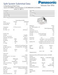
1-13. Example of Tubing Size Selection and Refrigerant Charge Amount<br />
Additional refrigerant charging<br />
Based on the values in Tables 1-3, 4, 5, 7, 10-1 and 10-2, use the liquid tubing size and length, and calculate the amount of additional<br />
refrigerant charge using the formula below.<br />
Required additional<br />
refrigerant charge (oz)<br />
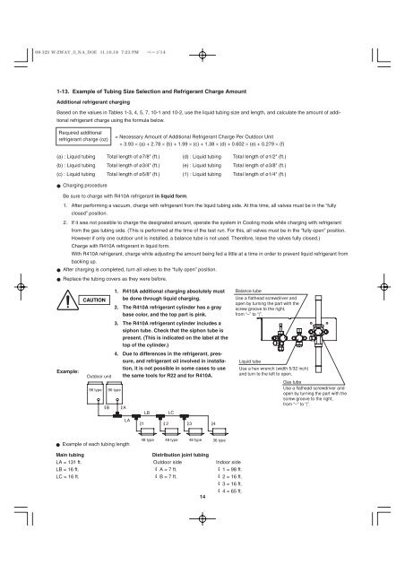
Example:<br />
CAUTION<br />
Outdoor unit<br />
96 type 96 type<br />
B<br />
A<br />
LA<br />
● Example of each tubing length<br />
= Necessary Amount of Additional Refrigerant Charge Per Outdoor Unit<br />
+ 3.93 × (a) + 2.78 × (b) + 1.99 × (c) + 1.38 × (d) + 0.602 × (e) + 0.279 × (f)<br />
(a) : Liquid tubing Total length of ø7/8" (ft.) (d) : Liquid tubing Total length of ø1/2" (ft.)<br />
(b) : Liquid tubing Total length of ø3/4" (ft.) (e) : Liquid tubing Total length of ø3/8" (ft.)<br />
(c) : Liquid tubing Total length of ø5/8" (ft.) ( f ) : Liquid tubing Total length of ø1/4" (ft.)<br />
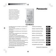
● Charging procedure<br />
Be sure to charge with R410A refrigerant in liquid form.<br />
1. After performing a vacuum, charge with refrigerant from the liquid tubing side. At this time, all valves must be in the “fully<br />
closed” position.<br />
2. If it was not possible to charge the designated amount, operate the system in Cooling mode while charging with refrigerant<br />
from the gas tubing side. (This is performed at the time of the test run. For this, all valves must be in the “fully open” position.<br />
However if only one outdoor unit is installed, a balance tube is not used. Therefore, leave the valves fully closed.)<br />
Charge with R410A refrigerant in liquid form.<br />
With R410A refrigerant, charge while adjusting the amount being fed a little at a time in order to prevent liquid refrigerant from<br />
backing up.<br />
● After charging is completed, turn all valves to the “fully open” position.<br />
● Replace the tubing covers as they were before.<br />
1. R410A additional charging absolutely must<br />
be done through liquid charging.<br />
2. The R410A refrigerant cylinder has a gray<br />
base color, and the top part is pink.<br />
3. The R410A refrigerant cylinder includes a<br />
siphon tube. Check that the siphon tube is<br />
present. (This is indicated on the label at the<br />
top of the cylinder.)<br />
4. Due to differences in the refrigerant, pressure,<br />
and refrigerant oil involved in installation,<br />
it is not possible in some cases to use<br />
the same tools for R22 and for R410A.<br />
LB LC<br />
1 2 3 4<br />
48 type 48 type 48 type 36 type<br />
Main tubing Distribution joint tubing<br />
LA = 131 ft. Outdoor side Indoor side<br />
LB = 16 ft. A = 7 ft. 1 = 98 ft.<br />
LC = 16 ft. B = 7 ft.<br />
14<br />
2 = 16 ft.<br />
3 = 16 ft.<br />
4 = 65 ft.<br />
Balance tube<br />
Use a flathead screwdriver and<br />
open by turning the part with the<br />
screw groove to the right,<br />
from “–” to “|”.<br />
Liquid tube<br />
Use a hex wrench (width 5/32 inch)<br />
and turn to the left to open.<br />
Gas tube<br />
Use a flathead screwdriver and<br />
open by turning the part with the<br />
screw groove to the right,<br />
from “–” to “|”.