ECOi 2 Way Installation Manual - Panasonic
ECOi 2 Way Installation Manual - Panasonic
ECOi 2 Way Installation Manual - Panasonic

Create successful ePaper yourself
Turn your PDF publications into a flip-book with our unique Google optimized e-Paper software.
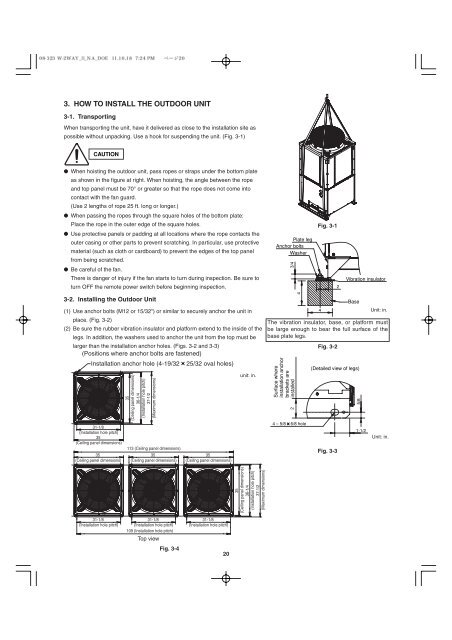
3. HOW TO INSTALL THE OUTDOOR UNIT<br />
3-1. Transporting<br />
When transporting the unit, have it delivered as close to the installation site as<br />
possible without unpacking. Use a hook for suspending the unit. (Fig. 3-1)<br />
CAUTION<br />
● When hoisting the outdoor unit, pass ropes or straps under the bottom plate<br />
as shown in the figure at right. When hoisting, the angle between the rope<br />
and top panel must be 70° or greater so that the rope does not come into<br />
contact with the fan guard.<br />
(Use 2 lengths of rope 25 ft. long or longer.)<br />
● When passing the ropes through the square holes of the bottom plate:<br />
Place the rope in the outer edge of the square holes.<br />
● Use protective panels or padding at all locations where the rope contacts the<br />
outer casing or other parts to prevent scratching. In particular, use protective<br />
material (such as cloth or cardboard) to prevent the edges of the top panel<br />
from being scratched.<br />
● Be careful of the fan.<br />
There is danger of injury if the fan starts to turn during inspection. Be sure to<br />
turn OFF the remote power switch before beginning inspection.<br />
3-2. Installing the Outdoor Unit<br />
(1) Use anchor bolts (M12 or 15/32") or similar to securely anchor the unit in<br />
place. (Fig. 3-2)<br />
(2) Be sure the rubber vibration insulator and platform extend to the inside of the<br />
legs. In addition, the washers used to anchor the unit from the top must be<br />
larger than the installation anchor holes. (Figs. 3-2 and 3-3)<br />
(Positions where anchor bolts are fastened)<br />
<strong>Installation</strong> anchor hole (4-19/32 25/32 oval holes)<br />
31-1/8<br />
(<strong>Installation</strong> hole pitch)<br />
35<br />
(Ceiling panel dimensions)<br />
35<br />
(Ceiling panel dimensions)<br />
3<br />
31-1/8<br />
(<strong>Installation</strong> hole pitch)<br />
35<br />
(Ceiling panel dimensions)<br />
36-1/4<br />
(<strong>Installation</strong> hole pitch)<br />
37-1/2<br />
(Maximum dimensions)<br />
113 (Ceiling panel dimensions)<br />
35<br />
(Ceiling panel dimensions)<br />
31-1/8<br />
(<strong>Installation</strong> hole pitch)<br />
109 (<strong>Installation</strong> hole pitch)<br />
Top view<br />
Fig. 3-4<br />
35<br />
(Ceiling panel dimensions)<br />
31-1/8<br />
(<strong>Installation</strong> hole pitch)<br />
20<br />
unit: in.<br />
35<br />
(Ceiling panel dimensions)<br />
36-1/4<br />
(<strong>Installation</strong> hole pitch)<br />
37-1/2<br />
(Maximum dimensions)<br />
Plate leg<br />
Anchor bolts<br />
Washer<br />
3/4<br />
Surface where<br />
installation anchor<br />
brackets are<br />
installed<br />
2<br />
4<br />
4 – 5/8 6/8 hole<br />
Fig. 3-1<br />
4<br />
Fig. 3-2<br />
Fig. 3-3<br />
2<br />
Vibration insulator<br />
Base<br />
(Detailed view of legs)<br />
5/8<br />
1-1/2<br />
Unit: in.<br />
The vibration insulator, base, or platform must<br />
be large enough to bear the full surface of the<br />
base plate legs.<br />
Unit: in.