Microstructure-Properties: I Fracture Toughness - Materials Science ...
Microstructure-Properties: I Fracture Toughness - Materials Science ...
Microstructure-Properties: I Fracture Toughness - Materials Science ...

Create successful ePaper yourself
Turn your PDF publications into a flip-book with our unique Google optimized e-Paper software.
1<br />
Objective<br />
Overview<br />
Crack<br />
Minimztn.<br />
Energy<br />
Absrptin.<br />
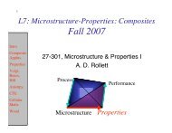
<strong>Microstructure</strong>-<strong>Properties</strong>: I<br />
<strong>Fracture</strong> <strong>Toughness</strong>: how to<br />
maximize it through<br />
microstructure control<br />
27-301<br />
Lecture 6C<br />
Fall, 2007<br />
Prof. A. D. Rollett<br />
Processing<br />
Performance<br />
<strong>Microstructure</strong> <strong>Properties</strong>
2<br />
Happy Guy Fawkes Day (Nov. 5th)!<br />
Objective<br />
Overview<br />
Crack<br />
Minimztn.<br />
Energy<br />
Absrptin.
3<br />
Objective<br />
Overview<br />
Crack<br />
Minimztn.<br />
Energy<br />
Absrptin.<br />
Objective<br />
• The objective of this lecture is to show you how to<br />
exploit microstructure in order to maximize<br />
toughness, especially in brittle materials.<br />
• Part of the motivation for this lecture is to prepare<br />
the class for a Lab on the sensitivity of mechanical<br />
properties to microstructure.<br />
• Note that the equations used are not derived -<br />
rather the emphasis is on basic principles and a<br />
broad range of methods for toughening.
4<br />
Objective<br />
Overview<br />
Crack<br />
Minimztn.<br />
Energy<br />
Absrptin.<br />
Applications?<br />
Why do we care about toughness?<br />
• Steels are used to build pressure vessels for<br />
nuclear reactors. The irradiation that these<br />
vessels experience, however, lowers the<br />
toughness of the steels. This must be allowed for<br />
in the design and operation of the reactors.<br />
http://ecow.engr.wisc.edu/cgi-bin/get/neep/541/allentodd/notes/<br />
Courtney<br />
(Ch. 13)
5<br />
Objective<br />
Overview<br />
Crack<br />
Minimztn.<br />
Energy<br />
Absrptin.<br />
Applications: ceramic gas turbines<br />
• The thermal efficiency of a gas turbine engine is directly related to its operating<br />
temperature. Conventional gas turbines use Ni-based alloys whose operating<br />
temperature is limited by their melting point (although clever design of thermal<br />
barrier coatings and cooling has dramatically raised their capabilities).<br />
Ceramic (oxide) components have much higher melting/softening points but<br />
their intrinsic toughness is far too low. Therefore the toughening of structural<br />
ceramics is essential if these systems are to succeed. The silicon nitridebased<br />
part shown (left) has machined strengths of up to 960 MPa and asprocessed<br />
strengths of up to 706 MPa.<br />
www1.eere.energy.gov/vehiclesandfuels/pdfs/success/advanced_gas_turbine.pdf<br />
www.p2pays.org/ref%5C08/07468.pdf -
6<br />
Objective<br />
Overview<br />
Crack<br />
Minimztn.<br />
Energy<br />
Absrptin.<br />
Key Points<br />
• Maximizing fracture resistance requires maximizing work done<br />
in breaking a material.<br />
• Minimize defect content, especially voids, cracks in brittle<br />
materials.<br />
• Increasing toughness generally requires adding additional<br />
structural components to a material, either at the microscopic<br />
scale or by making a composite.<br />
• If appropriate (in relation to the way in which a material is<br />
loaded), laminate the material i.e. put in crack deflecting<br />
planes.<br />
• If appropriate (in relation to the way in which a material is<br />
loaded), include stiff fibers in the material to give load transfer<br />
and fiber pull-out.<br />
• Design the composite to have inclusions that deflect the crack<br />
path.<br />
• Design the composite to include particles that transform (or<br />
crack) and thus require work to be done for crack propagation<br />
to take place.
7<br />
Objective<br />
Overview<br />
Crack<br />
Minimztn.<br />
Energy<br />
Absrptin.<br />
Strength versus toughness<br />
• If you imagine testing the (tensile) strength of a<br />
material that you could make arbitrarily tough or<br />
brittle, how would its measured strength vary?<br />
Breaking Strength<br />
?<br />
<strong>Toughness</strong>
8<br />
Objective<br />
Overview<br />
Crack<br />
Minimztn.<br />
Energy<br />
Absrptin.<br />
Strategies for toughness and<br />
microstructure<br />
• Yield strength depends on the obstacles to<br />
dislocation motion.<br />
• <strong>Toughness</strong> is more complex: there is no<br />
direct equivalent to obstacles to dislocation<br />
motion.<br />
• Instead, we must look for ways to (a)<br />
eliminate or minimize cracks; (b) ways to<br />
maximize the energy cost of propagating a<br />
crack.
9<br />
Objective<br />
Overview<br />
Crack<br />
Minimztn.<br />
Energy<br />
Absrptin.<br />
(a) Minimize/eliminate<br />
Minimize/ eliminate cracks<br />
• How do we eliminate cracks?<br />
• First, consider the sources of cracks:<br />
- in metals, voids from solidification are deleterious<br />
(especially in fatigue), so minimizing gas content<br />
during solidification helps (Metals Processing!).<br />
- rough surfaces (e.g. from machining) can be<br />
made smooth.<br />
- also in metals, large, poorly bonded (to the<br />
matrix) second phase particles are deleterious,<br />
e.g. oxide particles. Therefore removal of<br />
interstitials (O, N, C, S) from steel melts (or Fe &<br />
Si from Al) is important because they tend to react<br />
with the base metal to form brittle inclusions (as in,<br />
e.g. clean steel technology).
10<br />
Objective<br />
Overview<br />
Crack<br />
Minimztn.<br />
Energy<br />
Absrptin.<br />
(a) Minimize/eliminate Minimize/eliminate<br />
cracks<br />
• How do we minimize cracks?<br />
Grain Structure:<br />
- there are various mechanisms that lead to cracks at grain<br />
boundaries, or at triple junctions between boundaries.<br />
Therefore - in some materials - making the grain size as small<br />
as possible is important because it determines the maximum<br />
crack size. Crack size matters because of stress<br />
concentration at the crack tip: longer cracks mean higher<br />
stress concentrations.<br />
- how to minimize grain size? Either by thermomechanical<br />
processing (maximum strain + minimum recrystallization<br />
temperature) or by starting with small powders and<br />
consolidating to 100% density.
11<br />
Objective<br />
Overview<br />
Crack<br />
Minimztn.<br />
Energy<br />
Absrptin.<br />
Distributions<br />
• Remembering that it is the largest crack that limits<br />
breaking strength, it is not the average crack length<br />
that matters but rather the maximum crack size that<br />
we should care about.<br />
• For materials in which the grain size determines the<br />
typical crack size, experience shows that the grain<br />
size distribution is approximately constant. The<br />
maximum grain size observed is a small multiple of<br />
the average - about 2.5 times.<br />
• Also important in distributions is the spatial<br />
distribution of particles (that can generate cracks);<br />
cracks at, or near the surface are more deleterious<br />
than cracks in the interior.
12<br />
Objective<br />
Overview<br />
Crack<br />
Minimztn.<br />
Energy<br />
Absrptin.<br />
Spatial Distributions<br />
• Anisotropic spatial distributions are most commonly<br />
encountered in thermomechanically processed<br />
metals. They occur, for example, in silicon nitride<br />
processed (tape casting + sintering) to promote<br />
directional growth of beta-Si 3 N 4 for high thermal<br />
conductivity heat sink materials.<br />
• The sensitivity of toughness to the direction in<br />
which the testing is performed has led to a special<br />
jargon for specimen orientation.
13<br />
Objective<br />
Overview<br />
Crack<br />
Minimztn.<br />
Energy<br />
Absrptin.<br />
Specimen Orientation Code<br />
• The first letter denotes the loading direction; the<br />
second letter denotes the direction in which crack<br />
propagation occurs.<br />
[Hertzberg]
14<br />
Objective<br />
Overview<br />
Crack<br />
Minimztn.<br />
Energy<br />
Absrptin.<br />
Mechanical Fibering<br />
• Any second phase particles present from solidification tend to<br />
be elongated and dispersed in sheets parallel to the rolling<br />
plane; called “stringers”.<br />
• <strong>Toughness</strong> in the S-L or S-T orientations is typically much<br />
lower than for the L-T or L-S orientations because the crack<br />
plane is parallel to the planes on which the particles lie close<br />
to one another.<br />
[Hertzberg]<br />
Lowest<br />
toughness
15<br />
Objective<br />
Overview<br />
Crack<br />
Minimztn.<br />
Energy<br />
Absrptin.<br />
Inclusion effects<br />
• Graph plots variation<br />
in strength with (plane<br />
strain) toughness with<br />
varying sulfur contents<br />
in 0.45C-Ni-Cr-Mo<br />
steels.<br />
• Increasing levels of S<br />
lead to lower<br />
toughness at the same<br />
strength level.<br />
• This occurs because<br />
the sulfur is present as<br />
sulfide inclusions in<br />
the steel.<br />
• “Clean steel”<br />
technologies have<br />
reduced this problem<br />
in recent years. [Dieter]
16<br />
Objective<br />
Overview<br />
Crack<br />
Minimztn.<br />
Energy<br />
Absrptin.<br />
[Hertzberg]<br />
Laminate Composites<br />
• The weakness of such layers of inclusions, which provide planes on<br />
which crack nucleation is relatively easy, can however be exploited.<br />
• By providing planes of low crack resistance perpendicular to the<br />
anticipated crack propagation direction, a crack can be deflected,<br />
thereby reducing the load at the crack tip.<br />
• In designing a laminate composite, it is important to balance the<br />
fracture toughness (brittleness) against the interfacial weakness.<br />
The more brittle the matrix (layers), the weaker the interfaces<br />
between the layers need to be. Example: Wood, Mollusc shells
17<br />
Objective<br />
Overview<br />
Crack<br />
Minimztn.<br />
Energy<br />
Absrptin.<br />
Effect of lamination on the DBTT<br />
• The effect of orienting the laminations of a<br />
composite in the crack arrestor configuration is to<br />
dramatically lower the transition temperature.<br />
• This is actually an example of crack deflection.<br />
[Hertzberg, after Embury]
18<br />
Objective<br />
Overview<br />
Crack<br />
Minimztn.<br />
Energy<br />
Absrptin.<br />
Explanation of Lamination<br />
This crack propagation<br />
direction follows the<br />
inclusion+grain shape<br />
(less toughness)<br />
This crack propagation<br />
direction leads to<br />
delamination and crack<br />
blunting (more<br />
toughness)
19<br />
Objective<br />
Overview<br />
Crack<br />
Minimztn.<br />
Energy<br />
Absrptin.<br />
Energy absorption: 1<br />
• How do we increase the amount of energy consumed in<br />
propagating a crack?<br />
- One method, already discussed, is to maximize the amount<br />
of plastic work. This requires the yield strength to be<br />
minimized so as to maximize the size of the plastic zone.<br />
- For very tough materials, however, it turns out that the same<br />
parameters that control ductility also affect toughness. Lower<br />
densities of second phase particle increase toughness.<br />
Second phase particles well bonded to the matrix increase<br />
toughness. Small differences in thermal expansion coefficient<br />
help (Why?).<br />
• Read papers by Prof. Warren Garrison’s group.
20<br />
Objective<br />
Overview<br />
Crack<br />
Minimztn.<br />
Energy<br />
Absrptin.<br />
Energy absorption: 2<br />
• Other methods of toughening materials are generally called<br />
extrinsic. There are three general classes of approach:<br />
1) Crack deflection (and meandering)<br />
2) Zone shielding<br />
3) Contact shielding<br />
• The term “shielding” means that the crack tip is shielded from<br />
some part of the applied stress.<br />
• Up to this point, the discussion has been mostly about metalbased<br />
materials which are intrinsically tough to being with<br />
(except at low temperatures). Extrinsic toughening methods<br />
are mostly concerned with ceramics in which the intrinsic<br />
toughness is low.
21<br />
Objective<br />
Overview<br />
Crack<br />
Minimztn.<br />
Energy<br />
Absrptin.<br />
Energy absorption: 3<br />
• Sub-divisions of extrinsic toughening methods:<br />
1) Crack deflection (and meandering)<br />
2) Zone shielding<br />
- 2A Transformation Toughening<br />
- 2B Microcrack toughening<br />
- 2C Void formation<br />
3) Contact shielding<br />
- 3A Wedging/ crack bridging<br />
- 3B Ligament/fiber bridging<br />
- 3C Crack sliding, interference<br />
- 3D Plasticity induced crack closure
22<br />
Objective<br />
Overview<br />
Crack<br />
Minimztn.<br />
Energy<br />
Absrptin.<br />
1 Crack deflection<br />
• If particles of a second phase are present, large differences in<br />
elastic modulus can either attract or repel the crack.<br />
• Some authors (e.g. Green) distinguish between crack bowing<br />
and crack deflection. Technically, the former is toughening<br />
from deflection in the plane of the crack and the latter is<br />
deflection out of the plane of the crack.<br />
• In either case, the net result is that the crack tip no longer<br />
sees as large a stress as it would if the crack were straight,<br />
and in the plane.<br />
• Crack deflection can be caused by particles that are more<br />
resistant to cracking, or have different elastic stiffness (higher<br />
or lower modulus).<br />
• Laminate composites also achieve crack deflection, as<br />
previously discussed.
23<br />
Objective<br />
Overview<br />
Crack<br />
Minimztn.<br />
Energy<br />
Absrptin.<br />
1. Crack<br />
deflection:<br />
examples<br />
[Green]
24<br />
Zone Shielding: 2A transformation toughening<br />
Objective<br />
Overview<br />
Crack<br />
Minimztn.<br />
Energy<br />
Absrptin.<br />
• Various mechanisms exist for shielding crack tips from some<br />
of the applied (and concentrated) stress.<br />
• The best known mechanism is transformation toughening.<br />
• This applies to both metals (stainless steels, Hadfield steels)<br />
and ceramics (zirconia additions).<br />
• The principle on which the toughening is based is that of<br />
including a phase that is metastable at the service<br />
temperature and which will transform when loaded (but not<br />
otherwise).<br />
• The transformation always has a volume change associated<br />
with the change in crystal structure, which can be written as a<br />
strain. The product of stress and strain is then the work done<br />
or expended during the (stress-induced) transformation.
25<br />
Objective<br />
Overview<br />
Crack<br />
Minimztn.<br />
Energy<br />
Absrptin.<br />
2A Transformation toughening:<br />
transformation strain<br />
• The large volume change on transformation is<br />
equivalent to a significant transformation strain which<br />
is the key to the success of the method. Recall that<br />
our basic measure of fracture resistance is the work<br />
done, ∫ σdε, in breaking the material.<br />
• The volume change (dε) is ~ 4%, accompanied by a<br />
shear strain of ~ 7%. Since the transformation has a<br />
particular habit plane (i.e. a crystallographic plane in<br />
each phase in common), two twin-related variants<br />
occur in each particle so that the shear strains are<br />
(approximately) canceled out. This leaves only the<br />
4% dilatational (volume) strain that contributes to the<br />
work done.
2A Transformation toughening: phase<br />
2A<br />
26<br />
Transformation toughening: phase<br />
Objective<br />
Overview<br />
Crack<br />
Minimztn.<br />
Energy<br />
Absrptin.<br />
change in zirconia<br />
• The classic example of transformation toughening is the<br />
addition of a few (volume) % of ZrO 2 to oxides and other brittle<br />
ceramics.<br />
• The high temperature form of zirconia is a tetragonal form (t-<br />
ZrO 2 ) which has a significantly larger atomic volume than the<br />
low temperature, monoclinic form (m-ZrO 2 ).<br />
• In order to reduce the driving force for the tetragonal <br />
monoclinic transformation (i.e. lower the transformation<br />
temperature), some “stabilizer” is added. Typical are ceria<br />
(Ce 2 O 3 ) and yttria (Y 2 O 3 ).<br />
• The subtle point about this approach is that some “trick” is<br />
needed in order to keep the zirconia from transforming once<br />
the material is cooled to room temperature, i.e. to maintain it<br />
in a metastable, untransformed state.
27<br />
Objective<br />
Overview<br />
Crack<br />
Minimztn.<br />
Energy<br />
Absrptin.<br />
2A Transformation toughening:<br />
critical size of zirconia particles<br />
• An important consequence of the volume change on<br />
transformation is that it leads to an elastic driving force that<br />
opposes the transformation for particles embedded in a matrix<br />
of a different material.<br />
• Therefore we take advantage of having the zirconia<br />
embedded as small particles in the matrix of the ceramic to be<br />
toughened.<br />
• The particles must be small enough for the elastic energy term<br />
to be effective. The upper limit for retention of the high<br />
temperature (tetragonal) phase is ~ 0.5 µm.<br />
[Green]
28<br />
Objective<br />
Overview<br />
Crack<br />
Minimztn.<br />
Energy<br />
Absrptin.<br />
2A Transformation toughening:<br />
transformation →→ work<br />
• Consider the effect of the tensile stress in the vicinity of the<br />
crack tip: the stress removes the constraint on each particle,<br />
allowing it to transform. The transformed particle was<br />
metastable, thermodynamically, and so remains in the low T,<br />
monoclinic form after the crack has gone by.<br />
• The stress acting to cause the transformation strain performs<br />
work and so energy is consumed in the phase transformation.<br />
This energy (work done) adds to the surface energy required<br />
to create crack length.<br />
• Additional toughening arises from the particles causing crack<br />
deflection.
29<br />
Objective<br />
Overview<br />
Crack<br />
Minimztn.<br />
Energy<br />
Absrptin.<br />
2A Transformation toughening:<br />
the process zone<br />
• The region in which transformation occurs becomes<br />
the crack wake as the crack propagates. The<br />
region around the crack tip is known as the process<br />
zone because this is where the toughening process<br />
is operative.<br />
Process zone width<br />
Crack propagation direction<br />
[Green]
30<br />
Objective<br />
Overview<br />
Crack<br />
Minimztn.<br />
Energy<br />
Absrptin.<br />
2A Transformation toughening:<br />
microstructure<br />
• Microstructural evidence for<br />
the transformation is<br />
obtainable through x-ray<br />
diffraction and Raman<br />
spectroscopy (the two different<br />
forms of zirconia have quite<br />
different infra-red spectra).<br />
• (a) lenticular particles of MgOstabilized<br />
ZrO 2 (untransformed)<br />
in cubic ZrO 2 .<br />
(b) transformed particles of<br />
ZrO 2 around a crack (dashed<br />
line).<br />
[Chiang]
31<br />
Objective<br />
Overview<br />
Crack<br />
Minimztn.<br />
Energy<br />
Absrptin.<br />
2A Transformation toughening:<br />
limits on toughening<br />
• As the particle size is<br />
increased, so the particles<br />
become less and less<br />
stable; the transformation<br />
becomes easier and more<br />
effective at toughening the<br />
material. If the particles<br />
become too large, however,<br />
the toughening is lost<br />
because the particles are no<br />
longer stabilized in their<br />
high temperature form.<br />
• Effect of test temperature?<br />
• Effect of stabilizing additions<br />
to the ZrO2 ?<br />
[Green]
32<br />
Objective<br />
Overview<br />
Crack<br />
Minimztn.<br />
Energy<br />
Absrptin.<br />
2A Transformation toughening:<br />
quantitative approach<br />
• It is not possible to lay out the details of how to<br />
describe transformation toughening in a fully<br />
quantitative fashion here.<br />
• An equation that describes the toughening effect is as<br />
follows, where K is the increment in toughness (units of<br />
stress intensity, MPa√m):<br />
∆K = C E V trans ε trans √h / (1-ν)<br />
C is a constant (of order 1), E = elastic modulus,<br />
V trans = volume fraction transformed,<br />
ε trans = transformation strain (dilatation, i.e. bulk<br />
expansion), h is the width of the process zone, and ν is<br />
Poisson’s ratio.<br />
• What controls the width of the process zone?
33<br />
Objective<br />
Overview<br />
Crack<br />
Minimztn.<br />
Energy<br />
Absrptin.<br />
2B Microcracking<br />
• Less effective than transformation toughening is<br />
microcracking in the process zone.<br />
• Microstructural elements are included that crack<br />
over limited distances and only at the elevated<br />
(tensile) stresses present in the crack tip.<br />
[Green]
34<br />
Objective<br />
Overview<br />
Crack<br />
Minimztn.<br />
Energy<br />
Absrptin.<br />
2B Microcracking<br />
• The principle of Micro-cracking as a toughening mechanism is that one<br />
designs the material so that additional (micro-)cracking occurs in the vicinity<br />
of the crack tip as it advances, thereby increasing the crack area created<br />
(per unit advance of crack), thereby increasing the toughness (resistance to<br />
crack propagation).<br />
• This is most effective in two-phase ceramics in which the 2 phases have<br />
different CTEs. As the material cools after sintering (or other high<br />
temperature processing), one phase is in tension (and the other in<br />
compression, to balance). The phase under residual tensile stress will<br />
crack more easily than the other one under additional tensile load, e.g. near<br />
a crack tip.<br />
• Now we have to consider what can happen in the material. If the residual<br />
stress is too high, then the phase in tension will crack during cooling. If it is<br />
entirely (micro-)cracked, then no further cracking can occur at a crack tip (to<br />
absorb energy) and the toughening effect is lost. What controls this,<br />
however, is the grain size: smaller grain sizes are more resistant to<br />
cracking. To find the critical grain size, d c , we use the Griffith equation, with<br />
K co as the fracture toughness and σ R as the residual stress, substituting<br />
grain size for crack size:<br />
d c = ( K co / σ R ) 2<br />
• The process zone size, r c , then depends on the ratio of the actual grain<br />
size, d, to the critical grain size:<br />
• The graph, from Courtney, shows how one needs to be within a certain<br />
rather narrow range of grain size in order to have a finite process zone size<br />
and therefore effective toughening. Grain sizes larger than the critical grain<br />
size simply result in spontaneous cracking. Too small grain sizes (
35<br />
Objective<br />
Overview<br />
Crack<br />
Minimztn.<br />
Energy<br />
Absrptin.<br />
2B Microcracking: Microcracking:<br />
particles<br />
• Microcracking depends on second phase particles that can crack<br />
easily.<br />
• The cracking tendency depends on particle size: if they are too small,<br />
then the stress intensity does not reach their critical K (typically, 1µm),<br />
based on the Griffith equation.<br />
• (Tensile) residual stresses aid cracking, so differences in thermal<br />
expansion (with the matrix) are important.<br />
• An equation that describes the toughening effect is as follows, where<br />
K is again the increment in toughness (units of stress intensity):<br />
∆K = C E ε crack √h / (1-ν)<br />
C is a constant (of order 1), E = modulus, ε crack = cracking strain<br />
(dilatation) h is the width of the process zone, and ν is Poisson’s ratio.<br />
The cracking strain is approximately the strain associated with the<br />
difference in CTE: ε crack ≈ ∆α ∆T.<br />
• Note the strong similarity to the equation that describes<br />
transformation toughening! The only difference is the physical<br />
meaning of the strain term.
36<br />
Objective<br />
Overview<br />
Crack<br />
Minimztn.<br />
Energy<br />
Absrptin.<br />
2C Void formation<br />
• Void formation in a process zone can have a similar<br />
effect to micro-cracking. In materials such as high<br />
strength steels, e.g. 4340, the source of the voiding<br />
is ductile tearing on a small scale as the crack<br />
opens.<br />
• The spatial organization of the voids is important.<br />
Random distributions are better than either clusters<br />
or sheets. Carbide particles in steels, or dispersoid<br />
particles in aluminum alloys (e.g. Al 3 Fe) are typical<br />
nucleation sites for voids. Sheet-like sets of voids<br />
can arise from carbide particles that have grown on<br />
martensite or bainite laths during tempering of<br />
martensitic microstructures.
37<br />
Objective<br />
Overview<br />
Crack<br />
Minimztn.<br />
Energy<br />
Absrptin.<br />
3A Crack wedging/ bridging<br />
• Wherever the crack results in interlocking grain<br />
shapes exerting force across the crack, stress<br />
(intensity) at the crack tip is reduced.<br />
[Chiang]<br />
Crack<br />
opening
38<br />
Objective<br />
Overview<br />
Crack<br />
Minimztn.<br />
Energy<br />
Absrptin.<br />
3B Fiber/ligament bridging (Composites)<br />
• Anything that results in a load bearing link across the crack (behind<br />
the tip) decreases the stress (intensity) at the crack tip.<br />
• Either rigid (elastic) fibers (ceramic matrix composites) or plastic<br />
particles (ductile metal particles in an elastic matrix) are effective.<br />
• In order to estimate the increase in toughness, one can calculate a<br />
work associated with crack advance and then estimate with<br />
∆K = √(EG).<br />
[Chiang]
39<br />
Objective<br />
Overview<br />
Crack<br />
Minimztn.<br />
Energy<br />
Absrptin.<br />
3B Fiber/ligament bridging<br />
• Scanning electron micrographs of a SiC whisker<br />
bridging at various stages of crack opening. From<br />
left to right, the stress intensity is increasing.<br />
[Green]
40<br />
Objective<br />
Overview<br />
Crack<br />
Minimztn.<br />
Energy<br />
Absrptin.<br />
3B Fiber/ligament bridging<br />
strain dependence<br />
• The balance<br />
between fiber<br />
strength, matrix<br />
strength and the<br />
fiber/matrix<br />
interface is critical.<br />
• In general, a<br />
relatively weak<br />
fiber/matrix<br />
interface<br />
promotes<br />
toughness.<br />
• Why? [Green]
41<br />
3D Plasticity induced crack closure<br />
Objective<br />
Overview<br />
Crack<br />
Minimztn.<br />
Energy<br />
Absrptin.<br />
• Plasticity induced crack closure is<br />
another way of stating the effect of<br />
plastic deformation around the crack tip.<br />
• Very tough materials exhibit an<br />
interesting behavior in Charpy impacts.<br />
For high ductilities, the specimen can<br />
deform without fully breaking, with<br />
consequent enormous energies<br />
absorbed.
42<br />
Objective<br />
Overview<br />
Crack<br />
Minimztn.<br />
Energy<br />
Absrptin.<br />
References<br />
• D.J. Green (1998). An Introduction to the Mechanical<br />
<strong>Properties</strong> of Ceramics, Cambridge Univ. Press, NY.<br />
• <strong>Materials</strong> Principles & Practice, Butterworth<br />
Heinemann, Edited by C. Newey & G. Weaver.<br />
• G.E. Dieter, Mechanical Metallurgy, McGrawHill, 3rd<br />
Ed.<br />
• Courtney, T. H. (2000). Mechanical Behavior of<br />
<strong>Materials</strong>. Boston, McGraw-Hill.<br />
• R.W. Hertzberg (1976), Deformation and <strong>Fracture</strong><br />
Mechanics of Engineering <strong>Materials</strong>, Wiley.<br />
• N.E. Dowling (1998), Mechanical Behavior of<br />
<strong>Materials</strong>, Prentice Hall.<br />
• A.H. Cottrell (1964), The Mechanical <strong>Properties</strong> of<br />
Matter, Wiley, NY.
43<br />
Objective<br />
Overview<br />
Crack<br />
Minimztn.<br />
Energy<br />
Absrptin.<br />
Lab 2: points of interest<br />
• Consider the following items in the (second) Lab.<br />
• Relate the fracture morphology of wood to what we discussed<br />
in this lecture concerning laminated composites.<br />
• Can you detect changes in fracture morphology as a function of<br />
test temperature (steels)? Can you relate the fracture surface<br />
features to the measured grain size? What about the spacing<br />
of the pearlite colonies (depending on the microstructure)?<br />
• Can you detect changes in fracture morphology as a function of<br />
microstructural change? For example, in the normalized<br />
(pearlitic) condition, can you detect the lamellae at the fracture<br />
surface? Do you think that there is any interaction between the<br />
fracture process and the lamellar structure?<br />
• For the quench+tempered condition, can you relate the particle<br />
(carbide) spacing to features on the fracture surface?<br />
• For the martensitic condition, can you estimate the energy that<br />
should be absorbed if it goes only towards creating crack<br />
surface? How does this number compare with a reasonable<br />
surface energy for iron?