Precision Grating and Optics for Space Research
Precision Grating and Optics for Space Research
Precision Grating and Optics for Space Research

You also want an ePaper? Increase the reach of your titles
YUMPU automatically turns print PDFs into web optimized ePapers that Google loves.
<strong>Precision</strong> <strong>Grating</strong> <strong>and</strong> <strong>Optics</strong> <strong>for</strong> <strong>Space</strong> <strong>Research</strong><br />
Mark L. Schattenburg<br />
<strong>Space</strong> Nanotechnology Laboratory<br />
Kavli Institute <strong>for</strong> Astrophysics <strong>and</strong> <strong>Space</strong> <strong>Research</strong><br />
Massachusetts Institute of Technology<br />
University of Alabama at Huntsville<br />
Aug. 5, 2005<br />
<strong>Space</strong> Nanotechnology Laboratory<br />
SNL<br />
Massachusetts Institute of Technology
Bizarre-Universe.eps<br />
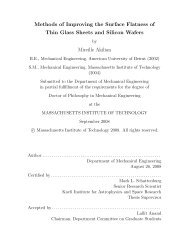
Supernova Remnant<br />
Huge jets many times longer than our galaxy.<br />
Exhaust from the supermassive black hole.<br />
Supernovae can emit more energy than<br />
the combined output of all the billions of stars in our galaxy.<br />
Supermassive Black Hole<br />
Our Bizarre Universe<br />
The centers of galaxies harbor black holes that can have<br />
more mass than all the stars of our galaxy combined.<br />
Star Being Eaten by Black Hole<br />
Cosmic vacuum cleaner.<br />
Galactic Jet<br />
Huge jets many times longer than our galaxy<br />
are the exhaust from supermassive black holes.
MLS-01-03-14.02<br />
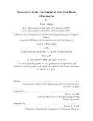
NASA Ch<strong>and</strong>ra Observatory X-ray Telescope<br />
Per<strong>for</strong>ms high-resolution x-ray imaging <strong>and</strong> spectroscopy in the<br />
energy range of 0.1-10 keV (wavelengths from 0.1 to 10 nanometers).<br />
Subrahmanyan<br />
Ch<strong>and</strong>rasekhar<br />
(1910-1995)<br />
Nobel Prize, 1983
cc_GrazingIncidence.ai<br />
θ c<br />
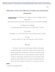
Principles of X-ray <strong>Optics</strong> at Grazing Incidence<br />
Refractive index <strong>for</strong> x-ray radiation:<br />
n(<br />
ω) = 1−<br />
δ ( ω)<br />
+ iβ<br />
( ω)<br />
where δ , β ∼<br />
Critical angle <strong>for</strong> total external reflection of x-rays:<br />
n = 1−<br />
δ + iβ<br />
θ<br />
Critical Ray<br />
Grazing Incidence Radiation <strong>and</strong><br />
Total External Reflection<br />
θ = 2δ<br />
c<br />
Totally<br />
Reflected<br />
Rays<br />
Reflectivity<br />
~10 -2<br />
1<br />
0.8<br />
0.6<br />
0.4<br />
0.2<br />
C<br />
A<br />
B<br />
D E<br />
0.5 1 1.5 2 2.5 3<br />
θ / θ c<br />
10 -4<br />
A : β / δ = 0<br />
B : β / δ = 10<br />
C : β / δ = 10<br />
D : β / δ = 1<br />
E : β / δ = 3<br />
−2<br />
−1
MLS-2001-05-23.01.eps<br />
X-rays<br />
Ch<strong>and</strong>ra Observatory Grazing Incidence <strong>Optics</strong><br />
(Wolter Type I)<br />
Nested<br />
Hyperboloids<br />
Nested<br />
Paraboloids<br />
1.1 Meter Diameter<br />
Doubly-<br />
Reflected<br />
X-rays<br />
10 Meters<br />
Focal<br />
Plane
Ch<strong>and</strong>ra-Mirror.eps<br />
Ch<strong>and</strong>ra X-ray Telescope Mirror Assembly<br />
Raytheon Optical Systems & Eastman Kodak Corp.
HETGS<br />
NASA Ch<strong>and</strong>ra Observatory X-ray Telescope<br />
High Energy Transmission <strong>Grating</strong> Spectrometer (HETGS)<br />
Aspect Camera<br />
Stray Light Shade<br />
High Resolution<br />
Mirror Assembly<br />
(HRMA)<br />
Sunshade<br />
Door<br />
Thrusters (4)<br />
(105 lb)<br />
Low Gain<br />
Antenna (2)<br />
<strong>Space</strong>craft<br />
Module<br />
Transmission<br />
<strong>Grating</strong>s (2)<br />
Optical<br />
Bench<br />
Ch<strong>and</strong>ra Telescope<br />
X-rays<br />
X-ray<br />
mirrors<br />
P H<br />
<strong>Grating</strong><br />
(in use)<br />
Solar Array (2)<br />
CCD Imaging<br />
Spectrometer<br />
(ACIS)<br />
High Resolution<br />
Camera (HRC)<br />
Integrated Science<br />
Instrument Module<br />
(ISIM)<br />
<strong>Grating</strong><br />
(stowed)<br />
CCD1 CCD2 CCD3 CCD4 CCD5 CCD6<br />
HETGS Instrument<br />
X-ray CCD<br />
Detector array<br />
θ<br />
Zero-order beams<br />
Diffracted beams<br />
Rowl<strong>and</strong> Torus Transmission <strong>Grating</strong> Geometry <strong>and</strong> CCD Readout Array
MLS-2001-05-11.01eps<br />
NASA Ch<strong>and</strong>ra X-ray Observatory<br />
High Energy Transmission <strong>Grating</strong> Spectrometer (HETGS)<br />
HETGS instrument.<br />
1.1 meter<br />
Invar grating frame.<br />
3 cm<br />
Scanning electron micrograph of gold grating.<br />
100 nm<br />
550 nm
E0102-72.eps<br />
Ch<strong>and</strong>ra X-ray Spectrum<br />
Small Magellanic Cloud Supernova Remant E0102-72<br />
Direct X-ray Image (CCD Camera)<br />
longer wavelengths <br />
shorter wavelengths<br />
X-ray Image Dispersed by Transmission <strong>Grating</strong>s<br />
Zero<br />
Order
MLS-1999-05-26.03.eps<br />
Variable<br />
Attenuator<br />
Mirror<br />
Beamsplitter<br />
p = λ<br />
2sinθ<br />
Interference Lithography<br />
Beamsplitter<br />
Spatial Filters<br />
2θ<br />
Pockels Cell<br />
Substrate<br />
Laser Beam<br />
λ = 351.1 nm<br />
Phase Error<br />
Sensor<br />
Mirror
MLS-94-05-13.01<br />
15 nm<br />
Ta 2 O 5<br />
0.5-1.0 µm<br />
ARC<br />
5 nm chromium<br />
20 nm gold<br />
200 nm<br />
resist<br />
0.5-1.0 µm<br />
polyimide µ<br />
d<br />
silicon wafer<br />
silicon<br />
(a) Prepare substrate.<br />
polyimide<br />
Membrane-Supported Transmission <strong>Grating</strong><br />
Fabrication Process - Macro View<br />
(b) Pattern gold grating.<br />
gold<br />
grating<br />
(c) Acid spin-etch wafer<br />
backside.<br />
adhesive<br />
(d) Bond to Invar frame.<br />
(e) Cut away.<br />
silicon<br />
Invar<br />
frame
MLS-94-05-13.02<br />
resist<br />
ARC<br />
polyimide<br />
silicon<br />
ARC<br />
polyimide<br />
silicon<br />
(b) Pattern by IL<br />
<strong>and</strong> develop.<br />
Membrane-Supported Transmission <strong>Grating</strong><br />
Fabrication Process - Micro View<br />
(a) Prepare<br />
substrate.<br />
interlayer<br />
plating<br />
base<br />
ARC<br />
polyimide<br />
silicon<br />
(c) Etch interlayer in<br />
CF 4 RIE plasma.<br />
polyimide<br />
silicon<br />
(d) Etch ARC in O 2<br />
RIE plasma.<br />
plated gold<br />
polyimide<br />
silicon<br />
(e) Gold electroplate.<br />
plated<br />
gold<br />
polyimide<br />
silicon<br />
(f) Strip interlayer<br />
<strong>and</strong> ARC.<br />
polyimide<br />
epoxy<br />
Invar<br />
(g) Acid spin-etch<br />
substrate.<br />
Align <strong>and</strong> bond<br />
to frames.
MLS-2001-05-25.02.eps<br />
Reflectivity from Resist/IL Boundary<br />
0.5<br />
0.4<br />
0.3<br />
0.2<br />
0.1<br />
0<br />
Gold Transmission <strong>Grating</strong> Fabrication Process<br />
Benefit of anti-reflection coating (ARC).<br />
Resist<br />
ARC<br />
Silicon<br />
Ta 2 O 5<br />
200 nm period<br />
λ = 351.1. nm<br />
TE polarization<br />
0 200 400 600 800<br />
ARC Thickness (nm)<br />
<strong>Grating</strong> after oxygen plasma RIE of ARC.<br />
100 nm<br />
600 nm<br />
<strong>Grating</strong> after interference lithography.<br />
100 nm<br />
<strong>Grating</strong> after gold plating <strong>and</strong> resist stripping.<br />
100 nm<br />
resist<br />
ARC<br />
Ta 2 O 5
MIT<br />
SNL<br />
NASA Constellation-X
MIT<br />
SNL<br />
Smooth Ch<strong>and</strong>ra Monolithic <strong>Optics</strong>
MIT X-ray Telescopes Utilizing Thin<br />
Required optic<br />
dimensions:<br />
100mmx140mmx0.4mm<br />
Length / thickness > 200<br />
SNL<br />
<strong>Optics</strong>
MIT<br />
SNL<br />
Grazing Incidence (Wolter I) <strong>and</strong><br />
Reflection <strong>Grating</strong> <strong>Optics</strong>
MLS-2002-08-19.01.eps<br />
100 mm<br />
p max<br />
X-ray Reflection <strong>Grating</strong> Geometry<br />
(Off-Plane Diffraction)<br />
pave
Super-Smooth Blazed Reflection <strong>Grating</strong>s From Miscut Silicon<br />
200 nm Resist<br />
30 nm SiN<br />
1. Coat with bilevel resist <strong>and</strong> pattern gratings.<br />
Silicon<br />
2. Plasma etch ARC <strong>and</strong> nitride.<br />
3. RCA clean.<br />
49 nm ARC<br />
(111) planes<br />
4. Anisotropic KOH etch.<br />
5. Remove nitride with HF.<br />
Resist<br />
Anti-reflection Coating (ARC)<br />
Nitride<br />
(111) planes
200 nm Si Master with 7º Blaze<br />
AFM probe<br />
100<br />
Silicon Master<br />
Scanned profile<br />
Actual profile<br />
• Roughness < 0.2 nm<br />
• Rounding = AFM artifact<br />
• Radius of probe ~ 10 nm<br />
Coated with Cr <strong>and</strong> Au<br />
Atomic Force Micrograph (AFM) Scanning Electron Micrograph (SEM)<br />
SNL MIT
MLS-1997-01-20.08.eps<br />
Resist<br />
Left<br />
Beam<br />
Interference Lithography<br />
2<br />
Substrate<br />
<strong>Grating</strong> Period p=/(2sin)<br />
Right<br />
Beam
MLS-2000-04-03.01.eps<br />
Spherical waves cause<br />
hyperbolic phase.<br />
Hyperbolic Phase<br />
Traditional Interference Lithography<br />
laser<br />
laser<br />
Figure errors & defects<br />
in collimating optics cause noise.<br />
Linear Phase + Noise
MLS-2000-04-04.02.eps<br />
Optical<br />
Bench<br />
Interferometer<br />
Scanning-Beam Interference Lithography<br />
Laser<br />
XY Stage<br />
Air Bearing Granite Block<br />
Substrate<br />
Y Direction<br />
Y Direction<br />
X Direction<br />
Parallel Scanning<br />
X Direction<br />
Doppler Scanning<br />
Scanning<br />
<strong>Grating</strong><br />
Image<br />
Air-Bearing<br />
X-Y Stage<br />
Resist-<br />
Coated<br />
Substrate<br />
Scanning<br />
<strong>Grating</strong><br />
Image
PTK-99-01-09-1<br />
Y Direction<br />
X Direction<br />
(a) Scanning Scheme<br />
Intensity<br />
Scan<br />
1<br />
<strong>Grating</strong> Scanning Method<br />
<strong>Grating</strong><br />
Image<br />
Air-Bearing<br />
Stage<br />
Substrate<br />
Summed Intensity<br />
of Scans 1-6<br />
Scan<br />
2 Scan<br />
3<br />
Scan<br />
4<br />
Scan<br />
5<br />
Intensity<br />
Scan<br />
6<br />
(b) Image Intensity Profile<br />
(c) Overlapping Scans<br />
Closely Approximate<br />
a Uni<strong>for</strong>m Intensity<br />
Distribution<br />
X<br />
<strong>Grating</strong><br />
Period<br />
p=λ/(2sinθ)<br />
X
sbil-readwrite.eps<br />
DSP/<br />
Phase Meters<br />
Stage Error<br />
Frequency<br />
Synthesizer<br />
AOM-2<br />
AOM-3<br />
f 2 =f 1 +f lock<br />
PM-2 PM-1<br />
Substrate<br />
X-Y Stage<br />
SBIL Reading <strong>and</strong> Writing Modes<br />
UV Laser<br />
f 3 =120 MHz<br />
AOM-1<br />
f 1 =100 MHz<br />
DSP/<br />
Phase Meters<br />
Stage Error<br />
Frequency<br />
Synthesizer<br />
PM-4<br />
AOM-2<br />
f 2 =90 MHz<br />
PM-3<br />
X-Y Stage<br />
Writing Mode Reading Mode<br />
UV Laser<br />
AOM-1<br />
f 1 =110 MHz<br />
Revised 3/21/05 MLS
Planned_system.eps<br />
D/A PMC<br />
A/D PMC<br />
IXC6 Master/<br />
DSP/Power PC<br />
SBIL System Opto-Electronic Architecture<br />
host<br />
processor<br />
ZMI 2002<br />
VME Bus<br />
ZMI 2002<br />
ZMI 2002<br />
UV (=351 nm) Signal<br />
From Interference<br />
Lithography Reading <strong>and</strong><br />
Writing Interferometers<br />
Digital Change<br />
of State Board<br />
TTL Digital<br />
Output<br />
ZMI 2002<br />
VME Rack<br />
Power<br />
Supply<br />
Fiber Reference<br />
Signal<br />
Fiber Optic<br />
Interferometers<br />
Limits<br />
Motor<br />
Current<br />
Comm<strong>and</strong>s<br />
Laser<br />
Head<br />
5U Motor<br />
Driver/Amplifier<br />
Limit<br />
X Motor<br />
Motor<br />
Power<br />
Supply<br />
Limit<br />
Y1 Motor<br />
Motor<br />
Stage<br />
Mirror<br />
Y2 Motor<br />
Motor<br />
To Digital<br />
Frequency<br />
Synthesizer
MLS-2004-11-29.03.eps<br />
MIT Nanoruler with 300-mm Silicon Wafer
ptk-enclosure-032903.eps<br />
Nanoruler Environmental Enclosure<br />
Temperature Control ±0.005 C<br />
Humidity Control ±1% RH
• Gravity sag<br />
Foil Optic De<strong>for</strong>mation<br />
• Thermal expansion<br />
mismatch between foil<br />
<strong>and</strong> constraint device<br />
• Friction from physical<br />
manipulation (i.e.,<br />
assembly)<br />
SNL MIT
Double-sided<br />
flexures (3)<br />
Silicon wafer<br />
Horizontal<br />
tilt stage<br />
Thin Optic Metrology Truss<br />
SNL MIT<br />
x<br />
z<br />
y<br />
Vertical tilt stage<br />
Reference block<br />
Antenna<br />
flexures (4)
Monolithic Flexures<br />
Double-sided flexures Antenna flexures<br />
SNL MIT
Double-Sided Flexure Design<br />
Opposing<br />
arms<br />
Vertical<br />
arm<br />
Point of<br />
actuation<br />
Vertical arm<br />
• Allow <strong>for</strong> optic insertion/removal<br />
Optic insertion/removal<br />
Thin optic<br />
Point of<br />
actuation<br />
• Provide preload<br />
SNL MIT
Double-Sided Flexure Design<br />
Thermal expansion compensation<br />
Thin optic<br />
Opposing<br />
arms<br />
Thermal<br />
load<br />
Opposing arms<br />
Opposing arm<br />
misalignment errors<br />
• Accommodate thermal expansion up to 1°C per measurement<br />
• Manufactured using wire electric-discharge-machining of<br />
SNL stress-relieved aluminum<br />
MIT
Load Carrying Flexure Design<br />
Reduce friction-induced warp<br />
Sapphire tube<br />
to facilitate<br />
optic<br />
placement<br />
Cylindrical<br />
flexure<br />
Carry the load of optics up to 1.6 mm thick<br />
SNL MIT
MIT<br />
SNL<br />
Magneto-Rheological Finishing<br />
QED Technologies<br />
Abrasive Particles<br />
Iron Particles
Wafer B: 4 MRF front side polishes, 1 back side: PV ~ 3 µm 75 nm
MLS-2001-05-28.01.eps<br />
Microstructures <strong>for</strong> High-Resolution X-ray Foil Optic Assembly<br />
500 m<br />
Old Technology New Technology<br />
Stainess-steel wire-EDM combs.<br />
Very low accuracy (> 20 microns).<br />
Poor optic resolution (>1 arcminute telescope).<br />
Silicon micromachined combs.<br />
500 m<br />
500 m<br />
Spring Comb Reference Comb<br />
Very high accuracy (
MLS-2002-03-15.02.eps<br />
Reference Surface<br />
Silicon Microcombs Establish Accurate Metrology Frame<br />
Reference Comb<br />
Spring<br />
Tooth<br />
Foils<br />
Spring Comb<br />
Foil<br />
Reference<br />
Tooth<br />
1 mm 1 mm
MLS-2001-05-28.02.eps<br />
microcombs etched through<br />
entire wafer<br />
100 mm<br />
silicon wafer<br />
Micro-comb Fabrication Process Overview<br />
Silicon Wafer<br />
a) Grow thermal oxide.<br />
b) Photolithography.<br />
c) Reactive ion etch oxide.<br />
d) Attach quartz h<strong>and</strong>le-wafer.<br />
e) Deep reactive ion etch silicon.<br />
f) Extract finished micro-combs.<br />
Silicon Wafer Oxide Resist Quartz
Microcombs<br />
Assembly truss<br />
Modular Assembly<br />
Reference flat<br />
Reflection <strong>Grating</strong>s<br />
Flight module
Comb Alignment-Flexure Bearings<br />
• Simple<br />
• No friction<br />
– Sensitive<br />
– Long life<br />
• Integrated <strong>for</strong>ce<br />
sensor<br />
– Ref. flat contact<br />
– Study comb damage<br />
Flexure Bearings<br />
Microcombs<br />
Micrometers
Graduate Students<br />
Minsueng Ahn (ME)<br />
Mireille Akilian (ME)<br />
Chih-Hao Chang (ME)<br />
Carl Chen (EECS)<br />
Craig Forest (ME)<br />
Chulmin Joo (ME)<br />
Paul Konkola (ME)<br />
Juan Montoya (EECS)<br />
Yanxia Sun (ME)<br />
Yong Zhao (ME)<br />
Acknowledgements<br />
<strong>Research</strong> Staff<br />
Robert C. Fleming, Semiconductor Process Engineer (Lab Manager)<br />
Dr. Ralf K. Heilmann, <strong>Research</strong> Scientist (Lab Assistant Director)<br />
Yeon-Oh Jung, Visiting Engineer<br />
Lab Web Site: http://snl.mit.edu<br />
We are grateful to NASA, DARPA, <strong>and</strong> NSF <strong>for</strong> support of this research.<br />
<strong>Space</strong> Nanotechnology Laboratory<br />
SNL<br />
Massachusetts Institute of Technology
IMAGE.eps<br />
NASA Imager <strong>for</strong> Magnetopause-to-Aurora<br />
Global Exploration Mission (IMAGE)<br />
Medium Energy<br />
Neutral Atom Detector (MENA)
Magnetosphere-2.eps<br />
Earth’s <strong>Space</strong> Environment: The Magnetosphere<br />
<strong>Space</strong> Weather
Charge-Exchange-2<br />
TRAPPED<br />
A magnetically trapped ion captures<br />
an electron from a neutral<br />
hydrogen atom...<br />
Charge Exchange<br />
FREE<br />
...creating an energetic neutral atom<br />
(ENA) that is no longer trapped.
MENA-Concept-2.eps<br />
D 1<br />
START Foil<br />
2.6 nm Carbon<br />
STOP<br />
MENA Neutral Atom Camera<br />
Measurement Concept<br />
Collimator HWHM:<br />
±55º imaging plane<br />
±2º spin plane<br />
UV<br />
Nanofilters<br />
Ionized Atom<br />
X 1<br />
α<br />
Ground<br />
Grid<br />
Primary MENA<br />
Accelerating<br />
Grid<br />
START Electrons<br />
tan(α) = X 2 - X 1<br />
L<br />
tan(δα) = cos(α)<br />
L<br />
X 2<br />
D 2<br />
MCP Stack<br />
Position<br />
Sensive<br />
Anode<br />
START Position (D 1 )<br />
+<br />
STOP Position (D 2 )<br />
Polar<br />
Angle<br />
Time of Flight<br />
+ Species<br />
Pulse Height<br />
Time of Flight<br />
+ Energy<br />
Species
Filter.eps<br />
UV<br />
+<br />
Atoms<br />
Nanofilter<br />
<strong>Grating</strong><br />
Atoms<br />
Detector<br />
Nanofilter UV-Blocking Transmission <strong>Grating</strong>s<br />
Electron micrograph of gold nanofilter.<br />
45 nm<br />
UV Transmission Coefficient<br />
10 -1<br />
10 -3<br />
10 -5<br />
λ=121.6 nm<br />
(Hydrogen Lyman Alpha)<br />
10 -9<br />
10 -7<br />
30 nm gap width<br />
40 nm gap width<br />
50 nm gap width<br />
60 nm gap width<br />
0 100 200 300 400 500 600 700 800<br />
Thickness (nm)<br />
Electron micrograph of lines be<strong>for</strong>e electroplating.<br />
45 nm<br />
Resist<br />
IL<br />
ARC<br />
PB
MLS-98-05-06<br />
(a) Wafer Preparation<br />
resist<br />
ARC<br />
SiN<br />
silicon<br />
plated nickel<br />
gold grating<br />
SiN<br />
silicon<br />
(f) Mounting<br />
plating<br />
base<br />
(Cr/Au)<br />
adhesive<br />
Mesh-Supported <strong>Grating</strong> Fabrication Process<br />
Interlayer<br />
(Ta 2 O 5 )<br />
(c) Pattern Support Grid<br />
metal frame<br />
(d) Wafer Etch<br />
gold <strong>and</strong> nickel gratings<br />
Silicon<br />
(b) <strong>Grating</strong> Patterning<br />
patterned resist<br />
plated gold<br />
ARC<br />
SiN SiN<br />
SiN<br />
silicon<br />
SiN<br />
(g) Backside Etch<br />
silicon<br />
(b1) Pattern resist. (b2) Etch <strong>and</strong> plate. (b3) Strip resist.<br />
(e) Plug Pinholes<br />
resist exposed resist<br />
UV<br />
(e1) Spin resist <strong>and</strong> UV expose.<br />
plated nickel<br />
(e2) Plate nickel <strong>and</strong> strip resist.
MLS-2001-05-25.04.eps<br />
Nanofilter <strong>Grating</strong><br />
(gold)<br />
155 nm line<br />
45 nm space<br />
Support <strong>Grating</strong><br />
(nickel)<br />
UV Nanofilter <strong>Grating</strong> Support Mesh Design<br />
Triangular<br />
Support Mesh<br />
(nickel)<br />
Completed<br />
Flight <strong>Grating</strong><br />
(Stainless Steel Frame)<br />
4.0 µm 346.4 µm 10 mm
MLS-01-03-14.01.eps<br />
Pinhole Plugging Results<br />
200 m<br />
Pinholes Be<strong>for</strong>e Plugging<br />
200 m<br />
4x 4x<br />
Pinholes After Plugging
MLS-2001-05-11-02.eps<br />
IMAGE Medium Energy Neutral Atom Camera (MENA)<br />
Magnetospheric Storm Observations<br />
(August 12, 2000)<br />
Shadow Shadow<br />
Sun Sun<br />
9:30 UT 22:00 UT<br />
Frames from an oxygen atom "movie."<br />
(Elapsed time between frames is 12.5 hours.)
MIT<br />
Flatness vs. Thickness Variation<br />
Double-<br />
Side<br />
Polishing<br />
SNL<br />
a) b) c)<br />
Polishing pads<br />
a) Ideal thin optic<br />
b) Uni<strong>for</strong>m thickness<br />
Non-flat surfaces<br />
c) Flat right surface<br />
Normal Force<br />
Non-flat left surface<br />
Non-uni<strong>for</strong>m thickness<br />
Be<strong>for</strong>e polishing After polishing
MIT<br />
SNL<br />
Shaping Glass<br />
Slumping<br />
Strain temperature: lowest annealing temperature<br />
Softening temperature: temperature at which glass de<strong>for</strong>m under its own weight
MIT<br />
SNL<br />
Slumping onto <strong>Precision</strong> M<strong>and</strong>rels<br />
dust particles<br />
thin substrate epoxy<br />
replicated surface<br />
after separation<br />
flat m<strong>and</strong>rel flat m<strong>and</strong>rel flat m<strong>and</strong>rel<br />
(a) (b) (c)<br />
smooth m<strong>and</strong>rel<br />
thin substrate<br />
(a) (b)
MIT<br />
SNL<br />
Artificial ‘dust’: Pin Chuck<br />
•Microetched fused silica/silicon to get regular pin pattern<br />
•TiO 2 coating to roughen the contact surface<br />
250 µm<br />
dust particle<br />
5-25 µm<br />
thin substrate<br />
flat m<strong>and</strong>rel<br />
25 µm<br />
pin chucks<br />
50nm<br />
25nm<br />
(a) (b)<br />
flat m<strong>and</strong>rel