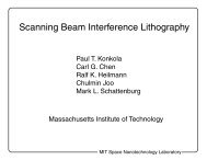
Design and analysis of a Scanning Beam Interference Lithography ...
Design and analysis of a Scanning Beam Interference Lithography ...
Design and analysis of a Scanning Beam Interference Lithography ...

Create successful ePaper yourself
Turn your PDF publications into a flip-book with our unique Google optimized e-Paper software.
ptk-title-121202.eps<br />
<strong>Design</strong> <strong>and</strong> <strong>analysis</strong> <strong>of</strong> a <strong>Scanning</strong> <strong>Beam</strong><br />
<strong>Interference</strong> <strong>Lithography</strong> system for patterning<br />
gratings with nanometer-level distortions<br />
by<br />
Paul T. Konkola<br />
April 3, 2003<br />
Ph.D. Thesis Defense<br />
Department <strong>of</strong> Mechanical Engineering<br />
Massachusetts Institute <strong>of</strong> Technology<br />
Committee:<br />
Dr. Mark L. Schattenburg (Advisor)<br />
Pr<strong>of</strong>essor David L. Trumper (Chair)<br />
Pr<strong>of</strong>essor Alex<strong>and</strong>er H. Slocum<br />
MIT Space Nanotechnology Laboratory
Acknowledgments<br />
Committee: Dr. Mark L. Schattenburg (Advisor)<br />
Pr<strong>of</strong>essor David L. Trumper (Chair)<br />
Pr<strong>of</strong>essor Alex<strong>and</strong>er H. Slocum<br />
ptk-acknowledgements-121202.eps<br />
Carl Chen<br />
Ralf Heilmann, Bob Fleming, Ed Murphy, Chulmin Joo, Chi Chang,<br />
Craig Forest, Andy Lapsa, Juan Montoya, G.S. Pati, Yanxia Sun, Shi Yue,<br />
David Carter, Jimmy Carter, Jim Daley, Juan Ferrera, Todd Hastings,<br />
Dario Gil, Mike McGuirck, Mark Mondol, Euclid Moon, Tim Savas, Mike<br />
Walsh<br />
Space Nanotechnology Laboratory<br />
Nanostructures Laboratory, Pr<strong>of</strong> Henry Smith<br />
Sponsors: DARPA <strong>and</strong> NASA<br />
MIT Space Nanotechnology Laboratory
Research Objectives<br />
Develop interference lithography, gratings, <strong>and</strong> fiducial<br />
grids as metrological tools.<br />
Research <strong>and</strong> develop methods for patterning <strong>and</strong><br />
measuring gratings with nanometer-level phase errors<br />
over large areas (up to 300 mm diameter).<br />
ptk-objective-033103.eps<br />
MIT Space Nanotechnology Laboratory
Outline<br />
• Contributions<br />
• Motivation<br />
• System concept<br />
• System overview<br />
• Error sources<br />
• System performance <strong>and</strong> <strong>analysis</strong><br />
• Electronic architecture<br />
• Error budget summary<br />
• Conclusions<br />
• Q&A<br />
ptk-outline-033103.eps<br />
MIT Space Nanotechnology Laboratory
Contributions (I)<br />
MIT Space Nanotechnology Laboratory<br />
ptk-contributions-033103.eps<br />
• <strong>Design</strong>, <strong>analysis</strong>, <strong>and</strong> demonstration <strong>of</strong> the first patterning<br />
machine based on an interference image <strong>and</strong> a scanned<br />
substrate. The system can pattern <strong>and</strong> measure large-area<br />
gratings with nanometer-level repeatability.
Contributions (II)<br />
• Experimental results <strong>and</strong> models that enhance the<br />
underst<strong>and</strong>ing <strong>of</strong> ultra-precision patterning.<br />
• System <strong>of</strong> stage control <strong>and</strong> acousto-optic fringe<br />
locking that achieves fringe phase control to the limits<br />
<strong>of</strong> quantization <strong>and</strong> sampling rate.<br />
MIT Space Nanotechnology Laboratory<br />
ptk-contributions2-033103.eps
Moire<br />
camera<br />
<strong>Lithography</strong><br />
metrology<br />
Application <strong>of</strong> Fiducial Grids<br />
<strong>and</strong> Gratings to Metrology<br />
Reticle<br />
grating<br />
Wafer<br />
grating<br />
Stage encoders<br />
Linear<br />
Encoder<br />
Linear<br />
Encoder<br />
Read<br />
Head<br />
Encoder systems<br />
Grating<br />
direction<br />
Linear<br />
Encoder<br />
Linear<br />
Encoder<br />
Linear<br />
Encoder<br />
Linear<br />
Encoder<br />
Linear<br />
Encoder<br />
Wafer<br />
Stage<br />
Reticle<br />
Stage<br />
<strong>Beam</strong><br />
Control<br />
<strong>Scanning</strong><br />
E-beam<br />
Detector<br />
Scintillating<br />
Fiducial Grid<br />
E-beam Resist<br />
Substrate<br />
ptk-applications-032703.eps<br />
Reference for electron<br />
beam lithography<br />
Signal<br />
Processing<br />
Feedback<br />
Signal<br />
MIT Space Nanotechnology Laboratory<br />
t<br />
Pattern
Variable<br />
attenuator<br />
Mirror<br />
Traditional <strong>Interference</strong> <strong>Lithography</strong><br />
<strong>Beam</strong>splitter<br />
<strong>Beam</strong>splitter<br />
Spatial Filters<br />
Grating period, = λ<br />
2sinθ <br />
2θ<br />
Laser beam<br />
λ = 351.1 nm<br />
ptk-il-110901.eps<br />
Phase displacement actuator<br />
Substrate<br />
Phase error<br />
sensor<br />
Mirror<br />
MIT Space Nanotechnology Laboratory
ptk-distortion-111101.eps<br />
Phase Distortion <strong>of</strong> Interfered Spherical Waves<br />
<br />
<br />
y (mm)<br />
10<br />
8<br />
6<br />
4<br />
2<br />
0<br />
-2<br />
-4<br />
-6<br />
-8<br />
<br />
<br />
<br />
<br />
<br />
-10<br />
-10 -8 -6 -4 -2 0 2 4 6 8 10<br />
<br />
<br />
<br />
<br />
<br />
<br />
<br />
λ <br />
<br />
<br />
x (mm)<br />
MIT Space Nanotechnology Laboratory
Stage distance<br />
measuring<br />
interferometer<br />
<strong>Beam</strong> pick<strong>of</strong>f<br />
SBIL System Concept<br />
Mirror<br />
2<br />
Laser<br />
Phase<br />
error<br />
sensor<br />
Stage<br />
error<br />
+<br />
<br />
+<br />
Substrate<br />
Controller<br />
Phase<br />
displacement<br />
actuator<br />
Much smaller beams<br />
than traditional IL<br />
Air bearing<br />
XY stage<br />
ptk-sbil-110201.eps<br />
MIT Space Nanotechnology Laboratory<br />
G
Y direction<br />
X direction<br />
Grating <strong>Scanning</strong> Method<br />
<strong>Scanning</strong><br />
grating<br />
image<br />
Air-bearing<br />
XY stage<br />
Resistcoated<br />
substrate<br />
Intensity<br />
Overlapping scans closely approximate<br />
a uniform intensity distribution<br />
Intensity<br />
<strong>Scanning</strong> grating image<br />
Summed<br />
intensity <strong>of</strong><br />
scans 1-6<br />
Individual<br />
scan<br />
MIT Space Nanotechnology Laboratory<br />
X<br />
ptk-scanmethod-040203.eps<br />
Grating<br />
period, Λ<br />
X
<strong>Scanning</strong> Electron Micrograph <strong>of</strong> a SBIL<br />
Written Grating<br />
Λ = 400 nm<br />
Silicon<br />
Resist<br />
ARC<br />
Definition <strong>of</strong> grating phase: φ(x 1 ) - φ(x 0 ) = 2 π!<br />
1<br />
Λ(x) dx<br />
ptk-semlines-032803.eps<br />
MIT Space Nanotechnology Laboratory<br />
x 0<br />
x 1<br />
x
Metrology block with<br />
phase measurement<br />
optics<br />
Wafer<br />
Chuck<br />
X-Y air bearing<br />
stage<br />
Front <strong>of</strong> System<br />
Receiving tower<br />
for UV laser<br />
(λ = 351.1 nm)<br />
MIT Space Nanotechnology Laboratory<br />
ptk-frontsystem-032703.eps<br />
Optical bench with<br />
interference lithography<br />
optics<br />
Refractometer<br />
interferometer<br />
X-axis interferometer<br />
Granite base<br />
Isolation system
SBIL Environmental Enclosure<br />
Environmental parameters: Temperature<br />
Pressure<br />
Humidity<br />
Particles<br />
Acoustics<br />
Air H<strong>and</strong>lers<br />
Chamber<br />
MIT Space Nanotechnology Laboratory<br />
ptk-enclosure-032903.eps
SBIL <strong>Beam</strong> Conditioning Optics<br />
ptk-beamconditioning-033003.eps<br />
Optical parameters: polarization, beam size, wavefront curvature, power<br />
λ/2 plate<br />
Polarizer<br />
Spatial<br />
filter <strong>and</strong><br />
collimating<br />
assembly<br />
AOM AOM<br />
+1/-1 order grating<br />
Camera<br />
UV Laser<br />
MIT Space Nanotechnology Laboratory
SBIL Alignment Optics<br />
Set interference angle for desired image period: Λ= λ<br />
2sinθ<br />
Picomotor<br />
driven<br />
mirrors<br />
Alignment splitter<br />
2θ<br />
AOM's shutter<br />
beams<br />
<strong>Beam</strong><br />
overlap<br />
PSD<br />
From<br />
splitter<br />
UV Laser<br />
Angle<br />
PSD<br />
Position<br />
PSD<br />
0 <strong>and</strong> -1 order reflections<br />
from grating on chuck<br />
MIT Space Nanotechnology Laboratory<br />
ptk-alignment-033003.eps
Period Measurement <strong>and</strong> <strong>Beam</strong> Alignment<br />
L R<br />
Photodiode<br />
Stage<br />
Motion<br />
⇒<br />
<strong>Beam</strong>splitter<br />
Mounted on Stage<br />
Grating Period Λ = D/N<br />
D = Distance Travelled<br />
by the Stage<br />
N Fringes<br />
MIT Space Nanotechnology Laboratory<br />
Xcc_PM_BA.eps<br />
<strong>Interference</strong> signal detected at<br />
the photodiode as stage moves.
Stage<br />
Control<br />
DSP<br />
System<br />
Frequency<br />
Synthesizer<br />
AOM2<br />
AOM1<br />
f = 100Mhz<br />
2<br />
f = 100Mhz<br />
1<br />
PM2<br />
Wafer<br />
X-Y Stage<br />
PM1<br />
AOM3<br />
f = 120Mhz<br />
3<br />
Writing Mode<br />
Fringe locking error<br />
ptk-writing-033003.eps<br />
x fle = (PM1 - PM2)Λ/p - x die<br />
{<br />
Phase instability<br />
above pick <strong>of</strong>f<br />
Displacement interferometer<br />
error perpendicular to fringes<br />
Λ: image period<br />
p: phase meter counts per period<br />
MIT Space Nanotechnology Laboratory
DSP<br />
System<br />
AOM2<br />
AOM1<br />
f = 90Mhz<br />
2<br />
f = 110Mhz<br />
1<br />
Reflected 0 order<br />
<strong>and</strong> diffracted -1<br />
order<br />
PM4<br />
Stage<br />
Control<br />
Frequency<br />
Synthesizer<br />
PM3<br />
Grating<br />
X-Y Stage<br />
(b) Reading Mode<br />
Reading Mode<br />
Unobservable error<br />
ptk-reading-033003.eps<br />
x ue = PM4 Λ/p - PM3 Λ/p - x die<br />
{<br />
Fringe-to-grating motion<br />
{<br />
Phase instability<br />
above pick <strong>of</strong>f<br />
Displacement interferometer<br />
error perpendicular to fringes<br />
Λ: image period<br />
p: phase meter counts per period<br />
MIT Space Nanotechnology Laboratory
Acousto-Optic<br />
Modulator No.3<br />
(AOM3)<br />
(AOM2)<br />
Spatial Filter<br />
Assembly for<br />
Left Arm<br />
Collimating Lens<br />
for Left Arm<br />
Metrology Block with<br />
Heterodyne Phase<br />
Measurement Optics<br />
<strong>Beam</strong> Pick<strong>of</strong>f<br />
Window<br />
Super-Invar<br />
Chuck<br />
{<br />
Front Optics<br />
Metrology Grating<br />
<strong>Beam</strong> Diverting Mirror<br />
Laser (λ=351.1 nm)<br />
MIT Space Nanotechnology Laboratory<br />
ptk-frontoptics-032703.eps<br />
Polarizer<br />
Position PSD<br />
Angle PSD<br />
CCD Camera<br />
Neutral Density<br />
Filters<br />
HeNe Stage<br />
Interferometer<br />
Laser (Thermally<br />
Enclosed)<br />
X-Axis Stage<br />
Interferometer
A A<br />
Stage <strong>and</strong> <strong>Lithography</strong> Metrology<br />
Phase sensing<br />
optics, 4-in-1<br />
monolithic splitter<br />
<strong>Beam</strong> pick<strong>of</strong>f<br />
Chuck<br />
Y interferometer<br />
Column<br />
reference<br />
Section A-A<br />
MIT Space Nanotechnology Laboratory<br />
ptk-metrology-032903.eps<br />
HeNe laser<br />
X, θ column<br />
reference<br />
interferometers
(Chuck)<br />
Nominally zero CTE<br />
mount assemblies
Super invar chuck<br />
flexure mounted<br />
to stage<br />
Super invar<br />
mounts for optics<br />
Zerodur mirrors<br />
bonded to chuck<br />
Metrology Frames<br />
Zerodur metrology block flexure<br />
mounted to bench, super invar<br />
inserts<br />
ptk-metrologyframes-032903.eps<br />
Refractometer<br />
cavity, bonded<br />
mirrors<br />
x-axis column<br />
reference mirror<br />
MIT Space Nanotechnology Laboratory
ptk-chucksys-032903.eps<br />
SBIL Chuck System with Metrology References<br />
<strong>Beam</strong> overlap<br />
position sensitive<br />
detector (PSD)<br />
Period measurement<br />
beamsplitter<br />
Reference grating<br />
for length scale<br />
calibration<br />
Wafer chuck compatible<br />
with 100 mm, 150mm,<br />
200 mm <strong>and</strong> 300 mm<br />
diameter wafers<br />
Interferometer mirrors<br />
MIT Space Nanotechnology Laboratory
SBIL Chuck System<br />
Performance issues:<br />
1) Heat sink<br />
2) Thermally stable<br />
3) Vibration sensitivity<br />
4) Repeatable substrate clamping distortions<br />
5) Critical metrology frame alignments<br />
6) Light weight<br />
Mirror<br />
alignment<br />
mounts (6X)<br />
Flexures (3X)<br />
Alignment <strong>and</strong> bonding features<br />
Theaded hole for<br />
leveling screw (3X)<br />
MIT Space Nanotechnology Laboratory<br />
ptk-chuck-032903.eps<br />
Epoxy injection<br />
ports (8X)
Ducts from AOM's<br />
Air flow paths<br />
ULPA filters<br />
Air h<strong>and</strong>ler B Air h<strong>and</strong>ler A<br />
ptk-airflow-033103.eps<br />
MIT Space Nanotechnology Laboratory
Left<br />
beam<br />
Substrate<br />
System Errors<br />
2θ<br />
<strong>Interference</strong><br />
pattern<br />
x s<br />
x d<br />
x f<br />
Right<br />
beam<br />
Column<br />
mirror<br />
Stage<br />
mirror<br />
Errors by subsystems Errors by physics<br />
• Displacement interferometer (x d)<br />
• Fringe locking interferometer (x f)<br />
• Metrology-block frame(x f)<br />
• Substrate frame (x s)<br />
• Rigid body motions (x s <strong>and</strong> x f)<br />
• Period Control<br />
• Image Distortion<br />
ptk-errors-033003.eps<br />
• Thermal expansion<br />
• Air index, wavelength<br />
• Interferometric periodic<br />
• Electronic<br />
• Vibration<br />
• Substrate clamping distortion<br />
• Control<br />
MIT Space Nanotechnology Laboratory
Gain, Dose error/ phase error<br />
10 0<br />
10 -1<br />
10 -2<br />
10 -3<br />
10 -1 10 -4<br />
Dose error transfer functions<br />
10 0<br />
¥<br />
Dose = ! Intensity(t) dt<br />
-¥<br />
f n<br />
Moving average (slit illumination)<br />
Envelope<br />
Gaussian weighted average (SBIL)<br />
10 1<br />
f n<br />
ptk-doseerror-033003.eps<br />
Moving average,<br />
decade/decade roll <strong>of</strong>f<br />
f n<br />
Gaussian filter has<br />
very fast cut <strong>of</strong>f.<br />
= f τ, slit illumination<br />
where<br />
τ = integration time<br />
= 0.8 f d/v, Gaussian<br />
MIT Space Nanotechnology Laboratory
Gain, Dose error/ phase error<br />
10 0<br />
10 -1<br />
10 -2<br />
10 -3<br />
10 -1 10 -4<br />
Dose error transfer functions<br />
10 0<br />
¥<br />
Dose = ! Intensity(t) dt<br />
-¥<br />
f n<br />
Moving average (slit illumination)<br />
Envelope<br />
Gaussian weighted average (SBIL)<br />
10 1<br />
f n<br />
ptk-doseerror-033003.eps<br />
Moving average,<br />
decade/decade roll <strong>of</strong>f<br />
f n<br />
Gaussian filter has<br />
very fast cut <strong>of</strong>f<br />
= f τ, slit illumination<br />
where<br />
τ = integration time<br />
= 0.8 f d/v, Gaussian<br />
MIT Space Nanotechnology Laboratory
Short Term Fringe-to-Substrate Stability<br />
Dose(x, y) = B + A(y) sin(2π(x -x4 (y))/Λ)<br />
where y = v t + yo Normalize dose amplitude<br />
error, eA (%)<br />
x 4 (nm)<br />
6<br />
-0.01<br />
-0.015<br />
-0.02<br />
-0.025<br />
Fringe-to-Substrate Stability<br />
4<br />
2<br />
0<br />
-2<br />
-4<br />
-6<br />
0 0.5 1 1.5 2 2.5 3 3.5 4<br />
Time (s), Timer period=0.1 ms.<br />
-0.03<br />
0 0.5 1 1.5 2 2.5 3 3.5 4<br />
Time (s), Timer period=0.1 ms.<br />
MIT Space Nanotechnology Laboratory<br />
ptk-shorttermx4-033103.eps<br />
x 4 raw, 3σ=3.89 nm<br />
x 4 , 3σ=1.94 nm, d/v=0.02 s<br />
Estimated Dose Amplitude Error Due to Phase Jitter<br />
-0.005
DSP<br />
System<br />
AOM2<br />
AOM1<br />
f = 90Mhz<br />
2<br />
f = 110Mhz<br />
1<br />
Reflected 0 order<br />
<strong>and</strong> diffracted -1<br />
order<br />
PM4<br />
Stage<br />
Control<br />
Frequency<br />
Synthesizer<br />
PM3<br />
Grating<br />
X-Y Stage<br />
(b) Reading Mode<br />
Reading Mode<br />
Unobservable error<br />
ptk-reading-033003.eps<br />
x ue = PM4 Λ/p - PM3 Λ/p - x die<br />
{<br />
Fringe-to-grating motion<br />
{<br />
Phase instability<br />
above pick <strong>of</strong>f<br />
Displacement interferometer<br />
error perpendicular to fringes<br />
Λ: image period<br />
p: phase meter counts per period<br />
MIT Space Nanotechnology Laboratory
Short term unobservable error (x ue)<br />
Fringe-to-substrate stability is very close to the unobservable error<br />
for the Gaussian filtered data.<br />
x ue (nm)<br />
5<br />
4<br />
3<br />
2<br />
1<br />
0<br />
-1<br />
-2<br />
-3<br />
-4<br />
x ue raw, 3σ=3.34 nm<br />
x ue , 3σ=1.95 nm, d/v=20 ms<br />
-5<br />
0 0.5 1 1.5 2 2.5 3 3.5 4<br />
Time (s), Timer period=0.1 ms.<br />
MIT Space Nanotechnology Laboratory<br />
ptk-shorttermxue-033103.eps
x ue (nm)<br />
Unobservable error over 56 seconds<br />
5<br />
4<br />
3<br />
2<br />
1<br />
0<br />
-1<br />
-2<br />
-3<br />
-4<br />
x ue raw, 3σ=3.12 nm<br />
x ue , 3σ=2.12 nm, d/v=20 ms<br />
-5<br />
0 10 20 30 40 50<br />
Time (s), Resampled timer period=0.7 ms.<br />
Data b<strong>and</strong>limited from 0 to 714 Hz<br />
MIT Space Nanotechnology Laboratory<br />
ptk-midtermxue-033103.eps
ptk-xuepsd-033103.eps<br />
Power Spectral Density <strong>of</strong> the Unobservable Error<br />
Power spectrum <strong>of</strong> x ue (nm/sqrt(Hz))<br />
10 0<br />
10 -1<br />
10 -2<br />
60 Hz electrical, 3σ=1.1 nm<br />
for 59.5 Hz to 60.5 Hz.<br />
3σ=1.8 nm for 100 Hz to 714 Hz.<br />
Thermal expansion, 0 to ≈0.04 Hz.<br />
Vibrations<br />
x ue raw, 3σ=3.12 nm<br />
x ue , 3σ=2.12 nm, d/v=20 ms<br />
Air index nonuniformity, 3σ=2.3 nm for 0 Hz to 59.5 Hz.<br />
10<br />
0 100 200 300 400 500 600 700<br />
-3<br />
Frequency (Hz), resolution=0.35 Hz<br />
MIT Space Nanotechnology Laboratory
x ue compensated (nm)<br />
x ue uncompensated (nm)<br />
Refractometer<br />
(∆n/n), ppm<br />
MIT Space Nanotechnology Laboratory<br />
ptk-longtermxue-033103.eps<br />
Long term stability over one hour (0 to 1.4 Hz)<br />
2<br />
1<br />
0<br />
-1<br />
-2<br />
-5<br />
-10<br />
-15<br />
0 500 1000 1500 2000 2500 3000 3500<br />
Time (s), resampled timer period=360 ms.<br />
-20<br />
0 500 1000 1500 2000 2500 3000 3500<br />
0.1<br />
0.05<br />
0<br />
-0.05<br />
Unobservable error after refractometer compensation (3σ= 1.4 nm)<br />
Uncompensated unobservable errror.<br />
Time (s), resampled timer period=360 ms.<br />
Refractometer data<br />
-0.1<br />
0 500 1000 1500 2000 2500 3000 3500<br />
Time (s), resampled timer period=360 ms.<br />
Interferometer phase:<br />
φ =<br />
2π deadpath<br />
λ
Power Spectrum <strong>of</strong> Long Term Unobservable<br />
Error <strong>and</strong> Refractometer Data<br />
Power spectrums (nm)/sqrt(Hz)<br />
10 1<br />
10 0<br />
10 -1<br />
Thermal expansion<br />
0.7 nm, 3σ for 0 to 0.04 Hz.<br />
10 -2<br />
x ue uncompensated, 3σ= 8.3 nm<br />
x ue compensated, 3σ= 1.4 nm<br />
Refractometer correction, 3σ= 8.2 nm<br />
10 -1<br />
Refractometer correction<br />
effective up to 0.04 Hz.<br />
Frequency (Hz), resolution=0.0027Hz<br />
10 0<br />
ptk-refracpsd-033103.eps<br />
MIT Space Nanotechnology Laboratory
Refractometer (∆n/n), ppm<br />
x ue (nm)<br />
10<br />
5<br />
0<br />
-5<br />
Refractometer calibration<br />
-10<br />
0 20 40 60 80 100 120<br />
Time (s), resampled timer period=12 ms.<br />
-0.04<br />
-0.06<br />
-0.08<br />
-0.1<br />
-0.12<br />
-0.14<br />
-0.16<br />
Stage x position: 0.12 m<br />
Calculated refractometer coefficient: 107 nm/ppm<br />
Inner door<br />
opened<br />
Outer door<br />
opened<br />
x ue uncompensated<br />
x ue compensated<br />
Outer door<br />
closed<br />
Inner door<br />
closed<br />
-0.18<br />
0 20 40 60 80 100 120<br />
Time (s), resampled timer period=12 ms.<br />
MIT Space Nanotechnology Laboratory<br />
ptk-refraccalib-033103.eps
Refractometer coefficient<br />
(nm/ppm)<br />
Refractometer coefficient<br />
error from fit (nm/ppm)<br />
110<br />
100<br />
90<br />
80<br />
70<br />
60<br />
50<br />
Refractometer performance<br />
Refractometer calibration data<br />
40<br />
0.12 0.13 0.14 0.15 0.16 0.17 0.18<br />
Stage x position (m)<br />
10<br />
5<br />
0<br />
Zero deadpath at x = 0.229 m<br />
-5<br />
2<br />
0.12 0.13 0.14 0.15 0.16 0.17 0.18<br />
Stage x position (m)<br />
data<br />
fit<br />
3.5<br />
2.5<br />
MIT Space Nanotechnology Laboratory<br />
3<br />
ptk-refraccoef-033103.eps<br />
Refractometer coefficient error is attributed to refractometer periodic error.<br />
Residual error increases as sqrt(deadpath).<br />
x ue after compensation<br />
(3σ, nm)
x fle (nm)<br />
4<br />
3<br />
2<br />
1<br />
0<br />
-1<br />
-2<br />
-3<br />
Fringe locking error (x fle)<br />
Raw data, µ = -0.01, 3 σ=2.45 nm.<br />
Dose phase error µ = -0.01, 3 σ =0.35 nm, d/v = 10 ms.<br />
-4<br />
0 0.5 1 1.5 2 2.5 3 3.5 4 4.5 5<br />
time(s)<br />
ptk-fle-040103.eps<br />
MIT Space Nanotechnology Laboratory
Gain<br />
Phase (deg)<br />
10 4<br />
10 2<br />
10 0<br />
10 -2<br />
10 -4<br />
50<br />
0<br />
-50<br />
-100<br />
-150<br />
-200<br />
-250<br />
10 1<br />
10 1<br />
PMr<br />
10 2<br />
10 2<br />
Fringe locking control<br />
fr<br />
Σ G(z)<br />
fc<br />
H(z) P(zz )<br />
PMe<br />
Controller Synthesizer<br />
Zygo<br />
Digital<br />
Filter<br />
+<br />
-<br />
+ +<br />
Σ<br />
PMu<br />
-1<br />
-PM1<br />
f (Hz)<br />
f (Hz)<br />
10 3<br />
10 3<br />
1600 Hz Loop Transmission<br />
cross over<br />
Experimental loop transmission<br />
Chan2/Chan1 same data<br />
Zygo filter, 15 Khz B<strong>and</strong>width<br />
Synthesizer w/ discrete time effects<br />
Discrete time controller<br />
Sum <strong>of</strong> components<br />
ptk-fringecontrol-040103.eps<br />
MIT Space Nanotechnology Laboratory
Vibration <strong>and</strong> dynamic errors<br />
x1<br />
Stationary<br />
refererence<br />
for ω
x ue corrected for grating nonlinearity (nm)<br />
Unobservable error during a scan<br />
No noticeable increase in unobservable<br />
error during constant velocity scan.<br />
8<br />
6<br />
4<br />
2<br />
0<br />
-2<br />
-4<br />
Scan start Scan stop<br />
5nm/0.1 g vibration<br />
sensitivity for the chuck<br />
Constant velocity<br />
-6<br />
0 0.2 0.4 0.6 0.8 1 1.2 1.4 1.6 1.8 2<br />
time (s)<br />
y r -y o (m)<br />
Velocity<br />
ref (m/s)<br />
Acceleration<br />
ref (m/s 2 )<br />
0.08<br />
0.06<br />
0.04<br />
0.02<br />
0.05<br />
Stage Reference Pr<strong>of</strong>ile<br />
ptk-scan100-040103.eps<br />
0<br />
0 0.1 0.2 0.3 0.4 0.5 0.6 0.7 0.8 0.9 1<br />
0.1<br />
time(s)<br />
0<br />
0 0.1 0.2 0.3 0.4 0.5 0.6 0.7 0.8 0.9 1<br />
0.5<br />
0<br />
-0.5<br />
Scan length = 8cm<br />
Max velocity=<br />
0.1 m/s<br />
time(s)<br />
Max acceleration = 0.1g<br />
0 0.1 0.2 0.3 0.4 0.5 0.6 0.7 0.8 0.9 1<br />
time(s)<br />
MIT Space Nanotechnology Laboratory
X axis acceleration error (g's)<br />
Y axis acceleration error (g's)<br />
4<br />
2<br />
0<br />
x 10-3<br />
Stage acceleration errors<br />
X accel err, µ=-6.0e-8 g, 3σ=2.0e-3 g<br />
X accel err, d/v = 20 ms, 3σ=6.6e-5 g<br />
-2<br />
CV accelerations<br />
85 µg max. Static accelerations<br />
-4<br />
0 0.2 0.4 0.6 0.8 1<br />
25 µg max.<br />
1.2 1.4 1.6 1.8 2<br />
Time (s), Timer period=0.2 ms.<br />
4<br />
2<br />
0<br />
-2<br />
x 10-3<br />
CV accelerations<br />
240 µg max.<br />
Y accel err, µ=4.2e-8 g, 3σ=1.3e-3 g<br />
Y accel err, d/v = 20 ms, 3σ=3.6e-4 g<br />
Static accelerations<br />
15 µg max.<br />
-4<br />
0 0.2 0.4 0.6 0.8 1 1.2 1.4 1.6 1.8 2<br />
Time (s), Timer period=0.2 ms.<br />
Scan start<br />
Scan stop<br />
MIT Space Nanotechnology Laboratory<br />
ptk-stageaccel-040103.eps
X axis stage error (nm)<br />
Y axis stage error (nm)<br />
400<br />
300<br />
200<br />
100<br />
0<br />
-100<br />
-200<br />
Stage Error During the Scan<br />
-300<br />
0 0.2 0.4 0.6 0.8 1 1.2 1.4 1.6 1.8 2<br />
1000<br />
Time (s), Timer period=0.2 ms.<br />
Y axis<br />
500<br />
0<br />
-500<br />
-1000<br />
-1500<br />
X axis<br />
-2000<br />
0 0.2 0.4 0.6 0.8 1 1.2 1.4 1.6 1.8 2<br />
Time (s), Timer period=0.2 ms.<br />
ptk-stageerrr-040103.eps<br />
MIT Space Nanotechnology Laboratory
Power Spectrum (units/Hz 1/2 )<br />
Vibration Errors are Proportional to the<br />
Metrology Block Accelerations<br />
10 0<br />
10 -1<br />
10 -2<br />
1nm/1mg vibration sensitivity<br />
10<br />
100 150 200 250 300 350 400 450 500<br />
-3<br />
f (Hz)<br />
X acceleration (mg/rtHz)<br />
x ue (nm/rtHz)<br />
MIT Space Nanotechnology Laboratory<br />
ptk-xerrxuepsd-040103.eps
Power spectrum <strong>of</strong><br />
x (nm/sqrt(Hz)<br />
nl<br />
Ratio <strong>of</strong> Power spectrums.<br />
moving/stationary<br />
10 0<br />
10 -1<br />
10 -2<br />
Power spectrum <strong>of</strong> unobservable error<br />
for a static stage <strong>and</strong> a slow scan<br />
Static stage<br />
stage moving at 127 µm/s<br />
10<br />
0 500 1000 1500 2000 2500 3000 3500 4000 4500 5000<br />
-3<br />
Frequency (Hz), resolution=2.44 Hz<br />
Ratio <strong>of</strong> power spectrums for moving stage/stationary stage<br />
10 2<br />
10 1<br />
10 0<br />
Error removed from low frequencies.<br />
10<br />
0 500 1000 1500 2000 2500 3000 3500 4000 4500 5000<br />
-1<br />
630 Hz 800 Hz 1260 Hz 1600 Hz<br />
Frequency (Hz), resolution=2.44 Hz<br />
ptk-nonlinearityratios-040103.eps<br />
x phase meter<br />
fundamental at<br />
800 Hz<br />
(=4 (127µm/s)/(.633µm))<br />
PM4 fundamental at<br />
315 Hz<br />
(=(127µm/s)/(.401µm))<br />
MIT Space Nanotechnology Laboratory
ptk-periodicpmx-040103.eps<br />
Periodic error <strong>of</strong> x axis interferometer (±0.6nm P-V)<br />
Periodic error (nm)<br />
0.6<br />
0.4<br />
0.2<br />
0<br />
-0.2<br />
-0.4<br />
-0.6<br />
-0.8<br />
Experimental data<br />
Reconstruction using DC <strong>and</strong> first two harmonics<br />
0 50 100 150 200 250 300 350 400 450 500<br />
mod(PM x , p) (counts)<br />
MIT Space Nanotechnology Laboratory
ptk-periodicpm4-040103.eps<br />
Periodic error <strong>of</strong> phase meter 4 interferometer<br />
(±0.4nm P-V)<br />
Periodic error (nm)<br />
0.6<br />
0.4<br />
0.2<br />
0<br />
-0.2<br />
-0.4<br />
-0.6<br />
Experimental data<br />
Reconstruction using DC, second, <strong>and</strong> fourth harmonics<br />
0 50 100 150 200 250 300 350 400 450 500<br />
mod(PM 4 , p) (counts)<br />
MIT Space Nanotechnology Laboratory
Power spectrum <strong>of</strong><br />
θ (µrad/sqrt(Hz)<br />
Ratio <strong>of</strong> Power spectrums.<br />
moving/stationary<br />
ptk-thetascanpsd-040103.eps<br />
Power spectrum <strong>of</strong> the theta interferometer<br />
for a static stage <strong>and</strong> a slow scan<br />
10 -1<br />
10 -2<br />
10 -3<br />
10 -4<br />
10<br />
0 500 1000 1500 2000 2500 3000 3500 4000 4500 5000<br />
-5<br />
Frequency (Hz), resolution=2.44 Hz<br />
10 2<br />
10 1<br />
10 0<br />
Stationary stage<br />
stage moving at 127 µm/s<br />
Ratio <strong>of</strong> power spectrums for moving stage/stationary stage<br />
Periodic error observed when there is no OPD change!<br />
10<br />
0 500 1000 1500 2000 2500 3000 3500 4000 4500 5000<br />
Frequency (Hz), resolution=2.44 Hz<br />
-1<br />
400 Hz 800 Hz 1600 Hz<br />
MIT Space Nanotechnology Laboratory
ptk-waferphasemap-012103.eps<br />
Wafer phase mapping repeatability (2.9 nm, 3σ)<br />
5<br />
4<br />
3<br />
2<br />
1<br />
0<br />
-1<br />
-2<br />
-3<br />
60<br />
-4<br />
50<br />
40<br />
30<br />
20<br />
y (mm)<br />
10<br />
0<br />
0<br />
20<br />
40<br />
x (mm)<br />
60<br />
MIT Space Nanotechnology Laboratory<br />
80<br />
4<br />
3<br />
2<br />
1<br />
0<br />
-1<br />
-2<br />
-3
MIT Space Nanotechnology Laboratory<br />
ptk-readingmapcontf-040103.eps<br />
Nonlinearity <strong>of</strong> a grating written by SBIL<br />
0 10 20 30 40 50 60<br />
0<br />
10<br />
20<br />
30<br />
40<br />
50<br />
x (mm)<br />
y (mm)<br />
x nl (nm)<br />
-5<br />
-5<br />
-5<br />
-2.5<br />
-2.5<br />
-2.5<br />
-2.5<br />
-2.5<br />
-2.5<br />
-2.5<br />
0<br />
0<br />
0<br />
0<br />
0<br />
0<br />
0<br />
0<br />
0 0<br />
0<br />
0<br />
0<br />
0<br />
0<br />
0<br />
0<br />
0<br />
0<br />
0 0<br />
0<br />
0<br />
0<br />
0<br />
0<br />
0<br />
0<br />
0<br />
0<br />
0<br />
0<br />
0<br />
0<br />
0<br />
0<br />
0<br />
0<br />
2.5<br />
2.5<br />
2.5<br />
2.5<br />
2.5<br />
2.5<br />
2.5<br />
2.5<br />
0<br />
0<br />
0<br />
0<br />
0<br />
0<br />
0<br />
-2.5<br />
-2.5<br />
-2.5<br />
-2.5<br />
-2.5<br />
-2.5<br />
-2.5<br />
-2.5<br />
-2.5<br />
-2.5<br />
0<br />
0<br />
0<br />
0<br />
0<br />
2.5<br />
2.5<br />
2.5<br />
2.5<br />
2.5<br />
2.5<br />
2.5<br />
2.5<br />
0<br />
0<br />
0 0<br />
0<br />
2.5<br />
2.5<br />
5<br />
5<br />
-2.5<br />
-2.5<br />
-2.5<br />
2.5<br />
2.5<br />
2.5<br />
2.5<br />
2.5<br />
2.5<br />
2.5<br />
-2.5<br />
-2.5<br />
-2.5<br />
2.5<br />
2.5<br />
2.5<br />
2.5<br />
2.5<br />
-2.5<br />
5<br />
-5<br />
-5<br />
2.5<br />
5<br />
2.5<br />
-2.5<br />
-2.5<br />
2.5<br />
-5<br />
2.5<br />
5<br />
-7.5<br />
-2.5<br />
0<br />
0<br />
0<br />
-2.5<br />
-5<br />
2.5<br />
7.5<br />
-2.5<br />
2.5<br />
-2.5<br />
5<br />
-7.5<br />
5<br />
-10<br />
2.5<br />
-2.5<br />
5<br />
0<br />
7.5<br />
5<br />
5<br />
-2.5<br />
0<br />
5<br />
10<br />
-10<br />
0<br />
2.5<br />
-2.5<br />
-2.5<br />
0<br />
7.5<br />
2.5<br />
2.5<br />
2.5<br />
5<br />
-5<br />
5<br />
-5<br />
-2.5<br />
-2.5<br />
5<br />
2.5<br />
5<br />
2.5<br />
-2.5<br />
-5<br />
-5<br />
5<br />
2.5<br />
0<br />
-2.5<br />
2.5<br />
7.5<br />
-2.5<br />
-5<br />
0<br />
-2.5<br />
-2.5<br />
0<br />
5<br />
0<br />
-5<br />
0<br />
0<br />
-5<br />
2.5<br />
2.5<br />
2.5<br />
7.5<br />
5<br />
0<br />
-2.5<br />
2.5<br />
-2.5<br />
2.5<br />
-5<br />
0<br />
-5<br />
0<br />
5<br />
7.5<br />
5<br />
0<br />
2.5<br />
7.5<br />
5<br />
0<br />
-5<br />
5<br />
5<br />
10<br />
2.5<br />
7.5<br />
5<br />
5<br />
7.5<br />
0<br />
-5<br />
5<br />
2.5<br />
5<br />
0<br />
5<br />
2.5<br />
0<br />
2.5<br />
-5<br />
-5<br />
2.5<br />
-2.5<br />
5<br />
5<br />
7.5<br />
5<br />
0<br />
0<br />
0<br />
0<br />
2.5<br />
0<br />
-5<br />
2.5<br />
-5<br />
-5<br />
0<br />
-5<br />
0<br />
2.5<br />
5<br />
-5<br />
5<br />
-5<br />
5<br />
5<br />
-5<br />
5<br />
5<br />
-5<br />
5<br />
5<br />
5<br />
-5<br />
5<br />
0<br />
-5<br />
-5<br />
-5<br />
0<br />
5<br />
0<br />
0<br />
5<br />
5<br />
0<br />
5<br />
5<br />
5<br />
0<br />
0<br />
0<br />
0<br />
5<br />
0<br />
0<br />
0<br />
0<br />
5<br />
0<br />
0<br />
0<br />
0<br />
0<br />
5<br />
5<br />
0<br />
0<br />
5<br />
0<br />
5<br />
5<br />
0<br />
0<br />
5<br />
0<br />
0<br />
0<br />
5<br />
0<br />
0<br />
5<br />
0<br />
Particle defects<br />
Particle defects
y (mm)<br />
y (mm)<br />
25<br />
24<br />
23<br />
22<br />
21<br />
20<br />
19<br />
18<br />
17<br />
16<br />
15<br />
-5<br />
-5<br />
-10<br />
-10<br />
-15<br />
-15<br />
-20<br />
-5<br />
Errors Caused by Particles Between<br />
the Wafer <strong>and</strong> the Chuck<br />
-5<br />
-20<br />
-10<br />
-10<br />
-5<br />
-15<br />
-5<br />
43 44 45 46 47 48 49 50 51<br />
42 52<br />
x (mm)<br />
Calculated out-<strong>of</strong>-plane distortion (nm)<br />
25<br />
24<br />
23<br />
22<br />
21<br />
20<br />
19<br />
18<br />
17<br />
16<br />
15<br />
0<br />
0<br />
0<br />
0<br />
0<br />
42<br />
Grating nonlinearity (nm)<br />
0<br />
0<br />
50<br />
0<br />
100<br />
50<br />
150<br />
50<br />
200<br />
100<br />
0<br />
150<br />
250<br />
200<br />
0<br />
0<br />
5<br />
0 0<br />
100<br />
250<br />
10<br />
0<br />
5<br />
0<br />
20<br />
43 44 45 46 47 48 49 50 51<br />
200<br />
150<br />
x (mm)<br />
150<br />
50<br />
15<br />
15<br />
100<br />
0<br />
10<br />
10<br />
5<br />
0<br />
-5<br />
5<br />
100<br />
0<br />
100<br />
150<br />
50<br />
0<br />
0<br />
-5<br />
0<br />
0<br />
52<br />
ptk-particles-040103.eps<br />
White light interferogram formed between<br />
a quartz wafer <strong>and</strong> the chuck<br />
Rings around a particle<br />
MIT Space Nanotechnology Laboratory
Analog Input:<br />
Power Sensors.<br />
Sensors, general.<br />
D/A PMC<br />
A/D PMC<br />
IXC6 Master/<br />
DSP/Power PC<br />
Analog Output:<br />
Stage Linear Amplifiers<br />
Vibration Isolation Feedforward.<br />
Analog Test Points.<br />
PC<br />
Host<br />
ZMI 2002<br />
VME Bus<br />
ZMI 2002<br />
Control Architecture<br />
Realtime Control Platform LabVIEW-Based I/O<br />
ZMI 2002<br />
ZMI 2002<br />
VME Rack<br />
Digital Change<br />
<strong>of</strong> State Board<br />
TTL Digital<br />
Input/Output<br />
TTL Digital<br />
Input/Output<br />
ZMI 2001<br />
Refractometer.<br />
<strong>Lithography</strong><br />
Interferometers<br />
Stage<br />
Interferometers<br />
Power<br />
Supply<br />
Stage Position Limits<br />
Air-bearing Pressure Limit<br />
LabVIEW PC Control Lines<br />
Digital Frequency<br />
Sythesizer<br />
Reference clock from Zygo laser<br />
Comm. to LabVIEW PC<br />
Acousto-Optic<br />
Modulators<br />
NI IMAQ 1424<br />
Frame Grabber<br />
NI PCI-DIO-96<br />
Digital I/O<br />
NI 6034E<br />
Analog I/O<br />
NI 6034E<br />
Analog I/O<br />
MIT Space Nanotechnology Laboratory<br />
PC<br />
Internal PCI Bus<br />
Position Sensing<br />
Detectors<br />
Picomotor Driver<br />
Communication to<br />
IXC6.<br />
Picomotors<br />
ptk-controlarch-040103.eps<br />
Wavefront<br />
Metrology<br />
CCD
VMIVME-1181-000,<br />
32bit digital change-<strong>of</strong>-state<br />
input board.<br />
VMIVME-2510B,<br />
64bit TTL digital output I/O<br />
VMIVME-2510B,<br />
64bit TTL digital output I/O<br />
ZMI 2001, Interferometer<br />
Card, 1 axis<br />
ZMI 2002, Interferometer<br />
Card, 2 axes<br />
ZMI 2002, Interferometer<br />
Card, 2 axes<br />
ZMI 2002, Interferometer<br />
Card, 2 axes<br />
ZMI 2002, Interferometer<br />
Card, 2 axes<br />
SBIL Realtime Control Platform<br />
PC with Windows NT 4.0, Micron<br />
400 Mhz, Pentium II. 128 Mb DRAM<br />
Development tools: Code Composer<br />
Studio (TI), IXCtools (Ixthos),<br />
Tornado II (Wind River Systems).<br />
512 Kbytes<br />
SBSRAM<br />
83 Mhz<br />
PMC<br />
Site #1<br />
Ethernet<br />
Port<br />
DSP A<br />
C6701, 167 Mhz<br />
16 Mbytes<br />
SDRAM<br />
83MHz<br />
IXStar<br />
PCI - DSP<br />
Serial<br />
Port<br />
DSP B<br />
C6701, 167 Mhz<br />
512 Kbytes<br />
SBSRAM<br />
83 Mhz<br />
16 bit Host Port Bus<br />
Host Port<br />
Interface<br />
4 Mbytes<br />
Flash<br />
MPC 8240<br />
IOPlus<br />
250 Mhz<br />
64 Mbytes<br />
SDRAM<br />
100 Mhz<br />
32 Bit 32 Bit 32 Bit 32 Bit<br />
64 Bit PCI - PCI 64 Bit 66 MHz PCI - PCI<br />
64 Bit<br />
66 MHz Bridge<br />
Bridge 66 MHz<br />
PMC-16AO-12-2022,<br />
12 Channel, 16bit DA<br />
64 Bit, User<br />
Defined I/O<br />
to P0*<br />
16 Mbytes<br />
SDRAM<br />
83MHz<br />
XDS510<br />
ISA-JTAG emulator<br />
JTAG to<br />
DSP Chain<br />
64 Bit<br />
PCI - PCI<br />
Bridge<br />
33 MHz<br />
Universe II<br />
PCI-VMEbus<br />
VME64x Backplane<br />
(11 Mbytes/s)<br />
DSP C<br />
C6701, 167 Mhz<br />
512 Kbytes<br />
SBSRAM<br />
83 Mhz<br />
IXC6 Quad DSP Board<br />
16 Mbytes<br />
SDRAM<br />
83MHz<br />
IXStar<br />
PCI - DSP<br />
MIT Space Nanotechnology Laboratory<br />
ptk-052601-control.eps<br />
512 Kbytes<br />
SBSRAM<br />
83 Mhz<br />
PMC-16AIO-88-31,<br />
8 Channel, 16bit DA <strong>and</strong><br />
8 Channel, 16bit AD<br />
DSP D<br />
C6701, 167 Mhz<br />
64 Bit, User<br />
Defined I/O<br />
to P2<br />
16 Mbytes<br />
SDRAM<br />
83MHz<br />
PMC<br />
Site #2
Error Budget Summary*<br />
Errors by Subsystems<br />
Error Category<br />
Error<br />
budget,<br />
static<br />
[±nm]<br />
Error<br />
budget,<br />
worst case<br />
[±nm]<br />
Displacement interferometer 1.66 4.87<br />
Fringe locking interferometer 1.58 1.58<br />
Metrology block frame 0.51 0.51<br />
Substrate frame 0.40 2.79<br />
Rigid body error motions 0.12 0.12<br />
rss error 2.38 5.86<br />
Errors by Physics<br />
Error category<br />
Error<br />
budget,<br />
static<br />
[±nm]<br />
Error<br />
budget,<br />
worst case<br />
[±nm]<br />
Thermal expansion 0.68 2.46<br />
Air index 2.00 5.00<br />
Periodic error 1.02 1.02<br />
Electronic 0.12 0.12<br />
Vibration 0.08 0.08<br />
Substrate clamping distortion 0 1.41<br />
Control 0.40 0.40<br />
rss error 2.38 5.86<br />
*Assumes particle problem resolved. Does not include errors due to<br />
image distortion <strong>and</strong> period control.<br />
ptk-errorsummary-040103.eps<br />
MIT Space Nanotechnology Laboratory
Conclusions<br />
• I designed <strong>and</strong> analyzed the first patterning machine<br />
based on an interference image <strong>and</strong> a scanned<br />
substrate. I developed a method for patterning <strong>and</strong><br />
measuring gratings with nanometer level errors.<br />
• I described <strong>and</strong> applied the SBIL metrology system.<br />
The experimental results <strong>and</strong> models enhance the underst<strong>and</strong>ing<br />
<strong>of</strong> ultra-precision patterning.<br />
• Analysis suggests the following improvements:<br />
Improvements<br />
Error budget<br />
static [±nm]<br />
Error budget<br />
worst case [±nm]<br />
Error without improvements 2.38 5.86<br />
Error without thermal expansion <strong>and</strong> index<br />
terms 1.11 1.79<br />
Error without periodic term 2.15 5.77<br />
Error without thermal expansion, index, <strong>and</strong><br />
periodic terms 0.43 1.48<br />
• Application <strong>of</strong> self calibration techniques will lead to<br />
gratings with nanometer level accuracy.<br />
MIT Space Nanotechnology Laboratory<br />
ptk-conclusions-040103.eps