The Importance of Nanotechnology and Nanometrology for Space ...
The Importance of Nanotechnology and Nanometrology for Space ...
The Importance of Nanotechnology and Nanometrology for Space ...

Create successful ePaper yourself
Turn your PDF publications into a flip-book with our unique Google optimized e-Paper software.
<strong>The</strong> <strong>Importance</strong> <strong>of</strong> <strong>Nanotechnology</strong> <strong>and</strong> <strong>Nanometrology</strong><br />
<strong>for</strong> <strong>Space</strong> Instrumentation.<br />
MIT<br />
Mark L. Schattenburg<br />
Massachusetts Institute <strong>of</strong> Technology<br />
<strong>Space</strong> <strong>Nanotechnology</strong> Laboratory<br />
Center <strong>for</strong> <strong>Space</strong> Research<br />
<strong>Space</strong> Nano-technology Workshop<br />
Tsukuba <strong>Space</strong> Center<br />
National <strong>Space</strong> Development Agency <strong>of</strong> Japan<br />
Tsukuba, Japan<br />
November 27, 2001<br />
<br />
Massachusetts Institute <strong>of</strong> Technology
MIT<br />
MOTIVATION<br />
Goal <strong>of</strong> our laboratory: improve per<strong>for</strong>mance <strong>of</strong> astrophysics instrumentation.<br />
• Weak signals from space motivate ultra-sensitive instruments.<br />
High launch costs motivate highest per<strong>for</strong>mance with lowest possible mass.<br />
• Many useful phenomena occur when structure size <strong>and</strong> placement accuracy is below<br />
the wavelength <strong>of</strong> light, into the nanometer regime.<br />
• Nanostructures need special considerations to survive stress <strong>of</strong> space (launch vibration,<br />
heat/cold) <strong>and</strong> not be destroyed or lose dimensional accuracy. (Use size hierarchy <strong>and</strong><br />
kinematic mounting.)<br />
• Extreme need <strong>for</strong> high quality <strong>and</strong> manufacturability. <strong>Nanometrology</strong> is key to success<br />
<strong>for</strong> process control (interferometry, SEM <strong>and</strong> AFM).<br />
• Our lab has developed novel nanostructure technologies applied to nine NASA<br />
missions <strong>and</strong> others under development. Three missions are described:<br />
Ch<strong>and</strong>ra x-ray telescope.<br />
IMAGE mission neutral atom camera.<br />
Constellation X x-ray telescope mission development.<br />
<br />
Massachusetts Institute <strong>of</strong> Technology
MLS-01-03-14.02<br />
NASA Ch<strong>and</strong>ra Observatory X-ray Telescope<br />
Per<strong>for</strong>ms high-resolution x-ray imaging <strong>and</strong> spectroscopy in the<br />
energy range <strong>of</strong> 0.1-10 keV (wavelengths from 0.1 to 10 nanometers).<br />
Subrahmanyan<br />
Ch<strong>and</strong>rasekhar<br />
(1910-1995)<br />
Nobel Prize, 1983
CXC<br />
Ch<strong>and</strong>ra X-Ray Observatory<br />
Crab Nebula
cc_GrazingIncidence.ai<br />
θ c<br />
Principles <strong>of</strong> X-ray Optics at Grazing Incidence<br />
Refractive index <strong>for</strong> x-ray radiation:<br />
n(<br />
ω) = 1−<br />
δ ( ω)<br />
+ iβ<br />
( ω)<br />
where δ , β ∼<br />
Critical angle <strong>for</strong> total external reflection <strong>of</strong> x-rays:<br />
n = 1−<br />
δ + iβ<br />
θ<br />
Critical Ray<br />
Grazing Incidence Radiation <strong>and</strong><br />
Total External Reflection<br />
θ = 2δ<br />
c<br />
Totally<br />
Reflected<br />
Rays<br />
Reflectivity<br />
~10 -2<br />
1<br />
0.8<br />
0.6<br />
0.4<br />
0.2<br />
C<br />
A<br />
B<br />
D E<br />
0.5 1 1.5 2 2.5 3<br />
θ / θ c<br />
10 -4<br />
A : β / δ = 0<br />
B : β / δ = 10<br />
C : β / δ = 10<br />
D : β / δ = 1<br />
E : β / δ = 3<br />
−2<br />
−1
MLS-2001-05-23.01.eps<br />
X-rays<br />
Ch<strong>and</strong>ra Observatory Grazing Incidence Optics<br />
(Wolter Type I)<br />
Nested<br />
Hyperboloids<br />
Nested<br />
Paraboloids<br />
1.1 Meter Diameter<br />
Doubly-<br />
Reflected<br />
X-rays<br />
10 Meters<br />
Focal<br />
Plane
Ch<strong>and</strong>ra-Mirror.eps<br />
Ch<strong>and</strong>ra X-ray Telescope Mirror Assembly<br />
Raytheon Optical Systems & Eastman Kodak Corp.
HETGS<br />
NASA Ch<strong>and</strong>ra Observatory X-ray Telescope<br />
High Energy Transmission Grating Spectrometer (HETGS)<br />
Aspect Camera<br />
Stray Light Shade<br />
High Resolution<br />
Mirror Assembly<br />
(HRMA)<br />
Sunshade<br />
Door<br />
Thrusters (4)<br />
(105 lb)<br />
Low Gain<br />
Antenna (2)<br />
<strong>Space</strong>craft<br />
Module<br />
Transmission<br />
Gratings (2)<br />
Optical<br />
Bench<br />
Ch<strong>and</strong>ra Telescope<br />
X-rays<br />
X-ray<br />
mirrors<br />
P H<br />
Grating<br />
(in use)<br />
Solar Array (2)<br />
CCD Imaging<br />
Spectrometer<br />
(ACIS)<br />
High Resolution<br />
Camera (HRC)<br />
Integrated Science<br />
Instrument Module<br />
(ISIM)<br />
Grating<br />
(stowed)<br />
CCD1 CCD2 CCD3 CCD4 CCD5 CCD6<br />
HETGS Instrument<br />
X-ray CCD<br />
Detector array<br />
θ<br />
Zero-order beams<br />
Diffracted beams<br />
Rowl<strong>and</strong> Torus Transmission Grating Geometry <strong>and</strong> CCD Readout Array
MLS-2001-05-11.01eps<br />
NASA Ch<strong>and</strong>ra X-ray Observatory<br />
High Energy Transmission Grating Spectrometer (HETGS)<br />
HETGS instrument.<br />
1.1 meter<br />
Invar grating frame.<br />
3 cm<br />
Scanning electron micrograph <strong>of</strong> gold grating.<br />
100 nm<br />
550 nm
MLS-1994-02-16.eps<br />
Bacterium<br />
130 nm<br />
Advanced<br />
Commercial Chip<br />
(MOS Transistor)<br />
λ~500 nm<br />
Visible Light<br />
21,000X Magnification<br />
Human<br />
Chromosome Human Hair<br />
(~50 µm diam.)<br />
100 nm<br />
Ch<strong>and</strong>ra X-ray<br />
Transmission Grating
MLS-2001-05-24.01.eps<br />
0.6 µm<br />
1.0 µm<br />
Pi-Phase-Shifting Transmission Grating Design<br />
100 nm<br />
polyimide<br />
gold<br />
grating<br />
polyimide<br />
membrane<br />
Transmission Grating Design<br />
adhesive<br />
Invar<br />
frame<br />
5 nm Chrome<br />
20 nm Gold<br />
x rays<br />
φ i<br />
φ bar - φ space ~π<br />
gold<br />
bars<br />
Bars shift phase x-rays by ~π<br />
zero order ~0<br />
first order maximized
Capella-2.eps<br />
Ch<strong>and</strong>ra Observatory X-ray Spectrum <strong>of</strong> Binary Star Capella<br />
Counts/Bin<br />
100<br />
50<br />
0<br />
0.5<br />
Raw x-ray spectra.<br />
1.0<br />
λ/∆λ=<br />
1000<br />
1.5<br />
X-ray Wavelength (nanometers)<br />
2.0
E0102-72.eps<br />
Ch<strong>and</strong>ra X-ray Spectrum<br />
Small Magellanic Cloud Supernova Remant E0102-72<br />
Direct X-ray Image (CCD Camera)<br />
longer wavelengths <br />
shorter wavelengths<br />
X-ray Image Dispersed by Transmission Gratings<br />
Zero<br />
Order
MLS-99-05-26.03<br />
mirror<br />
variable<br />
attenuator<br />
beamsplitter<br />
p = λ<br />
2 sinθ<br />
Interference Lithography<br />
beamsplitter<br />
spatial filters<br />
2θ<br />
Pockels cell<br />
substrate<br />
laser beam<br />
λ = 351.1 nm<br />
phase error<br />
sensor<br />
mirror
MLS-94-05-13.01<br />
15 nm<br />
Ta 2 O 5<br />
0.5-1.0 µm<br />
ARC<br />
5 nm chromium<br />
20 nm gold<br />
200 nm<br />
resist<br />
0.5-1.0 µm<br />
polyimide µ<br />
d<br />
silicon wafer<br />
silicon<br />
(a) Prepare substrate.<br />
polyimide<br />
Membrane-Supported Transmission Grating<br />
Fabrication Process - Macro View<br />
(b) Pattern gold grating.<br />
gold<br />
grating<br />
(c) Acid spin-etch wafer<br />
backside.<br />
adhesive<br />
(d) Bond to Invar frame.<br />
(e) Cut away.<br />
silicon<br />
Invar<br />
frame
MLS-94-05-13.02<br />
resist<br />
ARC<br />
polyimide<br />
silicon<br />
ARC<br />
polyimide<br />
silicon<br />
(b) Pattern by IL<br />
<strong>and</strong> develop.<br />
Membrane-Supported Transmission Grating<br />
Fabrication Process - Micro View<br />
(a) Prepare<br />
substrate.<br />
interlayer<br />
plating<br />
base<br />
ARC<br />
polyimide<br />
silicon<br />
(c) Etch interlayer in<br />
CF 4 RIE plasma.<br />
polyimide<br />
silicon<br />
(d) Etch ARC in O 2<br />
RIE plasma.<br />
plated gold<br />
polyimide<br />
silicon<br />
(e) Gold electroplate.<br />
plated<br />
gold<br />
polyimide<br />
silicon<br />
(f) Strip interlayer<br />
<strong>and</strong> ARC.<br />
polyimide<br />
epoxy<br />
Invar<br />
(g) Acid spin-etch<br />
substrate.<br />
Align <strong>and</strong> bond<br />
to frames.
MLS-2001-05-25.02.eps<br />
Reflectivity from Resist/IL Boundary<br />
0.5<br />
0.4<br />
0.3<br />
0.2<br />
0.1<br />
0<br />
Gold Transmission Grating Fabrication Process<br />
Benefit <strong>of</strong> anti-reflection coating (ARC).<br />
Resist<br />
ARC<br />
Silicon<br />
Ta 2 O 5<br />
200 nm period<br />
λ = 351.1. nm<br />
TE polarization<br />
0 200 400 600 800<br />
ARC Thickness (nm)<br />
Grating after oxygen plasma RIE <strong>of</strong> ARC.<br />
100 nm<br />
600 nm<br />
Grating after interference lithography.<br />
100 nm<br />
Grating after gold plating <strong>and</strong> resist stripping.<br />
100 nm<br />
resist<br />
ARC<br />
Ta 2 O 5
IMAGE.eps<br />
NASA Imager <strong>for</strong> Magnetopause-to-Aurora<br />
Global Exploration Mission (IMAGE)<br />
Medium Energy<br />
Neutral Atom Detector (MENA)
Magnetosphere-2.eps<br />
Earth’s <strong>Space</strong> Environment: <strong>The</strong> Magnetosphere<br />
<strong>Space</strong> Weather
Charge-Exchange-2<br />
TRAPPED<br />
A magnetically trapped ion captures<br />
an electron from a neutral<br />
hydrogen atom...<br />
Charge Exchange<br />
FREE<br />
...creating an energetic neutral atom<br />
(ENA) that is no longer trapped.
MENA-Concept-2.eps<br />
D 1<br />
START Foil<br />
2.6 nm Carbon<br />
STOP<br />
MENA Neutral Atom Camera<br />
Measurement Concept<br />
Collimator HWHM:<br />
±55º imaging plane<br />
±2º spin plane<br />
UV<br />
Nan<strong>of</strong>ilters<br />
Ionized Atom<br />
X 1<br />
α<br />
Ground<br />
Grid<br />
Primary MENA<br />
Accelerating<br />
Grid<br />
START Electrons<br />
tan(α) = X 2 - X 1<br />
L<br />
tan(δα) = cos(α)<br />
L<br />
X 2<br />
D 2<br />
MCP Stack<br />
Position<br />
Sensive<br />
Anode<br />
START Position (D 1 )<br />
+<br />
STOP Position (D 2 )<br />
Polar<br />
Angle<br />
Time <strong>of</strong> Flight<br />
+ Species<br />
Pulse Height<br />
Time <strong>of</strong> Flight<br />
+ Energy<br />
Species
Filter.eps<br />
UV<br />
+<br />
Atoms<br />
Nan<strong>of</strong>ilter<br />
Grating<br />
Atoms<br />
Detector<br />
Nan<strong>of</strong>ilter UV-Blocking Transmission Gratings<br />
Electron micrograph <strong>of</strong> gold nan<strong>of</strong>ilter.<br />
45 nm<br />
UV Transmission Coefficient<br />
10 -1<br />
10 -3<br />
10 -5<br />
λ=121.6 nm<br />
(Hydrogen Lyman Alpha)<br />
10 -9<br />
10 -7<br />
30 nm gap width<br />
40 nm gap width<br />
50 nm gap width<br />
60 nm gap width<br />
0 100 200 300 400 500 600 700 800<br />
Thickness (nm)<br />
Electron micrograph <strong>of</strong> lines be<strong>for</strong>e electroplating.<br />
45 nm<br />
Resist<br />
IL<br />
ARC<br />
PB
MLS-98-05-06<br />
(a) Wafer Preparation<br />
resist<br />
ARC<br />
SiN<br />
silicon<br />
plated nickel<br />
gold grating<br />
SiN<br />
silicon<br />
(f) Mounting<br />
plating<br />
base<br />
(Cr/Au)<br />
adhesive<br />
Mesh-Supported Grating Fabrication Process<br />
Interlayer<br />
(Ta 2 O 5 )<br />
(c) Pattern Support Grid<br />
metal frame<br />
(d) Wafer Etch<br />
gold <strong>and</strong> nickel gratings<br />
Silicon<br />
(b) Grating Patterning<br />
patterned resist<br />
plated gold<br />
ARC<br />
SiN SiN<br />
SiN<br />
silicon<br />
SiN<br />
(g) Backside Etch<br />
silicon<br />
(b1) Pattern resist. (b2) Etch <strong>and</strong> plate. (b3) Strip resist.<br />
(e) Plug Pinholes<br />
resist exposed resist<br />
UV<br />
(e1) Spin resist <strong>and</strong> UV expose.<br />
plated nickel<br />
(e2) Plate nickel <strong>and</strong> strip resist.
MLS-2001-05-25.04.eps<br />
Nan<strong>of</strong>ilter Grating<br />
(gold)<br />
155 nm line<br />
45 nm space<br />
Support Grating<br />
(nickel)<br />
UV Nan<strong>of</strong>ilter Grating Support Mesh Design<br />
Triangular<br />
Support Mesh<br />
(nickel)<br />
Completed<br />
Flight Grating<br />
(Stainless Steel Frame)<br />
4.0 µm 346.4 µm 10 mm
MLS-01-03-14.01.eps<br />
Pinhole Plugging Results<br />
200 m<br />
Pinholes Be<strong>for</strong>e Plugging<br />
200 m<br />
4x 4x<br />
Pinholes After Plugging
MLS-2001-05-11-02.eps<br />
IMAGE Medium Energy Neutral Atom Camera (MENA)<br />
Magnetospheric Storm Observations<br />
(August 12, 2000)<br />
Shadow Shadow<br />
Sun Sun<br />
9:30 UT 22:00 UT<br />
Frames from an oxygen atom "movie."<br />
(Elapsed time between frames is 12.5 hours.)
Con-X-Concept<br />
NASA Constellation-X Mission Concept
CXC<br />
Ch<strong>and</strong>ra X-ray Observatory<br />
Assembly & Polishing <strong>of</strong> CXO Mirror Shell
cc_ASTROE.eps<br />
X-ray Foil Optics <strong>for</strong> High Throughput X-ray Telescopes<br />
Traditional foil optics assembly techniques yield<br />
resolution only on the arcminute level.<br />
X-ray Foil Optics On-board the USA/Japan ASTRO-E Satellite
MLS-2001-05-28.01.eps<br />
Microstructures <strong>for</strong> High-Resolution X-ray Foil Optic Assembly<br />
500 m<br />
Old Technology New Technology<br />
Stainess-steel wire-EDM combs.<br />
Very low accuracy (> 20 microns).<br />
Poor optic resolution (>1 arcminute telescope).<br />
Silicon micromachined combs.<br />
500 m<br />
500 m<br />
Spring Comb Reference Comb<br />
Very high accuracy (
cc_Microcombs-2.eps<br />
Two Types <strong>of</strong> Silicon Micro-Combs<br />
Units: mm Spacing tolerances
Silicon Microcombs Establish an Accurate Metrology Frame<br />
Reference Surface<br />
Spring Comb<br />
Foils<br />
Spring<br />
Tooth<br />
Reference Comb<br />
Reference<br />
Tooth<br />
1mm 1mm<br />
Scanning Electron<br />
Microscope Images<br />
<strong>of</strong> Microcomb Teeth
MLS-2001-05-28.02.eps<br />
microcombs etched through<br />
entire wafer<br />
100 mm<br />
silicon wafer<br />
Micro-comb Fabrication Process Overview<br />
Silicon Wafer<br />
a) Grow thermal oxide.<br />
b) Photolithography.<br />
c) Reactive ion etch oxide.<br />
d) Attach quartz h<strong>and</strong>le-wafer.<br />
e) Deep reactive ion etch silicon.<br />
f) Extract finished micro-combs.<br />
Silicon Wafer Oxide Resist Quartz
MLS-2001-11-20.01<br />
X-ray wavelength λ ~ 1 nanometer.<br />
Why is nano-accuracy important?<br />
Diffraction from d = 2 mm-spaced x-ray mirrors is<br />
∆θ = λ/d = 0.5 microradian = 0.1 arcsecond.<br />
Diffraction-limited per<strong>for</strong>mance (λ/10) <strong>for</strong> 200 mm long mirror with 2 mm spacing<br />
occurs when mirror placement error is<br />
∆X = L ∆θ/10 = 10 nanometer.<br />
Nanometer accuracy achieves sub-arcsecond diffraction-limited per<strong>for</strong>mance.<br />
X ray Mirror<br />
L = 200 mm<br />
d = 2 mm<br />
X ray<br />
λ ~ 1 nm
MLS-2001-11-27.01.eps<br />
Limit to Microcomb Accuracy<br />
We believe microcomb accuracy can be improved to approach 10 nm goal.<br />
International Technology Roadmap <strong>for</strong> Semiconductors 2000<br />
Year 2001 2004 2007 2010 2013<br />
Minimum Feature Size (nm) 130 90 65 45 33<br />
Feature Size Error (nm) 13 9 7 5 3<br />
Feature Placement Error (nm) 45 31 26 18 13
foilclip.eps<br />
Microcombs Designed to Accommodate Foil Imperfections<br />
rough<br />
foil<br />
variable<br />
thickness<br />
foils<br />
edges spring reference<br />
microcomb<br />
tooth<br />
leaf<br />
spring<br />
microcomb<br />
tooth
cc_FlexBeamModel.ai<br />
Motion<br />
Spring<br />
Comb<br />
Glass Foil<br />
Analytical Model <strong>for</strong> Spring Micro Comb<br />
Reference<br />
Comb<br />
Force<br />
σ max<br />
l<br />
(l>>h)<br />
Model Spring as a Flexible Beam<br />
δ = Beam Displacement<br />
E = Young’s Modulus<br />
d = Wafer Thickness<br />
σ = Stress<br />
F<br />
h<br />
δ<br />
l (mm)<br />
7<br />
6<br />
5<br />
4<br />
3<br />
2<br />
1<br />
σ=600 MPa<br />
σ=300 MPa<br />
F Ed<br />
=<br />
δ 4<br />
σ=200 MPa<br />
3<br />
2<br />
Eh<br />
δ<br />
l 2<br />
Comb design <strong>for</strong> Fmin=0.18 N, δmin=20 µm<br />
Silicon Yield Limit<br />
Stiffness K =<br />
Maximum Stress σ max =<br />
h<br />
3<br />
l 3<br />
Constant Stiffness<br />
h (mm)<br />
0.1 0.2 0.3 0.4 0.5
F<br />
R<br />
Microcomb Design <strong>for</strong> Reference Teeth<br />
Surface Distortion Due to Hertz Contact Force<br />
Hertz De<strong>for</strong>mation (µm)<br />
1<br />
0.8<br />
0.6<br />
0.4<br />
0.2<br />
0<br />
-0.2<br />
Radius <strong>of</strong> Curvature R=7.5 mm<br />
0 0.1 0.2 0.3 0.4<br />
Force F (N)<br />
<strong>The</strong>ory<br />
Test1<br />
Test2
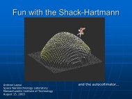
ASS_COLL.eps<br />
Assembly Truss Tests Using Autocollimator<br />
Autocollimator <strong>and</strong> Assembly Truss<br />
Demonstrated 0.5 µm Assembly Accuracy<br />
0.1 µm Repeatability<br />
Microcombs Mounting<br />
a Glass Plate
MLS-2001-05-01.01.eps<br />
X-Rays<br />
Wolter Telescope Reflection Grating Optics<br />
Telescope Optics<br />
Reflection<br />
Gratings<br />
Optical Axis<br />
First-Order Focus<br />
Zero-Order Focus<br />
Rowl<strong>and</strong> Circle<br />
Telescope<br />
Focus
MLS-2001-05-01.02.eps<br />
~2 µm<br />
p max<br />
X-ray Reflection Grating Geometry<br />
100 mm<br />
~2˚<br />
p min<br />
200 mm<br />
pave ~2 µm<br />
Chirp ∆p/p ~5%<br />
Blaze ~2˚<br />
Flatness
MLS-2001-05-02.07.eps<br />
4000 00<br />
000 00<br />
00<br />
000<br />
Super Smooth Reflection Grating Fabrication Results<br />
0<br />
000<br />
2000<br />
3000<br />
4000<br />
Mechanically Ruled <strong>and</strong> Replicated<br />
(XMM Grating - Old Technology)<br />
80<br />
40<br />
nm n<br />
Si (111) planes,<br />
AEF-97-05-23.02<br />
SiO 2<br />
ARC<br />
silicon<br />
(a) Pattern by<br />
Interference Lithography<br />
silicon<br />
(b) Reactive Ion Etch SiO 2,<br />
ARC, <strong>and</strong> Si 3N 4<br />
silicon<br />
(c) RCA Clean<br />
Reflection Grating Fabrication<br />
Process Detail<br />
resist<br />
Si 3 N 4<br />
(111)<br />
Planes<br />
(d) Anisotropically Etch<br />
with KOH<br />
Cr<br />
silicon<br />
silicon<br />
(e) Evaporate Cr &<br />
Wet Etch Si 3N 4<br />
silicon<br />
(f) Reactive Ion Etch Si &<br />
Wet Etch Cr
TAS-ail.eps<br />
Achromatic Interference Lithography<br />
resist-coated<br />
substrate<br />
λ=193 nm<br />
100 nm-period<br />
interference pattern<br />
micrometer<br />
phase grating<br />
(p = 200 nm)<br />
λ=193 nm (ArF excimer) can pattern 100 nm period (10,000 lines/mm)<br />
λ=157 nm (F 2 excimer) can pattern 80 nm period (12,000 lines/mm)
TAS-pmma100<br />
Achromatic Interference Lithography<br />
100 nm<br />
100nm-Period Grating in PMMA<br />
PMMA<br />
ARC<br />
Si
Focus on goals. “Nano” is not a goal.<br />
MIT<br />
SUCCESS FACTORS<br />
• Our lab has a narrow focus: using nanotechnology to improve space instrumentation.<br />
• Other labs successfully focus on applications to spacecraft systems (propulsion, power, attitude, sensors, etc.).<br />
• Nanostructure technologies <strong>and</strong> micro-electro-mechanical systems (MEMS) differ in scale by 1000X, but share<br />
many facilities <strong>and</strong> techniques. We find both technologies important <strong>for</strong> success.<br />
Develop <strong>for</strong> manufacturability.<br />
• Nano-size <strong>and</strong> nano-accuracy are both important.<br />
• Develop fabrication processes <strong>for</strong> tight control <strong>and</strong> manufacturability.<br />
• A large gap exists between lab benchtop demonstrations <strong>and</strong> manufacturing.<br />
• Need best available patterning <strong>and</strong> metrology tools (many are not commercially available).<br />
<br />
Massachusetts Institute <strong>of</strong> Technology
Establish strong connections to university.<br />
• Need best facilities, people <strong>and</strong> ideas.<br />
MIT<br />
SUCCESS FACTORS (continued)<br />
• Young people bring new ideas <strong>and</strong> energy. Pr<strong>of</strong>essors bring experience <strong>and</strong> depth <strong>of</strong> knowledge.<br />
• Integrate academic disciplines into research. Bring together different departments (e.g., mechanical, electrical<br />
& aerospace engineering, physics, chemistry & materials science).<br />
• Students <strong>and</strong> pr<strong>of</strong>essors can find many motivations. <strong>Space</strong> technology brings many new <strong>and</strong> interesting<br />
challenges: low weight <strong>and</strong> power, maximum efficiency <strong>and</strong> sensitivity to detect weak signals, need <strong>for</strong> small<br />
size <strong>and</strong> extreme accuracy, novel structures <strong>and</strong> devices.<br />
Avoid duplicating ef<strong>for</strong>ts.<br />
• Take maximum advantage <strong>of</strong> existing nanotechnology research. Progress is very rapid. Associate primarily<br />
with nanotechnology community, not with space community.<br />
• For example, massive industry investment is driving in<strong>for</strong>mation technology (IT) into the nano regime<br />
(microprocessors, memory, disk media, fiber optics, etc.). Circuit minimum features will reach 30 nm by 2013.<br />
• Much nanotechnology research is in bio/chemical areas. Little <strong>of</strong> this seems to have direct application to space<br />
technology.<br />
• <strong>Nanotechnology</strong> specialization can be important assets <strong>for</strong> “trading” technology with other laboratories.<br />
• Establish connections with industry <strong>and</strong> cultivate common interest.<br />
<br />
Massachusetts Institute <strong>of</strong> Technology
Laboratory Staff<br />
Robert Fleming<br />
James Carter<br />
Edward Murphy<br />
Physics<br />
Nat Butler<br />
Dr. G. S.Pati<br />
Dr. Ralf Heilmann<br />
Glen Monnelly<br />
MIT<br />
ACKNOWLEDGEMENTS<br />
Center <strong>for</strong> <strong>Space</strong> Research<br />
<strong>Space</strong> <strong>Nanotechnology</strong> Laboratory<br />
Electrical Engineering<br />
Carl Chen<br />
Mechanical Engineering<br />
Craig Forest<br />
Chulmin Joo<br />
Paul Konkola<br />
Yanxia Sun<br />
Aero/Astro Engineering<br />
Olivier Mongrard<br />
We thank NASA <strong>for</strong> support <strong>of</strong> this work.<br />
<br />
Massachusetts Institute <strong>of</strong> Technology