

Catalog LV1 T 2009 Chapter 3 EN
Catalog LV1 T 2009 Chapter 3 EN
Catalog LV1 T 2009 Chapter 3 EN

Create successful ePaper yourself
Turn your PDF publications into a flip-book with our unique Google optimized e-Paper software.
3RT, 3RH, 3TB, 3TC, 3TH, 3TK Contactors for Special Applications<br />
■ Overview<br />
AC and DC operation<br />
IEC 60947 (VDE 0660).<br />
The contactors are suitable for use in any climate. The contactors<br />
with screw terminals are finger-safe according to <strong>EN</strong> 50274.<br />
The contactors are available in versions with screw terminals,<br />
6.3 mm plug-in terminals and solder pin connections for soldering<br />
in printed circuit boards.<br />
■ Design<br />
Auxiliary contacts<br />
Contact reliability<br />
To switch voltages ≤ 110 V and currents ≤ 100 mA the 3TH2 contactor<br />
relays should be used as they guarantee a high level of<br />
contact reliability.<br />
These auxiliary contacts are suitable for solid-state circuits with<br />
currents ≥ 1 mA at a voltage of 17 V and higher.<br />
■ Technical specifications<br />
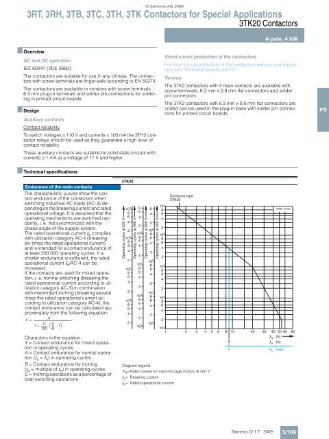
Endurance of the main contacts<br />
The characteristic curves show the contact<br />
endurance of the contactors when<br />
switching inductive AC loads (AC-3) depending<br />
on the breaking current and rated<br />
operational voltage. It is assumed that the<br />
operating mechanisms are switched randomly,<br />
i. e. not synchronized with the<br />
phase angle of the supply system.<br />
The rated operational current Ie complies<br />
with utilization category AC-4 (breaking<br />
six times the rated operational current)<br />
and is intended for a contact endurance of<br />
at least 200 000 operating cycles. If a<br />
shorter endurance is sufficient, the rated<br />
operational current Ie/AC-4 can be<br />
increased.<br />
If the contacts are used for mixed operation,<br />
i. e. normal switching (breaking the<br />
rated operational current according to utilization<br />
category AC-3) in combination<br />
with intermittent inching (breaking several<br />
times the rated operational current according<br />
to utilization category AC-4), the<br />
contact endurance can be calculated approximately<br />
from the following equation:<br />
A<br />
X<br />
1<br />
C<br />
---------<br />
100<br />
A<br />
= ----------------------------------------------------------<br />
+ ⎛--- – 1⎞<br />
⎝B⎠ Characters in the equation:<br />
X = Contact endurance for mixed operation<br />
in operating cycles<br />
A = Contact endurance for normal operation<br />
(I a = I e) in operating cycles<br />
B = Contact endurance for inching<br />
(I a = multiple of I e) in operating cycles<br />
C = Inching operations as a percentage of<br />
total switching operations<br />
3TK20<br />
Operating cycles at 230 V<br />
107 8<br />
6<br />
4<br />
2<br />
106 8<br />
6<br />
4<br />
2<br />
10 5<br />
8<br />
6<br />
4<br />
2<br />
10 4<br />
8<br />
6<br />
4<br />
2<br />
500 V<br />
Operating cycles at<br />
8<br />
6<br />
4<br />
2<br />
10 6<br />
8<br />
6<br />
4<br />
2<br />
10 5<br />
8<br />
6<br />
4<br />
2<br />
10 4<br />
8<br />
6<br />
4<br />
2<br />
10 3<br />
© Siemens AG <strong>2009</strong><br />
690 V<br />
Operating cycles at<br />
6<br />
4<br />
2<br />
106 8<br />
6<br />
4<br />
2<br />
10 5<br />
8<br />
6<br />
4<br />
2<br />
10 4<br />
8<br />
6<br />
4<br />
2<br />
10 3<br />
400 V<br />
Operating cycles at<br />
10 7<br />
8<br />
6<br />
4<br />
2<br />
10<br />
8<br />
6<br />
4<br />
6<br />
Short-circuit protection of the contactors<br />
3TK20 Contactors<br />
Siemens LV 1 T · <strong>2009</strong><br />
4-pole, 4 kW<br />
For short-circuit protection of the contactors without overload relays<br />
see "Technical specifications".<br />
Version<br />
The 3TK2 contactors with 4 main contacts are available with<br />
screw terminals, 6.3 mm x 0.8 mm flat connectors and solder<br />
pin connectors.<br />
The 3TK2 contactors with 6.3 mm x 0.8 mm flat connectors are<br />
coded can be used in the plug-in base with solder pin connections<br />
for printed circuit boards.<br />
2<br />
10 5<br />
8<br />
6<br />
4<br />
2<br />
104 8<br />
6<br />
4<br />
2<br />
Contactor type<br />
3TK20<br />
NSB0_01629<br />
103 1 2 3 4 5 6 8 10 20 30 40 50 60 80<br />
a (A)<br />
9 e (A)<br />
Diagram legend:<br />
PN = Rated power for squirrel-cage motors at 400 V<br />
Ia = Breaking current<br />
Ie = Rated operational current<br />
4 2 N<br />
(kW)<br />
3/109<br />
3


