

Catalog LV1 T 2009 Chapter 3 EN
Catalog LV1 T 2009 Chapter 3 EN
Catalog LV1 T 2009 Chapter 3 EN

Create successful ePaper yourself
Turn your PDF publications into a flip-book with our unique Google optimized e-Paper software.
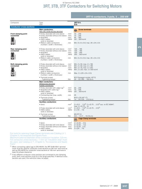
For tools for opening Cage Clamp terminals see <strong>Catalog</strong> LV 1,<br />
<strong>Chapter</strong> 3, Accessories and Spare Parts.<br />
Maximum external diameter of the conductor insulation: 3.6 mm.<br />
For conductor cross-sections ≤ 1 mm² an "insulation stop" must<br />
be used, see <strong>Catalog</strong> LV 1, <strong>Chapter</strong> 3, "Accessories and Spare<br />
Parts".<br />
1) When connecting cable lugs to DIN 46234, the 3RT19 66-4EA1 terminal<br />
cover must be used for conductor cross-sections of 240 mm² and more as<br />
well as DIN 46235 for conductor cross-sections of 185 mm² and more to<br />
keep the phase clearance.<br />
2) If two different conductor cross-sections are connected to one clamping<br />
point, both cross-sections must lie in the range specified. If identical crosssections<br />
are used, this restriction does not apply.<br />
3RT, 3TB, 3TF Contactors for Switching Motors<br />
Contactors Type 3RT10 6.<br />
Size S10<br />
Conductor cross-sections<br />
Front clamping point<br />
connected<br />
<br />
Rear clamping point<br />
connected<br />
<br />
Both clamping points<br />
connected<br />
<br />
Main conductors:<br />
With 3RT19 66-4G box terminal<br />
Screw terminals<br />
Finely stranded with end sleeve mm² 70 ... 240<br />
Finely stranded without end sleeve mm² 70 ... 240<br />
Stranded mm² 95 ... 300<br />
AWG cables,<br />
AWG 3/0 ... 600 kcmil<br />
solid or stranded<br />
Ribbon cable conductors<br />
(number x width x thickness)<br />
mm Min. 6 x 9 x 0.8, max. 20 x 24 x 0.5<br />
Finely stranded with end sleeve mm² 120 ... 185<br />
Finely stranded without end sleeve mm² 120 ... 185<br />
Stranded mm² 120 ... 240<br />
AWG cables,<br />
AWG 250 ... 500 kcmil<br />
solid or stranded<br />
Ribbon cable conductors<br />
(number x width x thickness)<br />
mm Min. 6 x 9 x 0.8, max. 20 x 24 x 0.5<br />
Finely stranded with end sleeve mm² Min. 2 x 50, max. 2 x 185<br />
Finely stranded without end sleeve mm² Min. 2 x 50, max. 2 x 185<br />
Stranded mm² Min. 2 x 70, max. 2 x 240<br />
AWG cables,<br />
AWG Min. 2 x 2/0, max. 2 x 500 kcmil<br />
solid or stranded<br />
© Siemens AG <strong>2009</strong><br />
Ribbon cable conductors<br />
(number x width x thickness)<br />
mm Max. 2 x (20 x 24 x 0.5)<br />
Terminal screws M12 (hexagon socket, A/F 5)<br />
- Tightening torque<br />
Main conductors:<br />
Without box terminal/<br />
busbar connection<br />
Nm 20 ... 22 (180 ... 195 lb.in)<br />
Finely stranded with cable lug 1)<br />
Stranded with cable lug<br />
mm² 50 ... 240<br />
1)<br />
mm² 70 ... 240<br />
AWG cables,<br />
solid or stranded<br />
AWG 2/0 ... 500 kcmil<br />
Connecting bar (max. width) mm 25<br />
Terminal screws M10 x 30 (A/F 17)<br />
- Tightening torque Nm 14 ... 24 (124 ... 210 lb.in)<br />
Auxiliary conductors:<br />
Solid mm 2<br />
3RT10 contactors, 3-pole, 3 ... 250 kW<br />
2 x (0.5 ... 1.5) 2) ; 2 x (0.75 ... 2.5) 2) acc. to IEC 60947;<br />
max. 2 x (0.75 ... 4)<br />
Finely stranded with end sleeve mm2 2 x (0.5 ... 1.5) 2) ; 2 x (0.75 ... 2.5) 2)<br />
AWG cables,<br />
solid or stranded<br />
AWG 2 x (18 ... 14)<br />
Terminal screws M3 (PZ 2)<br />
- Tightening torque Nm 0.8 ... 1.2 (7 ... 10.3 lb.in)<br />
Auxiliary conductors: Cage Clamp terminals<br />
Solid mm 2<br />
Finely stranded with end sleeve mm<br />
2 x (0.25 ... 2.5)<br />
2<br />
Finely stranded without end sleeve mm<br />
2 x (0.25 ... 1.5)<br />
2 2 x (0.25 ...2.5)<br />
AWG cables,<br />
solid or stranded<br />
AWG 2 x (24 ... 14)<br />
Siemens LV 1 T · <strong>2009</strong><br />
3/47<br />
3


