

Catalog LV1 T 2009 Chapter 3 EN
Catalog LV1 T 2009 Chapter 3 EN
Catalog LV1 T 2009 Chapter 3 EN

You also want an ePaper? Increase the reach of your titles
YUMPU automatically turns print PDFs into web optimized ePapers that Google loves.
■ Technical specifications<br />
SIRIUS controls are climate-proof and are suitable and tested for<br />
use worldwide.<br />
If the devices are used in ambient conditions which deviate from<br />
common industrial conditions (<strong>EN</strong> 60721-3-3 "Stationary Use,<br />
1) Snap-on auxiliary switch blocks for size S00 and laterally mountable auxiliary<br />
switch blocks for S0 to S12: 6 A.<br />
© Siemens AG <strong>2009</strong><br />
3RT, 3TB, 3TF Contactors for Switching Motors<br />
3RT10 contactors, 3-pole, 3 ... 250 kW<br />
Weather-Protected"), the manufacturer must be consulted about<br />
possible restrictions with regard to the reliability and endurance<br />
of the device and possible protective measures.<br />
Contactors Type 3RT1<br />
Size S00 ... S12<br />
Rated data of the auxiliary contacts<br />
Acc. to IEC 60947-5-1/<strong>EN</strong> 60947-5-1 (VDE 0660 Part 200)<br />
The data apply to integrated auxiliary contacts and contacts in the auxiliary<br />
switch blocks for contactor sizes S00 to S12 1)<br />
Rated insulation voltage Ui (degree of pollution 3)<br />
For 3RH19 21-. laterally mountable auxiliary switch blocks<br />
V<br />
V<br />
690<br />
Max. 500<br />
Continuous thermal current Ith =<br />
Rated operational current Ie /AC-12<br />
AC load<br />
Rated operational current Ie /AC-15/AC-14<br />
A 10<br />
For rated operational voltage Ue 24 V<br />
110 V<br />
A<br />
A<br />
6<br />
6<br />
125 V A 6<br />
220 V A 6<br />
230 V A 6<br />
380 V A 3<br />
400 V A 3<br />
500 V<br />
660 V<br />
A 2<br />
2) 690 V<br />
A 1<br />
2)<br />
DC load<br />
Rated operational current Ie /DC-12<br />
A 1<br />
For rated operational voltage Ue 24 V<br />
60 V<br />
A<br />
A<br />
10<br />
6<br />
110 V A 3<br />
125 V A 2<br />
220 V A 1<br />
440 V<br />
600 V<br />
A 0.3<br />
2)<br />
Rated operational current Ie/DC-13 A 0.15<br />
For rated operational voltage Ue 24 V A 10 1)<br />
60 V A 2<br />
110 V A 1<br />
125 V A 0.9<br />
220 V A 0.3<br />
440 V<br />
600 V<br />
A 0.14<br />
2)<br />
A 0.1<br />
Contact reliability at 17 V, 1 mA<br />
Frequency of contact faults < 10<br />
acc. to <strong>EN</strong> 60947-5-4<br />
-8 i. e. < 1 fault per 100 million<br />
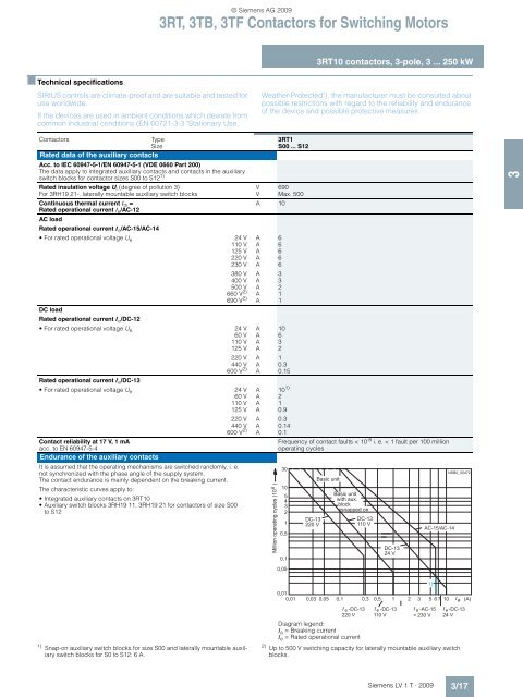
Endurance of the auxiliary contacts<br />
operating cycles<br />
It is assumed that the operating mechanisms are switched randomly, i. e.<br />
not synchronized with the phase angle of the supply system.<br />
30<br />
NSB0_00472<br />
The contact endurance is mainly dependent on the breaking current.<br />
Basic unit<br />
The characteristic curves apply to:<br />
Integrated auxiliary contacts on 3RT10<br />
Auxiliary switch blocks 3RH19 11, 3RH19 21 for contactors of size S00<br />
to S12<br />
10<br />
5<br />
4<br />
3<br />
2<br />
Basic unit<br />
with aux.<br />
block<br />
snapped on<br />
1<br />
0,5<br />
DC-13<br />
220 V<br />
DC-13<br />
110 V<br />
AC-15/AC-14<br />
Million operating cycles (10 6 )<br />
0,1<br />
0,05<br />
DC-13<br />
24 V<br />
0,01<br />
0,01 0,03 0,05 0,1 0,3 0,5 1 2 3 5 6 7 10 Ia<br />
(A)<br />
I e -DC-13 I e -DC-13 I e -AC-15 I e -DC-13<br />
220 V 110 V<br />
< 230 V 24 V<br />
Diagram legend:<br />
Ia = Breaking current<br />
Ie = Rated operational current<br />
2)<br />
Up to 500 V switching capacity for laterally mountable auxiliary switch<br />
blocks.<br />
1)<br />
Siemens LV 1 T · <strong>2009</strong><br />
3/17<br />
3


