

Catalog LV1 T 2009 Chapter 3 EN
Catalog LV1 T 2009 Chapter 3 EN
Catalog LV1 T 2009 Chapter 3 EN

Create successful ePaper yourself
Turn your PDF publications into a flip-book with our unique Google optimized e-Paper software.
■ Overview<br />
AC and DC operation<br />
IEC 60947 (VDE 0660).<br />
The terminal designations comply with <strong>EN</strong> 50011.<br />
3TH2 contactor relays<br />
The 3TH2 contactor relays are suitable for use in any climate.<br />
The contactor relays with screw terminals are finger-safe according<br />
to <strong>EN</strong> 50274.<br />
3TH27 latched contactor relays<br />
The contactor coil and the coil of the release solenoid are both<br />
designed for uninterrupted duty.<br />
RC elements, varistors diodes or diode assemblies can be fitted<br />
to both coils from the front for damping opening surges in the<br />
coil.<br />
The contactor relay can also be switched on and released<br />
manually.<br />
■ Design<br />
3TH2 contactor relays<br />
Version<br />
The 3TH20 contactors with 4 auxiliary contacts are available with<br />
SIGUT screw terminals, 6.3 mm x 0.8 mm flat connectors and<br />
solder pin connections.<br />
The contactors with 6.3 mm x 0.8 mm flat connectors can be<br />
used in the plug-in base with solder pin connections for printed<br />
circuit boards. The contactor relays are coded and the plug-in<br />
base is codable in order to ensure non-interchangeability.<br />
The 3TH22 contactor relays with 8 integrated contacts are available<br />
with screw terminals. The terminal designations are according<br />
to <strong>EN</strong> 50011.<br />
Contact reliability<br />
High contact stability at low voltages and currents, suitable for<br />
solid-state circuits with currents ≥ 1 mA at a voltage of 17 V and<br />
higher.<br />
Auxiliary switch blocks<br />
The contactor relays with 4 contacts with screw terminals relays<br />
can be expanded by up to four contacts by the addition of snapon<br />
auxiliary switch blocks.<br />
A cover (with unit labeling plate) must be removed from the front<br />
of the contactor for this purpose. The auxiliary switch block is<br />
then easy to mount. The auxiliary switch blocks can be removed<br />
again by unlocking them with a laterally arranged slide.<br />
The contactor relays with screw terminals with 4 contacts according<br />
to <strong>EN</strong> 50011, with the identification number 40E, can be extended<br />
with 80E, 71E, 62E, 53E or 44E auxiliary switch blocks to<br />
obtain contactor relays with 8 contacts according to <strong>EN</strong> 50011.<br />
The identification numbers 80E, 71E, 62E, 53E or 44E on the<br />
coded auxiliary switch blocks apply to the complete contactors<br />
(see graphic on the right). These auxiliary switch blocks cannot<br />
be combined with contactor relays with identification number 31E<br />
and 33E.<br />
All contactor relays with screw terminals with 4 contacts according<br />
to <strong>EN</strong> 50011, identification number 40E, 31E or 22E, can be<br />
extended with auxiliary switch blocks with identification number<br />
40, 31, 22, 20, 11 or 02 to obtain contactor relays with 6 or 8 contacts<br />
according to <strong>EN</strong> 50005. The identification numbers on the<br />
auxiliary switch blocks apply only to the attached auxiliary<br />
switch blocks (see the graphic on the right).<br />
© Siemens AG <strong>2009</strong><br />
3RH, 3TH Contactor Relays<br />
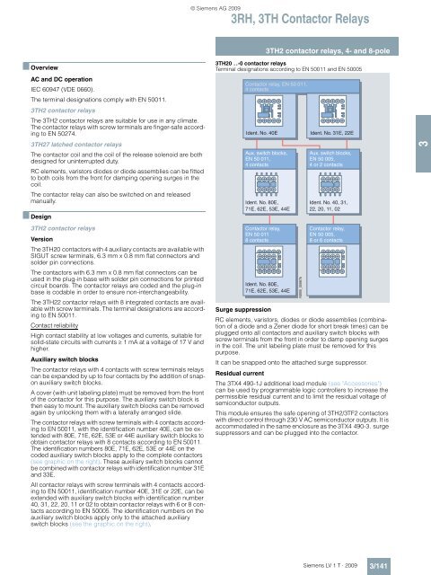
3TH2 contactor relays, 4- and 8-pole<br />
3TH20 . .-0 contactor relays<br />
Terminal designations according to <strong>EN</strong> 50011 and <strong>EN</strong> 50005<br />
Contactor relay, <strong>EN</strong> 50 011,<br />
4 contacts<br />
Ident. No. 40E<br />
Aux. switch blocks,<br />
<strong>EN</strong> 50 011,<br />
4 contacts<br />
Ident. No. 80E,<br />
71E, 62E, 53E, 44E<br />
Contactor relay,<br />
<strong>EN</strong> 50 011<br />
8 contacts<br />
Ident. No. 80E,<br />
71E, 62E, 53E, 44E<br />
NSB0_00067b<br />
Ident. No. 31E, 22E<br />
Aux. switch blocks,<br />
<strong>EN</strong> 50 005,<br />
4 or 2 contacts<br />
Ident. No. 40, 31,<br />
22, 20, 11, 02<br />
Contactor<br />
Hilfsschütze<br />
relay,<br />
<strong>EN</strong><br />
DIN<br />
50<br />
<strong>EN</strong>50<br />
005,<br />
005,<br />
8<br />
8<br />
or<br />
oder<br />
6 contacts<br />
6 Kontakte<br />
Surge suppression<br />
RC elements, varistors, diodes or diode assemblies (combination<br />
of a diode and a Zener diode for short break times) can be<br />
plugged onto all contactors and auxiliary switch blocks with<br />
screw terminals from the front in order to damp opening surges<br />
in the coil. The unit labeling plate must be removed for this<br />
purpose.<br />
It can be snapped onto the attached surge suppressor.<br />
Residual current<br />
The 3TX4 490-1J additional load module (see "Accessories")<br />
can be used by programmable logic controllers to increase the<br />
permissible residual current and to limit the residual voltage of<br />
semiconductor outputs.<br />
This module ensures the safe opening of 3TH2/3TF2 contactors<br />
with direct control through 230 V AC semiconductor outputs. It is<br />
accommodated in the same enclosure as the 3TX4 490-3. surge<br />
suppressors and can be plugged into the contactor.<br />
Siemens LV 1 T · <strong>2009</strong><br />
3/141<br />
3


