

Catalog LV1 T 2009 Chapter 3 EN
Catalog LV1 T 2009 Chapter 3 EN
Catalog LV1 T 2009 Chapter 3 EN

Create successful ePaper yourself
Turn your PDF publications into a flip-book with our unique Google optimized e-Paper software.
3<br />
Controls — Contactors and Contactor Assemblies<br />
Project planning aids<br />
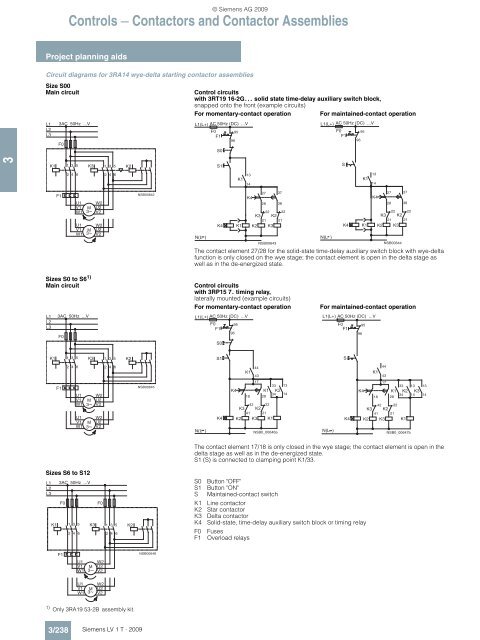
Circuit diagrams for 3RA14 wye-delta starting contactor assemblies<br />
Size S00<br />
Main circuit Control circuits<br />
with 3RT19 16-2G. . . solid state time-delay auxiliary switch block,<br />
snapped onto the front (example circuits)<br />
For momentary-contact operation For maintained-contact operation<br />
L1<br />
L2<br />
L3<br />
F0<br />
K1 1 3 5<br />
2 4 6<br />
K3<br />
F1<br />
1) Only 3RA19 53-2B assembly kit.<br />
3/238<br />
3AC 50Hz ...V<br />
U1<br />
V1<br />
W1<br />
U1<br />
V1<br />
W1<br />
M<br />
3~<br />
M<br />
3~<br />
Siemens LV 1 T · <strong>2009</strong><br />
The contact element 27/28 for the solid-state time-delay auxiliary switch block with wye-delta<br />
function is only closed on the wye stage; the contact element is open in the delta stage as<br />
well as in the de-energized state.<br />
Sizes S0 to S6 1)<br />
Main circuit Control circuits<br />
with 3RP15 7. timing relay,<br />
laterally mounted (example circuits)<br />
For momentary-contact operation For maintained-contact operation<br />
L1<br />
L2<br />
L3<br />
F0<br />
K1 1 3 5<br />
2 4 6<br />
K3<br />
F1<br />
U1<br />
V1<br />
W1<br />
M<br />
3~<br />
Sizes S6 to S12<br />
L1<br />
L2<br />
L3<br />
3AC 50Hz ...V<br />
U1<br />
V1<br />
W1<br />
M<br />
3~<br />
3AC 50Hz ...V<br />
F0<br />
K1 1 3 5<br />
2 4 6<br />
K3<br />
F1<br />
U1<br />
V1<br />
W1<br />
U1<br />
V1<br />
W1<br />
M<br />
3~<br />
M<br />
3~<br />
W2<br />
U2<br />
V2<br />
W2<br />
U2<br />
V2<br />
W2<br />
U2<br />
V2<br />
W2<br />
U2<br />
V2<br />
F0<br />
W2<br />
U2<br />
V2<br />
W2<br />
U2<br />
V2<br />
1 3 5<br />
2 4 6<br />
1 3 5<br />
2 4 6<br />
1 3 5<br />
2 4 6<br />
K2<br />
K2<br />
K2<br />
NSB00642<br />
NSB00645<br />
NSB00648<br />
L1(L+) AC 50Hz (DC) ...V<br />
F0 95<br />
F1<br />
96<br />
N(L )<br />
<br />
© Siemens AG <strong>2009</strong><br />
S0<br />
S1<br />
K4<br />
13<br />
K1<br />
14<br />
) + # 0 , + 8<br />
.<br />
' #<br />
.<br />
' $<br />
5<br />
5<br />
"<br />
"<br />
K4<br />
27<br />
28 38<br />
K3<br />
22<br />
K2<br />
22<br />
21 21<br />
K1 K2 K3<br />
<br />
" "<br />
" !<br />
"<br />
! <br />
"<br />
!<br />
NSB00643<br />
%<br />
! !<br />
<br />
& &<br />
! "<br />
5 * $ " $ =<br />
<br />
37<br />
L1(L+) AC 50Hz (DC) ...V<br />
F0<br />
95<br />
F1<br />
96<br />
The contact element 17/18 is only closed in the wye stage; the contact element is open in the<br />
delta stage as well as in the de-energized state.<br />
S1 (S) is connected to clamping point K1/33.<br />
N(L )<br />
S0 Button "OFF"<br />
S1 Button "ON"<br />
S Maintained-contact switch<br />
K1 Line contactor<br />
K2 Star contactor<br />
K3 Delta contactor<br />
K4 Solid-state, time-delay auxiliary switch block or timing relay<br />
F0 Fuses<br />
F1 Overload relays<br />
!<br />
"<br />
S<br />
K4<br />
K1<br />
13<br />
14<br />
K4<br />
L1(L+) AC 50Hz (DC) ...V<br />
F0 95<br />
F1<br />
96<br />
N(L )<br />
S<br />
K4<br />
27<br />
28 38<br />
K3<br />
22<br />
K2<br />
21 21<br />
K1 K2 K3<br />
22<br />
K4<br />
K1<br />
NSB00644<br />
44<br />
43<br />
17<br />
33<br />
37<br />
K1 K2 K3<br />
34 14 14<br />
18 28<br />
K3<br />
42<br />
K2<br />
22<br />
41 21<br />
K2 K3 K1<br />
NSB0_00647b<br />
13<br />
13


