GEL 210 K - ertech.ch
GEL 210 K - ertech.ch
GEL 210 K - ertech.ch

You also want an ePaper? Increase the reach of your titles
YUMPU automatically turns print PDFs into web optimized ePapers that Google loves.
D-02A-<strong>210</strong>_Y004/5/7<br />
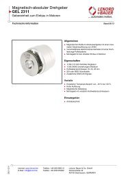
Testing device<br />
<strong>GEL</strong> <strong>210</strong> Y004/Y005/Y007<br />
for encoders with sinusoidal output 1 V SS<br />
Operating information Version 2010-10<br />
1<br />
Messberei<strong>ch</strong>staster<br />
Amplitude Spur A<br />
Amplitude Spur B<br />
Offset Spur A<br />
Offset Spur B<br />
Phase Spur A zu B<br />
Peak Referenzspur<br />
Offset Referenzspur<br />
Nullage<br />
Internet: www.lenord.de<br />
E-Mail: info@lenord.de<br />
+5 Volt ext.<br />
2<br />
3<br />
Phone: +49 208 9963–0<br />
Fax: +49 208 676292<br />
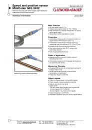
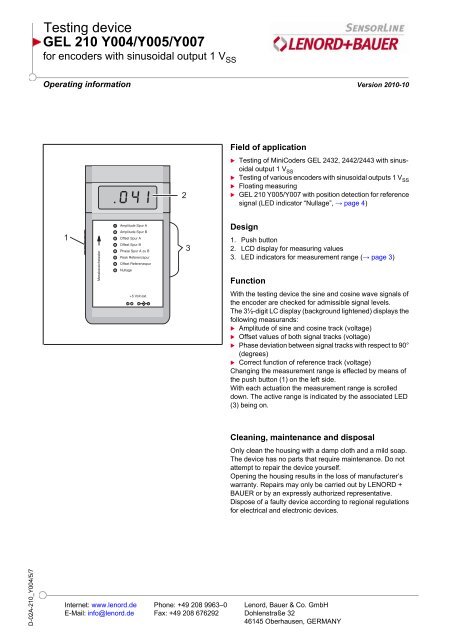
Field of application<br />
Testing of MiniCoders <strong>GEL</strong> 2432, 2442/2443 with sinusoidal<br />
output 1 VSS Testing of various encoders with sinusoidal outputs 1 VSS Floating measuring<br />
<strong>GEL</strong> <strong>210</strong> Y005/Y007 with position detection for reference<br />
signal (LED indicator “Nullage”, → page 4)<br />
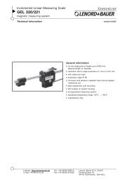
Design<br />
1. Push button<br />
2. LCD display for measuring values<br />
3. LED indicators for measurement range (→ page 3)<br />
Function<br />
With the testing device the sine and cosine wave signals of<br />
the encoder are <strong>ch</strong>ecked for admissible signal levels.<br />
The 3½-digit LC display (background lightened) displays the<br />
following measurands:<br />
Amplitude of sine and cosine track (voltage)<br />
Offset values of both signal tracks (voltage)<br />
Phase deviation between signal tracks with respect to 90°<br />
(degrees)<br />
Correct function of reference track (voltage)<br />
Changing the measurement range is effected by means of<br />
the push button (1) on the left side.<br />
With ea<strong>ch</strong> actuation the measurement range is scrolled<br />
down. The active range is indicated by the associated LED<br />
(3) being on.<br />
Cleaning, maintenance and disposal<br />
Only clean the housing with a damp cloth and a mild soap.<br />
The device has no parts that require maintenance. Do not<br />
attempt to repair the device yourself.<br />
Opening the housing results in the loss of manufacturer’s<br />
warranty. Repairs may only be carried out by LENORD +<br />
BAUER or by an expressly authorized representative.<br />
Dispose of a faulty device according to regional regulations<br />
for electrical and electronic devices.<br />
Lenord, Bauer & Co. GmbH<br />
Dohlenstraße 32<br />
46145 Oberhausen, GERMANY
Te<strong>ch</strong>nical Data and Connections<br />
Te<strong>ch</strong>nical data<br />
General Data<br />
Operating voltage 5 V DC ± 5%<br />
Mains adapter 5 V, stabilised<br />
Current consumption (without encoder) < 100 mA<br />
Frequency range 0.1 to 4 kHz<br />
Operating temperature +10°C to +40 °C<br />
Weight (without mains adapter) 200 g<br />
Dimensions (WxLxD)<br />
Measuring accuracy<br />
84 mm x 157 mm x 30 mm<br />
Measuring error for amplitude (peak to peak) tracks A, B ± 2% (0.1 to 2 kHz)<br />
Measuring error for reference signal (peak) ± 10% (0.1 to 2 kHz)<br />
Offset tracks A, B and reference signal ± 0.2%<br />
Phase deviation from 90° ± 0.2°<br />
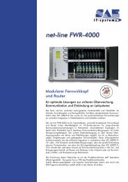
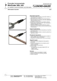
Connection<br />
Messberei<strong>ch</strong>staster<br />
Amplitude Spur A<br />
Amplitude Spur B<br />
Offset Spur A<br />
Offset Spur B<br />
Phase Spur A zu B<br />
Peak Referenzspur<br />
Offset Referenzspur<br />
Nullage<br />
+5 Volt ext.<br />
alternative:<br />
Connect the encoder to a 10-pole terminal strip with screw contacts and unique orientation. Plug-in the terminal strip<br />
on the top side of the testing device.<br />
Plug in the included mains adapter on the bottom of the test device.<br />
Alternative: Connect the 5 Volts power supply to a 2-pole terminal strip with screw contacts and plug it on the bottom<br />
side of the device.<br />
2 Lenord+Bauer D-02A-<strong>210</strong>_Y004/5/7(2010-10)<br />
n.c.<br />
GND<br />
UN- UN+ n.c.<br />
UB- UB+ UA- UA+ +5 V<br />
GND<br />
+5 V<br />
blue<br />
yellow<br />
grey<br />
green<br />
black<br />
pink<br />
brown<br />
white<br />
red
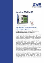
Overview of measurement ranges<br />
Measurements<br />
Measurement range Indicator Measuring values and tolerance range 1)<br />
Air gap measurement<br />
Amplitude (peak to peak)<br />
U A+ , U A-<br />
U B+ , U B-<br />
Offset measurement U A+ , U A-<br />
U B+ , U B-<br />
Phase measurement U A+ , U B+<br />
Amplitude track A 1 V SS ± 0.2 V SS<br />
Amplitude track B 1 V SS ± 0.2 V SS<br />
Offset track A 0 ± 0.02 V DC<br />
Offset track B 0 ± 0.02 V DC<br />
Phase track A to track B<br />
(deviation from 90°)<br />
1) The measuring values and tolerance ranges depend on the control used. Please observe the manufacturer’s specifications.<br />
D-02A-<strong>210</strong>_Y004/5/7(2010-10) Lenord+Bauer 3<br />
< 1°
Measurements<br />
Measurement range Indicator Measuring values and tolerance range 1)<br />
Reference signal U A+ , U B+<br />
U A+ , U B+<br />
Amplitude (Peak) > 0.2 V<br />
Offset -0.1 to -0.4 V DC<br />
1) The measuring values and tolerance ranges depend on the control used. Please observe the manufacturer’s specifications.<br />
Zero position detection of <strong>GEL</strong> <strong>210</strong> Y005 and<br />
Y007<br />
Zero position detection is always active and<br />
cannot be swit<strong>ch</strong>ed off by means of the push<br />
button.<br />
With rotating target wheel, the correct orientation of the reference<br />
signal (N) is signalled by the 'Nullage' LED being on<br />
continuously.<br />
Nullage<br />
Once the reference track is detected the LED is on for about<br />
10 seconds.<br />
Subject to te<strong>ch</strong>nical modifications and typographical errors.<br />
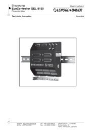
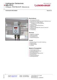
Orientation of the reference signal<br />
The correct orientation of the reference signal in relation to<br />
the track signal UA = (UA+ - UA- ) depends on the testing device:<br />
<strong>GEL</strong> <strong>210</strong>Y005 135° ± 45°<br />
<strong>GEL</strong> <strong>210</strong>Y007 135° ± 90°<br />
Ideally, the reference signal UN is centered between the<br />
peaks of the track signals UA and UB .<br />
UN<br />
U<br />
U<br />
4 Lenord+Bauer D-02A-<strong>210</strong>_Y004/5/7(2010-10)<br />
B<br />
Ideal position of the reference signal U N<br />
A<br />
2.5 V