Chapter 1 - ERTICO.com
Chapter 1 - ERTICO.com
Chapter 1 - ERTICO.com

You also want an ePaper? Increase the reach of your titles
YUMPU automatically turns print PDFs into web optimized ePapers that Google loves.
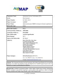
Global System for<br />
Telematics<br />
Release DEL_RSQ_3_1<br />
Architecture and<br />
Interface Specifications<br />
Author(s) Alessandro Murro - WP3 Manager (Mizar Automazione SpA)<br />
Date Contractual: 6/27/2005 Actual: 3/23/2006<br />
SP Manager Rasmus D. Lindholm<br />
<strong>ERTICO</strong>-ITS EUROPE<br />
Tel: +32 2 400 07 30<br />
E-Mail: r.lindholm@mail.ertico.<strong>com</strong><br />
IP Manager Peter Van der Perre<br />
<strong>ERTICO</strong>-ITS EUROPE<br />
Tel: +32 2 400 07 36<br />
E-Mail: p.vanderperre@mail.ertico.<strong>com</strong><br />
Abstract This is the first deliverable in WP3 - Architecture and Interface<br />
Specifications for the RSQ sub-project in GST.<br />
Keyword list RSQ sub-project, Architecture and Interface Specifications.<br />
Nature of<br />
deliverable<br />
Deliverable<br />
Number<br />
Version<br />
Number<br />
Report<br />
DEL_RSQ_3_1<br />
2.0<br />
Dissemination PP<br />
Project financially supported by<br />
Project number FP6-2002-IST-1-507033<br />
European Union<br />
DG INFSO
Version<br />
number<br />
DEL_RSQ_3_1 Architecture and Interface Specifications<br />
Control Sheet<br />
Version history<br />
Date Main author Summary of<br />
changes<br />
0.1 15.11.2004 Alessandro Murro First Draft - System<br />
Overview<br />
0.2 13.12.2004 Alessandro Murro Update and Review<br />
0.3 25.1.2005 Alessandro Murro Update<br />
0.4 15.2.2005 Alessandro Murro Review on the basis<br />
of GF remarks<br />
0.5 14.3.2005 Alessandro Murro Review and Update<br />
0.6 22.3.2005 Alessandro Murro Review on the basis<br />
of GF remarks<br />
0.7 18.5.2005 Alessandro Murro Review and Update<br />
on the basis of<br />
Synch Meeting<br />
0.8 29.6.2005 Alessandro Murro Review and Update<br />
with partner’s<br />
contribution<br />
0.9 15.8.2005 Alessandro Murro Review and Update<br />
with partner’s<br />
contribution<br />
1.0 29.09.2005 Alessandro Murro Final Review and<br />
Release Version<br />
2.0 21.03.2006 Amaury Denoo Review and 2 nd<br />
Approval<br />
Release Version<br />
Name Date<br />
Prepared Alessandro Murro 21.03.2006<br />
Reviewed Rasmus Lindholm 22.03.2006<br />
Authorised Rasmus Lindholm 22.03.2006<br />
Circulation<br />
Recipient Date of submission<br />
Project partners 23.03.2006<br />
European Commission 23.03.2006<br />
3/23/2006 II Version 2.0
DEL_RSQ_3_1 Architecture and Interface Specifications<br />
Table of Contents<br />
PART 1 - INTRODUCTION AND ENTERPRISE VIEW................................. 18<br />
CHAPTER 1 - INTRODUCTION..................................................................... 19<br />
1.1 Intended Audience .........................................................................................19<br />
1.2 Organisation ...................................................................................................19<br />
1.3 Conventions ....................................................................................................20<br />
1.4 Typographic Conventions .............................................................................20<br />
1.5 Objectives........................................................................................................20<br />
CHAPTER 2 - EXECUTIVE SUMMARY ........................................................ 22<br />
CHAPTER 3 - METHODOLOGY FOR THE DELIVERABLE........................ 23<br />
3.1 Introduction....................................................................................................23<br />
3.2 Architecture Documents................................................................................23<br />
3.2.1 Content of the IP-level Deliverables........................................................24<br />
3.2.2 Content of the SP-level Deliverables.......................................................24<br />
3.3 The Viewpoint Approach of RM-ODP [1]...................................................24<br />
3.4 The Unified Modelling Language (UML) [2] ..............................................24<br />
3.5 Structure of this Document...........................................................................25<br />
3.6 Consistency with IP-level Deliverables ........................................................26<br />
CHAPTER 4 - SYSTEM OVERVIEW............................................................. 27<br />
4.1 Introduction....................................................................................................27<br />
4.2 PSAP1, PSAP2 and Telco Roles ...................................................................29<br />
4.3 Use Cases and Collaborations for RESCUE ...............................................30<br />
4.4 Architecture Elements ...................................................................................37<br />
4.5 Short Description per Element .....................................................................39<br />
PART 2 - LOGICAL VIEW ............................................................................. 59<br />
3/23/2006 3 Version 2.0
DEL_RSQ_3_1 Architecture and Interface Specifications<br />
CHAPTER 5 - LOGICAL VIEW PART STRUCTURE ................................... 60<br />
5.1 Introduction....................................................................................................60<br />
5.2 Organisation of the Logical View Part <strong>Chapter</strong>s........................................60<br />
5.3 RESCUE Collaborations overview...............................................................62<br />
5.3.1 UC RSQ 001 – Triggers Automatic Calls Collaborations .......................63<br />
5.3.2 UC RSQ 002 – PSAP1 Collaborations ...................................................64<br />
5.3.3 UC RSQ 003 – PSAP2 Collaborations ....................................................64<br />
5.3.4 UC RSQ 004 – Data to Vehicle Collaborations.......................................65<br />
5.3.5 UC RSQ 005 – Route Guidance Collaborations......................................66<br />
5.3.6 UC RSQ 006 – Blue Wave Collaborations..............................................67<br />
5.3.7 UC RSQ 007 – Virtual Cones Collaborations .........................................68<br />
5.3.8 UC RSQ 008 – Value Added Data Collaborations..................................69<br />
5.4 Relationship between Work Items and Liaisons.........................................70<br />
5.5 Logical View Work Focusing........................................................................71<br />
5.6 Reading Specifications...................................................................................82<br />
CHAPTER 6 - VEHICLE ECALL.................................................................... 84<br />
6.1 UC RSQ 001 - PV - ECALL Activation (Manual/Automatic)...................84<br />
6.1.1 Introduction..............................................................................................84<br />
6.1.2 Use Case Diagram....................................................................................84<br />
6.1.3 Interfaces..................................................................................................85<br />
6.1.4 API Specification.....................................................................................85<br />
6.1.5 Interactions...............................................................................................86<br />
6.1.6 Lifecycles.................................................................................................88<br />
6.2 UC RSQ 001 – PV - ECALL Manual Cancelling........................................89<br />
6.2.1 Introduction..............................................................................................89<br />
6.2.2 Use Case Diagram....................................................................................89<br />
6.2.3 Interfaces..................................................................................................90<br />
6.2.4 API Specification.....................................................................................91<br />
6.2.5 Interactions...............................................................................................92<br />
6.2.6 Lifecycles.................................................................................................93<br />
6.3 UC RSQ 001 - PV - Emergency Data Handling..........................................94<br />
6.3.1 Introduction..............................................................................................94<br />
6.3.2 Use Case Diagram....................................................................................95<br />
6.3.3 Interfaces..................................................................................................96<br />
6.3.4 API Specification.....................................................................................96<br />
6.3.5 Interactions...............................................................................................97<br />
6.3.6 Lifecycles.................................................................................................98<br />
6.4 UC RSQ 001 - PV - Emergency Data Message Sending.............................99<br />
6.4.1 Introduction..............................................................................................99<br />
3/23/2006 4 Version 2.0
DEL_RSQ_3_1 Architecture and Interface Specifications<br />
6.4.2 Use Case Diagram..................................................................................100<br />
6.4.3 Interfaces................................................................................................101<br />
6.4.4 Protocol Stack and Specification ...........................................................102<br />
6.4.5 Message Structure..................................................................................109<br />
6.4.6 API Specification...................................................................................116<br />
6.4.7 Interactions.............................................................................................117<br />
6.4.8 Lifecycles...............................................................................................118<br />
CHAPTER 7 - PSAP ECALL ....................................................................... 119<br />
7.1 UC RSQ 002 – UC RSQ 003 – PSAP – Emergency Data Visualisation..119<br />
7.1.1 Introduction............................................................................................119<br />
7.1.2 Use Case Diagram..................................................................................119<br />
7.1.3 Interfaces................................................................................................120<br />
7.1.4 API Specification...................................................................................121<br />
7.1.5 Interactions.............................................................................................122<br />
7.1.6 Lifecycles...............................................................................................123<br />
7.2 UC RSQ 002 – PSAP - Emergency Data Handling...................................124<br />
7.2.1 Introduction............................................................................................124<br />
7.2.2 Use Case Diagram..................................................................................124<br />
7.2.3 Interfaces................................................................................................125<br />
7.2.4 API Specification...................................................................................125<br />
7.2.5 Interactions.............................................................................................126<br />
7.2.6 Lifecycles...............................................................................................128<br />
7.3 UC RSQ 003 – PSAP2 - Emergency Data Retrieving from PSAP1 ........129<br />
7.3.1 Introduction............................................................................................129<br />
7.3.2 Use Case Diagram..................................................................................129<br />
7.3.3 Interfaces................................................................................................130<br />
7.3.4 Protocol Stack and Specification ...........................................................130<br />
7.3.5 Message Structure..................................................................................131<br />
7.3.6 API Specification...................................................................................134<br />
7.3.7 Interactions.............................................................................................135<br />
7.3.8 Lifecycles...............................................................................................136<br />
7.4 UC RSQ 002 – PSAP1 – EOS......................................................................137<br />
7.4.1 Introduction............................................................................................137<br />
7.4.2 Use Case Diagram..................................................................................137<br />
7.4.3 Interfaces................................................................................................138<br />
7.4.4 Protocol Stack and Specification ...........................................................138<br />
7.4.5 Message Structure..................................................................................140<br />
7.4.6 API Specification...................................................................................140<br />
7.4.7 Interactions.............................................................................................141<br />
7.4.8 Lifecycles...............................................................................................142<br />
CHAPTER 8 - PSAP RESCUE MANAGEMENT......................................... 143<br />
8.1 UC RSQ 003 - Transmission of Data..........................................................143<br />
3/23/2006 5 Version 2.0
DEL_RSQ_3_1 Architecture and Interface Specifications<br />
8.1.1 Introduction............................................................................................143<br />
8.1.2 Use Case Diagram..................................................................................143<br />
8.1.3 Interfaces................................................................................................144<br />
8.1.4 Protocol Stack and Specification ...........................................................144<br />
8.1.5 Message Structure..................................................................................145<br />
8.1.6 API Specification...................................................................................147<br />
8.1.7 Interactions.............................................................................................149<br />
8.1.8 Lifecycles...............................................................................................150<br />
8.2 UC RSQ 003 – ESV - Emergency Handling Closure................................151<br />
8.2.1 Introduction............................................................................................151<br />
8.2.2 Use Case Diagram..................................................................................151<br />
8.2.3 Interfaces................................................................................................152<br />
8.2.4 Protocol Stack and Specification ...........................................................152<br />
8.2.5 Message Structure..................................................................................153<br />
8.2.6 API Specification...................................................................................155<br />
8.2.7 Interactions.............................................................................................156<br />
8.2.8 Lifecycles...............................................................................................158<br />
CHAPTER 9 - PSAP TO VEHICLE COMMUNICATION ............................. 159<br />
9.1 UC RSQ 004 - ESV - Emergency Data Receipt from PSAP2 ..................159<br />
9.1.1 Introduction............................................................................................159<br />
9.1.2 Use Case Diagram..................................................................................159<br />
9.1.3 Interfaces................................................................................................160<br />
9.1.4 Protocol Stack and Specification ...........................................................160<br />
9.1.5 Message Structure..................................................................................161<br />
9.1.6 API Specification...................................................................................164<br />
9.1.7 Interactions.............................................................................................167<br />
9.1.8 Lifecycles...............................................................................................169<br />
CHAPTER 10 - ESV RESCUE MANAGEMENT.......................................... 170<br />
10.1 UC RSQ 004 - ESV - Emergency Data Visualisation ...............................170<br />
10.1.1 Introduction............................................................................................170<br />
10.1.2 Use Case Diagram..................................................................................170<br />
10.1.3 Interfaces................................................................................................171<br />
10.1.4 API Specification...................................................................................171<br />
10.1.5 Interactions.............................................................................................173<br />
10.1.6 Lifecycles...............................................................................................175<br />
10.2 UC RSQ 004 - ESV - Accept Deployment..................................................176<br />
10.2.1 Introduction............................................................................................176<br />
10.2.2 Use Case Diagram..................................................................................176<br />
10.2.3 Interfaces................................................................................................177<br />
10.2.4 Protocol Stack and Specification ...........................................................177<br />
10.2.5 Message Structure..................................................................................178<br />
10.2.6 API Specification...................................................................................179<br />
10.2.7 Interactions.............................................................................................180<br />
3/23/2006 6 Version 2.0
DEL_RSQ_3_1 Architecture and Interface Specifications<br />
10.2.8 Lifecycles...............................................................................................182<br />
CHAPTER 11 - ESV DRIVER SUPPORT.................................................... 183<br />
11.1 UC RSQ 005 – ESV - Calculate Route Options ........................................183<br />
11.1.1 Introduction............................................................................................183<br />
11.1.2 Use Case Diagram..................................................................................183<br />
11.1.3 Interfaces................................................................................................184<br />
11.1.4 Protocol Stack and Specification ...........................................................185<br />
11.1.5 Message Structure..................................................................................186<br />
11.1.6 API Specification...................................................................................198<br />
11.1.7 Interactions.............................................................................................201<br />
11.1.8 Lifecycles...............................................................................................202<br />
11.2 UC RSQ 005 – ESV - Display Route Options............................................204<br />
11.2.1 Introduction............................................................................................204<br />
11.2.2 Use Case Diagram..................................................................................204<br />
11.2.3 Interfaces................................................................................................205<br />
11.2.4 API Specification...................................................................................205<br />
11.2.5 Interactions.............................................................................................206<br />
11.2.6 Lifecycles...............................................................................................208<br />
11.3 UC RSQ 005 – ESV - Target Information Reception...............................210<br />
11.3.1 Introduction............................................................................................210<br />
11.3.2 Use Case Diagram..................................................................................210<br />
11.3.3 Interfaces................................................................................................210<br />
11.3.4 Protocol Stack and Specification ...........................................................212<br />
11.3.5 Message Structure..................................................................................213<br />
11.3.6 API Specification...................................................................................216<br />
11.3.7 Interactions.............................................................................................218<br />
11.3.8 Lifecycles...............................................................................................220<br />
CHAPTER 12 - VEHICLE TO VEHICLE COMMUNICATION ..................... 221<br />
12.1 UC RSQ 006 & 007– ESV – Activate Warning Messages........................221<br />
12.1.1 Introduction............................................................................................221<br />
12.1.2 Use Case Diagram..................................................................................221<br />
12.1.3 Interfaces................................................................................................222<br />
12.1.4 API Specification...................................................................................222<br />
12.1.5 Interactions.............................................................................................223<br />
12.1.6 Lifecycles...............................................................................................224<br />
12.2 UC RSQ 006 & 007– ESV – Reset Transmission......................................224<br />
12.2.1 Introduction............................................................................................224<br />
12.2.2 Use Case Diagram..................................................................................225<br />
12.2.3 Interfaces................................................................................................226<br />
12.2.4 API Specification...................................................................................226<br />
12.2.5 Interactions.............................................................................................228<br />
12.2.6 Lifecycles...............................................................................................229<br />
3/23/2006 7 Version 2.0
DEL_RSQ_3_1 Architecture and Interface Specifications<br />
12.3 UC RSQ 006 & 007– ESV – Send Warning Message ...............................230<br />
12.3.1 Introduction............................................................................................230<br />
12.3.2 Use Case Diagram..................................................................................230<br />
12.3.3 Interfaces................................................................................................231<br />
12.3.4 Protocol Stack and Specification ...........................................................231<br />
12.3.5 Message Structure..................................................................................232<br />
12.3.6 API Specification...................................................................................233<br />
12.3.7 Interactions.............................................................................................235<br />
12.3.8 Lifecycles...............................................................................................237<br />
12.4 UC RSQ 006 & 007– PV – Interpret Warning Message ..........................238<br />
12.4.1 Introduction............................................................................................238<br />
12.4.2 Use Case Diagram..................................................................................238<br />
12.4.3 Interfaces................................................................................................239<br />
12.4.4 API Specification...................................................................................239<br />
12.4.5 Interactions.............................................................................................241<br />
12.4.6 Lifecycles...............................................................................................243<br />
12.5 UC RSQ 006 & 007– PV – Receive Warning Message .............................244<br />
12.5.1 Introduction............................................................................................244<br />
12.5.2 Use Case Diagram..................................................................................244<br />
12.5.3 Interfaces................................................................................................245<br />
12.5.4 API Specification...................................................................................245<br />
12.5.5 Interactions.............................................................................................246<br />
12.5.6 Lifecycles...............................................................................................247<br />
CHAPTER 13 - PUBLIC VEHICLE DRIVER SUPPORT............................. 248<br />
13.1 UC RSQ 006 - PV - Reset Warning Message ............................................248<br />
13.1.1 Introduction............................................................................................248<br />
13.1.2 Use Case Diagram..................................................................................248<br />
13.1.3 Interfaces................................................................................................249<br />
13.1.4 API Specification...................................................................................249<br />
13.1.5 Interactions.............................................................................................250<br />
13.1.6 Lifecycles...............................................................................................252<br />
CHAPTER 14 - VEHICLE TO CENTRE COMMUNICATION...................... 253<br />
14.1 UC RSQ 008 – Transmission of Data.........................................................253<br />
14.1.1 Introduction............................................................................................253<br />
14.1.2 Use Case Diagram..................................................................................253<br />
14.1.3 Interfaces................................................................................................254<br />
14.1.4 Protocol Stack and Specification ...........................................................254<br />
14.1.5 Message Structure..................................................................................255<br />
14.1.6 API Specification...................................................................................258<br />
14.1.7 Interactions.............................................................................................261<br />
14.1.8 Lifecycles...............................................................................................266<br />
14.2 UC RSQ 008 – Processing of Data..............................................................267<br />
3/23/2006 8 Version 2.0
DEL_RSQ_3_1 Architecture and Interface Specifications<br />
14.2.1 Introduction............................................................................................267<br />
14.2.2 Use Case Diagram..................................................................................267<br />
14.2.3 Interfaces................................................................................................268<br />
14.2.4 API Specification...................................................................................269<br />
14.2.5 Interactions.............................................................................................270<br />
14.2.6 Lifecycles...............................................................................................271<br />
14.3 UC RSQ 008 – Collation of Data ................................................................271<br />
14.3.1 Introduction............................................................................................271<br />
14.3.2 Use Case Diagram..................................................................................272<br />
14.3.3 Interfaces................................................................................................273<br />
14.3.4 API Specification...................................................................................273<br />
14.3.5 Interactions.............................................................................................275<br />
14.3.6 Lifecycles...............................................................................................276<br />
14.4 UC RSQ 008 – ESV – Receive Data ...........................................................276<br />
14.4.1 Introduction............................................................................................276<br />
14.4.2 Use Case Diagram..................................................................................277<br />
14.4.3 Interfaces................................................................................................278<br />
14.4.4 Protocol Stack and Specification ...........................................................278<br />
14.4.5 Message Structure..................................................................................279<br />
14.4.6 API Specification...................................................................................282<br />
14.4.7 Interactions.............................................................................................284<br />
14.4.8 Lifecycles...............................................................................................287<br />
14.5 UC RSQ 008 – ESV – Data Transferred....................................................287<br />
14.5.1 Introduction............................................................................................287<br />
14.5.2 Use Case Diagram..................................................................................288<br />
14.5.3 Interfaces................................................................................................289<br />
14.5.4 API Specification...................................................................................289<br />
14.5.5 Interactions.............................................................................................291<br />
14.5.6 Lifecycles...............................................................................................292<br />
CHAPTER 15 - SECURITY .......................................................................... 293<br />
15.1 Check Security Authorisation.....................................................................293<br />
15.1.1 Introduction............................................................................................293<br />
CHAPTER 16 - SYSTEM MANAGEMENT .................................................. 294<br />
16.1 Introduction..................................................................................................294<br />
16.2 UC RSQ 001 - PV - Acknowledge of Data Sent.........................................294<br />
16.2.1 Introduction............................................................................................294<br />
16.2.2 Use Case Diagram..................................................................................295<br />
16.2.3 Interfaces................................................................................................296<br />
16.2.4 Protocol Stack and Specification ...........................................................296<br />
16.2.5 Message Structure.................................... Error! Bookmark not defined.<br />
16.2.6 Message Structure..................................................................................298<br />
16.2.7 API Specification...................................................................................298<br />
3/23/2006 9 Version 2.0
DEL_RSQ_3_1 Architecture and Interface Specifications<br />
16.2.8 Interactions.............................................................................................299<br />
16.2.9 Lifecycles...............................................................................................300<br />
16.3 System Management Liaisons.....................................................................300<br />
PART 3 - IMPLEMENTATION VIEW AND CONCLUSIONS ...................... 302<br />
CHAPTER 17 - IMPLEMENTATION VIEW PART STRUCTURE ............... 303<br />
17.1 Introduction..................................................................................................303<br />
17.2 Organisation of the Implementation View Part <strong>Chapter</strong>s .......................303<br />
CHAPTER 18 - REFERENCE IMPLEMENTATION .................................... 305<br />
18.1 Vehicle ECALL ............................................................................................305<br />
18.1.1 Components ...........................................................................................305<br />
18.1.2 Nodes .....................................................................................................306<br />
18.2 PSAP ECALL...............................................................................................308<br />
18.2.1 Components ...........................................................................................308<br />
18.2.2 Nodes .....................................................................................................310<br />
18.3 PSAP Rescue Management .........................................................................311<br />
18.3.1 Components ...........................................................................................311<br />
18.3.2 Nodes .....................................................................................................313<br />
18.4 PSAP to Vehicle Communication...............................................................314<br />
18.4.1 Components ...........................................................................................314<br />
18.4.2 Nodes .....................................................................................................315<br />
18.5 ESV Rescue Management ...........................................................................316<br />
18.5.1 Components ...........................................................................................316<br />
18.5.2 Nodes .....................................................................................................317<br />
18.6 ESV Driver Support ....................................................................................319<br />
18.6.1 Components ...........................................................................................319<br />
18.6.2 Nodes .....................................................................................................322<br />
18.7 Vehicle to Vehicle Communication ............................................................324<br />
18.7.1 Components ...........................................................................................324<br />
18.7.2 Nodes .....................................................................................................326<br />
18.8 Public Vehicle Driver Support....................................................................328<br />
18.8.1 Components ...........................................................................................328<br />
18.8.2 Nodes .....................................................................................................329<br />
18.9 Vehicle to Centre Communication .............................................................331<br />
18.9.1 Components ...........................................................................................331<br />
18.9.2 Nodes .....................................................................................................332<br />
3/23/2006 10 Version 2.0
DEL_RSQ_3_1 Architecture and Interface Specifications<br />
18.10 Security .....................................................................................................333<br />
18.11 System Management................................................................................333<br />
CHAPTER 19 - ARCHITECTURAL ISSUES AND DECISIONS ................. 334<br />
19.1 Vehicle sensors to be triggered ...................................................................334<br />
19.1.1 Objectives ..............................................................................................334<br />
19.1.2 Triggers ..................................................................................................334<br />
19.1.3 Thresholds..............................................................................................336<br />
19.1.4 Source Document...................................................................................336<br />
19.2 eCall service Messages.................................................................................336<br />
19.2.1 Problem identification............................................................................336<br />
19.2.2 Decision .................................................................................................337<br />
19.2.3 Source Document...................................................................................338<br />
19.3 How to transmit MSD from Vehicle to PSAP1 – USSD Protocol............339<br />
19.3.1 Description.............................................................................................339<br />
19.3.2 Definition ...............................................................................................339<br />
19.3.3 Reference Normative .............................................................................340<br />
19.3.4 Deployment:...........................................................................................340<br />
19.3.5 Source Document...................................................................................341<br />
19.4 Guidelines for Emergency Data Visualisation at PSAP Operator ..........341<br />
19.4.1 Problem identification............................................................................341<br />
19.4.2 Decision .................................................................................................341<br />
19.4.3 Arguments..............................................................................................342<br />
19.4.4 Source Document...................................................................................342<br />
19.5 Human Factors Guidelines for Route Navigation System .......................342<br />
19.5.1 Problem identification............................................................................342<br />
19.5.2 List of Alternative Solutions..................................................................343<br />
19.5.3 Decision .................................................................................................343<br />
19.6 HMI considerations for the use of the Blue Wave / Virtual Cones<br />
application in an Emergency Services Vehicle......................................................344<br />
19.6.1 Problem identification............................................................................344<br />
19.6.2 List of Alternative Solutions..................................................................344<br />
19.6.3 Decision .................................................................................................345<br />
19.7 HMI considerations for the presentation of Blue Wave / Virtual Cones<br />
information in a Public Vehicle ..............................................................................345<br />
19.7.1 Problem identification............................................................................345<br />
19.7.2 List of Alternative Solutions..................................................................345<br />
19.7.3 Decision .................................................................................................345<br />
19.8 Value Added Data Application Suite .........................................................346<br />
19.8.1 Problem identification............................................................................346<br />
19.8.2 Possible Scenarios..................................................................................347<br />
3/23/2006 11 Version 2.0
DEL_RSQ_3_1 Architecture and Interface Specifications<br />
19.8.3 Decisions................................................................................................349<br />
19.9 Value Added Data Streaming .....................................................................350<br />
19.9.1 Problem identification............................................................................350<br />
19.9.2 List of Alternative Solutions..................................................................353<br />
19.9.3 Decision .................................................................................................353<br />
19.9.4 Arguments..............................................................................................354<br />
19.9.5 Source Document...................................................................................360<br />
19.10 Test and Certification of the eCall protocol at the level of new<br />
implementations .......................................................................................................360<br />
19.10.1 Problem identification........................................................................360<br />
19.10.2 List of Alternative Solutions..............................................................361<br />
19.10.3 Decision .............................................................................................363<br />
19.10.4 Consequences of the decision ............................................................363<br />
19.10.5 Source Document...............................................................................363<br />
19.11 eCall timing issues....................................................................................363<br />
19.11.1 Definitions..........................................................................................363<br />
19.11.2 Legal Issues........................................................................................365<br />
19.11.3 Legal Liabilities .................................................................................366<br />
19.11.4 Network Security ...............................................................................367<br />
19.11.5 Source Document...............................................................................367<br />
19.12 HMI Design Re<strong>com</strong>mendations for eCall system .................................367<br />
19.12.1 Introduction........................................................................................367<br />
19.12.2 Problem identification........................................................................367<br />
19.12.3 Ease of Use ........................................................................................368<br />
19.12.4 Feedback from the system .................................................................369<br />
19.12.5 Driver distraction prevention .............................................................369<br />
19.12.6 Reducing the number of accidental/false calls...................................369<br />
19.12.7 Source Document...............................................................................370<br />
CHAPTER 20 - CONCLUSIONS AND NEXT STEPS ................................. 371<br />
20.1 Conclusions...................................................................................................371<br />
20.2 GST RESCUE Specifications Assessment .................................................372<br />
20.3 Compliance Matrix ......................................................................................373<br />
PART 4 - APPENDIX SECTION .................................................................. 407<br />
APPENDIX A - TERMS AND ABBREVIATIONS ........................................ 408<br />
APPENDIX B - REFERENCES.................................................................... 410<br />
APPENDIX C - CODE SECTION ................................................................. 412<br />
3/23/2006 12 Version 2.0
DEL_RSQ_3_1 Architecture and Interface Specifications<br />
Table of Figures<br />
Figure 1 - Sub-project Components.............................................................................22<br />
Figure 2 - RESCUE concept overview ........................................................................28<br />
Figure 3 – Collaborations of UC RSQ 001 – Triggers Automatic Call......................30<br />
Figure 4 – Collaborations of UC RSQ 002 – PSAP1 .................................................31<br />
Figure 5 – Collaborations of UC RSQ 003 – PSAP2 .................................................32<br />
Figure 6 – Collaborations of UC RSQ 004 – Data to Vehicle....................................33<br />
Figure 7 – Collaborations of UC RSQ 005 – Route Guidance...................................34<br />
Figure 8 – Collaborations of UC RSQ 006 – Blue Wave...........................................35<br />
Figure 9 – Collaborations of UC RSQ 007 – Virtual Cones.......................................36<br />
Figure 10 – Collaborations of UC RSQ 008 – Value Added Data .............................37<br />
Figure 11 - System Overview and Reference Points for the RSQ Sub-Project ...........38<br />
Figure 12 - Collaborations for the RSQ Sub-Project ...................................................39<br />
Figure 13 – GST and OSI Protocol Layers <strong>com</strong>parison ..............................................61<br />
Figure 14 – Collaboration – PV - ECALL Activation (entities involved)...................84<br />
Figure 15 - PV - ECALL Activation (Manual/Automatic)..........................................84<br />
Figure 16 - Class Diagram for ECALL Activation (Manual/Automatic)....................85<br />
Figure 17 - Sequence Diagram showing start of an ECALL Activation<br />
(Manual/Automatic).............................................................................................86<br />
Figure 18 - State Chart Diagram for ECALL Activation (Manual/Automatic)...........88<br />
Figure 19 - Activity Diagram for ECALL Activation (Manual/Automatic) ...............88<br />
Figure 20 – Collaboration PV ECALL Manual Cancelling.........................................89<br />
Figure 21 - PV ECALL Manual Cancelling ................................................................90<br />
Figure 22 - Class Diagram for PV ECALL Manual Cancelling..................................90<br />
Figure 23 - Sequence Diagram showing PV ECALL Manual Cancelling ..................92<br />
Figure 24 - State Chart Diagram showing PV ECALL Manual Cancelling................93<br />
Figure 25 - Activity Diagram showing PV ECALL Manual Cancelling.....................94<br />
Figure 26 – Collaboration PV - Emergency Data Handling .......................................95<br />
Figure 27 - PV – Emergency Data Handling ...............................................................95<br />
Figure 28 - Class Diagram for PV - Emergency Data Handling .................................96<br />
Figure 29 - Sequence Diagram showing PV - Emergency Data Handling..................97<br />
Figure 30 - State Chart Diagram for PV - Emergency Data Handling ........................98<br />
Figure 31 - Activity Diagram for PV - Emergency Data Handling.............................99<br />
Figure 32 – Collaboration PV - Emergency Data Message Sending........................100<br />
Figure 33 – Use Case PV - Emergency Data Message Sending...............................100<br />
Figure 34 - Class Diagram for PV - Emergency Data Message Sending .................101<br />
Figure 35 – Protocol Stack - PV - Emergency Data Message Sending ....................102<br />
Figure 36 – eCall transaction .....................................................................................106<br />
Figure 37 - Sequence Diagram showing PV - Emergency Data Message Sending..117<br />
Figure 38 - State Chart Diagram showing PV - Emergency Data Message Sending118<br />
Figure 39 – Collaboration – PSAP Emergency Data Visualisation...........................119<br />
Figure 40 – Use Case – PSAP Emergency Data Visualisation..................................120<br />
Figure 41 - Class Diagram PSAP Emergency Data Visualisation.............................120<br />
Figure 42 - Sequence Diagram showing PSAP Emergency Data Visualisation .......122<br />
Figure 43 - Activity Diagram showing PSAP Emergency Data Visualisation..........123<br />
Figure 44 – Collaboration – PSAP - Emergency Data Handling...............................124<br />
3/23/2006 13 Version 2.0
DEL_RSQ_3_1 Architecture and Interface Specifications<br />
Figure 45 – Use Case – PSAP - Emergency Data Handling......................................124<br />
Figure 46 - Class Diagram PSAP - Emergency Data Handling.................................125<br />
Figure 47 - Sequence Diagram showing PSAP - Emergency Data Handling ...........126<br />
Figure 48 - Activity Diagram showing PSAP - Emergency Data Handling..............128<br />
Figure 49 – Collaboration – PSAP2 - Emergency Data Retrieving from PSAP1 .....129<br />
Figure 50 – Use Case – PSAP2 - Emergency Data Retrieving from PSAP1 ............130<br />
Figure 51 - Class Diagram PSAP2 - Emergency Data Retrieving from PSAP1 .......130<br />
Figure 52 – Protocol Stack - PSAP2 - Emergency Data Retrieving from PSAP1 ....131<br />
Figure 53 - Sequence Diagram showing PSAP2 - Emergency Data Retrieving from<br />
PSAP1................................................................................................................135<br />
Figure 54 - Activity Diagram showing PSAP2 - Emergency Data Retrieving from<br />
PSAP1................................................................................................................136<br />
Figure 55 – Collaboration – PSAP1 - EOS................................................................137<br />
Figure 56 – Use Case – PSAP1 – EOS......................................................................137<br />
Figure 57 - Class Diagram for PSAP1 – EOS ...........................................................138<br />
Figure 58 – Protocol Stack – PSAP1 - EOS ..............................................................139<br />
Figure 59 - Sequence Diagram showing PSAP1 – EOS............................................141<br />
Figure 60 - State Chart Diagram showing PSAP1 – EOS .........................................142<br />
Figure 61 –Transmission of Data (entities involved) ................................................143<br />
Figure 62 - Transmission of Data ..............................................................................143<br />
Figure 63 - Class Diagram for Transmission of Data................................................144<br />
Figure 64 – Protocol Stack – Transmission of Data ..................................................145<br />
Figure 65 - Sequence Diagram showing Transmission of Data ................................149<br />
Figure 66 - State Chart Diagram showing Transmission of Data..............................150<br />
Figure 67 – Collaboration – ESV - Emergency Handling Closure............................151<br />
Figure 68 – Use Case – ESV - Emergency Handling Closure...................................151<br />
Figure 69 - Class Diagram ESV - Emergency Handling Closure..............................152<br />
Figure 70 – Protocol Stack - ESV - Emergency Handling Closure...........................153<br />
Figure 71 – Message Structure ..................................................................................154<br />
Figure 72 - Sequence Diagram showing ESV - Emergency Handling Closure ........156<br />
Figure 73 - Activity Diagram showing ESV - Emergency Handling Closure...........158<br />
Figure 74 – Collaboration – ESV – Emergency Data Receipt from PSAP2 .............159<br />
Figure 75 – Use Case - ESV – Emergency Data Receipt from PSAP2.....................159<br />
Figure 76 - Class Diagram for ESV – Emergency Data Receipt from PSAP2..........160<br />
Figure 77 – Protocol Stack – ESV – Emergency Data Receipt from PSAP2............161<br />
Figure 78 – Message Structure ..................................................................................162<br />
Figure 79 - Sequence Diagram showing ESV – Emergency Data Receipt from PSAP2<br />
............................................................................................................................167<br />
Figure 80 - State Chart Diagram showing ESV – Emergency Data Receipt from<br />
PSAP2................................................................................................................169<br />
Figure 81 – Collaboration – ESV – Emergency Data Visualisation..........................170<br />
Figure 82 – Use Case – ESV – Emergency Data Visualisation.................................170<br />
Figure 83 - Class Diagram for ESV – Emergency Data Visualisation ......................171<br />
Figure 84 - Sequence Diagram showing ESV – Emergency Data Visualisation ......173<br />
Figure 85 - State Chart Diagram showing ESV – Emergency Data Visualisation....175<br />
Figure 86 – Collaboration – ESV – Accept Deployment ..........................................176<br />
Figure 87 - ESV – Accept Deployment .....................................................................176<br />
Figure 88 - Class Diagram for ESV – Accept Deployment.......................................177<br />
Figure 89 – Protocol Stack - ESV – Accept Deployment..........................................178<br />
3/23/2006 14 Version 2.0
DEL_RSQ_3_1 Architecture and Interface Specifications<br />
Figure 90 - Sequence Diagram showing ESV – Accept Deployment .......................180<br />
Figure 91 - State Chart Diagram showing ESV – Accept Deployment.....................182<br />
Figure 92 – Collaboration ESV Calculate Route Options .........................................183<br />
Figure 93 - ESV Calculate Route Options.................................................................183<br />
Figure 94 - Class Diagram for ESV Calculate Route Options...................................184<br />
Figure 95 – Protocol Stack – ESV – Calculate Route Options..................................185<br />
Figure 96: Map and route visualisation sample .........................................................198<br />
Figure 97 - Sequence Diagram showing ESV Calculate Route Options ...................201<br />
Figure 98 - State Chart Diagram showing ESV Calculate Route Options ................203<br />
Figure 99 – Collaboration Display Route Options ....................................................204<br />
Figure 100 – ESV Display Route Options.................................................................204<br />
Figure 101 - Class Diagram for ESV Display Route Options ...................................205<br />
Figure 102 - Sequence Diagram showing ESV Display Route Options....................206<br />
Figure 103 - State Chart Diagram showing ESV Display Route Options .................208<br />
Figure 104 - Activity Diagram showing ESV Display Route Options......................209<br />
Figure 105 – Collaboration Target Information Reception .......................................210<br />
Figure 106 – ESV Target Information Reception......................................................210<br />
Figure 107 - Class Diagram for ESV Target Information Reception ........................211<br />
Figure 108 – Protocol Stack - ESV Target Information Reception ...........................213<br />
Figure 109 - Sequence Diagram showing ESV Target Information Reception.........218<br />
Figure 110 - State Chart Diagram showing ESV Target Information Reception ......220<br />
Figure 111 – Collaboration - ESV Activate Warning Messages ...............................221<br />
Figure 112 – Use Case - ESV Activate Warning Messages ......................................221<br />
Figure 113 - Class Diagram for ESV Activate Warning Messages...........................222<br />
Figure 114 - Sequence Diagram showing ESV Activate Warning Messages ...........223<br />
Figure 115 - Activity Diagram showing ESV Activate Warning Messages .............224<br />
Figure 116 – Collaboration - ESV Reset Transmission.............................................225<br />
Figure 117 – Use Case – ESV Reset Transmission ...................................................225<br />
Figure 118 - Class Diagram for ESV Reset Transmission ........................................226<br />
Figure 119 - Sequence Diagram showing ESV Reset Transmission.........................228<br />
Figure 120 - Activity Diagram showing ESV Reset Transmission ...........................229<br />
Figure 121 – Collaboration - ESV Send Warning Message ......................................230<br />
Figure 122 – Use Case – ESV Send Warning Message.............................................230<br />
Figure 123 - Class Diagram for ESV Send Warning Message..................................231<br />
Figure 124 – Protocol Stack - ESV Send Warning Message.....................................232<br />
Figure 125 - Sequence Diagram showing ESV Send Warning Message ..................235<br />
Figure 126 - Activity Diagram showing ESV Send Warning Message.....................237<br />
Figure 127 – Collaboration – PV Interpret Warning Message ..................................238<br />
Figure 128 – Use Case – PV Interpret Warning Message .........................................238<br />
Figure 129 - Class Diagram for PV Interpret Warning Message...............................239<br />
Figure 130 - Sequence Diagram showing PV Interpret Warning Message...............241<br />
Figure 131 - Activity Diagram showing PV Interpret Warning Message .................243<br />
Figure 132 – Collaboration - PV Receive Warning Message....................................244<br />
Figure 133 – Use Case – PV Receive Warning Message ..........................................244<br />
Figure 134 - Class Diagram for PV Receive Warning Message ...............................245<br />
Figure 135 - Sequence Diagram showing PV Receive Warning Message................246<br />
Figure 136 - Activity Diagram showing PV Receive Warning Message ..................247<br />
Figure 137 – Collaboration – PV - Reset Warning Message.....................................248<br />
Figure 138 – Use Case – PV - Reset Warning Message............................................248<br />
3/23/2006 15 Version 2.0
DEL_RSQ_3_1 Architecture and Interface Specifications<br />
Figure 139 - Class Diagram for PV - Reset Warning Message .................................249<br />
Figure 140 - Sequence Diagram showing PV - Reset Warning Message..................250<br />
Figure 141 - State Chart Diagram showing PV - Reset Warning Message...............252<br />
Figure 142 - Transmission of Data (entities involved) ..............................................253<br />
Figure 143 - Transmission of Data ............................................................................253<br />
Figure 144 - Class Diagram for Transmission of Data..............................................254<br />
Figure 145 – Protocol Stack – Transmission of Data ................................................255<br />
Figure 146 - Sequence Diagram showing Transmission of Data – PUSH Case .......261<br />
Figure 147 – Sequence Diagram showing Transmission of Data – PUSH Case to<br />
PSAP2................................................................................................................262<br />
Figure 148 - Sequence Diagram showing Transmission of Data – PULL Case........262<br />
Figure 149 - Sequence Diagram showing Transmission of Live VAD .....................265<br />
Figure 150 - Activity Diagram showing Transmission of Data.................................267<br />
Figure 151 – Processing of Data (entities involved)..................................................267<br />
Figure 152 - Processing of Data.................................................................................268<br />
Figure 153 - Class Diagram for Processing of Data ..................................................268<br />
Figure 154 - Sequence Diagram showing Processing of Data...................................270<br />
Figure 155 - State Chart Diagram showing Processing of Data ................................271<br />
Figure 156 – Collation of Data (entities involved) ....................................................272<br />
Figure 157 - Collation of Data...................................................................................272<br />
Figure 158 - Class Diagram for Collation of Data.....................................................273<br />
Figure 159 - Sequence Diagram showing Collation of Data .....................................275<br />
Figure 160 - State Chart Diagram showing Collation of Data...................................276<br />
Figure 161 – ESV – Receive Data (entities involved)...............................................277<br />
Figure 162 - ESV – Receive Data..............................................................................277<br />
Figure 163 - Class Diagram for ESV – Receive Data ...............................................278<br />
Figure 164 – Protocol Stack – ESV – Receive Data..................................................279<br />
Figure 165 - Sequence Diagram showing ESV – Receive Data – PUSH Case.........284<br />
Figure 166 - Sequence Diagram showing ESV – Receive Data – PULL Case .........285<br />
Figure 167 - State Chart Diagram showing ESV – Receive Data .............................287<br />
Figure 168 – ESV – Data Transferred (entities involved) .........................................288<br />
Figure 169 - ESV – Data Transferred ........................................................................288<br />
Figure 170 - Class Diagram for ESV – Data Transferred..........................................289<br />
Figure 171 - Sequence Diagram showing ESV – Data Transferred ..........................291<br />
Figure 172 - State Chart Diagram showing ESV – Data Transferred........................292<br />
Figure 173 – UC RSQ 001 – PV – Acknowledge of Data Sent (entities involved) ..295<br />
Figure 174 - UC RSQ 001 – PV – Acknowledge of Data Sent .................................295<br />
Figure 175 - Class Diagram for UC RSQ 001 – PV – Acknowledge of Data Sent...296<br />
Figure 176 – Protocol Stack - PV – Acknowledge of Data Sent ...............................297<br />
Figure 177 - Sequence Diagram showing UC RSQ 001 – PV – Acknowledge of Data<br />
Sent ....................................................................................................................299<br />
Figure 178 - State Chart Diagram showing UC RSQ 001 – PV – Acknowledge of<br />
Data Sent............................................................................................................300<br />
Figure 179 - Component Diagram for Vehicle ECALL work Item...........................305<br />
Figure 180 - Deployment Diagram for Vehicle ECALL work item..........................307<br />
Figure 181 - Component Diagram for PSAP ECALL work item..............................308<br />
Figure 182 - Deployment Diagram for PSAP ECALL work item.............................310<br />
Figure 183 - Component Diagram for PSAP Rescue Management work item .........311<br />
Figure 184 - Deployment Diagram for PSAP Rescue Management work item........313<br />
3/23/2006 16 Version 2.0
DEL_RSQ_3_1 Architecture and Interface Specifications<br />
Figure 185 - Component Diagram for PSAP to Vehicle Communication work item314<br />
Figure 186 - Deployment Diagram for PSAP to Vehicle Communication work item<br />
............................................................................................................................315<br />
Figure 187 - Component Diagram for ESV Rescue Management work item ...........316<br />
Figure 188 - Deployment Diagram for ESV Rescue Management work item..........317<br />
Figure 189 - Component Diagram for ESV Driver Support work item ....................319<br />
Figure 190 - Deployment Diagram for ESV Driver Support work item ...................322<br />
Figure 191 - Component Diagram for Vehicle to Vehicle Communication work item<br />
............................................................................................................................324<br />
Figure 192 - Deployment Diagram for Vehicle to Vehicle Communication work item<br />
............................................................................................................................326<br />
Figure 193 - Component Diagram for Public Vehicle Driver Support work item ....328<br />
Figure 194 - Deployment Diagram for Public Vehicle Driver Support work item ...329<br />
Figure 195 - Component Diagram for Vehicle to Centre Communication work item<br />
............................................................................................................................331<br />
Figure 196 - Deployment Diagram for Vehicle to Centre Communication work item<br />
............................................................................................................................332<br />
Figure 197 - Representation of sequence events........................................................337<br />
Figure 198 – eCall Service Messages ........................................................................338<br />
Figure 199 – USSD service architecture (extract from CEPT ECC)........................340<br />
Figure 200 – PSAP Operator Work Station...............................................................342<br />
Figure 201 – Value Added Data Streaming - PUSH CASE ......................................347<br />
Figure 202 – Value Added Data Streaming - PULL CASE ......................................348<br />
Figure 203 – Value Added Data Streaming - PUSH CASE to PSAP2 .....................349<br />
Figure 204 – ND-CS Protocol Stack [19]..................................................................349<br />
Figure 205 – Video Streaming System ......................................................................352<br />
Figure 206 – RTSP Operation....................................................................................355<br />
Figure 207 – RTSP Protocol States ...........................................................................360<br />
Figure 208 – Example of a test MSD message processing by PSAP1 IS..................362<br />
Figure 209 – Time scheme of eCall process [9] ........................................................365<br />
3/23/2006 17 Version 2.0
DEL_RSQ_3_1 Architecture and Interface Specifications<br />
PART 1 - INTRODUCTION AND<br />
ENTERPRISE VIEW<br />
3/23/2006 18 Version 2.0
<strong>Chapter</strong> 1 - INTRODUCTION<br />
1.1 Intended Audience<br />
DEL_RSQ_3_1 Architecture and Interface Specifications<br />
This document is primarily written for the members of the SP. Some versions of the<br />
document will be circulated to IPWP3MT, CT and CAG for IP-level co-ordination<br />
purposes. The final version will be sent to GA.<br />
1.2 Organisation<br />
This document consists of the following sections:<br />
• Introduction and Enterprise View<br />
o Introduction – this chapter.<br />
o Executive Summary – provides a high level overview of information<br />
provided by this document. Read this chapter if you only need a basic<br />
understanding of the architecture and design options documented by this<br />
deliverable.<br />
o Methodology for the Deliverable – in order to achieve an optimal result, the<br />
definition of the GST RESCUE architecture is supported by a light but<br />
efficient methodology. The information provided by this chapter will help<br />
you in understanding the different steps taken whilst developing this<br />
deliverable and rationale behind some of the document result.<br />
o System Overview – this chapter connects the architecture and design<br />
exercise ac<strong>com</strong>plished by WP3 to the results promoted by the GST<br />
RESCUE 2.1 deliverable [8].<br />
• Logical View – the logical view contains the actual specification. This section is<br />
mainly divided into different work items which link all the GST RESCUE<br />
functionalities with specific technology domains.<br />
o Vehicle ECALL – this section contains the GST RESCUE specific elements<br />
related to the automatically or manually generated eCall by the vehicle.<br />
o PSAP ECALL – this section deals with eCALL handling process at PSAP1.<br />
o PSAP Rescue Management – this section contains specific elements related<br />
to the incident assessment and to the support provided for decision to be<br />
taken in order to organize the most appropriate rescue needed on site.<br />
o PSAP to Vehicle Communication – this section contains specific elements<br />
related to the emergency details transmission directly on-board of the<br />
emergency service vehicle.<br />
o ESV 1 Rescue Management – this section deals with the emergency data<br />
handling at the ESV side.<br />
o ESV Driver Support – this section contains specific elements related to the<br />
optimised navigation system to guide the ESV to the incident point as fast<br />
and safe as possible.<br />
1 ESV stands for Emergency Service Vehicle<br />
3/23/2006 19 Version 2.0
DEL_RSQ_3_1 Architecture and Interface Specifications<br />
o Vehicle to Vehicle Communication – this section contains the GST<br />
RESCUE specification for the safety related inter-vehicular <strong>com</strong>munication<br />
needed for rescue deployment support.<br />
o Public Vehicle Driver Support – this section is mainly related to the safety<br />
related information to handled by the public vehicle client system when a<br />
rescue management procedure is ongoing.<br />
o Vehicle to Centre Communication – this section contains specific elements<br />
for incident data enrichment directly on site by the emergency service<br />
personnel.<br />
o Security – this section deals with all the security issues (e.g. authentication<br />
and user authorization) impacting on the GST RSQ system.<br />
o System Management – this section deals with all the specific aspects related<br />
to the GST RESCUE system management from a hardware and software<br />
point of view (e.g. error detection, error reporting, remote upgrade). These<br />
aspects represents also one of the main contribution which RESCUE<br />
provides to the technology SPs.<br />
• Implementation View and Conclusions – this chapter provides a link to the 3.2<br />
deliverable, specifying the GST RESCUE reference implementation.<br />
o Reference Implementation – provides the <strong>com</strong>ponent and deployment<br />
diagrams which define the reference implementation itself.<br />
o Conclusions and Next Steps – read this chapter to understand some of the<br />
open issues and topics, which will be researched by the different GST test<br />
sites.<br />
1.3 Conventions<br />
The key words "MUST", "MUST NOT", "REQUIRED", "SHALL", "SHALL NOT",<br />
"SHOULD", "SHOULD NOT", "RECOMMENDED", "MAY" and "OPTIONAL"<br />
[20] in this document are to be interpreted as described in [RFC2119].<br />
1.4 Typographic Conventions<br />
The following typographic conventions are used in this document:<br />
A word starting with a capital letter Indicates a specific term explained by the<br />
appendix Terms and abbreviations<br />
Code Examples Code examples are printed in a courier font<br />
C:\Project\MyCode.c Filenames are represented in a courier italic font.<br />
Locales Words that have a specific meaning are printed<br />
in an italic bold font<br />
[1] Numbers in-between square brackets are<br />
references to publications mentioned in the<br />
appendix References.<br />
1.5 Objectives<br />
The objectives of this document are:<br />
3/23/2006 20 Version 2.0
DEL_RSQ_3_1 Architecture and Interface Specifications<br />
• To document the RESCUE sub-project SP architecture and interface<br />
specifications<br />
• To establish a link to the IP-level system architecture.<br />
3/23/2006 21 Version 2.0
<strong>Chapter</strong> 2 - EXECUTIVE SUMMARY<br />
DEL_RSQ_3_1 Architecture and Interface Specifications<br />
This document presents the interim results of Work Package 3 “Architecture and<br />
Interface Specifications” for the RSQ sub-project.<br />
Use cases &<br />
system requirements<br />
WP1<br />
Architecture &<br />
interface specifications<br />
Project management<br />
Dissemination and<br />
exploitation<br />
To and from all WPs<br />
WP2 WP3 WP4 WP5 WP6<br />
WP7<br />
Prototype<br />
development<br />
To and from all WPs<br />
Field trials<br />
Figure 1 - Sub-project Components<br />
Validation<br />
WP Manager<br />
WP Participants<br />
After a short chapter on methodology, the real starting point for the deliverable is the<br />
system overview for the sub-project. This system overview describes the key subsystems,<br />
reference points and collaborations for the sub-project, and serves as an index<br />
to the remaining chapters.<br />
In these chapters, the functionality that the RSQ sub-project seeks to offer for each<br />
collaboration is further developed, starting from a high-level (with the uses cases and<br />
requirements that have emerged from WP2) that is gradually refined until the level of a<br />
specification.<br />
Note<br />
The RSQ sub-project collaborates with 6 other sub-projects within GST, that represent different<br />
<strong>com</strong>petence domains and may develop specifications on which the RSQ sub-project relies. To understand<br />
the overall system in which RSQ operates as well as possible links with other sub-projects, this document<br />
must be read together with the current version of the IP-level architecture deliverable.<br />
3/23/2006 22 Version 2.0
DEL_RSQ_3_1 Architecture and Interface Specifications<br />
<strong>Chapter</strong> 3 - METHODOLOGY FOR THE DELIVERABLE<br />
3.1 Introduction<br />
The methodology for this deliverable is based on RM-ODP (viewpoint approach) [1] and<br />
UML (UML diagrams) [2]. Some key elements of the methodology are described in this<br />
chapter. More details of the methodology can be found in [3].<br />
3.2 Architecture Documents<br />
The overall objectives of WP3 are allocated to WP3 deliverables as follows:<br />
Deliverable Code Deliverable Title Deliverable Objectives<br />
DEL_GST_3_1 [3] GST High-level Architecture To develop a <strong>com</strong>mon highlevel<br />
architecture for the IP as a<br />
starting point for WP3.<br />
To develop an appropriate<br />
methodology for the<br />
architecture and specifications<br />
development.<br />
DEL_RSQ_3_1<br />
(this document)<br />
RSQ Architecture and interface<br />
specifications<br />
DEL_GST_3_2 [4] GST Framework Architecture<br />
and interface specifications<br />
DEL_RSQ_3_2 RSQ Reference<br />
Implementations<br />
Table 1 - WP3 Documents in GST<br />
To develop the architecture for<br />
the sub-project.<br />
To develop the specifications<br />
for interfaces prioritised and<br />
agreed at IP level.<br />
To consolidate the results of<br />
the sub-projects into an overall<br />
architecture and specifications<br />
document.<br />
Note that this deliverable further<br />
develops DEL_GST_3_1. The<br />
documents have been split merely for<br />
practical and contractual reasons.<br />
To develop a reference<br />
implementation for <strong>com</strong>mon<br />
use at the test sites.<br />
Note that this deliverable further<br />
develops DEL_RSQ_3_1 (and in<br />
particular the code section in<br />
Appendix C) by bundling the source<br />
codes in the appropriate formats.<br />
3/23/2006 23 Version 2.0
3.2.1 Content of the IP-level Deliverables<br />
These documents contain:<br />
• Architectural methodology<br />
• GST-wide architectural decisions<br />
DEL_RSQ_3_1 Architecture and Interface Specifications<br />
• Tables cross-connecting the IP-level and SP-level documents.<br />
The IP-level documents essentially serve as an overview of the architectural elements of<br />
GST as well as an index indicating in which sub-project deliverables the architectural<br />
element is fully described.<br />
The architectural elements presented in the IP-level deliverables are so-called invariants<br />
meaning that across the project all SPs will carry out the architectural element in the<br />
same way.<br />
3.2.2 Content of the SP-level Deliverables<br />
These documents contain:<br />
• Sub-project architecture (architectural elements)<br />
• Detailed specifications for interfaces and modules (technical specifications)<br />
• Tables cross-connecting the IP-level and SP-level documents.<br />
3.3 The Viewpoint Approach of RM-ODP [1]<br />
Rather than attempting to deal with the full <strong>com</strong>plexity of distributed systems, the RM-<br />
ODP considers the system from different viewpoints or projections, each of which is<br />
chosen to reflect one set of design concerns. Each viewpoint represents a different<br />
abstraction of the original distributed system, without the need to create one large model<br />
describing it.<br />
GST has selected the following viewpoints:<br />
Viewpoint Meaning<br />
Enterprise Functional description of the systems<br />
Logical Informational and <strong>com</strong>putational model, blocks of<br />
functionality and the relation between those blocks<br />
Implementation Actual technical implementation of the system<br />
Table 2 - GST Viewpoints<br />
3.4 The Unified Modelling Language (UML) [2]<br />
The GST project elaborates these viewpoints by means of different Unified Modelling<br />
Language (UML) diagrams. The UML provides a suitable <strong>com</strong>munication language to<br />
explain the GST architecture concepts to the final implementers of the reference<br />
implementation and (a little bit further down the line) to the prototype implementers.<br />
3/23/2006 24 Version 2.0
GST has selected the following UML diagrams:<br />
DEL_RSQ_3_1 Architecture and Interface Specifications<br />
Viewpoint UML Diagrams<br />
Enterprise Use Case diagrams + collaborations<br />
Logical Class diagrams (documenting structural aspects)<br />
Sequence diagrams (documenting behavioural aspects)<br />
State-chart diagrams (documenting behavioural aspects)<br />
Implementation Component diagrams<br />
Deployment diagrams<br />
Table 3 - Principal UML Diagrams used in GST<br />
Note that the architectural artefacts are also described in textual format, supplementing<br />
the summary information presented in the UML diagrams either in the form of<br />
background information or in the form of a technical specification (describing how the<br />
GST system should work in terms of the MAYs, SHOULDs and MUSTs).<br />
3.5 Structure of this Document<br />
The next chapter provides a system overview for the sub-project, essentially describing<br />
the main sub-systems, reference points (candidate interfaces) and collaborations for the<br />
sub-project.<br />
The remainder of the document is then organised as follows:<br />
(for each) Interfaces Class Diagram<br />
Collaboration<br />
Reference<br />
Implementation<br />
Protocol Stack and<br />
Specifications<br />
Message Structure<br />
Interface Descriptions<br />
Key Interactions Sequence Diagram<br />
Key Lifecycles State Charts<br />
Interaction Descriptions<br />
Lifecycle Descriptions<br />
Components Component Diagram<br />
Component Descriptions<br />
Nodes Deployment Diagram<br />
Node Descriptions<br />
Table 4 - Structure of this Document<br />
3/23/2006 25 Version 2.0
3.6 Consistency with IP-level Deliverables<br />
DEL_RSQ_3_1 Architecture and Interface Specifications<br />
Any information that refers to an IP-level deliverable but that is not yet incorporated by<br />
this IP-level deliverable is indicated in “Track Changes/Highlight Changes” format. In<br />
the absence of this format, this SP-level deliverable can be assumed to be fully consistent<br />
with the IP-level deliverable to which it refers.<br />
This is the version of the IP-level deliverable that this deliverable refers to:<br />
• DEL_GST_3_1_v4.2.doc.<br />
or (at a later stage)<br />
• DEL_GST_3_2_v1.2.doc.<br />
All the diagrams included within this deliverable refers to:<br />
• MOD_GST_RSQ_v2.0.EAP<br />
3/23/2006 26 Version 2.0
<strong>Chapter</strong> 4 - SYSTEM OVERVIEW<br />
4.1 Introduction<br />
The RESCUE project goals [8] are listed below;<br />
DEL_RSQ_3_1 Architecture and Interface Specifications<br />
° identify requirements of users, manufacturers, operators and emergency services for<br />
RESCUE application, information exchanges and services;<br />
° achieve a Europe-wide consensus on a single harmonised RESCUE system based on<br />
adaptation of existing and new technology and systems;<br />
° define operational procedures and arrangements for all stages of the RESCUE<br />
functionalities;<br />
° develop prototypes at the UK stakeholders and closely follow the developments in<br />
the GST Open Systems and GST test sites relevant for RESCUE;<br />
° trial the system in a dedicated UK RESCUE test site and in addition trial the system<br />
in different scenarios at currently two GST test sites in Europe (Italy and Germany);<br />
° validate the system via simulated tests and real life testing in the UK site and gather<br />
information from the GST test sites relevant to RESCUE;<br />
° work towards ensuring the take-up of the RESCUE solution in non-participating<br />
countries via a project Forum. It is the visionary goal of the consortia that all public<br />
and <strong>com</strong>mercial organisations providing RESCUE services adapt to the RESCUE<br />
related specifications.<br />
GST allows the construction of the totally integrated incident response chain, which will<br />
ensures the fastest and most effective response to a incident – including availability of<br />
incident data at all levels in the emergency chain, ensuring a fast and safe route to the<br />
incident and ensuring the interaction between emergency vehicles and other road users<br />
and the exchange of information between rescue units and control rooms for e.g. medical<br />
intervention.<br />
3/23/2006 27 Version 2.0
DEL_RSQ_3_1 Architecture and Interface Specifications<br />
Figure 2 - RESCUE concept overview<br />
The figure above shows the total emergency call and response chain, which will be<br />
included in RESCUE and the GST test sites with RESCUE functionalities. Focus will be<br />
on the in-vehicle originated emergency calls where this subproject will ensure that the invehicle<br />
data transmitted to the different levels of Public Service Access Points reach the<br />
rescue vehicles in order to provide a faster and more effective emergency response. The<br />
in-vehicle data will be defined taking into account contributions from the eSafety<br />
working group on e-call, E-MERGE and AIDER projects. The transfer of data will be<br />
initiated by the embedded expert system. The sub-project will study the ad equation of<br />
the ECALL structure to support an Emergency situation occurring in an automotive<br />
context and will propose necessary adaptations [8].<br />
Another equally important focus of the RESCUE sub-project concentrates on the<br />
efficiency of the rescue operations where the sub-project will aim to optimise the security<br />
and speed for the emergency vehicles to reach the scene of the incident this includes a<br />
hybrid navigation solution, vehicle to vehicle and vehicle to control centre<br />
<strong>com</strong>munications. Furthermore, it will aim at improving the management and the data<br />
exchange among control units and rescue units and between rescue units and care taking<br />
facilities e.g. hospitals.<br />
Starting from the results carried out by the WP2, in the following, this system overview is<br />
given in detail, defining the main architecture elements for GST RESCUE SP in terms of<br />
entities, reference points and collaborations.<br />
3/23/2006 28 Version 2.0
4.2 PSAP1, PSAP2 and Telco Roles<br />
DEL_RSQ_3_1 Architecture and Interface Specifications<br />
For a better <strong>com</strong>prehension of the RESCUE concept, it is important to clarify the role<br />
that each entity involved in the Emergency Call Management <strong>com</strong>plete chain could<br />
cover. In order to do that and to avoid any possible misunderstanding it is important to<br />
underline the level of abstraction used for the RESCUE Architecture definition which<br />
should not be mixed with the real world.<br />
Following this purpose it is important to give a definition of PSAP1, PSAP2 and<br />
Tele<strong>com</strong> Operator in the Emergency Call Management <strong>com</strong>plete chain.<br />
• PSAP1: A Public Safety Answering Point 1 st Level is a physical location where<br />
emergency calls are received. This may be a public authority, or a<br />
tele<strong>com</strong>munications operator, responsible also for ordinary voice calls landline<br />
and mobile.<br />
• PSAP2: A Public Safety Answering Point 2 nd Level is the agency responsible for<br />
dealing with the call and managing the most appropriate response (e.g.<br />
dispatching vehicles, providing rescue service, …).<br />
• Telco: A Tele<strong>com</strong> Operator is the responsible for handling the eCalls and for<br />
their delivery to the most appropriate PSAP1.<br />
Considering these entities as an aggregate of functionalities it is possible to allocate<br />
functions, roles and responsibilities to several different agencies, or centres or actors and<br />
it is possible to assume that many different system configurations could be designed.<br />
Currently the eCall Management Chain through the European country could assume<br />
many different possible configurations depending by national laws and regulation. In the<br />
following table some example are given illustrating the different possible configurations:<br />
Telco<br />
PSAP1<br />
PSAP2<br />
X X X<br />
Configuration<br />
Telco +<br />
PSAP1<br />
X X<br />
PSAP1 +<br />
PSAP2<br />
X X<br />
Telco +<br />
PSAP1 +<br />
PSAP2<br />
Example<br />
UK, where BT is actually working as<br />
Telco and PSAP1 as well.<br />
Sweden, where a national service provider<br />
(SOS Alarm) is in charge to handle 112<br />
call by law.<br />
Italy, where, due to the fact that E-112<br />
and PSAP role are not defined yet, an<br />
Emergency Authority (Carabinieri) is<br />
handling 112.<br />
Table 5 – Telco, PSAP1 and PSAP2 configuration<br />
Concluding, it is possible to assume that the eCall Management physical scenarios related<br />
to the system architecture are country specific, therefore it is important to abstract roles<br />
and functionalities in order to consolidate the GST approach.<br />
3/23/2006 29 Version 2.0
DEL_RSQ_3_1 Architecture and Interface Specifications<br />
4.3 Use Cases and Collaborations for RESCUE<br />
The next figures show an overview of the key collaborations identified as WP2 results for<br />
the RSQ sub-project. The illustrated collaborations have been mapped on each use cases<br />
dealt and described by WP2 deliverable [8].<br />
The meaning of each illustrated collaboration is described in the Table 8.<br />
Figure 3 – Collaborations of UC RSQ 001 – Triggers Automatic Call<br />
3/23/2006 30 Version 2.0
DEL_RSQ_3_1 Architecture and Interface Specifications<br />
Figure 4 – Collaborations of UC RSQ 002 – PSAP1<br />
3/23/2006 31 Version 2.0
DEL_RSQ_3_1 Architecture and Interface Specifications<br />
Figure 5 – Collaborations of UC RSQ 003 – PSAP2<br />
3/23/2006 32 Version 2.0
DEL_RSQ_3_1 Architecture and Interface Specifications<br />
Figure 6 – Collaborations of UC RSQ 004 – Data to Vehicle<br />
3/23/2006 33 Version 2.0
DEL_RSQ_3_1 Architecture and Interface Specifications<br />
Figure 7 – Collaborations of UC RSQ 005 – Route Guidance<br />
3/23/2006 34 Version 2.0
DEL_RSQ_3_1 Architecture and Interface Specifications<br />
Figure 8 – Collaborations of UC RSQ 006 – Blue Wave<br />
3/23/2006 35 Version 2.0
DEL_RSQ_3_1 Architecture and Interface Specifications<br />
Figure 9 – Collaborations of UC RSQ 007 – Virtual Cones<br />
3/23/2006 36 Version 2.0
DEL_RSQ_3_1 Architecture and Interface Specifications<br />
Figure 10 – Collaborations of UC RSQ 008 – Value Added Data<br />
4.4 Architecture Elements<br />
Figure 11 and 12 show an overview of the system indicating the reference points and –<br />
for each reference point – the key collaborations for the RSQ sub-project.<br />
Key collaborations have been mapped on a generalised illustration which show the main<br />
entities involved considering the role covered (e.g. public vehicle, emergency vehicle, …).<br />
3/23/2006 37 Version 2.0
DEL_RSQ_3_1 Architecture and Interface Specifications<br />
Figure 11 - System Overview and Reference Points for the RSQ Sub-Project<br />
3/23/2006 38 Version 2.0
DEL_RSQ_3_1 Architecture and Interface Specifications<br />
Figure 12 - Collaborations for the RSQ Sub-Project<br />
4.5 Short Description per Element<br />
An explanation of the columns of the tables used in this chapter is given in Table 6.<br />
Title Explanation<br />
Entity Name Each entity must be given a short name written in a short<br />
manner so that the meaning is clear (as in Error! Reference<br />
3/23/2006 39 Version 2.0
source not found.)<br />
DEL_RSQ_3_1 Architecture and Interface Specifications<br />
Entity Description This provides more information for a better understanding of<br />
the entity.<br />
De<strong>com</strong>position of? If the entity is a de<strong>com</strong>position of another entity, this field<br />
provides the Entity Name of the parent entity (otherwise it is<br />
empty).<br />
IP-level? This field is crossed (X) if the item corresponds to the item<br />
defined as “invariant” (<strong>com</strong>mon for all sub-projects) at IPlevel<br />
(in [3]or - for later versions - [4]).<br />
Additional explanation may be added when required.<br />
Reference Point Name Indicates the entities defining the reference point (e.g. “client<br />
system - control centre”).<br />
Reference Point SP<br />
Contribution<br />
This indicates to what extent the SP will need to develop the<br />
required functionality - if existing standards or specifications<br />
can be used they will be mentioned by name and the remaining<br />
development effort will be described.<br />
Reference Point This can either be:<br />
Criticality<br />
• Must<br />
• Should<br />
• May<br />
Collaboration Name Each collaboration must be given a short name written in a<br />
short manner so that the meaning is clear.<br />
Collaboration<br />
Description<br />
This provides more information for a better understanding of<br />
the collaboration.<br />
Table 6 - Definition of Terms Used when Presenting the System Overview<br />
3/23/2006 40 Version 2.0
DEL_RSQ_3_1 Architecture and Interface Specifications<br />
Entity Name De<strong>com</strong>position of? Entity Description IP-level?<br />
Authentication &<br />
Authorisation (AA)<br />
Public Vehicle Client<br />
System (CS-PV)<br />
Emergency Vehicle<br />
Client System (CS-<br />
ESV)<br />
Control Centre (CC) It is responsible for authentication and authorisation; it contains a DB<br />
with user credentials for authentication<br />
The Public Vehicle Client System is the physical device running one or<br />
more Service Platforms for executing applications. Public Vehicle<br />
Client System includes Public Vehicle GST RSQ Telematic Control<br />
Units, Service Platforms, Service Application and I/O Devices.<br />
The Public Vehicle Client System is able to provide the basic public<br />
functionalities related to emergencies such as ECALL generation, Blue<br />
Wave and Virtual Cones Messages reception.<br />
The Emergency Vehicle Client System is the physical device running<br />
one or more Service Platforms for executing specific applications<br />
related to rescue operations. Emergency Vehicle Client System includes<br />
Emergency Vehicle GST RSQ Telematic Control Units, Service<br />
Platforms, Service Application and I/O Devices.<br />
The Emergency Vehicle Client System is able to provide functionalities<br />
related to rescue services deployment such as Blue Wave and Virtual<br />
Cones Messages Transmission, Route Guidance, Data Exchange with<br />
Emergency Centres. Basic functionalities described for CS-PV are<br />
already available.<br />
Control Centre (CC) A Control Centre manages multiple Client Systems and End-Users. It is<br />
responsible for registration of Client Systems, authentication, service<br />
provisioning, subscription and the subsequent download of service<br />
applications, service updates, remote administration and all other<br />
3/23/2006 41 Version 2.0<br />
X<br />
Authentication &<br />
Authorisation (AA)<br />
X<br />
Client System (CS)<br />
X<br />
Client System (CS)<br />
X<br />
Control Centre<br />
(CC)
DEL_RSQ_3_1 Architecture and Interface Specifications<br />
needed management procedures on a Client System<br />
I/O Device (IOD) Client System (CS) An I/O Device is the physical input/output device that is part of the<br />
GST environment inside of the vehicle.<br />
Telematic Control<br />
Unit (TCU)<br />
Public Service Access<br />
Point 1 (PSAP1)<br />
Public Service Access<br />
Point 2 (PSAP2)<br />
Client System (CS) The Telematic Control Unit hosts one or more Service Platforms. It<br />
can be equipped with very specialized hardware suited for a specific<br />
application domain.<br />
The Public Service Access Point 1 is the back-end infrastructure that a<br />
Service Provider constructs, deploys, and operates additionally to the<br />
Service Application.<br />
PSAP1 is the Service Centre responsible for ECALLs handling and the<br />
most appropriate rescue identification.<br />
Due to the different network architectures acted by the tele<strong>com</strong><br />
operators overall in Europe the role of PSAP1 could be taken by the<br />
Telco itself (e.g. BT in UK), or by a Service Centre (e.g. SOS Alarm in<br />
Sweden).<br />
The Public Service Access Point 2 is the back-end infrastructure that a<br />
Service Provider constructs, deploys, and operates additionally to the<br />
Service Application.<br />
PSAP2 is responsible of Emergency Vehicles and Rescue Management<br />
for the whole emergency handling life cycle.<br />
Due to the fact that the PSAP2 is a Rescue Management Centre which<br />
have Control on a specific fleet of rescue vehicles (e.g. ambulances, or<br />
fire brigades), the PSAP2 is an aggregation of both Service and Control<br />
Centre capabilities.<br />
3/23/2006 42 Version 2.0<br />
X<br />
I/O Device (IOD)<br />
X<br />
Telematic Control<br />
Unit (TCU)<br />
X<br />
Service Centre (SC)<br />
X<br />
Service Centre (SC)<br />
Control Centre<br />
(CC)<br />
Third Party (3rdP) Third Party is the back-end infrastructure that a Service Provider X
Emergency Service<br />
Vehicle (ESV)<br />
DEL_RSQ_3_1 Architecture and Interface Specifications<br />
constructs, deploys, and operates additionally to the Service<br />
Application.<br />
3rdP Entity identifies each Service (and Control) Centre which have the<br />
capability of value added data exchange with the other entities involved<br />
in the Emergency Management and Rescue Operations (e.g. hospitals).<br />
3rdP is an aggregation of both Service and Control Centre capabilities.<br />
An Emergency Service Vehicle is a vehicle in charge to carry Rescue<br />
team up to the accident point. In the context of GST the ESV contains<br />
the appropriate vehicle sensors and the Vehicle Client System and is<br />
able to <strong>com</strong>municate with the external world.<br />
Public Vehicle (PV) A Public Vehicle is a means of carrying or transporting actors which<br />
require rescue support (e.g. driver or passengers or both of them which<br />
have been involved in an accident). In the context of GST the PV<br />
contains the appropriate vehicle sensors and the Vehicle Client System<br />
and is able to <strong>com</strong>municate with the external world.<br />
OEM Device Vehicle (Vehicle) Refer to ESV and PV Entities.<br />
Sensors Vehicle (Vehicle) Refer to ESV and PV Entities.<br />
Vehicle Location<br />
Device<br />
Communication<br />
Device<br />
Vehicle (Vehicle) Refer to ESV and PV Entities.<br />
Vehicle (Vehicle) Refer to ESV and PV Entities.<br />
Mobile Device A mobile device is a means of a data and information collector. It is an<br />
external device (e.g. PDA, Mobile Data Terminal) which allows to the<br />
Emergency Service Personnel to collect incident information even if<br />
they are not on the vehicle, but directly on site.<br />
Table 7 - Entities for the RSQ Sub-Project<br />
3/23/2006 43 Version 2.0<br />
Service Centre (SC)<br />
Control Centre<br />
(CC)<br />
(External entity)<br />
Vehicle (Vehicle)<br />
(External entity)<br />
Vehicle (Vehicle)<br />
(External entity)
Reference Point<br />
Name<br />
RP-RSQ-001<br />
I/O Device<br />
Interface (IOD-I)<br />
DEL_RSQ_3_1 Architecture and Interface Specifications<br />
Collaboration Name Reference Point SP Contribution Reference Point<br />
Criticality<br />
• PV – ECALL Activation<br />
• PV – ECALL Manual Cancelling<br />
• PV – Emergency Data Handling<br />
• ESV – Emergency Data Receipt<br />
from PSAP2<br />
• ESV – Accept Deployment<br />
• ESV – Emergency Handling<br />
Closure<br />
• ESV – Incident Data Update<br />
• ESV – Advise at Arrival Scene<br />
• ESV – Reset Transmission<br />
• ESV – Send Warning Message<br />
• PV – Interpret Warning Message<br />
• PV – Reset Warning Message<br />
• Collation of Data<br />
• Display Destination Options<br />
• ESV – Data Interpreted<br />
• Processing of Data<br />
• ESV – Check Security<br />
Authorisation<br />
• PV – Acknowledge of Data Sent<br />
• PV – Report Receiving Device<br />
Fault<br />
• ESV – Advice Device Status<br />
• The TCU receives input data <strong>com</strong>ing<br />
from the input devices (e.g. buttons,<br />
touch screen) and can output data to<br />
the output devices (e.g. screen or<br />
sound system). The TCU can also<br />
read data (e.g. car velocity, position)<br />
from the vehicle sensors.<br />
• The I/O Device interacts with the<br />
Telematics Control Unit present on<br />
both Public and Emergency Service<br />
Vehicles for data exchange from the<br />
on board data collectors devices and<br />
the TCU for data processing.<br />
• More specifically this link is also<br />
needed to enable the on board<br />
functionality related to route guidance<br />
up to the incident scene available on<br />
the Emergency Service Vehicle.<br />
3/23/2006 44 Version 2.0<br />
IP-level?<br />
MUST X
Reference Point<br />
Name<br />
RP-RSQ-002<br />
Vehicle Interface<br />
(V-I)<br />
DEL_RSQ_3_1 Architecture and Interface Specifications<br />
Collaboration Name Reference Point SP Contribution Reference Point<br />
Criticality<br />
• ESV – Report Device Fault<br />
• ESV – Disable Device<br />
• PV – Emergency Data Handling<br />
• PV – ECALL Activation<br />
• ESV – Get Emergency Data<br />
• The Client System has to identify the<br />
vehicle in which it is installed to<br />
provide this information to the CC and<br />
to determine the vehicle profile. The<br />
Client System also interacts with the<br />
vehicle, reads information from the<br />
vehicle sensors etc. The existing<br />
standard interfaces to these vehicle<br />
systems have to be investigated and a<br />
suitable standard may be fixed as a<br />
part of the GST standard.<br />
• The Client System interacts with the<br />
vehicle, reads information from the<br />
vehicle sensors, vehicle location<br />
device etc. However, it should not be<br />
expected that the Client System will<br />
have a permanent one-to-one<br />
connection to the sensors of the<br />
Vehicle - if the Client System is<br />
portable this is not the case.<br />
• The existing standard interfaces to<br />
these vehicle systems have to be<br />
investigated and a suitable standard<br />
may be fixed as a part of the GST<br />
standard.<br />
3/23/2006 45 Version 2.0<br />
IP-level?<br />
MUST X
Reference Point<br />
Name<br />
RP-RSQ-003<br />
Vehicle-to-<br />
Vehicle Interface<br />
(VV-I)<br />
RP-RSQ-004<br />
IODEnd-<br />
User<br />
DEL_RSQ_3_1 Architecture and Interface Specifications<br />
Collaboration Name Reference Point SP Contribution Reference Point<br />
Criticality<br />
• ESV – Send Warning Message<br />
• PV – Receive Warning Message<br />
• PV – ECALL Manual Cancelling<br />
• PSAP1 - EOS<br />
• ESV – Emergency Data Receipt<br />
from PSAP2<br />
• ESV – Emergency Data<br />
Visualisation<br />
• ESV – Display Route Options<br />
• ESV – Accept Route Option<br />
• ESV – Advise at Arrival Scene<br />
• ESV – Activate Warning Message<br />
Option<br />
• ESV – Activate Warning<br />
Messages<br />
• ESV – Reset Transmission<br />
• Two Vehicles can <strong>com</strong>municate with<br />
each other to exchange traffic, safety<br />
and other kind of information, using a<br />
bearer-independent protocol.<br />
• This link is needed for enabling Data<br />
Message Exchange between<br />
Emergency Vehicle and Public<br />
Vehicle<br />
• This link is necessary for Blue Wave<br />
and Virtual Cones use cases.<br />
• The <strong>com</strong>munication between vehicles<br />
is covered by PREVENT project<br />
• The Emergency Vehicle Person<br />
interacts with the Client System.<br />
• Although it is not the intention of the<br />
GST project to define the HMI used in<br />
this interaction, certain restrictions and<br />
requirements have to be defined and<br />
required from the manufacturers of<br />
GST-<strong>com</strong>pliant automotive systems.<br />
• On the other hand for RSQ project<br />
HMI specifications consists of a<br />
fundamental issue to be considered.<br />
3/23/2006 46 Version 2.0<br />
IP-level?<br />
MUST X<br />
MUST X
Reference Point<br />
Name<br />
RP-RSQ-005<br />
Service<br />
Authorisation<br />
Interface (SA-I)<br />
DEL_RSQ_3_1 Architecture and Interface Specifications<br />
Collaboration Name Reference Point SP Contribution Reference Point<br />
Criticality<br />
• ESV – Customise Screen Options<br />
• PV – Interpret Warning Message<br />
• PV – Present Language<br />
Independent Message<br />
• PV – Present Thank You<br />
• PV – Repeat with Increasing<br />
Notification<br />
• PV – Reset Warning Message<br />
• PV – Acknowledge of Data Sent<br />
• ESV – Advise Device Status<br />
• ESV – Disable Device<br />
• ESV – Check Security<br />
Authorisation<br />
• The Service Centre needs to<br />
authenticate the End-User in order to<br />
use the Single Sign-On (SSO).<br />
• This link is needed since PSAP2 must<br />
to authenticate and to authorise<br />
Emergency Service Vehicles which<br />
needs to access to Remote Route<br />
Calculation Function for Route<br />
Guidance Use Case.<br />
• Moreover Third Parties needs to<br />
authenticate and to authorise the<br />
Emergency Vehicle from which some<br />
kind of request is in<strong>com</strong>ing such as the<br />
number of available beds.<br />
3/23/2006 47 Version 2.0<br />
IP-level?<br />
SHOULD X<br />
RP-RSQ-006 • ESV – Check Security • The Client System <strong>com</strong>municates over SHOULD X
Reference Point<br />
Name<br />
User<br />
Authorisation<br />
Interface (UA-I)<br />
DEL_RSQ_3_1 Architecture and Interface Specifications<br />
Collaboration Name Reference Point SP Contribution Reference Point<br />
Criticality<br />
Authorisation a secure protocol to the Authentication<br />
& Authorization System in the<br />
Backend in order to authenticate itself<br />
and the End-User using it. The chosen<br />
standard has to allow: offline logging<br />
in the Client System if there is no<br />
connection to the CC; forwarding of<br />
the authentication information to other<br />
entities (e.g. Service Centres) in order<br />
to have Single Sign-On.<br />
• The Client System on Emergency<br />
Vehicle needs to authenticate and to<br />
authorise the Emergency Vehicle<br />
Personnel for Emergency<br />
functionalities access and activation<br />
(e.g. Blue Wave, Virtual Cones, Route<br />
Guidance)<br />
Table 8 - Reference Points for the RSQ Sub-Project<br />
Collaboration Name Collaboration Description SP Use Case IP-level?<br />
PV - ECALL Activation<br />
(Manual/Automatic)<br />
PV - ECALL Manual<br />
Cancelling<br />
It provides the capability to generate an emergency call by<br />
pushing a SOS button (manual activation) or automatically by<br />
sensors data triggering.<br />
It provides the capability of manually cancelling an emergency<br />
call in order to minimise false calls.<br />
3/23/2006 48 Version 2.0<br />
° UC RSQ 001<br />
° UC RSQ 001<br />
IP-level?
DEL_RSQ_3_1 Architecture and Interface Specifications<br />
Collaboration Name Collaboration Description SP Use Case IP-level?<br />
PV - Emergency Data<br />
Handling<br />
PV - Emergency Data<br />
Message Sending<br />
PV - Voice Link<br />
Establishment<br />
PSAP1 - In<strong>com</strong>ing ECALL<br />
Handling<br />
PSAP - Emergency Data<br />
Handling<br />
It provides the capability to retrieve all data needed to be sent<br />
to the PSAP1 and to prepare the data message in the<br />
appropriate format. Data (the E-MERGE Minimum Set of<br />
Data at least.) to be sent must be formatted in the GST-E-<br />
MERGE protocol.<br />
It provides the capability to transmit the MSD message to the<br />
PSAP1.<br />
This collaboration could be extended by:<br />
° PV - Additional Data Sending to SP, providing the capability<br />
to transmit when required and possible a Full Set of Data<br />
Message to a SP which the driver is a subscriber of.<br />
° PV - Acknowledge of Data Sent, providing the capability to<br />
acknowledge the driver of a member of a vehicle that<br />
Emergency Data Message has been sent.<br />
It provides the capability to connect via a voice link the PSAP1<br />
operator which has received Emergency Data Message, with<br />
the vehicle involved in the incident.<br />
It provides the capability to detect and alert the operator of an<br />
in<strong>com</strong>ing ECALL and to establish automatically the voice link<br />
with the vehicle.<br />
It provides the capability to handle and to interpret the<br />
received Emergency Data Message in a workable format for<br />
the PSAP Operator.<br />
This collaboration could be extended by:<br />
3/23/2006 49 Version 2.0<br />
° UC RSQ 001<br />
° UC RSQ 001<br />
° UC RSQ 001<br />
° UC RSQ 002<br />
° UC RSQ 002<br />
° UC RSQ 003
DEL_RSQ_3_1 Architecture and Interface Specifications<br />
Collaboration Name Collaboration Description SP Use Case IP-level?<br />
PSAP - Emergency Data<br />
Visualisation<br />
PSAP 1 - PSAP 2<br />
Identification<br />
PSAP 1 - Route the Voice<br />
Call to PSAP2<br />
PSAP 1 - Emergency Data<br />
Available for PSAP2<br />
° PSAP1 - Additional Data Retrieving from SP, following E-<br />
MERGE specifications the Emergency Data Message<br />
received at PSAP 1 contains the information related to the<br />
possible subscription status of the vehicle owner. In this<br />
case the PSAP 1 system is able to retrieve additional<br />
information from the Service Provider via a XML/SOAP<br />
request to the Service Provider Server.<br />
On the basis on CGALIES re<strong>com</strong>mendations and E-MERGE<br />
specifications received data are visualised at the PSAP<br />
Operator workstation showing the vehicle location on a map<br />
support.<br />
On the basis of the information available it provides the<br />
capability to identify the most appropriate rescue needed and<br />
the PSAP 2 available in the incident area in order to organise<br />
the rescue and to route the ECALL to the correct rescue<br />
centre/s.<br />
It provides the capability to route the ECALL to the<br />
appropriate PSAP 2, by establishing a Conference Call between<br />
the entities involved in the process. The same collaboration<br />
allows, when the PSAP1 operator recognise by the in<strong>com</strong>ing<br />
Emergency Data that the driver is <strong>com</strong>ing from a foreign<br />
country, he needs language assistance and that he is a Service<br />
Provider subscriber, to establish a Conference Call with the SP<br />
as well, for language assistance services.<br />
Emergency Data are made available for the PSAP 2 which<br />
request for these information. It provides the capability to<br />
update the PSAP DB making data available via a XML/SOAP<br />
3/23/2006 50 Version 2.0<br />
° UC RSQ 002<br />
° UC RSQ 003<br />
° UC RSQ 002<br />
° UC RSQ 002<br />
° UC RSQ 002
DEL_RSQ_3_1 Architecture and Interface Specifications<br />
Collaboration Name Collaboration Description SP Use Case IP-level?<br />
request made to the PSAP Server.<br />
PSAP 1 - EOS When PSAP1 operator close the voice <strong>com</strong>munication link<br />
with the PV driver, the PSAP1 system, automatically send an<br />
EOS (End Of Service) message to the public vehicle.<br />
At the same time, when the PV Client System receives that<br />
kind of Message the <strong>com</strong>munication link with the PSAP1 is<br />
closed and message is displayed for the driver.<br />
PSAP 2 - Emergency Data<br />
Retrieving from PSAP 1<br />
PSAP 2 – Locate, Assess<br />
and Identify the incident<br />
PSAP 2 - Rescue Resources<br />
Assignment<br />
When PSAP2 operator receives the routed voice call from<br />
PSAP1 operator, he receives also the instruction to retrieve the<br />
Emergency Data made available from the PSAP1.<br />
This collaboration provides the capability to retrieve<br />
emergency data from the PSAP 1 via a XML/SOAP request to<br />
the Server, using the same data exchange protocol defined by<br />
E-MERGE specifications and described for PSAP1 - Additional<br />
Data Retrieving from SP collaboration.<br />
It provides the capability to locate, assess and identify the<br />
incident.<br />
It provides the capability to identify available rescue resources<br />
and to assign them to a particular rescue.<br />
Transmission of Data Provide the capability to transmit emergency data on board to<br />
the emergency vehicles in order to provide as much<br />
information is possible to the Emergency Service Personnel.<br />
ESV – Emergency Handling<br />
Closure<br />
It provides the capability to “close” a rescue handling by<br />
storing all the information available, also <strong>com</strong>ing directly from<br />
the incident point and releasing rescue resources.<br />
3/23/2006 51 Version 2.0<br />
° UC RSQ 002<br />
° UC RSQ 003<br />
° UC RSQ 003<br />
° UC RSQ 003<br />
° UC RSQ 003<br />
° UC RSQ 003<br />
° UC RSQ 004
DEL_RSQ_3_1 Architecture and Interface Specifications<br />
Collaboration Name Collaboration Description SP Use Case IP-level?<br />
ESV – Emergency Data<br />
Receipt from PSAP 2<br />
ESV – Acknowledge<br />
Receipt of Data<br />
ESV – Emergency Data<br />
Visualisation<br />
This collaboration includes:<br />
° Rescue Resources Released, which consists of the capability to<br />
identify new free resources and to make them available for<br />
other rescue services.<br />
It provides the capability to detect and alert the Emergency<br />
Service Personnel of an in<strong>com</strong>ing Data Message from the<br />
PSAP 2 and to establish automatically the voice link with the<br />
vehicle.<br />
It also provides the capability to handle and to interpret the<br />
received Emergency Data Message.<br />
It provides the capability to acknowledge the PSAP 2 that Data<br />
Message has been received and processed.<br />
It provides the capability to display on board the emergency<br />
data related to the incident, also in terms of location and type,<br />
and to the rescue needed.<br />
ESV – Accept Deployment It provides the capability to the Emergency Service Personnel<br />
to accept the rescue service to be provided on site.<br />
ESV – Incident Data<br />
Update<br />
EV – Target Information<br />
Reception<br />
It provides the capability to the Emergency Service Personnel<br />
to update incident information with data collected at the<br />
incident point in order to make them available lately for the<br />
PSAP 2.<br />
It provides the capability to receive and interpret location<br />
information related to the incident point and to start route<br />
guidance system processing.<br />
3/23/2006 52 Version 2.0<br />
° UC RSQ 004<br />
° UC RSQ 004<br />
° UC RSQ 004<br />
° UC RSQ 004<br />
° UC RSQ 004<br />
° UC RSQ 005
DEL_RSQ_3_1 Architecture and Interface Specifications<br />
Collaboration Name Collaboration Description SP Use Case IP-level?<br />
ESV – Accept Route<br />
Option<br />
ESV – Recalculate Route<br />
Options<br />
This collaboration is partially included in EV – Emergency Data<br />
Receipt from PSAP 2.<br />
It provides the capability for the Emergency Service Personnel<br />
to access, to set parameters and to calculate route to reach the<br />
incident point.<br />
This collaborations includes:<br />
° ESV - Check Security Authorisation, to ensure the access to<br />
the route guidance functionalities only to authorised<br />
personnel. This collaboration will be dealt within GST SEC<br />
SP.<br />
° ESV - Display Route Options, to allow the choice of route<br />
parameters and settings via the device HMI.<br />
° ESV - Get latest environmental info, to get informations related<br />
to traffic, works on progress, … to be considered during<br />
the route calculations.<br />
° ESV - Calculate Route Option, to calculate the best trip to be<br />
covered to reach the incident point as faster as possible.<br />
It provides the capability to recalculate the planned trip and<br />
suggest a better route updated with new environmental info.<br />
This collaborations includes:<br />
° Advise driver if better alternative route, to advise the driver about<br />
the availability of a new best route.<br />
° Update Trip Progress.<br />
3/23/2006 53 Version 2.0<br />
° UC RSQ 005<br />
° UC RSQ 005
DEL_RSQ_3_1 Architecture and Interface Specifications<br />
Collaboration Name Collaboration Description SP Use Case IP-level?<br />
ESV – Advise at arrival<br />
scene<br />
It provides the capability to alert the driver of the Emergency<br />
Service Vehicle when it is getting close to the incident site.<br />
ESV – Remote upgrade It provides the capability to update the Service Application<br />
(SApp) running on the Client System (CS) installed on an<br />
Emergency Service Vehicle via a remote connection with the<br />
Control Centre (CC).<br />
This collaboration will be dealt within GST OS SP.<br />
PV – Remote upgrade It provides the capability to update the Service Application<br />
(SApp) running on the Client System (CS) installed on an<br />
Public Vehicle via a remote connection with the Control<br />
Centre (CC).<br />
This collaboration will be dealt within GST OS SP.<br />
ESV – Disable Device It provides the capability to disable the Client System<br />
functionalities.<br />
This collaboration will be dealt within GST OS SP.<br />
ESV – Reset Navigation<br />
System<br />
ESV – Customise<br />
Presentation Options<br />
It provides the capability to reset the Navigation System<br />
functionalities.<br />
This collaboration will be dealt within GST OS SP.<br />
It provides the capability to show on a Client System HMI the<br />
possibilities of Visualisation Customisation.<br />
3/23/2006 54 Version 2.0<br />
° UC RSQ 005<br />
° UC RSQ 005<br />
° UC RSQ 006<br />
° UC RSQ 007<br />
° UC RSQ 008<br />
° UC RSQ 006<br />
° UC RSQ 007<br />
° UC RSQ 005<br />
° UC RSQ 006<br />
° UC RSQ 007<br />
° UC RSQ 008<br />
° UC RSQ 005<br />
° UC RSQ 005<br />
° UC RSQ 006
DEL_RSQ_3_1 Architecture and Interface Specifications<br />
Collaboration Name Collaboration Description SP Use Case IP-level?<br />
ESV – Advice Device Status It provides the capability to alert the members of a vehicle<br />
about the status of the Client System installed on an<br />
Emergency Service Vehicle.<br />
This collaboration will be dealt within GST OS SP.<br />
ESV – Report Device Fault It provides the capability to log detected faults to make these<br />
information available for any further analysis on an Emergency<br />
Service Vehicle.<br />
This collaboration will be dealt within GST OS SP.<br />
PV – Advice Device Status It provides the capability to alert the members of a vehicle<br />
about the status of the Client System installed on an Public<br />
Vehicle.<br />
This collaboration will be dealt within GST OS SP.<br />
PV – Report Device Fault It provides the capability to log detected faults to make these<br />
information available for any further analysis on an Public<br />
Vehicle.<br />
This collaboration will be dealt within GST OS SP.<br />
ESV – Reset Transmission It provides the capability to reset warning messages<br />
transmission (e.g. Blue Wave, Virtual Cones).<br />
3/23/2006 55 Version 2.0<br />
° UC RSQ 007<br />
° UC RSQ 005<br />
° UC RSQ 006<br />
° UC RSQ 007<br />
° UC RSQ 008<br />
° UC RSQ 005<br />
° UC RSQ 006<br />
° UC RSQ 007<br />
° UC RSQ 008<br />
° UC RSQ 006<br />
° UC RSQ 007<br />
° UC RSQ 006<br />
° UC RSQ 007<br />
° UC RSQ 006<br />
° UC RSQ 007<br />
ESV – Activate Warning It provides the capability to activate a warning message ° UC RSQ 006
DEL_RSQ_3_1 Architecture and Interface Specifications<br />
Collaboration Name Collaboration Description SP Use Case IP-level?<br />
Messages broadcast transmission.<br />
This collaborations includes:<br />
ESV – Send Warning<br />
Message<br />
PV – Receive Warning<br />
Message<br />
° ESV - Check Security Authorisation, to ensure the access to<br />
the route guidance functionalities only to authorised<br />
personnel. This collaboration will be dealt within GST SEC<br />
SP.<br />
° ESV - Activate Warning Message Options, to allow the choice<br />
of warning message to be transmitted via the device HMI.<br />
It provides the capability to prepare data message using the<br />
selected transmission protocol and it gives the possibility to<br />
“enlarge” the set of information to be sent out, including:<br />
° ESV - Get Emergency Data.<br />
This collaboration related to V2V <strong>com</strong>munication will be dealt<br />
within PREVENT Project.<br />
This collaboration could be extended by selecting the<br />
destination of the message options:<br />
° ESV - Send to TCCs.<br />
° ESV - Send to EFCD. This collaboration will be dealt<br />
within GST EFCD SP.<br />
It provides the capability to receive, to handle and to interpret<br />
a warning message <strong>com</strong>ing from an Emergency Service<br />
Vehicle.<br />
This collaboration includes:<br />
3/23/2006 56 Version 2.0<br />
° UC RSQ 007<br />
° UC RSQ 006<br />
° UC RSQ 007<br />
° UC RSQ 006<br />
° UC RSQ 007
DEL_RSQ_3_1 Architecture and Interface Specifications<br />
Collaboration Name Collaboration Description SP Use Case IP-level?<br />
PV – Reset Warning<br />
Message<br />
V – External Device<br />
Support<br />
° PV - Interpret Warning Message, to show on a readable format<br />
the warning and to make the meaning of message<br />
<strong>com</strong>prehensible to the members of the vehicle.<br />
° PV - Present Language Independent Message. This last<br />
collaboration could be also extended by PV - Repeat message<br />
with increasing notification.<br />
It provides the capability to reset warning notifications on<br />
board.<br />
This collaborations includes:<br />
° PV - Present Thank You, to acknowledge the driver for the<br />
co-operation.<br />
It provides the capability to link the Client System with other<br />
devices (e.g. PDA, Mobile Data Terminal) and to transfer<br />
information to be stored previously on board and to be lately<br />
sent to the Control Centre.<br />
This collaboration will be dealt within GST OS SP.<br />
Transmission of Data It provides the capability to transmit information or to send a<br />
request from the Client System to a Control Centre.<br />
This collaboration includes:<br />
° Collation of Data.<br />
° Processing of Data.<br />
° Display Destination options.<br />
3/23/2006 57 Version 2.0<br />
° UC RSQ 006<br />
° UC RSQ 007<br />
° UC RSQ 008<br />
° UC RSQ 008
DEL_RSQ_3_1 Architecture and Interface Specifications<br />
Collaboration Name Collaboration Description SP Use Case IP-level?<br />
° Establish <strong>com</strong>munication link.<br />
This collaboration will be dealt within GST OS SP.<br />
ESV – Receive Data It provides the capability to handle and interpret messages and<br />
data received from an authorised Third Party involved in the<br />
rescue management (e.g. hospital).<br />
This collaboration includes:<br />
° ESV - Check Security Authorisation, to ensure the access to<br />
the functionalities only to authorised personnel. This<br />
collaboration will be dealt within GST SEC SP.<br />
° ESV - Data transferred.<br />
° ESV - Data interpreted.<br />
° ESV - Acknowledge Receipt Data.<br />
Table 9 - Descriptions of Collaborations for the RSQ Sub-project<br />
3/23/2006 58 Version 2.0<br />
° UC RSQ 008
DEL_RSQ_3_1 Architecture and Interface Specifications<br />
PART 2 - LOGICAL VIEW<br />
3/23/2006 59 Version 2.0
DEL_RSQ_3_1 Architecture and Interface Specifications<br />
<strong>Chapter</strong> 5 - LOGICAL VIEW PART STRUCTURE<br />
5.1 Introduction<br />
This part of the document is called logical view. It will give more detailed information<br />
and facts on the collaborations defined previously.<br />
5.2 Organisation of the Logical View Part <strong>Chapter</strong>s<br />
Every following chapters dealing with a work item will have the same organisational<br />
structure. This will be briefly explained here. The sections related to each collaboration<br />
will have eight sections:<br />
1. Introduction<br />
In this section a description of the respective collaboration will be given.<br />
2. Use Case Diagram<br />
The collaboration will be mapped on a use case diagram in this section. A de<strong>com</strong>position<br />
into several sub-collaborations and therefore several sub-use case diagrams<br />
is possible. The diagrams will be made with the Enterprise Architect Software.<br />
If the collaboration described in this chapter is a <strong>com</strong>posite collaboration (ie, it can be<br />
broken down in several sub-collaborations) it is suggested that the paragraphs below<br />
be<strong>com</strong>e repeating blocks under each sub-collaboration.<br />
3. Interfaces<br />
In this section class diagrams will be given to explain the interface definitions for the<br />
collaboration. In addition a textural description of the interfaces will be given in a table.<br />
An explanation of the columns of the tables used in this section is given in Table 10.<br />
Title Explanation<br />
Interface Name Each interface must be given a short name written in a short<br />
manner so that the meaning is clear.<br />
Interface Description This provides more information for a better understanding of<br />
the interface.<br />
IP-level? This field is crossed (X) if the item corresponds to the item<br />
defined as “invariant” (<strong>com</strong>mon for all sub-projects) at IPlevel<br />
(in [3]or - for later versions - [4]).<br />
Comments Explanatory notes showing how an interface contributes to the<br />
realisation of a collaboration.<br />
Table 10 - Definition of Terms Used when Describing Interfaces<br />
3/23/2006 60 Version 2.0
DEL_RSQ_3_1 Architecture and Interface Specifications<br />
4. Protocol Stack and Specification<br />
For the purpose of GST [14] the original 7-layer OSI model is simplified in two<br />
arbitrarily layers: a payload and a transport layer. The payload layer contains those<br />
protocols who are not involved in the routing functionality of the protocol stack but<br />
rather contain all necessary features to identify the upper layer message type. The<br />
transport layer lists those protocols involved in the routing of the messages.<br />
The following picture shows the relation between those two stacks.<br />
Figure 13 – GST and OSI Protocol Layers <strong>com</strong>parison<br />
The protocol definition is part of the GST Core specifications and as such mandatory to<br />
GST implementations. This proposal specifies the protocol technology used for each of<br />
the payload and transport layers per protocol type (Client System to Control Centre,<br />
Client System to Service Centre etc.). It however does not provide any details on the<br />
application level message definitions.<br />
All GST specifications for the protocol – both Payload and Transport layer – are<br />
specified with formalised language, so that all GST protocol implementation could be<br />
certified.<br />
Moreover, specifications related to how the protocol stack shall be used for messages<br />
exchange will be given as well.<br />
5. Message Structure<br />
In this section the content and the structure of each exchanged message will be given.<br />
6. API Specification<br />
In this section the specifications for API implementation will be given by describing for<br />
each class and objects the following items:<br />
3/23/2006 61 Version 2.0
DEL_RSQ_3_1 Architecture and Interface Specifications<br />
• Connections with objects or entity already defined for the GST RESCUE<br />
architecture;<br />
• Attributes and implemented Methods.<br />
7. Interactions<br />
In this section sequence diagrams will be given to explain the interactions occur-ring with<br />
this collaboration coherently. In addition the interactions will be described in a table. An<br />
explanation of the columns of the tables used in this section is given in the following<br />
Table.<br />
Title Explanation<br />
Lifecycle Name Each lifecycle must be given a short name written in a short<br />
manner so that the meaning is clear.<br />
Lifecycle Description This provides more information for a better understanding of<br />
the lifecycle.<br />
IP-level? This field is crossed (X) if the item corresponds to the item<br />
defined as “invariant” (<strong>com</strong>mon for all sub-projects) at IPlevel<br />
(in [3]or - for later versions - [4]).<br />
Table 11 - Definition of Terms Used when Describing Lifecycles<br />
5.3 RESCUE Collaborations overview<br />
With reference to the scoping table document:<br />
• WOR_GST_RSQ_Scoping_Table_v6.xls<br />
the following sub-paragraphs give an overview of the collaborations considered within<br />
RESCUE SP, illustrating the “work item”, in other words the domain the collaboration<br />
belongs to, the relevance for the SP, the standardisation value that the collaboration<br />
could provide to GST and dependencies or liaisons.<br />
The main purpose of the following sub-paragraph is to prioritise the work to be dealt<br />
within RESCUE SP and to define and to establish the appropriate co-operation with<br />
other SPs or Projects needed to carry out RESCUE specifications.<br />
Each one of the following sub-paragraphs covers a specific use case.<br />
An explanation of the columns of the tables used in this section is given in Table 12.<br />
Title Explanation<br />
Collaboration Name of the Collaboration as defined in Table 8.<br />
Work Item It represents a “Super Collaboration” this Collaboration<br />
belongs to. A Work Item has two main purposes:<br />
• Allocate a set of “logical related” Use Cases –<br />
Collaborations to the Domain Experts<br />
3/23/2006 62 Version 2.0
DEL_RSQ_3_1 Architecture and Interface Specifications<br />
• Arrange the perhaps many collaborations in the logical<br />
view.<br />
Relevance This is a number from 1 to 3 with the following meaning:<br />
1 – This is a very critical Use Case, without it the Sub-Project<br />
does not exist.<br />
2 – This Use Case is necessary, without it the Sub Project has<br />
no real value.<br />
3 – These are Use Cases, which are nice to have, but the Sub<br />
Project can live without it.<br />
Standardisation Value Indicate if the Use Case has any value for an eventual<br />
standardisation. 0 means: no-value for standardisation, 1<br />
means value for standardisation.<br />
Dependencies/Liaisons This determines the dependency to another Use Case. If the<br />
Use Case is dependent on the realisation of another Use Case<br />
the effort value will possibly be 3. Moreover it indicates<br />
liaisons with external projects to which a link must be<br />
established or from which input are in<strong>com</strong>ing.<br />
Summarising in this column are listed in the appropriate order:<br />
Reference<br />
Implementation<br />
• GST_RSQ Use Cases which already cover the<br />
collaboration;<br />
• Other GST SPs to which the collaboration should make<br />
reference or it is expected that the SP covers the<br />
collaboration as well;<br />
• Other Projects, Groups or Forums to which a link should<br />
be established or from which inputs are in<strong>com</strong>ing.<br />
What will be the implementation result in the reference<br />
implementation for this Use Case.<br />
Table 12 - Definition of Terms Used when describing Collaborations Organisation<br />
5.3.1 UC RSQ 001 – Triggers Automatic Calls Collaborations<br />
An overview of the UC RSQ 001 Collaborations is given in Table 13.<br />
Collaboration Work Item Relevance<br />
PV – ECALL Activation<br />
(Manual/ Automatic)<br />
PV – ECALL Manual<br />
Cancelling<br />
PV – Emergency Data<br />
Handling<br />
Standardisation<br />
Value<br />
Dependencies<br />
/Liaisons<br />
Vehicle ECALL 1 1 E-MERGE<br />
Vehicle ECALL 2 1 E-MERGE<br />
Vehicle ECALL 1 1 E-MERGE<br />
3/23/2006 63 Version 2.0
PV – Voice Link<br />
Establishment<br />
PV – Emergency Data<br />
Message Sending<br />
PV – Additional Data<br />
Sending to SP<br />
PV – Acknowledge of<br />
Data Sent<br />
DEL_RSQ_3_1 Architecture and Interface Specifications<br />
Vehicle ECALL 1 0 E-MERGE<br />
Vehicle ECALL 1 0<br />
Vehicle ECALL 3 0<br />
System<br />
Management<br />
3 0<br />
Table 13 – UC RSQ 001 Collaboration Overview<br />
5.3.2 UC RSQ 002 – PSAP1 Collaborations<br />
An overview of the UC RSQ 002 Collaborations is given in Table 14.<br />
Collaboration Work Item Relevance<br />
PSAP1 – In<strong>com</strong>ing<br />
ECALL<br />
PSAP – Emergency<br />
Data Handling<br />
PSAP1 – Additional<br />
Data Retrieving from SP<br />
PSAP – Emergency<br />
Data Visualisation<br />
PSAP1 – PSAP2<br />
Identification<br />
PSAP1 – Route the<br />
ECALL to PSAP2<br />
PSAP1 – Emergency<br />
Data Available for<br />
PSAP2<br />
Standardisation<br />
Value<br />
E-MERGE,<br />
eCall Driving<br />
Group<br />
GST_OS, E-<br />
MERGE<br />
GST_OS, E-<br />
MERGE<br />
Dependencies<br />
/Liaisons<br />
PSAP ECALL 2 0 E-MERGE<br />
PSAP ECALL 1 1 E-MERGE<br />
PSAP ECALL 3 0<br />
PSAP ECALL 1 0<br />
PSAP ECALL 1 0<br />
PSAP ECALL 2 0<br />
PSAP ECALL 3 0<br />
PSAP1 – EOS PSAP ECALL 1 1<br />
Table 14 – UC RSQ 002 Collaboration Overview<br />
5.3.3 UC RSQ 003 – PSAP2 Collaborations<br />
An overview of the UC RSQ 003 Collaborations is given in Table 15.<br />
Collaboration Work Item Relevance<br />
Standardisation<br />
Value<br />
GST_OS, E-<br />
MERGE<br />
E-MERGE,<br />
CGALIES<br />
GST_OS, E-<br />
MERGE<br />
GST_OS, E-<br />
MERGE<br />
Dependencies<br />
/Liaisons<br />
3/23/2006 64 Version 2.0
PSAP2 – Emergency<br />
Data Retrieving from<br />
PSAP1<br />
PSAP – Emergency<br />
Data Handling<br />
PSAP – Emergency<br />
Data Visualisation<br />
PSAP2 – Locate, Assess<br />
and Identify the incident<br />
PSAP2 – Rescue<br />
Resources Assignment<br />
Transmission of Data<br />
ESV – Emergency<br />
Handling Closure<br />
Rescue Resources<br />
Released<br />
DEL_RSQ_3_1 Architecture and Interface Specifications<br />
PSAP ECALL 3 0<br />
PSAP ECALL 1 1<br />
PSAP ECALL 1 0<br />
PSAP ECALL 3 0<br />
PSAP Rescue<br />
Management<br />
PSAP Rescue<br />
Management<br />
PSAP Rescue<br />
Management<br />
PSAP Rescue<br />
Management<br />
1 0<br />
1 1<br />
2 0<br />
2 0<br />
Table 15 – UC RSQ 003 Collaboration Overview<br />
5.3.4 UC RSQ 004 – Data to Vehicle Collaborations<br />
An overview of the UC RSQ 004 Collaborations is given in Table 16.<br />
Collaboration Work Item Relevance<br />
ESV – Emergency Data<br />
Receipt from PSAP2<br />
ESV – Acknowledge<br />
Receipt of Data<br />
ESV – Emergency Data<br />
Visualisation<br />
ESV – Accept<br />
Deployment<br />
ESV – Incident Data<br />
Update<br />
ESV – Emergency<br />
Handling Closure<br />
Rescue Resources<br />
Released<br />
PSAP to Vehicle<br />
Communication<br />
System<br />
Management<br />
ESV Rescue<br />
Management<br />
ESV Rescue<br />
Management<br />
ESV Rescue<br />
Management<br />
ESV Rescue<br />
Management<br />
ESV Rescue<br />
Management<br />
Standardisation<br />
Value<br />
1 1<br />
GST_OS, E-<br />
MERGE<br />
UC RSQ 002,<br />
E-MERGE<br />
UC RSQ 002,<br />
E-MERGE,<br />
CGALIES<br />
GST_OS,<br />
GST_SEC<br />
Dependencies<br />
/Liaisons<br />
GST_OS,<br />
GST_SEC<br />
2 1 GST_OS<br />
1 0<br />
GST_OS,<br />
AIDE<br />
2 1 GST_OS<br />
3 1<br />
Table 16 – UC RSQ 004 Collaboration Overview<br />
GST_OS,<br />
GST_SEC<br />
2 0 UC RSQ 003<br />
2 0 UC RSQ 003<br />
3/23/2006 65 Version 2.0
DEL_RSQ_3_1 Architecture and Interface Specifications<br />
5.3.5 UC RSQ 005 – Route Guidance Collaborations<br />
An overview of the UC RSQ 005 Collaborations is given in Table 17.<br />
Collaboration Work Item Relevance<br />
ESV – Target<br />
Information Reception<br />
ESV – Provide Target<br />
Location<br />
ESV – Accept Route<br />
Option<br />
ESV – Check Security<br />
Authorisation<br />
ESV – Display Route<br />
Options<br />
ESV – Get latest Traffic<br />
and Weather Info<br />
ESV – Calculate Route<br />
Options<br />
ESV – Recalculate<br />
Route Options<br />
ESV – Advise driver if<br />
better alternative route<br />
ESV – Update Trip<br />
Progress<br />
ESV – Advice at Arrival<br />
Scene<br />
ESV – Remote Upgrade<br />
ESV – Disable Device<br />
ESV – Reset Navigation<br />
System<br />
ESV – Customise<br />
Presentation Options<br />
ESV – Report Device<br />
Faults<br />
ESV – Advice Device<br />
Status<br />
ESV Driver<br />
Support<br />
ESV Driver<br />
Support<br />
ESV Driver<br />
Support<br />
Standardisation<br />
Value<br />
Dependencies<br />
/Liaisons<br />
1 1 GST_OS<br />
3 0<br />
2 1<br />
Security 3 1 GST_SEC<br />
ESV Driver<br />
Support<br />
ESV Driver<br />
Support<br />
ESV Driver<br />
Support<br />
ESV Driver<br />
Support<br />
ESV Driver<br />
Support<br />
ESV Driver<br />
Support<br />
ESV Driver<br />
Support<br />
System<br />
Management<br />
System<br />
Management<br />
ESV Driver<br />
Support<br />
ESV Driver<br />
Support<br />
System<br />
Management<br />
System<br />
Management<br />
1 1<br />
GST_OS,<br />
AIDE<br />
3 0 GST_EFCD<br />
1 0<br />
3 0<br />
3 0<br />
2 0<br />
2 1 AIDE<br />
3 1 GST_OS<br />
3 1 GST_OS<br />
2 0<br />
3 0 AIDE<br />
3 1 GST_OS<br />
3 1<br />
Table 17 – UC RSQ 005 Collaboration Overview<br />
GST_OS,<br />
AIDE<br />
3/23/2006 66 Version 2.0
DEL_RSQ_3_1 Architecture and Interface Specifications<br />
5.3.6 UC RSQ 006 – Blue Wave Collaborations<br />
An overview of the UC RSQ 006 Collaborations is given in Table 18.<br />
Collaboration Work Item Relevance<br />
ESV – Activate Warning<br />
Messages<br />
ESV – Activate Warning<br />
Message Options<br />
ESV – Check Security<br />
Authorisation<br />
ESV – Disable Device<br />
ESV – Report<br />
Transmission Faults<br />
ESV – Remote Upgrade<br />
ESV – Advice Device<br />
Status<br />
ESV – Send Warning<br />
Message<br />
ESV – Get Emergency<br />
Data<br />
ESV – Send to TCCs<br />
ESV – Send to EFCD<br />
ESV – Reset<br />
Transmission<br />
ESV – Customise<br />
Screen Options<br />
PV – Receive Warning<br />
Message<br />
PV – Interpret Warning<br />
Message<br />
PV – Present Language<br />
Independent Message<br />
PV – Repeat with<br />
Increasing Notification<br />
PV – Remote Upgrade<br />
Vehicle to Vehicle<br />
Communication<br />
Vehicle to Vehicle<br />
Communication<br />
Standardisation<br />
Value<br />
1 1<br />
Security 3 1<br />
System<br />
Management<br />
System<br />
Management<br />
System<br />
Management<br />
System<br />
Management<br />
Vehicle to Vehicle<br />
Communication<br />
Vehicle to Vehicle<br />
Communication<br />
Vehicle to Centre<br />
Communication<br />
Vehicle to Centre<br />
Communication<br />
Vehicle to Vehicle<br />
Communication<br />
Vehicle to Vehicle<br />
Communication<br />
Vehicle to Vehicle<br />
Communication<br />
Vehicle to Vehicle<br />
Communication<br />
Public Vehicle<br />
Driver Support<br />
Public Vehicle<br />
Driver Support<br />
System<br />
Management<br />
2 Car To Car Communication Consortium<br />
Dependencies<br />
/Liaisons<br />
PReVENT,<br />
C2CC 2<br />
2 0 AIDE<br />
UC RSQ 005,<br />
GST_SEC<br />
3 1 GST_OS<br />
3 1 GST_OS<br />
3 1<br />
3 1<br />
1 1<br />
2 0<br />
UC RSQ 005,<br />
GST_OS<br />
UC RSQ 005,<br />
GST_OS,<br />
AIDE<br />
PReVENT,<br />
C2CC<br />
3 1 GST_EFCD<br />
3 1 GST_EFCD<br />
1 0<br />
3 0 AIDE<br />
1 1<br />
1 1<br />
PReVENT,<br />
C2CC<br />
2 1 AIDE<br />
3 0<br />
3 1<br />
UC RSQ 005,<br />
GST_OS<br />
3/23/2006 67 Version 2.0
PV – Advise Device<br />
Status<br />
PV – Report Receiving<br />
Device Faults<br />
PV – Reset Warning<br />
Message<br />
PV – Present Thank you<br />
System<br />
Management<br />
System<br />
Management<br />
Public Vehicle<br />
Driver Support<br />
Public Vehicle<br />
Driver Support<br />
DEL_RSQ_3_1 Architecture and Interface Specifications<br />
3 1<br />
UC RSQ 005,<br />
GST_OS,<br />
AIDE<br />
3 1 GST_OS<br />
1 1<br />
Table 18 – UC RSQ 006 Collaboration Overview<br />
3 1 AIDE<br />
5.3.7 UC RSQ 007 – Virtual Cones Collaborations<br />
An overview of the UC RSQ 007 Collaborations is given in Table 19.<br />
Collaboration Work Item Relevance<br />
ESV – Activate Warning<br />
Messages<br />
ESV – Activate Warning<br />
Message Options<br />
ESV – Check Security<br />
Authorisation<br />
ESV – Disable Device<br />
ESV – Report<br />
Transmission Faults<br />
ESV – Remote Upgrade<br />
ESV – Advice Device<br />
Status<br />
ESV – Send Warning<br />
Message<br />
ESV – Get Emergency<br />
Data<br />
ESV – Send to TCCs<br />
ESV – Send to EFCD<br />
Vehicle to Vehicle<br />
Communication<br />
Vehicle to Vehicle<br />
Communication<br />
Standardisation<br />
Value<br />
1 1<br />
2 0<br />
Security 3 1<br />
System<br />
Management<br />
System<br />
Management<br />
System<br />
Management<br />
System<br />
Management<br />
Vehicle to Vehicle<br />
Communication<br />
Vehicle to Vehicle<br />
Communication<br />
Vehicle to Centre<br />
Communication<br />
Vehicle to Centre<br />
Communication<br />
3 1<br />
3 1<br />
3 1<br />
3 1<br />
1 1<br />
Dependencies<br />
/Liaisons<br />
UC RSQ 006,<br />
PReVENT,<br />
C2CC<br />
UC RSQ 006,<br />
AIDE<br />
UC RSQ 005,<br />
UC RSQ 006,<br />
GST_SEC<br />
UC RSQ 006,<br />
GST_OS<br />
UC RSQ 006,<br />
GST_OS<br />
UC RSQ 005,<br />
UC RSQ 006,<br />
GST_OS<br />
UC RSQ 005,<br />
UC RSQ 006,<br />
GST_OS,<br />
AIDE<br />
UC RSQ 006,<br />
PReVENT,<br />
C2CC<br />
2 0 UC RSQ 006<br />
3 1<br />
3 1<br />
UC RSQ 006,<br />
GST_EFCD<br />
UC RSQ 006,<br />
GST_EFCD<br />
3/23/2006 68 Version 2.0
ESV – Reset<br />
Transmission<br />
ESV – Customise<br />
Screen Options<br />
PV – Receive Warning<br />
Message<br />
PV – Interpret Warning<br />
Message<br />
PV – Present Language<br />
Independent Message<br />
PV – Repeat with<br />
Increasing Notification<br />
PV – Remote Upgrade<br />
PV – Advise Device<br />
Status<br />
PV – Report Receiving<br />
Device Faults<br />
PV – Reset Warning<br />
Message<br />
PV – Present Thank you<br />
Vehicle to Vehicle<br />
Communication<br />
Vehicle to Vehicle<br />
Communication<br />
Vehicle to Vehicle<br />
Communication<br />
Vehicle to Vehicle<br />
Communication<br />
Public Vehicle<br />
Driver Support<br />
Public Vehicle<br />
Driver Support<br />
System<br />
Management<br />
System<br />
Management<br />
System<br />
Management<br />
Public Vehicle<br />
Driver Support<br />
Public Vehicle<br />
Driver Support<br />
DEL_RSQ_3_1 Architecture and Interface Specifications<br />
1 0 UC RSQ 006<br />
3 0<br />
1 1<br />
UC RSQ 006,<br />
AIDE<br />
UC RSQ 006,<br />
PReVENT,<br />
C2CC<br />
1 1 UC RSQ 006<br />
2 1<br />
UC RSQ 006,<br />
AIDE<br />
3 0 UC RSQ 006<br />
3 1<br />
3 1<br />
3 1<br />
UC RSQ 005,<br />
UC RSQ 006,<br />
GST_OS<br />
UC RSQ 005,<br />
UC RSQ 006,<br />
GST_OS,<br />
AIDE<br />
UC RSQ 006,<br />
GST_OS<br />
1 1 UC RSQ 006<br />
3 1<br />
Table 19 – UC RSQ 007 Collaboration Overview<br />
5.3.8 UC RSQ 008 – Value Added Data Collaborations<br />
An overview of the UC RSQ 008 Collaborations is given in Table 20.<br />
Collaboration Work Item Relevance<br />
ESV – Disable Device<br />
V – External Device<br />
Support<br />
Transmission of Data<br />
Collation of Data<br />
Processing of Data<br />
System<br />
Management<br />
System<br />
Management<br />
Vehicle to Centre<br />
Communication<br />
Vehicle to Centre<br />
Communication<br />
Vehicle to Centre<br />
Communication<br />
Standardisation<br />
Value<br />
UC RSQ 006,<br />
AIDE<br />
Dependencies<br />
/Liaisons<br />
3 1 GST_OS<br />
2 0 GST_OS<br />
1 1 GST_OS<br />
2 1<br />
1 0<br />
3/23/2006 69 Version 2.0
Display Destination<br />
Options<br />
Establish<br />
Communication link<br />
ESV – Receive Data<br />
ESV – Acknowledge<br />
Receipt of Data<br />
ESV – Check Security<br />
Authorisation<br />
ESV – Data Transferred<br />
ESV – Data Interpreted<br />
ESV – Advise Device<br />
Status<br />
ESV – Report Device<br />
Faults<br />
ESV – Remote Upgrade<br />
Vehicle to Centre<br />
Communication<br />
Vehicle to Centre<br />
Communication<br />
Vehicle to Centre<br />
Communication<br />
System<br />
Management<br />
DEL_RSQ_3_1 Architecture and Interface Specifications<br />
2 0<br />
1 1 GST_OS<br />
2 1<br />
Security 3 1<br />
Vehicle to Centre<br />
Communication<br />
Vehicle to Centre<br />
Communication<br />
System<br />
Management<br />
System<br />
Management<br />
System<br />
Management<br />
GST_OS,<br />
GST_SEC<br />
3 1 GST_OS<br />
3 0<br />
1 0<br />
3 1<br />
3 1<br />
3 1<br />
Table 20 – UC RSQ 008 Collaboration Overview<br />
5.4 Relationship between Work Items and Liaisons<br />
UC RSQ 005,<br />
GST_SEC<br />
UC RSQ 005,<br />
GST_OS,<br />
AIDE<br />
UC RSQ 005,<br />
GST_OS<br />
UC RSQ 005,<br />
GST_OS<br />
The previous sub-paragraph highlighted the relationship between RESCUE<br />
Collaborations and Work Items or Domain. At the same time internal RESCUE<br />
Collaborations dependencies and liaisons with external Projects and GST SPs are<br />
defined.<br />
The following table summarises the relationship between the work items (identified as<br />
operative domains) and liaisons.<br />
Work Item Main Liaisons<br />
Vehicle ECALL E-MERGE<br />
PSAP ECALL E-MERGE, CGALIES<br />
PSAP to Vehicle Communication<br />
PSAP Rescue Management<br />
ESV Driver Support AIDE<br />
Vehicle to Vehicle Communication PReVENT, C2CC<br />
ESV Rescue Management<br />
Public Driver Support AIDE<br />
3/23/2006 70 Version 2.0
DEL_RSQ_3_1 Architecture and Interface Specifications<br />
Vehicle to Centre Communication GST_OS, GST_SEC<br />
System Management GST_OS<br />
Security GST_SEC<br />
Table 21 – Relationship between Work Items and Liaisons<br />
Moreover, every collaboration for which HMI design is foreseen a specific liaisons<br />
between RESCUE and AIDE [12] has been specified since HMI design guidelines<br />
should be delivered from the “Adaptive Integrated Driver-vehicle Interface” IP-Project.<br />
5.5 Logical View Work Focusing<br />
On the basis of what has been defined in terms of relevance and standardisation value<br />
provided by the RSQ Collaborations definition in the previous paragraph, it is possible to<br />
select those collaboration which must be handled during the Logical View definition.<br />
The Logical View work will prioritise those collaborations which have a high relevance<br />
value and at the same time will provide a standardisation added value to the GST project.<br />
Moreover another criteria has been considered during the prioritisation process of the<br />
work: the fulfilment of the eCall Management Chain. This criteria has been used to select<br />
those collaborations that are needed to <strong>com</strong>plete the chain and, at the same time, enable<br />
the performance evaluation of the eCall Management Chain itself.<br />
The following table lists all the collaborations which will be described and developed in<br />
the next chapters during the Logical View definition phase. The same collaborations will<br />
be subject to Implementation View definition in order to easily migrate towards the<br />
reference implementation. The last column represents what RESCUE SP is going to<br />
provide as Reference Implementation at the end of the work. Moreover, always<br />
considering the added value which each collaboration development tends to give to the<br />
GST project, the last column is used to explain the reasons to take out of the<br />
development work those collaborations which GST RESCUE does not deal with.<br />
In order to allow a better <strong>com</strong>prehension about exactly what will be provided by GST<br />
RESCUE as reference implementation to the test sites a colour coding of the content has<br />
been adopted within the following table.<br />
Yellow marked collaborations mean a highly relevance for the project and a great added<br />
value in terms of standardisation and innovation.<br />
Blue marked collaborations mean that their implementation is left for further<br />
development or no added value is expected.<br />
Use Case Collaboration Reference Implementation/Comments<br />
UC RSQ 001<br />
PV – ECALL Activation<br />
(Manual/ Automatic)<br />
This collaboration is highly relevant for GST<br />
RSQ. The reference implementation for this<br />
collaboration will consist of a “Thresholds<br />
Handler”.<br />
3/23/2006 71 Version 2.0
DEL_RSQ_3_1 Architecture and Interface Specifications<br />
Use Case Collaboration Reference Implementation/Comments<br />
PV – ECALL Manual<br />
Cancelling<br />
PV – Emergency Data<br />
Handling<br />
PV – Voice Link<br />
Establishment<br />
PV – Emergency Data<br />
Message Sending<br />
PV – Additional Data<br />
Sending to SP<br />
PV – Acknowledge of Data<br />
Sent<br />
This collaboration provides a medium value<br />
added for the project, but it represents a useful<br />
feature for tests conduction. For this reason it is<br />
already included into the implementation guide.<br />
This collaboration provides the capability to<br />
retrieve all data needed to be sent to the PSAP1<br />
and to prepare the data message in the<br />
appropriate format. Data (the E-MERGE<br />
Minimum Set of Data at least.) to be sent must be<br />
formatted in the GST-E-MERGE protocol.<br />
The reference implementation will consist of a<br />
“MSD Encoder”.<br />
Since it is strictly related to the <strong>com</strong>munication<br />
device HW to be used, no particular<br />
standardisation value is expected from the<br />
development of this collaboration so its<br />
implementation is left for further development.<br />
This collaboration should be analysed on the basis<br />
of two different aspects. Since it is strictly related<br />
to the <strong>com</strong>munication device HW to be used, no<br />
particular standardisation value is expected from<br />
the development of a transmitter <strong>com</strong>ponent. On<br />
the other hand a key aspect is represented by the<br />
eCALL protocol handling on which will be<br />
focused the implementation.<br />
This is an optional collaboration.<br />
This collaboration provides the capability to<br />
retrieve all data needed to be sent to the Service<br />
Provider and to prepare the data message in the<br />
appropriate format. Data (the E-MERGE Full Set<br />
of Data.) to be sent must be formatted in the E-<br />
MERGE protocol.<br />
This collaboration is not put under further<br />
development.<br />
This collaboration is strictly related to the<br />
“System Management” domain, but, at the same<br />
time it has a high standardisation value and<br />
relevance for the GST RESCUE SP.<br />
ACK Message to be sent by the PSAP1 must be<br />
formatted in the GST-E-MERGE protocol.<br />
The “ACK Message Decoder” will be though<br />
provided as reference implementation.<br />
3/23/2006 72 Version 2.0
DEL_RSQ_3_1 Architecture and Interface Specifications<br />
Use Case Collaboration Reference Implementation/Comments<br />
UC RSQ 002<br />
PSAP1 – In<strong>com</strong>ing ECALL<br />
PSAP – Emergency Data<br />
Handling<br />
PSAP1 – Additional Data<br />
Retrieving from SP<br />
PSAP – Emergency Data<br />
Visualisation<br />
PSAP1 – PSAP2<br />
Identification<br />
This collaboration provides the capability to<br />
detect and alert the operator of an in<strong>com</strong>ing<br />
ECALL and to establish automatically the voice<br />
link with the vehicle.<br />
The process could be de<strong>com</strong>posed as follows:<br />
1 Detecting ECALL;<br />
2 Alert the operator;<br />
3 Establish the voice link..<br />
However the related implementation is strictly<br />
related to the PSAP1 system configuration and<br />
this collaboration is left for further development.<br />
This collaboration provides the capability to<br />
retrieve from the MSD message all information<br />
needed at the PSAP1 and to prepare the data<br />
message in the appropriate format. Data (the E-<br />
MERGE Minimum Set of Data at least.) to be<br />
received must be formatted in the GST-E-<br />
MERGE protocol.<br />
At the same time when data are correctly received<br />
the PSAP1 system acknowledge the Vehicle<br />
System with an ACK message to be sent<br />
formatted in the GST-E-MERGE protocol.<br />
The reference implementation will consist of a<br />
“MSD Decoder” and an “ACK Encoder”.<br />
This is an optional collaboration which extend the<br />
PSAP1 capability to collect and enrich the<br />
available information related to an incident if the<br />
driver is a Service Provider subscriber.<br />
Specifications for this collaboration are already<br />
available from E-MERGE project.<br />
This collaboration is not put under further<br />
development.<br />
On the basis on CGALIES re<strong>com</strong>mendations and<br />
E-MERGE specifications received data are<br />
visualised at the PSAP Operator workstation<br />
showing the vehicle location on a map support.<br />
The reference implementation will consist of a<br />
“XML Data Part Handler” to be put under a<br />
PSAP1 XML Viewer.<br />
This collaboration describes a procedure to<br />
identify the PSAP2 which is responsible for the<br />
rescue action. The identification is dependent on<br />
geographical breakdown and territorial allocation.<br />
This collaboration is very specific for PSAP1 and<br />
for the region and is not put under further<br />
development.<br />
3/23/2006 73 Version 2.0
DEL_RSQ_3_1 Architecture and Interface Specifications<br />
Use Case Collaboration Reference Implementation/Comments<br />
UC RSQ 003<br />
PSAP1 – Route the ECALL<br />
to PSAP2<br />
PSAP1 – Emergency Data<br />
Available for PSAP2<br />
PSAP1 – EOS<br />
PSAP2 – Emergency Data<br />
Retrieving from PSAP1<br />
PSAP – Emergency Data<br />
Handling<br />
PSAP – Emergency Data<br />
Visualisation<br />
PSAP2 – Locate, Assess and<br />
Identify the incident<br />
This collaboration provides the capability to route<br />
the voice call to the PSAP2, which could be<br />
realised by setting up a conference call with the<br />
centres depending by the Phone Call Management<br />
System at the PSAP1.<br />
This collaboration is not put under further<br />
development.<br />
This collaboration provides the capability to store<br />
the emergency data to make them available for<br />
authorised requests. Since it is strictly related to a<br />
data storage problem, no value added is expected<br />
by the development of this collaboration.<br />
This collaboration is not put under further<br />
development.<br />
EOS Message to be sent by the PSAP1 must be<br />
formatted in the GST-E-MERGE protocol.<br />
The “EOS Message Encoder” will be though<br />
provided as reference implementation.<br />
The capability to retrieve emergency information<br />
in a standardised way overall in Europe cover one<br />
of the key aspects for GST RSQ.<br />
The reference implementation will consist of a<br />
SOAP based web service.<br />
The capability to handle the retrieved emergency<br />
information in a standardised way overall in<br />
Europe cover one of the key aspects for GST<br />
RSQ.<br />
The reference implementation will consist of a<br />
SOAP Message handler.<br />
On the basis on CGALIES re<strong>com</strong>mendations and<br />
E-MERGE specifications received data are<br />
visualised at the PSAP Operator workstation<br />
showing the vehicle location on a map support.<br />
The reference implementation will consist of a<br />
“XML Data Part Handler” to be put under a<br />
PSAP1 XML Viewer.<br />
This collaboration provides the capability to store<br />
the emergency data to locate, assess and identify<br />
the incident in order to provide the most<br />
appropriate rescue needed.. Since it is strictly<br />
related to PSAP2 emergency handling procedures,<br />
no value added is expected by the development of<br />
this collaboration.<br />
This collaboration is not put under further<br />
development.<br />
3/23/2006 74 Version 2.0
DEL_RSQ_3_1 Architecture and Interface Specifications<br />
Use Case Collaboration Reference Implementation/Comments<br />
UC RSQ 004<br />
PSAP2 – Rescue Resources<br />
Assignment<br />
Transmission of Data<br />
ESV – Emergency Handling<br />
Closure<br />
Rescue Resources Released<br />
ESV – Emergency Data<br />
Receipt from PSAP2<br />
ESV – Acknowledge Receipt<br />
of Data<br />
This collaboration provides the capability to store<br />
the assign the most appropriate rescue resources<br />
to an emergency management.. Since it is strictly<br />
related to PSAP2 emergency handling procedures,<br />
no value added is expected by the development of<br />
this collaboration.<br />
This collaboration is not put under further<br />
development.<br />
The capability to transmit emergency information<br />
directly to the ESV in a standardised way provides<br />
a high value added to the project.<br />
No HW interface is considered for this<br />
collaboration.<br />
The reference implementation will consist of a<br />
SOAP Message handler.<br />
This collaboration provides the capability to close<br />
an emergency management process which allows<br />
the ESV personnel to notify the emergency<br />
handling closure to the PSAP2.<br />
The reference implementation will consist of a<br />
SOAP Message handler.<br />
This collaboration provides the capability to<br />
release the assign rescue resources in order to<br />
make them available for another rescue. Since it is<br />
strictly related to PSAP2 emergency handling<br />
procedures, no value added is expected by the<br />
development of this collaboration.<br />
This collaboration is not put under further<br />
development.<br />
This collaboration provides the capability to<br />
detect and alert the Emergency Service Personnel<br />
of an in<strong>com</strong>ing Data Message from the PSAP 2<br />
and to establish automatically the voice link with<br />
the vehicle. It also provides the capability to<br />
handle and to interpret the received Emergency<br />
Data Message.<br />
The reference implementation will consists of a<br />
SOAP Message Handler.<br />
This collaboration is strictly related to the<br />
“System Management” domain. For this reason it<br />
is dealt within GST OS sub project.<br />
3/23/2006 75 Version 2.0
DEL_RSQ_3_1 Architecture and Interface Specifications<br />
Use Case Collaboration Reference Implementation/Comments<br />
UC RSQ 005<br />
ESV – Emergency Data<br />
Visualisation<br />
ESV – Accept Deployment<br />
ESV – Incident Data Update<br />
ESV – Emergency Handling<br />
Closure<br />
Rescue Resources Released<br />
ESV – Target Information<br />
Reception<br />
ESV – Provide Target<br />
Location<br />
ESV – Accept Route Option<br />
ESV – Check Security<br />
Authorisation<br />
This collaboration provides the capability to<br />
display on board the emergency data related to<br />
the incident, also in terms of location and type,<br />
and to the rescue needed.<br />
The reference implementation will consists of the<br />
XML Data Parser which stands behind the<br />
Viewer.<br />
This collaboration provides the capability to<br />
acknowledge the PSAP2 if the ESV is taking up<br />
the rescue process for a specific incident..<br />
The reference implementation will consists of the<br />
SOAP message handler..<br />
This collaboration represents a subset of UC RSQ<br />
008 functionalities. For this reason reference<br />
implementation will focus on the last one.<br />
This collaboration is strictly related to the ESV<br />
management, but it is not representing a key issue<br />
for GST RESCUE. For this reason its<br />
development if left for further at test sites level.<br />
This collaboration is strictly related to the ESV<br />
management, but it is not representing a key issue<br />
for GST RESCUE. For this reason its<br />
development if left for further at test sites level.<br />
This collaboration describes the capability of the<br />
ESV of receiving target information by PSAP2.<br />
The target information are represented by:<br />
• Target location<br />
The reference implementation will consist of the<br />
Location Data Handler that will allow the ESV to<br />
receive from PSAP2. This is a SOAP clientserver.<br />
This collaboration describes the capability of<br />
PSAP2 of providing the target information to<br />
ESV.<br />
Its development if left for further at test sites level<br />
This collaboration describes the capability of the<br />
ESV to accept the route that has been calculated<br />
off board by the PSAP2.<br />
Its development if left for further at test sites level<br />
This collaboration is dealt within GST SEC sub<br />
project. For more information refer to [15] –<br />
<strong>Chapter</strong> 6.<br />
3/23/2006 76 Version 2.0
DEL_RSQ_3_1 Architecture and Interface Specifications<br />
Use Case Collaboration Reference Implementation/Comments<br />
ESV – Display Route<br />
Options<br />
ESV – Get latest Traffic and<br />
Weather Info<br />
ESV – Calculate Route<br />
Options<br />
ESV – Recalculate Route<br />
Options<br />
ESV – Advise driver if<br />
better alternative route<br />
ESV – Update Trip Progress<br />
ESV – Advice at Arrival<br />
Scene<br />
ESV – Remote Upgrade<br />
ESV – Disable Device<br />
This collaboration describes the capability of the<br />
ESV to display the routes calculated by the<br />
PSAP2.<br />
Its development if left for further at test sites level<br />
This collaboration describes the capability of the<br />
PSAP2 of connecting to a service for gathering<br />
traffic and weather info to use them form more<br />
efficient route calculation.<br />
Its development if left for further at test sites level<br />
This collaboration describes the capability of the<br />
PSAP2 of calculating best route option given<br />
incident target and ESV starting location, GIS<br />
data and traffic/weather data.<br />
The reference implementation will consist in the<br />
Location Data Handler that will support the<br />
following functions:<br />
• To ask for a route (ESV side)<br />
• To receive a route (PSAP2 side)<br />
The actual route calculation is not provided as<br />
reference implementation.<br />
This collaboration describes the capability of the<br />
PSAP2 of re-calculating best route option when a<br />
first calculated option has been refused by ESV or<br />
when ESV is out of track.<br />
Its development if left for further at test sites level<br />
This collaboration describes the capability of the<br />
PSAP2 of advice ESV of a better available route.<br />
Its development if left for further at test sites level<br />
This collaboration describes the capability of the<br />
PSAP2 to track the ESV trip real time.<br />
Its development if left for further at test sites level<br />
This collaboration describes the capability of the<br />
ESV to advise emergency personnel that the<br />
target location has been reached.<br />
Its development if left for further at test sites level<br />
This collaboration is strictly related to the<br />
“System Management” domain. For this reason it<br />
is dealt within GST OS sub project.<br />
Its development if left for further at test sites level<br />
This collaboration is strictly related to the<br />
“System Management” domain. For this reason it<br />
is dealt within GST OS sub project.<br />
Its development if left for further at test sites level<br />
3/23/2006 77 Version 2.0
DEL_RSQ_3_1 Architecture and Interface Specifications<br />
Use Case Collaboration Reference Implementation/Comments<br />
UC RSQ 006<br />
– UC RSQ<br />
007<br />
ESV – Reset Navigation<br />
System<br />
ESV – Customise<br />
Presentation Options<br />
ESV – Report Device Faults<br />
ESV – Advice Device Status<br />
ESV – Activate Warning<br />
Messages<br />
ESV – Activate Warning<br />
Message Options<br />
ESV – Check Security<br />
Authorisation<br />
ESV – Disable Device<br />
ESV – Report Transmission<br />
Faults<br />
ESV – Remote Upgrade<br />
ESV – Advice Device Status<br />
This collaboration describes the capability of the<br />
ESV to reset the navigation system.<br />
Its development if left for further at test sites level<br />
This collaboration describes the capability of the<br />
ESV to let the emergency personnel to customize<br />
the way the route guidance information will be<br />
presented.<br />
Its development if left for further at test sites level<br />
This collaboration is strictly related to the<br />
“System Management” domain. For this reason it<br />
is dealt within GST OS sub project.<br />
Its development if left for further at test sites level<br />
This collaboration is strictly related to the<br />
“System Management” domain. For this reason it<br />
is dealt within GST OS sub project.<br />
Its development if left for further at test sites level<br />
This collaboration provides the capability to<br />
activate a warning message broadcast<br />
transmission.<br />
The reference implementation will consist of a<br />
ESV Blue Wave / Virtual Cones Service.<br />
This collaboration provides a medium value<br />
added for the project, and relates to the<br />
availability of a choice of warning messages<br />
available to the actors in the Emergency Services<br />
Vehicle.<br />
This collaboration is not put under further<br />
development.<br />
This collaboration is dealt within GST SEC sub<br />
project. For more information refer to [15] –<br />
<strong>Chapter</strong> 6.<br />
This collaboration is strictly related to the<br />
“System Management” domain. For this reason it<br />
is dealt within GST OS sub project.<br />
This collaboration is strictly related to the<br />
“System Management” domain. For this reason it<br />
is dealt within GST OS sub project.<br />
This collaboration is strictly related to the<br />
“System Management” domain. For this reason it<br />
is dealt within GST OS sub project.<br />
This collaboration is strictly related to the<br />
“System Management” domain. For this reason it<br />
is dealt within GST OS sub project.<br />
3/23/2006 78 Version 2.0
DEL_RSQ_3_1 Architecture and Interface Specifications<br />
Use Case Collaboration Reference Implementation/Comments<br />
ESV – Send Warning<br />
Message<br />
ESV – Get Emergency Data<br />
ESV – Send to TCCs<br />
ESV – Send to EFCD<br />
ESV – Reset Transmission<br />
ESV – Customise Screen<br />
Options<br />
PV – Receive Warning<br />
Message<br />
PV – Interpret Warning<br />
Message<br />
This collaboration provides the capability to<br />
prepare and despatch a data message using the<br />
selected transmission protocol.<br />
The reference implementation will consist of a<br />
ESV Blue Wave / Virtual Cones Service.<br />
This collaboration provides a medium value<br />
added for the project and is not put under further<br />
development.<br />
This is an optional collaboration that extends<br />
receipt of the warning message transmission to<br />
Traffic Control Centres.<br />
This collaboration is not put under further<br />
development.<br />
This is an optional collaboration that extends<br />
receipt of the warning message transmission to<br />
EFCD.<br />
This collaboration is not put under further<br />
development.<br />
This collaboration provides the capability to reset<br />
warning transmission on board the Emergency<br />
Services Vehicle.<br />
The reference implementation will consist of a<br />
ESV Blue Wave / Virtual Cones Service.<br />
This is an optional collaboration that provides<br />
actors in the Emergency Services Vehicle to<br />
customise any HMI <strong>com</strong>ponents on the basis of<br />
personal preferences.<br />
This collaboration is not put under further<br />
development.<br />
This collaboration provides the capability to<br />
receive, to handle and to interpret a warning<br />
message <strong>com</strong>ing from an Emergency Services<br />
Vehicle.<br />
The reference implementation will consist of a<br />
PV Blue Wave / Virtual Cones Listener Service.<br />
This collaboration enables the received warning<br />
message to be formatted in such a way as to be<br />
<strong>com</strong>prehensible to the actors in the Public<br />
Vehicle.<br />
The reference implementation will consist of a<br />
PV Blue Wave / Virtual Cones Listener Service.<br />
3/23/2006 79 Version 2.0
DEL_RSQ_3_1 Architecture and Interface Specifications<br />
Use Case Collaboration Reference Implementation/Comments<br />
UC RSQ 008<br />
PV – Present Language<br />
Independent Message<br />
PV – Repeat with Increasing<br />
Notification<br />
PV – Remote Upgrade<br />
PV – Advise Device Status<br />
PV – Report Receiving<br />
Device Faults<br />
PV – Reset Warning<br />
Message<br />
PV – Present Thank you<br />
ESV – Disable Device<br />
V – External Device<br />
Support<br />
Transmission of Data<br />
This collaboration provides a medium value<br />
added for the project, and raises the need for the<br />
message to be <strong>com</strong>municated in an<br />
understandable format to the actors in the<br />
Emergency Services Vehicle.<br />
This collaboration is not put under further<br />
development.<br />
This is an optional collaboration that repeats any<br />
warning message activation with increased<br />
notification in order to exact a response from the<br />
Public Vehicle Driver.<br />
This collaboration is not put under further<br />
development.<br />
This collaboration is strictly related to the<br />
“System Management” domain. For this reason it<br />
is dealt within GST OS sub project.<br />
This collaboration is strictly related to the<br />
“System Management” domain. For this reason it<br />
is dealt within GST OS sub project.<br />
This collaboration is strictly related to the<br />
“System Management” domain. For this reason it<br />
is dealt within GST OS sub project.<br />
This collaboration provides the capability to reset<br />
warning notifications on board the Public<br />
Vehicle.<br />
The reference implementation will consist of a<br />
PV Blue Wave / Virtual Cones Listener Service.<br />
This is an optional collaboration that recognises<br />
and acknowledges the do-operation of the Public<br />
Vehicle Driver.<br />
This collaboration is not put under further<br />
development.<br />
This collaboration is strictly related to the<br />
“System Management” domain. For this reason it<br />
is dealt within GST OS sub project.<br />
This collaboration is strictly related to the<br />
“System Management” domain. For this reason it<br />
is dealt within GST OS sub project.<br />
This collaboration provides the capability to<br />
transmit information or to send a request from<br />
the Client System to a Third Party.<br />
The reference implementation will consist of a<br />
SOAP upload request message.<br />
3/23/2006 80 Version 2.0
DEL_RSQ_3_1 Architecture and Interface Specifications<br />
Use Case Collaboration Reference Implementation/Comments<br />
Collation of Data<br />
Processing of Data<br />
Display Destination Options<br />
Establish Communication<br />
link<br />
ESV – Receive Data<br />
ESV – Acknowledge Receipt<br />
of Data<br />
ESV – Check Security<br />
Authorisation<br />
ESV – Data Transferred<br />
This collaboration provides the capability to put<br />
together the VAD and to relate them to the<br />
specific incident.<br />
The reference implementation will consists of a<br />
“File Marker” Component.<br />
This collaboration provides the capability to<br />
process the information to be exchanged with any<br />
authorised third party. It allows the ESV<br />
personnel to select the VAD to be sent to the<br />
third party.<br />
The reference implementation will consists of a<br />
“Files Selection” <strong>com</strong>ponent.<br />
This collaboration provides the capability for the<br />
ESV Personnel to select a destination for VAD<br />
from a list of authorised third parties (including<br />
PSAP2).<br />
No particular value added is expected from the<br />
development of this collaboration so its<br />
implementation is left for further development..<br />
Since it is strictly related to the <strong>com</strong>munication<br />
device HW to be used, no particular<br />
standardisation value is expected from the<br />
development of this collaboration so its<br />
implementation is left for further development.<br />
This collaboration provides the capability to<br />
handle and interpret messages and data received<br />
from an authorised Third Party involved in the<br />
rescue management (e.g. hospital).<br />
The reference implementation will consist of a<br />
SOAP download request message integrated with<br />
a Data Downloader.<br />
This collaboration is strictly related to the<br />
“System Management” domain. For this reason it<br />
is dealt within GST OS sub project.<br />
This collaboration is dealt within GST SEC sub<br />
project. For more information refer to [15] –<br />
<strong>Chapter</strong> 6.<br />
This collaboration provides the capability to alert<br />
the ESV personnel that new data are available on<br />
board.<br />
The reference implementation will consist of a<br />
Alert Message Handler to be displayed on board<br />
through the HMI.<br />
3/23/2006 81 Version 2.0
DEL_RSQ_3_1 Architecture and Interface Specifications<br />
Use Case Collaboration Reference Implementation/Comments<br />
ESV – Data Interpreted<br />
ESV – Advise Device Status<br />
ESV – Report Device Faults<br />
ESV – Remote Upgrade<br />
5.6 Reading Specifications<br />
This collaboration provides the capability to<br />
process and visualise onboard the data in<strong>com</strong>ing<br />
from authorised third parties.<br />
Since this collaboration is mainly related to HMI<br />
aspects, its implementation is left for further<br />
development.<br />
This collaboration is strictly related to the<br />
“System Management” domain. For this reason it<br />
is dealt within GST OS sub project.<br />
This collaboration is strictly related to the<br />
“System Management” domain. For this reason it<br />
is dealt within GST OS sub project.<br />
This collaboration is strictly related to the<br />
“System Management” domain. For this reason it<br />
is dealt within GST OS sub project.<br />
Table 22 – Logical View Focusing<br />
Each one of the “yellow marked” collaborations illustrated in the previous table is dealt<br />
in the following chapters. In order to help the reader in finding and more easily<br />
understanding GST RESCUE specifications the following table illustrates in which<br />
paragraph the related specifications may be found.<br />
Collaboration<br />
UC RSQ 001 - PV – ECALL Activation (Manual/<br />
Automatic)<br />
Specifications can<br />
be found at<br />
par. 6.1<br />
UC RSQ 001 - PV – ECALL Manual Cancelling par. 6.2<br />
UC RSQ 001 - PV – Emergency Data Handling par. 6.3<br />
Please also<br />
refer to<br />
par. 19.1<br />
par. 19.12<br />
UC RSQ 001 - PV – Emergency Data Message Sending par. 6.4<br />
par. 19.2<br />
par. 19.3<br />
par. 19.10<br />
UC RSQ 001 - PV – Acknowledge of Data Sent par. 16.2 par. 19.2<br />
UC RSQ 002 - PSAP – Emergency Data Handling par. 7.2<br />
UC RSQ 002 - PSAP – Emergency Data Visualisation par. 7.1 par. 19.4<br />
UC RSQ 002 - PSAP1 – EOS par. 7.4 par. 19.2<br />
UC RSQ 003 - PSAP2 – Emergency Data Retrieving from<br />
PSAP1<br />
par. 7.3<br />
UC RSQ 003 - PSAP – Emergency Data Handling par. 7.2<br />
UC RSQ 003 - PSAP – Emergency Data Visualisation par. 7.1 par. 19.4<br />
UC RSQ 003 - Transmission of Data par. 8.1<br />
3/23/2006 82 Version 2.0
Collaboration<br />
DEL_RSQ_3_1 Architecture and Interface Specifications<br />
Specifications can<br />
be found at<br />
Please also<br />
refer to<br />
UC RSQ 003 - ESV – Emergency Handling Closure par. 8.2<br />
UC RSQ 004 - ESV – Emergency Data Receipt from<br />
par. 9.1<br />
PSAP2<br />
UC RSQ 004 - ESV – Emergency Data Visualisation par. 10.1<br />
UC RSQ 004 - ESV – Accept Deployment par. 10.2<br />
UC RSQ 005 - ESV – Calculate Route Options par. 11.1<br />
UC RSQ 005 - ESV – Display Route Options par. 11.2 Par. 19.5<br />
UC RSQ 005 - ESV - Target Information Reception par. 11.3<br />
UC RSQ 006 – UC RSQ 007 - ESV – Activate Warning<br />
Messages<br />
par. 12.1<br />
UC RSQ 006 – UC RSQ 007 - ESV – Send Warning<br />
Message<br />
par. 12.3<br />
UC RSQ 006 – UC RSQ 007 - ESV – Reset Transmission par. 12.2<br />
UC RSQ 006 – UC RSQ 007 - PV – Receive Warning<br />
Message<br />
par. 12.5<br />
UC RSQ 006 – UC RSQ 007 - PV – Interpret Warning<br />
Message<br />
par. 12.4<br />
UC RSQ 006 – UC RSQ 007 - PV – Reset Warning<br />
par. 13.1<br />
Message<br />
UC RSQ 008 - Transmission of Data par. 14.1<br />
par. 19.8<br />
par. 19.9<br />
UC RSQ 008 - Collation of Data par. 14.3<br />
UC RSQ 008 - Processing of Data par. 14.2<br />
UC RSQ 008 - ESV – Receive Data par. 14.4 par. 19.8<br />
UC RSQ 008 - ESV – Data Transferred par. 14.5<br />
Table 23 – Specifications Organisation<br />
3/23/2006 83 Version 2.0
<strong>Chapter</strong> 6 - VEHICLE ECALL<br />
DEL_RSQ_3_1 Architecture and Interface Specifications<br />
6.1 UC RSQ 001 - PV - ECALL Activation (Manual/Automatic)<br />
6.1.1 Introduction<br />
The collaboration describes the how an automatic or manual eCall could be started.<br />
Figure 14 – Collaboration – PV - ECALL Activation (entities involved)<br />
6.1.2 Use Case Diagram<br />
Next Figure shows the collaboration mapped on a use case diagram.<br />
Figure 15 - PV - ECALL Activation (Manual/Automatic)<br />
3/23/2006 84 Version 2.0
6.1.3 Interfaces<br />
DEL_RSQ_3_1 Architecture and Interface Specifications<br />
Figure 16 - Class Diagram for ECALL Activation (Manual/Automatic)<br />
Interface Name Interface Description IP-level?<br />
V-PV-Interface This interface provides the capabilities to get vehicle<br />
related data. For this collaboration mostly triggering<br />
sensor data is of interest.<br />
IOD-PV-Interface This interface provides the possibilities to interact<br />
with the HMI. For this collaboration mostly button<br />
press for eCall is of interest.<br />
Table 24 - Descriptions of Interfaces for ECALL Activation (Manual/Automatic)<br />
6.1.4 API Specification<br />
Class Diagrams Elements::IOD-PV-Interface<br />
Type: public abstract «interface» Interface<br />
Package: Class Diagrams Elements<br />
Connections<br />
• Association link from object I/O Device (IOD-PV) <br />
Class Diagrams Elements::IOD-PV-Interface Interfaces<br />
Method Type Notes<br />
ECallButtonPressed () public: void<br />
CancelButtonPressed () public: void<br />
Class Diagrams Elements::V-PV-Interface<br />
Type: public abstract «interface» Interface<br />
3/23/2006 85 Version 2.0
Package: Class Diagrams Elements<br />
Connections<br />
• Association link from object Vehicle <br />
Class Diagrams Elements::V-PV-Interface Interfaces<br />
Method Type Notes<br />
GetLocationData () public: void<br />
GetSensorData () public: void<br />
GetOtherCarData () public: void<br />
6.1.5 Interactions<br />
DEL_RSQ_3_1 Architecture and Interface Specifications<br />
Figure 17 - Sequence Diagram showing start of an ECALL Activation (Manual/Automatic)<br />
Interaction Name Interaction Description IP-level?<br />
ECALL Activation<br />
(Manual/Automatic)<br />
This interaction diagram describes the<br />
start of an eCall. Either by user pressing<br />
the eCall button or two sensors gets<br />
3/23/2006 86 Version 2.0
activated.<br />
DEL_RSQ_3_1 Architecture and Interface Specifications<br />
Table 25 - Descriptions of Interactions for ECALL Activation (Manual/Automatic)<br />
ID Message From Object To Object Notes<br />
1 a) PushButton Member of<br />
Public Person<br />
2 b) CarCrash Member of<br />
Public Vehicle<br />
3 eCallButtonPre<br />
ssed<br />
I/O Device<br />
(IOD-PV)<br />
4 GetSensorData Telematics<br />
Control Unit<br />
(TCU-PV)<br />
I/O Device<br />
(IOD-PV)<br />
Vehicle<br />
Telematics<br />
Control Unit<br />
(TCU-PV)<br />
Vehicle<br />
5 Vehicle Telematics<br />
Control Unit<br />
(TCU-PV)<br />
6 ProcessSensor<br />
Data<br />
Telematics<br />
Control Unit<br />
(TCU-PV)<br />
7 MakeDecision Telematics<br />
Control Unit<br />
(TCU-PV)<br />
8 StartECall Telematics<br />
Control Unit<br />
(TCU-PV)<br />
Telematics<br />
Control Unit<br />
(TCU-PV)<br />
Telematics<br />
Control Unit<br />
(TCU-PV)<br />
Telematics<br />
Control Unit<br />
(TCU-PV)<br />
Table 26 - ECALL Activation (Manual/Automatic) Messages<br />
3/23/2006 87 Version 2.0
6.1.6 Lifecycles<br />
DEL_RSQ_3_1 Architecture and Interface Specifications<br />
Figure 18 - State Chart Diagram for ECALL Activation (Manual/Automatic)<br />
Figure 19 - Activity Diagram for ECALL Activation (Manual/Automatic)<br />
3/23/2006 88 Version 2.0
DEL_RSQ_3_1 Architecture and Interface Specifications<br />
Lifecycle Name Lifecycle Description IP-level?<br />
PV - ECALL Activation<br />
(Manual/Automatic)<br />
The lifecycle shows the various states an<br />
eCall could be in from start of the system<br />
to shutdown.<br />
Table 27 - Descriptions of Lifecycles for ECALL Activation (Manual/Automatic)<br />
6.2 UC RSQ 001 – PV - ECALL Manual Cancelling<br />
6.2.1 Introduction<br />
This collaboration illustrates the modality for manually cancelling an already generated<br />
eCall.<br />
Figure 20 – Collaboration PV ECALL Manual Cancelling<br />
6.2.2 Use Case Diagram<br />
Next Figure shows the collaboration mapped on a use case diagram.<br />
3/23/2006 89 Version 2.0
6.2.3 Interfaces<br />
DEL_RSQ_3_1 Architecture and Interface Specifications<br />
Figure 21 - PV ECALL Manual Cancelling<br />
Figure 22 - Class Diagram for PV ECALL Manual Cancelling<br />
Interface Name Interface Description IP-level?<br />
IOD-PV-Interface This interface provides the possibilities to interact<br />
with the HMI. For this collaboration mostly<br />
button press for eCall is of interest. This interface<br />
provides the way to cancel an already generated<br />
ECALL. Interface realised by the Public Vehicle<br />
Client System of the Public Service Vehicle.<br />
CI-PV-Interface This interface provides the possibilities to<br />
<strong>com</strong>municate with GSM network. For this<br />
collaboration this mostly cancelling of data and<br />
voice call are used.<br />
Table 28 - Descriptions of Interfaces for PV ECALL Manual Cancelling<br />
3/23/2006 90 Version 2.0
6.2.4 API Specification<br />
Class Diagrams Elements::CI-PV-Interface<br />
Type: public abstract «interface» Interface<br />
Package: Class Diagrams Elements<br />
Connections<br />
DEL_RSQ_3_1 Architecture and Interface Specifications<br />
• Association link to object Communication Infrastructure PV<br />
Class Diagrams Elements::CI-PV-Interface Interfaces<br />
Method Type Notes<br />
EstablishVoiceCall () public: void<br />
SendData () public: void<br />
DisconnectVoiceCall () public: void<br />
CheckIfDataHasBeenSent () public: void<br />
CheckConnectionStatus () public: void<br />
CloseDataCall () public: void<br />
Class Diagrams Elements::IOD-PV-Interface<br />
Type: public abstract «interface» Interface<br />
Package: Class Diagrams Elements<br />
Connections<br />
• Association link from object I/O Device (IOD-PV) <br />
Class Diagrams Elements::IOD-PV-Interface Interfaces<br />
Method Type Notes<br />
ECallButtonPressed () public: void<br />
CancelButtonPressed () public: void<br />
3/23/2006 91 Version 2.0
6.2.5 Interactions<br />
DEL_RSQ_3_1 Architecture and Interface Specifications<br />
Figure 23 - Sequence Diagram showing PV ECALL Manual Cancelling<br />
Interaction Name Interaction Description IP-level?<br />
ECALL Manual Cancelling This interaction describes the steps which<br />
allow the Public Vehicle Person to cancel an<br />
already generated ECALL via the HMI. The<br />
HMI will allow this functionality with a<br />
specific button to be pushed by a member of<br />
the Public Vehicle.<br />
Table 29 - Descriptions of Interactions for PV ECALL Manual Cancelling<br />
ID Message From Object To Object Notes<br />
1 CancelButtonPush<br />
ed<br />
2 StartECALLCancel<br />
ling<br />
Member of Public<br />
Person<br />
I/O Device (IOD-<br />
PV)<br />
I/O Device (IOD-<br />
PV)<br />
Telematics Control<br />
Unit (TCU-PV)<br />
3 CheckConnectionS Telematics Control Communication<br />
3/23/2006 92 Version 2.0
tatus Unit (TCU-PV) Device<br />
4 ConnectionStatus Communication<br />
Device<br />
5 DisconnectVoiceC<br />
all<br />
Telematics Control<br />
Unit (TCU-PV)<br />
6 CloseDataCall Telematics Control<br />
Unit (TCU-PV)<br />
7 ReleaseStoredData Telematics Control<br />
Unit (TCU-PV)<br />
8 NotifyUser Telematics Control<br />
Unit (TCU-PV)<br />
9 ECALLCancelled I/O Device (IOD-<br />
PV)<br />
6.2.6 Lifecycles<br />
DEL_RSQ_3_1 Architecture and Interface Specifications<br />
Telematics Control<br />
Unit (TCU-PV)<br />
Communication<br />
Device<br />
Communication<br />
Device<br />
Telematics Control<br />
Unit (TCU-PV)<br />
I/O Device (IOD-<br />
PV)<br />
Member of Public<br />
Person<br />
Table 30 - PV ECALL Manual Cancelling Messages<br />
Figure 24 - State Chart Diagram showing PV ECALL Manual Cancelling<br />
To release<br />
memory which<br />
contains data<br />
sent as MSD<br />
3/23/2006 93 Version 2.0
DEL_RSQ_3_1 Architecture and Interface Specifications<br />
Figure 25 - Activity Diagram showing PV ECALL Manual Cancelling<br />
Lifecycle Name Lifecycle Description IP-level?<br />
ECALL Manual Cancelling The lifecycle shows the various states an eCall<br />
could be in from start of the system to<br />
shutdown.<br />
Table 31 - Descriptions of Lifecycles for PV ECALL Manual Cancelling<br />
6.3 UC RSQ 001 - PV - Emergency Data Handling<br />
6.3.1 Introduction<br />
The collaboration describes the how data is collected for an eCall.<br />
3/23/2006 94 Version 2.0
DEL_RSQ_3_1 Architecture and Interface Specifications<br />
Figure 26 – Collaboration PV - Emergency Data Handling<br />
6.3.2 Use Case Diagram<br />
Next Figure shows the collaboration mapped on a use case diagram.<br />
Figure 27 - PV – Emergency Data Handling<br />
3/23/2006 95 Version 2.0
6.3.3 Interfaces<br />
DEL_RSQ_3_1 Architecture and Interface Specifications<br />
Figure 28 - Class Diagram for PV - Emergency Data Handling<br />
Interface Name Interface Description IP-level?<br />
V-PV-Interface This interface provides the capabilities to get<br />
vehicle related data. For this collaboration<br />
almost the <strong>com</strong>plete interface is used.<br />
Table 32 - Descriptions of Interfaces for PV - Emergency Data Handling<br />
6.3.4 API Specification<br />
Class Diagrams Elements::V-PV-Interface<br />
Type: public abstract «interface» Interface<br />
Package: Class Diagrams Elements<br />
Connections<br />
• Association link from object Telematics Control Unit (TCU-PV) <br />
Class Diagrams Elements::V-PV-Interface Interfaces<br />
Method Type Notes<br />
GetLocationData () public: float[]<br />
GetSensorData () public: float[]<br />
GetOtherCarData () public: float[]<br />
3/23/2006 96 Version 2.0
6.3.5 Interactions<br />
DEL_RSQ_3_1 Architecture and Interface Specifications<br />
Figure 29 - Sequence Diagram showing PV - Emergency Data Handling<br />
Interaction Name Interaction Description IP-level?<br />
PV – Emergency Data<br />
Handling<br />
This interaction diagram describes how<br />
vehicle data is collected for an eCall.<br />
Table 33 - Descriptions of Interactions for PV - Emergency Data Handling<br />
ID Message From Object To Object Notes<br />
1 GetLocationData Telematics Control<br />
Unit (TCU-PV)<br />
Vehicle<br />
2 Vehicle Telematics Control<br />
Unit (TCU-PV)<br />
3 GetSensorData Telematics Control<br />
Unit (TCU-PV)<br />
Vehicle<br />
4 Vehicle Telematics Control<br />
Unit (TCU-PV)<br />
5 GetOtherCarData Telematics Control<br />
Unit (TCU-PV)<br />
Vehicle<br />
3/23/2006 97 Version 2.0
DEL_RSQ_3_1 Architecture and Interface Specifications<br />
6 Vehicle Telematics Control<br />
Unit (TCU-PV)<br />
7 PrepareAndFormatD<br />
ata<br />
Telematics Control<br />
Unit (TCU-PV)<br />
8 Store Vehicle Data Telematics Control<br />
Unit (TCU-PV)<br />
6.3.6 Lifecycles<br />
Telematics Control<br />
Unit (TCU-PV)<br />
Telematics Control<br />
Unit (TCU-PV)<br />
Table 34 - PV - Emergency Data Handling Messages<br />
Figure 30 - State Chart Diagram for PV - Emergency Data Handling<br />
3/23/2006 98 Version 2.0
DEL_RSQ_3_1 Architecture and Interface Specifications<br />
Figure 31 - Activity Diagram for PV - Emergency Data Handling<br />
Lifecycle Name Lifecycle Description IP-level?<br />
PV – Emergency Data<br />
Handling<br />
The lifecycle shows the various states<br />
collection of eCall data could be in from<br />
start of the system to shutdown.<br />
Table 35 - Descriptions of Lifecycles for PV - Emergency Data Handling<br />
6.4 UC RSQ 001 - PV - Emergency Data Message Sending<br />
6.4.1 Introduction<br />
The collaboration describes the how the Minimum Set of Data is transmitted to PSAP1.<br />
3/23/2006 99 Version 2.0
ud UC RSQ 001 - PV - Emergency Data Message Sending<br />
DEL_RSQ_3_1 Architecture and Interface Specifications<br />
PV - Emergency Data Message Sending<br />
Telematics<br />
Control Unit<br />
(TCU-PV)<br />
(from Entities.RSQ)<br />
RP<br />
Communication<br />
Infrastructure PV<br />
(from Entities.RSQ)<br />
(from Collaborations Package.RSQ)<br />
Figure 32 – Collaboration PV - Emergency Data Message Sending<br />
6.4.2 Use Case Diagram<br />
Next Figure shows the collaboration mapped on a use case diagram.<br />
ud UC RSQ 001 - PV - Emergency Data Message Sending<br />
UC RSQ 001 -<br />
Triggers Automatic<br />
Call<br />
(from Use Cases Package.RSQ)<br />
«realize»<br />
PV - Emergency<br />
Data Message<br />
Sending<br />
(from Collaborations Package.RSQ)<br />
Figure 33 – Use Case PV - Emergency Data Message Sending<br />
3/23/2006 100 Version 2.0
6.4.3 Interfaces<br />
cd UC RSQ 001 - PV - Emergency Data Message Sending<br />
Telematics<br />
Control Unit<br />
(TCU-PV)<br />
(from Entities.RSQ)<br />
RP<br />
DEL_RSQ_3_1 Architecture and Interface Specifications<br />
Communication<br />
Infrastructure PV<br />
(from Entities.RSQ)<br />
«interface»<br />
Class Diagrams Elements::CI-PV-Interface<br />
+ EstablishVoiceCall() : void<br />
+ SendData() : void<br />
+ DisconnectVoiceCall() : void<br />
+ CheckIfDataHasBeenSent() : void<br />
+ CheckConnectionStatus() : void<br />
+ CloseDataCall() : void<br />
Figure 34 - Class Diagram for PV - Emergency Data Message Sending<br />
Interface Name Interface Description IP-level?<br />
V-PV-Interface This interface provides the capabilities to<br />
prepare the message containing the MSD to<br />
the PSAP through a “Communication device”<br />
entity included into the Vehicle entity.<br />
Table 36 - Descriptions of Interfaces for PV - Emergency Data Message Sending<br />
3/23/2006 101 Version 2.0
DEL_RSQ_3_1 Architecture and Interface Specifications<br />
6.4.4 Protocol Stack and Specification<br />
This collaboration uses the CAG-re<strong>com</strong>mended Vehicle-to-PSAP <strong>com</strong>munications<br />
protocol stack. The following picture illustrates the protocol stack adopted for the “PV –<br />
Emergency Data Message Sending” Message exchange.<br />
Technical background<br />
Figure 35 – Protocol Stack - PV - Emergency Data Message Sending<br />
• GSM: Global system for Mobile (PAN-European network)<br />
• USSD: Unstructured Supplementary Services Data (part of GSM)<br />
USSD allows bi-directional and half-duplex connections between a handset<br />
and a USSD application server, exchanging plain text messages with each other.<br />
USSD offers session-oriented connections. Each USSD message can contain<br />
up to 182 user characters and is <strong>com</strong>pletely transparent for the handset and the<br />
mobile network. USSD is borne by the SDCCH channel on the signalling radio<br />
interface (GSM).<br />
• ASN.1: Abstract Syntax Notation number one allows defining messages and<br />
encoding them in the Tag Length Value (TLV) binary format. This notation<br />
offers the following features:<br />
1. no ambiguity;<br />
2. makes validation easier, at low cost;<br />
3/23/2006 102 Version 2.0
3. reduces the time-to-market;<br />
4. readable by experts of the application domains;<br />
5. easily understandable by implementers;<br />
6. translates easily into any programming language;<br />
7. supports XML notation.<br />
8.<br />
DEL_RSQ_3_1 Architecture and Interface Specifications<br />
• TCAP : The overall objective of Transaction Capabilities (TC, which <strong>com</strong>prises<br />
TCAP and the underlying ISP) is to provide the means for the transfer of<br />
information between nodes, and to provide generic services to applications, while<br />
being independent of any of these. TCAP itself is structured itself into 2<br />
sublayers: the <strong>com</strong>ponent sublayer, which deals with individual actions or data<br />
like the MSD, called <strong>com</strong>ponents and the transaction sublayer, which deals with<br />
the exchange of messages containing <strong>com</strong>ponents between two TC-users which<br />
are here the IVS and the PSAPs.<br />
Transaction<br />
• OTID<br />
• DTID<br />
• InvokeID<br />
TCAP Message<br />
Component<br />
• Component type<br />
• Operation code<br />
• Component<br />
T1 C1 C2 Cn<br />
Protocol stack overview<br />
The protocol stack described above is based on the GSM standards which is the most<br />
appropriate candidate to allow a PAN–European emergency call service. The USSD is<br />
used to have a session-oriented connection to cope with the real-time & network<br />
acknowledgement needs and allow a fast deployment across Europe.<br />
The transport and the payload are done by a transaction-<strong>com</strong>ponent message encoded<br />
with the Abstract Syntax Notation (ASN.1). The transaction identifies the<br />
<strong>com</strong>munication between the vehicle and the PSAP at the transport level. The <strong>com</strong>ponent<br />
identifies the payload information which is related to minimum set of data (MSD) and its<br />
acknowledgement (ACK, EOS) at the application level.<br />
The “eCAll app” handles transaction-<strong>com</strong>ponent messages on both sides (vehicle –<br />
PSAP). The implementation of the “eCALL app” on each side could be <strong>com</strong>pletely<br />
different but MUST respect the eCallMsg as defined by the ASN.1. This allows different<br />
encoder-decoders which can support background <strong>com</strong>patibility and extensibility on both<br />
sides.<br />
3/23/2006 103 Version 2.0
eCall operation overview<br />
DEL_RSQ_3_1 Architecture and Interface Specifications<br />
A TCAP transaction is initialised between the PSAP & the IVS during the eCall process<br />
in order to identify clearly the eCall dialogue operations : sendMSD, ackMSD, eosMSD<br />
into an PAN European USSD session supported by the GSM & 3GPP. This TCAP<br />
transaction is specific to RESCUE at application level and has no relation with<br />
the USSD TCAP transaction.<br />
The sendMSD operation uses the <strong>com</strong>ponent part of the TCAP protocol to send the<br />
minimum set of data (MSD) to the PSAP.<br />
The ackMSD & eosMSD operations are simple acknowledgement of the eCall process<br />
without <strong>com</strong>ponent part sent from the PSAP to the IVS in the same transaction of the<br />
sendMSD operation.<br />
ASN.1 ECALLMsg overview<br />
The header of the eCallMsg in his abstract notation (ASN.1) form is represented below:<br />
-- ********************************************************<br />
-- * ASN.1 Emergency CALL DATA GST RESCUE<br />
-- ********************************************************<br />
ECALLMsg DEFINITIONS -- OID to be associated --<br />
AUTOMATIC TAGS ::=<br />
BEGIN<br />
IMPORTS<br />
Begin, End, Continue, Abort<br />
FROM TCAPMessages {itu-t re<strong>com</strong>mendation q 773 modules(2)<br />
messages(1) version3(3)};<br />
-- defined in ITU-T Rec. Q.773 (06/1997) (For reference only)<br />
-- Transaction PDUs (Transport)<br />
ECALLMsgType ::= CHOICE {<br />
begin [APPLICATION 2] Begin{Invokable,Returnable},<br />
end [APPLICATION 4] End{Invokable,Returnable},<br />
continue [APPLICATION 5] Continue{Invokable,Returnable}<br />
}<br />
-- invokable operation table: MSD,FSD,...<br />
Invokable OPERATION ::= {sendMSD, ... -- extensible --}<br />
-- returnable operation table: ackMSD,eosMSD,...<br />
Returnable OPERATION ::= {ackMSD | eosMSD, ... -- extensible --}<br />
END<br />
Class of services<br />
There are four classes of service in the transaction-<strong>com</strong>ponent messages defined above:<br />
Class 1 - Both success and failure are reported<br />
3/23/2006 104 Version 2.0
DEL_RSQ_3_1 Architecture and Interface Specifications<br />
Class 2 - Only failures are reported<br />
Class 3 - Only success is reported.<br />
Class 4 - Nothing is reported<br />
The eCallMsg Abstract Syntax Notation described here handles these four classes.<br />
The eCALL definition and implementation in the GST RESCUE copes with Class 3<br />
corresponding to E-Merge messages definition & conclusions. The TCAP<br />
ECALLMsgType in RESCUE implementation use only the [Begin, End, Continue]<br />
transactions to allow a thin PAYLOAD layer.<br />
Transaction PDU description<br />
The transaction handles the dialogue between parties (Vehicle – PSAP) by exchanging a<br />
set of <strong>com</strong>ponents which can be for example the MSD. The Transaction part is the<br />
essential part of the RESCUE protocol because it allows an unique identification of an<br />
eCALL message.<br />
The IVS (in-vehicle system) is referenced here as the producer of the data emergency<br />
call. The IVS then initiates the transaction with an “origin transaction ID” (OTID) and<br />
the consumer which is the PSAP replies to the IVS transaction with a “destination<br />
transaction ID” (DTID).<br />
A transaction ID is an identifier <strong>com</strong>posed as the following set of elements in order to<br />
have a unique transaction ID for the producer and for the consumer. In that sense, the<br />
eCall message is unique.<br />
The “ENTITY_TYPE” identify the type of producer or consumer. There are operational<br />
“ENTITY_TYPE” : (“O”) and test “ENTITY_TYPE” (“T”).<br />
Element<br />
Producer = In vehicle system (IVS)<br />
Value<br />
ENTITY_TYPE - car (“O”)<br />
- truck (“O”)<br />
- public transport (“O”)<br />
- carTest (“T”)<br />
- …<br />
ENTITY_INSTANCE - subpart of the VIN<br />
- IMEI<br />
TRANSACTION_NUMBER Unique number (0..127)<br />
Consumer = PSAP<br />
Element Value<br />
3/23/2006 105 Version 2.0
DEL_RSQ_3_1 Architecture and Interface Specifications<br />
ENTITY_TYPE - PSAP 1(“O”)<br />
- EA (“O”)<br />
- EATest (“T”)<br />
ENTITY_INSTANCE<br />
…<br />
- PSAP ID<br />
- Fixed Phone number<br />
TRANSACTION_NUMBER - Unique number (0..127)<br />
Table 37 – Transaction ID elements<br />
There is one transaction per eCall process. The eCall messages (SendMSD, AckMSD,<br />
EosMSD) are part of the same transaction which is identify by the couple (OTID,DTID)<br />
The dialogue flow of the one eCall process for sending the minimum set of data (MSD) ,<br />
waiting the acknowledgement & the end of service between IVS & PSAP is represented<br />
below:<br />
IVS PSAP<br />
MSD:BeginTrans (otid=k)<br />
ContinueTrans (otid=j, dtid=k):ACK<br />
End Trans (otid=j, dtid=k): EOS<br />
• “Begin trans” begins the dialogue:<br />
The MSD is sent.<br />
• During the dialogues<br />
“ContinueTrans” are sent in both<br />
directions: PSAP acknowledgement<br />
to Vehicle<br />
• End message closes the dialogue:<br />
EOS is sent to IVS by PSAP<br />
• OTID identifies the dialogue for the<br />
producer of the transaction (IVS)<br />
• DTID identifies the consumer<br />
(PSAP)<br />
Figure 36 – eCall transaction<br />
The transaction container for the eCALLmsg is represented in the table [d1] below :<br />
3/23/2006 106 Version 2.0
Field Name Description Value<br />
OrigTransactionID Origin Transaction ID :<br />
producer of the<br />
transaction (OTID)<br />
DestTransactionID Destination Transaction<br />
ID: consumer of the<br />
transaction<br />
(DTID)<br />
eCALLMsgType Operations<br />
BEGIN,<br />
CONTINUE<br />
END<br />
DEL_RSQ_3_1 Architecture and Interface Specifications<br />
Entity Type +<br />
Entity instance +<br />
Unique number<br />
Entity Type +<br />
Entity instance +<br />
Unique number<br />
sendMSD<br />
ackMSD<br />
eosMSD<br />
Table 38 – Transaction container<br />
Component PDU description<br />
The TCAP <strong>com</strong>ponent is specified in the ECALLMsgType . Corresponding to the eCall<br />
dialogue, an invoke specify the type of the <strong>com</strong>ponent : MSD, FSD by the IVS<br />
(producer). The PSAP or service provider replies with a returnable <strong>com</strong>ponent: ACK,<br />
EOS in order to acknowledge the invoke sended by the IVS. Intermediary results are set<br />
with returnable “ResultNotLast” <strong>com</strong>ponent. The normal termination stand for a<br />
returnable “ResultLast” <strong>com</strong>ponent which inform the IVS of the “end of service”.<br />
Field Name Description Value<br />
Component This is the <strong>com</strong>ponent Invoke<br />
operation<br />
returnable.<br />
invokable,<br />
returnResult<br />
returnResultNotLast<br />
Invokable: sendMSD, sendFSD,…<br />
Returnable: ackMSD, eosMSD<br />
Operation sendMSD To send the MSD from ARGUMENT MSD<br />
the IVS to the PSAP<br />
RETURN RESULT FALSE<br />
CODE local:0<br />
Operation ackMSD To acknowledge the CODE local:1<br />
MSD to the IVS<br />
Operation eosMSD To acknowledge the<br />
“end of service” to the<br />
IVS<br />
Table 39 – PDU Component<br />
CODE local:2<br />
3/23/2006 107 Version 2.0
Service access point between GSM and USSD<br />
DEL_RSQ_3_1 Architecture and Interface Specifications<br />
The service is handle by an AT <strong>com</strong>mand on handset side (GSM phase 2+ <strong>com</strong>pliant).<br />
Primitive Description<br />
AT+CUSD [=n [,str [,dcs]]]<br />
0: disable...<br />
1: enable...<br />
... unsolicited USSD string<br />
result code<br />
2: cancel session<br />
cell broadcast data coding scheme<br />
(see GSM 03.38 section 4)<br />
Service access point between USSD and transaction part<br />
The service is handled by the eCALLapp application by describing these primitives.<br />
Primitive Description<br />
Primitive Description<br />
TR-Begin Request – Indication<br />
Initiate the dialogue with a new transaction OTID<br />
TR-Continue Request – Indication<br />
3/23/2006 108 Version 2.0
TR-End Request – Indication<br />
Close the transaction<br />
DEL_RSQ_3_1 Architecture and Interface Specifications<br />
Service access point between transaction part and <strong>com</strong>ponent part<br />
The service is handled by the eCALLapp application by describing these primitives.<br />
Primitive Description<br />
Primitive Description<br />
CP-attach Attach the <strong>com</strong>ponent to the initiated transaction.<br />
The <strong>com</strong>ponent is build in separate abstraction in<br />
order to allow extension like SAML authentication<br />
CP-detach Detach the <strong>com</strong>ponent from the selected transaction<br />
in order to retrieve <strong>com</strong>ponent fields and present<br />
them into the appropriate format like XML<br />
6.4.5 Message Structure<br />
The specification of the minimum set of data was created by the emergency agencies that<br />
participated in the E-MERGE project [16]. These specifications were set on the basis of<br />
the information the emergency agencies would need to make a correct response and to<br />
speed up the response time. The definition of the MSD was made in close co-operation<br />
with the vehicle makers. The minimum set of data has been coded using the Abstract<br />
Syntax Notation of the eCallMsg protocol. The minimum set of data consists of the<br />
following information that will be forwarded, together with the voice call, to the PSAP<br />
operator when receiving an in-vehicle eCall:<br />
• "When" via time stamp;<br />
• "Where" via precise locations (e.g. satellite positions including the direction of<br />
driving);<br />
• “Who" via vehicle description (caller line identification [CLI], colour, make and<br />
model including, if possible the vehicle identification number, VIN);<br />
• "Where to obtain more information" via service provider identifier (IP address,<br />
including for example telephone number and country code); and<br />
• "How severe" via eCall qualifier (source of the trigger – manual or automatic<br />
including what type of sensors or, if available, the number of sensors).<br />
The minimum set of data makes it possible for the PSAP operator to respond to the<br />
eCall even without the voice connection. It was requested by the PSAP operators that at<br />
least two sensors should be activated and send information to the PSAP before they deal<br />
with the call as a silent call. The minimum set of data is critical for supplying the correct<br />
service to the crash-site and to speed up the response. It is generally expected by the<br />
PSAPs that the response time can be improved by 5-10% when this information is<br />
available at the PSAP immediately after the crash.<br />
3/23/2006 109 Version 2.0
DEL_RSQ_3_1 Architecture and Interface Specifications<br />
Minimum Set of Data<br />
This sub-paragraph describes the minimum set of data [9] that must be sent from the<br />
vehicle in case of an emergency call. This data is to be sent from the vehicle via the<br />
Tele<strong>com</strong> operator using different data transmission ways to the PSAP. The information<br />
elements in the minimum set of data have been selected on the basis of their relevance in<br />
an emergency rescue situation.<br />
The following information elements are of interest in an emergency situation. These<br />
information elements are specified in the <strong>com</strong>ponent part of the eCallMsg Abstract<br />
Syntax Notation according to the GST OS RESCUE protocol stack definition.<br />
The field “parameter” of the <strong>com</strong>ponent part of the eCallMsg defines the information<br />
elements described below.<br />
Information Element Description<br />
EntityType<br />
CLI<br />
Unit 3 Not Applicable<br />
Description<br />
Source ASN.1 type IA5string<br />
Source ASN.1 range<br />
or defined values<br />
Length upper bound 4 1Character<br />
Unit Not Applicable<br />
Description<br />
3 As it is used by ASN.1<br />
4 The actual length will be calculated dynamically by ASN.1<br />
Type of the Entity : Car, Test_Car,<br />
EA, Test_EA...<br />
SIZE (1) ENUMERATED<br />
car(0), public vehicle<br />
truck(1), truck<br />
publicTransport(2), Public<br />
transport<br />
ev(3), Emergency vehicle<br />
psap1(4), Public safety answering<br />
point<br />
ea(5), Emergency service<br />
pS(6), Private Service<br />
car_test(7), simulated crash<br />
ea_test(8), simulated Emergency<br />
service<br />
..., extensible<br />
Phone Number without the<br />
beginning “+” character (E164<br />
address)<br />
3/23/2006 110 Version 2.0
Information Element Description<br />
CCID<br />
GPS Position Latitude<br />
GPS Position Longitude<br />
Direction of travel<br />
(heading versus)<br />
Triggers activated<br />
DEL_RSQ_3_1 Architecture and Interface Specifications<br />
Source ASN.1 type IA5string<br />
Source ASN.1 range<br />
or defined values<br />
Length upper bound 16 Characters<br />
Unit Not Applicable<br />
(SIZE (2..15)) (FROM<br />
("0".."9"|".")<br />
Description Sim Card Identification Code<br />
Source ASN.1 type IA5string<br />
Source ASN.1 range<br />
or defined values<br />
Length upper bound 25 Bytes<br />
Unit milliarcseconds<br />
(SIZE(1..25))(FROM("0".."9")|("<br />
A".."Z"))<br />
Description WGS84 5 - accuracy 0.03 meter<br />
Source ASN.1 type INTEGER<br />
Source ASN.1 range<br />
or defined values<br />
Length upper bound 4 Bytes<br />
-324,000,000..324,000,000<br />
Unit milliarcseconds<br />
Description WGS84 - accuracy 0.03 meter<br />
Source ASN.1 type INTEGER<br />
Source ASN.1 range<br />
or defined values<br />
Length upper bound 4 Bytes<br />
Unit degrees / 15<br />
Description<br />
5 Encoding taken from GTP Specifications<br />
Source ASN.1 type INTEGER<br />
Source ASN.1 range<br />
or defined values<br />
-648,000,000..648,000,000<br />
Average of latest 3 GPS positions,<br />
accuracy 15 degrees<br />
0..360<br />
Length upper bound 1 Byte<br />
Unit Not Applicable<br />
Description Number of triggers activated<br />
Source ASN.1 type INTEGER<br />
3/23/2006 111 Version 2.0
Information Element Description<br />
VIN number<br />
Vehicle Make<br />
Vehicle Model<br />
Vehicle Colour<br />
Which triggers are<br />
activated<br />
DEL_RSQ_3_1 Architecture and Interface Specifications<br />
Source ASN.1 range<br />
0..31<br />
or defined values<br />
Length upper bound 1 Byte<br />
Unit Not Applicable<br />
Description Vehicle Identification Number<br />
Source ASN.1 type IA5string<br />
Source ASN.1 range<br />
or defined values<br />
Length upper bound 17 Bytes<br />
Unit Not Applicable<br />
SIZE (17) (FROM<br />
("0".."9"|"A".."Z"))<br />
Description Vehicle Manufacturer<br />
Source ASN.1 type IA5string<br />
Source ASN.1 range<br />
or defined values<br />
Length upper bound 20 Bytes<br />
Unit Not Applicable<br />
(SIZE(1..20))(FROM("0".."9")|("<br />
A".."Z")|(” “))<br />
Description Vehicle Model Descriptor<br />
Source ASN.1 type IA5string<br />
Source ASN.1 range<br />
or defined values<br />
Length upper bound 20 Bytes<br />
Unit Not Applicable<br />
(SIZE(1..20))(FROM("0".."9")|("<br />
A".."Z")|(” “))<br />
Description Colour of the vehicle<br />
Source ASN.1 type IA5string<br />
Source ASN.1 range<br />
or defined values<br />
Length upper bound 20 Bytes<br />
Unit Not Applicable<br />
Description<br />
Source ASN.1 type SEQUENCE<br />
(SIZE(1..20))(FROM("0".."9")|("<br />
A".."Z")|(” “))<br />
Which sensors have reached<br />
threshold value and activated its<br />
trigger<br />
3/23/2006 112 Version 2.0
Information Element Description<br />
Timestamp<br />
Service Provider toll free<br />
number (optional)<br />
Service Provider IP<br />
Address (optional)<br />
Source ASN.1 range<br />
or defined values<br />
DEL_RSQ_3_1 Architecture and Interface Specifications<br />
Length upper bound 18 Bytes<br />
Unit Seconds<br />
Description<br />
Source ASN.1 type INTEGER<br />
Source ASN.1 range<br />
or defined values<br />
Length upper bound 4 Bytes<br />
SIZE (0..6) OF TriggerType<br />
ENUMERATED{<br />
fc1(0), -- Front crash sensor 1<br />
fc2(1), -- Front crash sensor 2<br />
rc(2), -- Rear crash sensor<br />
sc(3), -- Side crash sensor<br />
srs(4), -- Airbag sensor<br />
ke(5), -- Kinetic energy<br />
absorbed by the impacted vehicle<br />
ro(6) – Rollover sensor<br />
... -- extensible<br />
Timestamp of incident event,<br />
UTC time. Seconds since 1970.<br />
(This means that this data type is<br />
valid until approximately year<br />
2100)<br />
0.. 4294967295<br />
Unit Not Applicable<br />
Description<br />
Source ASN.1 type IA5String<br />
Source ASN.1 range<br />
or defined values<br />
Length upper bound 16 Bytes<br />
Unit Not Applicable<br />
Description<br />
Source ASN.1 type SEQUENCE<br />
Phone Number of the Service<br />
Provider (if the driver is a<br />
subscriber) without the beginning<br />
“+” character, for language<br />
assistance services<br />
(SIZE(2..15)) (FROM ("0".."9"))<br />
OPTIONAL<br />
Service Provider IP Address to<br />
allows the PSAP1 to request<br />
Additional Data from the Service<br />
Provider itself<br />
3/23/2006 113 Version 2.0
Information Element Description<br />
User Country Code<br />
(optional)<br />
Source ASN.1 range<br />
or defined values<br />
DEL_RSQ_3_1 Architecture and Interface Specifications<br />
Length upper bound 12 Bytes<br />
Unit Not Applicable<br />
Description<br />
Source ASN.1 type IA5String<br />
Source ASN.1 range<br />
or defined values<br />
Length upper bound 2 Bytes<br />
SIZE(4) OF INTEGER (0..999))<br />
OPTIONAL<br />
2 letter country code of the vehicle<br />
base on ISO-3166<br />
(SIZE (2)) (“A”..”Z”)<br />
OPTIONAL<br />
Table 40 – Minimum Set of Data – Information Elements Definition<br />
Abbreviated trigger Full trigger name<br />
FC1 Front crash sensor 1<br />
FC2 Front crash sensor 2<br />
RC Rear crash sensor<br />
SC Side crash sensor<br />
SRS Airbag sensor<br />
KE Kinetic energy absorbed by the impacted vehicle<br />
Table 41 – Different triggers Definition<br />
Priority<br />
Depending on the carrier (SMS, GPRS etc) used for sending the information elements<br />
the available amount of data will vary and hence there is a need for prioritisation between<br />
the information elements to make sure that the most important data is sent. When the<br />
data limit is reached the remaining information elements will not be considered. The<br />
priority of the data decided by the E-MERGE [9] consortium is as follows:<br />
1. GPS Position<br />
2. Direction of travel<br />
3. Number of triggers of the call<br />
4. Colour, make, model of the vehicle<br />
5. Which sensors are triggered: airbag, roll-over, front crash, side crash or rear crash<br />
sensor<br />
6. Time stamp of the event<br />
3/23/2006 114 Version 2.0
MSD <strong>com</strong>ponent part of the sendMSD invokable operation<br />
DEL_RSQ_3_1 Architecture and Interface Specifications<br />
The following information is an abstract of ASN.1 script which describes the sendMSD<br />
operation with the MSD <strong>com</strong>ponent:<br />
Invokable OPERATION ::= {sendMSD, ... -- extensible --} --<br />
invokable operation table: MSD,...<br />
-- invokable OPERATION<br />
sendMSD OPERATION ::= { -- Invoke done by the public vehicle to the<br />
emergency service<br />
ARGUMENT MSD -- Minimum set of data <strong>com</strong>ponent<br />
RETURN RESULT FALSE<br />
CODE local:0 -- MSD Invoke operation<br />
}<br />
MSD ::= SEQUENCE {<br />
-- Year + Month + DAY + Hour + Minutes + Seconds in E-MERGE MSD<br />
timestamp Timestamp,<br />
-- WGS84-POSITION definition for Current best available position<br />
wgs84-position SEQUENCE {<br />
longitude INTEGER, -- range :-<br />
648,000,000..648,000,000<br />
latitude INTEGER, -- range :-<br />
324,000,000..324,000,000<br />
direction-of-travel INTEGER, -- range : 0..360<br />
... -- extensible for further<br />
needs like GALILEO<br />
},<br />
ccid IA5String(SIZE (25)) (FROM ("0".."9"|"A".."Z"))<br />
OPTIONAL,<br />
triggers-activated INTEGER, -- range 0..31<br />
-- Vehicule description<br />
vin-number IA5String(SIZE (17)) (FROM<br />
("0".."9"|"A".."Z")|(” “)) OPTIONAL,<br />
vehicle-make IA5String(SIZE (20)) (FROM<br />
("0".."9"|"A".."Z")|(” “)) OPTIONAL,<br />
vehicle-model IA5String(SIZE (20)) (FROM<br />
("0".."9"|"A".."Z")|(” “)) OPTIONAL,<br />
vehicle-colour IA5String(SIZE (20)) (FROM<br />
("0".."9"|"A".."Z")|(” “)) OPTIONAL,<br />
-- activated triggers list<br />
activated-triggers SEQUENCE SIZE (0..6) OF TriggerType,<br />
-- Service provider informations<br />
sp-toll-free-number IA5String(SIZE(2..15)) (FROM ("0".."9")), --<br />
toll free phone number<br />
sp-IP-address SEQUENCE SIZE(4) OF INTEGER (0..999) OPTIONAL,<br />
-- User country code information<br />
user-country-code IA5String(SIZE(2))(FROM ("A".."Z")) OPTIONAL,<br />
-- MSD extensible for futur information elements<br />
3/23/2006 115 Version 2.0
}<br />
...<br />
Timestamp ::= INTEGER(0..4294967295)<br />
DEL_RSQ_3_1 Architecture and Interface Specifications<br />
TriggerType ::= ENUMERATED{<br />
fc1(0), -- Front crash sensor 1<br />
fc2(1), -- Front crash sensor 2<br />
rc(2), -- Rear crash sensor<br />
sc(3), -- Side crash sensor<br />
srs(4), -- Airbag sensor<br />
ke(5), -- Kinetic energy absorbed by the impacted<br />
vehicle<br />
...<br />
}<br />
ackMSD & eosMSD returnable operation<br />
The following information is an abstract of ASN.1 script which describes the ackMSD &<br />
eosMSD operation<br />
-- returnable operation table: ackMSD,eosMSD,...<br />
Returnable OPERATION ::= {ackMSD | eosMSD, ... -- extensible --}<br />
-- ackMSD Response done by emergency service to the public vehicle<br />
ackMSD OPERATION ::= {<br />
CODE local:1 -- MSD<br />
acknowledgement code<br />
}<br />
-- eosMSD Response done by emergency service to the public vehicle<br />
eosMSD OPERATION ::= {<br />
CODE local:2 -- End of<br />
service code for MSD transaction<br />
}<br />
6.4.6 API Specification<br />
Class Diagrams Elements::CI-PV-Interface<br />
Type: public abstract «interface» Interface<br />
Package: Class Diagrams Elements<br />
Connections<br />
• Association link to object Communication Infrastructure PV<br />
Class Diagrams Elements::CI-PV-Interface Interfaces<br />
Method Type Notes<br />
EstablishVoiceCall () public: void<br />
3/23/2006 116 Version 2.0
SendData () public: void<br />
DisconnectVoiceCall () public: void<br />
CheckIfDataHasBeenSent () public: void<br />
CheckConnectionStatus () public: void<br />
CloseDataCall () public: void<br />
6.4.7 Interactions<br />
DEL_RSQ_3_1 Architecture and Interface Specifications<br />
sd UC RSQ 001 - PV - Emergency Data Message Sending<br />
Telematics<br />
Control Unit<br />
(TCU-PV)<br />
(from Entities.RSQ)<br />
SendData<br />
Communication<br />
Infrastructure PV<br />
(from Entities.RSQ)<br />
Figure 37 - Sequence Diagram showing PV - Emergency Data Message Sending<br />
Interaction Name Interaction Description IP-level?<br />
PV – Emergency Data<br />
Message Sending<br />
This interaction describes<br />
how MSD are sent to the<br />
PSAP1 for an eCall.<br />
Table 42 - Descriptions of Interactions for PV - Emergency Data Message Sending<br />
ID Message From Object To Object Notes<br />
1 SendData Telematics<br />
Control Unit<br />
(TCU-PV)<br />
2 Communicatio<br />
n Infrastructure<br />
PV<br />
Communicatio<br />
n Infrastructure<br />
PV<br />
Telematics<br />
Control Unit<br />
(TCU-PV)<br />
Table 43 - PV - Emergency Data Message Sending Messages<br />
3/23/2006 117 Version 2.0
6.4.8 Lifecycles<br />
DEL_RSQ_3_1 Architecture and Interface Specifications<br />
Figure 38 - State Chart Diagram showing PV - Emergency Data Message Sending<br />
Lifecycle Name Lifecycle Description IP-level?<br />
PV – Emergency Data<br />
Message Sending<br />
This lifecycle shows the<br />
MSD sending from the<br />
Public Vehicle to the<br />
PSAP1.<br />
Table 44 - Descriptions of Lifecycles for PV - Emergency Data Message Sending<br />
3/23/2006 118 Version 2.0
<strong>Chapter</strong> 7 - PSAP ECALL<br />
DEL_RSQ_3_1 Architecture and Interface Specifications<br />
7.1 UC RSQ 002 – UC RSQ 003 – PSAP – Emergency Data<br />
Visualisation<br />
7.1.1 Introduction<br />
This collaboration illustrates the process of visualisation of Emergency Data at PSAP1 or<br />
PSAP2. Guidelines for data visualisation at PSAP1 operator side are provided at<br />
paragraph 19.4.<br />
Figure 39 – Collaboration – PSAP Emergency Data Visualisation<br />
7.1.2 Use Case Diagram<br />
The following figure shows the collaboration mapped on a use case diagram.<br />
3/23/2006 119 Version 2.0
7.1.3 Interfaces<br />
DEL_RSQ_3_1 Architecture and Interface Specifications<br />
Figure 40 – Use Case – PSAP Emergency Data Visualisation<br />
Figure 41 - Class Diagram PSAP Emergency Data Visualisation<br />
3/23/2006 120 Version 2.0
DEL_RSQ_3_1 Architecture and Interface Specifications<br />
Interface Name Interface Description IP-level?<br />
I-<br />
PSAPEmergencyDataVisualisatio<br />
n<br />
This interface provides to capability to<br />
format and show all relevant incident<br />
data and the location on a map to the<br />
operator at PSAP1 or PSAP2<br />
Table 45 - Descriptions of Interfaces for PSAP Emergency Data Visualisation<br />
7.1.4 API Specification<br />
Class Diagram Elements::I-PSAPEmergencyDataVisualisation<br />
Type: public abstract «interface» Interface<br />
Package: Class Diagram Elements<br />
Connections<br />
• Association link to object Public Service Access Point 1 (PSAP1)<br />
• Association link from object Public Service Access Point 2 (PSAP2) <br />
Class Diagram Elements::I-PSAPEmergencyDataVisualisation Interfaces<br />
Method Type Notes<br />
setIncidentLocation () public: void<br />
setPriorPosition () public: void<br />
setDeadReckoningPosition () public: void<br />
buildNewMap () public: void<br />
ProcessXMLMessageWithStyleSheet () public: void<br />
StartXMLViewer () public: void<br />
StartMapViewer () public: void<br />
3/23/2006 121 Version 2.0
7.1.5 Interactions<br />
DEL_RSQ_3_1 Architecture and Interface Specifications<br />
Figure 42 - Sequence Diagram showing PSAP Emergency Data Visualisation<br />
Interaction Name Interaction Description IP-level?<br />
PSAP – Emergency Data<br />
Visualisation<br />
This diagram describes the process of<br />
decoding and formatting the received e-Call<br />
Data and then start a Data Viewer and a Map<br />
Viewer<br />
Table 46 - Descriptions of Interactions for PSAP Emergency Data Visualisation<br />
ID Message From Object To Object Notes<br />
1 decode ECALL Data Public Service Access<br />
Point 1 (PSAP1)<br />
2 Extract ECALL<br />
Position<br />
3 convert coordinates<br />
to map coordinates<br />
4 Merge Location Map<br />
and Incident<br />
coordinates<br />
Public Service Access<br />
Point 1 (PSAP1)<br />
Public Service Access<br />
Point 1 (PSAP1)<br />
Public Service Access<br />
Point 1 (PSAP1)<br />
5 Start XML-Viewer Public Service Access<br />
Point 1 (PSAP1)<br />
6 start MAP-Viewer<br />
with <strong>com</strong>posed map<br />
Public Service Access<br />
Point 1 (PSAP1)<br />
Public Service Access<br />
Point 1 (PSAP1)<br />
Public Service Access<br />
Point 1 (PSAP1)<br />
Public Service Access<br />
Point 1 (PSAP1)<br />
Public Service Access<br />
Point 1 (PSAP1)<br />
PSAP1 Operator<br />
PSAP1 Operator<br />
3/23/2006 122 Version 2.0
7.1.6 Lifecycles<br />
DEL_RSQ_3_1 Architecture and Interface Specifications<br />
Table 47 - PSAP Emergency Data Visualisation Messages<br />
Figure 43 - Activity Diagram showing PSAP Emergency Data Visualisation<br />
Lifecycle Name Lifecycle Description IP-level?<br />
PSAP Emergency Data<br />
Visualisation<br />
This lifecycle shows the different states of the<br />
almost linear process of showing e-Call data<br />
to the operator.<br />
3/23/2006 123 Version 2.0
DEL_RSQ_3_1 Architecture and Interface Specifications<br />
Table 48 - Descriptions of Lifecycles for PSAP Emergency Data Visualisation<br />
7.2 UC RSQ 002 – PSAP - Emergency Data Handling<br />
7.2.1 Introduction<br />
This collaboration illustrates the process of handling (parsing, recognizing, …) of<br />
Emergency Data at PSAP1 or PSAP2.<br />
Figure 44 – Collaboration – PSAP - Emergency Data Handling<br />
7.2.2 Use Case Diagram<br />
The following figure shows the collaboration mapped on a use case diagram.<br />
Figure 45 – Use Case – PSAP - Emergency Data Handling<br />
3/23/2006 124 Version 2.0
7.2.3 Interfaces<br />
DEL_RSQ_3_1 Architecture and Interface Specifications<br />
Figure 46 - Class Diagram PSAP - Emergency Data Handling<br />
Interface Name Interface Description IP-level?<br />
I- Emergency Data Handling This internal interface provides the<br />
capability to convert the coded eCall<br />
Message to a readable, parseable or<br />
processable format.<br />
Table 49 - Descriptions of Interfaces for PSAP - Emergency Data Handling<br />
7.2.4 API Specification<br />
Class Diagram Elements::I-EmergencyDataHandler<br />
Type: public abstract «interface» Interface<br />
Package: Class Diagram Elements<br />
Connections<br />
• Association link from object Public Service Access Point 2 (PSAP2) <br />
• Association link from object Public Service Access Point 1 (PSAP1) <br />
Class Diagram Elements::I-EmergencyDataHandler Interfaces<br />
Method Type Notes<br />
3/23/2006 125 Version 2.0
getPosition () public: void<br />
decodeMSD () public: void<br />
getVehicle () public: void<br />
getIncidentDetails () public: void<br />
getDriverDetails () public: void<br />
7.2.5 Interactions<br />
DEL_RSQ_3_1 Architecture and Interface Specifications<br />
Figure 47 - Sequence Diagram showing PSAP - Emergency Data Handling<br />
Interaction Name Interaction Description IP-level?<br />
PSAP - Emergency Data<br />
Handling<br />
This interaction diagram shows all the<br />
necessary steps to decode the binary MSD<br />
data and format it in a usable format.<br />
Table 50 - Descriptions of Interactions for PSAP - Emergency Data Handling<br />
3/23/2006 126 Version 2.0
DEL_RSQ_3_1 Architecture and Interface Specifications<br />
ID Message From Object To Object Notes<br />
1 Check Header Public Service Access<br />
Point 1 (PSAP1)<br />
2 Check Length Public Service Access<br />
Point 1 (PSAP1)<br />
3 Check Checksum Public Service Access<br />
Point 1 (PSAP1)<br />
4 GetMessageFlags Public Service Access<br />
Point 1 (PSAP1)<br />
5 GetVehicleData Public Service Access<br />
Point 1 (PSAP1)<br />
6 GetPosition Public Service Access<br />
Point 1 (PSAP1)<br />
7 GetVehicleFlags Public Service Access<br />
Point 1 (PSAP1)<br />
8 GetPearlChain Public Service Access<br />
Point 1 (PSAP1)<br />
9 GetAdditionalData Public Service Access<br />
Point 1 (PSAP1)<br />
10 FormatXML Public Service Access<br />
Point 1 (PSAP1)<br />
Public Service Access<br />
Point 1 (PSAP1)<br />
Public Service Access<br />
Point 1 (PSAP1)<br />
Public Service Access<br />
Point 1 (PSAP1)<br />
Public Service Access<br />
Point 1 (PSAP1)<br />
Public Service Access<br />
Point 1 (PSAP1)<br />
Public Service Access<br />
Point 1 (PSAP1)<br />
Public Service Access<br />
Point 1 (PSAP1)<br />
Public Service Access<br />
Point 1 (PSAP1)<br />
Public Service Access<br />
Point 1 (PSAP1)<br />
Public Service Access<br />
Point 1 (PSAP1)<br />
Table 51 - PSAP - Emergency Data Handling Messages<br />
3/23/2006 127 Version 2.0
7.2.6 Lifecycles<br />
DEL_RSQ_3_1 Architecture and Interface Specifications<br />
Figure 48 - Activity Diagram showing PSAP - Emergency Data Handling<br />
3/23/2006 128 Version 2.0
DEL_RSQ_3_1 Architecture and Interface Specifications<br />
Lifecycle Name Lifecycle Description IP-level?<br />
PSAP - Emergency Data<br />
Handling<br />
This lifecycle shows the different states of the<br />
almost linear process of processing all the<br />
relevant data fields.<br />
Table 52 - Descriptions of Lifecycles for PSAP - Emergency Data Handling<br />
7.3 UC RSQ 003 – PSAP2 - Emergency Data Retrieving from<br />
PSAP1<br />
7.3.1 Introduction<br />
This collaboration illustrates the process of retrieving the already prepared incident data<br />
from PSAP1 in order to start following actions with the incident.<br />
Figure 49 – Collaboration – PSAP2 - Emergency Data Retrieving from PSAP1<br />
7.3.2 Use Case Diagram<br />
The following figure shows the collaboration mapped on a use case diagram.<br />
3/23/2006 129 Version 2.0
7.3.3 Interfaces<br />
DEL_RSQ_3_1 Architecture and Interface Specifications<br />
Figure 50 – Use Case – PSAP2 - Emergency Data Retrieving from PSAP1<br />
Figure 51 - Class Diagram PSAP2 - Emergency Data Retrieving from PSAP1<br />
Interface Name Interface Description IP-level?<br />
I-ECALLDataStorage This interface provides the capability to<br />
store the e-Call data at both PSAP1 and<br />
PSAP2 sides.<br />
I-<br />
PSAP2ToPSAP1Communication<br />
This interface provides the capability to<br />
retrieve the e-Call data from the PSAP1<br />
after alerting the PSAP2<br />
Table 53 - Descriptions of Interfaces for PSAP2 - Emergency Data Retrieving from PSAP1<br />
7.3.4 Protocol Stack and Specification<br />
This collaboration uses the CAG-re<strong>com</strong>mended B2B <strong>com</strong>munications protocol stack.<br />
The following picture illustrates the protocol stack adopted for the “PSAP2 – Emergency<br />
Data Retrieving from PSAP1” Message exchange.<br />
3/23/2006 130 Version 2.0
DEL_RSQ_3_1 Architecture and Interface Specifications<br />
Figure 52 – Protocol Stack - PSAP2 - Emergency Data Retrieving from PSAP1<br />
7.3.5 Message Structure<br />
Accordingly with GST RESCUE requirements defined into [8] the PSAP 2 MUST<br />
receive at least the same amount of data received by PSAP1 plus any possible<br />
information that the PSAP1 operator kept by the voice discussion with the driver (if he is<br />
able to speak).<br />
If the driver is a subscriber of a Service Provider, which has the capability to make the<br />
FSD available for the PSAP1, these data SHOULD enrich the amount of information to<br />
be received by the PSAP2 as well.<br />
Moreover if any other additional information is available at PSAP1, also these data<br />
SHOULD be sent to the PSAP2.<br />
The structure of the message to sent on board MUST reflects these possibilities, by<br />
defining elements sections in the “Body” of the SOAP message which include the<br />
information to be sent.<br />
These sections are:<br />
• Incident Info: which contains elements related to the PSAP2 rescue handling<br />
procedures, such as a unique incident identifier of the “rescue file”. It is<br />
MANDATORY.<br />
3/23/2006 131 Version 2.0
DEL_RSQ_3_1 Architecture and Interface Specifications<br />
• MSD: which contains the Minimum Set of Data received by PSAP1 (please see<br />
par. 6.4.5). For the usage to be made by the Emergency Service Personnel the<br />
priority assigned to each information element included in the MSD is a little bit<br />
different. For instance when a PSAP has the capability to access DB for getting<br />
vehicle information the VIN number be<strong>com</strong>es an important data to have, whilst<br />
it is quietly in<strong>com</strong>prehensible for the ESV personnel, unlike of make, model and<br />
colour information. MSD element is MANDATORY.<br />
• FSD: which contains any available information provided by the related Service<br />
Provider. It is OPTIONAL.<br />
• AddInfo: which contains any possible extra information added by the PSAP2<br />
operator to the “incident file”. It is OPTIONAL.<br />
The following table describes the structure of the SOAP Body Element of the message.<br />
Element Sub-Element Description Data Type<br />
IncidentInfo<br />
MSD<br />
IncidentID<br />
MsgTimestamp<br />
CLI<br />
GPS Position<br />
Latitude<br />
GPS Position<br />
Longitude<br />
MANDATORY - Unique identifier<br />
of the Incident process<br />
string<br />
MANDATORY - Timestamp of<br />
when data have been sent to the ESV datetime<br />
MANDATORY - Phone Number of<br />
the caller<br />
MANDATORY - WGS84 Latitude<br />
Value * 10 7<br />
MANDATORY - WGS84 Longitude<br />
Value * 10 7<br />
string<br />
integer<br />
integer<br />
Direction MANDATORY - Direction of travel integer<br />
Triggers Activated<br />
VIN<br />
Vehicle Make<br />
Vehicle Model<br />
Vehicle Colour<br />
Which triggers<br />
activated<br />
Timestamp<br />
MANDATORY - Numbers of<br />
activated triggers<br />
OPTIONAL - Vehicle Identification<br />
Number<br />
MANDATORY - Vehicle<br />
Manufacturer<br />
MANDATORY - Vehicle Model<br />
Descriptor<br />
MANDATORY - Colour of the<br />
Vehicle<br />
This element includes the list of the<br />
triggered sensors formatted as subelements,<br />
following this scheme:<br />
value<br />
MANDATORY - Timestamp of the<br />
incident event<br />
integer<br />
string<br />
string<br />
string<br />
string<br />
string<br />
datetime<br />
3/23/2006 132 Version 2.0
DEL_RSQ_3_1 Architecture and Interface Specifications<br />
Element Sub-Element Description Data Type<br />
SP toll free<br />
number<br />
SP IP Address<br />
AddInfo AddInfoRaw<br />
OPTIONAL - Phone number of the<br />
Service Provider<br />
OPTIONAL - SP IP Address for<br />
FSD access<br />
OPTIONAL – Since the additional<br />
those could be added by the PSAP2<br />
operator are extremely variable, the<br />
Additional Information are sent as a<br />
free text (it is also possible to send<br />
XML parsed Additional information).<br />
Table 54 – SOAP Body Element structure<br />
string<br />
string<br />
string<br />
Additional Information that could be included within the message could be very vary,<br />
since this information element could contain additional information kept by the PSAP1<br />
operator during the voice call with the driver, or FSD retrieved by the reference Service<br />
Provider.<br />
The additional information retrieved by the SP could contain:<br />
• Bio-medical data of the driver (e.g. blood group, particular diseases, …)<br />
• A more detailed situation about the status of the sensors (which airbags are<br />
activated, the number of the occupants, …)<br />
• Any possible other useful information about the vehicle (e.g. the fuel type)<br />
• …<br />
Message Encoding<br />
The SOAP 1.2 encoded message is represented as follows.<br />
<br />
<br />
<br />
<br />
<br />
value<br />
value<br />
<br />
<br />
value<br />
value<br />
value<br />
value<br />
value<br />
value<br />
value<br />
value<br />
value<br />
<br />
3/23/2006 133 Version 2.0
DEL_RSQ_3_1 Architecture and Interface Specifications<br />
value<br />
value<br />
value<br />
<br />
value<br />
value<br />
value<br />
<br />
<br />
text<br />
<br />
<br />
<br />
7.3.6 API Specification<br />
Class Diagram Elements::I-ECALLDataStorage<br />
Type: public abstract «interface» Interface<br />
Package: Class Diagram Elements<br />
Connections<br />
• Association link from object Public Service Access Point 2 (PSAP2) <br />
• Association link from object Public Service Access Point 1 (PSAP1) <br />
Class Diagram Elements::I-ECALLDataStorage Interfaces<br />
Method Type Notes<br />
insertIncidentInDB () public: void<br />
StoreAdditionalPSAPData () public: void<br />
StoreAdditionalSPData () public: void<br />
getIncidentDataFromDB () public: void<br />
Class Diagram Elements::I-PSAP2ToPSAP1Communication<br />
Type: public abstract «interface» Interface<br />
Package: Class Diagram Elements<br />
Connections<br />
• Association link from object Public Service Access Point 2 (PSAP2) <br />
Class Diagram Elements::I-PSAP2ToPSAP1Communication Interfaces<br />
Method Type Notes<br />
requestECALLData (int) public: void param: CLI [ int - in ]<br />
3/23/2006 134 Version 2.0
finishIncident (int, int) public: void<br />
7.3.7 Interactions<br />
DEL_RSQ_3_1 Architecture and Interface Specifications<br />
param: status [ int - in ]<br />
param: CLI [ int - in ]<br />
Figure 53 - Sequence Diagram showing PSAP2 - Emergency Data Retrieving from PSAP1<br />
Interaction Name Interaction Description IP-level?<br />
Emergency Data Retrieving<br />
from PSAP1<br />
This interaction diagram show the general<br />
process of alerting the PSAP2 about a new<br />
incident and the requesting of the e-Call data<br />
from the PSAP1<br />
Table 55 - Descriptions of Interactions for PSAP2 - Emergency Data Retrieving from PSAP1<br />
ID Message From Object To Object Notes<br />
1 diverted emergency<br />
Voice Call<br />
Public Service Access<br />
Point 1 (PSAP1)<br />
2 extract CLI Public Service Access<br />
Point 2 (PSAP2)<br />
3 Request ECALL-Data<br />
from PSAP1<br />
4 return ECALL Data<br />
from PSAP1<br />
Public Service Access<br />
Point 2 (PSAP2)<br />
Public Service Access<br />
Point 1 (PSAP1)<br />
Public Service Access<br />
Point 2 (PSAP2)<br />
Public Service Access<br />
Point 2 (PSAP2)<br />
Public Service Access<br />
Point 1 (PSAP1)<br />
Public Service Access<br />
Point 2 (PSAP2)<br />
Table 56 - PSAP2 - Emergency Data Retrieving from PSAP1 Messages<br />
3/23/2006 135 Version 2.0
7.3.8 Lifecycles<br />
ad PSAP2 Emergency Data retrieving from PSAP1<br />
Start of Process<br />
PSAP2 alerted by<br />
PSAP1<br />
Requesting eCall Data<br />
from PSAP1<br />
Data available?<br />
no<br />
No eCall Data available<br />
yes<br />
DEL_RSQ_3_1 Architecture and Interface Specifications<br />
Retrieve Data from PSAP1 validate e-Call data<br />
no<br />
maximum number of retries reached?<br />
Data valid?<br />
Emergency Data Available at PSAP2<br />
Figure 54 - Activity Diagram showing PSAP2 - Emergency Data Retrieving from PSAP1<br />
Lifecycle Name Lifecycle Description IP-level?<br />
Emergency Data Retrieving<br />
from PSAP1<br />
3/23/2006 136 Version 2.0<br />
no<br />
yes<br />
This diagram show the different workflows<br />
for retrieving e-Call data from PSAP1 to<br />
PSAP2<br />
Table 57 - Descriptions of Lifecycles for PSAP2 - Emergency Data Retrieving from PSAP1
7.4 UC RSQ 002 – PSAP1 – EOS<br />
DEL_RSQ_3_1 Architecture and Interface Specifications<br />
7.4.1 Introduction<br />
When PSAP1 operator close the voice <strong>com</strong>munication link with the PV driver, the<br />
PSAP1 system, automatically send an EOS (End Of Service) message to the public<br />
vehicle.<br />
At the same time, when the PV Client System receives that kind of Message the<br />
<strong>com</strong>munication link with the PSAP1 is closed and message is displayed for the driver.<br />
Figure 55 – Collaboration – PSAP1 - EOS<br />
7.4.2 Use Case Diagram<br />
Next Figure shows the collaboration mapped on a use case diagram.<br />
Figure 56 – Use Case – PSAP1 – EOS<br />
3/23/2006 137 Version 2.0
7.4.3 Interfaces<br />
cd EOS<br />
DEL_RSQ_3_1 Architecture and Interface Specifications<br />
Public Service<br />
Access Point 1<br />
(PSAP1)<br />
(from Entities.RSQ)<br />
«interface»<br />
Class Diagramm Elements::I-SendEOS<br />
+ sendEOSMessage(char) : void<br />
Figure 57 - Class Diagram for PSAP1 – EOS<br />
Interface Name Interface Description IP-level?<br />
SendEOS This interface provides the capability to send<br />
and End-Of-Service from the PSAP1 to the<br />
Vehicle<br />
Table 58 - Descriptions of Interfaces for PSAP1 – EOS<br />
7.4.4 Protocol Stack and Specification<br />
This collaboration uses the CAG-re<strong>com</strong>mended Vehicle-to-PSAP <strong>com</strong>munications<br />
protocol stack. The following picture illustrates the protocol stack adopted for the<br />
“PSAP1 – EOS” Message exchange.<br />
3/23/2006 138 Version 2.0
DEL_RSQ_3_1 Architecture and Interface Specifications<br />
Figure 58 – Protocol Stack – PSAP1 - EOS<br />
As introduced (see par. 6.4.4), a TCAP transaction is initialised between the PSAP & the<br />
IVS during the eCall process in order to identify clearly the eCall dialogue operations :<br />
sendMSD, ackMSD, eosMSD into an PAN European USSD session supported by the<br />
GSM & 3GPP. The sendMSD operation uses the <strong>com</strong>ponent part of the TCAP protocol<br />
to send the minimum set of data (MSD) to the PSAP.<br />
The ackMSD & eosMSD operations are simple acknowledgement of the eCall process<br />
without <strong>com</strong>ponent part sent from the PSAP to the IVS in the same transaction of the<br />
sendMSD operation.<br />
More information can be found at paragraph 6.4.4.<br />
The transaction container for the eCALLmsg is represented in the table [d2] below :<br />
Field Name Description Value<br />
OrigTransactionID Origin Transaction Entity Type +<br />
ID : producer of the<br />
Entity instance +<br />
transaction (OTID)<br />
Unique number<br />
DestTransactionID Destination Entity Type +<br />
Transaction ID:<br />
Entity instance +<br />
consumer of the<br />
transaction<br />
Unique number<br />
(DTID)<br />
Transaction Container<br />
3/23/2006 139 Version 2.0
PDU<br />
Component<br />
eCALLMsgType Operations<br />
BEGIN,<br />
CONTINUE<br />
END<br />
DEL_RSQ_3_1 Architecture and Interface Specifications<br />
sendMSD<br />
ackMSD<br />
eosMSD<br />
Table 59 – Transaction container and PDU Component<br />
7.4.5 Message Structure<br />
eosMSD returnable operation<br />
The following information is an abstract of ASN.1 script which describes the eosMSD<br />
operation.<br />
-- returnable operation table: ackMSD,eosMSD,...<br />
Returnable OPERATION ::= {ackMSD | eosMSD, ... -- extensible --}<br />
-- eosMSD Response done by emergency service to the public vehicle<br />
eosMSD OPERATION ::= {<br />
CODE local:2<br />
-- End of service code for MSD transaction<br />
}<br />
7.4.6 API Specification<br />
Class Diagram Elements::I-SendEOS<br />
Type: public abstract «interface» Interface<br />
Package: Class Diagram Elements<br />
Connections<br />
Operation eosMSD<br />
• Association link from object Public Service Access Point 1 (PSAP1) <br />
Class Diagram Elements::I-ECALLDataStorage Interfaces<br />
Method Type Notes<br />
SendEOSMessage (char) public: void<br />
to <strong>com</strong>plete and<br />
conclude the eCall<br />
Transaction<br />
CODE local:2<br />
3/23/2006 140 Version 2.0
7.4.7 Interactions<br />
sd EOS<br />
Public Service<br />
Access Point 1<br />
(PSAP1)<br />
(from Entities.RSQ)<br />
DEL_RSQ_3_1 Architecture and Interface Specifications<br />
EndOfServices<br />
Vehicle<br />
(from Entities.RSQ)<br />
Figure 59 - Sequence Diagram showing PSAP1 – EOS<br />
Interaction Name Interaction Description IP-level?<br />
EOS This sequence shows the process of sending<br />
an End-Of-Service Message to the Vehicle<br />
Table 60 - Descriptions of Interactions for PSAP1 – EOS<br />
ID Message From Object To Object Notes<br />
1 EndOfServices Public Service Access Point 1<br />
(PSAP1)<br />
Table 61 - PSAP1 – EOS Messages<br />
Vehicle<br />
3/23/2006 141 Version 2.0
7.4.8 Lifecycles<br />
ad EOS<br />
e.Call Data retrieved successfully<br />
Vehicle: finish send of<br />
e-Call Data<br />
e-Cal l Data T ransmission<br />
finished at Vehicle<br />
DEL_RSQ_3_1 Architecture and Interface Specifications<br />
Send End-Of-Service to<br />
Vehicle<br />
Data retrieval<br />
finished at PSAP1<br />
Figure 60 - State Chart Diagram showing PSAP1 – EOS<br />
Lifecycle Name Lifecycle Description IP-level?<br />
EOS This diagram shows the process of sending an<br />
end of Service Message from the Vehicle to<br />
the PSAP<br />
Table 62 - Descriptions of Lifecycles for PSAP1 – EOS<br />
3/23/2006 142 Version 2.0
DEL_RSQ_3_1 Architecture and Interface Specifications<br />
<strong>Chapter</strong> 8 - PSAP RESCUE MANAGEMENT<br />
8.1 UC RSQ 003 - Transmission of Data<br />
8.1.1 Introduction<br />
This collaboration provides the capability to transmit emergency data on board to the<br />
emergency vehicles in order to provide as much information is possible to the<br />
Emergency Service Personnel.<br />
Figure 61 –Transmission of Data (entities involved)<br />
8.1.2 Use Case Diagram<br />
The following figure shows the collaboration mapped on a use case diagram.<br />
Figure 62 - Transmission of Data<br />
3/23/2006 143 Version 2.0
8.1.3 Interfaces<br />
cd UC RSQ 003 - Transmission of Data<br />
Public Service<br />
Access Point 2<br />
(PSAP2)<br />
(from Entities.RSQ)<br />
«interface»<br />
DataTransmssionToEV<br />
+ sendDataToEV() : void<br />
DEL_RSQ_3_1 Architecture and Interface Specifications<br />
Emergency<br />
Vehicle Client<br />
System (CS-EV)<br />
(from Entities.RSQ)<br />
«interface»<br />
DataRetrievalFromPSAP2<br />
+ validatePSAPData() : void<br />
+ sendAcknowledgeToPSAP2() : void<br />
Figure 63 - Class Diagram for Transmission of Data<br />
Interface Name Interface Description IP-level?<br />
DataTransmissionToEV This interface provides the capability to send<br />
a RSQ Message to the EV<br />
DataRetrievalFromPSAP2 This interface provides the capability to<br />
receive a RSQ message from the PSAP2 and<br />
send the acknowledgement<br />
Table 63 - Descriptions of Interfaces for Transmission of Data<br />
8.1.4 Protocol Stack and Specification<br />
This collaboration uses the CAG-re<strong>com</strong>mended Vehicle-to-Service Centre<br />
<strong>com</strong>munications protocol stack. The following picture illustrates the protocol stack<br />
adopted for the “Transmission of Data” Message exchange.<br />
3/23/2006 144 Version 2.0
DEL_RSQ_3_1 Architecture and Interface Specifications<br />
Figure 64 – Protocol Stack – Transmission of Data<br />
8.1.5 Message Structure<br />
Accordingly with GST RESCUE requirements defined into [8] the ESV MUST receive at<br />
least the same amount of data received by PSAP1 that means that the minimum of<br />
information which could be received by the ESV is represented by the MSD.<br />
If the driver is a subscriber of a Service Provider which has the capability to make the<br />
FSD available for the PSAP1, these data SHOULD enrich the amount of information to<br />
be received by the PSAP2 and ESV as well.<br />
Moreover if any other additional information are available at PSAP2, also these data<br />
SHOULD be sent to the ESV.<br />
The structure of the message to sent on board MUST reflects these possibilities, by<br />
defining elements sections in the “Body” of the SOAP message which include the<br />
information to be sent.<br />
These sections are:<br />
• IncidentInfo: which contains elements related to the PSAP2 rescue handling<br />
procedures, such as a unique incident identifier of the “rescue file”. It is<br />
MANDATORY.<br />
• MSD: which contains the Minimum Set of Data received by PSAP1 (please see<br />
par. 6.4.5). For the usage to be made by the Emergency Service Personnel the<br />
priority assigned to each information element included in the MSD is a little bit<br />
different. For instance when a PSAP has the capability to access DB for getting<br />
vehicle information the VIN number be<strong>com</strong>es an important data to have, whilst<br />
it is quietly in<strong>com</strong>prehensible for the ESV personnel, unlike of make, model and<br />
colour information. MSD element is MANDATORY.<br />
3/23/2006 145 Version 2.0
DEL_RSQ_3_1 Architecture and Interface Specifications<br />
• FSD: which contains any available information provided by the related Service<br />
Provider. It is OPTIONAL.<br />
• AddInfo: which contains any possible extra information added by the PSAP2<br />
operator to the “incident file”. It is OPTIONAL.<br />
The following table describes the structure of the SOAP Body Element of the message.<br />
Element Sub-Element Description Data Type<br />
IncidentInfo<br />
MSD<br />
IncidentID<br />
MsgTimestamp<br />
CLI<br />
GPS Position<br />
Latitude<br />
GPS Position<br />
Longitude<br />
MANDATORY - Unique identifier<br />
of the Incident process<br />
string<br />
MANDATORY - Timestamp of<br />
when data have been sent to the ESV datetime<br />
MANDATORY - Phone Number of<br />
the caller<br />
MANDATORY - WGS84 Latitude<br />
Value * 10 7<br />
MANDATORY - WGS84 Longitude<br />
Value * 10 7<br />
string<br />
integer<br />
integer<br />
Direction MANDATORY - Direction of travel integer<br />
Triggers Activated<br />
VIN<br />
Vehicle Make<br />
Vehicle Model<br />
Vehicle Colour<br />
Which triggers<br />
activated<br />
Timestamp<br />
SP toll free<br />
number<br />
SP IP Address<br />
FSD FSDRaw<br />
MANDATORY - Numbers of<br />
activated triggers<br />
OPTIONAL - Vehicle Identification<br />
Number<br />
MANDATORY - Vehicle<br />
Manufacturer<br />
MANDATORY - Vehicle Model<br />
Descriptor<br />
MANDATORY - Colour of the<br />
Vehicle<br />
This element includes the list of the<br />
triggered sensors formatted as subelements,<br />
following this scheme:<br />
value<br />
MANDATORY - Timestamp of the<br />
incident event<br />
OPTIONAL - Phone number of the<br />
Service Provider<br />
OPTIONAL - SP IP Address for<br />
FSD access<br />
OPTIONAL - Since the Full Set of<br />
Data [9] is extremely variable and it is<br />
strictly dependant by the related<br />
integer<br />
string<br />
string<br />
string<br />
string<br />
string<br />
datetime<br />
string<br />
string<br />
string<br />
3/23/2006 146 Version 2.0
DEL_RSQ_3_1 Architecture and Interface Specifications<br />
Element Sub-Element Description Data Type<br />
AddInfo AddInfoRaw<br />
Service Provider, FSD are sent as a<br />
free text.<br />
OPTIONAL – Since the additional<br />
those could be added by the PSAP2<br />
operator are extremely variable, the<br />
Additional Information are sent as a<br />
free text (it is also possible to send<br />
XML parsed Additional information).<br />
Table 64 – SOAP Body Element structure<br />
Message Encoding<br />
The SOAP 1.2 encoded message is represented as follows.<br />
string<br />
<br />
<br />
<br />
<br />
<br />
value<br />
value<br />
<br />
<br />
value<br />
value<br />
value<br />
value<br />
value<br />
value<br />
value<br />
value<br />
value<br />
<br />
value<br />
value<br />
value<br />
<br />
value<br />
value<br />
value<br />
<br />
<br />
text<br />
<br />
<br />
text<br />
<br />
<br />
<br />
8.1.6 API Specification<br />
Class Diagram Elements::DataTransmssionToEV<br />
3/23/2006 147 Version 2.0
Type: public abstract «interface» Interface<br />
Package : Class Diagram Elements<br />
Connections<br />
DEL_RSQ_3_1 Architecture and Interface Specifications<br />
• Association link from object Public Service Access Point 2 (PSAP2) <br />
Class Diagramm Elements::DataTransmssionToEV Interfaces<br />
Method Type Notes<br />
sendDataToEV () public: void<br />
Class Diagram Elements::DataRetrievalFromPSAP2<br />
Type: public abstract «interface» Interface<br />
Package: Class Diagram Elements<br />
Connections<br />
• Association link from object Emergency Vehicle Client System (CS-EV)<br />
<br />
Class Diagramm Elements::DataRetrievalFromPSAP2 Interfaces<br />
Method Type Notes<br />
validatePSAPData () public: void<br />
sendAcknowledgeToPSAP2 () public: void<br />
3/23/2006 148 Version 2.0
8.1.7 Interactions<br />
sd UC RSQ 003 - Data Transmission<br />
Public Service<br />
Access Point 2<br />
(PSAP2)<br />
(from Entities.RSQ)<br />
send Data to Rescue Vehicle(data)<br />
send Acknowlegdement<br />
DEL_RSQ_3_1 Architecture and Interface Specifications<br />
Emergency<br />
Vehicle Client<br />
System (CS-EV)<br />
(from Entities.RSQ)<br />
decode Data<br />
Validate data<br />
Figure 65 - Sequence Diagram showing Transmission of Data<br />
Interaction Name Interaction Description IP-level?<br />
Transmission of Data This diagram shows the <strong>com</strong>mon process of<br />
sending e-Call Data to the RSQ vehicle<br />
Table 65 - Descriptions of Interactions for Transmission of Data<br />
ID Message From Object To Object Notes<br />
1 send Data to Rescue<br />
Vehicle<br />
Public Service Access<br />
Point 2 (PSAP2)<br />
2 decode Data Emergency Vehicle<br />
Client System (CS-<br />
EV)<br />
3 Validate data Emergency Vehicle<br />
Client System (CS-<br />
EV)<br />
4 send<br />
Acknowlegdement<br />
Emergency Vehicle<br />
Client System (CS-<br />
EV)<br />
Table 66 - Transmission of Data Messages<br />
Emergency Vehicle<br />
Client System (CS-<br />
EV)<br />
Emergency Vehicle<br />
Client System (CS-<br />
EV)<br />
Emergency Vehicle<br />
Client System (CS-<br />
EV)<br />
Public Service Access<br />
Point 2 (PSAP2)<br />
3/23/2006 149 Version 2.0
8.1.8 Lifecycles<br />
ad Data Transmission<br />
Start Sending Data to the RSQ Vehicle<br />
PSAP2: connecting RSQ<br />
Vehicle<br />
Connection successful?<br />
PSAP2: Sending Data<br />
RSQ Vehicle: Retriev ing<br />
Data<br />
RSQ: Vehicle: validate<br />
Data<br />
Data valid?<br />
no<br />
End of Transmission<br />
DEL_RSQ_3_1 Architecture and Interface Specifications<br />
yes<br />
RSQ Vehicle: send<br />
Acknpowledgement back<br />
to PSAP2<br />
Figure 66 - State Chart Diagram showing Transmission of Data<br />
Lifecycle Name Lifecycle Description IP-level?<br />
Transmission of Data This diagram shows the interactions between<br />
the involved parties during a data<br />
3/23/2006 150 Version 2.0
DEL_RSQ_3_1 Architecture and Interface Specifications<br />
transmission from PSAP2 to RSQ Vehicle<br />
Table 67 - Descriptions of Lifecycles for Transmission of Data<br />
8.2 UC RSQ 003 – ESV - Emergency Handling Closure<br />
8.2.1 Introduction<br />
This collaboration illustrates the process of finalising the incident handling by sending a<br />
closure message back from the emergency vehicle to the PSAP2.<br />
Figure 67 – Collaboration – ESV - Emergency Handling Closure<br />
8.2.2 Use Case Diagram<br />
The following figure shows the collaboration mapped on a use case diagram.<br />
Figure 68 – Use Case – ESV - Emergency Handling Closure<br />
3/23/2006 151 Version 2.0
8.2.3 Interfaces<br />
DEL_RSQ_3_1 Architecture and Interface Specifications<br />
Figure 69 - Class Diagram ESV - Emergency Handling Closure<br />
Interface Name Interface Description IP-level?<br />
ESV - Emergency Handling<br />
Closure<br />
This interface describes the capability to<br />
finalise the incident activities at PSAP2<br />
and it is based on a Information Message<br />
from the rescue vehicle back to the<br />
PSAP2<br />
Table 68 - Descriptions of Interfaces for ESV - Emergency Handling Closure<br />
8.2.4 Protocol Stack and Specification<br />
This collaboration uses the CAG-re<strong>com</strong>mended Vehicle-to-Service Centre<br />
<strong>com</strong>munications protocol stack. The following picture illustrates the protocol stack<br />
adopted for the “ESV – Emergency Handling Closure” Message exchange.<br />
3/23/2006 152 Version 2.0
DEL_RSQ_3_1 Architecture and Interface Specifications<br />
Figure 70 – Protocol Stack - ESV - Emergency Handling Closure<br />
8.2.5 Message Structure<br />
Accordingly with GST RESCUE requirements defined into [8] the ESV MUST<br />
<strong>com</strong>municate to the PSAP2 the closure of an emergency handling rescue procedure, in<br />
order to let the PSAP2 to allocate the rescue resource to another service.<br />
The structure of the message to sent to the PSAP2 MUST reflects these needs, by<br />
defining elements sections in the “Body” of the SOAP message which include the<br />
information to be sent.<br />
These sections are:<br />
• IncidentInfo: which contains elements related to the PSAP2 rescue handling<br />
procedures, such as a unique incident identifier of the “rescue file” and the<br />
message generation timestamp. It is MANDATORY.<br />
• StatusInfo: which contains information related to the current status of the rescue<br />
procedure (this element, defined as StatusCode is MANDATORY) plus any<br />
other possible message to be included. This last element is OPTIONAL.<br />
The following figure illustrates the structure of the SOAP message.<br />
3/23/2006 153 Version 2.0
DEL_RSQ_3_1 Architecture and Interface Specifications<br />
Figure 71 – Message Structure<br />
The following table describes the structure of the SOAP Body Element of the message.<br />
Element Sub-Element Description Data Type<br />
IncidentInfo<br />
StatusInfo<br />
IncidentID<br />
MsgTimestamp<br />
StatusCode<br />
StatusMessage<br />
MANDATORY - Unique identifier<br />
of the Incident process<br />
string<br />
MANDATORY - Timestamp of<br />
when data have been sent to the ESV datetime<br />
MANDATORY – Code of an<br />
successful or unsuccessful<br />
<strong>com</strong>pletion of the incident<br />
OPTIONAL – a text description of<br />
the status code.<br />
Table 69 – SOAP Body Element structure<br />
Message Encoding<br />
The SOAP 1.2 encoded message is represented as follows.<br />
integer<br />
string<br />
<br />
<br />
<br />
<br />
<br />
value<br />
value<br />
<br />
<br />
value<br />
text<br />
<br />
<br />
<br />
3/23/2006 154 Version 2.0
8.2.6 API Specification<br />
Class Diagram Elements::I-PSAP2Communicator<br />
Type: public abstract «interface» Interface<br />
Package: Class Diagram Elements<br />
Connections<br />
DEL_RSQ_3_1 Architecture and Interface Specifications<br />
• Association link from object Emergency Vehicle Client System (CS-EV)<br />
<br />
Class Diagram Elements::I-PSAP2Communicator Interfaces<br />
Method Type Notes<br />
sendMessageToPSAP2 (char) public: void<br />
Class Diagram Elements::I-VehicleManager<br />
Type: public abstract «interface» Interface<br />
Package: Class Diagram Elements<br />
Connections<br />
• Association link to object RSQVehicle<br />
param: XMLMessage [ char - in ]<br />
• Association link from object Public Service Access Point 2 (PSAP2) <br />
Class Diagram Elements::I-VehicleManager Interfaces<br />
Method Type Notes<br />
sendMessageToRSQVehicle<br />
(char, int)<br />
public: void<br />
setStatusOfVehicle (int, int) public: void<br />
getAvailableVehicles () public: void<br />
RSQVehicle<br />
Type: public Object<br />
Package: Class Diagram Elements<br />
Connections<br />
param: XMLMessage [ char - in ]<br />
param: VehicleID [ int - in ]<br />
param: StatusID [ int - in ]<br />
param: VehicleID [ int - in ]<br />
3/23/2006 155 Version 2.0
• Association link from interface I-VehicleManager<br />
RSQVehicle Attributes<br />
Attribute Type Notes<br />
status<br />
RSQVehicle Methods<br />
private :<br />
Method Type Notes<br />
DEL_RSQ_3_1 Architecture and Interface Specifications<br />
setVehicleStatus (int) public: void param: status [ int - in ]<br />
getVehicleStatus () public: int<br />
8.2.7 Interactions<br />
Figure 72 - Sequence Diagram showing ESV - Emergency Handling Closure<br />
Interaction Name Interaction Description IP-level?<br />
Emergency Handling<br />
Closure<br />
This interaction show the possible activities at<br />
the PSAP2 after the rescue action has finished<br />
Table 70 - Descriptions of Interactions for ESV - Emergency Handling Closure<br />
3/23/2006 156 Version 2.0
DEL_RSQ_3_1 Architecture and Interface Specifications<br />
ID Message From Object To Object Notes<br />
1 Press Button "End of<br />
Incident"<br />
2 send EndOfIncident-<br />
Message<br />
Emergency Service<br />
Person<br />
Emergency Vehicle<br />
Client System (CS-<br />
EV)<br />
3 return Acknowlegde Public Service Access<br />
Point 2 (PSAP2)<br />
4 display Acknowlegde Emergency Vehicle<br />
Client System (CS-<br />
EV)<br />
5 Request Route to<br />
"Home Location"<br />
6 return Route to<br />
"Home Location"<br />
7 Start Routing to<br />
Home-Location<br />
Emergency Vehicle<br />
Client System (CS-<br />
EV)<br />
Public Service Access<br />
Point 2 (PSAP2)<br />
Emergency Vehicle<br />
Client System (CS-<br />
EV)<br />
Emergency Vehicle<br />
Client System (CS-<br />
EV)<br />
Public Service Access<br />
Point 2 (PSAP2)<br />
Emergency Vehicle<br />
Client System (CS-<br />
EV)<br />
Emergency Service<br />
Person<br />
Public Service Access<br />
Point 2 (PSAP2)<br />
Emergency Vehicle<br />
Client System (CS-<br />
EV)<br />
Emergency Vehicle<br />
Client System (CS-<br />
EV)<br />
Table 71 - ESV - Emergency Handling Closure Messages<br />
3/23/2006 157 Version 2.0
8.2.8 Lifecycles<br />
ad Activ ity Diagrams.RSQ<br />
End of rescue action reached<br />
RSQ Vehicle sends<br />
Closure Message to<br />
PSAP2<br />
PSAP2 releases<br />
resources<br />
base station for RSQ vehicle known?<br />
no<br />
yes<br />
DEL_RSQ_3_1 Architecture and Interface Specifications<br />
send route to base station<br />
back to RSQ v ehicle<br />
Start Route guidance and<br />
RSQ Vehicle<br />
Release Rescue Vehilce<br />
and ressourceds<br />
End of rescue action at RSQ Vehicle End of rescue action at PSAP2<br />
Figure 73 - Activity Diagram showing ESV - Emergency Handling Closure<br />
Lifecycle Name Lifecycle Description IP-level?<br />
Emergency Handling<br />
Closure<br />
This diagram shows the process of closing<br />
and finishing the rescue action at PSAP2 and<br />
the RSQ vehicle<br />
Table 72 - Descriptions of Lifecycles for ESV - Emergency Handling Closure<br />
3/23/2006 158 Version 2.0
DEL_RSQ_3_1 Architecture and Interface Specifications<br />
<strong>Chapter</strong> 9 - PSAP TO VEHICLE COMMUNICATION<br />
9.1 UC RSQ 004 - ESV - Emergency Data Receipt from<br />
PSAP2<br />
9.1.1 Introduction<br />
This collaboration illustrates the process related to the emergency data reception by the<br />
Emergency Service Personnel directly on-board from the PSAP2.<br />
Figure 74 – Collaboration – ESV – Emergency Data Receipt from PSAP2<br />
9.1.2 Use Case Diagram<br />
Next Figure shows the collaboration mapped on a use case diagram.<br />
Figure 75 – Use Case - ESV – Emergency Data Receipt from PSAP2<br />
3/23/2006 159 Version 2.0
9.1.3 Interfaces<br />
DEL_RSQ_3_1 Architecture and Interface Specifications<br />
Figure 76 - Class Diagram for ESV – Emergency Data Receipt from PSAP2<br />
Interface Name Interface Description IP-level?<br />
ITCU-<br />
EVIn<strong>com</strong>ingDataMessage<br />
Detector<br />
IIOD-<br />
EVEmergencyServicePerso<br />
nnelAlert<br />
This interface allows the detecting of an<br />
in<strong>com</strong>ing emergency data message from the<br />
PSAP2 for lately handling.<br />
This interface allows the system to alert the<br />
Emergency Service Personnel onboard of an<br />
in<strong>com</strong>ing emergency data message.<br />
ITCU-EVSetUpVoiceLink This interface provides the capability to<br />
automatically set up a voice connection<br />
between the ESV personnel and the PSAP2<br />
Operator.<br />
Table 73 - Descriptions of Interfaces for ESV – Emergency Data Receipt from PSAP2<br />
9.1.4 Protocol Stack and Specification<br />
The following picture shows the protocol stack for ESV – Emergency Data Receipt from<br />
PSAP2.<br />
3/23/2006 160 Version 2.0
DEL_RSQ_3_1 Architecture and Interface Specifications<br />
Figure 77 – Protocol Stack – ESV – Emergency Data Receipt from PSAP2<br />
9.1.5 Message Structure<br />
Accordingly with GST RESCUE requirements defined into [8] the ESV MUST receive at<br />
least the same amount of data received by PSAP1 that means that the minimum of<br />
information which could be received by the ESV is represented by the MSD.<br />
If the driver is a subscriber of a Service Provider which has the capability to make the<br />
FSD available for the PSAP1, these data SHOULD enrich the amount of information to<br />
be received by the PSAP2 and ESV as well.<br />
Moreover if any other additional information are available at PSAP2, also these data<br />
SHOULD be sent to the ESV.<br />
The structure of the message to sent on board MUST reflects these possibilities, by<br />
defining elements sections in the “Body” of the SOAP message which include the<br />
information to be sent.<br />
These sections are:<br />
• IncidentInfo: which contains elements related to the PSAP2 rescue handling<br />
procedures, such as a unique incident identifier of the “rescue file”. It is<br />
MANDATORY.<br />
3/23/2006 161 Version 2.0
DEL_RSQ_3_1 Architecture and Interface Specifications<br />
• MSD: which contains the Minimum Set of Data received by PSAP1 (please see<br />
par. 6.4.5). For the usage to be made by the Emergency Service Personnel the<br />
priority assigned to each information element included in the MSD is a little bit<br />
different. For instance when a PSAP has the capability to access DB for getting<br />
vehicle information the VIN number be<strong>com</strong>es an important data to have, whilst<br />
it is quietly in<strong>com</strong>prehensible for the ESV personnel, unlike of make, model and<br />
colour information. MSD element is MANDATORY.<br />
• FSD: which contains any available information provided by the related Service<br />
Provider. It is OPTIONAL.<br />
• AddInfo: which contains any possible extra information added by the PSAP2<br />
operator to the “incident file”. It is OPTIONAL.<br />
The following figure illustrates the structure of the SOAP message.<br />
Figure 78 – Message Structure<br />
The following table describes the structure of the SOAP Body Element of the message.<br />
Element Sub-Element Description Data Type<br />
IncidentInfo<br />
MSD<br />
IncidentID<br />
MsgTimestamp<br />
CLI<br />
GPS Position<br />
Latitude<br />
GPS Position<br />
Longitude<br />
MANDATORY - Unique identifier<br />
of the Incident process<br />
string<br />
MANDATORY - Timestamp of<br />
when data have been sent to the ESV datetime<br />
MANDATORY - Phone Number of<br />
the caller<br />
MANDATORY - WGS84 Latitude<br />
Value * 10 7<br />
MANDATORY - WGS84 Longitude<br />
Value * 10 7<br />
string<br />
integer<br />
integer<br />
Direction MANDATORY - Direction of travel integer<br />
3/23/2006 162 Version 2.0
DEL_RSQ_3_1 Architecture and Interface Specifications<br />
Element Sub-Element Description Data Type<br />
Triggers Activated<br />
VIN<br />
Vehicle Make<br />
Vehicle Model<br />
Vehicle Colour<br />
Which triggers<br />
activated<br />
Timestamp<br />
SP toll free<br />
number<br />
SP IP Address<br />
FSD FSDRaw<br />
AddInfo AddInfoRaw<br />
MANDATORY - Numbers of<br />
activated triggers<br />
OPTIONAL - Vehicle Identification<br />
Number<br />
MANDATORY - Vehicle<br />
Manufacturer<br />
MANDATORY - Vehicle Model<br />
Descriptor<br />
MANDATORY - Colour of the<br />
Vehicle<br />
This element includes the list of the<br />
triggered sensors formatted as subelements,<br />
following this scheme:<br />
value<br />
MANDATORY - Timestamp of the<br />
incident event<br />
OPTIONAL - Phone number of the<br />
Service Provider<br />
OPTIONAL - SP IP Address for<br />
FSD access<br />
OPTIONAL - Since the Full Set of<br />
Data [9] is extremely variable and it is<br />
strictly dependant by the related<br />
Service Provider, FSD are sent as a<br />
free text.<br />
OPTIONAL – Since the additional<br />
those could be added by the PSAP2<br />
operator are extremely variable, the<br />
Additional Information are sent as a<br />
free text.<br />
Table 74 – SOAP Body Element structure<br />
Message Encoding<br />
The SOAP 1.2 encoded message is represented as follows.<br />
integer<br />
string<br />
string<br />
string<br />
string<br />
string<br />
datetime<br />
string<br />
string<br />
string<br />
string<br />
<br />
<br />
<br />
<br />
<br />
value<br />
value<br />
3/23/2006 163 Version 2.0
DEL_RSQ_3_1 Architecture and Interface Specifications<br />
<br />
<br />
value<br />
value<br />
value<br />
value<br />
value<br />
value<br />
value<br />
value<br />
value<br />
<br />
value<br />
value<br />
value<br />
<br />
value<br />
value<br />
value<br />
<br />
<br />
text<br />
<br />
<br />
text<br />
<br />
<br />
<br />
9.1.6 API Specification<br />
Class Diagrams Elements.RSQ::CIOD-EVDataMessageParser<br />
Type: public Class<br />
Package: Class Diagrams Elements.RSQ<br />
Connections<br />
• Association link from object I/O Device (IOD-EV) <br />
Class Diagrams Elements.RSQ::CIOD-EVDataMessageParser Attributes<br />
Attribute Type Notes<br />
MSD private : binary<br />
FSD private : binary<br />
Class Diagrams Elements.RSQ::CIOD-EVDataMessageParser Methods<br />
Method Type Notes<br />
ParseIncidentLocation (float, float,<br />
binary)<br />
private: float<br />
param: Longitude [ float - out ]<br />
param: Latitude [ float - out ]<br />
param: MSD [ binary - in ]<br />
3/23/2006 164 Version 2.0
DEL_RSQ_3_1 Architecture and Interface Specifications<br />
ParseInvolvedVehicleData (binary) private: float param: MSD [ binary - in ]<br />
ParseAdditionalVehicleData (float,<br />
boolean, binary)<br />
private: float<br />
GenerateMSD_XML () public: void<br />
GenerateFSD_XML () public: void<br />
param: FSDArray [ float - out ]<br />
param: FSDPresent [ boolean - in ]<br />
param: FSD [ binary - in ]<br />
Class Diagrams Elements.RSQ::CTCU-EVDataMessageValidator<br />
Type: public Class<br />
Package : Class Diagrams Elements.RSQ<br />
Connections<br />
• Association link to object Telematics Control Unit (TCU-EV)<br />
Class Diagrams Elements.RSQ::CTCU-EVDataMessageValidator Methods<br />
Method Type Notes<br />
DataMessageValidator<br />
(boolean, binary)<br />
public: void<br />
param: IsValid [ boolean - out ]<br />
param: DataMessage [ binary - in ]<br />
Class Diagrams Elements.RSQ::IIOD-EVEmergencyServicePersonnelAlert<br />
Type: public abstract «interface» Interface<br />
Package : Class Diagrams Elements.RSQ<br />
Connections<br />
• Association link from object I/O Device (IOD-EV) <br />
Class Diagrams Elements.RSQ::IIOD-EVEmergencyServicePersonnelAlert<br />
Attributes<br />
Attribute Type Notes<br />
DataMessageIsIn<strong>com</strong>ing private static : boolean<br />
Class Diagrams Elements.RSQ::IIOD-EVEmergencyServicePersonnelAlert<br />
Interfaces<br />
Method Type Notes<br />
ActivateDisplayingAlert () public: void<br />
ActivateAcousticalAlert () public: void<br />
3/23/2006 165 Version 2.0
DEL_RSQ_3_1 Architecture and Interface Specifications<br />
Class Diagrams Elements.RSQ::ITCU-EVIn<strong>com</strong>ingDataMessageDetector<br />
Type: public abstract «interface» Interface<br />
Package : Class Diagrams Elements.RSQ<br />
Connections<br />
• Association link from object Telematics Control Unit (TCU-EV) <br />
Class Diagrams Elements.RSQ::ITCU-EVIn<strong>com</strong>ingDataMessageDetector<br />
Interfaces<br />
Method Type Notes<br />
CheckIn<strong>com</strong>ingDataMessage () public: void<br />
Class Diagrams Elements.RSQ::ITCU-EVSetUpVoiceLink<br />
Type: public abstract «interface» Interface<br />
Package : Class Diagrams Elements.RSQ<br />
Connections<br />
• Association link to object Telematics Control Unit (TCU-EV)<br />
Class Diagrams Elements.RSQ::ITCU-EVSetUpVoiceLink Attributes<br />
Attribute Type Notes<br />
DataMessageIsIn<strong>com</strong>ing private static : boolean<br />
PSAP2CommParameters private static : float<br />
Class Diagrams Elements.RSQ::ITCU-EVSetUpVoiceLink Interfaces<br />
Method Type Notes<br />
SetUpVoiceLink () public: void<br />
3/23/2006 166 Version 2.0
9.1.7 Interactions<br />
DEL_RSQ_3_1 Architecture and Interface Specifications<br />
Figure 79 - Sequence Diagram showing ESV – Emergency Data Receipt from PSAP2<br />
Interaction Name Interaction Description IP-level?<br />
ESV – Emergency Data<br />
Receipt from PSAP2<br />
This interaction diagram shows how<br />
Emergency Data are received and handled to<br />
make them ready for visualisation through the<br />
HMI<br />
Table 75 - Descriptions of Interactions for ESV – Emergency Data Receipt from PSAP2<br />
ID Message From Object To Object Notes<br />
1 IncidentDataForwardi<br />
ng<br />
2 CheckIn<strong>com</strong>ingData<br />
Message<br />
3 DataMessageIsIn<strong>com</strong>i<br />
ng<br />
4 CheckDataMessageVa<br />
lidity<br />
Public Service Access<br />
Point 2 (PSAP2)<br />
Telematics Control<br />
Unit (TCU-EV)<br />
Communication<br />
Infrastructure EV<br />
Telematics Control<br />
Unit (TCU-EV)<br />
Communication<br />
Infrastructure EV<br />
Communication<br />
Infrastructure EV<br />
Telematics Control<br />
Unit (TCU-EV)<br />
Telematics Control<br />
Unit (TCU-EV)<br />
3/23/2006 167 Version 2.0
5 NewDataMessageAva<br />
liable<br />
6 EmergencyServicePer<br />
sonAlert<br />
DEL_RSQ_3_1 Architecture and Interface Specifications<br />
Telematics Control<br />
Unit (TCU-EV)<br />
I/O Device (IOD-<br />
EV)<br />
7 ParseDataMessage I/O Device (IOD-<br />
EV)<br />
8 IncidentDataDisplayi<br />
ng<br />
9 ReadyForVoiceConne<br />
ction<br />
10 EstablishVoiceLinkW<br />
ithPSAP2<br />
I/O Device (IOD-<br />
EV)<br />
I/O Device (IOD-<br />
EV)<br />
Telematics Control<br />
Unit (TCU-EV)<br />
11 PSAP2VoiceCall Communication<br />
Infrastructure EV<br />
I/O Device (IOD-<br />
EV)<br />
Emergency Service<br />
Person<br />
I/O Device (IOD-<br />
EV)<br />
Emergency Service<br />
Person<br />
Telematics Control<br />
Unit (TCU-EV)<br />
Communication<br />
Infrastructure EV<br />
Public Service Access<br />
Point 2 (PSAP2)<br />
Table 76 - ESV – Emergency Data Receipt from PSAP2 Messages<br />
3/23/2006 168 Version 2.0
9.1.8 Lifecycles<br />
DEL_RSQ_3_1 Architecture and Interface Specifications<br />
Figure 80 - State Chart Diagram showing ESV – Emergency Data Receipt from PSAP2<br />
Lifecycle Name Lifecycle Description IP-level?<br />
ESV – Emergency Data<br />
Receipt from PSAP2<br />
This lifecycle shows the main activities<br />
due to handle the in<strong>com</strong>ing Emergency<br />
Data Message<br />
Table 77 - Descriptions of Lifecycles for ESV – Emergency Data Receipt from PSAP2<br />
3/23/2006 169 Version 2.0
DEL_RSQ_3_1 Architecture and Interface Specifications<br />
<strong>Chapter</strong> 10 - ESV RESCUE MANAGEMENT<br />
10.1 UC RSQ 004 - ESV - Emergency Data Visualisation<br />
10.1.1 Introduction<br />
This collaboration illustrates the how Emergency Data received by the ESV from the<br />
PSAP2 are shown to the Emergency Service Personnel throughout the HMI.<br />
Figure 81 – Collaboration – ESV – Emergency Data Visualisation<br />
10.1.2 Use Case Diagram<br />
Next Figure shows the collaboration mapped on a use case diagram.<br />
Figure 82 – Use Case – ESV – Emergency Data Visualisation<br />
3/23/2006 170 Version 2.0
10.1.3 Interfaces<br />
DEL_RSQ_3_1 Architecture and Interface Specifications<br />
Figure 83 - Class Diagram for ESV – Emergency Data Visualisation<br />
Interface Name Interface Description IP-level?<br />
IIOD-<br />
EVEmergencyDataDisplayer<br />
This interface is responsible for<br />
Emergency Data message parsing in order<br />
to prepare the XML behind the viewer for<br />
Emergency Data Visualisation to the<br />
Emergency Service Personnel through the<br />
HMI.<br />
Table 78 - Descriptions of Interfaces for ESV – Emergency Data Visualisation<br />
10.1.4 API Specification<br />
Class Diagrams Elements.RSQ::CIOD-EVDataMessageParser<br />
Type: public Class<br />
3/23/2006 171 Version 2.0
Package: Class Diagrams Elements.RSQ<br />
Connections<br />
DEL_RSQ_3_1 Architecture and Interface Specifications<br />
• Association link from object I/O Device (IOD-EV) <br />
Class Diagrams Elements.RSQ::CIOD-EVDataMessageParser Attributes<br />
Attribute Type Notes<br />
MSD private : binary<br />
FSD private : binary<br />
Class Diagrams Elements.RSQ::CIOD-EVDataMessageParser Methods<br />
Method Type Notes<br />
ParseIncidentLocation<br />
(float, float, binary)<br />
ParseInvolvedVehicleDat<br />
a (binary)<br />
ParseAdditionalVehicleD<br />
ata (float, boolean, binary)<br />
private: float<br />
param: Longitude [ float - out ]<br />
param: Latitude [ float - out ]<br />
param: MSD [ binary - in ]<br />
private: float param: MSD [ binary - in ]<br />
private: float<br />
GenerateMSD_XML () public: void<br />
GenerateFSD_XML () public: void<br />
param: FSDArray [ float - out ]<br />
param: FSDPresent [ boolean - in ]<br />
param: FSD [ binary - in ]<br />
Class Diagrams Elements.RSQ::IIOD-EVEmergencyDataDisplayer<br />
Type: public abstract «interface» Interface<br />
Package: Class Diagrams Elements.RSQ<br />
Connections<br />
• Association link from object I/O Device (IOD-EV) <br />
Class Diagrams Elements.RSQ::IIOD-EVEmergencyDataDisplayer Attributes<br />
Attribute Type Notes<br />
MSD private static : MSD<br />
FSD private static : FSD<br />
3/23/2006 172 Version 2.0
DEL_RSQ_3_1 Architecture and Interface Specifications<br />
Class Diagrams Elements.RSQ::IIOD-EVEmergencyDataDisplayer Interfaces<br />
Method Type Notes<br />
ShowAccidentOnMap () public: void<br />
ShowMSD () public: void<br />
ShowFSD () public: void<br />
10.1.5 Interactions<br />
Pre-condition: Functional<br />
MapSupportAvailable<br />
Figure 84 - Sequence Diagram showing ESV – Emergency Data Visualisation<br />
Interaction Name Interaction Description IP-level?<br />
ESV – Emergency Data<br />
Visualisation<br />
This interaction diagram shows how<br />
Emergency Data are parsed for the on<br />
board visualisation.<br />
Table 79 - Descriptions of Interactions for ESV – Emergency Data Visualisation<br />
ID Message From Object To Object Notes<br />
3/23/2006 173 Version 2.0
1 EmergencyDataParsed I/O Device<br />
(IOD-EV)<br />
2 MSD_XML_Available I/O Device<br />
(IOD-EV)<br />
3 FSD_XMLAvailable I/O Device<br />
(IOD-EV)<br />
4 EmergencyLocationDispla<br />
yedOnMap<br />
DEL_RSQ_3_1 Architecture and Interface Specifications<br />
I/O Device<br />
(IOD-EV)<br />
5 MSD_Displayed I/O Device<br />
(IOD-EV)<br />
6 FSD_Displayed I/O Device<br />
(IOD-EV)<br />
I/O Device<br />
(IOD-EV)<br />
I/O Device<br />
(IOD-EV)<br />
I/O Device<br />
(IOD-EV)<br />
Emergency<br />
Service Person<br />
Emergency<br />
Service Person<br />
Emergency<br />
Service Person<br />
Table 80 - ESV – Emergency Data Visualisation Messages<br />
3/23/2006 174 Version 2.0
10.1.6 Lifecycles<br />
DEL_RSQ_3_1 Architecture and Interface Specifications<br />
Figure 85 - State Chart Diagram showing ESV – Emergency Data Visualisation<br />
Lifecycle Name Lifecycle Description IP-level?<br />
ESV – Emergency Data<br />
Visualisation<br />
This activity diagram shows the main threads<br />
for Emergency Data Visualisation<br />
Table 81 - Descriptions of Lifecycles for ESV – Emergency Data Visualisation<br />
3/23/2006 175 Version 2.0
10.2 UC RSQ 004 - ESV - Accept Deployment<br />
DEL_RSQ_3_1 Architecture and Interface Specifications<br />
10.2.1 Introduction<br />
This collaboration illustrates the how Emergency Service Personnel can acknowledge the<br />
PSAP2 the acceptance for a rescue deployment.<br />
Figure 86 – Collaboration – ESV – Accept Deployment<br />
10.2.2 Use Case Diagram<br />
Next figure shows the collaboration mapped on a use case diagram.<br />
Figure 87 - ESV – Accept Deployment<br />
3/23/2006 176 Version 2.0
10.2.3 Interfaces<br />
DEL_RSQ_3_1 Architecture and Interface Specifications<br />
Figure 88 - Class Diagram for ESV – Accept Deployment<br />
Interface Name Interface Description IP-level?<br />
HMI-IOD-Interface This interface is responsible for handling<br />
the “Accept Deployment” message and to<br />
send it to the PSAP2 through the<br />
Communication Infrastructure.<br />
ESV-PSAP2-Interface This interface, to be implemented at PSAP2<br />
side, is responsible for in<strong>com</strong>ing “Accept<br />
Deployment” messages check. If the<br />
deployment is not accepted, other available<br />
resources are selected for the rescue<br />
procedures.<br />
Table 82 - Descriptions of Interfaces for ESV – Accept Deployment<br />
10.2.4 Protocol Stack and Specification<br />
This collaboration uses the CAG-re<strong>com</strong>mended Vehicle-to-Service Centre<br />
<strong>com</strong>munications protocol stack. The following picture illustrates the protocol stack<br />
adopted for the “ESV – Accept Deployment” Message exchange.<br />
3/23/2006 177 Version 2.0
DEL_RSQ_3_1 Architecture and Interface Specifications<br />
Figure 89 – Protocol Stack - ESV – Accept Deployment<br />
10.2.5 Message Structure<br />
The structure of the message to sent by the ESV to the PSAP2 to <strong>com</strong>municate the<br />
willingness of the ESV staff to provide the rescue at the incident point is very simple and<br />
it contains the basic information needed by the PSAP2 to activate the ESV on the rescue<br />
procedure or to find a different available ESV.<br />
The following table describes the structure of the SOAP Body Element of the message.<br />
Element Sub-Element Description Data Type<br />
AcceptDeployment<br />
ESVID<br />
Timestamp<br />
IncidentID<br />
AcceptanceStatus<br />
MANDATORY - Unique<br />
identifier of the ESV<br />
MANDATORY - Timestamp<br />
of when the “Accept<br />
Deployment” message has<br />
been sent.<br />
MANDATORY - Unique<br />
identifier of the Incident<br />
process<br />
MANDATORY - Unique<br />
identifier of the Incident<br />
process (see table below for<br />
values.<br />
Table 83 – SOAP Body Element structure<br />
string<br />
datetime<br />
string<br />
boolean<br />
3/23/2006 178 Version 2.0
The AcceptanceStatus element will consist of the following:<br />
Value Definition<br />
0 Not Accepted<br />
1 Accepted<br />
DEL_RSQ_3_1 Architecture and Interface Specifications<br />
Table 84 – AcceptanceStatus element values<br />
Message Encoding<br />
The SOAP 1.2 encoded message is represented as follows.<br />
<br />
<br />
<br />
<br />
<br />
value<br />
value<br />
value<br />
value<br />
<br />
<br />
<br />
10.2.6 API Specification<br />
Class Diagrams Elements.RSQ::ESV-PSAP2-Interface<br />
Type: public abstract «interface» Interface<br />
Package: Class Diagrams Elements.RSQ<br />
Connections<br />
• Association link from object Public Service Access Point 2 (PSAP2) <br />
Class Diagrams Elements.RSQ::ESV-PSAP2-Interface Attributes<br />
Attribute Type Notes<br />
RescueDeploymentAccepted private static : boolean<br />
Class Diagrams Elements.RSQ::ESV-PSAP2-Interface Interfaces<br />
Method Type Notes<br />
CheckForAcceptation () public: void<br />
SearchOtherAvailableResource () public: void<br />
Class Diagrams Elements.RSQ::HMI-IOD-Interface<br />
3/23/2006 179 Version 2.0
Type: public abstract «interface» Interface<br />
Package: Class Diagrams Elements.RSQ<br />
Connections<br />
DEL_RSQ_3_1 Architecture and Interface Specifications<br />
• Association link from object I/O Device (IOD-EV) <br />
Class Diagrams Elements.RSQ::HMI-IOD-Interface Attributes<br />
Attribute Type Notes<br />
DeploymentAccepted private static : boolean<br />
Class Diagrams Elements.RSQ::HMI-IOD-Interface Interfaces<br />
Method Type Notes<br />
AcceptDeployment () public: void<br />
AcceptDeploymentMessageHandler () public: void<br />
SendAcceptMessage () public: void<br />
10.2.7 Interactions<br />
Figure 90 - Sequence Diagram showing ESV – Accept Deployment<br />
Interaction Name Interaction Description IP-level?<br />
AcceptDeployment The interaction between ESV and the<br />
3/23/2006 180 Version 2.0
DEL_RSQ_3_1 Architecture and Interface Specifications<br />
PSAP2 allows a message exchange<br />
which let the PSAP2 to be<br />
acknowledge if the ESV is taking up<br />
the rescue procedure or if another<br />
vehicle should be selected for that.<br />
Table 85 - Descriptions of Interactions for ESV – Accept Deployment<br />
ID Message From Object To Object Notes<br />
1 DeploymentAcceptati<br />
on<br />
2 DeploymentAcceptati<br />
on<br />
3 CheckForDeploymen<br />
tAcceptation<br />
4 DeploymentAcceptati<br />
onMessage<br />
5 StartRemoteRescueSu<br />
pportProcedure<br />
Emergency Service<br />
Person<br />
I/O Device (IOD-<br />
EV)<br />
Public Service Access<br />
Point 2 (PSAP2)<br />
Telematics Control<br />
Unit (TCU-EV)<br />
Public Service Access<br />
Point 2 (PSAP2)<br />
Table 86 - ESV – Accept Deployment Messages<br />
I/O Device (IOD-<br />
EV)<br />
Telematics Control<br />
Unit (TCU-EV)<br />
Public Service Access<br />
Point 2 (PSAP2)<br />
Public Service Access<br />
Point 2 (PSAP2)<br />
Public Service Access<br />
Point 2 (PSAP2)<br />
3/23/2006 181 Version 2.0
10.2.8 Lifecycles<br />
DEL_RSQ_3_1 Architecture and Interface Specifications<br />
Figure 91 - State Chart Diagram showing ESV – Accept Deployment<br />
Lifecycle Name Lifecycle Description IP-level?<br />
Accept Deployment The lifecycle consists of a message<br />
sending to the PSAP2.<br />
Table 87 - Descriptions of Lifecycles for ESV – Accept Deployment<br />
3/23/2006 182 Version 2.0
<strong>Chapter</strong> 11 - ESV DRIVER SUPPORT<br />
DEL_RSQ_3_1 Architecture and Interface Specifications<br />
11.1 UC RSQ 005 – ESV - Calculate Route Options<br />
11.1.1 Introduction<br />
This collaboration shows the way Public Service Access Point 2 (PSAP 2, deployed by<br />
the Service Centre) and Emergency Service Vehicle (ESV) ac<strong>com</strong>plish the task of<br />
calculating the best trip to reach the incident point as faster as possible. The reference<br />
implementation will cover only the route request/response functions.<br />
The reference implementation of the rest of this collaboration (actual route calculation)<br />
will not be provided.<br />
Figure 92 – Collaboration ESV Calculate Route Options<br />
11.1.2 Use Case Diagram<br />
Next Figure shows the collaboration mapped on a use case diagram.<br />
Figure 93 - ESV Calculate Route Options<br />
3/23/2006 183 Version 2.0
DEL_RSQ_3_1 Architecture and Interface Specifications<br />
11.1.3 Interfaces<br />
It is assumed that all the route <strong>com</strong>putations are made Server Side by the PSAP2. This<br />
choice has been taken due to the following reasons:<br />
1. It reflects the "Open System" philosophy of GST project, since it doesn't require any<br />
particular powerful client system’s TCU.<br />
2. It takes into account the <strong>com</strong>plexity of route guidance calculation.<br />
Figure 94 - Class Diagram for ESV Calculate Route Options<br />
Interface Name Interface Description IP-level?<br />
ITCUEVCalculate<br />
RouteOption<br />
IPSAP2Calculate<br />
RouteOption<br />
Provide the way to ask and find the best route to arrive to<br />
the incident place. Interface realised by the Emergency<br />
Vehicle Client System of the Emergency Service Vehicle.<br />
Offers all the <strong>com</strong>putational resources to calculate the<br />
route, according to several parameters relative to the<br />
incident and the environment, such as geographical<br />
coordinates, road conditions, traffic regulations, as well as<br />
the format, the language, the map’s width and accuracy<br />
needed to codify the information to send back to the<br />
Emergency Service Vehicle. Interface realized by the Public<br />
Service Access Point 2 (PSAP2), deployed by the Service<br />
Centre.<br />
Table 88 - Descriptions of Interfaces for ESV Calculate Route Options<br />
3/23/2006 184 Version 2.0
DEL_RSQ_3_1 Architecture and Interface Specifications<br />
11.1.4 Protocol Stack and Specification<br />
The following picture shows the protocol stack for ESV – Calculate Route Options. The<br />
protocol stack is used here to transfer to the ESV the result of the route calculation done<br />
at PSAP side. The application layer is implemented using XML data representation: for<br />
this specific application GML (Geographic Mark-up Language -<br />
http://opengis.net/gml/) is chosen.<br />
GML allows smart and flexible maps and other geographic data representation and is<br />
standardized (OGC - Open Geospatial Consortium: OpenGIS® Geography Markup<br />
Language (GML) Encoding Specification, current version is 3.0).<br />
The GML data are accessed via SOAP sessions built on top of the classical internet<br />
protocol stack (http/tcp/ip).<br />
In the following sections are the descriptions of:<br />
• Structure of the geographic layers for maps and route<br />
• XSD for the layers <strong>com</strong>pounding the maps and routes<br />
• GML instantiation examples: actual GML instantiation depends on route<br />
calculation system, geographic area, level of detail and level of information<br />
required.<br />
The transmission shall be as fast as possible (per RESCUE requirements), so the data<br />
provided to the ESV are vector graphics only (as example no pictures of satellite image,<br />
to have more realistic maps, will be given).<br />
GML<br />
Application<br />
Figure 95 – Protocol Stack – ESV – Calculate Route Options<br />
3/23/2006 185 Version 2.0
DEL_RSQ_3_1 Architecture and Interface Specifications<br />
11.1.5 Message Structure<br />
Message structure is described by the following XML schemas (XSDs). The schemas<br />
represent all the layers <strong>com</strong>pounding the representation of maps, route, and other<br />
geographic information; the list of the layers is:<br />
• Motorways<br />
• Motorways junctions<br />
• Urban roads<br />
• Roads<br />
• Railways<br />
• Stations<br />
• Rivers<br />
• Lakes (AREA, PERIMETER, NAME)<br />
• Localities (AREA, PERIMETER, PROV_DISTR, LOCALNAME)<br />
• Urban areas (AREA, TYPE)<br />
• Streets names and house numbers (NUMBER, STR_ADDR, ZIPCODE, CITY)<br />
• Airports<br />
• State borders<br />
• Hospitals and medical centres<br />
• Fire Brigades<br />
• Police<br />
• Meteo conditions<br />
• Traffic<br />
• Route (LENGTH)<br />
• Route directions (ACTION)<br />
• ESV position (TIMESTAMP, TIMETARGET, DISTARGET)<br />
• Incident (POINTTYPE, NUMVEHICLE, TIMESTAMP, NUMCASUALT)<br />
Each layer uses a single basic graphical element (point, line, and polygon). For each layer<br />
a set of attributes (or GML Properties) is defined.<br />
The layers have a <strong>com</strong>mon header:<br />
<br />
3/23/2006 186 Version 2.0
DEL_RSQ_3_1 Architecture and Interface Specifications<br />
<br />
<br />
<br />
<br />
<br />
<br />
<br />
<br />
<br />
<br />
<br />
<br />
Here below is the XSD schema graphic representation for each layer. XSD samples can<br />
be found in Appendix C.<br />
ESV position [TIME_STAMP, TIME_TO_TARGET, DISTANCE_TO_TARGET]<br />
Motorways<br />
3/23/2006 187 Version 2.0
Motorways junctions<br />
DEL_RSQ_3_1 Architecture and Interface Specifications<br />
Roads: urban roads, rural roads, state roads, expressways<br />
3/23/2006 188 Version 2.0
Railways<br />
Stations<br />
DEL_RSQ_3_1 Architecture and Interface Specifications<br />
3/23/2006 189 Version 2.0
Rivers<br />
Lakes (AREA, PERIMETER, NAME)<br />
DEL_RSQ_3_1 Architecture and Interface Specifications<br />
3/23/2006 190 Version 2.0
DEL_RSQ_3_1 Architecture and Interface Specifications<br />
Localities (AREA, PERIMETER, PROV_DISTR, LOCALNAME)<br />
Urban areas (AREA, TYPE)<br />
Streets names and house numbers (NUMBER, STR_ADDR, ZIPCODE,<br />
CITY)<br />
3/23/2006 191 Version 2.0
Airports<br />
Borders - other borders (province, region)<br />
DEL_RSQ_3_1 Architecture and Interface Specifications<br />
Hospitals and medical centres - Fire fighters - Police<br />
3/23/2006 192 Version 2.0
Meteo conditions<br />
Traffic<br />
Worksites<br />
Route (LENGTH)<br />
DEL_RSQ_3_1 Architecture and Interface Specifications<br />
3/23/2006 193 Version 2.0
Route directions (ACTION)<br />
DEL_RSQ_3_1 Architecture and Interface Specifications<br />
Incident (POINT_TYPE, VEHICLES, TIME_STAMP, CASUALTIES)<br />
Message Encoding<br />
The following GML examples show how the schemas are used to encode the layers to<br />
build a route that can be sent to ESV and displayed in the vehicle. The examples were<br />
given to a GIS tool in order to have a graphical representation of what can be obtained.<br />
• urban.gml<br />
3/23/2006 194 Version 2.0
DEL_RSQ_3_1 Architecture and Interface Specifications<br />
<br />
<br />
<br />
<br />
386077.07552094985157.12366667<br />
401953.2694996878.007<br />
<br />
<br />
<br />
<br />
399030.40299999999,4996878.0070000002<br />
399104.66100000002,4996677.193 399065.90000000002,4996662.8600000003<br />
399030.78899999999,4996757.8099999996 399056.65600000002,4996767.375<br />
399033.46899999998,4996830.0800000001<br />
399008.74400000001,4996820.9380000001<br />
398992.87199999997,4996863.8609999996<br />
399030.40299999999,4996878.0070000002<br />
F9031<br />
0.00000<br />
0<br />
<br />
<br />
...<br />
[other feature members]<br />
• roads.gml<br />
<br />
<br />
<br />
<br />
383643.31254983033<br />
4064114998104<br />
<br />
<br />
<br />
<br />
393338.0625,49<br />
96841.0 393338.21875,4996851.0 393338.0625,4996874.5<br />
393337.125,4996892.5 393337.75,4996902.0 393336.9375,4996918.0<br />
393336,4996930<br />
393336.0,4996935.5<br />
F16704<br />
94.604<br />
0<br />
0<br />
3/23/2006 195 Version 2.0
0<br />
0<br />
<br />
<br />
...<br />
[other feature members]<br />
• emergencycenters.gml<br />
DEL_RSQ_3_1 Architecture and Interface Specifications<br />
<br />
<br />
<br />
<br />
119.473684210526420<br />
393648.48049353264995920.236123296<br />
<br />
<br />
<br />
<br />
<br />
<br />
393648.48049353261,4995920.2361232964,0<br />
<br />
<br />
F3<br />
HOSPITAL<br />
Stadium<br />
C.so xxyyzz<br />
10<br />
011-5555555<br />
Torino<br />
<br />
<br />
<br />
<br />
<br />
<br />
393648.48049353261,4995920.2361232964,0<br />
<br />
<br />
<br />
<br />
<br />
• incident.gml<br />
<br />
DEL_RSQ_3_1 Architecture and Interface Specifications<br />
xmlns:ogr="http://ogr.maptools.org/"<br />
xmlns:gml="http://www.opengis.net/gml"><br />
<br />
<br />
71.05263157894736349.4736842105263<br />
394040.07762620534996088.063465871<br />
<br />
<br />
<br />
<br />
<br />
394040.07762620534,<br />
4996088.0634658709,0<br />
F3<br />
TARGET<br />
2<br />
2005:08:31:15:45:10:00<br />
4<br />
<br />
<br />
<br />
<br />
393131.66675802239,<br />
4994931.5718407985,0<br />
F4<br />
START<br />
2<br />
2005:08:31:15:45:10:00<br />
4<br />
<br />
<br />
<br />
• route.gml<br />
<br />
<br />
<br />
<br />
393131.86731583264994933.668036257<br />
3940564996073<br />
<br />
<br />
<br />
<br />
393131.8673158<br />
3264,4994933.6680362569 393675,4995317 393543,4995672<br />
394056,4996073<br />
F0<br />
9.9<br />
3/23/2006 197 Version 2.0
<br />
<br />
Map and route example representation<br />
DEL_RSQ_3_1 Architecture and Interface Specifications<br />
Figure 96: Map and route visualisation sample<br />
11.1.6 API Specification<br />
Class Diagrams Elements::ITCU-EV-CalculateRouteOption<br />
Type: public abstract «interface» Interface<br />
Package: Class Diagrams Elements<br />
The purpose of this interface is:<br />
• Allows others objects to <strong>com</strong>mand the TCU-EV to request a route calculation.<br />
• Allows TCU-EV to acquire the route option from an external source.<br />
Connections<br />
• Association link from object Telematics Control Unit (TCU-EV) <br />
3/23/2006 198 Version 2.0
DEL_RSQ_3_1 Architecture and Interface Specifications<br />
Class Diagrams Elements::ITCU-EV-CalculateRouteOption Interfaces<br />
Method Type Notes<br />
CalculateRoute () public: void<br />
SetRoute (Route) public: void<br />
Starts the route calculation process.<br />
The starting location should be already<br />
available to the TCU-EV via its own<br />
positioning system.<br />
The target location should have been<br />
already received.<br />
param: route [ Route - in ]<br />
Class Diagrams Elements::I-PSAP2-CalculateRouteOptions<br />
Type: public abstract «interface» Interface<br />
Package: Class Diagrams Elements<br />
Allows other objects to:<br />
SetRoute is used by external objects to<br />
give the TCU-EV the route data. The<br />
route is provided as Route object.<br />
• Request a route calculation for a (start, target) locations couple.<br />
Connections<br />
• Association link from object Public Service Access Point 2 (PSAP2) <br />
Class Diagrams Elements::I-PSAP2-CalculateRouteOptions Interfaces<br />
Method Type Notes<br />
RequestRoute (Location,<br />
Location, Format, Language,<br />
DetailsLevel,<br />
MapDimensions)<br />
public: void<br />
param: start [ Location - in ]<br />
Start location<br />
param: target [ Location - in ]<br />
Target (desination) location<br />
param: format [ Format - in ]<br />
Data representation:<br />
- XML file<br />
- Bitmap<br />
- Compressed image<br />
- Voice tags<br />
- Icons set<br />
- Simple text<br />
param: language [ Language - in ]<br />
Language of choice<br />
3/23/2006 199 Version 2.0
ProcessGeographicData<br />
()<br />
public: void<br />
ProcessTrafficData () public: void<br />
ProcessWeatherData () public: void<br />
ElaborateRoute () public: void<br />
FormatRouteData () public: void<br />
DEL_RSQ_3_1 Architecture and Interface Specifications<br />
param: detailsLevel [ DetailsLevel - in ]<br />
Level of map scale<br />
param: mapWidth [ MapDimensions - in<br />
]<br />
Map dimentions. Used when the<br />
requested format is as a picture.<br />
Dimensions are (height, width)<br />
expressed in pixels.<br />
Receives the <strong>com</strong>mand for a new route<br />
calculation<br />
This method calculates a first set of<br />
possible routes that takes in account<br />
only geographic data.<br />
This method will filter a set of routes<br />
with respect to traffic conditions.<br />
This method filters a set of routes with<br />
respect to weather conditions<br />
This method builds the final route to be<br />
returned as the result of a route<br />
calculation request.<br />
This method formats the calculated<br />
route with respect to:<br />
- Format: data representation<br />
- Language<br />
- Level of details<br />
- Map dimensions<br />
3/23/2006 200 Version 2.0
11.1.7 Interactions<br />
DEL_RSQ_3_1 Architecture and Interface Specifications<br />
Figure 97 - Sequence Diagram showing ESV Calculate Route Options<br />
Interaction Name Interaction Description IP-level?<br />
Route Calculation This interaction describes the exchange of data<br />
between the Emergency Service Vehicle and the<br />
PSAP2 to calculate a route and/or the graphic<br />
representation of the calculated route between<br />
several points.<br />
Table 89 - Descriptions of Interactions for ESV Calculate Route Options<br />
3/23/2006 201 Version 2.0
DEL_RSQ_3_1 Architecture and Interface Specifications<br />
ID Message From Object To Object Notes<br />
1 RequestRoute Telematics<br />
Control Unit<br />
(TCU-EV)<br />
2 ProcessGeogra<br />
phicData<br />
3 ProcessTraffic<br />
Data<br />
4 ProcessWeathe<br />
rData<br />
5 ElaborateRout<br />
e<br />
6 FormatRouteD<br />
ata<br />
Public Service<br />
Access Point 2<br />
(PSAP2)<br />
Public Service<br />
Access Point 2<br />
(PSAP2)<br />
Public Service<br />
Access Point 2<br />
(PSAP2)<br />
Public Service<br />
Access Point 2<br />
(PSAP2)<br />
Public Service<br />
Access Point 2<br />
(PSAP2)<br />
7 SetRoute Public Service<br />
Access Point 2<br />
(PSAP2)<br />
Public Service<br />
Access Point 2<br />
(PSAP2)<br />
Public Service<br />
Access Point 2<br />
(PSAP2)<br />
Public Service<br />
Access Point 2<br />
(PSAP2)<br />
Public Service<br />
Access Point 2<br />
(PSAP2)<br />
Public Service<br />
Access Point 2<br />
(PSAP2)<br />
Public Service<br />
Access Point 2<br />
(PSAP2)<br />
Telematics<br />
Control Unit<br />
(TCU-EV)<br />
Table 90 - ESV Calculate Route Options Messages<br />
11.1.8 Lifecycles<br />
In the following figure is illustrated the lifecycle involving the main functionalities of<br />
ESV Calculate Route Options Collaboration.<br />
3/23/2006 202 Version 2.0
DEL_RSQ_3_1 Architecture and Interface Specifications<br />
Figure 98 - State Chart Diagram showing ESV Calculate Route Options<br />
Lifecycle Name Lifecycle Description IP-level?<br />
Route Finding This lifecycle shows the various steps to find the<br />
fastest trip to reach the incident place and to choose<br />
the best data formatting, suitable for every specific<br />
Emergency Vehicle Client System.<br />
Table 91 - Descriptions of Lifecycles for ESV Calculate Route Options<br />
3/23/2006 203 Version 2.0
DEL_RSQ_3_1 Architecture and Interface Specifications<br />
11.2 UC RSQ 005 – ESV - Display Route Options<br />
11.2.1 Introduction<br />
This collaboration explains the modality in which route parameters and settings can be<br />
modified by the Emergency Service Personnel using the HMI of Emergency Service<br />
Vehicle (IOD-EV). The choice of an innovative and appropriate HMI will reduce<br />
response times to the incident and lessen driver distraction, trying to plan routes which<br />
will increase safety and security for the drivers. The reference implementation of this<br />
collaboration will not be provided.<br />
Figure 99 – Collaboration Display Route Options<br />
11.2.2 Use Case Diagram<br />
Next Figure shows the collaboration mapped on the use case UC RSQ 005 – Route<br />
Guidance.<br />
Figure 100 – ESV Display Route Options<br />
3/23/2006 204 Version 2.0
11.2.3 Interfaces<br />
DEL_RSQ_3_1 Architecture and Interface Specifications<br />
Figure 101 - Class Diagram for ESV Display Route Options<br />
Interface Name Interface Description IP-level?<br />
IIODEVDisplayRouteOptions<br />
Provide the way to set or modify the main<br />
characteristics and the attributes of the<br />
route guidance system through the onboard<br />
device User Interface. Interface<br />
realised by the Emergency Vehicle Client<br />
System of the Emergency Service Vehicle.<br />
Table 92 - Descriptions of Interfaces for ESV Display Route Options<br />
11.2.4 API Specification<br />
Class Diagrams Elements::I-IOD-EV-DisplayRouteOptions<br />
Type: public abstract «interface» Interface<br />
Package: Class Diagrams Elements<br />
Connections<br />
• Association link from object I/O Device (IOD-EV) <br />
Class Diagrams Elements::I-IOD-EV-DisplayRouteOptions Interfaces<br />
Method Type Notes<br />
3/23/2006 205 Version 2.0
AccessRouteOptions () public: void<br />
SetModality<br />
(DisplayRouteMode)<br />
DEL_RSQ_3_1 Architecture and Interface Specifications<br />
public: void param: mode [ DisplayRouteMode - in ]<br />
SetLanguage (Language) public: void param: language [ Language - in ]<br />
SetDetailsLevel<br />
(DisplayRouteDetailsLevel)<br />
public: void<br />
SetMapSize (int, int) public: void<br />
SetFileFormat<br />
(DisplayRouteFormat)<br />
public: void<br />
CheckParameters () public: void<br />
ApplyHMISettings () public: void<br />
11.2.5 Interactions<br />
param: detailsLevel [<br />
DisplayRouteDetailsLevel - in ]<br />
param: lenght [ int - in ]<br />
param: width [ int - in ]<br />
param: format [ DisplayRouteFormat -<br />
in ]<br />
Figure 102 - Sequence Diagram showing ESV Display Route Options<br />
3/23/2006 206 Version 2.0
DEL_RSQ_3_1 Architecture and Interface Specifications<br />
Interaction Name Interaction Description IP-level?<br />
Route Option Setting This interaction describes the steps which allow the<br />
Public Vehicle Person to establish the best<br />
representation (graphic, textual or vocal) of the<br />
route to calculate, as well as to set several important<br />
aspects relative to the User Interface. The HMI will<br />
be developed to optimise and improve the benefits<br />
for the emergency service drivers.<br />
Table 93 - Descriptions of Interactions for ESV Display Route Options<br />
ID Message From Object To Object Notes<br />
1 AccessRouteO<br />
ptions<br />
Emergency<br />
Service Person<br />
2 SetModality Emergency<br />
Service Person<br />
3 SetLanguage Emergency<br />
Service Person<br />
4 SetDetailsLevel Emergency<br />
Service Person<br />
5 SetMapSize Emergency<br />
Service Person<br />
6 SetFileFormat Emergency<br />
Service Person<br />
7 CheckParamet<br />
ers<br />
8 ApplyHMISetti<br />
ngs<br />
I/O Device<br />
(IOD-EV)<br />
I/O Device<br />
(IOD-EV)<br />
9 I/O Device<br />
(IOD-EV)<br />
I/O Device<br />
(IOD-EV)<br />
I/O Device<br />
(IOD-EV)<br />
I/O Device<br />
(IOD-EV)<br />
I/O Device<br />
(IOD-EV)<br />
I/O Device<br />
(IOD-EV)<br />
I/O Device<br />
(IOD-EV)<br />
I/O Device<br />
(IOD-EV)<br />
I/O Device<br />
(IOD-EV)<br />
Emergency<br />
Service Person<br />
Table 94 - ESV Display Route Options Messages<br />
3/23/2006 207 Version 2.0
11.2.6 Lifecycles<br />
DEL_RSQ_3_1 Architecture and Interface Specifications<br />
Figure 103 - State Chart Diagram showing ESV Display Route Options<br />
3/23/2006 208 Version 2.0
DEL_RSQ_3_1 Architecture and Interface Specifications<br />
Figure 104 - Activity Diagram showing ESV Display Route Options<br />
Lifecycle Name Lifecycle Description IP-level?<br />
Route Guidance<br />
System Setting<br />
This lifecycle shows the operation of the Route<br />
Guidance System in the case that some settings and<br />
parameters are modified by the Public Vehicle Person<br />
via the HMI. The development of a standardised HMI<br />
will require further study and examination.<br />
Table 95 - Descriptions of Lifecycles for ESV Display Route Options<br />
3/23/2006 209 Version 2.0
DEL_RSQ_3_1 Architecture and Interface Specifications<br />
11.3 UC RSQ 005 – ESV - Target Information Reception<br />
11.3.1 Introduction<br />
This collaboration explains the model for the reception by the Emergency Vehicle, from<br />
the PSAP2, of information about a specified target.<br />
Figure 105 – Collaboration Target Information Reception<br />
11.3.2 Use Case Diagram<br />
Next Figure shows the collaboration mapped on the use case UC RSQ 005 – Route<br />
Guidance.<br />
11.3.3 Interfaces<br />
Figure 106 – ESV Target Information Reception<br />
3/23/2006 210 Version 2.0
DEL_RSQ_3_1 Architecture and Interface Specifications<br />
Figure 107 - Class Diagram for ESV Target Information Reception<br />
Interface Name Interface Description IP-level?<br />
I-CS-EV-<br />
TargetInformationReception<br />
This interface provides the following<br />
methods:<br />
• NotifyNewIncidentData:<br />
notification function that is called<br />
by an external object to tell the EV<br />
about the availability of new<br />
incident data.<br />
• DataFormatNegotiationResult:<br />
notification function that is called<br />
by an external object to send to<br />
EV the result of data format<br />
negotiation.<br />
3/23/2006 211 Version 2.0
I-CS-PSAP2-<br />
TargetInformationReception<br />
DEL_RSQ_3_1 Architecture and Interface Specifications<br />
• CheckReceivedIncidentData:<br />
function used to start the validity<br />
check operation on the received<br />
incident data.<br />
This interface provides the following<br />
methods:<br />
• NegotiatePreferredDataFormat:<br />
this method is called by an external<br />
object when it is needed a<br />
negotiation for data format with<br />
PSAP2.<br />
• FormatIncidentDataAndSend: this<br />
method is called when the PSAP2<br />
is ready to format and send the<br />
incident location data.<br />
• IncidentLocationDataReceptionAc<br />
knowledge: this notification<br />
function is called by an external<br />
object when the location data has<br />
been successfully received.<br />
Table 96 - Descriptions of Interfaces for ESV Target Information Reception<br />
11.3.4 Protocol Stack and Specification<br />
This collaboration uses the CAG-re<strong>com</strong>mended Vehicle-to-Service Centre<br />
<strong>com</strong>munications protocol stack. The following picture illustrates the protocol stack<br />
adopted for the “ESV – Target Information Reception” Message exchange.<br />
3/23/2006 212 Version 2.0
DEL_RSQ_3_1 Architecture and Interface Specifications<br />
Figure 108 – Protocol Stack - ESV Target Information Reception<br />
11.3.5 Message Structure<br />
This section describes the SOAP structure for the request of target information and<br />
related response.<br />
Route request<br />
HTTP/SOAP Request: from client-->server<br />
POST /InStock HTTP/1.1<br />
Host: www.gstproject.org<br />
Content-Type: application/soap+xml; charset=utf-8<br />
Content-Length: nnn<br />
<br />
<br />
<br />
<br />
[ESV location<br />
info]<br />
[Target location<br />
info]<br />
GML<br />
<br />
<br />
[Name of the requested layer (names are supposed to<br />
be standard)]<br />
<br />
<br />
[Language, string or<br />
code?]<br />
3/23/2006 213 Version 2.0
DEL_RSQ_3_1 Architecture and Interface Specifications<br />
[Map extent, GML bounding<br />
box]<br />
<br />
<br />
<br />
Route response<br />
HTTP/SOAP Response: from server --> client<br />
HTTP/1.1 200 OK<br />
Content-Type: application/soap; charset=utf-8<br />
Content-Length: nnn<br />
<br />
<br />
<br />
<br />
[Map+Route+Environmental GML<br />
layers]<br />
<br />
<br />
<br />
[VersionMismatch/MustUnderstand/Client/Server]<<br />
/soap:faultcode><br />
[Human readable explanation of the<br />
fault]<br />
[URI of the resource that caused the<br />
fault]<br />
[Any sequence of any element with any<br />
attribute]<br />
<br />
<br />
<br />
Message Encoding<br />
This section describes the HTTP message used for the request of target information and<br />
related response.<br />
Route request<br />
HTTP/SOAP Request: from client-->server<br />
POST /InStock HTTP/1.1<br />
Host: www.gstproject.org<br />
Content-Type: application/soap+xml; charset=utf-8<br />
Content-Length: nnn<br />
<br />
<br />
<br />
<br />
<br />
<br />
407405,5048621,0<br />
<br />
3/23/2006 214 Version 2.0
DEL_RSQ_3_1 Architecture and Interface Specifications<br />
<br />
<br />
<br />
407666,5048999,0<br />
<br />
<br />
GML<br />
<br />
<br />
roads<br />
<br />
<br />
route<br />
<br />
<br />
EN<br />
client<br />
HTTP/1.1 200 OK<br />
Content-Type: application/soap; charset=utf-8<br />
Content-Length: nnn<br />
<br />
<br />
<br />
<br />
<br />
<br />
<br />
<br />
<br />
393131.86731583264994933.668036257<br />
3940564996073<br />
<br />
<br />
<br />
<br />
393131.8673158<br />
3264,4994933.6680362569 393675,4995317 393543,4995672<br />
394056,4996073<br />
F0<br />
9.9<br />
3/23/2006 215 Version 2.0
<br />
<br />
DEL_RSQ_3_1 Architecture and Interface Specifications<br />
<br />
<br />
<br />
383643.31254983033<br />
4064114998104<br />
<br />
<br />
<br />
<br />
393338.0625,49<br />
96841.0 393338.21875,4996851.0 393338.0625,4996874.5<br />
393337.125,4996892.5 393337.75,4996902.0 393336.9375,4996918.0<br />
393336,4996930<br />
393336.0,4996935.5<br />
F16704<br />
94.604<br />
0<br />
0<br />
0<br />
0<br />
<br />
<br />
<br />
<br />
<br />
<br />
<br />
11.3.6 API Specification<br />
Class Diagrams Elements::I-CS-EV-TargetInformationReception<br />
Type: public abstract «interface» Interface<br />
Package: Class Diagrams Elements<br />
Connections<br />
• Association link from object Emergency Vehicle Client System (CS-EV)<br />
<br />
Class Diagrams Elements::I-CS-EV-TargetInformationReception Interfaces<br />
Method Type Notes<br />
NotifyNewIncidentData public: void<br />
3/23/2006 216 Version 2.0
()<br />
DataFormatNegotiationR<br />
esult<br />
(IncidentDataFormatNegotiat<br />
ionResult)<br />
CheckReceivedIncidentD<br />
ata ()<br />
public: void<br />
public: void<br />
DEL_RSQ_3_1 Architecture and Interface Specifications<br />
param: resultInformation [<br />
IncidentDataFormatNegotiationResult -<br />
in ]<br />
Class Diagrams Elements::I-CS-PSAP2-TargetInformationReception<br />
Type: public abstract «interface» Interface<br />
Package: Class Diagrams Elements<br />
Connections<br />
• Association link from object Public Service Access Point 2 (PSAP2) <br />
Class Diagrams Elements::I-CS-PSAP2-TargetInformationReception Interfaces<br />
Method Type Notes<br />
NegotiatePreferredDataF<br />
ormat<br />
(IncidentLocationDataFormat<br />
)<br />
FormatIncidentDataAndS<br />
end (IncidentLocatioData)<br />
IncidentLocationDataRec<br />
eptionAcknowledge<br />
(IncidentLocationDataRecepti<br />
onResult)<br />
public: void<br />
param: format [<br />
IncidentLocationDataFormat - in ]<br />
public: void param: data [ IncidentLocatioData - in ]<br />
public: void<br />
param: result [<br />
IncidentLocationDataReceptionResult -<br />
in ]<br />
3/23/2006 217 Version 2.0
11.3.7 Interactions<br />
DEL_RSQ_3_1 Architecture and Interface Specifications<br />
Figure 109 - Sequence Diagram showing ESV Target Information Reception<br />
Interaction Name Interaction Description IP-level?<br />
Target Information<br />
Reception<br />
This interaction describes the steps that allow the<br />
PSAP2 to notify and send incident location (target)<br />
data to the EV.<br />
Table 97 - Descriptions of Interactions for ESV Target Information Reception<br />
ID Message From Object To Object Notes<br />
1 NotifyNewInci<br />
dentData<br />
2 NegotiatePrefe<br />
rredDataForm<br />
Public Service<br />
Access Point 2<br />
(PSAP2)<br />
Emergency<br />
Vehicle Client<br />
System (CS-<br />
Emergency<br />
Vehicle Client<br />
System (CS-<br />
EV)<br />
Public Service<br />
Access Point 2<br />
Acknowledge the readiness<br />
to receive data and specify<br />
3/23/2006 218 Version 2.0
DEL_RSQ_3_1 Architecture and Interface Specifications<br />
at EV) (PSAP2) preferred format.<br />
3 DataFormatNe<br />
gotiationResult<br />
4 FormatInciden<br />
tDataAndSend<br />
5 ReceiveInciden<br />
tData<br />
6 CheckReceived<br />
IncidentData<br />
7 IncidentLocati<br />
onDataRecepti<br />
onAknowledge<br />
Public Service<br />
Access Point 2<br />
(PSAP2)<br />
Public Service<br />
Access Point 2<br />
(PSAP2)<br />
Public Service<br />
Access Point 2<br />
(PSAP2)<br />
Emergency<br />
Vehicle Client<br />
System (CS-<br />
EV)<br />
Emergency<br />
Vehicle Client<br />
System (CS-<br />
EV)<br />
Emergency<br />
Vehicle Client<br />
System (CS-<br />
EV)<br />
Public Service<br />
Access Point 2<br />
(PSAP2)<br />
Emergency<br />
Vehicle Client<br />
System (CS-<br />
EV)<br />
Emergency<br />
Vehicle Client<br />
System (CS-<br />
EV)<br />
Public Service<br />
Access Point 2<br />
(PSAP2)<br />
Table 98 - ESV Target Information Reception Messages<br />
Acknowledge the data<br />
format or refuse that.<br />
In<strong>com</strong>ing incident data.<br />
The CS-EV Acknowledge<br />
message contains<br />
information about the<br />
success or failure of the<br />
reception and the<br />
correctness of data content.<br />
3/23/2006 219 Version 2.0
11.3.8 Lifecycles<br />
DEL_RSQ_3_1 Architecture and Interface Specifications<br />
Figure 110 - State Chart Diagram showing ESV Target Information Reception<br />
Lifecycle Name Lifecycle Description IP-level?<br />
Target<br />
Information<br />
Reception<br />
This lifecycle shows the operation of the Route<br />
Guidance System in the case that new incident location<br />
data are available.<br />
Table 99 - Descriptions of Lifecycles for ESV Target Information Reception<br />
3/23/2006 220 Version 2.0
DEL_RSQ_3_1 Architecture and Interface Specifications<br />
<strong>Chapter</strong> 12 - VEHICLE TO VEHICLE COMMUNICATION<br />
12.1 UC RSQ 006 & 007– ESV – Activate Warning Messages<br />
12.1.1 Introduction<br />
This collaboration illustrates the modality for activating the Blue Wave/Virtual Cones<br />
warning messages.<br />
ud UC RSQ 006 - ESV - Activ ate Warning Messages<br />
I/O Dev ice (IOD-<br />
EV)<br />
(from Entities.RSQ)<br />
ESV - Activate Warning Messages<br />
IODEnd-User<br />
(from Collaborations Package.RSQ)<br />
Emergency Serv ice<br />
Person<br />
(from Actors.RSQ)<br />
Figure 111 – Collaboration - ESV Activate Warning Messages<br />
12.1.2 Use Case Diagram<br />
The following figure shows the collaboration mapped on a use case diagram.<br />
ud UC RSQ 006 - ESV - Activate Warning Messages<br />
ESV - Activate<br />
Warning Messages<br />
(from Collaborations Package.RSQ)<br />
«realize»<br />
UC RSQ 006 - Blue<br />
Wav e<br />
(from Use Cases Package.RSQ)<br />
Figure 112 – Use Case - ESV Activate Warning Messages<br />
Emergency Serv ice<br />
Person<br />
(from Actors.RSQ)<br />
3/23/2006 221 Version 2.0
12.1.3 Interfaces<br />
DEL_RSQ_3_1 Architecture and Interface Specifications<br />
cd UC RSQ 006 - ESV - Activate Warning Messages<br />
Emergency Serv ice<br />
Person<br />
(from Actors.RSQ)<br />
«interface»<br />
Class Diagrams Elements.RSQ::I-ESP-IOD-EV<br />
+ StopWarningTransmission() : void<br />
+ StartWarningTransmission() : void<br />
Figure 113 - Class Diagram for ESV Activate Warning Messages<br />
Interface Name Interface Description IP-level?<br />
I-ESP-IOD-EV This interface provides the means for<br />
the Emergency Services Person to<br />
activate Blue Wave / Virtual Cones<br />
warning messages on the IO Device of<br />
the Emergency Services Vehicle.<br />
Table 100 - Descriptions of Interfaces for ESV Activate Warning Messages<br />
12.1.4 API Specification<br />
Class Diagrams Elements.RSQ::I-ESP-IOD-EV<br />
Type: public abstract «interface» Interface<br />
Package: Class Diagrams Elements.RSQ<br />
Connections<br />
• Association link to interface I-IOD-EV-TCU-EV<br />
• Association link from actor Emergency Service Person <br />
Class Diagrams Elements.RSQ::I-ESP-IOD-EV Interfaces<br />
Method Type Notes<br />
StopWarningTransmission () public: void<br />
StartWarningTransmission () public: void<br />
3/23/2006 222 Version 2.0
12.1.5 Interactions<br />
sd UC RSQ 006 - ESV - Activate Warning Messages<br />
Emergency Service Person<br />
(from Actors.RSQ)<br />
DEL_RSQ_3_1 Architecture and Interface Specifications<br />
StartWarningTransmission<br />
I/O Dev ice<br />
(IOD-EV)<br />
(from Entities.RSQ)<br />
Figure 114 - Sequence Diagram showing ESV Activate Warning Messages<br />
Interaction Name Interaction Description IP-level?<br />
ESV – Activate Warning<br />
Messages<br />
This interaction describes the event actioned<br />
by the Emergency Services Person to activate<br />
the Blue Wave / Virtual Cones warning<br />
messages via the HMI. The HMI will allow<br />
this functionality with a specific button to be<br />
pushed by an Emergency Services Person.<br />
Table 101 - Descriptions of Interactions for ESV Activate Warning Messages<br />
ID Message From Object To Object Notes<br />
1 StartWarningT<br />
ransmission<br />
Emergency<br />
Service Person<br />
I/O Device<br />
(IOD-EV)<br />
Table 102 - ESV Activate Warning Messages Messages<br />
This is a manual trigger to<br />
be activated by pressing a<br />
specific button of ESV<br />
HMI.<br />
3/23/2006 223 Version 2.0
12.1.6 Lifecycles<br />
DEL_RSQ_3_1 Architecture and Interface Specifications<br />
ad UC RSQ 006 - ESV - Activate Warning Messages<br />
ESV - Activate Warning Messages Start<br />
(from Activity Diagrams Elements.RSQ)<br />
Emergency Serv ices<br />
Person starts Blue Wave /<br />
Virtual Cones<br />
(from Activity Diagrams Elements.RSQ)<br />
(from Activity Diagrams Elements.RSQ)<br />
ESV - Acti vate Warni ng M essages Fi ni sh<br />
Figure 115 - Activity Diagram showing ESV Activate Warning Messages<br />
Lifecycle Name Lifecycle Description IP-level?<br />
ESV – Activate Warning<br />
Messages<br />
This interaction describes the steps which<br />
allow the Emergency Services Person to<br />
activate the Blue Wave / Virtual Cones<br />
warning messages via the HMI. The HMI will<br />
allow this functionality with a specific button<br />
to be pushed by an Emergency Services<br />
Person.<br />
Table 103 - Descriptions of Lifecycles for ESV Activate Warning Messages<br />
12.2 UC RSQ 006 & 007– ESV – Reset Transmission<br />
12.2.1 Introduction<br />
This collaboration illustrates the modality for the resetting of the Blue Wave / Virtual<br />
Cones warning message transmission.<br />
3/23/2006 224 Version 2.0
ud UC RSQ 006 - ESV - Reset Transmission<br />
Telematics<br />
Control Unit<br />
(TCU-EV)<br />
(from Entities.RSQ)<br />
DEL_RSQ_3_1 Architecture and Interface Specifications<br />
ESV - Reset Transmission<br />
IO Device Interface (IOD-I) I/O Device (IOD- IODEnd-User<br />
(from Entities.RSQ)<br />
(from Collaborations Package.RSQ)<br />
Figure 116 – Collaboration - ESV Reset Transmission<br />
Emergency Service<br />
Person<br />
(from Actors.RSQ)<br />
12.2.2 Use Case Diagram<br />
The following figure shows the collaboration mapped on a use case diagram.<br />
ud UC RSQ 006 - ESV - Reset Transmission<br />
ESV - Reset<br />
Transmission<br />
(from Collaborations Package.RSQ)<br />
«realize»<br />
UC RSQ 006 - Blue<br />
Wav e<br />
(from Use Cases Package.RSQ)<br />
Figure 117 – Use Case – ESV Reset Transmission<br />
Emergency Serv ice<br />
Person<br />
(from Actors.RSQ)<br />
3/23/2006 225 Version 2.0
12.2.3 Interfaces<br />
cd UC RSQ 006 - ESV - Reset Transmission<br />
DEL_RSQ_3_1 Architecture and Interface Specifications<br />
Emergency Serv ice<br />
Person<br />
(from Actors.RSQ)<br />
«interface»<br />
Class Diagrams Elements.RSQ::I-ESP-IOD-EV<br />
+ StopWarningTransmission() : void<br />
+ StartWarningTransmission() : void<br />
«interface»<br />
Class Diagrams Elements.RSQ::I-IOD-EV-TCU-EV<br />
- WarningState: boolean<br />
- WarningTransmitTime: int<br />
- GetLocationData() : GPSData<br />
+ SetWarningState(boolean) : void<br />
+ GetWarningState() : boolean<br />
- CheckWarningTransmitTime() : boolean<br />
Figure 118 - Class Diagram for ESV Reset Transmission<br />
Interface Name Interface Description IP-level?<br />
I-ESP-IOD-EV This interface provides the means for<br />
the Emergency Services Person to reset<br />
Blue Wave / Virtual Cones warning<br />
messages on the IO Device of the<br />
Emergency Services Vehicle.<br />
Table 104 - Descriptions of Interfaces for ESV Reset Transmission<br />
12.2.4 API Specification<br />
Class Diagrams Elements.RSQ::I-ESP-IOD-EV<br />
Type: public abstract «interface» Interface<br />
Package: Class Diagrams Elements.RSQ<br />
Connections<br />
• Association link to interface I-IOD-EV-TCU-EV<br />
3/23/2006 226 Version 2.0
DEL_RSQ_3_1 Architecture and Interface Specifications<br />
• Association link from actor Emergency Service Person <br />
Class Diagrams Elements.RSQ::I-ESP-IOD-EV Interfaces<br />
Method Type Notes<br />
StopWarningTransmission () public: void<br />
StartWarningTransmission () public: void<br />
Class Diagrams Elements.RSQ::I-IOD-EV-TCU-EV<br />
Type: public abstract «interface» Interface<br />
Package: Class Diagrams Elements.RSQ<br />
Connections<br />
• Association link from object I/O Device (IOD-EV) <br />
• Association link to interface I-TCU-EV-CI-EV<br />
• Association link from interface I-ESP-IOD-EV<br />
Class Diagrams Elements.RSQ::I-IOD-EV-TCU-EV Attributes<br />
Attribute Type Notes<br />
WarningState<br />
WarningTransmitTime<br />
private static :<br />
boolean<br />
private const<br />
static :<br />
int<br />
Class Diagrams Elements.RSQ::I-IOD-EV-TCU-EV Interfaces<br />
Method Type Notes<br />
GetLocationData () private: GPSData<br />
SetWarningState (boolean) public: void<br />
GetWarningState () public: boolean<br />
CheckWarningTransmitTi<br />
me ()<br />
private: boolean<br />
param: BWS [ boolean - in ]<br />
3/23/2006 227 Version 2.0
12.2.5 Interactions<br />
sd UC RSQ 006 - ESV - Reset Transmission<br />
Emergency Service Person<br />
(from Actors.RSQ)<br />
StopWarningTransmission<br />
DEL_RSQ_3_1 Architecture and Interface Specifications<br />
I/O Dev ice<br />
(IOD-EV)<br />
(from Entities.RSQ)<br />
SetWarningState(False)<br />
Telematics<br />
Control Unit<br />
(TCU-EV)<br />
(from Entities.RSQ)<br />
Figure 119 - Sequence Diagram showing ESV Reset Transmission<br />
Interaction Name Interaction Description IP-level?<br />
ESV – Reset Transmission This interaction describes the sequence of<br />
events taken to reset the Blue Wave / Virtual<br />
Cones warning messages via the HMI. The<br />
HMI will allow this functionality with a<br />
specific button to be pushed by an<br />
Emergency Services Person. This action then<br />
sets a flag in the Telematics Control Unit<br />
indicating that the Emergency Services<br />
Vehicle is no longer in a warning state.<br />
Table 105 - Descriptions of Interactions for ESV Reset Transmission<br />
ID Message From Object To Object Notes<br />
1 StopWarningT<br />
ransmission<br />
2 SetWarningStat<br />
e<br />
Emergency<br />
Service Person<br />
I/O Device<br />
(IOD-EV)<br />
I/O Device<br />
(IOD-EV)<br />
Telematics<br />
Control Unit<br />
(TCU-EV)<br />
Table 106 - ESV Reset Transmission Messages<br />
This is a manual trigger to<br />
be activated by pressing a<br />
specific button of ESV<br />
HMI.<br />
Call type message.<br />
3/23/2006 228 Version 2.0
12.2.6 Lifecycles<br />
DEL_RSQ_3_1 Architecture and Interface Specifications<br />
ad UC RSQ 006 - ESV - Reset Transmission<br />
ESV - Reset Transmission Start<br />
(from Activity Diagrams Elements.RSQ)<br />
Emergency Serv ices<br />
Person stops Blue Wave /<br />
Virtual Cones<br />
(from Activity Diagrams Elements.RSQ)<br />
(from Activity Diagrams Elements.RSQ)<br />
ESV - Reset T ransm i ssi on Stop<br />
Figure 120 - Activity Diagram showing ESV Reset Transmission<br />
Lifecycle Name Lifecycle Description IP-level?<br />
ESV – Reset Transmission This interaction describes the steps which<br />
allow the Emergency Services Person to reset<br />
the Blue Wave / Virtual Cones warning<br />
messages via the HMI. The HMI will allow<br />
this functionality with a specific button to be<br />
pushed by an Emergency Services Person.<br />
Table 107 - Descriptions of Lifecycles for ESV Reset Transmission<br />
3/23/2006 229 Version 2.0
DEL_RSQ_3_1 Architecture and Interface Specifications<br />
12.3 UC RSQ 006 & 007– ESV – Send Warning Message<br />
12.3.1 Introduction<br />
This collaboration illustrates the modality for the sending of Blue Wave / Virtual Cones<br />
warning messages.<br />
ud UC RSQ 006 - ESV - Send Warning Message<br />
Communication<br />
Infrastructure EV<br />
(from Entities.RSQ)<br />
RP<br />
ESV - Send Warning Message<br />
Telematics<br />
Control Unit<br />
(TCU-EV)<br />
(from Entities.RSQ)<br />
IO Device Interface (IOD-I)<br />
(from Collaborations Package.RSQ)<br />
Figure 121 – Collaboration - ESV Send Warning Message<br />
I/O Dev ice (IOD-<br />
EV)<br />
(from Entities.RSQ)<br />
12.3.2 Use Case Diagram<br />
The following figure shows the collaboration mapped on a use case diagram.<br />
ud UC RSQ 006 - ESV - Send Warning Message<br />
ESV - Send<br />
Warning Message<br />
(from Collaborations Package.RSQ)<br />
«realize»<br />
UC RSQ 006 - Blue<br />
Wav e<br />
(from Use Cases Package.RSQ)<br />
Emergency Serv ice<br />
Vehicle<br />
(from Actors.RSQ)<br />
Figure 122 – Use Case – ESV Send Warning Message<br />
3/23/2006 230 Version 2.0
12.3.3 Interfaces<br />
DEL_RSQ_3_1 Architecture and Interface Specifications<br />
cd UC RSQ 006 - ESV - Send Warning Message<br />
«interface»<br />
Class Diagrams Elements.RSQ::I-IOD-EV-TCU-EV<br />
- WarningState: boolean<br />
- WarningTransmitTime: int<br />
- GetLocationData() : GPSData<br />
+ SetWarningState(boolean) : void<br />
+ GetWarningState() : boolean<br />
- CheckWarningTransmitTime() : boolean<br />
«interface»<br />
Class Diagrams Elements.RSQ::I-TCU-EV-CI-EV<br />
+ TransmitWarning(WarningMsg) : void<br />
Figure 123 - Class Diagram for ESV Send Warning Message<br />
Interface Name Interface Description IP-level?<br />
I-IOD-EV-TCU-EV This interface provides the means for<br />
the IO Device to activate the sending of<br />
the Blue Wave / Virtual Cones warning<br />
messages from the Telematics Control<br />
Unit of the Emergency Services Vehicle.<br />
Table 108 - Descriptions of Interfaces for ESV Send Warning Message<br />
12.3.4 Protocol Stack and Specification<br />
This collaboration uses the CAG-re<strong>com</strong>mended Vehicle-to-Vehicle <strong>com</strong>munications<br />
protocol stack. The following picture illustrates the protocol stack adopted for the “ESV<br />
– Send Warning Message” Message exchange.<br />
3/23/2006 231 Version 2.0
DEL_RSQ_3_1 Architecture and Interface Specifications<br />
Figure 124 – Protocol Stack - ESV Send Warning Message<br />
12.3.5 Message Structure<br />
The Vehicle-to-Vehicle Warning Message data will consist of the following:<br />
Data Item Description Data Type<br />
Date & Time UTC (Coordinated Universal Time) date and 4-byte binary<br />
time that the warning message was initiated time-stamp<br />
Location Current GPS location of the emergency vehicle 10-byte binary<br />
encoded GPS<br />
coordinates<br />
Direction Current direction of travel of the emergency<br />
vehicle<br />
Speed Current speed of travel of the emergency<br />
vehicle<br />
2-byte <strong>com</strong>pass<br />
coordinate (0-360)<br />
2-byte integer<br />
speed value (m/s)<br />
EV Identifier Emergency Vehicle identifier 4-byte binary ID<br />
EV Type Emergency Vehicle type (e.g. police,<br />
ambulance, etc.)<br />
1-byte binary ID<br />
Incident ID Unique incident identifier 4-byte binary ID<br />
Warning Type Blue Wave or Virtual Cones 1-byte binary ID<br />
Message Encoding<br />
Table 109 – Vehicle-to-Vehicle Warning Message elements<br />
3/23/2006 232 Version 2.0
DEL_RSQ_3_1 Architecture and Interface Specifications<br />
The Vehicle-to-Vehicle Warning Message data will consist of the following:<br />
Message Element Description Value Type<br />
Timestamp UTC (Coordinated Universal Time) date and<br />
time that the warning message was initiated<br />
Longitude Longitude of the Emergency Services Vehicle<br />
in Radians<br />
Latitude Latitude of the Emergency Services Vehicle in<br />
Radians<br />
Track Current direction of travel of the Emergency<br />
Services Vehicle as a <strong>com</strong>pass heading in<br />
Radians<br />
Speed Speed of the Emergency Services Vehicle in<br />
Metres per second<br />
Long<br />
Double<br />
Double<br />
Double<br />
Double<br />
ESVIdentifier Emergency Vehicle identifier Long<br />
ESVType Emergency Vehicle type (see table below for<br />
values)<br />
Byte<br />
IncidentID Unique incident identifier Long<br />
WarningType Warning message type (see table below for<br />
values)<br />
Byte<br />
Table 110 – Vehicle-to-Vehicle Warning Message elements definition<br />
The ESVType Warning Message element will consist of the following:<br />
Value Definition<br />
0 Police<br />
1 Fire<br />
2 Ambulance<br />
Table 111 – ESVType element values<br />
The WarningType Warning Message element will consist of the following:<br />
Value Definition<br />
0 Blue Wave<br />
1 Virtual Cones<br />
Table 112 – WarningType element values<br />
12.3.6 API Specification<br />
Class Diagrams Elements.RSQ::I-IOD-EV-TCU-EV<br />
3/23/2006 233 Version 2.0
Type: public abstract «interface» Interface<br />
Package: Class Diagrams Elements.RSQ<br />
Connections<br />
DEL_RSQ_3_1 Architecture and Interface Specifications<br />
• Association link from object I/O Device (IOD-EV) <br />
• Association link to interface I-TCU-EV-CI-EV<br />
• Association link from interface I-ESP-IOD-EV<br />
Class Diagrams Elements.RSQ::I-IOD-EV-TCU-EV Attributes<br />
Attribute Type Notes<br />
WarningState<br />
WarningTransmitTime<br />
private static :<br />
boolean<br />
private const<br />
static :<br />
int<br />
Class Diagrams Elements.RSQ::I-IOD-EV-TCU-EV Interfaces<br />
Method Type Notes<br />
GetLocationData () private: GPSData<br />
SetWarningState (boolean) public: void<br />
GetWarningState () public: boolean<br />
CheckWarningTransmitTi<br />
me ()<br />
private: boolean<br />
Class Diagrams Elements.RSQ::I-TCU-EV-CI-EV<br />
Type: public abstract «interface» Interface<br />
Package: Class Diagrams Elements.RSQ<br />
Connections<br />
param: BWS [ boolean - in ]<br />
• Association link from object Telematics Control Unit (TCU-EV) <br />
• Association link from interface I-IOD-EV-TCU-EV<br />
Class Diagrams Elements.RSQ::I-TCU-EV-CI-EV Interfaces<br />
Method Type Notes<br />
3/23/2006 234 Version 2.0
TransmitWarning<br />
(WarningMsg)<br />
12.3.7 Interactions<br />
public: void<br />
sd UC RSQ 006 - ESV - Send Warning Message<br />
I/O Device<br />
(IOD-EV)<br />
(from Entities.RSQ)<br />
SetWarningState(True)<br />
Telematics<br />
Control Unit<br />
(TCU-EV)<br />
(from Entities.RSQ)<br />
DEL_RSQ_3_1 Architecture and Interface Specifications<br />
param: WarningMsg [ WarningMsg - in ]<br />
Vehicle Location<br />
Dev ice<br />
[WarningState = True]: GPSData:= GetLocationData<br />
(from Entities.RSQ)<br />
Communication<br />
Infrastructure EV<br />
[WarningState = True]: WarningMsg:= TransmitWarning<br />
(from Entities.RSQ)<br />
Figure 125 - Sequence Diagram showing ESV Send Warning Message<br />
Interaction Name Interaction Description IP-level?<br />
ESV – Send Warning<br />
Message<br />
This interaction describes the sequence of<br />
events taken when Blue Wave / Virtual Cones<br />
warning messages are sent from the<br />
Telematics Control Unit in the Emergency<br />
Services Vehicle as follows:<br />
1. The IO Device sets a flag in the<br />
Telematics Control Unit indicating<br />
that the Emergency Services Vehicle<br />
has entered a warning state.<br />
2. The Telematics Control Unit<br />
periodically checks whether the<br />
Emergency Services Vehicle is in a<br />
warning state and if it is, the following<br />
events occur:<br />
a. The real-time location of the<br />
Emergency Services Vehicle<br />
(GPS Data) is retrieved from<br />
the Vehicle Location Device.<br />
b. The Blue Wave / Virtual<br />
Cones warning message is<br />
“constructed” using the GPS<br />
Data.<br />
c. The Blue Wave / Virtual<br />
Cones warning message is<br />
transmitted via the<br />
3/23/2006 235 Version 2.0
DEL_RSQ_3_1 Architecture and Interface Specifications<br />
Communication Infrastructure<br />
of the Emergency Services<br />
Vehicle.<br />
Table 113 - Descriptions of Interactions for ESV Send Warning Message<br />
ID Message From<br />
Object<br />
1 SetWarningState I/O<br />
Device<br />
(IOD-<br />
EV)<br />
2 GetLocationData Telematic<br />
s Control<br />
Unit<br />
(TCU-<br />
EV)<br />
3 TransmitWarning Telematic<br />
s Control<br />
Unit<br />
(TCU-<br />
EV)<br />
To Object Notes<br />
Telematics<br />
Control Unit<br />
(TCU-EV)<br />
Vehicle Location<br />
Device<br />
Communication<br />
Infrastructure EV<br />
Table 114 - ESV Send Warning Message Messages<br />
3/23/2006 236 Version 2.0
12.3.8 Lifecycles<br />
ad UC RSQ 006 - ESV - Send Warning Message<br />
iterativ e<br />
DEL_RSQ_3_1 Architecture and Interface Specifications<br />
ESV - Send Warning Message Start<br />
(from Activity Diagrams Elements.RSQ)<br />
Send Warning Message<br />
Get ESV location data<br />
(from Activity Diagrams Elements.RSQ)<br />
Transmit Blue Wave /<br />
Virtual Cones Message<br />
(from Activity Diagrams Elements.RSQ)<br />
(from Activity Diagrams Elements.RSQ)<br />
(from Activity Diagrams Elements.RSQ)<br />
ESV - Send Warning Message Stop<br />
Figure 126 - Activity Diagram showing ESV Send Warning Message<br />
Lifecycle Name Lifecycle Description IP-level?<br />
ESV – Send Warning<br />
Message<br />
This interaction describes the steps taken<br />
when Blue Wave / Virtual Cones warning<br />
messages are sent from the Telematics<br />
Control Unit in the Emergency Services<br />
Vehicle. Activation of the Telematics Control<br />
Unit is via the IO Device in the Emergency<br />
Services Vehicle.<br />
Table 115 - Descriptions of Lifecycles for ESV Send Warning Message<br />
3/23/2006 237 Version 2.0
DEL_RSQ_3_1 Architecture and Interface Specifications<br />
12.4 UC RSQ 006 & 007– PV – Interpret Warning Message<br />
12.4.1 Introduction<br />
This collaboration illustrates the modality for the interpreting of the Blue Wave / Virtual<br />
Cones warning messages.<br />
ud UC RSQ 006 - PV - Interpret Warning Message<br />
IODEnd-<br />
User<br />
Member of Public<br />
Person<br />
(from Actors.RSQ)<br />
PV - Interpret Warning Message<br />
I/O Device (IOD-<br />
PV)<br />
(from Entities.RSQ)<br />
IO Device Interface (IOD-I)<br />
(from Collaborations Package.RSQ)<br />
Figure 127 – Collaboration – PV Interpret Warning Message<br />
Telematics<br />
Control Unit<br />
(TCU-PV)<br />
(from Entities.RSQ)<br />
12.4.2 Use Case Diagram<br />
The following figure shows the collaboration mapped on a use case diagram.<br />
ud UC RSQ 006 - PV - Interpret Warning Message<br />
PV - Interpret<br />
Warning Message<br />
(from Collaborations Package.RSQ)<br />
«include»<br />
PV - Receive<br />
Warning Message<br />
(from Collaborations Package.RSQ)<br />
«realize»<br />
UC RSQ 006 - Blue<br />
Wav e<br />
(from Use Cases Package.RSQ)<br />
Figure 128 – Use Case – PV Interpret Warning Message<br />
Member of Public<br />
Vehicle<br />
(from Actors.RSQ)<br />
3/23/2006 238 Version 2.0
12.4.3 Interfaces<br />
cd UC RSQ 006 - PV - Interpret Warning Message<br />
- TimeOutValue: int<br />
DEL_RSQ_3_1 Architecture and Interface Specifications<br />
«interface»<br />
Class Diagrams Elements.RSQ::I-MPP-IOD-PV<br />
+ ShowWarningTransmission() : void<br />
+ HideWarningTransmission() : void<br />
«interface»<br />
Class Diagrams Elements.RSQ::I-IOD-PV-TCU-PV<br />
- GetLocationData() : GPSData<br />
- SetWarningTimer(TimeOutValue)<br />
- InterpretWarningTransmission(GPSData, WarningMsg) : WarningData<br />
+ CheckWarningTimer() : TimeRemaining<br />
Figure 129 - Class Diagram for PV Interpret Warning Message<br />
Interface Name Interface Description IP-level?<br />
I-IOD-PV-TCU-PV This interface provides the means for all<br />
received Blue Wave / Virtual Cones<br />
warning messages to be interpreted in<br />
order to facilitate clear and concise<br />
presentation via the IO Device of the<br />
Public Vehicle.<br />
Table 116 - Descriptions of Interfaces for PV Interpret Warning Message<br />
12.4.4 API Specification<br />
Class Diagrams Elements.RSQ::I-IOD-PV-TCU-PV<br />
Type: public abstract «interface» Interface<br />
Package: Class Diagrams Elements.RSQ<br />
Connections<br />
• Association link from object I/O Device (IOD-PV) <br />
• Association link from interface I-MPP-IOD-PV<br />
Class Diagrams Elements.RSQ::I-IOD-PV-TCU-PV Attributes<br />
Attribute Type Notes<br />
3/23/2006 239 Version 2.0
TimeOutValue<br />
private static :<br />
int<br />
DEL_RSQ_3_1 Architecture and Interface Specifications<br />
Class Diagrams Elements.RSQ::I-IOD-PV-TCU-PV Interfaces<br />
Method Type Notes<br />
GetLocationData () private: GPSData<br />
SetWarningTimer<br />
(TimeOutValue)<br />
InterpretWarningTransmi<br />
ssion (GPSData,<br />
WarningMsg)<br />
CheckWarningTimer ()<br />
private:<br />
private:<br />
WarningData<br />
public:<br />
TimeRemaining<br />
Class Diagrams Elements.RSQ::I-MPP-IOD-PV<br />
Type: public abstract «interface» Interface<br />
Package: Class Diagrams Elements.RSQ<br />
Connections<br />
• Association link to interface I-IOD-PV-TCU-PV<br />
• Association link to interface I-TCU-PV-IOD-PV<br />
param: TimeOutValue [ TimeOutValue<br />
- in ]<br />
param: GPSData [ GPSData - in ]<br />
param: WarningMsg [ WarningMsg - in ]<br />
• Association link from actor Member of Public Person <br />
Class Diagrams Elements.RSQ::I-MPP-IOD-PV Interfaces<br />
Method Type Notes<br />
ShowWarningTransmission () public: void<br />
HideWarningTransmission () public: void<br />
3/23/2006 240 Version 2.0
12.4.5 Interactions<br />
sd UC RSQ 006 - PV - Interpret Warning Message<br />
Telematics<br />
Control Unit<br />
(TCU-PV)<br />
(from Entities.RSQ)<br />
GPSData:= GetLocationData<br />
Vehicle Location<br />
Dev ice<br />
WarningData:= InterpretWarningTransmission(WarningMsg,<br />
GPSData)<br />
[Warning NOT NULL]: DisplayWarning(WarningData)<br />
(from Entities.RSQ)<br />
DEL_RSQ_3_1 Architecture and Interface Specifications<br />
I/O Device<br />
(IOD-PV)<br />
(from Entities.RSQ)<br />
ShowWarningTransmission<br />
Figure 130 - Sequence Diagram showing PV Interpret Warning Message<br />
Member of Public Person<br />
(from Actors.RSQ)<br />
Interaction Name Interaction Description IP-level?<br />
PV – Interpret Warning<br />
Message<br />
This interaction describes the sequence of<br />
events taken following successful receipt of a<br />
Blue Wave / Virtual Cones warning message:<br />
1. The real-time location of the Public<br />
Vehicle (GPS Data) is retrieved from<br />
the Vehicle Location Device.<br />
2. The content of the Blue Wave /<br />
Virtual Cones warning message is<br />
examined and the Emergency<br />
Services Vehicle location (encoded as<br />
part of the warning message) is<br />
<strong>com</strong>pared to the Public Vehicle<br />
location.<br />
3. If the Blue Wave / Virtual Cones<br />
warning message is deemed relevant<br />
to the Public Vehicle, the warning<br />
message is presented to the Member<br />
of Public Person via the HMI of the<br />
IO Device of the Public Vehicle.<br />
Table 117 - Descriptions of Interactions for PV Interpret Warning Message<br />
3/23/2006 241 Version 2.0
ID Message From<br />
Object<br />
1 GetLocationData Telematics<br />
Control<br />
Unit (TCU-<br />
PV)<br />
2 InterpretWarning Telematics<br />
Control<br />
Unit (TCU-<br />
PV)<br />
3 DisplayWarning Telematics<br />
Control<br />
Unit (TCU-<br />
PV)<br />
4 ShowWarning I/O Device<br />
(IOD-PV)<br />
DEL_RSQ_3_1 Architecture and Interface Specifications<br />
To Object Notes<br />
Vehicle<br />
Location<br />
Device<br />
Telematics<br />
Control Unit<br />
(TCU-PV)<br />
I/O Device<br />
(IOD-PV)<br />
Member of<br />
Public Person<br />
Table 118 - PV Interpret Warning Message Messages<br />
3/23/2006 242 Version 2.0
12.4.6 Lifecycles<br />
ad UC RSQ 006 - PV - Interpret Warning Message<br />
PV - Interpret Warning Message Start<br />
(from Activity Diagrams Elements.RSQ)<br />
iterative<br />
Receive Warning Message<br />
Get PV location data<br />
(from Activity Diagrams Elements.RSQ)<br />
Interpret Blue Wav e /<br />
Virtual Cones message<br />
in-conj unction w ith the PV<br />
location data<br />
(from Activity Diagrams Elements.RSQ)<br />
YES<br />
Display the Blue Wav e /<br />
Virtual Cones message<br />
(from Activity Diagrams Elements.RSQ)<br />
(from Activity Diagrams Elements.RSQ)<br />
(from Activity Diagrams Elements.RSQ)<br />
PV - Interpret Warning Message Stop<br />
DEL_RSQ_3_1 Architecture and Interface Specifications<br />
Is the Blue Wave / Virtual Cones message relevant to the<br />
Public Vehicle?<br />
Figure 131 - Activity Diagram showing PV Interpret Warning Message<br />
Lifecycle Name Lifecycle Description IP-level?<br />
PV – Interpret Warning<br />
Message<br />
This interaction describes the steps taken<br />
following successful receipt of a Blue Wave /<br />
Virtual Cones warning message.<br />
Table 119 - Descriptions of Lifecycles for PV Interpret Warning Message<br />
3/23/2006 243 Version 2.0
DEL_RSQ_3_1 Architecture and Interface Specifications<br />
12.5 UC RSQ 006 & 007– PV – Receive Warning Message<br />
12.5.1 Introduction<br />
This collaboration illustrates the modality for receiving the Blue Wave/Virtual Cones<br />
warning messages.<br />
ud UC RSQ 006 - PV - Receive Warning Message<br />
Communication<br />
Infrastructure PV<br />
(from Entities.RSQ)<br />
PV - Receive Warning Message<br />
RP<br />
(from Collaborations Package.RSQ)<br />
Telematics<br />
Control Unit<br />
(TCU-PV)<br />
(from Entities.RSQ)<br />
Figure 132 – Collaboration - PV Receive Warning Message<br />
12.5.2 Use Case Diagram<br />
The following figure shows the collaboration mapped on a use case diagram.<br />
ud UC RSQ 006 - PV - Receive Warning Message<br />
PV - Receive<br />
Warning Message<br />
(from Collaborations Package.RSQ)<br />
«realize»<br />
UC RSQ 006 - Blue<br />
Wav e<br />
(from Use Cases Package.RSQ)<br />
Figure 133 – Use Case – PV Receive Warning Message<br />
Member of Public<br />
Vehicle<br />
(from Actors.RSQ)<br />
3/23/2006 244 Version 2.0
12.5.3 Interfaces<br />
DEL_RSQ_3_1 Architecture and Interface Specifications<br />
cd UC RSQ 006 - PV - Receive Warning Message<br />
Communication<br />
Infrastructure PV<br />
(from Entities.RSQ)<br />
«interface»<br />
Class Diagrams Elements.RSQ::I-TCU-PV-CI-PV<br />
+ ReceiveWarningTransmission(WarningMsg) : void<br />
Figure 134 - Class Diagram for PV Receive Warning Message<br />
Interface Name Interface Description IP-level?<br />
I-TCU-PV-CI-PV This interface provides the means for<br />
the receipt of Blue Wave / Virtual<br />
Cones warning messages to the<br />
Telematics Control Unit of the Public<br />
Vehicle .<br />
Table 120 - Descriptions of Interfaces for PV Receive Warning Message<br />
12.5.4 API Specification<br />
Class Diagrams Elements.RSQ::I-TCU-PV-CI-PV<br />
Type: public abstract «interface» Interface<br />
Package: Class Diagrams Elements.RSQ<br />
Connections<br />
• Association link from object Communication Infrastructure PV <br />
Class Diagrams Elements.RSQ::I-TCU-PV-CI-PV Interfaces<br />
Method Type Notes<br />
ReceiveWarningTransmis<br />
sion (WarningMsg)<br />
public: void<br />
param: WarningMsg [ WarningMsg - in ]<br />
3/23/2006 245 Version 2.0
12.5.5 Interactions<br />
sd UC RSQ 006 - PV - Receive Warning Message<br />
Communication<br />
Infrastructure PV<br />
(from Entities.RSQ)<br />
ReceiveWarningTransmission(WarningMsg)<br />
DEL_RSQ_3_1 Architecture and Interface Specifications<br />
Telematics<br />
Control Unit<br />
(TCU-PV)<br />
(from Entities.RSQ)<br />
SetWarningTimer(TimeOutValue)<br />
Figure 135 - Sequence Diagram showing PV Receive Warning Message<br />
Interaction Name Interaction Description IP-level?<br />
PV – Receive Warning<br />
Message<br />
This interaction describes the sequence of<br />
events taken during the receipt of a Blue<br />
Wave / Virtual Cones warning message. The<br />
Telematics Control Unit in the Public Vehicle<br />
receives the message and re-starts a timer.<br />
The timer is used to ensure that Blue Wave /<br />
Virtual Cones warning messages are not<br />
displayed indefinitely. If the timer reaches a<br />
predefined value before being re-started by<br />
the receipt of a new warning message, the<br />
current warning message presentation is<br />
cancelled.<br />
Table 121 - Descriptions of Interactions for PV Receive Warning Message<br />
ID Message From Object To Object Notes<br />
1 ReceiveWarnin<br />
gTransmission<br />
2 SetWarningTi<br />
mer<br />
Communication<br />
Infrastructure PV<br />
Telematics Control<br />
Unit (TCU-PV)<br />
Telematics<br />
Control<br />
Unit (TCU-<br />
PV)<br />
Telematics<br />
Control<br />
Unit (TCU-<br />
PV)<br />
Table 122 - PV Receive Warning Message Messages<br />
3/23/2006 246 Version 2.0
12.5.6 Lifecycles<br />
ad UC RSQ 006 - PV - Receive Warning Message<br />
iterativ e<br />
DEL_RSQ_3_1 Architecture and Interface Specifications<br />
PV - Receive Warning Message Start<br />
(from Activity Diagrams Elements.RSQ)<br />
Receive Warning Message<br />
Receive Blue Wave /<br />
Virtual Cones Message<br />
(from Activity Diagrams Elements.RSQ)<br />
(from Activity Diagrams Elements.RSQ)<br />
(from Activity Diagrams Elements.RSQ)<br />
PV - Receive Warning Message Stop<br />
Figure 136 - Activity Diagram showing PV Receive Warning Message<br />
Lifecycle Name Lifecycle Description IP-level?<br />
PV – Receive Warning<br />
Message<br />
This interaction describes the steps taken<br />
upon receipt of a Blue Wave / Virtual Cones<br />
warning message by the Telematics Unit in<br />
the Public Vehicle.<br />
Table 123 - Descriptions of Lifecycles for PV Receive Warning Message<br />
3/23/2006 247 Version 2.0
DEL_RSQ_3_1 Architecture and Interface Specifications<br />
<strong>Chapter</strong> 13 - PUBLIC VEHICLE DRIVER SUPPORT<br />
13.1 UC RSQ 006 - PV - Reset Warning Message<br />
13.1.1 Introduction<br />
This collaboration illustrates how the warning message displaying on a PV is reset when<br />
the system is longer receiving warning messages of interest to the driver.<br />
Figure 137 – Collaboration – PV - Reset Warning Message<br />
13.1.2 Use Case Diagram<br />
Next Figure shows the collaboration mapped on a use case diagram.<br />
Figure 138 – Use Case – PV - Reset Warning Message<br />
3/23/2006 248 Version 2.0
13.1.3 Interfaces<br />
DEL_RSQ_3_1 Architecture and Interface Specifications<br />
Figure 139 - Class Diagram for PV - Reset Warning Message<br />
Interface Name Interface Description IP-level?<br />
I-MPP-IOD-PV This interface provides the means for the IO<br />
Device to <strong>com</strong>municate to the Member of Public<br />
Person, via the HMI, that a Blue Wave / Virtual<br />
Cones warning message is no longer applicable.<br />
The HMI will implement this functionality by<br />
hiding the appropriate displayed warning.<br />
Table 124 - Descriptions of Interfaces for PV - Reset Warning Message<br />
13.1.4 API Specification<br />
Class Diagrams Elements.RSQ::I-MPP-IOD-PV<br />
Type: public abstract «interface» Interface<br />
Package: Class Diagrams Elements.RSQ<br />
Connections<br />
• Association link to interface I-IOD-PV-TCU-PV<br />
3/23/2006 249 Version 2.0
• Association link to interface I-TCU-PV-IOD-PV<br />
DEL_RSQ_3_1 Architecture and Interface Specifications<br />
• Association link from actor Member of Public Person <br />
Class Diagrams Elements.RSQ::I-MPP-IOD-PV Interfaces<br />
Method Type Notes<br />
ShowWarningTransmission () public: void<br />
HideWarningTransmission () public: void<br />
Class Diagrams Elements.RSQ::I-TCU-PV-IOD-PV<br />
Type: public abstract «interface» Interface<br />
Package: Class Diagrams Elements.RSQ<br />
Connections<br />
• Association link from object Telematics Control Unit (TCU-PV) <br />
• Association link from interface I-MPP-IOD-PV<br />
Class Diagrams Elements.RSQ::I-TCU-PV-IOD-PV Interfaces<br />
Method Type Notes<br />
CancelWarning () public: void<br />
DisplayWarning (WarningData) public: void param: WarningData [ WarningData - in ]<br />
13.1.5 Interactions<br />
Figure 140 - Sequence Diagram showing PV - Reset Warning Message<br />
3/23/2006 250 Version 2.0
DEL_RSQ_3_1 Architecture and Interface Specifications<br />
Interaction Name Interaction Description IP-level?<br />
PV – Reset Warning<br />
Message<br />
This interaction describes the sequence of<br />
events required in order to reset the warning<br />
message presented to the Member of Public<br />
Person:<br />
1. A timer is used to time-out the warning<br />
message presentation. If the timer is not<br />
re-started by the receipt of a new and<br />
valid warning message, it reaches a predefined<br />
value.<br />
2. Upon reaching the pre-determined<br />
value, the IO Device cancels the display<br />
of the appropriate warning message.<br />
3. The Member of Public Person is made<br />
aware that the danger is no longer valid<br />
through a change in the HMI.<br />
Table 125 - Descriptions of Interactions for PV - Reset Warning Message<br />
ID Message From Object To Object Notes<br />
1 CheckBlueWav<br />
eTimer<br />
2 CancelBlueWa<br />
ve<br />
Telematics Control<br />
Unit (TCU-PV)<br />
Telematics Control<br />
Unit (TCU-PV)<br />
3 HideBlueWave I/O Device (IOD-<br />
PV)<br />
Telematics Control<br />
Unit (TCU-PV)<br />
I/O Device (IOD-<br />
PV)<br />
Member of Public<br />
Person<br />
Table 126 - PV - Reset Warning Message Messages<br />
3/23/2006 251 Version 2.0
13.1.6 Lifecycles<br />
DEL_RSQ_3_1 Architecture and Interface Specifications<br />
Figure 141 - State Chart Diagram showing PV - Reset Warning Message<br />
Lifecycle Name Lifecycle Description IP-level?<br />
PV – Reset Warning<br />
Message<br />
This interface describes the steps taken<br />
when a Blue Wave / Virtual Cones warning<br />
message is no longer applicable for<br />
<strong>com</strong>munication to the Member of Public<br />
Person, via the HMI<br />
The HMI will implement this functionality<br />
by hiding the appropriate displayed warning.<br />
Table 127 - Descriptions of Lifecycles for PV - Reset Warning Message<br />
3/23/2006 252 Version 2.0
DEL_RSQ_3_1 Architecture and Interface Specifications<br />
<strong>Chapter</strong> 14 - VEHICLE TO CENTRE COMMUNICATION<br />
14.1 UC RSQ 008 – Transmission of Data<br />
14.1.1 Introduction<br />
This collaboration provides the capability to transmit information or to send a request<br />
from the Client System to a Third Party.<br />
Figure 142 - Transmission of Data (entities involved)<br />
14.1.2 Use Case Diagram<br />
The following figure shows the collaboration mapped on a use case diagram.<br />
Figure 143 - Transmission of Data<br />
3/23/2006 253 Version 2.0
14.1.3 Interfaces<br />
DEL_RSQ_3_1 Architecture and Interface Specifications<br />
Figure 144 - Class Diagram for Transmission of Data<br />
Interface Name Interface Description IP-level?<br />
I-TCU-EV-VAD_Handler This interface allows to handle the VAD<br />
transmission to any authorised Third Parties<br />
I-IOD-EV-VideoDevice This interface allows video capturing,<br />
encoding and storing on the TCU-EV by<br />
interfacing with a connected video device.<br />
I-3rdP-VAD_Handler This interface allows the capability to handle,<br />
collate and store VAD files received from the<br />
ESV.<br />
I-PSAP2-TCU-EV-<br />
LiveVAD<br />
This interface is responsible for pulling and<br />
decoding live VAD from the ESV.<br />
Table 128 - Descriptions of Interfaces for Transmission of Data<br />
14.1.4 Protocol Stack and Specification<br />
This collaboration uses the CAG-re<strong>com</strong>mended Vehicle-to-Service Centre<br />
<strong>com</strong>munications protocol stack. The following picture illustrates the protocol stack<br />
adopted for the “Transmission of Data” Message exchange.<br />
3/23/2006 254 Version 2.0
DEL_RSQ_3_1 Architecture and Interface Specifications<br />
Figure 145 – Protocol Stack – Transmission of Data<br />
14.1.5 Message Structure<br />
The process for Transmission of Data between the ESV and any authorised Third Party<br />
consists mainly of a SOAP message exchange between the involved parties. Messages<br />
exchanged are two:<br />
• A REQUEST message which allows the Third Party to ask to the ESV if VAD<br />
are available for the downloading.<br />
• A RESPONSE message which answer to the Third Party if VAD are available<br />
for a specific incident, the list of the available VAD files and where is possible to<br />
pick up the information.<br />
The request message MUST contains all the information needed by the ESV to identify<br />
the required VAD files, such as the identification of the incident which the VAD files<br />
refer to, whilst the response message MUST contains all the information needed by the<br />
Third Party to interpret the VAD files and where is possible pick up these files.<br />
On the basis of these consideration it is possible to define the REQUEST and the<br />
RESPONSE messages structures. The following table describes the structure of the<br />
SOAP Body Element of the messages. Note that all the identified information elements<br />
identified as part of the “Body” element are MANDATORY.<br />
Element Description Data Type<br />
SOAP REQUEST – from Third Party to ESV<br />
3rdP Is the unique identifier of the authorised string<br />
3/23/2006 255 Version 2.0
DEL_RSQ_3_1 Architecture and Interface Specifications<br />
Element Description Data Type<br />
3rdPType<br />
3rdP_IP<br />
Third Party.<br />
Is the type of the authorised Third Party<br />
indicating the role which the Third Party<br />
covers itself.<br />
Element Values are encoded as follows:<br />
Type Code Description<br />
0 undefined<br />
1 PSAP1<br />
2 Hospital<br />
3 Police<br />
4 Fire Brigades<br />
5 Service Provider<br />
Is the IP Address of the Third authorised<br />
Party.<br />
3/23/2006 256 Version 2.0<br />
int<br />
string<br />
Incident Is the unique identifier of the incident. string<br />
TimeStamp<br />
SOAP RESPONSE – from ESV to Third Party<br />
ESV<br />
Timestamp at which the request for VAD<br />
message has been sent out by the Third<br />
Party<br />
Is the unique identifier of the Emergency<br />
Service Vehicle.<br />
datetime<br />
string<br />
Incident Is the unique identifier of the incident. string<br />
GPSPositionLatitude<br />
GPSPositionLongitude<br />
TimeStamp<br />
VADURL<br />
WGS84 Latitude Value (milliarcseconds) *<br />
10 7<br />
WGS84 Longitude Value (milliarcseconds)<br />
* 10 7<br />
Timestamp at which the response for VAD<br />
message has been sent out by the ESV<br />
It is the URL at which it is possible to GET<br />
the available VAD files (e.g.<br />
http://172.0.8.32/download).<br />
VADNumber It is the number of available VAD files Int<br />
VADFile_X<br />
It is the name defined as (see par. 19.8):<br />
ESVID_IncidentID_FileType_FileID.Extension<br />
Of the VAD file number X.<br />
Table 129 – SOAP Body Element structure<br />
Integer<br />
integer<br />
datetime<br />
string<br />
String
DEL_RSQ_3_1 Architecture and Interface Specifications<br />
Message Encoding<br />
The SOAP 1.2 encoded REQUEST message from the Third Party to the ESV is<br />
represented as follows.<br />
<br />
<br />
<br />
<br />
<br />
value<br />
value<br />
value<br />
<br />
value<br />
<br />
<br />
value<br />
<br />
<br />
<br />
<br />
The SOAP 1.2 encoded RESPONSE message from the ESV to the Third Party is<br />
represented as follows.<br />
<br />
<br />
<br />
<br />
<br />
value<br />
<br />
value<br />
<br />
<br />
value<br />
<br />
<br />
value<br />
<br />
<br />
value<br />
<br />
value<br />
value<br />
<br />
value<br />
<br />
3/23/2006 257 Version 2.0
DEL_RSQ_3_1 Architecture and Interface Specifications<br />
<br />
value<br />
<br />
<br />
value<br />
<br />
<br />
value<br />
<br />
<br />
<br />
<br />
14.1.6 API Specification<br />
Class Diagrams Elements::I-3rdP-VAD_Handler<br />
Type: public abstract «interface» Interface<br />
Package : Class Diagrams Elements<br />
Connections<br />
• Association link from object Public Service Access Point 2 (PSAP2) <br />
• Association link from object Third Party (3rdP) <br />
Class Diagrams Elements::I-3rdP-VAD_Handler Attributes<br />
Attribute Type Notes<br />
ESV_ID public static : char<br />
Incident_ID public static : char<br />
AvailableVADFilesList public static : char<br />
Destination public static : char<br />
Class Diagrams Elements::I-3rdP-VAD_Handler Interfaces<br />
Method Type Notes<br />
GetVADFileFromESV () public: void<br />
RequestAvailableVAD () public: char<br />
EstablishCommunicationLink () public: void<br />
VADFileStoring (char, char, char) public: void param: Incident_ID [ char - in ]<br />
param: ESV_ID [ char - in ]<br />
param: VAD_File [ char - in ]<br />
In<strong>com</strong>ingNewVADFileCheck () public: boolean<br />
ActivateVADTransmission () public: void<br />
3/23/2006 258 Version 2.0
GetAvailableVAD () public: void<br />
SetDestination () public: void<br />
GetCurrentDestination () public: char<br />
Class Diagrams Elements::I-IOD-EV-VideoDevice<br />
Type: public abstract «interface» Interface<br />
Package: Class Diagrams Elements<br />
Connections<br />
DEL_RSQ_3_1 Architecture and Interface Specifications<br />
• Association link from object I/O Device (IOD-EV) <br />
Class Diagrams Elements::I-IOD-EV-VideoDevice Attributes<br />
Attribute Type Notes<br />
VideoFileName public static : char<br />
DestinationPath public static : char<br />
Class Diagrams Elements::I-IOD-EV-VideoDevice Interfaces<br />
Method Type Notes<br />
ActivateVideoCapture () public: void<br />
DeactivateVideoCapture () public: void<br />
Analog2DigitalConversion () public: void<br />
VideoStoring () public: void<br />
VADEncoding () public: void<br />
Class Diagrams Elements::I-PSAP2-TCU-EV-LiveVAD<br />
Type: public abstract «interface» Interface<br />
Package: Class Diagrams Elements<br />
Connections<br />
• Association link from object Public Service Access Point 2 (PSAP2) <br />
Class Diagrams Elements::I-PSAP2-TCU-EV-LiveVAD Attributes<br />
Attribute Type Notes<br />
ESV_ID public static : char<br />
3/23/2006 259 Version 2.0
Incident_ID public static : char<br />
Source_IP_Address public static : char<br />
DEL_RSQ_3_1 Architecture and Interface Specifications<br />
Class Diagrams Elements::I-PSAP2-TCU-EV-LiveVAD Interfaces<br />
Method Type Notes<br />
ActivateVADLiveStreaming () public: void<br />
DeactivateVADLiveStreaming () public: void<br />
EstablishCommunicationLink () public: void<br />
LiveVADStoring () public: void<br />
LiveVADDecoding () public: void<br />
LiveVADDisplaying () public: void<br />
Class Diagrams Elements::I-TCU-EV-VAD_Handler<br />
Type: public abstract «interface» Interface<br />
Package: Class Diagrams Elements<br />
Connections<br />
• Association link to object Telematics Control Unit (TCU-EV)<br />
Class Diagrams Elements::I-TCU-EV-VAD_Handler Attributes<br />
Attribute Type Notes<br />
Destination public static : char<br />
MarkedFilesList public static : char<br />
Incident_ID public static : char<br />
Class Diagrams Elements::I-TCU-EV-VAD_Handler Interfaces<br />
Method Type Notes<br />
GetAvailableVAD () public: char It returns the list of VAD Marked<br />
Files<br />
ActivateVADTransmission () public: void It "makes" a request for VAD<br />
Transmission of the Marked Files to<br />
a 3rdParty<br />
SetDestination () public: void It allows to set the destination of the<br />
VAD files<br />
GetCurrentDestination () public: char<br />
3/23/2006 260 Version 2.0
DEL_RSQ_3_1 Architecture and Interface Specifications<br />
PushVADtoPSAP2 () public: void If the destination is the own PSAP2<br />
VAD files are automatically pushed<br />
via a FTP PUT way.<br />
EstablishCommunicationLink () public: void Provided by GST_OS<br />
GetVADFileFrom3rdParty () public: void It allows to get the available VAD<br />
files from the 3rd Party<br />
RequestAvailableVAD () public: void This method allows to ask to the 3rd<br />
Party if any VAD file is available to<br />
be downloaded.<br />
VADFileStoring (char, char) public: void param: 3rd_Party_ID [ char - in ]<br />
param: Incident_ID [ char - in ]<br />
In<strong>com</strong>ingNewVADFileCheck () public: void<br />
14.1.7 Interactions<br />
In this context, it is possible to identify the two possible scenarios (see paragraph 19.8):<br />
• The Emergency Service Personnel request for VAD uploading to the Centre<br />
• The Centre request for VAD to Emergency Service Vehicle platform.<br />
The first situation is a PUSH case whilst the second one represents the PULL case. In<br />
both of these two case the process is very similar unless of a significant difference. Whilst<br />
in the PUSH case the ESV-Client System asks to the Centre “Please download these files from<br />
me”, in the PULL case the Centre requests to the ESV-Client System “which files can I<br />
download from you?”.<br />
Even if it is a PUSH or a PULL case, the VAD transmission happens as a GET request<br />
over HTTP.<br />
The following pictures show these possible scenarios.<br />
Figure 146 - Sequence Diagram showing Transmission of Data – PUSH Case<br />
3/23/2006 261 Version 2.0
DEL_RSQ_3_1 Architecture and Interface Specifications<br />
It is important to note that there is a particular case in which it is possible to<br />
automatically send the VAD files to a Centre without a request. It is the situation in<br />
which the ESV transmits its information to its own PSAP2. In this case the sequence of<br />
actions or exchanged information be<strong>com</strong>es more simple as illustrated in the following<br />
figure.<br />
Figure 147 – Sequence Diagram showing Transmission of Data – PUSH Case to PSAP2<br />
Figure 148 - Sequence Diagram showing Transmission of Data – PULL Case<br />
3/23/2006 262 Version 2.0
DEL_RSQ_3_1 Architecture and Interface Specifications<br />
Interaction Name Interaction Description IP-level?<br />
Transmission of Data –<br />
PUSH Case<br />
Transmission of Data –<br />
PUSH Case to PSAP2<br />
Transmission of Data –<br />
PULL Case<br />
This type of interaction provide the capability<br />
to the Emergency Service Personnel to<br />
request for VAD uploading to the authorised<br />
third party.<br />
This type of interaction provide the capability<br />
to the Emergency Service Personnel to<br />
automatically send VAD files to its own<br />
reference PSAP2.<br />
This type of interaction provide the capability<br />
to the authorised third party to request for<br />
VAD to Emergency Service Vehicle Client<br />
System.<br />
Table 130 - Descriptions of Interactions for Transmission of Data<br />
ID Message From Object To Object Notes<br />
1 Request Transmission Emergency Service<br />
Person<br />
2 Request for VAD<br />
Transmission<br />
Telematics Control<br />
Unit (TCU-PV)<br />
Telematics Control<br />
Unit (TCU-PV)<br />
Third Party (3rdP)<br />
3 Get File Third Party (3rdP) Telematics Control<br />
Unit (TCU-PV)<br />
4 Marked File<br />
Download<br />
5 File Storing and Data<br />
Collation<br />
Telematics Control<br />
Unit (TCU-PV)<br />
Third Party (3rdP)<br />
Third Party (3rdP) Third Party (3rdP)<br />
Table 131 - Transmission of Data – PUSH Case Messages<br />
ID Message From Object To Object Notes<br />
1 Request Transmission Emergency Service<br />
Person<br />
2 VADTransfer Telematics Control<br />
Unit (TCU-PV)<br />
3 File Storing and Data<br />
Collation<br />
Telematics Control<br />
Unit (TCU-PV)<br />
Third Party (3rdP)<br />
Third Party (3rdP) Third Party (3rdP)<br />
Table 132 - Transmission of Data – PUSH Case to PSAP2 Messages<br />
ID Message From Object To Object Notes<br />
1 Request Available Third Party (3rdP) Telematics Control<br />
3/23/2006 263 Version 2.0
DEL_RSQ_3_1 Architecture and Interface Specifications<br />
Data Unit (TCU-PV)<br />
2 Request for VAD<br />
Transmission<br />
Telematics Control<br />
Unit (TCU-PV)<br />
Third Party (3rdP)<br />
3 Get File Third Party (3rdP) Telematics Control<br />
Unit (TCU-PV)<br />
4 Marked File<br />
Download<br />
5 File Storing and Data<br />
Collation<br />
Telematics Control<br />
Unit (TCU-PV)<br />
Third Party (3rdP)<br />
Third Party (3rdP) Third Party (3rdP)<br />
Table 133 - Transmission of Data – PULL Case Messages<br />
A particular situation is due to Value Added Live Data such as streaming video from the<br />
incident point to the PSAP2 (or any other authorised Third Parties) Centre. In this<br />
situation it is possible to simplify the video-streaming process as follows.<br />
• The Emergency Service Personnel in the ESV starts the video streaming<br />
application which:<br />
o Establishes a GST <strong>com</strong>munication link back to PSAP2.<br />
o Starts the Encoding Component which encodes real time video from a<br />
connected camera.<br />
• One or more operators in the PSAP2 start an instance of the Decoding<br />
Component which:<br />
o Establishes an IP link to the appropriate vehicle.<br />
o Pulls the video stream from the ESV.<br />
o Decodes and displays the video stream on the operators screen.<br />
This kind of interaction is shown in the next figure.<br />
3/23/2006 264 Version 2.0
DEL_RSQ_3_1 Architecture and Interface Specifications<br />
Figure 149 - Sequence Diagram showing Transmission of Live VAD<br />
ID Message From Object To Object Notes<br />
1 ActivateVideoStreami<br />
ngApplication<br />
Emergency Service<br />
Person<br />
2 VideoCapture I/O Device (IOD-<br />
EV)<br />
3 Conversion to Digital I/O Device (IOD-<br />
EV)<br />
4 VideoFileStoring I/O Device (IOD-<br />
EV)<br />
5 VideoEncoding I/O Device (IOD-<br />
EV)<br />
6 ActivateVADLiveStre<br />
aming<br />
7 Establish<br />
Communication Link<br />
8 Pull Video-stream<br />
from ESV<br />
I/O Device (IOD-<br />
EV)<br />
I/O Device (IOD-<br />
EV)<br />
I/O Device (IOD-<br />
EV)<br />
I/O Device (IOD-<br />
EV)<br />
I/O Device (IOD-<br />
EV)<br />
PSAP2 Operator Public Service Access<br />
Point 2 (PSAP2)<br />
Public Service Access<br />
Point 2 (PSAP2)<br />
Public Service Access<br />
Point 2 (PSAP2)<br />
Telematics Control<br />
Unit (TCU-EV)<br />
Telematics Control<br />
Unit (TCU-EV)<br />
3/23/2006 265 Version 2.0
9 Telematics Control<br />
Unit (TCU-EV)<br />
10 DecodeLiveVideostream<br />
DEL_RSQ_3_1 Architecture and Interface Specifications<br />
Public Service Access<br />
Point 2 (PSAP2)<br />
11 Display Video Public Service Access<br />
Point 2 (PSAP2)<br />
12 DeactivateVADLiveS<br />
treaming<br />
13 DeactivateVideoStrea<br />
mingApplication<br />
14.1.8 Lifecycles<br />
Public Service Access<br />
Point 2 (PSAP2)<br />
Public Service Access<br />
Point 2 (PSAP2)<br />
PSAP2 Operator<br />
PSAP2 Operator Public Service Access<br />
Point 2 (PSAP2)<br />
Emergency Service<br />
Person<br />
I/O Device (IOD-<br />
EV)<br />
Table 134 - Transmission of Data – Live VAD Messages<br />
3/23/2006 266 Version 2.0
DEL_RSQ_3_1 Architecture and Interface Specifications<br />
Figure 150 - Activity Diagram showing Transmission of Data<br />
Lifecycle Name Lifecycle Description IP-level?<br />
Transmission of Data This lifecycle describes how a request for<br />
transmission is handled at both ESV and<br />
Third Party sides. If one of the available VAD<br />
files is a live type, streaming application is<br />
activated at 3 rd Party side, whilst is the<br />
destination of the VAD file (or files) is the<br />
PSAP2 data are automatically pushed to the<br />
centre.<br />
Table 135 - Descriptions of Lifecycles for Transmission of Data<br />
14.2 UC RSQ 008 – Processing of Data<br />
14.2.1 Introduction<br />
This collaboration provides the capability to process the information to be exchanged<br />
with any authorised third party. It allows the ESV personnel to select the VAD to be sent<br />
to the third party.<br />
Figure 151 – Processing of Data (entities involved)<br />
14.2.2 Use Case Diagram<br />
The following figure shows the collaboration mapped on a use case diagram.<br />
3/23/2006 267 Version 2.0
14.2.3 Interfaces<br />
DEL_RSQ_3_1 Architecture and Interface Specifications<br />
Figure 152 - Processing of Data<br />
Figure 153 - Class Diagram for Processing of Data<br />
Interface Name Interface Description IP-level?<br />
FilesExplorer This interface is responsible for the discovery<br />
of the files present in the File System to be<br />
selected for the transmission.<br />
SelectedFilesListHandler This class is responsible for handling the list<br />
of selected files which constitute the VAD to<br />
be lately exchanged.<br />
Table 136 - Descriptions of Interfaces for Processing of Data<br />
3/23/2006 268 Version 2.0
14.2.4 API Specification<br />
Class Diagrams Elements::SelectedFilesListHandler<br />
Type: public Class<br />
Package: Class Diagrams Elements<br />
Connections<br />
DEL_RSQ_3_1 Architecture and Interface Specifications<br />
• Association link from object Telematics Control Unit (TCU-EV) <br />
Class Diagrams Elements::SelectedFilesListHandler Methods<br />
Method Type Notes<br />
AddNewFileToTheList () public: void<br />
RemoveFileToTheList () public: void<br />
GetFilesList () public: char<br />
ClearFileList () public: void<br />
Class Diagrams Elements::FilesExplorer<br />
Type: public abstract «interface» Interface<br />
Package: Class Diagrams Elements<br />
Connections<br />
• Association link from object I/O Device (IOD-EV) <br />
Class Diagrams Elements::FilesExplorer Interfaces<br />
Method Type Notes<br />
StartSelection () public: void<br />
FileSystemExplorer () public: char This method return the list of the files<br />
present under a certain folder whilst<br />
the user browse the FileSystem. This<br />
list MUST be visualised through the<br />
HMI in order to allow the selection.<br />
SelectFile () public: void<br />
DeselectFile () public: void<br />
CloseSelection () public: void<br />
3/23/2006 269 Version 2.0
14.2.5 Interactions<br />
DEL_RSQ_3_1 Architecture and Interface Specifications<br />
Figure 154 - Sequence Diagram showing Processing of Data<br />
Interaction Name Interaction Description IP-level?<br />
Processing of Data This interaction allows the Emergency Service<br />
Personnel to select the VAD to be lately<br />
exchanged with the authorised Third Party.<br />
Table 137 - Descriptions of Interactions for Processing of Data<br />
ID Message From Object To Object Notes<br />
1 Files Preparation Emergency Service<br />
Person<br />
Mobile Device<br />
2 Files Transfer Mobile Device Telematics Control<br />
Unit (TCU-PV)<br />
3 Select Files to be<br />
transmitted<br />
Emergency Service<br />
Person<br />
Table 138 - Processing of Data Messages<br />
Telematics Control<br />
Unit (TCU-PV)<br />
3/23/2006 270 Version 2.0
14.2.6 Lifecycles<br />
DEL_RSQ_3_1 Architecture and Interface Specifications<br />
Figure 155 - State Chart Diagram showing Processing of Data<br />
Lifecycle Name Lifecycle Description IP-level?<br />
Processing of Data This lifecycle diagram describe the process for<br />
discovering and selecting the VAD files<br />
available for a data exchange with an<br />
authorised Third Party.<br />
Table 139 - Descriptions of Lifecycles for Processing of Data<br />
14.3 UC RSQ 008 – Collation of Data<br />
14.3.1 Introduction<br />
This collaboration provides the capability to put together the VAD and to relate them to<br />
the specific incident.<br />
3/23/2006 271 Version 2.0
DEL_RSQ_3_1 Architecture and Interface Specifications<br />
Figure 156 – Collation of Data (entities involved)<br />
14.3.2 Use Case Diagram<br />
The following figure shows the collaboration mapped on a use case diagram.<br />
Figure 157 - Collation of Data<br />
3/23/2006 272 Version 2.0
14.3.3 Interfaces<br />
DEL_RSQ_3_1 Architecture and Interface Specifications<br />
Figure 158 - Class Diagram for Collation of Data<br />
Interface Name Interface Description IP-level?<br />
I-IOD-TCU-EV-DataCollator This interface is responsible for the VAD<br />
Files Marking.<br />
VADFileMarker This class is responsible for handling the<br />
Marker.<br />
Table 140 - Descriptions of Interfaces for Collation of Data<br />
14.3.4 API Specification<br />
Class Diagrams Elements::VADFileMarker<br />
Type: public Class<br />
Package: Class Diagrams Elements<br />
Connections<br />
• Association link from object Telematics Control Unit (TCU-EV) <br />
Class Diagrams Elements::VADFileMarker Attributes<br />
Attribute Type Notes<br />
ESV_ID public : char<br />
Incident_ID public : long<br />
VADFileName public : char<br />
3/23/2006 273 Version 2.0
VADMarkedFileName public : char<br />
FileType private : char<br />
Class Diagrams Elements::VADFileMarker Methods<br />
Method Type Notes<br />
GetVADMarkedFileName<br />
(char, char, long, char)<br />
GetVADNonMarkedFileN<br />
ame (char)<br />
DEL_RSQ_3_1 Architecture and Interface Specifications<br />
public: char param: FileType [ char - in ]<br />
param: VADFileName [ char - in ]<br />
param: Incident_ID [ long - in ]<br />
param: ESV_ID [ char - in ]<br />
public: char param: VADMarkedFileName [ char - in ]<br />
Class Diagrams Elements::I-IOD-TCU-EV-DataCollator<br />
Type: public abstract «interface» Interface<br />
Package: Class Diagrams Elements<br />
Connections<br />
• Association link from object Telematics Control Unit (TCU-EV) <br />
Class Diagrams Elements::I-IOD-TCU-EV-DataCollator Interfaces<br />
Method Type Notes<br />
ActivateVADFileMarking () public: void<br />
GetVADMarkedFileList () public: char<br />
ResetVADMarkedFileList () public: void<br />
3/23/2006 274 Version 2.0
14.3.5 Interactions<br />
DEL_RSQ_3_1 Architecture and Interface Specifications<br />
Figure 159 - Sequence Diagram showing Collation of Data<br />
Interaction Name Interaction Description IP-level?<br />
Collation of Data This interaction allows to automatically mark<br />
the selected files to be lately exchanged<br />
between the ESV-CS and the authorised<br />
Third Party.<br />
Table 141 - Descriptions of Interactions for Collation of Data<br />
ID Message From Object To Object Notes<br />
1 Request Files<br />
Marking<br />
Emergency<br />
Service Person<br />
2 Files Marking Telematics<br />
Control Unit<br />
(TCU-PV)<br />
3 Files Marked Telematics<br />
Control Unit<br />
(TCU-PV)<br />
Telematics Control Unit (TCU-PV)<br />
Telematics Control Unit (TCU-PV)<br />
Emergency Service Person<br />
Table 142 - Collation of Data Messages<br />
3/23/2006 275 Version 2.0
14.3.6 Lifecycles<br />
DEL_RSQ_3_1 Architecture and Interface Specifications<br />
Figure 160 - State Chart Diagram showing Collation of Data<br />
Lifecycle Name Lifecycle Description IP-level?<br />
UC RSQ 008 – Collation of<br />
Data<br />
This lifecycle diagram describes how the<br />
selected files to be lately exchanged between<br />
the ESV-CS and the authorised Third Party<br />
are automatically marked.<br />
Table 143 - Descriptions of Lifecycles for Collation of Data<br />
14.4 UC RSQ 008 – ESV – Receive Data<br />
14.4.1 Introduction<br />
This collaboration provides the capability to handle and interpret messages and data<br />
received from an authorised Third Party involved in the rescue management (e.g.<br />
hospital).<br />
3/23/2006 276 Version 2.0
DEL_RSQ_3_1 Architecture and Interface Specifications<br />
Figure 161 – ESV – Receive Data (entities involved)<br />
14.4.2 Use Case Diagram<br />
The following figure shows the collaboration mapped on a use case diagram.<br />
Figure 162 - ESV – Receive Data<br />
3/23/2006 277 Version 2.0
14.4.3 Interfaces<br />
DEL_RSQ_3_1 Architecture and Interface Specifications<br />
Figure 163 - Class Diagram for ESV – Receive Data<br />
Interface Name Interface Description IP-level?<br />
I-TCU-EV-VAD_Handler This interface allows the capability to handle,<br />
collate and store VAD files received from any<br />
authorised Third Party.<br />
I-3rdP-VAD_Handler This interface allows to handle the VAD<br />
transmission to any ESV.<br />
Table 144 - Descriptions of Interfaces for ESV – Receive Data<br />
14.4.4 Protocol Stack and Specification<br />
This collaboration uses the CAG-re<strong>com</strong>mended Vehicle-to-Service Centre<br />
<strong>com</strong>munications protocol stack. The following picture illustrates the protocol stack<br />
adopted for the “ESV – Receive Data” Message exchange.<br />
3/23/2006 278 Version 2.0
DEL_RSQ_3_1 Architecture and Interface Specifications<br />
Figure 164 – Protocol Stack – ESV – Receive Data<br />
14.4.5 Message Structure<br />
The process for Receiving Data by the ESV from any authorised Third Party consists<br />
mainly of a SOAP message exchange between the involved parties. Messages exchanged<br />
are two:<br />
• A REQUEST message which allows the ESV to ask to the Third Party if VAD<br />
are available for the downloading.<br />
• A RESPONSE message which answer to the ESV if VAD are available for a<br />
specific incident, the list of the available VAD files and where is possible to pick<br />
up the information.<br />
The request message MUST contains all the information needed by the Third Party to<br />
identify the required VAD files, such as the identification of the incident which the VAD<br />
files refer to, whilst the response message MUST contains all the information needed by<br />
the ESV to interpret the VAD files and where is possible pick up these files.<br />
On the basis of these considerations it is possible to define the REQUEST and the<br />
RESPONSE messages structures. The following table describes the structure of the<br />
SOAP Body Element of the messages. Note that all the identified information elements<br />
identified as part of the “Body” element are MANDATORY.<br />
Element Description Data Type<br />
SOAP REQUEST – from ESV to Third Party<br />
ESV Is the unique identifier of the Emergency string<br />
3/23/2006 279 Version 2.0
DEL_RSQ_3_1 Architecture and Interface Specifications<br />
Element Description Data Type<br />
ESVType<br />
Service Vehicle.<br />
Is the type of the ESV indicating the role which<br />
the ESV covers itself.<br />
Element Values are encoded as follows:<br />
Type Code Description<br />
0 undefined<br />
1 Ambulance<br />
2 Police<br />
3 Fire Brigades<br />
ESV_IP Is the IP Address of the ESV. string<br />
Incident Is the unique identifier of the incident. string<br />
GPSPositionLatitude WGS84 Latitude Value (milliarcseconds) * 10 7<br />
GPSPositionLongitude<br />
TimeStamp<br />
SOAP RESPONSE – from Third Party to ESV<br />
3rdP<br />
WGS84 Longitude Value (milliarcseconds) *<br />
10 7<br />
Timestamp at which the request for VAD<br />
message has been sent out by the Third Party<br />
Is the unique identifier of the authorised Third<br />
Party.<br />
3/23/2006 280 Version 2.0<br />
int<br />
Integer<br />
integer<br />
datetime<br />
string<br />
Incident Is the unique identifier of the incident. string<br />
TimeStamp<br />
VADURL<br />
Timestamp at which the response for VAD<br />
message has been sent out by the Third Party<br />
It is the URL at which it is possible to GET<br />
the available VAD files (e.g.<br />
http://www.gstproject.org/gstrescue).<br />
VADNumber It is the number of available VAD files Int<br />
VADFile_X<br />
It is the name defined as (see par. 19.8):<br />
3rdPartyID_IncidentID_FileType_FileID.Extension<br />
Of the VAD file number X.<br />
Table 145 – SOAP Body Element structure<br />
datetime<br />
string<br />
String<br />
Message Encoding<br />
The SOAP 1.2 encoded REQUEST message from the ESV to the Third Party is<br />
represented as follows.<br />
DEL_RSQ_3_1 Architecture and Interface Specifications<br />
soap:encodingStyle="http://www.w3.org/2003/05/soap-encoding"<br />
xmlns:xsd="http://www.w3.org/2001/XMLSchema"<br />
xmlns:xsi="http://www.w3.org/2001/XMLSchema-instance"><br />
<br />
<br />
<br />
<br />
value<br />
value<br />
value<br />
<br />
value<br />
<br />
<br />
value<br />
<br />
<br />
value<br />
<br />
<br />
value<br />
<br />
<br />
<br />
<br />
The SOAP 1.2 encoded RESPONSE message from the Third Party to the ESV is<br />
represented as follows.<br />
<br />
<br />
<br />
<br />
<br />
value<br />
<br />
value<br />
<br />
<br />
value<br />
<br />
value<br />
value<br />
<br />
value<br />
<br />
<br />
value<br />
<br />
<br />
value<br />
<br />
<br />
value<br />
<br />
3/23/2006 281 Version 2.0
<br />
<br />
14.4.6 API Specification<br />
Class Diagrams Elements::I-3rdP-VAD_Handler<br />
Type: public abstract «interface» Interface<br />
Package : Class Diagrams Elements<br />
Connections<br />
DEL_RSQ_3_1 Architecture and Interface Specifications<br />
• Association link from object Public Service Access Point 2 (PSAP2) <br />
• Association link from object Third Party (3rdP) <br />
Class Diagrams Elements::I-3rdP-VAD_Handler Attributes<br />
Attribute Type Notes<br />
ESV_ID public static : char Unique ESV identifier (it could be a<br />
number or a code depending by<br />
PSAP2 organisation)<br />
Incident_ID public static : char Unique incident identifier (it MUST<br />
be the same at each stage of the eCall<br />
management chain, from PSAP1<br />
down to hospital)<br />
AvailableVADFilesList public static : char Array of available VAD files<br />
Destination public static : char IP Address of the VAD files<br />
destination point<br />
Class Diagrams Elements::I-3rdP-VAD_Handler Interfaces<br />
Method Type Notes<br />
GetVADFileFromESV () public: void<br />
RequestAvailableVAD () public: char<br />
EstablishCommunicationLink () public: void<br />
VADFileStoring (char, char, char) public: void param: Incident_ID [ char - in ]<br />
param: ESV_ID [ char - in ]<br />
param: VAD_File [ char - in ]<br />
In<strong>com</strong>ingNewVADFileCheck () public: boolean<br />
ActivateVADTransmission () public: void<br />
GetAvailableVAD () public: void<br />
3/23/2006 282 Version 2.0
SetDestination () public: void<br />
GetCurrentDestination () public: char<br />
Class Diagrams Elements::I-TCU-EV-VAD_Handler<br />
Type: public abstract «interface» Interface<br />
Package: Class Diagrams Elements<br />
Connections<br />
DEL_RSQ_3_1 Architecture and Interface Specifications<br />
• Association link to object Telematics Control Unit (TCU-EV)<br />
Class Diagrams Elements::I-TCU-EV-VAD_Handler Attributes<br />
Attribute Type Notes<br />
Destination public static : char<br />
MarkedFilesList public static : char<br />
Incident_ID public static : char<br />
Class Diagrams Elements::I-TCU-EV-VAD_Handler Interfaces<br />
Method Type Notes<br />
GetAvailableVAD () public: char It returns the list of VAD Marked<br />
Files<br />
ActivateVADTransmission () public: void It "makes" a request for VAD<br />
Transmission of the Marked Files to<br />
a 3rdParty<br />
SetDestination () public: void It allows to set the destination of the<br />
VAD files<br />
GetCurrentDestination () public: char<br />
PushVADtoPSAP2 () public: void If the destination is the own PSAP2<br />
VAD files are automatically pushed<br />
via a FTP PUT way.<br />
EstablishCommunicationLink () public: void Provided by GST_OS<br />
GetVADFileFrom3rdParty () public: void It allows to get the available VAD<br />
files from the 3rd Party<br />
RequestAvailableVAD () public: void This method allows to ask to the 3rd<br />
Party if any VAD file is available to<br />
be downloaded.<br />
VADFileStoring (char, char) public: void param: 3rd_Party_ID [ char - in ]<br />
param: Incident_ID [ char - in ]<br />
3/23/2006 283 Version 2.0
In<strong>com</strong>ingNewVADFileCheck () public: void<br />
DEL_RSQ_3_1 Architecture and Interface Specifications<br />
14.4.7 Interactions<br />
As it has been done for UC RSQ 008 – Transmission of Data, in this context, it is also<br />
possible to identify two possible scenarios <strong>com</strong>plementary to the previous collaboration:<br />
• The authorised Third Party request for VAD uploading to the Emergency Service<br />
Vehicle<br />
• The Emergency Service Personnel request for VAD uploading to the authorised<br />
Third Party<br />
The first situation is a PUSH case whilst the second one represents the PULL case. In<br />
both of these two case the process is very similar unless of a significant difference. Whilst<br />
in the PUSH case the asks to ESV-Client System the “Please download these files from me”, in<br />
the PULL case the ESV-Client System requests to the authorised Third Party “which files<br />
can I download from you?”.<br />
Even if it is a PUSH or a PULL case, the VAD transmission happens as a GET request<br />
over HTTP.<br />
The following pictures show these possible scenarios. It is important to note that the<br />
PUSH case represents a subset of the PULL one.<br />
Figure 165 - Sequence Diagram showing ESV – Receive Data – PUSH Case<br />
3/23/2006 284 Version 2.0
DEL_RSQ_3_1 Architecture and Interface Specifications<br />
Figure 166 - Sequence Diagram showing ESV – Receive Data – PULL Case<br />
Interaction Name Interaction Description IP-level?<br />
ESV - Receive Data –<br />
PUSH Case<br />
ESV - Receive Data –<br />
PULL Case<br />
This type of interaction provides the<br />
capability to the authorised Third Party<br />
request for VAD uploading to the Emergency<br />
Service Vehicle.<br />
This type of interaction provides the<br />
capability to the Emergency Service Personnel<br />
request for VAD uploading to the authorised<br />
Third Party.<br />
Table 146 - Descriptions of Interactions for ESV – Receive Data<br />
3/23/2006 285 Version 2.0
DEL_RSQ_3_1 Architecture and Interface Specifications<br />
ID Message From Object To Object Notes<br />
1 Request for VAD<br />
Transmission<br />
2 Get File Telematics Control<br />
Unit (TCU-PV)<br />
3 Marked File<br />
Download<br />
4 File Storing and<br />
Processing<br />
5 Show Available Files<br />
from 3rd Party<br />
Third Party (3rdP) Telematics Control<br />
Unit (TCU-PV)<br />
Third Party (3rdP)<br />
Third Party (3rdP) Telematics Control<br />
Unit (TCU-PV)<br />
Telematics Control<br />
Unit (TCU-PV)<br />
Telematics Control<br />
Unit (TCU-PV)<br />
Telematics Control<br />
Unit (TCU-PV)<br />
Emergency Service<br />
Person<br />
Table 147 - ESV – Receive Data – PUSH Case Messages<br />
ID Message From Object To Object Notes<br />
1 Request Available<br />
Data to 3rd Party<br />
2 RequestForAvailable<br />
Data<br />
3 Request for VAD<br />
Transmission<br />
Emergency Service<br />
Person<br />
Telematics Control<br />
Unit (TCU-PV)<br />
4 Get File Telematics Control<br />
Unit (TCU-PV)<br />
5 Marked File<br />
Download<br />
6 File Storing and<br />
Processing<br />
7 Show Available Files<br />
from 3rd Party<br />
Telematics Control<br />
Unit (TCU-PV)<br />
Third Party (3rdP)<br />
Third Party (3rdP) Telematics Control<br />
Unit (TCU-PV)<br />
Third Party (3rdP)<br />
Third Party (3rdP) Telematics Control<br />
Unit (TCU-PV)<br />
Telematics Control<br />
Unit (TCU-PV)<br />
Telematics Control<br />
Unit (TCU-PV)<br />
Telematics Control<br />
Unit (TCU-PV)<br />
Emergency Service<br />
Person<br />
Table 148 - ESV – Receive Data – PULL Case Messages<br />
3/23/2006 286 Version 2.0
14.4.8 Lifecycles<br />
DEL_RSQ_3_1 Architecture and Interface Specifications<br />
Figure 167 - State Chart Diagram showing ESV – Receive Data<br />
Lifecycle Name Lifecycle Description IP-level?<br />
ESV – Receive Data This lifecycle describes how VAD are<br />
received from the Third Party. This lifecycle<br />
illustrates the PULL case since the PUSH one<br />
represents a subset of the shown activities.<br />
Table 149 - Descriptions of Lifecycles for ESV – Receive Data<br />
14.5 UC RSQ 008 – ESV – Data Transferred<br />
14.5.1 Introduction<br />
This collaboration provides the capability to alert the ESV personnel that new data are<br />
available on board.<br />
3/23/2006 287 Version 2.0
DEL_RSQ_3_1 Architecture and Interface Specifications<br />
Figure 168 – ESV – Data Transferred (entities involved)<br />
14.5.2 Use Case Diagram<br />
The following figure shows the collaboration mapped on a use case diagram.<br />
Figure 169 - ESV – Data Transferred<br />
3/23/2006 288 Version 2.0
14.5.3 Interfaces<br />
DEL_RSQ_3_1 Architecture and Interface Specifications<br />
Figure 170 - Class Diagram for ESV – Data Transferred<br />
Interface Name Interface Description IP-level?<br />
I-TCU-EV-Comm-<br />
In<strong>com</strong>ingFilesCheck<br />
I-IOD-EV-HMI-<br />
AlertHandler<br />
This interface allows to check if new<br />
in<strong>com</strong>ing files are present on board. In<br />
positive case an acoustical and/or visual alert<br />
is activated.<br />
This interface is responsible for the<br />
Emergency Service Personnel alert handling.<br />
Table 150 - Descriptions of Interfaces for ESV – Data Transferred<br />
14.5.4 API Specification<br />
Class Diagrams Elements::I-IOD-EV-HMI-AlertHandler<br />
Type: public abstract «interface» Interface<br />
Package : Class Diagrams Elements<br />
Connections<br />
• Association link from object I/O Device (IOD-EV) <br />
Class Diagrams Elements::I-IOD-EV-HMI-AlertHandler Attributes<br />
Attribute Type Notes<br />
3/23/2006 289 Version 2.0
DEL_RSQ_3_1 Architecture and Interface Specifications<br />
AcousticalAlertStatus public static : boolean 0 = Deactivated<br />
1 = Activated<br />
VisualAlertStatus public static : boolean 0 = Deactivated<br />
1 = Activated<br />
Class Diagrams Elements::I-IOD-EV-HMI-AlertHandler Interfaces<br />
Method Type Notes<br />
ActivateAcousticalAlert () public: void<br />
StopAcousticalAlert () public: void<br />
ActivateVisualAlert () public: void<br />
StopVisualAlert () public: void<br />
GetAcousticalAlertStatus () public: boolean It returns:<br />
0 = Deactivated<br />
1 = Activated<br />
GetVisualAlertStatus () public: boolean It returns:<br />
0 = Deactivated<br />
1 = Activated<br />
Class Diagrams Elements::I-TCU-EV-Comm-In<strong>com</strong>ingFilesCheck<br />
Type: public abstract «interface» Interface<br />
Package: Class Diagrams Elements<br />
Connections<br />
• Association link from object Telematics Control Unit (TCU-EV) <br />
Class Diagrams Elements::I-TCU-EV-Comm-In<strong>com</strong>ingFilesCheck Interfaces<br />
Method Type Notes<br />
CheckIn<strong>com</strong>ingFiles () public: boolean It returns:<br />
0 = No New In<strong>com</strong>ing Files found<br />
1 = New In<strong>com</strong>ing Files found<br />
3/23/2006 290 Version 2.0
14.5.5 Interactions<br />
DEL_RSQ_3_1 Architecture and Interface Specifications<br />
Figure 171 - Sequence Diagram showing ESV – Data Transferred<br />
Interaction Name Interaction Description IP-level?<br />
ESV – Data Transferred This interaction describes how the<br />
Emergency Service Personnel is alerted of a<br />
new in<strong>com</strong>ing VAD from an authorised Third<br />
Party.<br />
Table 151 - Descriptions of Interactions for ESV – Data Transferred<br />
ID Message From Object To Object Notes<br />
1 CheckForNewIn<strong>com</strong>i<br />
ngFiles<br />
2 ActivateNewFilesAco<br />
usticalAlert<br />
Telematics Control<br />
Unit (TCU-EV)<br />
Telematics Control<br />
Unit (TCU-EV)<br />
3 AcousticalAlert I/O Device (IOD-<br />
EV)<br />
4 ActivateNewFilesVisu<br />
alAlert<br />
Telematics Control<br />
Unit (TCU-EV)<br />
5 VisualAlert I/O Device (IOD-<br />
EV)<br />
Table 152 - ESV – Data Transferred Messages<br />
Telematics Control<br />
Unit (TCU-EV)<br />
I/O Device (IOD-<br />
EV)<br />
Emergency Service<br />
Person<br />
I/O Device (IOD-<br />
EV)<br />
Emergency Service<br />
Person<br />
3/23/2006 291 Version 2.0
14.5.6 Lifecycles<br />
DEL_RSQ_3_1 Architecture and Interface Specifications<br />
Figure 172 - State Chart Diagram showing ESV – Data Transferred<br />
Lifecycle Name Lifecycle Description IP-level?<br />
ESV – Data Transferred This lifecycle describes the process always<br />
running for checking if a new in<strong>com</strong>ing file is<br />
available on the ESV. If a new file is found<br />
acoustical and/or visual alert are activated.<br />
Table 153 - Descriptions of Lifecycles for ESV – Data Transferred<br />
3/23/2006 292 Version 2.0
<strong>Chapter</strong> 15 - SECURITY<br />
15.1 Check Security Authorisation<br />
DEL_RSQ_3_1 Architecture and Interface Specifications<br />
15.1.1 Introduction<br />
This collaboration is related to UC RSQ 005, 006, 007 and 008. This collaboration is to<br />
ensure the access to the particular functionalities only to authorised personnel.<br />
This collaboration will be dealt within GST SEC SP. For more information, see [15] –<br />
<strong>Chapter</strong> 6.<br />
3/23/2006 293 Version 2.0
<strong>Chapter</strong> 16 - SYSTEM MANAGEMENT<br />
16.1 Introduction<br />
DEL_RSQ_3_1 Architecture and Interface Specifications<br />
As it has been anticipated previously this work item mainly deals with the aspects related<br />
to basic functionalities which have to be available on the GST platform independently by<br />
the application which is running on.<br />
Since the GST Client System is interfacing several vehicle devices (e.g. sensors, GPS<br />
acquisition, <strong>com</strong>munication device), it is important to foresee some diagnostics and selfcheck<br />
capabilities in the system.<br />
With particular reference to the logical view work focusing activity done (please see<br />
paragraph 5.5) the collaborations identified within GST RESCUE underline the need of<br />
the following main capabilities:<br />
• Faults and errors handling (both as logged information either advising to the<br />
personnel on board);<br />
• Remote upgrade of the application running on the platform;<br />
• Enabling/disabling of devices;<br />
• Interfacing capability with external devices (e.g. Nomadic Device);<br />
• Acknowledgement of any data transmission.<br />
Unless of one specific collaboration, all these basic functionalities are provided by GST<br />
OS.<br />
16.2 UC RSQ 001 - PV - Acknowledge of Data Sent<br />
16.2.1 Introduction<br />
This collaboration provides the capability to acknowledge the correct reception of<br />
emergency data (MSD) to the PV by the PSAP1. This acknowledge must be intended as<br />
a logic acknowledge, in other words, once the MSD have been received, handled and<br />
correctly visualised at PSAP operator side, a specific ACK message [9] is sent to the PV –<br />
Client System. Background information can be found in paragraph 19.2.<br />
3/23/2006 294 Version 2.0
DEL_RSQ_3_1 Architecture and Interface Specifications<br />
Figure 173 – UC RSQ 001 – PV – Acknowledge of Data Sent (entities involved)<br />
16.2.2 Use Case Diagram<br />
The following figure shows the collaboration mapped on a use case diagram.<br />
Figure 174 - UC RSQ 001 – PV – Acknowledge of Data Sent<br />
3/23/2006 295 Version 2.0
16.2.3 Interfaces<br />
DEL_RSQ_3_1 Architecture and Interface Specifications<br />
Figure 175 - Class Diagram for UC RSQ 001 – PV – Acknowledge of Data Sent<br />
Interface Name Interface Description IP-level?<br />
CI-PV-Interface This interface is responsible for checking if<br />
Emergency Data have been sent and they<br />
have been correctly received by the PSAP1 by<br />
handling the ACK message.<br />
Table 154 - Descriptions of Interfaces for UC RSQ 001 – PV – Acknowledge of Data Sent<br />
16.2.4 Protocol Stack and Specification<br />
This collaboration uses the CAG-re<strong>com</strong>mended Vehicle-to-PSAP <strong>com</strong>munications<br />
protocol stack. The following picture illustrates the protocol stack adopted for the<br />
“PSAP – Emergency Data Handling” Message exchange. When the Data Handling<br />
process is successfully terminated, in other words, data are correctly received, an<br />
acknowledgement message (the ACK message) is sent to the vehicle by the PSAP1<br />
system.<br />
3/23/2006 296 Version 2.0
DEL_RSQ_3_1 Architecture and Interface Specifications<br />
Figure 176 – Protocol Stack - PV – Acknowledge of Data Sent<br />
As introduced (see par. 6.4.4), a TCAP transaction is initialised between the PSAP & the<br />
IVS during the eCall process in order to identify clearly the eCall dialogue operations :<br />
sendMSD, ackMSD, eosMSD into an PAN European USSD session supported by the<br />
GSM & 3GPP. The sendMSD operation uses the <strong>com</strong>ponent part of the TCAP protocol<br />
to send the minimum set of data (MSD) to the PSAP.<br />
The ackMSD & eosMSD operations are simple acknowledgement of the eCall process<br />
without <strong>com</strong>ponent part sent from the PSAP to the IVS in the same transaction of the<br />
sendMSD operation.<br />
More information can be found at paragraph 6.4.4.<br />
The transaction container for the eCALLmsg is represented in the table [d3] below :<br />
Field Name Description Value<br />
OrigTransactionID Origin Transaction Entity Type +<br />
ID : producer of the<br />
Entity instance +<br />
transaction (OTID)<br />
Unique number<br />
DestTransactionID Destination Entity Type +<br />
Transaction ID:<br />
Entity instance +<br />
consumer of the<br />
transaction<br />
Unique number<br />
(DTID)<br />
Transaction Container<br />
3/23/2006 297 Version 2.0
PDU<br />
Component<br />
eCALLMsgType Operations<br />
BEGIN,<br />
CONTINUE<br />
END<br />
DEL_RSQ_3_1 Architecture and Interface Specifications<br />
sendMSD<br />
ackMSD<br />
eosMSD<br />
Table 155 – Transaction container and PDU Component<br />
16.2.5 Message Structure<br />
ackMSD returnable operation<br />
The following information is an abstract of ASN.1 script which describes the ackMSD<br />
operation.<br />
-- returnable operation table: ackMSD,eosMSD,...<br />
Returnable OPERATION ::= {ackMSD | eosMSD, ... -- extensible --}<br />
-- ackMSD Response done by emergency service to the public vehicle<br />
ackMSD OPERATION ::= {<br />
CODE local:1 -- MSD acknowledgement code<br />
}<br />
16.2.6 API Specification<br />
Class Diagrams Elements::CI-PV-Interface<br />
Type: public abstract «interface» Interface<br />
Package: Class Diagrams Elements<br />
Connections<br />
Operation ackMSD<br />
• Association link to object Communication Infrastructure PV<br />
Class Diagrams Elements::CI-PV-Interface Interfaces<br />
Method Type Notes<br />
EstablishVoiceCall () public: void<br />
SendData () public: void<br />
DisconnectVoiceCall () public: void<br />
To acknowledge the<br />
MSD to the IVS<br />
CODE local:1<br />
3/23/2006 298 Version 2.0
CheckIfDataHasBeenSent () public: void<br />
CheckConnectionStatus () public: void<br />
CloseDataCall () public: void<br />
16.2.7 Interactions<br />
DEL_RSQ_3_1 Architecture and Interface Specifications<br />
If ACK is not received within a<br />
certain time window MSD message is<br />
sent again.<br />
Figure 177 - Sequence Diagram showing UC RSQ 001 – PV – Acknowledge of Data Sent<br />
Interaction Name Interaction Description IP-level?<br />
PV – Acknowledge of Data<br />
Sent<br />
This interaction describes the process for<br />
which if MSD are correctly received and<br />
handled at PSAP1 side, an ACK message is<br />
sent to the PV-CS.<br />
Table 156 - Descriptions of Interactions for UC RSQ 001 – PV – Acknowledge of Data Sent<br />
ID Message From Object To Object Notes<br />
1 CheckIfMSDareCorre<br />
ctlyProcessed<br />
Public Service Access<br />
Point 1 (PSAP1)<br />
2 ACK Public Service Access<br />
Point 1 (PSAP1)<br />
Public Service Access<br />
Point 1 (PSAP1)<br />
Telematics Control<br />
Unit (TCU-PV)<br />
Table 157 - UC RSQ 001 – PV – Acknowledge of Data Sent Messages<br />
3/23/2006 299 Version 2.0
16.2.8 Lifecycles<br />
DEL_RSQ_3_1 Architecture and Interface Specifications<br />
Figure 178 - State Chart Diagram showing UC RSQ 001 – PV – Acknowledge of Data Sent<br />
Lifecycle Name Lifecycle Description IP-level?<br />
PV – Acknowledge of Data<br />
Sent<br />
This lifecycle describes how if MSD are<br />
correctly received at PSAP1, an ACK message<br />
is sent to the PV-CS. If no ACK is received at<br />
PV-CS side, MSD message is sent once again.<br />
Table 158 - Descriptions of Lifecycles for UC RSQ 001 – PV – Acknowledge of Data Sent<br />
16.3 System Management Liaisons<br />
As introduced GST RESCUE project as Service Oriented project aims at providing and<br />
deploy a particular service architecture built on the GST Platform. The meaning of this is<br />
that GST RESCUE contribute to the GST Technology Oriented sub-projects providing<br />
its specific technology requirements to them to allow an effective development of the<br />
GST Platform. For this reason all the “System Management” Collaborations impacting<br />
on GST RESCUE are dealt within GST OS SP.<br />
The following table provides the references to GST OS Specifications in order to better<br />
define the <strong>com</strong>pleteness of the GST RESCUE proposed solution.<br />
3/23/2006 300 Version 2.0
DEL_RSQ_3_1 Architecture and Interface Specifications<br />
Use Case Collaboration Specific reference in [19]<br />
UC RSQ 005<br />
UC RSQ 006<br />
– UC RSQ<br />
007<br />
UC RSQ 008<br />
ESV - Remote Upgrade <strong>Chapter</strong> 9 – Deployment and Provisioning<br />
ESV - Disable Device <strong>Chapter</strong> 6 – Application Runtime Environment<br />
ESV - Report Device Faults <strong>Chapter</strong> 6 – Application Runtime Environment<br />
ESV - Advice Device Status <strong>Chapter</strong> 6 – Application Runtime Environment<br />
ESV – Disable Device <strong>Chapter</strong> 6 – Application Runtime Environment<br />
ESV – Report Transmission<br />
Faults<br />
<strong>Chapter</strong> 6 – Application Runtime Environment<br />
ESV – Remote Upgrade <strong>Chapter</strong> 9 – Deployment and Provisioning<br />
ESV – Advice Device Status <strong>Chapter</strong> 6 – Application Runtime Environment<br />
PV – Remote Upgrade <strong>Chapter</strong> 9 – Deployment and Provisioning<br />
PV – Advise Device Status <strong>Chapter</strong> 6 – Application Runtime Environment<br />
PV – Report Receiving<br />
Device Faults<br />
<strong>Chapter</strong> 6 – Application Runtime Environment<br />
ESV – Disable Device <strong>Chapter</strong> 6 – Application Runtime Environment<br />
V – External Device<br />
Support<br />
<strong>Chapter</strong> 11 – Nomadic Device Integration<br />
ESV – Advise Device Status <strong>Chapter</strong> 6 – Application Runtime Environment<br />
ESV – Report Device Faults <strong>Chapter</strong> 6 – Application Runtime Environment<br />
ESV – Remote Upgrade <strong>Chapter</strong> 9 – Deployment and Provisioning<br />
Table 159 – GST OS Liaisons Table<br />
3/23/2006 301 Version 2.0
DEL_RSQ_3_1 Architecture and Interface Specifications<br />
PART 3 - IMPLEMENTATION VIEW AND<br />
CONCLUSIONS<br />
3/23/2006 302 Version 2.0
DEL_RSQ_3_1 Architecture and Interface Specifications<br />
<strong>Chapter</strong> 17 - IMPLEMENTATION VIEW PART<br />
STRUCTURE<br />
17.1 Introduction<br />
This part of the document is called implementation view and deals with the Reference<br />
Implementation, in order to present a “physical” view of the model.<br />
The Reference Implementation definition is:<br />
Executable source code, which implements specific features of core specifications.<br />
It will give more detailed information and facts on the collaborations defined previously,<br />
by defining the way to move from the defined abstract models to the deployment of the<br />
same functionalities into the “real world”.<br />
17.2 Organisation of the Implementation View Part <strong>Chapter</strong>s<br />
Every following paragraphs dealing with a specific work item will have the same<br />
organisational structure. This will be briefly explained here. The sections related to each<br />
collaboration will have two sections:<br />
• Components<br />
In this section all the software <strong>com</strong>ponents which implement the functionalities foreseen<br />
for the work item. An explanation of the columns of the tables used in this section is<br />
given in the following Table.<br />
Title Explanation<br />
Component Name Each <strong>com</strong>ponent must be given a short name written in a<br />
short manner so that the meaning is clear. Moreover also the<br />
reference to the “WP3-WP4 Component Matrix” document is<br />
highlighted.<br />
Component<br />
Description<br />
This provides more information for a better understanding of<br />
the <strong>com</strong>ponent.<br />
Interfaces Implemented This provides a list and an explanation of all the interfaces<br />
(defined by the Class Diagrams of the Logical View) which are<br />
implemented by the specific software <strong>com</strong>ponent.<br />
IP-level? This field is crossed (X) if the item corresponds to the item<br />
defined as “invariant” (<strong>com</strong>mon for all sub-projects) at IPlevel<br />
(in [3]or - for later versions - [4]).<br />
Table 160 - Definition of Terms Used when Describing Components<br />
3/23/2006 303 Version 2.0
DEL_RSQ_3_1 Architecture and Interface Specifications<br />
Moreover, in order to appropriately migrating from WP3 to WP4, each <strong>com</strong>ponent to be<br />
provided as reference implementation to the test site for integration, implementation or<br />
further customisation, has been identified (in terms of unique ID) and characterised in a<br />
separate document [33]. For this reason all the <strong>com</strong>ponents, or part of them, are also<br />
appropriately referenced to the “WP3-WP4 Component Matrix” document.<br />
• Nodes<br />
In this section the most physical overview for the GST RESCUE architecture is<br />
provided, by identifying all the hardware nodes which realise the system. An explanation<br />
of the columns of the tables used in this section is given in the following Table.<br />
Title Explanation<br />
Node Name Each node must be given a short name written in a short<br />
manner so that the meaning is clear.<br />
Node Description This provides more information for a better understanding of<br />
the node.<br />
Components<br />
Implemented<br />
This provides a list and an explanation of all the software<br />
<strong>com</strong>ponents which are working on the specific hardware node.<br />
IP-level? This field is crossed (X) if the item corresponds to the item<br />
defined as “invariant” (<strong>com</strong>mon for all sub-projects) at IPlevel<br />
(in [3]or - for later versions - [4]).<br />
Table 161 - Definition of Terms Used when Describing Nodes<br />
3/23/2006 304 Version 2.0
DEL_RSQ_3_1 Architecture and Interface Specifications<br />
<strong>Chapter</strong> 18 - REFERENCE IMPLEMENTATION<br />
18.1 Vehicle ECALL<br />
18.1.1 Components<br />
Figure 179 - Component Diagram for Vehicle ECALL work Item<br />
Component Name Component<br />
Description<br />
IO_Handler Input and output<br />
<strong>com</strong>ponent that<br />
handles the<br />
interpretation of e.g<br />
key pad<br />
HMI_Handler A <strong>com</strong>ponent that<br />
handles display<br />
signals<br />
ServiceHandler<br />
[CP-RSQ-1.0]<br />
The <strong>com</strong>ponent that<br />
evaluates processes<br />
from <strong>com</strong> handler,<br />
data collector and<br />
Interfaces<br />
Implemented<br />
IOD-PV-Interface<br />
[PROVIDED]<br />
V-PV-Interface<br />
[REQUIRED]<br />
IP-level?<br />
3/23/2006 305 Version 2.0
CommunicationHandler<br />
[CP-RSQ-13.0, CP-RSQ-<br />
14.0]<br />
HMI handler.<br />
The <strong>com</strong>ponent that<br />
handles the MSD<br />
with sending and<br />
receiving system<br />
messages<br />
DataCollector The <strong>com</strong>ponent that<br />
collects and stores<br />
data from sensor<br />
handler and location<br />
handler.<br />
SensorHandler The <strong>com</strong>ponent that<br />
receives data from<br />
sensors.<br />
LocationHandler The <strong>com</strong>ponent that<br />
receives data from<br />
location handler e.g<br />
GPS.<br />
18.1.2 Nodes<br />
DEL_RSQ_3_1 Architecture and Interface Specifications<br />
Table 162 - Descriptions of Components<br />
CI-PV_interface<br />
[PROVIDED]<br />
V-PV-Interface<br />
[REQUIRED]<br />
V-PV-Interface<br />
[PROVIDED]<br />
V-PV-Interface<br />
[REQUIRED]<br />
3/23/2006 306 Version 2.0<br />
X<br />
X
DEL_RSQ_3_1 Architecture and Interface Specifications<br />
Figure 180 - Deployment Diagram for Vehicle ECALL work item<br />
Node Name Node Description Components<br />
Implemented<br />
IOD-PV Input output and HMI<br />
device for the personal<br />
vehicle.<br />
TCU-PV Telematics control unit<br />
functions that handles<br />
decisions with input<br />
from IODevice-PV<br />
and Vehicle.<br />
Vehicle Node that is supplying<br />
TCU-PV with sensor<br />
and location data.<br />
Table 163 - Descriptions of Nodes<br />
• HMI_Handler<br />
• IO_Handler<br />
• ServiceHandler<br />
• Communicatio<br />
nHandler<br />
• DataCollector<br />
• LocationHandl<br />
er<br />
• SensorHandler<br />
IP-level?<br />
3/23/2006 307 Version 2.0<br />
X<br />
X<br />
X
18.2 PSAP ECALL<br />
18.2.1 Components<br />
id PSAP ECALL .RSQ<br />
In<strong>com</strong>ingECallDetector<br />
Component<br />
Diagramm<br />
Elements::MSD<br />
Decoder<br />
DEL_RSQ_3_1 Architecture and Interface Specifications<br />
Component<br />
Diagramm<br />
Elements::MSD<br />
Receiver<br />
Component<br />
Diagramm<br />
Elements::ECall<br />
Handler<br />
Component<br />
Diagramm<br />
Elements::RSQ<br />
Message<br />
Encoder Component<br />
Diagramm<br />
Elements::<br />
PSAP2 Identifer<br />
PSAP2Alert<br />
Component<br />
Diagramm<br />
Elements::PSAP<br />
Data Viewer<br />
Component<br />
Diagramm<br />
Elements::PSAP<br />
Map Mapper<br />
Figure 181 - Component Diagram for PSAP ECALL work item<br />
Component Name Component<br />
Description<br />
MSD Receiver Receives the MSD<br />
from the Network<br />
Infrastructure<br />
PSAP2 Identifier Selects the rights<br />
PSAP2 using<br />
geographical and<br />
political attributes<br />
Interfaces<br />
Implemented<br />
In<strong>com</strong>ingECallDetecto<br />
r (Listen to the<br />
Network for in<strong>com</strong>ing<br />
calls to raise events for<br />
further eCall handling)<br />
PSAP2Alert (Using for<br />
availability Test of<br />
PSAP2 and start<br />
alerting to PSAP2)<br />
IP-level?<br />
3/23/2006 308 Version 2.0
E-Call Handler<br />
[CP-RSQ-15.0, CP-<br />
RSQ-16.0]<br />
Handles all the eCall<br />
activities and follow<br />
ups to select and send<br />
the data to PSAP2<br />
Map Mapper Uses the coordinates of<br />
the incident and shows<br />
them on a map to use<br />
by the PSAP1 operator<br />
Data Viewer<br />
[CP-RSQ-2.0]<br />
MSD Decoder<br />
[CP-RSQ-17.0]<br />
RSQ Message Encoder<br />
[CP-RSQ-3.0]<br />
Shows the MSD Data<br />
and additional<br />
Information as a<br />
readable XML<br />
document<br />
Decodes the MSD<br />
message <strong>com</strong>ing from<br />
the vehicle<br />
Encodes the RSQ<br />
related XML Message<br />
for the PSAP2<br />
DEL_RSQ_3_1 Architecture and Interface Specifications<br />
Table 164 - Descriptions of Components<br />
3/23/2006 309 Version 2.0<br />
X<br />
X<br />
X<br />
X
18.2.2 Nodes<br />
dd Deployment Diagrams.RSQ<br />
Deployment Diagram Elements::PSAP1 User Interface<br />
Component<br />
Diagramm<br />
Elements::MSD<br />
Decoder<br />
Component<br />
Diagramm<br />
Elements::MSD<br />
Receiver<br />
Component<br />
Diagramm<br />
Elements::PSAP<br />
Data Viewer<br />
DEL_RSQ_3_1 Architecture and Interface Specifications<br />
Component<br />
Diagramm<br />
Elements::PSAP<br />
Map Mapper<br />
PSAP1 ECall Handler<br />
Component<br />
Diagramm<br />
Elements::ECall<br />
Handler<br />
Component<br />
Diagramm<br />
Elements::RSQ<br />
Message<br />
Encoder<br />
Component<br />
Diagramm<br />
Elements::<br />
PSAP2 Identifer<br />
Figure 182 - Deployment Diagram for PSAP ECALL work item<br />
Node Name Node Description Components<br />
Implemented<br />
PSAP1 Ecall Handler Background service to<br />
realize an automated<br />
eCall data extraction<br />
and eCall handling<br />
PSAP1 User Interface Show the in<strong>com</strong>ing<br />
eCall to the PSAP1<br />
• PSAP2<br />
Identifier<br />
• MSD Receiver<br />
• ECall Handler<br />
• MSD Decoder<br />
RSQ Message Encoder<br />
• PSAP Data<br />
Viewer<br />
IP-level?<br />
3/23/2006 310 Version 2.0
DEL_RSQ_3_1 Architecture and Interface Specifications<br />
Operator PSAP Map Mapper<br />
Table 165 - Descriptions of Nodes<br />
18.3 PSAP Rescue Management<br />
18.3.1 Components<br />
cd PSAP Rescue Management<br />
PSAP1DataLink<br />
Component<br />
Diagram<br />
Elements::RSQ<br />
Message<br />
Receiver<br />
Component<br />
Diagramm<br />
Elements::PSAP<br />
Map Mapper<br />
Component Diagram<br />
Elements::ESVehicle<br />
Selector<br />
Component<br />
Diagram<br />
Elements::<br />
PSAP2 eCall<br />
Handler<br />
Component<br />
Diagramm<br />
Elements::PSAP<br />
Data Viewer<br />
i-VehicleManager<br />
Component Diagram<br />
Elements::<br />
PSAP2_DeploymentHandler<br />
ESV-PSAP2-Interface<br />
Figure 183 - Component Diagram for PSAP Rescue Management work item<br />
Component Name Component<br />
Description<br />
RSQ Message Receiver Receives the RSQ”<br />
message<br />
PSAP1<br />
from the<br />
Map Mapper Uses the coordinates of<br />
the incident and shows<br />
them on a map to use<br />
by the PSAP1 operator<br />
Data Viewer<br />
[CP-RSQ-4.0]<br />
Shows the MSD Data<br />
and additional<br />
Information as a<br />
Interfaces<br />
Implemented<br />
IP-level?<br />
PSAP1DataLink X<br />
3/23/2006 311 Version 2.0<br />
X
eadable XML<br />
document<br />
E-Call Handler Handles all the eCall<br />
activities and follow<br />
ups to select and send<br />
the data to ESV<br />
PSAP2_DeploymentH<br />
andler<br />
ESVehicle Selector<br />
[CP-RSQ-5.0]<br />
This <strong>com</strong>ponent<br />
provide the capability<br />
to detect the “Accept<br />
Deployment” Message<br />
and, if it is the case, to<br />
search for another<br />
available ESV.<br />
Give an advise of<br />
available rescue<br />
vehicles to the PSAP2<br />
operator and let him<br />
choose the right one to<br />
inform about the<br />
incident.<br />
DEL_RSQ_3_1 Architecture and Interface Specifications<br />
• HMI-IOD-<br />
Interface<br />
[PROVIDED]<br />
I-VehicleManager<br />
[REQUIRED]<br />
Table 166 - Descriptions of Components<br />
3/23/2006 312 Version 2.0<br />
X
18.3.2 Nodes<br />
dd Deployment Diagrams.RSQ<br />
Component<br />
Diagramm<br />
Elements::PSAP<br />
Data Viewer<br />
Component<br />
Diagram<br />
Elements::RSQ<br />
Message<br />
Receiver<br />
DEL_RSQ_3_1 Architecture and Interface Specifications<br />
Deployment Diagram Elements::PSAP2 User Interface<br />
Component<br />
Diagramm<br />
Elements::PSAP<br />
Map Mapper<br />
Deployment Diagram Elements::PSAP2 ECall Handler<br />
Component<br />
Diagram<br />
Elements::<br />
PSAP2 eCall<br />
Handler<br />
Component Diagram<br />
Elements::<br />
PSAP2_DeploymentHandler<br />
<strong>com</strong>municate<br />
Deployment Diagram Elements::TCU-EV<br />
Component Diagram<br />
Elements::<br />
EmergencyDataReceiver<br />
Component<br />
Diagram<br />
Elements::<br />
ESVehicle<br />
Selector<br />
Figure 184 - Deployment Diagram for PSAP Rescue Management work item<br />
Node Name Node Description Components IP-level?<br />
3/23/2006 313 Version 2.0
PSAP2 Ecall Handler Background service to<br />
realize an automated<br />
eCall data extraction<br />
and eCall handling<br />
PSAP2 User Interface Show the in<strong>com</strong>ing<br />
eCall to the PSAP2<br />
Operator<br />
TCU-EV This node implements<br />
the capability to detect<br />
and to handle the<br />
received Emergency<br />
Data Message.<br />
DEL_RSQ_3_1 Architecture and Interface Specifications<br />
Table 167 - Descriptions of Nodes<br />
18.4 PSAP to Vehicle Communication<br />
18.4.1 Components<br />
Implemented<br />
• RSQ Message<br />
Receiver<br />
• ECall Handler<br />
PSAP2_DeploymentH<br />
andler<br />
• PSAP Data<br />
Viewer<br />
• PSAP Map<br />
Mapper<br />
ESVehicle Selector<br />
EmergencyDataReceiv<br />
er<br />
Figure 185 - Component Diagram for PSAP to Vehicle Communication work item<br />
Component Name Component<br />
Description<br />
UserInterface This <strong>com</strong>ponent is<br />
responsible for<br />
handling the HMI in<br />
order to alert the ESV<br />
Personnel of an<br />
in<strong>com</strong>ing Emergency<br />
Interfaces<br />
Implemented<br />
• IIOD-<br />
EVEmergencyServi<br />
cePersonnelAlert<br />
[PROVIDED]<br />
3/23/2006 314 Version 2.0<br />
X<br />
X<br />
IP-level?
EmergencyDataReceiv<br />
er<br />
[CP-RSQ-6.0]<br />
18.4.2 Nodes<br />
Data Message.<br />
This <strong>com</strong>ponent is<br />
responsible for<br />
detecting and handling<br />
in<strong>com</strong>ing Emergency<br />
Data Messages and to<br />
automatically set up a<br />
voice link with the<br />
PSAP2 operator.<br />
DEL_RSQ_3_1 Architecture and Interface Specifications<br />
Table 168 - Descriptions of Components<br />
• ITCU-<br />
EVIn<strong>com</strong>ingData<br />
MessageDetector<br />
[PROVIDED]<br />
• ITCU-<br />
EVSetUpVoiceLin<br />
k [PROVIDED]<br />
Figure 186 - Deployment Diagram for PSAP to Vehicle Communication work item<br />
Node Name Node Description Components<br />
Implemented<br />
IP-level?<br />
IOD-EV This node implements<br />
the capability to alert<br />
the ESV personnel of<br />
• UserInterface X<br />
an in<strong>com</strong>ing<br />
Emergency Data<br />
Message through the<br />
HMI.<br />
TCU-EV This node implements<br />
the capability to detect<br />
and to handle the<br />
received Emergency<br />
Data Message.<br />
Table 169 - Descriptions of Nodes<br />
• EmergencyDat<br />
aReceiver<br />
3/23/2006 315 Version 2.0<br />
X
18.5 ESV Rescue Management<br />
18.5.1 Components<br />
DEL_RSQ_3_1 Architecture and Interface Specifications<br />
Figure 187 - Component Diagram for ESV Rescue Management work item<br />
Component Name Component Description Interfaces<br />
Implemented<br />
EmergencyDataHandl<br />
er<br />
[CP-RSQ-7.0]<br />
This <strong>com</strong>ponent is<br />
responsible for the<br />
onboard received<br />
emergency data handling.<br />
It also interact with the<br />
HMI for the Emergency<br />
Data Visualisation.<br />
UserInterface This <strong>com</strong>ponent provides<br />
the capability to detect if<br />
the HMI button has been<br />
pressed by the ESV<br />
personnel.<br />
ESV_DeploymentHa<br />
ndler<br />
This <strong>com</strong>ponent provides<br />
the capability to send an<br />
“Accept Deployment”<br />
message to the PSAP2, by<br />
pressing a button made<br />
available by the HMI.<br />
PSAP2_Deployment This <strong>com</strong>ponent provide<br />
the capability to detect the<br />
• IIOD-<br />
EVEmergencyData<br />
Displayer<br />
[PROVIDED]<br />
• ITCU-<br />
EVIn<strong>com</strong>ingData<br />
MessageDetector<br />
[REQUIRED]<br />
• HMI-IOD-<br />
Interface<br />
[PROVIDED]<br />
• I-<br />
PSAP2Communica<br />
tor [REQUIRED]<br />
• HMI-IOD-<br />
Interface<br />
IP-level?<br />
3/23/2006 316 Version 2.0
Handler “Accept Deployment”<br />
Message and, if it is the<br />
case, to search for another<br />
available ESV.<br />
18.5.2 Nodes<br />
DEL_RSQ_3_1 Architecture and Interface Specifications<br />
Table 170 - Descriptions of Components<br />
[PROVIDED]<br />
• I-VehicleManager<br />
[REQUIRED]<br />
Figure 188 - Deployment Diagram for ESV Rescue Management work item<br />
Node Name Node Description Components<br />
Implemented<br />
IP-level?<br />
IOD-EV This node implements<br />
the capability of the<br />
• User Interface X<br />
GST platform to<br />
handle HMI “Accept<br />
Deployment” button.<br />
TCU-EV This node implements<br />
the capabilities to<br />
display Emergency<br />
Data received from<br />
• EmergencyDat<br />
aHandler<br />
• ESV_Deploym<br />
3/23/2006 317 Version 2.0<br />
X
PSAP2 and to<br />
acknowledge the<br />
PSAP2 the acceptance<br />
for the rescue<br />
deployment.<br />
PSAP2 This node implements<br />
the capability to detect<br />
and to handle the<br />
“Accept Deployment”<br />
Message.<br />
DEL_RSQ_3_1 Architecture and Interface Specifications<br />
Table 171 - Descriptions of Nodes<br />
entHandler<br />
• PSAP2_Deploy<br />
mentHandler<br />
3/23/2006 318 Version 2.0
18.6 ESV Driver Support<br />
18.6.1 Components<br />
DEL_RSQ_3_1 Architecture and Interface Specifications<br />
Figure 189 - Component Diagram for ESV Driver Support work item<br />
Component Name Component<br />
Description<br />
SOAP Client Client residing in the<br />
ESV and implementing<br />
the SOAP Layer to<br />
issue requests to<br />
PSAP2<br />
Interfaces<br />
Implemented<br />
RouteRequest<br />
SOAP server Server residing in the RouteRequest<br />
IP-level?<br />
3/23/2006 319 Version 2.0
PSAP2 and<br />
implementing the<br />
SOAP Layer to<br />
respond to requests<br />
ESV<br />
EV-TCU Telematic Control<br />
Unit. Is the <strong>com</strong>puting<br />
platform inside the<br />
ESV<br />
EVPositioningDevice GPS positioning<br />
device. Gives the ESV<br />
coordinates.<br />
Keypad Input device<br />
TouchScreen Input device<br />
Display Output device<br />
GraphicRendering Libraries for graphic<br />
rendering<br />
PhysicalWarning Component able to<br />
warn (visual and audio<br />
alarms) the user for<br />
every relevant event<br />
related to Navigation<br />
system<br />
IncidentDataServer Component residing in<br />
the PSAP2 and<br />
devoted to provide<br />
incident data (route,<br />
maps, environmental<br />
data, incident location)<br />
TextToSpeechRenderi<br />
ng<br />
TTS <strong>com</strong>ponent<br />
PSAP2 Service centre<br />
connected to the ESV<br />
RouteManagement<br />
[CP-RSQ-8.0]<br />
Is the <strong>com</strong>ponent that<br />
deals with the route<br />
management:<br />
• ESV position<br />
• Route request<br />
• Maps<br />
• Display<br />
preparation<br />
User <strong>com</strong>mands<br />
DEL_RSQ_3_1 Architecture and Interface Specifications<br />
Response<br />
I-PSAP2-<br />
CalculateRouteOptions<br />
3/23/2006 320 Version 2.0
HMIDriver User interface for the<br />
ESV crew<br />
NavigatorDriver Provide the layer to<br />
transparently<br />
<strong>com</strong>municate with the<br />
Navigation System.<br />
This <strong>com</strong>ponent will<br />
implement a general<br />
interface to the OEM<br />
navigator of choice.<br />
OEM Navigator OEM navigation<br />
system (off board)<br />
DEL_RSQ_3_1 Architecture and Interface Specifications<br />
Table 172 - Descriptions of Components<br />
I-IOD-EV-<br />
DisplayRouteOptions<br />
I-IOD-EV-<br />
AcceptRouteOption<br />
3/23/2006 321 Version 2.0
18.6.2 Nodes<br />
DEL_RSQ_3_1 Architecture and Interface Specifications<br />
Figure 190 - Deployment Diagram for ESV Driver Support work item<br />
3/23/2006 322 Version 2.0
DEL_RSQ_3_1 Architecture and Interface Specifications<br />
Node Name Node Description Components Implemented IP-level?<br />
PSAP2 Service centre IncidentDataServer<br />
PSAP2<br />
TCU-EV TCU of the<br />
emergency service<br />
vehicle<br />
IO_EV Input/output<br />
system<br />
EV-PositioningDevice<br />
EV-TCU<br />
RouteManagement<br />
GraphicRendering<br />
Keypad<br />
PhysicalWarning<br />
TouchScreen<br />
Display<br />
TestToSpeechRendering<br />
HMIDriver<br />
Table 173 - Descriptions of Nodes<br />
3/23/2006 323 Version 2.0
18.7 Vehicle to Vehicle Communication<br />
18.7.1 Components<br />
DEL_RSQ_3_1 Architecture and Interface Specifications<br />
Figure 191 - Component Diagram for Vehicle to Vehicle Communication work item<br />
Component Name Component<br />
Description<br />
GPSData This <strong>com</strong>ponent is<br />
responsible for retrieving<br />
location data from the<br />
Vehicle Location Device<br />
EmergencyInfo This <strong>com</strong>ponent is<br />
responsible for retrieving<br />
the emergency vehicle<br />
information (e.g. vehicle<br />
type)<br />
InfoRetriever This <strong>com</strong>ponent is<br />
responsible for collating<br />
data from GPSData and<br />
EmergencyInfo<br />
Interfaces Implemented IP-level?<br />
3/23/2006 324 Version 2.0<br />
X
Component Name Component<br />
Description<br />
UserInterface The UserInterface is<br />
responsible for providing<br />
HMI to allow control of<br />
the system<br />
MessageSender<br />
MessageEncoder<br />
[CP-RSQ-9.0]<br />
The MessageSender is<br />
responsible for managing<br />
the collation and<br />
encoding of data by other<br />
<strong>com</strong>ponents<br />
The MessageEncoder is<br />
responsible for<br />
constructing the warning<br />
message<br />
DataTransmitter The DataTransmitter is<br />
responsible for<br />
transmitting the warning<br />
message<br />
WarningMessage The WarningMessage is<br />
used to encapsulate data<br />
as it is encoded by the<br />
MessageEncoder<br />
DEL_RSQ_3_1 Architecture and Interface Specifications<br />
Table 174 - Descriptions of Components<br />
Interfaces Implemented IP-level?<br />
I-ESP-IOD-EV<br />
I-IOD-EV-TCU-EV<br />
I-TCU-EV-CI-EV<br />
3/23/2006 325 Version 2.0
18.7.2 Nodes<br />
DEL_RSQ_3_1 Architecture and Interface Specifications<br />
Figure 192 - Deployment Diagram for Vehicle to Vehicle Communication work item<br />
Node Name Node Description Components<br />
Implemented<br />
IP-level?<br />
3/23/2006 326 Version 2.0
DEL_RSQ_3_1 Architecture and Interface Specifications<br />
Node Name Node Description Components<br />
Implemented<br />
Vehicle Location Device The Vehicle Location<br />
Device represents the<br />
hardware device used<br />
to retrieve GPS<br />
location data.<br />
Comms Infrastructure<br />
ESV<br />
The Comms<br />
Infrastructure ESV<br />
represents the<br />
protocols, connection<br />
management, etc. used<br />
during the transmission<br />
of the warning<br />
messages<br />
IOD-ESV The IOD-ESV<br />
represents the HMI<br />
used to control the<br />
service running on the<br />
TCU-ESV.<br />
TCU-ESV The TCU-ESV<br />
represents the main<br />
processor unit running<br />
the core software.<br />
Table 175 - Descriptions of Nodes<br />
To be provided by Open<br />
Systems<br />
To be provided by Open<br />
Systems<br />
User Interface<br />
NOTE: This will not be<br />
developed as a reference<br />
implementation<br />
ESV Blue Wave / Virtual<br />
Cones Service<br />
IP-level?<br />
3/23/2006 327 Version 2.0<br />
X<br />
X
18.8 Public Vehicle Driver Support<br />
18.8.1 Components<br />
DEL_RSQ_3_1 Architecture and Interface Specifications<br />
Figure 193 - Component Diagram for Public Vehicle Driver Support work item<br />
Component<br />
Name<br />
Component<br />
Description<br />
Interfaces Implemented IP-level?<br />
DataReceiver DataReceiver This <strong>com</strong>ponent is responsible for<br />
receiving the warming message<br />
MessageReceiver MessageReceiver This <strong>com</strong>ponent is responsible for<br />
collating data from GPSData and<br />
DataReceiver<br />
GPSData GPSData This <strong>com</strong>ponent is responsible for<br />
retrieving location data from the<br />
Vehicle Location Device<br />
MessageDecoder<br />
[CP-RSQ-10.0]<br />
MessageDecoder The MessageDecoder is<br />
responsible for de-constructing the<br />
warning message and calculating<br />
whether it is suitable for display to<br />
the user<br />
WarningMessage WarningMessage The WarningMessage is used to<br />
manage data as it is decoded by the<br />
I-TCU-<br />
PV-CI-<br />
PV<br />
I-IOD-<br />
PV-TCU-<br />
PV<br />
3/23/2006 328 Version 2.0
Component<br />
Name<br />
Component<br />
Description<br />
DEL_RSQ_3_1 Architecture and Interface Specifications<br />
Interfaces Implemented IP-level?<br />
MessageDecoder<br />
UserInterface UserInterface The UserInterface is responsible<br />
for providing HMI to allow a<br />
means of display and user input for<br />
the system<br />
18.8.2 Nodes<br />
Table 176 - Descriptions of Components<br />
Figure 194 - Deployment Diagram for Public Vehicle Driver Support work item<br />
I-MP-<br />
IOD-PV<br />
3/23/2006 329 Version 2.0
DEL_RSQ_3_1 Architecture and Interface Specifications<br />
Node Name Node Description Components<br />
Implemented<br />
IOD-PV The IOD-PV<br />
represents the HMI<br />
used to display<br />
warnings from the<br />
service running on the<br />
TCU-PV.<br />
Vehicle Location<br />
Device<br />
The Vehicle Location<br />
Device represents the<br />
hardware device used<br />
to retrieve GPS<br />
location data.<br />
TCU-PV The TCU-PV<br />
represents the main<br />
processor unit running<br />
the core software.<br />
Comms Infrastructure<br />
PV<br />
The Communication<br />
Infrastructure PV<br />
represents the<br />
protocols, connection<br />
management, etc. used<br />
when receiving the<br />
warning messages<br />
Table 177 - Descriptions of Nodes<br />
User Interface<br />
NOTE: This will not<br />
be developed as a<br />
reference<br />
implementation<br />
To be provided by<br />
Open Systems<br />
PV Blue Wave /<br />
Virtual Cones Listener<br />
Service<br />
To be provided by<br />
Open Systems<br />
IP-level?<br />
3/23/2006 330 Version 2.0<br />
X<br />
X
18.9 Vehicle to Centre Communication<br />
18.9.1 Components<br />
Component<br />
Name<br />
ESV-IOD-<br />
DeviceManager<br />
ESV-IOD-HMI-<br />
Component<br />
ESV-TCU-VAD-<br />
Handler<br />
[CP-RSQ-12.0]<br />
DEL_RSQ_3_1 Architecture and Interface Specifications<br />
Figure 195 - Component Diagram for Vehicle to Centre Communication work item<br />
Component Description Interfaces<br />
Implemented<br />
This <strong>com</strong>ponent is responsible<br />
for handling and interfacing<br />
external devices such as video<br />
device, mobile data terminal or<br />
PDA.<br />
This <strong>com</strong>ponent allows the<br />
VAD files browsing capability<br />
to the Emergency Service<br />
Personnel and it handle the<br />
alert (visual and/or acoustical)<br />
system.<br />
This <strong>com</strong>ponent is responsible<br />
for VAD handling and<br />
transmission at ESV side.<br />
• I-IOD-EV-<br />
VideoDevice<br />
[PROVIDED]<br />
• FilesExplorer<br />
[PROVIDED]<br />
• I-IOD-EV-HMI-<br />
AlertHandler<br />
[PROVIDED]<br />
• IOD-TCU-EV-<br />
DataCollator<br />
[PROVIDED]<br />
• TCU-EV-Comm-<br />
In<strong>com</strong>ingFilesChe<br />
IP-level?<br />
3/23/2006 331 Version 2.0
3rdP-VAD-<br />
Handler<br />
[CP-RSQ-11.0]<br />
PSAP2-<br />
LiveVAD_Handl<br />
er<br />
18.9.2 Nodes<br />
This <strong>com</strong>ponent is responsible<br />
for VAD handling and<br />
transmission at any authorised<br />
Third Party side.<br />
This <strong>com</strong>ponent allows the<br />
PSAP2 operator to<br />
automatically set up and run a<br />
video streaming link between<br />
the ESV which acts as a Video<br />
Server and the PSAP2 which<br />
acts as a Client.<br />
DEL_RSQ_3_1 Architecture and Interface Specifications<br />
Table 178 - Descriptions of Components<br />
ck [PROVIDED]<br />
• I-TCU-EV-<br />
VAD_Handler<br />
[PROVIDED]<br />
• I-3rdP-<br />
VAD_Handler<br />
[PROVIDED]<br />
• I-PSAP2-TCU-<br />
EV-LiveVAD<br />
[PROVIDED]<br />
Figure 196 - Deployment Diagram for Vehicle to Centre Communication work item<br />
Node Name Node Description Components Implemented IP-level?<br />
IO-EV This node implements the<br />
capability of handling<br />
HMI and interfacing<br />
external devices.<br />
TCU-EV This node implements the<br />
capabilities for VAD<br />
handling and transmission<br />
• ESV-IOD-<br />
DeviceManager<br />
• ESV-IOD-HMI-<br />
Component<br />
• ESV-TCU-VAD-<br />
Handler<br />
3/23/2006 332 Version 2.0<br />
X<br />
X
at ESV side.<br />
Third Party This node implements the<br />
capabilities for VAD<br />
handling and transmission<br />
at Third Party side.<br />
PSAP2 This node implements the<br />
capability to automatically<br />
set up and run a video<br />
streaming link between<br />
the ESV and the PSAP2<br />
itself.<br />
18.10 Security<br />
DEL_RSQ_3_1 Architecture and Interface Specifications<br />
Table 179 - Descriptions of Nodes<br />
• 3rdP-VAD-Handler<br />
• PSAP2-<br />
LiveVAD_Handler<br />
No reference implementation is expected for this work item within GST RESCUE. This<br />
work item will be dealt within GST SEC SP. For more information, see DEL_SEC_3_1<br />
Architecture and interface specifications [15].<br />
18.11 System Management<br />
No reference implementation is expected for this work item within GST RESCUE. This<br />
work item will be dealt within GST OS SP. For more information, see DEL_OS_3_1<br />
Architecture and interface specifications [19].<br />
3/23/2006 333 Version 2.0
DEL_RSQ_3_1 Architecture and Interface Specifications<br />
<strong>Chapter</strong> 19 - ARCHITECTURAL ISSUES AND DECISIONS<br />
This chapter describes all the issues related to non-functional and physical specifications<br />
for the RSQ subproject, as well as the analysis performed and the resolution, when<br />
applicable.<br />
19.1 Vehicle sensors to be triggered<br />
19.1.1 Objectives<br />
The objectives of this investigation are:<br />
• To investigate the triggers which activate an in-vehicle e-call.<br />
• To investigate the thresholds which activate an in-vehicle e-call.<br />
• To establish a <strong>com</strong>mon terminology for the RESCUE SP and for GST.<br />
This study is only describing the triggers and thresholds for e-calls, <strong>com</strong>plete in-vehicle ecall<br />
system design re<strong>com</strong>mendations and e-call handling are specified in E-MERGE D3.0<br />
Specifications of the European in-vehicle emergency call (IST-2001-34061) [9]. In the<br />
above mentioned specification, re<strong>com</strong>mendations for the following can be found:<br />
minimum set of data (MSD), full set of data (FSD), HMI, good Samaritan calls, false<br />
calls, data storage, redundancy, transport protocol and <strong>com</strong>munication flow.<br />
19.1.2 Triggers<br />
Definition of a sensor<br />
A sensor in this document is a mechanical or electrical device for the collection of<br />
numeric values e.g. accelerometer. A sensor is also a device for collection of status<br />
information e.g. door lock and the status can e.g. be locked or unlocked.<br />
Definition of a trigger<br />
A trigger as defined in this GST RESCUE document is a signal from either one sensor or<br />
a set of sensors that has reached a threshold value. The sensors and threshold values are<br />
also shown in paragraph 19.1.3.<br />
Sensors to be used as the e-call trigger<br />
The triggers in the list below can be used to trigger an automatic emergency call. An<br />
absolute minimum of two triggers are required to start the call.<br />
• Front crash sensor 1<br />
• Front crash sensor 2<br />
• Rear crash sensor<br />
• Side crash sensor<br />
• SRS airbag sensor<br />
• Roll over / vehicle inclination sensor<br />
Extended information sensors<br />
3/23/2006 334 Version 2.0
DEL_RSQ_3_1 Architecture and Interface Specifications<br />
Information from the following sensors will help the emergency service to determine<br />
which response to give to an accident but are not required for an automatic e-call. In<br />
addition to this it is re<strong>com</strong>mended to send information about all sensors that triggered.<br />
These are listed here as an example of information that should be sent to the service<br />
provider.<br />
• In door temp sensor<br />
• Accelerator sensor<br />
• Driver seatbelt buckle sensor<br />
• Passenger seatbelt buckle sensor<br />
• Pedestrian protection contact sensor<br />
• Vehicle speed sensor<br />
• Tire pressure sensor<br />
• Seat status:<br />
o Number of passengers and their location.<br />
o Passenger’s seat belt status.<br />
o Passenger’s airbag status.<br />
• Vehicle’s velocity (pre-impact, at impact time).<br />
• Lights status – status and failure indications of the vehicle’s different lamps and<br />
lights.<br />
• Brake status – status indication of different brake system <strong>com</strong>ponents.\<br />
• Fuel level<br />
• Vehicle’s external conditions:<br />
o External temperature.<br />
o Indication of ice on road.<br />
o Rain sensor.<br />
o External light sensor.<br />
o Rain wiper status.<br />
• Crash Position<br />
• Crash Severity<br />
• X acceleration – peak value<br />
• Y acceleration – peak value<br />
• Z acceleration – peak value<br />
• X acceleration – mean value<br />
• Y acceleration – mean value<br />
• Z acceleration – mean value<br />
3/23/2006 335 Version 2.0
DEL_RSQ_3_1 Architecture and Interface Specifications<br />
• Time to acceleration peak<br />
19.1.3 Thresholds<br />
Thresholds for the e-call triggers<br />
There are two types of thresholds for the triggers, where one is a numerical value and<br />
one is a state either triggered or not triggered. The following tables show the value or the<br />
different states of each trigger.<br />
Sensor State<br />
Front crash sensor 1 Triggered / Not triggered<br />
Front crash sensor 2 Triggered / Not triggered<br />
Rear crash sensor Triggered / Not triggered<br />
Side crash sensor Triggered / Not triggered<br />
SRS airbag sensor Triggered / Not triggered<br />
Value<br />
Roll over / vehicle inclination sensor 50 degrees angle<br />
Time between triggers<br />
Table 180 - List of thresholds for the e-call triggers<br />
The maximum time between two independent triggers to be used is 5 seconds.<br />
Key position<br />
An automatic e-call can only be triggered when the key is in position 1 or 2. Key<br />
positions are 0, 1, 2 and 3. Where 0 is voltage off, 1 is voltage on, 2 engine on and 3 is<br />
cranking.<br />
19.1.4 Source Document<br />
• Triggers and Thresholds for in-vehicle e-call - v 1.0<br />
[DOC_GST_RSQ_Triggers_v1_0.doc]<br />
19.2 eCall service Messages<br />
19.2.1 Problem identification<br />
Keeping up the out <strong>com</strong>ing results from the E-MERGE project, GST RESCUE defines<br />
a special set of data which should be sent by the IVS to the PSAP, by adopting the main<br />
concepts and results already defined by E-MERGE. These set of data is characterised by<br />
some information regarding vehicle status, position and parameters for unique<br />
identification.<br />
3/23/2006 336 Version 2.0
DEL_RSQ_3_1 Architecture and Interface Specifications<br />
The data are acquired by the Client System from the Public Vehicle sensors who is also<br />
responsible to code the Data Message. Being one of the most important conceptual<br />
assumption of GST that the Public Vehicle is an external entity which contains the<br />
appropriate vehicle sensors and the Vehicle Client System and is able to <strong>com</strong>municate<br />
with the external world, the transmission management is out of the scope.<br />
However, the strategy to manage the messages exchange between the PV Client System<br />
and the PSAP1 represents one of the key issue for the project and for the eCall service.<br />
19.2.2 Decision<br />
The eCall service use case is based on the existence of two main actors which are:<br />
• the terminal (in GST RESCUE SP is the CS-PV – Public Vehicle Client System)<br />
and<br />
• the PSAP1<br />
and the interaction among them is <strong>com</strong>posed by 4 phases:<br />
• Emergency request;<br />
• Emergency reply;<br />
• Voice call;<br />
• Emergency terminate message.<br />
The eCall service messages are:<br />
Figure 197 - Representation of sequence events<br />
3/23/2006 337 Version 2.0
ID Message From Object To Object Notes<br />
1 MSD A Public Vehicle<br />
Client System<br />
(CS-PV)<br />
2 MSD B Public Service<br />
Access Point 1<br />
(PSAP1)<br />
3 MSD C Public Service<br />
Access Point 1<br />
(PSAP1)<br />
DEL_RSQ_3_1 Architecture and Interface Specifications<br />
Public Service<br />
Access Point 1<br />
(PSAP1)<br />
Public Vehicle<br />
Client System<br />
(CS-PV)<br />
Public Vehicle<br />
Client System<br />
(CS-PV)<br />
Figure 198 – eCall Service Messages<br />
It is the Emergency Call Request<br />
message (also referred to as<br />
“minimum set of data” or MSD)<br />
It is the Emergency Call Reply<br />
message (acknowledgement that<br />
data has been correctly received at<br />
the PSAP1 side, also referred to<br />
as ACK)<br />
It is the Emergency Call<br />
Terminate message (tells the CS-<br />
PV that service is ended at PSAP1<br />
side, hang up by operator, also<br />
referred to as “End Of Service”.<br />
shortening “EOS”)<br />
MSD A, MSD B (also ACK), MSD C (also EOS) refers to the order of <strong>com</strong>munication<br />
in which they occur.<br />
19.2.3 Source Document<br />
• E-MERGE D4.0 “The E-MERGE developed system”<br />
3/23/2006 338 Version 2.0
DEL_RSQ_3_1 Architecture and Interface Specifications<br />
19.3 How to transmit MSD from Vehicle to PSAP1 – USSD<br />
Protocol<br />
19.3.1 Description<br />
Most of mobile users have already typed some codes on mobile device, looking like<br />
"*#06#" or "*#92702689# "? These codes are part of a general services plan.<br />
But not all the codes (typed on a mobile phone) are used the same way:<br />
• Some of the codes are used directly by the mobile terminal or by the SIM<br />
card (e.g.: changing the PIN code, getting the terminal identification<br />
number (IMEI)). The unused codes are forwarded to the MSC⁄VLR.<br />
• Some of the codes can be used by the MSC⁄VLR. The unused codes are<br />
forwarded to the HLR.<br />
• Some of the codes are then used by the HLR. These codes are called<br />
"standard GSM supplementary services" codes (e.g.: call barring, call<br />
forwarding). The unused codes are forwarded to the USSD Centre.<br />
• The USSD centre analyses the received codes, and forwards each code to<br />
the appropriate USSD application server. There is no restriction on the<br />
possible uses of USSD.<br />
USSD is server oriented.<br />
19.3.2 Definition<br />
USSD (Unstructured Supplementary Services Data) allows bi-directional and half-duplex<br />
connections between a handset and a USSD application server, exchanging plain text<br />
messages with each other. Contrary to SMS, USSD offers session-oriented connections.<br />
Each USSD message can contain up to 182 user characters (only 160 for SMS) and is<br />
<strong>com</strong>pletely transparent for the handset and the mobile network. USSD is borne by the<br />
SDCCH channel on the signalling radio interface.<br />
USSD services are available on standard networks GSM⁄GPRS⁄UMTS (ETSI, 3GPP),<br />
they function in connected mode.<br />
There are two implementation level:<br />
• USSD phase 1: In this stage, initially defined in GSM specifications, USSD offers<br />
a connection to the network initiated by the handset. The USSD service platform<br />
sends a response and the session is closed. So, only one request and its response<br />
are exchanged per session in USSD Phase 1.<br />
• USSD phase 2: Specified more recently, USSD phase 2 offers a session that may<br />
be opened either by the handset or by the USSD application server. A session in<br />
USSD Phase 2 may be <strong>com</strong>posed of many USSD messages (request and response<br />
messages). USSD Phase 2 can provide interactive services with a user-friendly<br />
ergonomic interface.<br />
USSD services rely mainly on a USSD Center (USSD-C) which routes USSD messages<br />
from handsets to USSD application servers and vice-versa. USSD-C may be part of the<br />
intelligent network server (IN). A synthetic architecture is defined below:<br />
3/23/2006 339 Version 2.0
DEL_RSQ_3_1 Architecture and Interface Specifications<br />
Figure 199 – USSD service architecture (extract from CEPT ECC)<br />
USSD traffic is routed from/to HLRs to USSD-C through STP (Signalling Transfer<br />
Point) elements. Thus SS7 links (timeslots, signalling link codes and link sets), MTP<br />
(Message transfer Part) routes and SCCP (Signalling Connection Control Part) points<br />
should be configured in USSD-C.<br />
19.3.3 Reference Normative<br />
From a normative point of view, messages USSD are based on channel SDCCH on the<br />
interface of radio indication. Reference specification can be found in the following<br />
documents:<br />
• 3G TS 22.090 v4.0.0 Unstructured Supplementary Service Data Stage 1 (Release<br />
4)<br />
• 3G TS 23.090 v4.0.0 Unstructured Supplementary Service Data Stage 2 (Release<br />
4)<br />
• 3G TS 24.090 v4.0.0 Unstructured Supplementary Service Data Stage 3 (Release<br />
4)<br />
19.3.4 Deployment:<br />
Three European countries - Austria, Finland and Ireland - regulate the use of numbers<br />
for these services suggested in the mobile networks. Into all the other countries of<br />
Europe, the provisions concerning the use of resources of classification described above<br />
were introduced without any consultation nor explicit authorization of the proper<br />
authorities.<br />
In a roaming situation, some USSD codes are forwarded to the home network of the<br />
subscribers (HPLMN: Home Public Land Mobile Network); some are forwarded to the<br />
visited network (VPLMN: Visitor Public Land Mobile Network) according to their<br />
syntax. This allows implementing services used by visiting clients.<br />
Orange France with the Ussd-c platform supports transactions USSD-1 & USSD-2<br />
initiated by the Mobile.<br />
USSD is supported by the network and it is largely deployed in the terminals. No<br />
software to be added.<br />
3/23/2006 340 Version 2.0
DEL_RSQ_3_1 Architecture and Interface Specifications<br />
19.3.5 Source Document<br />
• GST Application Protocol stack for Emergency call in the RESCUE sub project -<br />
USSD description - v 1.0 [050325_GST_CAG_App_Protocol_USSD_V1.doc]<br />
19.4 Guidelines for Emergency Data Visualisation at PSAP<br />
Operator<br />
19.4.1 Problem identification<br />
The PSAP technical requirements collected by CGALIES project, and lately taken up by<br />
E-MERGE, state that the accuracy of location information related to an incident should<br />
not be constrained by the operational systems in use by the EA. These include mapping<br />
displays, GIS and incident management systems [11]. At present, not all EAs make use of<br />
digital maps, and continue to rely upon text based systems and displays.<br />
• Text display: Showing the latitude and longitude to the operator of a text display is<br />
meaningless. Instead, one would need to convert the information into an<br />
understandable frame of reference such as a street name or an area that could be<br />
easily recognised by the operator.<br />
• Digital map display: The display of fixed call location 6 is relatively straightforward<br />
since the location will be referred to a specific billing or installation address.<br />
Provided that the digital display is supported by an appropriate gazetteer, then<br />
such an address may be readily displayed.<br />
Moreover, E-MERGE addressed that the following operator infrastructures are<br />
mandatory in addition to the normal PSAP operator Infrastructures for handling an eCall<br />
[9].<br />
Additional operational infrastructures are:<br />
• Software to receive and visualise Minimum set of E-MERGE data.<br />
• Maps for the visualisation of the accurate position, preferably Digital mapping<br />
software.<br />
• Browser software to log into an internet address. If the <strong>com</strong>munication over<br />
internet is secured, security software is also needed.<br />
• Software to send case data to the Service Provider.<br />
19.4.2 Decision<br />
Focusing on what MUST be visualised to the PSAP Operator, CGALIES addressed the<br />
choice for a double display work station at PSAP for the operators which could display<br />
on two coupled screen the emergency information kept by the caller (even if<br />
automatically sent) and the incident location on a digital map support.<br />
Following the guidelines provided by CGALIES and E-MERGE, GST RESCUE<br />
confirm the adoption of the same approach for Emergency Data Visualisation at PSAP<br />
Operator.<br />
6<br />
CGALIES project focused on location information for Emergency Services, so both fixed and mobile<br />
emergency calls are considered.<br />
3/23/2006 341 Version 2.0
DEL_RSQ_3_1 Architecture and Interface Specifications<br />
Figure 200 – PSAP Operator Work Station<br />
19.4.3 Arguments<br />
Since the same guidelines are valid for both PSAP 1 st and 2 nd stage, the map support<br />
system should visualise on the same map also other traffic related information like traffic<br />
conditions, weather conditions, works in progress, etc. in order to <strong>com</strong>plete the overview<br />
about the environment of the incident point.<br />
It needs a strong synergy with EFCD project.<br />
Moreover, at PSAP2 level the operator should also visualise the current position of all<br />
the controlled ESV available (and involved in an already rescue process) on the network.<br />
19.4.4 Source Document<br />
• E-MERGE D3.0 “Specifications of the European in-vehicle emergency call”<br />
• CGALIES “Final Report”<br />
19.5 Human Factors Guidelines for Route Navigation System<br />
19.5.1 Problem identification<br />
Human factors guidelines are useful in the interface aspects of the design. Selection of<br />
font size is an example. The main issues related to human factors guidelines to be<br />
considered during HMI design for the Route Guidance System (see Use Case 005) are<br />
represented by:<br />
1. Map Orientation (heading up vs. north up).<br />
2. Map Presentation vs. "Guidance" Information Displays (e.g., turn arrows).<br />
3. Dynamic Map Scaling.<br />
4. Dynamic Labelling Techniques.<br />
5. Adaptive Displays.<br />
6. Fail-Safe Design.<br />
7. 2D vs. 3D maps rendering<br />
8. Voice guidance (voice rendering of route path)<br />
9. Usability<br />
3/23/2006 342 Version 2.0
DEL_RSQ_3_1 Architecture and Interface Specifications<br />
10. Distraction: how to meet a “drive-safely” approach<br />
11. Additional information about route to give to the user; for example: Target is<br />
identified by the system with GPS location coordinates format: the user would<br />
like to have this location also translated to a human readable street address.<br />
Quantity and quality of that additional information must be carefully designed.<br />
12. Traffic and other environmental information should be represented with respect<br />
of the available route, but this can <strong>com</strong>promise the readability of the other<br />
information (see previous bullet)<br />
19.5.2 List of Alternative Solutions<br />
For each previous bullet a consideration/solution is described:<br />
1. Heading up is a better solution. It is widely used and shows the route with<br />
respect to the actual vehicle direction<br />
2. To support system openness the design shall allow scalability and adaptation.<br />
Map presentation is usually present in more expensive hardware while the<br />
other alternative is mostly used with reduced-capability devices.<br />
3. Scale shall be selected by the user depending on its previous knowledge of<br />
the proposed route. A scale default is difficult to fix due to subjective user<br />
perception considerations.<br />
4. N/A<br />
5. Adaptive interface can be achieved with XML description of the GUI. The<br />
description is the interpreted depending on the environment (display size,<br />
graphical capabilities, audio support and so on).<br />
6. N/A<br />
7. 3D visualization is top of current technology, but 2D shall be supported as<br />
well for scalability reasons<br />
8. Adoption of a text to speech module to “read” each route segment<br />
description. For test site purpose free of charge tools are usually available<br />
through universities (as example: http://festvox.org/ )<br />
9. Reduce and rationalize the functions available to the user. Specific study is<br />
needed here.<br />
10. Select appropriate set of additional information and define user profiles<br />
standards for RSQ to know when and how to provide that information to the<br />
user.<br />
11. See bullet 10.<br />
19.5.3 Decision<br />
Maps, routes and other geographic data are given in GML format that allows great<br />
flexibility for the user interface. With this kind of data representation the following<br />
solutions are achievable with limited effort (numbers refers to the list in the previous<br />
section): 2, 3, 5, 10, 11.<br />
The decision for the other listed aspects is not impacted by the data representation<br />
available to the ESV navigation user interface:<br />
3/23/2006 343 Version 2.0
DEL_RSQ_3_1 Architecture and Interface Specifications<br />
• (1) Head up rendering of the route is the solution that shall be adopted; the user<br />
interface shall rotate the route graphics with respect to the vehicle head-up.<br />
• (7) 2D representation only will be provided.<br />
• (8) The GML representation contains “directions” directives for the user, this<br />
may be used by a TTS module. Test Site may wants to experiment this, but the<br />
TTS adoption looks not achievable with current project resources.<br />
• (9) Specific study may be ac<strong>com</strong>plished in Test Sites<br />
19.6 HMI considerations for the use of the Blue Wave / Virtual<br />
Cones application in an Emergency Services Vehicle<br />
19.6.1 Problem identification<br />
The fundamental problem is how to provide the information required by the emergencyservices<br />
vehicle driver concisely and ergonomically so that it does not distract the driver.<br />
Many of the emergency-services vehicle HMI issues are the same as those for the public<br />
vehicle discussed below.<br />
1. Ease of use. It must be possible for the emergency-services driver to quickly<br />
and easily activate the warning message.<br />
2. Feedback. The driver should be notified that the warning message has been<br />
successfully transmitted, and should be periodically reminded that the<br />
message is still being sent.<br />
3. Distraction. As the driver is likely to use the system during an emergency<br />
incident that will require his full concentration, it is important that the Blue<br />
Wave / Virtual Cones application does not distract the driver from his<br />
primary task.<br />
4. Mode of <strong>com</strong>munication with the driver. This could be audio or visual, or<br />
a <strong>com</strong>bination of both.<br />
5. Interaction. If the driver is required to interact with the system (e.g. accept a<br />
warning message or silence an alarm) then he is more likely to be distracted.<br />
19.6.2 List of Alternative Solutions<br />
1. If a visual display is to be used then this should be positioned as close as<br />
possible to the driver’s normal line of sight.<br />
2. If driver interaction is required then the HMI should not require long and<br />
uninterruptible sequences of interactions.<br />
3. The HMI may be able to use universally understood graphical symbols rather<br />
than text so that it is language independent.<br />
4. Only relevant, timely and accurate data should be displayed so that the driver<br />
is not distracted by unnecessary and irrelevant information.<br />
5. It is possible that the system could be connected to the existing activation<br />
controls for the flashing lights and siren so that no further activation is<br />
required.<br />
3/23/2006 344 Version 2.0
DEL_RSQ_3_1 Architecture and Interface Specifications<br />
19.6.3 Decision<br />
A final decision about the HMI considerations can only be taken after prototyping, and<br />
consultation with vehicle manufacturers, emergency services, and other related projects<br />
(e.g. AIDE, e-Safety WG-HMI).<br />
19.7 HMI considerations for the presentation of Blue Wave /<br />
Virtual Cones information in a Public Vehicle<br />
19.7.1 Problem identification<br />
The fundamental problem is how to provide the information required by the publicvehicle<br />
driver concisely and ergonomically so that it does not distract the driver. There<br />
are several different aspects to this problem:<br />
1. Conciseness.<br />
2. Clarity and unambiguity. The aim must be to provide warning information<br />
which can be easily understood without any conscious effort by the driver to<br />
interpret the information.<br />
3. Language independence.<br />
4. Distraction. Neither the process employed to alert the driver nor the effort<br />
required to interpret and act on the data should distract the driver’s attention<br />
from his primary task of driving safely.<br />
5. Mode of <strong>com</strong>munication with the driver. This could be audio or visual, or<br />
a <strong>com</strong>bination of both.<br />
6. Interaction. If the driver is required to interact with the system (e.g. accept a<br />
warning message or silence an alarm) then he is more likely to be distracted.<br />
19.7.2 List of Alternative Solutions<br />
1. If a visual display is to be used then this should be positioned as close as<br />
possible to the driver’s normal line of sight.<br />
2. If driver interaction is required then the HMI should not require long and<br />
uninterruptible sequences of interactions.<br />
3. The HMI may be able to use universally understood graphical symbols rather<br />
than text so that it is language independent.<br />
4. Only relevant, timely and accurate data should be displayed so that the driver<br />
is not distracted by unnecessary and irrelevant information.<br />
19.7.3 Decision<br />
A final decision about the HMI considerations can only be taken after prototyping, and<br />
consultation with vehicle manufacturers, relevant user groups, and other related projects<br />
(e.g. AIDE, e-Safety WG-HMI).<br />
3/23/2006 345 Version 2.0
19.8 Value Added Data Application Suite<br />
DEL_RSQ_3_1 Architecture and Interface Specifications<br />
19.8.1 Problem identification<br />
The fundamental problem is how to allow the possibility to transmit or receive any<br />
possible (emergency related) information to or from a Public Service Access Point,<br />
another Emergency Service Device or an Authorised Third party.<br />
Step wise description for the process [8] as it has been defined by GST RESCUE WP2 is<br />
as follows.<br />
1. Emergency Service Vehicle deployed to or at an incident<br />
2. Has a requirement to Transmit/Receive Data including<br />
• Picture<br />
• Voice<br />
• Other Data<br />
3. To or from a Public Service Access Point, another Emergency Service Device or<br />
an Authorised Third party.<br />
4. Emergency Service Device <strong>com</strong>municates via GST to a <strong>com</strong>munication device<br />
RECEIVES<br />
5. Data sent by an authorised third party or Emergency service Source or direct<br />
Emergency Service Vehicle to Emergency Service Vehicle if allowed<br />
6. Communication device receives the data and acknowledges the receipt and<br />
transmits the data to the Emergency Service device<br />
7. The Emergency Service Device interprets the data<br />
8. Data visualised on a display screen<br />
TRANSMIT<br />
9. Data for transmission is <strong>com</strong>piled<br />
10. Data prepared for transmission<br />
11. Location (Destination) for transmission is identified<br />
12. Data sent via <strong>com</strong>munication device to an authorised third party or to<br />
Emergency service Source or direct Emergency Service Vehicle to Emergency<br />
Service Vehicle if allowed<br />
13. Data received<br />
14. Data interpreted<br />
15. Acknowledgement received from receivers<br />
16. Link for transmission terminates if not required.<br />
In other words, the Value Added Data application suite is aimed at improving the<br />
efficiency of emergency services personnel when deployed at the scene of an emergency<br />
incident, such as a road traffic accident.<br />
The Value Added Data application suite provides a secure <strong>com</strong>munications layer for twoway<br />
data exchange between the PSAP Control Centre and Emergency Services Vehicles.<br />
3/23/2006 346 Version 2.0
The system consists of the following major <strong>com</strong>ponents:<br />
DEL_RSQ_3_1 Architecture and Interface Specifications<br />
• The client application, installed in the emergency services vehicle, provides a vital<br />
link between in-field equipment, such as medical monitors or fingerprint<br />
scanners, and the GST telematics unit. The client application also provides a<br />
means of visualising data sent back from the Control Centre.<br />
• The “backoffice” server application is provided at the PSAP (Public Service<br />
Access Point) Control Centre to allow the collation, storage, visualisation and<br />
management of data from one or more deployed emergency services vehicles.<br />
19.8.2 Possible Scenarios<br />
In this context it is important to identify the two possible scenarios:<br />
• The Emergency Service Personnel request for VAD uploading to the Centre<br />
• The Centre request for VAD to Emergency Service Vehicle platform.<br />
The first situation is a PUSH case whilst the second one represents the PULL case.<br />
These two scenarios are illustrated by the following two pictures.<br />
Figure 201 – Value Added Data Streaming - PUSH CASE<br />
3/23/2006 347 Version 2.0
DEL_RSQ_3_1 Architecture and Interface Specifications<br />
Figure 202 – Value Added Data Streaming - PULL CASE<br />
In both of these two case the process is very similar unless of a significant difference.<br />
Whilst in the PUSH case the ESV-Client System asks to the Centre “Please download these<br />
files from me”, in the PULL case the Centre requests to the ESV-Client System “which files<br />
can I download from you?”.<br />
The <strong>com</strong>mon parts of the scenarios are related to the VAD preparation and to the VAD<br />
transmission.<br />
Once that VAD are collected on site via a Mobile Data Terminal, these are transmitted to<br />
the ESV Client System as File Transfer, then the Emergency Service Personnel is allowed<br />
to select the files to be made available for a VAD transmission and to mark these files in<br />
order to make them easily associated to the incident and to the rescue provided.<br />
Even if it is a PUSH or a PULL case, the VAD transmission happens as a GET request<br />
over HTTP.<br />
It is important to note that there is a particular case in which it is possible to<br />
automatically send the VAD files to a Centre without a request. It is the situation in<br />
which the ESV transmits its information to its own PSAP2. In this case the sequence of<br />
actions or exchanged information be<strong>com</strong>es more simple as illustrated in the following<br />
figure.<br />
3/23/2006 348 Version 2.0
DEL_RSQ_3_1 Architecture and Interface Specifications<br />
Figure 203 – Value Added Data Streaming - PUSH CASE to PSAP2<br />
The same principles are valid for the transmission of VAD from the authorised Third<br />
Party to the ESV-CS.<br />
19.8.3 Decisions<br />
The decision related to the protocol stack to be used for the files transmission from<br />
MDT to ESV-CS has been driven by GST OS sub project. The protocol stack SHOULD<br />
be the same as for the Nomadic Device Integration with the Client System.<br />
This protocol stack supports the close range <strong>com</strong>munication between so called nomadic<br />
devices and built in Client Systems such as in-vehicle TCUs [14]. In general this<br />
<strong>com</strong>munication happens either over a short-range Bluetooth connection (BT) or a wired<br />
USB link.<br />
The selected protocol stack looks as depicted by the following figure.<br />
Figure 204 – ND-CS Protocol Stack [19]<br />
More specifically, VAD Application Suite deals with File Transfer which is already<br />
supported by one of the available Bluetooth profiles.<br />
3/23/2006 349 Version 2.0
DEL_RSQ_3_1 Architecture and Interface Specifications<br />
However it is not one of the scopes of GST RESCUE to deal with Client System<br />
Management and for this reason it is left to GST OS.<br />
Files marking represents another key issue of the VAD problem, not only for the<br />
identification of the files to be exchanged between the involved parties, but also to allow<br />
an easy data collation at Third Party side.<br />
The most sensible information related to this problem are:<br />
• The ESV ID (Emergency Service Vehicle Identificator) to identify the source of<br />
the data.<br />
• The Incident ID, to relate the VAD to the specific incident and rescue provided.<br />
• The File Type, to identify which kind of data it is dealing with (e.g. movie,<br />
picture, text, …). The following abbreviations are proposed to be used:<br />
File Type File extensions Abbreviation<br />
Movie .mov, mpg, … MOV<br />
Generic File Type .*(?) GEN<br />
Audio .mp3, .wav, … AUD<br />
Picture .bmp, .jpg, … PIC<br />
Text .txt, .xml, … TXT<br />
Live data (video, medical data, …) .* LIV<br />
• The File ID, to uniquely distinguish the data of the same type. It is an integer<br />
number encoded on a three characters basis.<br />
It is suggested to mark VAD files by renaming them applying the following rule:<br />
Filename.Extension → ESVID_IncidentID_FileType_FileID.Extension<br />
19.9 Value Added Data Streaming<br />
19.9.1 Problem identification<br />
A particular use case which stands behind the VAD exchange between the involved<br />
parties, is related to the handling of such called live digital data such as a video feed from<br />
a camera or serial data from a medical monitor which have to be transmitted in real-time.<br />
Streaming is the process of playing a file while it is still downloading. Streaming<br />
technology, also known as streaming media, lets a user view and hear digitised content —<br />
video, sound and animation — as it is being downloaded. Using a World Wide Web<br />
browser plug-in, streamed sounds and images can arrive within seconds of a user's click<br />
as general other data formats can be processed as well.<br />
Streaming video, for instance, is a sequence of "moving images" that are sent in<br />
<strong>com</strong>pressed form over the Internet and are seen by the viewer as they arrive.<br />
3/23/2006 350 Version 2.0
DEL_RSQ_3_1 Architecture and Interface Specifications<br />
A <strong>com</strong>plete video-streaming system involves all of the basic elements of creating,<br />
delivering, and ultimately playing the video content. The main <strong>com</strong>ponents of a <strong>com</strong>plete<br />
video streaming system used to ac<strong>com</strong>plish this—Encoding Station, Video Server,<br />
Network Infrastructure, and Playback Client— are illustrated in the following diagram.<br />
The process could be described by the following steps.<br />
Step 1. CAPTURE<br />
As the diagram shows, the first step in the process of creating streaming video is to<br />
"capture" the video from an analog source such as a camcorder or VHS tape, digitize it<br />
(or directly from a digital source such as digital video camcorders which can be captured<br />
straight to disk with a "Firewire" capture board without the analog-to-digital conversion<br />
step) and store it to disk. This is usually ac<strong>com</strong>plished with an add-in analog video<br />
capture card and the appropriate capture software and it is strictly dependant from the<br />
used device. The capture card may also support the delivery of “live” video in addition to<br />
“stored” video.<br />
Step 2. EDIT/AUTHOR<br />
Once the video is converted to digital and is stored on disk it can be edited using a<br />
variety of non-linear editing tools. At this stage, as described below, an authoring tool<br />
may also be used to integrate the video with other multimedia into a presentation,<br />
entertainment, or training format.<br />
Step 3. ENCODE<br />
After the video is edited and is integrated with other media it may be encoded to the<br />
appropriate streaming file format. This generally involves using the encoding software<br />
from the video-streaming vendor and specifying the desired output resolution, frame<br />
rate, and data rate for the streaming video file. When multiple data rates need to be<br />
supported, multiple files may be produced corresponding to each data rate. As an<br />
alternative, newer video streaming technologies create one file that has "dynamic<br />
bandwidth adjustment" to the needed client data rate.<br />
Step 4. SERVE<br />
The video server manages the delivery of video to clients using the appropriate network<br />
transport protocols over the network connection. The video server consists of a<br />
hardware platform that has been optimally configured for the delivery of real-time video<br />
plus video server software that runs under an operating system that acts as a "traffic cop"<br />
for the delivery of video streams. Video server software is generally licensed by the<br />
"number of streams." If more streams are requested than the server is licensed for, the<br />
software rejects the request.<br />
3/23/2006 351 Version 2.0
DEL_RSQ_3_1 Architecture and Interface Specifications<br />
Figure 205 – Video Streaming System<br />
Step 5. PLAY<br />
Finally, at the client station the video player receives and buffers the video stream and<br />
plays it in the appropriate size window using a VCR-like user interface. The player<br />
generally supports such functions as play, pause, stop, rewind, seek, and fast forward.<br />
Client players can run stand-alone or can be ActiveX controls or browser plug-ins. They<br />
can decode video using software or using hardware add-in decoder boards.<br />
GST RESCUE approach<br />
The same concepts could be mapped on the GST RSQ Architecture by allocating video<br />
server capabilities to the ESV and the client capabilities to the PSAP2 centre. In this way<br />
it is possible to simplify the video-streaming process as follows.<br />
• The Emergency Service Personnel in the ESV starts the video streaming<br />
application which:<br />
o Establishes a GST <strong>com</strong>munication link back to PSAP2.<br />
o Starts the Encoding Component which encodes real time video from a<br />
connected camera.<br />
• One or more operators in the PSAP2 start an instance of the Decoding<br />
Component which:<br />
o Establishes an IP link to the appropriate vehicle.<br />
3/23/2006 352 Version 2.0
DEL_RSQ_3_1 Architecture and Interface Specifications<br />
o Pulls the video stream from the ESV.<br />
o Decodes and displays the video stream on the operators screen.<br />
19.9.2 List of Alternative Solutions<br />
Protocols Used in Streaming Technology are used to carry message packets, and<br />
<strong>com</strong>munication takes place only through them. Some of the protocols used in streaming<br />
technology are:<br />
Session Description Protocol (SDP)<br />
A media description format intended for describing multimedia sessions for the purposes<br />
of session announcement, session invitation, and other forms of multimedia session<br />
initiation.<br />
Real Time Transport Protocol (RTP)<br />
A UDP packet format and set of conventions that provides end-to-end network<br />
transport functions suitable for applications transmitting real-time data, such as audio,<br />
video or simulation data, over multicast or unicast network services.<br />
Real-time Control Protocol (RTCP)<br />
RTCP is the control protocol that works in conjunction with RTP. RTCP control<br />
packets are periodically transmitted by each participant in an RTP session to all other<br />
participants. RTCP is used to control performance and for diagnostic purposes.<br />
Hypertext Transfer Protocol (HTTP)<br />
An application-level protocol for distributed, collaborative, hypermedia information<br />
systems. It is a generic, stateless, object-oriented protocol that can be used for many<br />
tasks, such as name servers and distributed object management systems, through<br />
extension of its request methods.<br />
Real Time Streaming Protocol (RTSP)<br />
An application-level protocol for control over the delivery of data with real-time<br />
properties. RTSP provides an extensible framework to enable controlled, on-demand<br />
delivery of real-time data, such as audio and video, using the Transmission Control<br />
Protocol (TCP) or the User Data Protocol (UDP).<br />
19.9.3 Decision<br />
The main protocol that is used in Streaming is RTSP Protocol.<br />
Real-time Streaming Protocol is an application-level protocol that aims to provide a<br />
robust protocol for streaming multimedia in one-to-many applications over unicast and<br />
multicast, and to support interoperability between clients and servers from different<br />
vendors. RTSP is considered more of a framework than a protocol. RTSP is designed to<br />
work on top of RTP to both control and deliver real-time content.<br />
RTSP takes advantage of streaming which breaks data into packets sized according to the<br />
bandwidth available between client and server. When the client has received enough<br />
packets, the user's software can be playing one packet, de<strong>com</strong>pressing another, and<br />
downloading the third. This enables the user to listen or view the real-time file almost<br />
immediately, and without downloading the entire media file. This applies to live data<br />
feeds as well as stored clips.<br />
3/23/2006 353 Version 2.0
DEL_RSQ_3_1 Architecture and Interface Specifications<br />
RTSP represents the most suitable way for GST RSQ implementations since its set of<br />
functions:<br />
• Provides for on-demand access of multimedia items such as stored real-time<br />
audio/video files, live real-time feeds, or stored non-real-time items.<br />
• Allows interoperability between client-server multimedia products from multiple<br />
vendors.<br />
• Provides for control and delivery of real-time media and associated events<br />
between a media server and large numbers of media clients.<br />
• Addresses key concerns of Internet content-providers and users - quality of<br />
service, efficiency of delivery, rights management, and measurement. It also<br />
provides a underpinning for developing the richest possible streaming multimedia<br />
applications.<br />
Differences from HTTP are:<br />
• An RTSP server needs to maintain state by default in almost all case.<br />
• Both an RTSP server and client can issue requests.<br />
• The Request-URI always contains the absolute URI.<br />
19.9.4 Arguments<br />
RTSP Data Packet Formats<br />
For sending media data to an RTSP client, Server uses RTP (Standard Real Time Transport<br />
Protocol ) protocol. RTSP Specifications are available at the following URL:<br />
http://www.ietf.org/rfc/rfc2326.txt [32].<br />
RTSP Methods<br />
RTSP methods are listed in the following table.<br />
Method Description<br />
Options Get available methods<br />
SETUP Establish transport<br />
ANNOUNCE Change description of media object<br />
DESCRIBE Get description of media object<br />
PLAY Start playback, reposition<br />
RECORD Start recording<br />
REDIRECT Redirect client to new server<br />
PAUSE Halt delivery, but keep state<br />
SET-PARAMETER Device or encoding control<br />
RTSP Operation<br />
Table 181 – RTSP Methods<br />
3/23/2006 354 Version 2.0
DEL_RSQ_3_1 Architecture and Interface Specifications<br />
Figure 206 – RTSP Operation<br />
Putting all the methods together, to send a control request, the client constructs a line<br />
consisting of the method, the request URL, and the protocol version number. Then, the<br />
client includes a general header, a request header and possibly an entity header, as for the<br />
http protocol. This is sent to the server, which executes the request if possible. It then<br />
returns a response containing a status-line and general response and entity headers. The<br />
status line contains the protocol version, the numeric status code, and a textual<br />
description. The media streams are left unspecified by RTSP. These are RTP streams.<br />
RTSP only specifies the control and its up to the client and server software to maintain<br />
the mapping between the control channel and the media streams.<br />
3/23/2006 355 Version 2.0
DEL_RSQ_3_1 Architecture and Interface Specifications<br />
A key concept in RTSP is the notion of a session. RTSP works by first requesting a<br />
presentation to be started by a server, receiving in return a session identifier which it then<br />
uses in all subsequent controls. Eventually, the client can request the teardown of<br />
session, which releases the associated resources. The session identifier represents the<br />
shared state between the client and server. If the state is lost, for example through one of<br />
the machines being rebooted, then the protocol relies on the transport of the media<br />
stopping automatically, e.g. through not receiving RTCP messages when using RTP, or<br />
the implementation using the GET_PARAMETER method below as a keep-alive.<br />
The control requests and responses are sent over TCP (UDP is also supported). Since<br />
the order of the requests matters, the requests are sequenced, so if any requests are lost,<br />
they must be retransmitted.<br />
The most obvious additions to the request header fields are a Cseq field to contain the<br />
sequence numbers of requests generated by the client, and a Session field to both the<br />
request and response headers to identify the session. Session identifiers are generated in<br />
response to a SETUP request, and must be used in all stateful methods. The Transport<br />
field allows the client and server to negotiate and set parameters for the sending of the<br />
media stream. In particular, it allows the client and server to set ports and multicast<br />
addresses for the RTP streams.<br />
RTSP Request<br />
A request message from a client to a server or vice versa includes, within the first line of<br />
that message, the method to be applied to the resource, the identifier of the resource, and<br />
the protocol version in use.<br />
Request-Line = Method SP Request-URI SP RTSP-Version CRLF<br />
Request = Request-Line *(general-header | request-header | entityheader<br />
)<br />
CRLF [ message-body ]<br />
Method = "DESCRIBE" | "ANNOUNCE" | "GET_PARAMETER" |<br />
"OPTIONS" | "PAUSE" | "PLAY" | "RECORD" | "REDIRECT" |<br />
SETUP" | "SET_PARAMETER" | "TEARDOWN” | extension-method<br />
extension-method = token<br />
Request-URI = "*" | absolute_URI<br />
RTSP-Version = "RTSP" "/" 1*DIGIT "." 1*DIGIT<br />
RTSP Response<br />
After receiving and interpreting a request message, the recipient responds with an RTSP<br />
response message.<br />
Response = Status-Line *( general-header | response-header | entityheader<br />
)<br />
CRLF [ message-body ]<br />
The first line of a Response message is the Status-Line, consisting of the protocol version<br />
followed by a numeric status code; and the textual phrase associated with the status code,<br />
with each element separated by SP characters. No CR or LF is allowed except in the final<br />
CRLF sequence.<br />
Status-Line = RTSP-Version SP Status-Code SP Reason-Phrase CRLF<br />
3/23/2006 356 Version 2.0
DEL_RSQ_3_1 Architecture and Interface Specifications<br />
The Status-Code element is a 3-digit integer result code of the attempt to understand and<br />
satisfy the request. The Reason-Phrase is intended to give a short textual description of<br />
the Status-Code. The Status-Code is intended for use by automata and the Reason-<br />
Phrase is intended for the human user. The client is not required to examine or display<br />
the Reason-Phrase.<br />
RTSP Methods Description<br />
In this section, the most important RTSP methods are described.<br />
DESCRIBE<br />
The DESCRIBE method retrieves the description of a presentation or media object<br />
identified by the request URL from a server. The DESCRIBE reply-response pair<br />
constitutes the media initialisation phase of RTSP.<br />
Example:<br />
C->S: DESCRIBE rtsp://server.example.<strong>com</strong>/fizzle/foo RTSP/1.0<br />
CSeq: 312<br />
Accept: application/sdp, application/rtsl, application/mheg<br />
S->C: RTSP/1.0 200 OK<br />
CSeq: 312<br />
Date: 23 Jan 1997 15:35:06 GMT<br />
Content-Type: application/sdp<br />
Content-Length: 376<br />
v=0<br />
o=mhandley 2890844526 2890842807 IN IP4 126.16.64.4<br />
s=SDP Seminar<br />
i=A Seminar on the session description protocol<br />
u=http://www.cs.ucl.ac.uk/staff/M.Handley/sdp.03.ps<br />
e=mjh@isi.edu (Mark Handley)<br />
c=IN IP4 224.2.17.12/127<br />
t=2873397496 2873404696<br />
a=recvonly<br />
m=audio 3456 RTP/AVP 0<br />
m=video 2232 RTP/AVP 31<br />
m=whiteboard 32416 UDP WB<br />
a=orient:portrait<br />
SETUP<br />
The SETUP request for a URI specifies the transport mechanism to be used for the<br />
streamed media. The Transport header specifies the transport parameters acceptable to<br />
the client for data transmission; the response will contain the transport parameters<br />
selected by the server.<br />
Example:<br />
C->S: SETUP rtsp://example.<strong>com</strong>/foo/bar/baz.rm RTSP/1.0<br />
CSeq: 302<br />
Transport: RTP/AVP;unicast;client_port=4588-4589<br />
S->C: RTSP/1.0 200 OK<br />
CSeq: 302<br />
Date: 23 Jan 1997 15:35:06 GMT<br />
Session: 47112344<br />
Transport: RTP/AVP;unicast;<br />
3/23/2006 357 Version 2.0
client_port=4588-4589;server_port=6256-6257<br />
DEL_RSQ_3_1 Architecture and Interface Specifications<br />
PLAY<br />
The PLAY method tells the server to start sending data via the mechanism specified in<br />
SETUP. A client MUST NOT issue a PLAY request until any outstanding SETUP<br />
requests have been acknowledged as successful. The PLAY request positions the normal<br />
play time to the beginning of the range specified and delivers stream data until the end of<br />
the range is reached.<br />
Example:<br />
C->S: PLAY rtsp://audio.example.<strong>com</strong>/twister.en RTSP/1.0<br />
CSeq: 833<br />
Session: 12345678<br />
Range: smpte=0:10:20-;time=19970123T153600Z<br />
S->C: RTSP/1.0 200 OK<br />
CSeq: 833<br />
Date: 23 Jan 1997 15:35:06 GMT<br />
Range: smpte=0:10:22-;time=19970123T153600Z<br />
PAUSE<br />
The PAUSE request causes the stream delivery to be interrupted (halted) temporarily. If<br />
the request URL names a stream, only playback and recording of that stream is halted.<br />
For example, for audio, this is equivalent to muting. If the request URL names a<br />
presentation or group of streams, delivery of all currently active streams within the<br />
presentation or group is halted. After resuming playback or recording, synchronization of<br />
the tracks MUST be maintained. Any server resources are kept, though servers MAY<br />
close the session and free resources after being paused for the duration specified with the<br />
timeout parameter of the Session header in the SETUP message.<br />
Example:<br />
C->S: PAUSE rtsp://example.<strong>com</strong>/fizzle/foo RTSP/1.0<br />
CSeq: 834<br />
Session: 12345678<br />
S->C: RTSP/1.0 200 OK<br />
CSeq: 834<br />
Date: 23 Jan 1997 15:35:06 GMT<br />
TEARDOWN<br />
The TEARDOWN request stops the stream delivery for the given URI, freeing the<br />
resources associated with it. If the URI is the presentation URI for this presentation, any<br />
RTSP session identifier associated with the session is no longer valid. Unless all transport<br />
parameters are defined by the session description, a SETUP request has to be issued<br />
before the session can be played again.<br />
Example:<br />
C->S: TEARDOWN rtsp://example.<strong>com</strong>/fizzle/foo RTSP/1.0<br />
CSeq: 892<br />
Session: 12345678<br />
3/23/2006 358 Version 2.0
S->C: RTSP/1.0 200 OK<br />
CSeq: 892<br />
Request Headers in RTSP<br />
RTSP Request Headers are listed in the following table.<br />
Header Description<br />
DEL_RSQ_3_1 Architecture and Interface Specifications<br />
ACCEPT Media description format<br />
ACCEPT-ENCODING Encoding of media format<br />
ACCEPT-LANGUAGE Human language<br />
AUTHORIZATION Authentication<br />
BANDWIDTH Client bandwidth available<br />
CONFERENCE Conference identifier<br />
FROM Name of requestor<br />
If-Modified since Conditional retrieval<br />
RANGE Time range to play<br />
Referrer how did we get here?<br />
SPEED Speed-up Delivery<br />
User Agent Software<br />
Table 182 – RTSP Request Headers<br />
Response Headers of RTSP<br />
RTSP Response Headers are listed in the following table.<br />
Header Description<br />
Location Redirection<br />
Proxy Authentication Authenticate to proxy<br />
Public Methods supported<br />
Retry-After Busy, <strong>com</strong>eback later<br />
Server Server software<br />
Vary Cache<br />
Www-authenticate Request authorization<br />
Protocol States<br />
Table 183 – RTSP Response Headers<br />
3/23/2006 359 Version 2.0
DEL_RSQ_3_1 Architecture and Interface Specifications<br />
Unlike HTTP, RTSP does have a certain amount of state associated with it. Here is a<br />
simple state machine that describes the minimal state in RTSP.<br />
Figure 207 – RTSP Protocol States<br />
19.9.5 Source Document<br />
http://www.live.<strong>com</strong>/<br />
http://www.cswl.<strong>com</strong>/<br />
http://streamingmedialand.<strong>com</strong>/<br />
http://www.tml.tkk.fi/Opinnot/Tik-110.551/1997/iwsem.html<br />
http://www.realnetworks.<strong>com</strong>/<br />
http://www.rtsp.org/<br />
http://www.ietf.org/rfc/rfc2326.txt<br />
19.10 Test and Certification of the eCall protocol at the level of<br />
new implementations<br />
19.10.1 Problem identification<br />
Two categories of protocols tests have to be achieved for the certification of eCall<br />
implementations:<br />
• Protocols conformance tests allowing to certify that a given eCall implementation<br />
is conforming to the SLA (Service Level Agreement) and SLS (System Level<br />
Specification) associated to the eCall service. In such case, the considered<br />
implementation is tested against a Qualified Reference Implementation (A PSAP<br />
Reference Implementation for the test of an In-Vehicle eCall system<br />
implementation, An In-Vehicle eCall system Reference Implementation for the<br />
test of a PSAP System implementation).<br />
• Protocols Interoperability tests allowing to certify that two <strong>com</strong>plementary<br />
conforming implementations are fully interoperable. This second category of test<br />
requires that the test be <strong>com</strong>plete (test of the behaviour of the two<br />
implementations under different circumstances and with different MSD values)<br />
and be achieved in a real operational environment. If this is not the case, it would<br />
not be possible to certify the interoperability of the two considered<br />
implementations so leading to a risk of problems when the <strong>com</strong>plete system will<br />
be put in operation.<br />
Practically, we will be facing the necessity to test the interoperability of a new<br />
implementation with an existing operational one. This will be the case in the following<br />
contexts:<br />
3/23/2006 360 Version 2.0
DEL_RSQ_3_1 Architecture and Interface Specifications<br />
• When an equipment provider will introduce on the market a new eCall device for<br />
the after sales market (to be mounted in In-Service cars).<br />
• When a car manufacturer will introduce on the market a new car equipped with a<br />
new In-Vehicle eCall system. In such case, the existing PSAP eCall system will<br />
have also to be up-dated with the new car model reference and with the possible<br />
colours of the car model (new consistency checks which could be achieved on<br />
received data by the PSAP system).<br />
• When a new version of the eCall protocol is released. A new version will be<br />
necessary when some fields (elements of information) of the MSD will be<br />
modified (e.g. Replacement of GPS by GALILEO, replacement of IPv4<br />
addressing scheme by IPv6, evolution of the crash detection capabilities,<br />
evolution of the vehicle identification scheme,...etc.). This last case is particularly<br />
important since we will be using the same operational calling number (E112) to<br />
support two different versions of the eCall protocol (one operational and a new<br />
one supposed to be operational).<br />
It has to be noticed that the long life cycle of cars (in an average 15 years, in a worse case<br />
more than 20 years) several versions of the eCall protocols will have to cohabit and be<br />
handled by the operational PSAPs.<br />
19.10.2 List of Alternative Solutions<br />
CERTECS proposal<br />
It is proposed by CERTECS to RESCUE to add an information element (One byte) in<br />
the eCall MSD allowing to specify the “life cycle phase” of the MSD message. Two life<br />
cycle phases are important to be considered :<br />
• The operational phase indicating that the received MSD is corresponding to an<br />
actual eCall and so requires the organization of the adapted emergency<br />
assistance. In such case, the “life cycle phase” information element will take the<br />
value “O” as “Operational”.<br />
• The Testing / Certification phase indicating that the received MSD is<br />
corresponding to a test/simulation eCall and shall be processed as such by the<br />
PSAP. The processing of a test eCall can be processed automatically by the PSAP<br />
Information System (according to some pre-programmed logic) and this<br />
transparently to the PSAP Human operators. In such case, the “life cycle phase”<br />
information element will take the value “T” as “Testing”.<br />
The following figure give an example of the automatic processing of this information<br />
element by a PSAP1 information system.<br />
3/23/2006 361 Version 2.0
ACK Response<br />
DEL_RSQ_3_1 Architecture and Interface Specifications<br />
At the PSAP<br />
Information System Level<br />
Reception and Analysis of<br />
the MSD Message<br />
Yes<br />
Check of the Message<br />
Consistency<br />
Consitency OK?<br />
Test Message ?<br />
3/23/2006 362 Version 2.0<br />
Yes<br />
No<br />
Alert PSAP Operator<br />
and provide Information<br />
No<br />
NACK Response<br />
Figure 208 – Example of a test MSD message processing by PSAP1 IS<br />
In this algorithm, the received MSD messages are analyzed, a consistency check is<br />
achieved to establish the validity of each message (checking that all information elements<br />
have a possible value). Then, if it is a consistent message (operational or test), an<br />
acknowledgement is immediately returned to the In-Vehicle Telematic system (some<br />
other operations could be locally achieved according to the PSAP processing logic). If it<br />
is a consistent, operational MSD message, the PSAP Information System executes the<br />
programmed operational logic. In case of the detection of an inconsistency, a NACK<br />
message (including some information about the problem) is returned to the In-Vehicle<br />
Telematic system.<br />
It is clear that such mechanism must be used carefully with the <strong>com</strong>plete agreement of<br />
PSAP. This agreement which can be an element of the Service Level Agreement can be<br />
set on a National basis. That is to say that each National PSAP may have the possibility<br />
to define its own logic for the use of this facility (e.g. can be used for the <strong>com</strong>missioning<br />
of a new PSAP information system, or for the training of the PSAP call centre<br />
operators).<br />
Moreover, one element of risk (risk assessment study) could be related to the capability<br />
of a given PSAP implementation to handle a certain number of simultaneous eCall (e.g.<br />
in case where a certain number of vehicles are involved in an accident). In order to test<br />
that a given PSAP implementation has the capability to handle such situation properly, it<br />
could be useful to simulate it by simultaneously triggering the transmission of a certain<br />
number of eCalls. This capability to handle a simultaneity of eCalls shall be characterised<br />
in the Service Level Agreement according to some existing statistics.<br />
RESCUE Analysis<br />
RESCUE protocol stack for eCall is based on a subset of TCAP which is Transaction<br />
Component approach encoded into ASN.1.
DEL_RSQ_3_1 Architecture and Interface Specifications<br />
To foresee an additional information element into the MSD is technically possible using<br />
ASN.1 encoding scheme, but different options are available in order to do that.<br />
Option 1<br />
An "interoperability tests" information could be a specific <strong>com</strong>ponent: MSD_TEST<br />
<strong>com</strong>ponent for example.<br />
This first option allows to <strong>com</strong>pletly separate the test case from the running case scheme,<br />
but, on the other hand, it needs to implement new encoder-decoder, by changing<br />
encoding scheme (BER,DER, XER ...).<br />
Option 2<br />
An "interoperability tests" information could be a part of the MSD <strong>com</strong>ponent as an<br />
OPTIONAL data.<br />
The advantages of this option are to include it into the MSD and to allow a detection at<br />
the PSAP side when decoding the MSD, but in that case an update of the eCall process is<br />
needed in order to include this functionality because it add a switch case in the eCall<br />
process as well: MSD running or test?<br />
Option 3<br />
An "interoperability tests" information could be an extension of the MSD <strong>com</strong>ponent as<br />
an OPTIONAL data with the extensible property of ASN.1.<br />
The advantage of the last option is to have no impact on the running case for PSAPs<br />
which are not involved in the test case. Only PSAPs involved in the test case have to<br />
update their decoder in order to detect this additional information.<br />
19.10.3 Decision<br />
GST RESCUE SP supports the third option which is the one representing the lowest<br />
impact on the whole solution, even if some adaptations are needed to the protocol<br />
handler at both PSAP1 and Vehicle sides.<br />
19.10.4 Consequences of the decision<br />
As main consequence of this decision a new information element is added to MSD as<br />
OPTIONAL, but it allows, due to the encoding structure, PSAP1 with existing systems<br />
to still <strong>com</strong>ply with the MSD and to be able to handle it. An update for the additional<br />
information handling at PSAP1 is required only for centres which implements testing<br />
capabilities.<br />
19.10.5 Source Document<br />
Contribution CERTECS 01 by Gérard Ségarra, Renault SAS, on behalf of the CERTECS<br />
subproject, the 16th august 2005<br />
19.11 eCall timing issues<br />
19.11.1 Definitions<br />
Public Safety Answering Point (PSAP)<br />
A physical location where emergency calls and eCalls are received. This may be a public<br />
authority, possibly a public/private partnership or a tele<strong>com</strong>munications operator<br />
licensed by a public authority. It is be responsible for ordinary 112 voice calls via landline<br />
and mobile networks. The PSAP is responsible for informing the Emergency Authorities.<br />
3/23/2006 363 Version 2.0
Critical sensor<br />
DEL_RSQ_3_1 Architecture and Interface Specifications<br />
A critical sensor within both E-MERGE and GST RESCUE projects is defined as an invehicular<br />
sensor, which is designed to monitor critical events within a vehicle<br />
immediately before, during or after a collision. The PSAP requirement for an automated<br />
activation of the emergency system is that no less than 2 of these defined sensors will<br />
have activated.<br />
Timing<br />
In case of a manual activation of the eCall, the PSAP1 operator should answer the call<br />
Within 2 seconds. Upon answering the call, the operator should learn as much<br />
information (What? Where? What is needed?) From the driver as he possibly can in 5<br />
seconds.<br />
Just before the voice call is initiated, the minimum set of data is made available using the<br />
voice channel to send the data as “data in the voice”. This is then visualised by the Public<br />
Service Access Point. It should be done within 7 seconds.<br />
Based on the information from the voice call and the Minimum set of data, the Public<br />
Service Access Point 1 st Level contacts the PSAP2 (i.e. Emergency Authorities) who have<br />
5 seconds to answer the call.<br />
The PSAP1 has 6 seconds to hand over the first information about the incident to the<br />
PSAP2.<br />
Slightly later than the minimum data set and voice, the Public Service Access Point pull<br />
the full set of data from the Service Provider (SP). This information should be available<br />
at the SP in less than 10 seconds after the initiation of the voice call to the Public Service<br />
Access Point. In less than 4 seconds, the SP should process the SMS. Then, the SP<br />
should be able to make the SP data available to the Public Service Access Point and the<br />
Emergency operators in less than 2 seconds.<br />
In case of an automatic activation by the critical sensors, the procedure is very similar.<br />
The Public Service Access Point 1 st Level operator has 5 seconds to try and establish<br />
contact with the vehicle driver via the automatically initiated voice call. After those 5<br />
seconds, the procedure continues without any voice information from the driver.<br />
The time scheme where the eCall process work by is displayed in the following diagram.<br />
3/23/2006 364 Version 2.0
19.11.2 Legal Issues<br />
Data protection issues<br />
DEL_RSQ_3_1 Architecture and Interface Specifications<br />
Figure 209 – Time scheme of eCall process [9]<br />
The data protection issue with regard to the expanded areas of the rescue chain are not<br />
within the protection granted by the 112-call area (Universal Service Directive<br />
2002/22/EC, Directive on Privacy and Electronic Communications 2002/58/EC), as<br />
they do not form part of the immediate call for assistance.<br />
As such there would need to be an agreement from the person from whom the data is<br />
generated that the service provider has permission to store, use and forward that data to<br />
the Public Service Access Points in case of an accident.<br />
The organisation storing the data would have a requirement to ensure accuracy.<br />
As there is a value of the data, ownership needs to be determined.<br />
Directive 2002/22/EC requires public telephone operators to forward caller location<br />
information to authorities handling emergencies, to the extent technically feasible, for all<br />
calls made to the single European emergency call number 112.<br />
3/23/2006 365 Version 2.0
DEL_RSQ_3_1 Architecture and Interface Specifications<br />
Directive 2002/58/EC establishes the conditions for use of location data by emergency<br />
services. Member States should ensure that there are transparent procedures governing<br />
the way in which a provider of a public tele<strong>com</strong>munications network and/or a publicly<br />
available electronic <strong>com</strong>munications service may override the elimination of the<br />
presentation of calling line identification and the temporary denial or absence of consent<br />
of a subscriber or user for the processing of data, on a per-line basis for organisations<br />
dealing with emergency calls and recognised as such by a Member State, including law<br />
enforcement agencies, ambulance services and fire brigades, for the purpose of<br />
responding to such calls.<br />
Directive 95/46/EC on the protection of individuals with regard to the processing of<br />
personal data and the free movement of such data stipulates that personal data may be<br />
processed where the processing is necessary in order to protect the vital interest of the<br />
data subject.<br />
19.11.3 Legal Liabilities<br />
Accuracy<br />
The owner of the database would need to have a partnership with the person for whom<br />
the data was generated to assure accuracy. In other words, the customer is obliged to<br />
report changes to his personal situation and answer regular up-date letters.<br />
There needs to be an indemnity on behalf of the PSAP and the emergency services when<br />
they carry out any action (or not) as a result of receiving inaccurate information.<br />
Failure of <strong>com</strong>munication<br />
A malfunction of the system may imply a manufacturer’s liability. The Public Service<br />
Access Point and/or the Home Call Centre and the Central Database Host might need<br />
to <strong>com</strong>pensate the customer for the non-receipt of information due to failure of the<br />
<strong>com</strong>munication chain (other than tele<strong>com</strong>munication network) resulting in the worsening<br />
of the emergency situation.<br />
There is also a need for the PSAP2 to deal with such a situation.<br />
Incorrect information<br />
The Public Service Access Point and emergency authorities need to be <strong>com</strong>pensated<br />
when actions have been executed based on incorrect (false) information. Incorrect<br />
information can result from misuse (HMI issue), intentional misleading the authorities<br />
(criminal offence), technical defects (software issue) and incorrect data provided by the<br />
customer or storage mistakes.<br />
Contractual aspects<br />
According to Article 26 of the Universal Service Directive, calls to the single European<br />
emergency number, 112, including location enhanced E112 must be provided free of<br />
charge for all end users of publicly available telephone services, including users of public<br />
payphones.<br />
Human rights<br />
Emergency service proposals have been audited for “Human Rights Compliance” and<br />
were found effected by Articles 1, 2 and 8 of the First Protocol of the “Human Rights<br />
Convention”.<br />
3/23/2006 366 Version 2.0
DEL_RSQ_3_1 Architecture and Interface Specifications<br />
There is also an issue with relation to the “Osman Ruling”, which expands the duty of<br />
care for public authorities, and how they respond to a known risk for a member of the<br />
public.<br />
19.11.4 Network Security<br />
Especially in situations where personal and confidential data is transported over the<br />
internet, security be<strong>com</strong>es of the utmost importance. Communication between the<br />
different parties involved in an eCall should assure a <strong>com</strong>plete protection against any<br />
infringements or security violations. The data transport architecture described should as a<br />
minimum requirement support the following aspects involved in a secure Virtual Private<br />
Network:<br />
• Data confidentiality - A third party should not be able to decrypt confidential<br />
information sent between two parties.<br />
• Authentication - The <strong>com</strong>municating parties should be sure about the identity of<br />
their correspondent.<br />
• Authorisation- A partner in the network should be either allowed or prevented<br />
from using resources made available in a network.<br />
• Access control - In no way should it be possible for third parties to enter the<br />
system without proper authorisation.<br />
These are by no means the only security breaches a system could witness, and that a<br />
secure system should at least protect against. This specification effort provides a minimal<br />
set of features a secure network should support. This does not exclude any additional<br />
features, but those features depend greatly on the actual implementation of the system,<br />
and on the facilities provided by a third party security authority.<br />
19.11.5 Source Document<br />
E-MERGE D3.0 “Specifications of the European in-vehicle emergency call”<br />
19.12 HMI Design Re<strong>com</strong>mendations for eCall system<br />
19.12.1 Introduction<br />
HMI design is not one of the main scope of GST IP, but at the same time it represents a<br />
key issue for safety related systems, even considering the existing regulation (on<br />
December 21, 1999, the Commission of the European Communities issued a<br />
re<strong>com</strong>mendation “on safe and efficient in-vehicle information and <strong>com</strong>munication systems: A<br />
European statement of principles on human machine interface’ to its member states”).<br />
The present sub-chapter aims at providing guidelines and principles for HMI design with<br />
specific reference to the level of interaction represented by the IP Level Reference Point<br />
IOD-End User, between the driver (or a passenger of the vehicle) and the Public Vehicle<br />
Client System.<br />
19.12.2 Problem identification<br />
To allow a vehicle driver or passenger to activate an emergency call manually, buttons are<br />
required. Currently, most in-vehicle systems offer a minimum of two assistance buttons,<br />
one for activating an emergency call, and another one for requesting vehicle breakdown<br />
assistance.<br />
3/23/2006 367 Version 2.0
DEL_RSQ_3_1 Architecture and Interface Specifications<br />
In order to maximise the benefits of the eCall system, the eCall HMI must be as much<br />
user-friendly as possible. The ease of interaction with the unit as well as the design of<br />
button location and function must be considered critical factors for the usability of the<br />
system.<br />
The eCall system usability requirements can be broken down into several HMI<br />
characteristics:<br />
- Ease of use<br />
- System Feedback to the user<br />
- Prevention of false activation<br />
- Prevention of driver distraction<br />
19.12.3 Ease of Use<br />
The eCall button should be placed in a location that the driver and front seat passenger<br />
can reach to activate the button, without having to leave their seats.<br />
To assist new users that may be unfamiliar with a vehicle, the eCall Button should have a<br />
similar look-and-feel across different vehicle types and brands. The eCall system lookand-feel<br />
should be similar to help the user recognise the system, but it does not have to<br />
be identical in each vehicle.<br />
Such a look-and-feel includes the following aspects:<br />
- Position<br />
- Size<br />
- Colour<br />
- Feel<br />
- Shape<br />
- Night-time button illumination<br />
The lack of experimentation in real-life conditions prevents the specification of an eCall<br />
HMI standard. On the other hand, it is possible to provide a number of logically sound<br />
re<strong>com</strong>mendations as those listed in the paragraphs below.<br />
Position<br />
The eCall button should be positioned in a distinct location so as to prevent the driver<br />
and other vehicle occupants from pushing the button accidentally. This position can be<br />
located in the rear mirror area, which can be reached by both front seat passengers<br />
without leaving their seats. Some vehicle manufacturers locate the E-call button on the<br />
dashboard, which can also be reached easily. In this position the eCall button needs to<br />
differ with the warning button in several aspects, so that an error from the driver can be<br />
avoided.<br />
Colour<br />
Most of the car manufacturers choose the red colour for the eCall button. The red colour<br />
is generally considered to indicate danger, so it is easy for the user to identify this button<br />
as an eCall button.<br />
3/23/2006 368 Version 2.0
DEL_RSQ_3_1 Architecture and Interface Specifications<br />
However, the user should not be able to confuse the eCall button with other warning<br />
buttons of the same colour. This can be achieved by using different shapes to distinguish<br />
between the buttons.<br />
Size, Feel and Shape<br />
These features largely depend on the interior design, but should allow the driver to easily<br />
identify the eCall button.<br />
19.12.4 Feedback from the system<br />
The system could offer either auditory or visual feedback to the user. Multimode<br />
feedback could help to assure the vehicle passengers that the system is activated.<br />
Audio feedback<br />
Auditory feedback could be achieved with a tone, or with a voice <strong>com</strong>munication from<br />
the alarm centre.<br />
Visual feedback<br />
Visual feedback can be offered to the user via a display, a blinking light or with some<br />
icon on the instrument cluster. This kind of feedback is not always possible, especially in<br />
those accidents where the vehicle is severely damaged. If the feedback is provided via the<br />
display, the passengers must be able to understand the information quickly and easily.<br />
19.12.5 Driver distraction prevention<br />
In order to minimise the distraction of the driver the following re<strong>com</strong>mendations are<br />
made.<br />
• The eCall system should allow for hands-free operation after activation.<br />
• The driver should be able to locate the E-call Button easily, without having to<br />
take his eyes off the road for more than two seconds.<br />
• The E-call button should provide visual or audible confirmation that a message<br />
has been sent, to reassure the driver, and to allow the driver to continue<br />
concentrating on his / her primary task of driving.<br />
• Any warnings of activation should be designed so as to prevent the driver from<br />
being started or distracted.<br />
19.12.6 Reducing the number of accidental/false calls<br />
The reduction of the number of false or accidental calls is essential if emergency services<br />
are not to be deployed inappropriately. If an emergency service is sent to an incident<br />
where they are not required or to respond to a false call, they may not be available to<br />
respond to a genuine call which may put lives at risk. Because of these facts it is<br />
necessary to give some requirements on this problem.<br />
False calls can be due to different factors, some related to the user (e.g. accidental<br />
activation because of a non adequate HMI) and some other related to the system itself<br />
(the failure of one or more sensors inside the vehicle).<br />
Minimising the number of false or accidental activations of the system is vital if the unit<br />
is to have credibility, and to make effective use of the emergency service response. While<br />
the emergency services are responding to a false or accidental activation, they will not be<br />
available for a genuine emergency. This may result in loss of life or more serious injury.<br />
3/23/2006 369 Version 2.0
To minimise false or accidental activations:<br />
DEL_RSQ_3_1 Architecture and Interface Specifications<br />
• The E-call button should be positioned where accidental pressing is unlikely.<br />
• The E-call button should alert the driver either visually or audibly that it has been<br />
activated.<br />
• The E-call button should be held down for 2 seconds before activation is<br />
confirmed.<br />
• Any other Service call button should be located sufficiently far away from the E<br />
Call button to prevent a false or mistaken activation.<br />
• The E-call system should have the ability to cancel a call within 6 seconds to<br />
undo an accidental activation.<br />
• The E-call system should alert the driver if it has been automatically activated by<br />
vehicle sensors.<br />
To prevent or minimise the occurrence of false calls caused by the failure of a sensor:<br />
• The eCall should only be generated automatically if one or more sensors is<br />
activated (see par. 19.1).<br />
• The eCall system should alert the driver if an attached sensor fails (see par. 16.3).<br />
19.12.7 Source Document<br />
E-MERGE D3.0 “Specifications of the European in-vehicle emergency call”<br />
3/23/2006 370 Version 2.0
DEL_RSQ_3_1 Architecture and Interface Specifications<br />
<strong>Chapter</strong> 20 - CONCLUSIONS AND NEXT STEPS<br />
20.1 Conclusions<br />
GST RESCUE is a Service Oriented SP which aims at effective and reliable safety and<br />
rescue capabilities by providing a set of GST specific “services” deployed upon the GST<br />
Platform.<br />
The proposed architecture is designed on the basis of the GST overall approach an it has<br />
several points of contacts with the High Level GST Architecture. It is in fact possible to<br />
map all the GST RESCUE defined entity on the reference ones and at the same time the<br />
result is achieved by considering the defined reference points.<br />
Even if it has been maintained the overall GST approach, the rationale behind the design<br />
is strictly dependant by the operating environment in which GST RESCUE will work<br />
and the proposed solution has been reached considering, together with system<br />
requirements, legal and performance issues which represent a key aspect in the real<br />
world.<br />
The main dealt issues are represented by:<br />
- data protection;<br />
- data accuracy;<br />
- contractual aspects;<br />
- failures facing and error handling;<br />
- the eCall timing scheme at each stage of the eCall management chain.<br />
At the same time, WP3 work started by the results achieved by previous projects such as<br />
E-MERGE and CGALIES, even considering the current activities on Safety which are<br />
ongoing around GST, such as the eCall DG.<br />
This set of input has represented a huge impact on specification work addressing several<br />
design decisions taken as illustrated at <strong>Chapter</strong> 19.<br />
The most important taken decisions are:<br />
- the definition of which sensors and thresholds must be handled and processed in<br />
order to trigger an eCall;<br />
- adopted protocol stacks have been addressed at IPWP3MT Level;<br />
- USSD has been selected as protocol for the eCall protocol application. Contrary<br />
to SMS, USSD offers session-oriented connections which meet the general key<br />
requirement to have data and voice delivered at the same PSAP1 within the same<br />
session and allow data flows back to the Vehicle Client System (e.g.<br />
Acknowledgement and EOS messages). Moreover USSD offers no limits to the<br />
data message size (more messages could be linked together within the same<br />
transaction) and a rate for transmission which is up to 5 times faster then SMS.<br />
3/23/2006 371 Version 2.0
DEL_RSQ_3_1 Architecture and Interface Specifications<br />
- MSD message has been structured in order to meet a specific requirement from<br />
CERTECS of having an extra information to distinguish Test/Certification and<br />
Operational eCalls (see par. 19.10).<br />
- VAD application suite has been specified in order to allow a bi-directional data<br />
and messages exchange between the Emergency Service Vehicle and any<br />
authorized Third Party. Moreover specifications cover live data streaming from<br />
the ESV to the Third Party and RTSP has been selected as protocol for<br />
streaming real-time media data.<br />
HMI design is not one of the main scope of GST IP, but at the same time it represents a<br />
key issue for safety related systems, even considering the existing regulation (on<br />
December 21, 1999, the Commission of the European Communities issued a<br />
re<strong>com</strong>mendation “on safe and efficient in-vehicle information and <strong>com</strong>munication systems: A<br />
European statement of principles on human machine interface’ to its member states”).<br />
Starting from reliability and effectiveness considerations and considering liaisons with<br />
external projects (e.g. AIDE IP), GST RESCUE SP, in addiction to system<br />
specifications, provides guidelines and principles for HMIs design at the main levels of<br />
interaction between the Client System and the End Users. HMI related guidelines and<br />
re<strong>com</strong>mendations are provided for the following interfaces:<br />
- Member of Public Vehicle – Public Vehicle Client System<br />
o eCall Manual Activation/Canceling (see par. 19.12)<br />
o Blue Wave/Virtual Cones Application on PV (see par. 19.7)<br />
- PSAP Operator – PSAP<br />
o Emergency Data Visualisation (see par. 19.4)<br />
- Member of Emergency Service Vehicle – Emergency Service Vehicle Client<br />
System<br />
o Route Navigation System (see par. 19.5)<br />
o Blue Wave/Virtual Cones Application on ESV (see par. 19.6)<br />
20.2 GST RESCUE Specifications Assessment<br />
With specific reference to the next paragraph, which shows the <strong>com</strong>pliancy matrix of<br />
how the requirements defined within WP2 are met by WP3 specifications, this section<br />
aims at assessing the specifications through an analysis of the matrix itself.<br />
Conducting a pragmatic statistical analysis it is possible to carry out that about 70% of<br />
WP2 requirements are totally covered by GST RESCUE WP3 specifications, but some<br />
considerations related to the remaining 30% must be taken in order to better explain the<br />
achieved result. In fact it is possible to group these requirements into specific related<br />
domains and to provide the reasons for this apparent lack. Domains are:<br />
- Communications (device and infrastructure);<br />
- HMI;<br />
- Security;<br />
3/23/2006 372 Version 2.0
DEL_RSQ_3_1 Architecture and Interface Specifications<br />
- System Management.<br />
In the context of GST <strong>com</strong>munication infrastructure and devices are proper of the<br />
external world since the GST platform is built upon the Vehicle intended as a means of<br />
carrying or transporting actors which require rescue support and which contains the<br />
appropriate vehicle sensors and the Vehicle Client System and is able to <strong>com</strong>municate<br />
with the external world. For this reason specifications related to information and data<br />
exchange have been defined above an already existing <strong>com</strong>munication capability<br />
provided by the vehicle itself.<br />
As anticipated, HMI design represents a key issue for safety related systems and the<br />
amount of requirements related to the interaction between humans and the applications<br />
to be run on the GST platform confirms the sensibility of the problem. Nevertheless<br />
GST IP is not dealing with HMI, GST RESCUE provided guidelines and principles for<br />
HMI design as well, covering a significant part of the requirement.<br />
Security and System Management (e.g. error handling, enabling/disabling of the<br />
device, …) related requirements are not covered by GST RESCUE since system<br />
specifications are addressed by Technology Oriented SPs such as GST SEC and GST<br />
OS. Although GST RESCUE provides the appropriate references to those SPs to ensure<br />
a <strong>com</strong>plete facing of the problem.<br />
20.3 Compliance Matrix<br />
The intention of this paragraph is to trace, which requirements identified in WP 2 are<br />
covered by the specification and which status (in, out, optional) they have, indicating how<br />
each requirement is covered by the design. In cases requirements are not covered the<br />
reason is given in the following table in the “Notes” column. Additional explanations of<br />
the requirements can be found in [8].<br />
ID (short) Definition Additional explanation<br />
System Requirements<br />
RQ RSQ<br />
001<br />
UN RSQ<br />
0028<br />
RQ RSQ<br />
002<br />
UN RSQ<br />
0031<br />
The user shall require that<br />
the data shall at least be<br />
received according to the<br />
minimum performance<br />
criteria set out in Project<br />
Emerge.<br />
The user requires that<br />
where an emergency<br />
service is capable of<br />
transmitting data to its<br />
vehicles. The user (Public<br />
Service Access Point)<br />
shall be able to choose the<br />
<strong>com</strong>munication medium<br />
to transmit the data to<br />
Link AR RSQ 0022<br />
Minimum set of eMerge<br />
Data to be received no<br />
longer than two seconds<br />
after voice call<br />
Full Emerge data set<br />
available to PSAP 18<br />
seconds after voice call<br />
Link Ancillary<br />
Requirement<br />
AR RSQ 25<br />
The Emergency Service<br />
should be able to choose<br />
whether to use their own<br />
system, GST or TETRA<br />
or another <strong>com</strong>mercially<br />
provided system.<br />
Covered by<br />
specification<br />
paragraph(s)<br />
Status<br />
3/23/2006 373 Version 2.0<br />
6.4<br />
7.2<br />
8.1<br />
9.1<br />
In<br />
X<br />
X<br />
Out<br />
Optional<br />
Notes
ID (short) Definition Additional explanation<br />
RS RSQ<br />
003<br />
UN RSQ<br />
0032<br />
RQ RSQ<br />
004<br />
UN RSQ<br />
0033<br />
RQ RSQ<br />
005<br />
UN RSQ<br />
0034<br />
RQ RSQ<br />
006<br />
UN RSQ<br />
0035<br />
UN RSQ<br />
007<br />
UN RSQ<br />
0036<br />
emergency service<br />
vehicles.<br />
The user shall require that<br />
the systems for the<br />
transmission of data<br />
between Public Service<br />
Access Point’s, authorised<br />
third parties and to/from<br />
and between emergency<br />
services vehicles shall<br />
utilise transmissions<br />
mediums that are, timely<br />
secure and provide good<br />
coverage of the area.<br />
The user shall require that<br />
the system for the<br />
transmission of data to<br />
the emergency service<br />
vehicles and GST Rescue<br />
Emergency Service<br />
Devices shall employ a<br />
Data “Light weight”<br />
method of<br />
<strong>com</strong>munication.<br />
The user shall require that<br />
the transmission of data<br />
shall be two-way between<br />
the Public Service Access<br />
Point or authorised third<br />
parties and the emergency<br />
service vehicle or GST<br />
Rescue Emergency<br />
Service Device.<br />
The user shall require that<br />
the GST system and/or<br />
the GST Rescue<br />
Emergency Service<br />
Device log and retain<br />
every transaction carried<br />
out in the transmission<br />
and reception of data to<br />
and from the emergency<br />
service vehicle.<br />
The user shall require that<br />
the GST system and/or<br />
the GST Rescue<br />
Emergency Service<br />
Device shall acknowledge<br />
the transmission and<br />
reception of each data<br />
DEL_RSQ_3_1 Architecture and Interface Specifications<br />
Where there is no data<br />
capability, the<br />
<strong>com</strong>munication could be<br />
by radio, TETRA or<br />
VHF/UHF or GSM<br />
equivalent.<br />
Note this may be via GST<br />
<strong>com</strong>munications or by<br />
emergency service secure<br />
<strong>com</strong>munications, e.g.<br />
Tetra<br />
Security IP<br />
Aim to keep transmission<br />
costs down<br />
Data Light means: The<br />
smallest amount of data<br />
<strong>com</strong>municated to achieve<br />
the desired functionality<br />
Link Ancillary<br />
Requirement AR RSQ<br />
0026<br />
Link to Ancillary<br />
Requirement<br />
AR RSQ 0027<br />
Link to Ancillary<br />
Requirement<br />
AR RSQ 0028<br />
Covered by<br />
specification<br />
paragraph(s)<br />
Status<br />
3/23/2006 374 Version 2.0<br />
8.1<br />
9.1<br />
14.1<br />
14.4<br />
8.1<br />
9.1<br />
14.1<br />
14.4<br />
In<br />
X<br />
X<br />
Out<br />
X<br />
16.3 X<br />
16.2 X<br />
Optional<br />
Notes<br />
This requirement is<br />
left outside of GST<br />
RESCUE since<br />
Communication<br />
device interfacing is<br />
external of GST<br />
world.<br />
This requirement is<br />
dealt outside of<br />
RESCUE since it is<br />
strictly related to<br />
“System<br />
Management”<br />
domain.
ID (short) Definition Additional explanation<br />
RQ RSQ<br />
008<br />
UN RSQ<br />
0040<br />
RQ RSQ<br />
009<br />
UN RSQ<br />
0042<br />
RQ RSQ<br />
010<br />
UN RSQ<br />
0051<br />
RQ RSQ<br />
011<br />
UN RSQ<br />
0053<br />
transmission to and from<br />
the Public Service Access<br />
Point.<br />
The user shall require that<br />
the display terminal in the<br />
emergency service<br />
vehicles shall be<br />
<strong>com</strong>patible with a<br />
keyboard to allow the<br />
emergency service<br />
personnel to input data or<br />
to <strong>com</strong>municate with<br />
PSAP or other third party<br />
via the data medium.<br />
The user shall require that<br />
the display screen fitted to<br />
the emergency service<br />
vehicle be capable of<br />
touch screen operation.<br />
The user shall require that<br />
the mobile data terminal<br />
fitted to the emergency<br />
service vehicle be capable<br />
of <strong>com</strong>municating with<br />
other data terminals from<br />
other emergency services<br />
vehicles if fitted.<br />
The user shall require that<br />
target location<br />
(destination) shall be<br />
capable of being input:<br />
• Manually via a<br />
human input<br />
device<br />
• Automatically<br />
from a Mobile<br />
Data Terminal<br />
where fitted,<br />
once an incident<br />
together with a<br />
location has<br />
been accepted by<br />
emergency<br />
DEL_RSQ_3_1 Architecture and Interface Specifications<br />
This includes in vehicle<br />
(Fitted from new by<br />
manufacturer) display<br />
terminals where a bespoke<br />
emergency service<br />
terminal is not fitted.<br />
Link to Ancillary<br />
Requirement<br />
AR RSQ 0032<br />
Link to Ancillary<br />
Requirement<br />
AR RSQ 0034<br />
It is envisaged that this<br />
would be a data<br />
transmission. The system<br />
should indicate which<br />
emergency service<br />
vehicles are signed onto<br />
the network.<br />
To allow different<br />
emergency services to<br />
<strong>com</strong>municate to each<br />
other through<br />
middleware, for otherwise<br />
non-<strong>com</strong>patible systems.<br />
Link to Ancillary<br />
Requirement<br />
AR RSQ 0043<br />
In cases where the route<br />
guidance system, or<br />
<strong>com</strong>ponents of it are<br />
OEM vehicle fit or if the<br />
route guidance system is<br />
an application that can be<br />
downloaded through the<br />
GST platform.<br />
Link to Ancillary<br />
Requirement<br />
AR RSQ 0045<br />
Covered by<br />
specification<br />
paragraph(s)<br />
Status<br />
3/23/2006 375 Version 2.0<br />
In<br />
Out<br />
X<br />
X<br />
16.3 X<br />
14.1 X<br />
Optional<br />
Notes<br />
This requirement<br />
has been kept out<br />
since HMI is out of<br />
the scope of GST IP<br />
project<br />
This requirement<br />
has been kept out<br />
since HMI is out of<br />
the scope of GST IP<br />
project<br />
This requirement is<br />
dealt outside of<br />
RESCUE since it is<br />
strictly related to<br />
“System<br />
Management”<br />
domain.<br />
Par. 14.1 provides<br />
specifications for<br />
data exchange<br />
between ESV and<br />
authorised Third<br />
Parties. The same<br />
principles are valid<br />
for <strong>com</strong>munication<br />
between ESVs.
ID (short) Definition Additional explanation<br />
RQ RSQ<br />
012<br />
UN RSQ<br />
0054<br />
RQ RSQ<br />
013<br />
UN RSQ<br />
0055<br />
RQ RSQ<br />
014<br />
UN RSQ<br />
0057<br />
RQ RSQ<br />
015<br />
service<br />
personnel, or<br />
Automatically directly<br />
from an authorised third<br />
party one accepted by the<br />
emergency service<br />
personnel.<br />
The User shall require<br />
that where <strong>com</strong>ponents<br />
(screens, navigation<br />
systems etc) are fitted as<br />
standard (By OEMs) to<br />
emergency service<br />
vehicles, that through the<br />
middleware of GST they<br />
are capable of being<br />
utilised for emergency<br />
service purposes, to<br />
include GST Rescue and<br />
other emergency service<br />
devices when authorised<br />
to do so.<br />
The User shall require<br />
that the route guidance<br />
system shall identify the<br />
location where the<br />
emergency service vehicle<br />
is automatically.<br />
The User shall require<br />
that the route guidance<br />
system shall take account<br />
of traffic and other<br />
environmental conditions<br />
at the time of preparing<br />
route options and during<br />
the route continue to<br />
assess the route selected,<br />
advising the emergency<br />
service personnel where<br />
adjustments to a route are<br />
advisable in a way that is<br />
cognisant of HMI.<br />
The user shall require that<br />
the route guidance system<br />
should notify the Public<br />
Service Access Point<br />
DEL_RSQ_3_1 Architecture and Interface Specifications<br />
This means that where<br />
data screens or route<br />
guidance systems are<br />
fitted through GST they<br />
are capable of being<br />
utilised for the use cases<br />
in RESCUE<br />
Link to Ancillary<br />
Requirement<br />
AR RSQ 0046<br />
This is a GST system<br />
requirement if the vehicle<br />
location system is an<br />
OEM vehicle fit and the<br />
Route guidance is an<br />
emergency services<br />
bespoke system as this<br />
will require the two to<br />
<strong>com</strong>municate.<br />
Link to Ancillary<br />
Requirement<br />
AR RSQ 0047<br />
This includes weather<br />
conditions. This will<br />
require the route guidance<br />
system to obtain<br />
information in real time<br />
either from floating<br />
vehicle data or from a<br />
Service Provider<br />
Link to Ancillary<br />
Requirement<br />
AR RSQ 0049<br />
. This should/could be<br />
done through GST<br />
platform and then it<br />
Covered by<br />
specification<br />
paragraph(s)<br />
Status<br />
3/23/2006 376 Version 2.0<br />
In<br />
Out<br />
16.3 X<br />
11.1 X<br />
11.1 X<br />
19.5 X<br />
Optional<br />
Notes<br />
This requirement is<br />
dealt outside of<br />
RESCUE since it is<br />
strictly related to<br />
“System<br />
Management”<br />
domain.<br />
It is important to<br />
note that this<br />
requirement is<br />
strictly related to
ID (short) Definition Additional explanation<br />
UN RSQ<br />
0069<br />
RQ RSQ<br />
016<br />
UN RSQ<br />
0070<br />
RQ RSQ<br />
017<br />
UN RSQ<br />
0080<br />
RQ RSQ<br />
018<br />
UN RSQ<br />
0081<br />
RQ RSQ<br />
019<br />
UN RSQ<br />
0082<br />
operator when the vehicle<br />
is at the scene.<br />
The user shall require that<br />
the route guidance system<br />
shall give the emergency<br />
service driver/passenger<br />
the distance and<br />
approximate travel time to<br />
the scene of the incident<br />
taking account of traffic<br />
and other conditions.<br />
This will be regularly<br />
updated whilst en route.<br />
The user shall require that<br />
the Blue Wave/Virtual<br />
Cones transmission<br />
device shall offer a range<br />
of messages to the<br />
emergency service<br />
personnel<br />
The user shall require that<br />
the range/coverage of the<br />
Blue Wave/Virtual Cones<br />
transmission should be<br />
automatically adjustable<br />
by speed and location of<br />
the emergency service<br />
vehicle.<br />
The user shall require that<br />
only people that are on<br />
the road ahead and on<br />
connecting roads ahead<br />
and to the side of the<br />
emergency service vehicle,<br />
on its route and within a<br />
prescribed distance<br />
should receive the<br />
warning from the Blue<br />
Wave transmission.<br />
DEL_RSQ_3_1 Architecture and Interface Specifications<br />
be<strong>com</strong>es a GTS system<br />
requirement.<br />
Link to Ancillary<br />
Requirement<br />
AR RSQ 0061<br />
This requires the device to<br />
<strong>com</strong>municate with outside<br />
systems and react to the<br />
information.<br />
Link to Ancillary<br />
Requirement<br />
AR RSQ 0062<br />
This is required to<br />
provide different<br />
warnings to the other<br />
drivers and to cater for a<br />
range of operational<br />
situations<br />
Link to Ancillary<br />
Requirement<br />
AR RSQ 0069<br />
As speed increases the<br />
range should increase.<br />
The range should also be<br />
assessed by type of road,<br />
so that approaching<br />
junctions the range to the<br />
sides would increase.<br />
Link to Ancillary<br />
Requirement<br />
AR RSQ 0070<br />
This needs to work in<br />
conjunction with virtual<br />
cones that may need to be<br />
broadcast at the same<br />
time.<br />
Link to Ancillary<br />
Requirement<br />
AR RSQ 0071<br />
This has been widened<br />
from vehicles to people to<br />
include other devices such<br />
as mobile phones.<br />
Covered by<br />
specification<br />
paragraph(s)<br />
Status<br />
3/23/2006 377 Version 2.0<br />
In<br />
11.1 X<br />
12.3 X<br />
12.3 X<br />
12.4<br />
12.5<br />
X<br />
Out<br />
Optional<br />
Notes<br />
HMI, but GST<br />
RESCUE is already<br />
providing guidelines<br />
for Route Guidance<br />
System Design.
ID (short) Definition Additional explanation<br />
RQ RSQ<br />
020<br />
UN RSQ<br />
0087<br />
RQ RSQ<br />
021<br />
UN RSQ<br />
0093<br />
RQ RSQ<br />
022<br />
UN RSQ<br />
0094<br />
RQ RSQ<br />
023<br />
UN RSQ<br />
0095<br />
RQ RSQ<br />
024<br />
UN RSQ<br />
The user shall require that<br />
the Blue Wave/Virtual<br />
Cones device shall be<br />
designed to be capable of<br />
on transmitting, being<br />
received by any vehicle or<br />
other authorised device,<br />
equipped with a receiving<br />
device, no matter from<br />
where the vehicle or<br />
authorised device is from.<br />
(Roaming).<br />
The user shall require that<br />
the Blue Wave/Virtual<br />
Cones warning shall<br />
inform the vehicle<br />
occupants the type of<br />
emergency service<br />
vehicles approaching or<br />
present in a way that is<br />
cognisant of HMI<br />
The user shall require that<br />
the Blue Wave/Virtual<br />
Cones device shall warn<br />
the person or vehicle<br />
occupants from which<br />
direction the emergency<br />
vehicle is approaching in a<br />
way that is cognisant of<br />
HMI.<br />
The user shall require that<br />
the Blue Wave device<br />
shall warn the person or<br />
vehicle occupants the<br />
number of emergency<br />
service vehicles that are<br />
approaching.<br />
The user shall require that<br />
the Blue Wave/Virtual<br />
Cones device should<br />
provide advice as to what<br />
DEL_RSQ_3_1 Architecture and Interface Specifications<br />
This is key for<br />
interoperability.<br />
Link to Ancillary<br />
Requirement<br />
AR RSQ 0076<br />
Examples of other<br />
authorised devices could<br />
include mobile phones<br />
This is key to recognition<br />
of the hazard<br />
Link to Ancillary<br />
Requirement<br />
AR RSQ 0082<br />
Direction again is critical<br />
in order that driver can<br />
prepare to react to the<br />
emergency service vehicle.<br />
This element will provide<br />
a vital part of increasing<br />
safety by removing the<br />
startling effect of<br />
suddenly hearing the<br />
sirens.<br />
Link to Ancillary<br />
Requirement<br />
AR RSQ 0083<br />
This again is key as often<br />
the driver reacts to the<br />
first emergency service<br />
vehicle, but misses the<br />
second one following<br />
close behind resulting in<br />
risks to safety.<br />
Link to Ancillary<br />
Requirement<br />
AR RSQ 0084<br />
The Device could provide<br />
information to the driver<br />
as to which direction the<br />
Covered by<br />
specification<br />
paragraph(s)<br />
Status<br />
3/23/2006 378 Version 2.0<br />
12.3<br />
12.5<br />
In<br />
X<br />
12.4 X<br />
12.4 X<br />
12.4 X<br />
12.4 X<br />
Out<br />
Optional<br />
Notes
ID (short) Definition Additional explanation<br />
0096<br />
RQ RSQ<br />
025<br />
UN RSQ<br />
0098<br />
RQ RSQ<br />
026<br />
UN RSQ<br />
0100<br />
RQ RSQ<br />
027<br />
UN RSQ<br />
0101<br />
RQ RSQ<br />
028<br />
UN RSQ<br />
0103<br />
RQ RSQ<br />
029<br />
action they should take. Emergency Service<br />
vehicle was <strong>com</strong>ing from.<br />
i.e. from behind pull over<br />
and stop.<br />
Link to Ancillary<br />
Requirement<br />
AR RSQ 0085<br />
The user shall require that<br />
Where a Blue<br />
Wave/Virtual Cones<br />
receiving device is fitted<br />
to an emergency service<br />
vehicle, it shall warn the<br />
emergency vehicle<br />
occupants of other<br />
emergency vehicles<br />
approaching and the<br />
direction in a way that is<br />
cognisant of HMI for<br />
vehicles used in<br />
emergency service driving.<br />
The user shall require that<br />
if a Blue Wave/Virtual<br />
Cones receiving device is<br />
not working (Defective) it<br />
shall notify the person or<br />
vehicle occupants<br />
The user shall require that<br />
only vehicles on the road<br />
to the rear and linked<br />
roads to the side of the<br />
emergency vehicle and<br />
within a prescribed<br />
distance should display<br />
the warning from the<br />
Virtual Cones<br />
transmission<br />
The user shall require that<br />
the Virtual Cones device<br />
shall warn the vehicle<br />
occupants what type and<br />
how far the incident is<br />
ahead in a way that is<br />
cognisant of HMI.<br />
The user shall require that<br />
the GST system within<br />
the emergency service<br />
DEL_RSQ_3_1 Architecture and Interface Specifications<br />
This is aimed at providing<br />
warnings to other<br />
emergency service<br />
vehicles, who may be<br />
attending the same<br />
incident or a different<br />
incident, but who’s routes<br />
will cross<br />
Link to Ancillary<br />
Requirement<br />
AR RSQ 0087<br />
Link to Ancillary<br />
Requirement<br />
AR RSQ 0088<br />
This needs to work in<br />
conjunction with Blue<br />
Wave, which may need to<br />
be broadcast at the same<br />
time, but with a different<br />
message.<br />
Link to ancillary<br />
Requirement<br />
AR RSQ 0089<br />
Distance again is critical<br />
in order that driver can<br />
prepare to react to the<br />
incident.<br />
Link to Ancillary<br />
Requirement<br />
AR RSQ 0091<br />
This is required to allow<br />
<strong>com</strong>munication between<br />
data terminals of different<br />
Covered by<br />
specification<br />
paragraph(s)<br />
Status<br />
3/23/2006 379 Version 2.0<br />
In<br />
12.4 X<br />
Out<br />
16.3 X<br />
12.4<br />
12.5<br />
X<br />
12.4 X<br />
16.3 X<br />
Optional<br />
Notes<br />
This requirement is<br />
dealt outside of<br />
RESCUE since it is<br />
strictly related to<br />
“System<br />
Management”<br />
domain.<br />
This requirement is<br />
dealt outside of<br />
RESCUE since it is
ID (short) Definition Additional explanation<br />
UN RSQ<br />
0105<br />
RQ RSQ<br />
030<br />
UN RSQ<br />
0106<br />
RQ RSQ<br />
031<br />
UN RSQ<br />
0107<br />
RQ RSQ<br />
032<br />
UN RSQ<br />
0108<br />
RQ RSQ<br />
033<br />
vehicle shall be capable of<br />
recognising and<br />
<strong>com</strong>municating (receiving<br />
and transmitting data)<br />
with any emergency<br />
service authorised digital<br />
input device.<br />
The user shall require that<br />
the <strong>com</strong>munication<br />
between the input device<br />
and the GST system<br />
within the emergency<br />
service vehicle shall be<br />
secure.<br />
The user shall require that<br />
the GST system within<br />
the emergency service<br />
vehicle shall be capable of<br />
dealing with all digital<br />
mediums received and<br />
sent from an authorised<br />
emergency service input<br />
device including voice,<br />
image and data in both<br />
terms of capacity and<br />
speed as required for<br />
emergency service<br />
operations.<br />
The user shall require that<br />
GST Rescue Emergency<br />
Service Device shall<br />
where necessary employ<br />
methods of data<br />
<strong>com</strong>pression for the<br />
transmission of data from<br />
and to authorised third<br />
parties or devices within<br />
the emergency service<br />
vehicle.<br />
The user shall require that<br />
the GST Rescue<br />
Emergency Service<br />
Device within the<br />
DEL_RSQ_3_1 Architecture and Interface Specifications<br />
emergency service<br />
vehicles operating on<br />
different hardware and<br />
software platforms. It is<br />
also required for<br />
<strong>com</strong>munication with<br />
other input devices such<br />
as cameras, PDA,<br />
keyboards, and other<br />
emergency service<br />
equipment (medical, lap<br />
tops etc)<br />
The requirement for<br />
security is fundamental<br />
for the emergency<br />
services as the content of<br />
transmission may be<br />
classified or confidential<br />
This establishes<br />
performance criteria and<br />
thresholds for the<br />
operation of GST for this<br />
purpose. The<br />
transmission of medical<br />
data or the streaming of<br />
video or still pictures will<br />
be<strong>com</strong>e increasingly key<br />
to emergency service<br />
operations in the future.<br />
However the timely<br />
transmission and cost of<br />
such operations must<br />
meet the emergency<br />
service operational<br />
requirements.<br />
The need for data<br />
<strong>com</strong>pression is both for<br />
speed and cost. However<br />
quality to ensure adequacy<br />
of service remains critical<br />
This reflects the need for<br />
accurate and timely<br />
information to affect a<br />
rescue or resolve an<br />
Covered by<br />
specification<br />
paragraph(s)<br />
Status<br />
3/23/2006 380 Version 2.0<br />
In<br />
Out<br />
15.1 X<br />
14.1<br />
19.9<br />
14.1<br />
14.4<br />
X<br />
X<br />
Optional<br />
X<br />
Notes<br />
strictly related to<br />
“System<br />
Management”<br />
domain.<br />
This requirement is<br />
dealt within GST<br />
SEC since it is<br />
strictly related to<br />
“Security” domain.
ID (short) Definition Additional explanation<br />
UN RSQ<br />
0109<br />
RQ RSQ<br />
034<br />
UN RSQ<br />
0110<br />
RQ RSQ<br />
035<br />
UN RSQ<br />
0111<br />
RQ RSQ<br />
036<br />
UN RSQ<br />
0112<br />
RQ RSQ<br />
037<br />
UN RSQ<br />
0115<br />
emergency service vehicle<br />
shall be capable of a realtime<br />
two ways<br />
transmission of data<br />
where necessary to and<br />
from authorised third<br />
parties.<br />
The user shall require that<br />
the data transmission<br />
between the GST Rescue<br />
Emergency Service device<br />
within the emergency<br />
service vehicle and the<br />
Public Service Access<br />
Point or to/from an<br />
authorised third party<br />
shall be secure.<br />
The user shall require<br />
that the GST device<br />
within the emergency<br />
service vehicle shall be<br />
able to transmit/Receive<br />
two channels of<br />
<strong>com</strong>munication from/to<br />
the authorised emergency<br />
service input device.<br />
The user shall require that<br />
the GST Rescue<br />
Emergency service device<br />
in one emergency service<br />
vehicle is capable of<br />
<strong>com</strong>munication with<br />
another GST Emergency<br />
Service device where<br />
fitted to a different<br />
emergency service vehicle,<br />
where no direct form of<br />
<strong>com</strong>munication currently<br />
exists.<br />
The users shall require the<br />
GST system and/or the<br />
GST Rescue Emergency<br />
Service Device to log and<br />
retain every transaction<br />
carried out in the<br />
transmission and<br />
reception of data to and<br />
from the emergency<br />
service vehicle or<br />
authorised third party.<br />
DEL_RSQ_3_1 Architecture and Interface Specifications<br />
incident in what can be<br />
life-threatening situations.<br />
This requirement is based<br />
on the need to be able to<br />
send or receive voice and<br />
data (image or other data)<br />
simultaneously.<br />
This is required to allow<br />
<strong>com</strong>munication between<br />
data terminals of different<br />
emergency service<br />
vehicles operating on<br />
different hardware and<br />
software platforms. It is<br />
also required for<br />
<strong>com</strong>munication with<br />
other input devices such<br />
as cameras, PDA,<br />
keyboards, and other<br />
emergency service<br />
equipment (medical, lap<br />
tops etc)<br />
Links to 42 but in vehicle<br />
Covered by<br />
specification<br />
paragraph(s)<br />
Status<br />
3/23/2006 381 Version 2.0<br />
In<br />
Out<br />
15.1 X<br />
14.1<br />
14.4<br />
X<br />
16.3 X<br />
16.3 X<br />
Optional<br />
Notes<br />
This requirement is<br />
dealt within GST<br />
SEC since it is<br />
strictly related to<br />
“Security” domain.<br />
This requirement is<br />
dealt outside of<br />
RESCUE since it is<br />
strictly related to<br />
“System<br />
Management”<br />
domain.<br />
This requirement is<br />
dealt outside of<br />
RESCUE since it is<br />
strictly related to<br />
“System<br />
Management”<br />
domain.
ID (short) Definition Additional explanation<br />
RQ RSQ<br />
038<br />
UN RSQ<br />
0116<br />
RQ RSQ<br />
039<br />
UN RSQ<br />
0117<br />
RQ RSQ<br />
040<br />
UN RSQ<br />
0125<br />
RQ RSQ<br />
041<br />
UN RSQ<br />
0126<br />
The user shall require the<br />
GST system to<br />
acknowledge the<br />
transmission and<br />
reception of each<br />
transmission.<br />
The user shall require that<br />
the GST Rescue<br />
Emergency Service device<br />
be capable of receiving<br />
and transmitting data<br />
whilst stationary or<br />
moving.<br />
The user shall require that<br />
where the GST Rescue<br />
Emergency Service device<br />
shall enable emergency<br />
post-rescue, that the<br />
reports be sent to the<br />
appropriate public service<br />
access point or authorised<br />
third party in a form that<br />
they can be automatically<br />
downloaded to the third<br />
party system<br />
The user shall require that<br />
where authorised by the<br />
Emergency Services, the<br />
Emergency Services or an<br />
authorised third party can<br />
send to an authorised<br />
private vehicle or<br />
authorised device<br />
information relating to an<br />
incident.<br />
DEL_RSQ_3_1 Architecture and Interface Specifications<br />
Link to Ancillary<br />
Requirement<br />
AR RSQ 0095<br />
When the Emergency<br />
Service Vehicle arrives at<br />
the incident and starts<br />
rescue operations the<br />
rescue personnel shall be<br />
able to report about the<br />
incident details.<br />
The requirement is that<br />
once these are <strong>com</strong>pleted<br />
and sent, the method of<br />
sending should not alter<br />
there content in a way<br />
that prevents<br />
downloading by the<br />
authorised third party,<br />
otherwise the purpose for<br />
doing so is lost.<br />
Link to Ancillary<br />
Requirement AR RSQ<br />
102<br />
Examples include the<br />
hospital could send to the<br />
Doctors in their<br />
authorised private vehicles<br />
the medical information<br />
relating to a person<br />
involved in the incident<br />
and advice to adopt a<br />
particular operation<br />
procedure for the rescue<br />
Link to Ancillary<br />
Requirement AR RSQ<br />
Covered by<br />
specification<br />
paragraph(s)<br />
Status<br />
3/23/2006 382 Version 2.0<br />
In<br />
Out<br />
16.3 X<br />
8.1<br />
9.1<br />
10.2<br />
12.3<br />
14.1<br />
14.4<br />
X<br />
14.1 X<br />
14.4 X<br />
Optional<br />
Notes<br />
This requirement is<br />
dealt outside of<br />
RESCUE since it is<br />
strictly related to<br />
“System<br />
Management”<br />
domain.
ID (short) Definition Additional explanation<br />
RQ RSQ<br />
042<br />
UN RSQ<br />
127<br />
RQ RSQ<br />
043<br />
UN RSQ<br />
128<br />
RQ RSQ<br />
044<br />
UN RSQ<br />
0130<br />
RQ RSQ<br />
045<br />
UN RSQ<br />
0132<br />
The user shall require that<br />
all the received data (at<br />
UN RSQ 0126) shall be<br />
interpreted and visualised<br />
on a readable and<br />
workable format by the<br />
Authorised Vehicle or<br />
device where no<br />
specialised GST Rescue<br />
Emergency service device<br />
is available.<br />
The user shall require that<br />
the Blue Wave/Virtual<br />
Cone transmission shall<br />
be continuous until<br />
cancelled by the<br />
emergency service<br />
personnel.<br />
The User shall require<br />
that if a waning message<br />
from Virtual Cones or<br />
Blue Wave Device is not<br />
acted upon by the driver<br />
of the vehicle, that the<br />
warning is repeated with<br />
increased notification<br />
The user shall require that<br />
where a route option is<br />
selected by an emergency<br />
service personnel, that the<br />
distance to the route and<br />
journey time is regularly<br />
recalculated and that this<br />
information is displayed<br />
in the vehicle and sent to<br />
DEL_RSQ_3_1 Architecture and Interface Specifications<br />
Covered by<br />
specification<br />
paragraph(s)<br />
Status<br />
3/23/2006 383 Version 2.0<br />
103<br />
A doctor/police officer in<br />
his private vehicle has no<br />
GST Rescue Emergency<br />
service device fitted.<br />
He/She is sent to or<br />
<strong>com</strong>es across an incident,<br />
which requires e.g.<br />
medical assistance to be<br />
given.<br />
Medical information is<br />
sent to the display screen<br />
of an authorised vehicle<br />
utilising GST capabilities<br />
and if authorised<br />
transmitted back to the<br />
authorised third party.<br />
Link to Ancillary<br />
Requirement AR RSQ<br />
104<br />
Link to Ancillary<br />
Requirement 105<br />
Where the warning<br />
message is to slow down,<br />
where a driver fails to do<br />
so, this could create a<br />
danger to both the driver<br />
and the incident ahead<br />
and the message should<br />
be repeated and the<br />
notification should be<br />
increased, i.e. louder,<br />
brighter etc.<br />
Link to Ancillary<br />
Requirement<br />
AR RSQ 107<br />
This is required so that<br />
Emergency service<br />
personnel can have<br />
accurate information<br />
As to journey time to the<br />
incident<br />
Authorised third parties<br />
could include e.g. rail<br />
operators to keep<br />
In<br />
14.2 X<br />
12.2 X<br />
Out<br />
Optional<br />
12.5 X<br />
11.1 X<br />
Notes
ID (short) Definition Additional explanation<br />
the mobile data terminal<br />
so that it can be<br />
automatically updated on<br />
the <strong>com</strong>mand and control<br />
system or to authorised<br />
third parties.<br />
Ancillary System Requirements<br />
AR RSQ<br />
0001<br />
UN RSQ<br />
0002<br />
AR RSQ<br />
0002<br />
UN RSQ<br />
0003<br />
AR RSQ<br />
0003<br />
UN RSQ<br />
0004<br />
AR RSQ<br />
0004<br />
UN RSQ<br />
0005<br />
AR RSQ<br />
0005<br />
UN RSQ<br />
0006<br />
AR RSQ<br />
0006<br />
UN RSQ<br />
0008<br />
The user shall require a<br />
system (the eCall device<br />
described at UN RSQ 1)<br />
that is designed in a way<br />
to minimise false calls.<br />
The user shall require a<br />
system (the eCall device<br />
described at UN RSQ 1)<br />
that is reliable.<br />
The user shall require a<br />
system (the eCall device<br />
described at UN RSQ 1)<br />
that works in all weathers<br />
and situations.<br />
The user shall require a<br />
system (the eCall device<br />
described at UN RSQ 1)<br />
that warns the driver if<br />
the system should fail, in a<br />
manner cognisant with<br />
HMI.<br />
The user shall require a<br />
system (the eCall device<br />
described at UN RSQ 1)<br />
where the thresholds for<br />
activation are set in a way,<br />
which will ensure correct<br />
activation but also prevent<br />
false calls.<br />
The user shall require that<br />
the system (described at<br />
UN RSQ 1) shall not be<br />
automatically activated<br />
until a minimum of two<br />
event inputs are recorded.<br />
DEL_RSQ_3_1 Architecture and Interface Specifications<br />
crossings open<br />
Link to Ancillary<br />
Requirement AR RSQ<br />
109<br />
Link RSQ7 28<br />
Links to UN RSQ 07/08<br />
This is to prevent false<br />
calls even if two or more<br />
sensors deployed.<br />
This may require an<br />
intelligent function to<br />
<strong>com</strong>pare and rationalise<br />
event inputs to minimise<br />
the risk of false calls<br />
Links to UN RSQ 06/07<br />
Covered by<br />
specification<br />
paragraph(s)<br />
Status<br />
3/23/2006 384 Version 2.0<br />
6.1<br />
19.1<br />
6.4<br />
19.2<br />
6.1<br />
6.2<br />
6.3<br />
6.4<br />
In<br />
X<br />
X<br />
X<br />
Out<br />
16.3 X<br />
6.1<br />
19.1<br />
6.1<br />
19.1<br />
X<br />
X<br />
Optional<br />
Notes<br />
This requirement is<br />
dealt outside of<br />
RESCUE since it is<br />
strictly related to<br />
“System<br />
Management”<br />
domain, moreover it<br />
is important to note<br />
that even if error<br />
detection is dealt<br />
within GST OS SP,<br />
HMI is not a scope<br />
of GST IP.
ID (short) Definition Additional explanation<br />
AR RSQ<br />
0007<br />
UN RSQ<br />
0009<br />
AR RSQ<br />
0008<br />
UN RSQ<br />
0010<br />
AR RSQ<br />
0009<br />
UN RSQ<br />
0011<br />
AR RSQ<br />
0010<br />
UN RSQ<br />
0012<br />
AR RSQ<br />
0011<br />
UN RSQ<br />
0013<br />
The user shall require<br />
upon activation that the<br />
system (the eCall device<br />
described at UN RSQ 1)<br />
initiate an automated<br />
eCall (112 voice and data<br />
call).<br />
The user shall require the<br />
automated eCall to roam<br />
to the appropriate Public<br />
Service Access Point 1 no<br />
matter in which country<br />
the vehicle is located.<br />
The user shall require the<br />
system (the eCall device<br />
described at UN RSQ 1)<br />
to transmit as a minimum,<br />
the data pertaining to the<br />
vehicle, incident and its<br />
location as part of the<br />
eCall (as defined in the<br />
minimum set of data by<br />
Project eMERGE).<br />
The user shall require that<br />
upon manual activation,<br />
an eCall voice and data<br />
call to roam to the<br />
appropriate Public Service<br />
Access Point 1 no matter<br />
in which country the<br />
vehicle is located.<br />
The user shall require that<br />
if the eCall data or voice<br />
transmission should fail in<br />
any way, the system shall<br />
continue to transmit until<br />
the acknowledgement of<br />
the reception of the eCall<br />
and the data.<br />
DEL_RSQ_3_1 Architecture and Interface Specifications<br />
Emerge Minimum Set<br />
of data<br />
Privilege – authority level<br />
Version Element – unique<br />
ID system<br />
Time stamp<br />
Location<br />
Direction<br />
Vehicle Description<br />
Model Year<br />
Vehicle Colour<br />
Vehicle model<br />
E call status<br />
Breakdown source –<br />
sensors activated<br />
Breakdown recognition<br />
flag – Fuel type alarm<br />
type<br />
Service provider<br />
Identification<br />
Service Provider<br />
Telephone number<br />
Country Code<br />
Covered by<br />
specification<br />
paragraph(s)<br />
Status<br />
3/23/2006 385 Version 2.0<br />
In<br />
6.1 X<br />
19.3 X<br />
6.4 X<br />
6.4<br />
19.2<br />
19.3<br />
Link RSQ2 (10 & 11) 16.2 X<br />
X<br />
Out<br />
Optional<br />
Notes
ID (short) Definition Additional explanation<br />
AR RSQ<br />
0012<br />
UN RSQ<br />
0015<br />
AR RSQ<br />
0013<br />
UN RSQ<br />
0016<br />
AR RSQ<br />
0014<br />
UN RSQ<br />
0017<br />
AR RSQ<br />
0015<br />
UN RSQ<br />
0018<br />
AR RSQ<br />
0016<br />
UN RSQ<br />
0019<br />
AR RSQ<br />
0017<br />
UN RSQ<br />
0021<br />
AR RSQ<br />
0018<br />
UN RSQ<br />
0022<br />
AR RSQ<br />
0019<br />
The user shall require that<br />
once the eCall has been<br />
successfully <strong>com</strong>pleted,<br />
including the transfer of<br />
data, the system should<br />
automatically reset to the<br />
ready state.<br />
The user shall require that<br />
following activation after<br />
an incident all eCall data<br />
and voice transmissions<br />
shall be stored and held<br />
securely in the vehicle.<br />
The user shall require that<br />
the data (referred to at<br />
UN RSQ 16) shall be<br />
capable of being be<br />
retrieved only by<br />
authorised agencies.<br />
The user shall require a<br />
system that informs and<br />
confirms to the vehicle<br />
occupants that an eCall<br />
voice or data is being<br />
transmitted while he’s<br />
waiting for help.<br />
The user (Driver<br />
Passenger) shall be able to<br />
remain connected to the<br />
eCall voice call in order to<br />
receive verbal assistance.<br />
DEL_RSQ_3_1 Architecture and Interface Specifications<br />
Covered by<br />
specification<br />
paragraph(s)<br />
Status<br />
3/23/2006 386 Version 2.0<br />
In<br />
Link RSQ 2 (8) 6.4 X<br />
There is a legal<br />
requirement to secure and<br />
preserve all potential<br />
evidence relating to an<br />
incident.<br />
Out<br />
Optional<br />
Link to Security SP X<br />
The data may be<br />
immediately sent to Public<br />
Service Access Point1,<br />
before the voice call and<br />
the user should know that<br />
data has been sent.<br />
This will enable the<br />
operator to give advice<br />
depending on the need<br />
(e.g. time of arrival,<br />
medical advice or to<br />
obtain further<br />
information from a victim<br />
or witness) whilst waiting<br />
for the arrival of the<br />
emergency services to the<br />
incident.<br />
6.4 X<br />
The user shall require any<br />
eCall data received to be<br />
in the language of the<br />
PSAP 1. Link to UN RSQ 22 X<br />
The User shall require<br />
that the eCall data shall be<br />
received in the form that<br />
the Public Service Access<br />
Point 1 is capable of<br />
receiving it.<br />
The user shall require the<br />
performance timing of the<br />
eCall voice call shall be<br />
Link to UN RSQ 21 7.2 X<br />
Each Country has their<br />
own performance criteria<br />
for the receipt and<br />
X<br />
X<br />
19.11 X<br />
Notes<br />
This requirement is<br />
kept out since it is<br />
strictly related to<br />
HMI domain. Please<br />
refer to AIDE IP<br />
Project.<br />
This requirement is<br />
left for further since<br />
its satisfaction does<br />
not represent a high<br />
value added for GST<br />
IP Project.
ID (short) Definition Additional explanation<br />
UN RSQ<br />
0023<br />
AR RSQ<br />
0020<br />
UN RSQ<br />
0024<br />
AR RSQ<br />
0021<br />
UN RSQ<br />
0025<br />
AR RSQ<br />
0022<br />
UN RSQ<br />
0028<br />
AR RSQ<br />
0023<br />
UN RSQ<br />
0029<br />
country specific.<br />
The user shall require that<br />
the Communication<br />
system (the eCall device<br />
described at UN RSQ 1)<br />
shall automatically<br />
provide confirmation that<br />
the IVS system has<br />
delivered the data to<br />
Public Service Access<br />
Point 1.<br />
The user shall require that<br />
Public Service Access<br />
Point 2 shall be able to<br />
receive the eCall voice<br />
<strong>com</strong>munication from the<br />
Public Service Access<br />
Point 1 by whatever form<br />
of voice<br />
tele<strong>com</strong>munication<br />
chosen.<br />
The user shall require that<br />
the data shall<br />
at least be received<br />
according to the<br />
minimum performance<br />
criteria set out in Project<br />
Emerge.<br />
The user shall require that<br />
the location data provided<br />
by the eCall is sufficiently<br />
accurate to enable first<br />
resourcing decisions to be<br />
made for the dispatch of<br />
emergency service<br />
vehicles by Public Service<br />
Access Point 2.<br />
DEL_RSQ_3_1 Architecture and Interface Specifications<br />
handling of 112 calls. The<br />
established performance<br />
criteria adopted by the<br />
EU is that of UK<br />
This may be a GST<br />
System Requirement<br />
and/or a Rescue Ancillary<br />
requirement dependant<br />
on what system is used<br />
Minimum set of eMerge<br />
Data to be received no<br />
longer than two seconds<br />
after voice call<br />
Full Emerge data set<br />
available to PSAP 18<br />
seconds after voice call<br />
The level of position<br />
accuracy requires to be<br />
sufficient to identify<br />
which carriageway the<br />
vehicle is in.<br />
Covered by<br />
specification<br />
paragraph(s)<br />
Status<br />
3/23/2006 387 Version 2.0<br />
In<br />
16.2 X<br />
6.4<br />
7.2<br />
X<br />
6.4 X<br />
The user requires that the 7.3 X<br />
Out<br />
X<br />
Optional<br />
Notes<br />
This requirement is<br />
strictly related to<br />
PSAP operational<br />
procedure. No<br />
standardisation vale<br />
is expected by a<br />
voice<br />
<strong>com</strong>munication<br />
forwarding (e.g. a<br />
conference call<br />
establishment<br />
between Vehicle,<br />
PSAP1 and PSAP2)
ID (short) Definition Additional explanation<br />
AR RSQ<br />
0024<br />
UN RSQ<br />
0030<br />
AR RSQ<br />
0025<br />
UN RSQ<br />
0031<br />
AR RSQ<br />
0026<br />
UN RSQ<br />
0034<br />
AR RSQ<br />
0027<br />
UN RSQ<br />
0035<br />
AR RSQ<br />
0028<br />
UN RSQ<br />
0036<br />
eCall data received by the<br />
Public Service Access<br />
Point shall be sufficient to<br />
enable first resourcing<br />
decisions to be made for<br />
the dispatch of emergency<br />
service vehicles.<br />
The user requires that<br />
where an emergency<br />
service is capable of<br />
transmitting data to its<br />
vehicles. The user (Public<br />
Service Access Point)<br />
shall be able to choose the<br />
<strong>com</strong>munication medium<br />
to transmit the data to<br />
emergency service<br />
vehicles.<br />
The user shall require that<br />
the transmission of data<br />
shall be two-way between<br />
the Public Service Access<br />
Point or authorised third<br />
parties and the emergency<br />
service vehicle or GST<br />
Rescue Emergency<br />
Service Device.<br />
The user shall require that<br />
the GST system and/or<br />
the GST Rescue<br />
Emergency Service<br />
Device log and retain<br />
every transaction carried<br />
out in the transmission<br />
and reception of data to<br />
and from the emergency<br />
service vehicle.<br />
The user shall require that<br />
the GST system and/or<br />
the GST Rescue<br />
Emergency Service<br />
Device shall acknowledge<br />
the transmission and<br />
reception of each data<br />
DEL_RSQ_3_1 Architecture and Interface Specifications<br />
This May be GST System<br />
and/or a Rescue Ancillary<br />
depending on method<br />
chosen<br />
The Emergency Service<br />
should be able to choose<br />
whether to use using their<br />
own system, GST or<br />
TETRA or another<br />
<strong>com</strong>mercially provided<br />
system.<br />
Where there is no data<br />
capability, the<br />
<strong>com</strong>munication could be<br />
by radio, TETRA or<br />
VHF/UHF or GSM<br />
equivalent.<br />
This May be GST System<br />
and/or a Rescue Ancillary<br />
depending on method<br />
chosen<br />
Link RSQ 8 (11)<br />
This May be GST System<br />
and/or a Rescue Ancillary<br />
depending on method<br />
chosen<br />
Link RSQ 8 (12)+ (31)<br />
This May be GST System<br />
and/or a Rescue Ancillary<br />
depending on method<br />
chosen<br />
Link RSQ 8 (112) & (31)<br />
Covered by<br />
specification<br />
paragraph(s)<br />
Status<br />
3/23/2006 388 Version 2.0<br />
8.1<br />
9.1<br />
8.1<br />
9.1<br />
14.1<br />
14.4<br />
In<br />
X<br />
X<br />
Out<br />
16.3 X<br />
16.2 X<br />
Optional<br />
Notes<br />
This requirement is<br />
dealt outside of<br />
RESCUE since it is<br />
strictly related to<br />
“System<br />
Management”<br />
domain.
ID (short) Definition Additional explanation<br />
AR RSQ<br />
0029<br />
UN RSQ<br />
0037<br />
AR RSQ<br />
0030<br />
UN RSQ<br />
0038<br />
AR RSQ<br />
0031<br />
UN RSQ<br />
0039<br />
AR RSQ<br />
0032<br />
UN RSQ<br />
0040<br />
AR RSQ<br />
0033<br />
UN RSQ<br />
0041<br />
transmission to and from<br />
the Public Service Access<br />
Point.<br />
The user shall require that<br />
the Public Service Access<br />
Point or authorised third<br />
party transmitted data can<br />
be visualised by way of a<br />
display screen either<br />
within an emergency<br />
service vehicle or on an<br />
emergency service mobile<br />
device.<br />
The user shall require the<br />
display screen employed<br />
for the visualisation of the<br />
data from PSAP 2, or<br />
other authorised third<br />
party or other GST<br />
Rescue Emergency<br />
Service device be capable<br />
of operating in the hostile<br />
environment of a vehicle<br />
and to the rigors of<br />
emergency service usage.<br />
The user shall require that<br />
the incident location data<br />
transmitted from Public<br />
Service Access Point or<br />
other authorised third<br />
party is capable of<br />
automatically updating the<br />
target location<br />
(Destination) of the route<br />
guidance system in the<br />
emergency service vehicle<br />
if fitted.<br />
The user shall require that<br />
the display terminal in the<br />
emergency service<br />
vehicles shall be<br />
<strong>com</strong>patible with a<br />
keyboard to allow the<br />
emergency service<br />
personnel to input data or<br />
to <strong>com</strong>municate with<br />
PSAP or other third party<br />
via the data medium.<br />
The user shall require that<br />
the mobile data terminal<br />
automatically provides<br />
updates of the emergency<br />
service vehicle location<br />
and when authorised to<br />
DEL_RSQ_3_1 Architecture and Interface Specifications<br />
Shall make use of existing<br />
screens within the vehicle<br />
if appropriate.<br />
This May be GST System<br />
and/or a Rescue Ancillary<br />
depending on method<br />
chosen<br />
This includes in vehicle<br />
display terminals where a<br />
bespoke terminal is not<br />
fitted.<br />
The requirement to<br />
automatically update<br />
location is essential for<br />
Emergency service<br />
deployment as the<br />
Emergency service<br />
Covered by<br />
specification<br />
paragraph(s)<br />
Status<br />
3/23/2006 389 Version 2.0<br />
In<br />
10.1 X<br />
11.3 X<br />
14.1<br />
14.4<br />
X<br />
Out<br />
X<br />
X<br />
Optional<br />
Notes<br />
This requirement is<br />
kept out since it is<br />
strictly related to<br />
HMI domain.<br />
It represents a<br />
general System<br />
Requirement. This is<br />
considered by<br />
Technology oriented<br />
SPs.<br />
This requirement<br />
has been kept out<br />
since HMI is out of<br />
the scope of GST IP<br />
project
ID (short) Definition Additional explanation<br />
AR RSQ<br />
0034<br />
UN RSQ<br />
0042<br />
AR RSQ<br />
0035<br />
UN RSQ<br />
0043<br />
AR RSQ<br />
0036<br />
UN RSQ<br />
0044<br />
AR RSQ<br />
0037<br />
UN RSQ<br />
0045<br />
AR RSQ<br />
0038<br />
UN RSQ<br />
0046<br />
do so by emergency<br />
service personnel updates<br />
of incident and other data<br />
to the Public Service<br />
Access Point <strong>com</strong>mand<br />
and control system or<br />
other authorised third<br />
parties<br />
The user shall require that<br />
the display screen fitted to<br />
the emergency service<br />
vehicle be capable of<br />
touch screen operation.<br />
The user shall require that<br />
the mobile data terminal<br />
and other GST Rescue<br />
Emergency Service<br />
Devices installed in the<br />
emergency service vehicle<br />
shall <strong>com</strong>ply with<br />
legislation relating to the<br />
fitment and activation of<br />
display screens within<br />
vehicles.<br />
The user shall require the<br />
due consideration of HMI<br />
when operating the<br />
mobile data terminal or<br />
other GST Rescue<br />
Emergency Service<br />
Devices during emergency<br />
service driving and usage.<br />
The user shall require the<br />
mobile data terminal and<br />
other GST Rescue<br />
Emergency Service<br />
Devices and operating<br />
systems to be suitable for<br />
use when the vehicle is<br />
single crewed in both<br />
driving and other<br />
operations.<br />
The user shall require the<br />
provision of an attack<br />
alarm within the data<br />
terminal to notify Public<br />
Service Access Point<br />
where the emergency<br />
operators require<br />
assistance. This shall be<br />
designed in a way to<br />
DEL_RSQ_3_1 Architecture and Interface Specifications<br />
controllers need to know<br />
where there vehicles are at<br />
any given time. This<br />
automatic vehicle location<br />
functionality is required as<br />
part of the Mobile Data<br />
terminal Functionality<br />
This May be GST System<br />
and/or a Rescue Ancillary<br />
depending on method<br />
chosen<br />
Covered by<br />
specification<br />
paragraph(s)<br />
Status<br />
3/23/2006 390 Version 2.0<br />
In<br />
14.4 X<br />
Out<br />
X<br />
X<br />
X<br />
X<br />
Optional<br />
Notes<br />
This requirement<br />
has been kept out<br />
since HMI is out of<br />
the scope of GST IP<br />
project<br />
This requirement<br />
has been kept out<br />
since HMI is out of<br />
the scope of GST IP<br />
project<br />
This requirement<br />
has been kept out<br />
since HMI is out of<br />
the scope of GST IP<br />
project<br />
It represents a<br />
general System<br />
Requirement. This is<br />
considered by<br />
Technology oriented<br />
SPs.
ID (short) Definition Additional explanation<br />
AR RSQ<br />
0039<br />
UN RSQ<br />
0047<br />
AR RSQ<br />
0040<br />
UN RSQ<br />
0048<br />
AR RSQ<br />
0041<br />
UN RSQ<br />
0049<br />
AR RSQ<br />
0042<br />
UN RSQ<br />
0050<br />
AR RSQ<br />
0043<br />
UN RSQ<br />
0051<br />
prevent false activation.<br />
The user shall require that<br />
all Mobile Data<br />
Terminals, GST Rescue<br />
Emergency Service<br />
Devices and GST data<br />
transmission device in the<br />
emergency service vehicle<br />
shall be <strong>com</strong>patible will all<br />
other emergency service<br />
devices fitted to the<br />
vehicle including speed<br />
and distance recording<br />
devices and image<br />
capturing equipment, and<br />
voice transmission<br />
equipment.<br />
The user shall require that<br />
the Mobile data terminal<br />
or other GST Rescue<br />
Emergency Service<br />
Device fitted to the<br />
emergency service vehicle<br />
shall be fitted with<br />
security controls that only<br />
permit authorised<br />
personnel to operate the<br />
equipment.<br />
The user shall require that<br />
the Public Service Access<br />
Point be able to remotely<br />
disable the mobile data<br />
terminal or there<br />
applicable GST Rescue<br />
Emergency Service<br />
Device in the event of the<br />
emergency service vehicle<br />
or equipment being used<br />
by unauthorised<br />
personnel.<br />
The user shall require the<br />
mobile data terminal to<br />
automatically update the<br />
Public Service Access<br />
Point Command and<br />
Control of arrival at a<br />
predetermined distance<br />
from the incident.<br />
The user shall require that<br />
the mobile data terminal<br />
fitted to the emergency<br />
service vehicle be capable<br />
of <strong>com</strong>municating with<br />
other data terminals from<br />
DEL_RSQ_3_1 Architecture and Interface Specifications<br />
Link to RSQ 6 (13) +<br />
RSQ 7 (13)<br />
To be synchronised with<br />
Security Sub project.<br />
This May be GST System<br />
and/or a Rescue Ancillary<br />
depending on method<br />
chosen<br />
It is envisaged that this<br />
Covered by<br />
specification<br />
paragraph(s)<br />
Status<br />
3/23/2006 391 Version 2.0<br />
In<br />
Out<br />
16.3 X<br />
15.1 X<br />
16.3 X<br />
16.3 X<br />
Optional<br />
X<br />
Notes<br />
This requirement is<br />
dealt outside of<br />
RESCUE since it is<br />
strictly related to<br />
“System<br />
Management”<br />
domain.<br />
This requirement is<br />
dealt outside of<br />
RESCUE since it is<br />
strictly related to<br />
“Security” domain.<br />
This requirement is<br />
dealt outside of<br />
RESCUE since it is<br />
strictly related to<br />
“System<br />
Management”<br />
domain.<br />
This requirement is<br />
dealt outside of<br />
RESCUE since it is<br />
strictly related to<br />
“System
ID (short) Definition Additional explanation<br />
AR RSQ<br />
0044<br />
UN RSQ<br />
0052<br />
AR RSQ<br />
0045<br />
UN RSQ<br />
0053<br />
AR RSQ<br />
0046<br />
UN RSQ<br />
0054<br />
other emergency services<br />
vehicles if fitted.<br />
The user shall require that<br />
the GST and other linked<br />
systems (Includes GST<br />
Rescue Emergency<br />
Service Devices and other<br />
authorised emergency<br />
service devices) be<br />
capable of additional<br />
functionality or remote<br />
upgrading.<br />
The user shall require that<br />
target location<br />
(destination) shall be<br />
capable of being input::<br />
• Manually via a<br />
human input<br />
device<br />
• Automatically<br />
from a Mobile<br />
Data Terminal<br />
where fitted,<br />
once an incident<br />
together with a<br />
location has<br />
been accepted by<br />
emergency<br />
service<br />
personnel, or<br />
Automatically directly<br />
from an authorised third<br />
party one accepted by the<br />
emergency service<br />
personnel.<br />
The User shall require<br />
that where <strong>com</strong>ponents<br />
(screens, navigation<br />
systems etc) are fitted as<br />
standard (By OEMs) to<br />
emergency service<br />
vehicles, that through the<br />
middleware of GST they<br />
are capable of being<br />
DEL_RSQ_3_1 Architecture and Interface Specifications<br />
would be a data<br />
transmission. The system<br />
should indicate which<br />
emergency service<br />
vehicles are signed onto<br />
the network.<br />
To allow different<br />
emergency services to<br />
<strong>com</strong>municate to each<br />
other through<br />
middleware, for otherwise<br />
non <strong>com</strong>patible systems.<br />
To be synchronised<br />
with the Open Systems<br />
sub project<br />
This May be GST System<br />
and/or a Rescue Ancillary<br />
depending on method<br />
chosen<br />
if the route guidance<br />
system is an OEM vehicle<br />
fit or if the route guidance<br />
system is an application<br />
that can be downloaded<br />
through the GST<br />
platform.<br />
This May be GST System<br />
and/or a Rescue Ancillary<br />
depending on method<br />
chosen<br />
This means that where<br />
data screens or route<br />
guidance systems are<br />
fitted through GST they<br />
Covered by<br />
specification<br />
paragraph(s)<br />
Status<br />
3/23/2006 392 Version 2.0<br />
In<br />
Out<br />
16.3 X<br />
11.1<br />
14.1<br />
X<br />
16.3 X<br />
Optional<br />
Notes<br />
Management”<br />
domain.<br />
This requirement is<br />
dealt outside of<br />
RESCUE since it is<br />
strictly related to<br />
“System<br />
Management”<br />
domain.<br />
Par. 14.1 provides<br />
specifications for<br />
data exchange<br />
between ESV and<br />
authorised Third<br />
Parties. The same<br />
principles are valid<br />
for <strong>com</strong>munication<br />
between ESVs.<br />
This requirement is<br />
dealt outside of<br />
RESCUE since it is<br />
strictly related to<br />
“System<br />
Management”<br />
domain.
ID (short) Definition Additional explanation<br />
AR RSQ<br />
0047<br />
UN RSQ<br />
0055<br />
AR RSQ<br />
0048<br />
UN RSQ<br />
0056<br />
AR RSQ<br />
0049<br />
UN RSQ<br />
0057<br />
AR RSQ<br />
0050<br />
UN RSQ<br />
0058<br />
utilised for emergency<br />
service purposes, to<br />
include GST Rescue and<br />
other emergency service<br />
devices when authorised<br />
to do so.<br />
The User shall require<br />
that the route guidance<br />
system shall identify the<br />
location where the<br />
emergency service vehicle<br />
is automatically.<br />
The user shall require that<br />
the route guidance system<br />
shall <strong>com</strong>pute the fastest<br />
route to the incident and<br />
provide alternative routes<br />
as options.<br />
The User shall require<br />
that the route guidance<br />
system shall take account<br />
of traffic and other<br />
environmental conditions<br />
at the time of preparing<br />
route options and during<br />
the route continue to<br />
assess the route selected,<br />
advising the emergency<br />
service personnel where<br />
adjustments to a route are<br />
advisable in a way that is<br />
cognisant of HMI.<br />
The user shall require that<br />
the route guidance system<br />
shall offer the emergency<br />
service personnel the<br />
route options if available.<br />
DEL_RSQ_3_1 Architecture and Interface Specifications<br />
are capable of being<br />
utilised for the use cases<br />
in RESCUE<br />
This May be GST System<br />
and/or a Rescue Ancillary<br />
depending on method<br />
chosen<br />
This is a GST system<br />
requirement if the vehicle<br />
location system is an<br />
OEM vehicle fit and the<br />
Route guidance is an<br />
emergency services<br />
bespoke system as this<br />
will require the two to<br />
<strong>com</strong>municate.<br />
Covered by<br />
specification<br />
paragraph(s)<br />
Status<br />
3/23/2006 393 Version 2.0<br />
In<br />
11.1 X<br />
Link to RSQ 8 (21) 11.1 X<br />
This May be GST System<br />
and/or a Rescue Ancillary<br />
depending on method<br />
chosen<br />
This includes weather<br />
conditions<br />
11.1 X<br />
11.2 X<br />
Out<br />
Optional<br />
Notes
ID (short) Definition Additional explanation<br />
AR RSQ<br />
0051<br />
UN RSQ<br />
0059<br />
AR RSQ<br />
0052<br />
UN RSQ<br />
0060<br />
AR RSQ<br />
0053<br />
UN RSQ<br />
0061<br />
AR RSQ<br />
0054<br />
UN RSQ<br />
0062<br />
AR RSQ<br />
0055<br />
UN RSQ<br />
0063<br />
AR RSQ<br />
0056<br />
UN RSQ<br />
The user shall require that<br />
the selection of options<br />
from the route guidance<br />
or other GST Rescue<br />
Emergency Service<br />
Device shall be by one<br />
<strong>com</strong>mand selection in a<br />
way that is cognisant of<br />
the needs for HMI.<br />
The User shall require<br />
that the route guidance<br />
system shall be capable of<br />
being customised<br />
manually by authorised<br />
emergency service<br />
personnel.<br />
The user shall require that<br />
route guidance system<br />
shall be capable of giving<br />
voice <strong>com</strong>mands as to<br />
route.<br />
The user shall require that<br />
the voice <strong>com</strong>mands shall<br />
be capable of being<br />
switched on/off.<br />
The user shall require that<br />
the voice <strong>com</strong>mands and<br />
route guidance<br />
information shall be<br />
sufficiently accurate to<br />
cater for all speeds that an<br />
emergency service vehicle<br />
will operate at.<br />
The user shall require that<br />
the route guidance system<br />
and all other GST Rescue<br />
Emergency Service<br />
Devices shall work in<br />
DEL_RSQ_3_1 Architecture and Interface Specifications<br />
This will allow the route<br />
guidance system to be<br />
customised to individual<br />
preferences, however this<br />
may be limited by the<br />
emergency service<br />
Covered by<br />
specification<br />
paragraph(s)<br />
Status<br />
3/23/2006 394 Version 2.0<br />
In<br />
11.2 X<br />
19.5 X<br />
19.5 X<br />
19.5 X<br />
Out<br />
X<br />
X<br />
Optional<br />
Notes<br />
It is important to<br />
note that this<br />
requirement is<br />
strictly related to<br />
HMI.<br />
It is important to<br />
note that this<br />
requirement is<br />
strictly related to<br />
HMI.<br />
It is important to<br />
note that this<br />
requirement is<br />
strictly related to<br />
HMI, but GST<br />
RESCUE is already<br />
providing guidelines<br />
for Route Guidance<br />
System Design.<br />
It is important to<br />
note that this<br />
requirement is<br />
strictly related to<br />
HMI, but GST<br />
RESCUE is already<br />
providing guidelines<br />
for Route Guidance<br />
System Design.<br />
It is important to<br />
note that this<br />
requirement is<br />
strictly related to<br />
HMI, but GST<br />
RESCUE is already<br />
providing guidelines<br />
for Route Guidance<br />
System Design.<br />
It represents a<br />
general System<br />
Requirement. This is<br />
considered by<br />
Technology oriented
ID (short) Definition Additional explanation<br />
0064<br />
AR RSQ<br />
0057<br />
UN RSQ<br />
0065<br />
AR RSQ<br />
0058<br />
UN RSQ<br />
0066<br />
AR RSQ<br />
0059<br />
UN RSQ<br />
0067<br />
AR RSQ<br />
0060<br />
UN RSQ<br />
0068<br />
AR RSQ<br />
0061<br />
UN RSQ<br />
0069<br />
rural, urban and inter<br />
urban environments.<br />
The user shall require that<br />
the route guidance system<br />
shall provide detail down<br />
to individual house and<br />
field level<br />
The user shall require that<br />
the route guidance system<br />
shall provide levels of<br />
geographic coverage as<br />
defined by the user.<br />
The user shall require that<br />
the route guidance system<br />
shall offer alternative<br />
routes if the driver<br />
deviates from the route.<br />
The user shall require that<br />
the route guidance system<br />
shall provide the<br />
emergency service<br />
personnel information of<br />
approaching<br />
environmental conditions,<br />
road conditions and<br />
hazards in a way that is<br />
cognisant of the need for<br />
Human Machine Interface<br />
under the conditions of<br />
emergency service driving.<br />
The user shall require that<br />
the route guidance system<br />
should notify the Public<br />
Service Access Point<br />
operator when the vehicle<br />
is at the scene.<br />
DEL_RSQ_3_1 Architecture and Interface Specifications<br />
This would assist<br />
emergency service drivers<br />
get to the incident more<br />
quickly and safely. It<br />
could be further enhanced<br />
with links to floating<br />
vehicle data and<br />
information to predict<br />
speed over the ground<br />
and known driving<br />
conditions<br />
(Lights/Wipers on) gear<br />
selected tyre grip sensors.<br />
This May be GST System<br />
and/or a Rescue Ancillary<br />
depending on method<br />
chosen<br />
Link to 51 and 71<br />
. This should be done<br />
through GST platform<br />
and then it be<strong>com</strong>es a<br />
GTS system requirement.<br />
Covered by<br />
specification<br />
paragraph(s)<br />
Status<br />
3/23/2006 395 Version 2.0<br />
In<br />
19.5 X<br />
19.5 X<br />
11.1 X<br />
19.5 X<br />
19.5 X<br />
Out<br />
Optional<br />
SPs.<br />
Notes<br />
It is important to<br />
note that this<br />
requirement is<br />
strictly related to<br />
HMI, but GST<br />
RESCUE is already<br />
providing guidelines<br />
for Route Guidance<br />
System Design.<br />
It is important to<br />
note that this<br />
requirement is<br />
strictly related to<br />
HMI, but GST<br />
RESCUE is already<br />
providing guidelines<br />
for Route Guidance<br />
System Design.<br />
It is important to<br />
note that this<br />
requirement is<br />
strictly related to<br />
HMI, but GST<br />
RESCUE is already<br />
providing guidelines<br />
for Route Guidance<br />
System Design.<br />
It is important to<br />
note that this<br />
requirement is<br />
strictly related to<br />
HMI, but GST<br />
RESCUE is already<br />
providing guidelines<br />
for Route Guidance<br />
System Design.
ID (short) Definition Additional explanation<br />
AR RSQ<br />
0062<br />
UN RSQ<br />
0070<br />
AR RSQ<br />
0063<br />
UN RSQ<br />
0071<br />
AR RSQ<br />
0064<br />
UN RSQ<br />
0072<br />
AR RSQ<br />
0065<br />
UN RSQ<br />
0073<br />
AR RSQ<br />
0066<br />
UN RSQ<br />
0076<br />
The user shall require that<br />
the route guidance system<br />
shall give the emergency<br />
service driver/passenger<br />
the distance and<br />
approximate travel time to<br />
the scene of the incident<br />
taking account of traffic<br />
and other conditions.<br />
This will be regularly<br />
updated whilst en route.<br />
The user shall require that<br />
the route guidance system<br />
and other GST Rescue<br />
Emergency service<br />
Devices shall be reliable.<br />
The user shall require that<br />
the route guidance system<br />
and other GST Rescue<br />
Emergency Services<br />
Devices shall be capable<br />
of being remotely updated<br />
without the vehicle being<br />
taken out of service.<br />
The user shall require that<br />
all the maps and guidance<br />
shall be displayed in a way<br />
that is cognisant of HMI<br />
under the conditions of<br />
emergency service use.<br />
The user shall require that<br />
the Blue Wave/Virtual<br />
Cones transmission<br />
device shall identify what<br />
type of emergency service<br />
vehicle it is fitted to.<br />
DEL_RSQ_3_1 Architecture and Interface Specifications<br />
This May be GST System<br />
and/or a Rescue Ancillary<br />
depending on method<br />
chosen<br />
Link to 51<br />
This requires the device to<br />
<strong>com</strong>municate with outside<br />
systems and react to the<br />
information.<br />
This includes all software,<br />
data and for route<br />
guidance maps and<br />
updates.<br />
There is a clear<br />
requirement to identify<br />
what type of emergency<br />
service vehicle is <strong>com</strong>ing<br />
to: Assist drivers in<br />
identifying the hazard<br />
To assist drivers when<br />
they receive multiple<br />
messages of emergency<br />
service vehicles <strong>com</strong>ing<br />
through.<br />
To assist other emergency<br />
services identifying other<br />
emergency service<br />
vehicles that may be<br />
approaching them Link<br />
RSQ 7 (3)<br />
Covered by<br />
specification<br />
paragraph(s)<br />
Status<br />
3/23/2006 396 Version 2.0<br />
In<br />
11.1 X<br />
Out<br />
X<br />
16.3 X<br />
19.5 X<br />
12.3 X<br />
Optional<br />
Notes<br />
It represents a<br />
general System<br />
Requirement. This is<br />
considered by<br />
Technology oriented<br />
SPs.<br />
This requirement is<br />
dealt outside of<br />
RESCUE since it is<br />
strictly related to<br />
“System<br />
Management”<br />
domain.<br />
It is important to<br />
note that this<br />
requirement is<br />
strictly related to<br />
HMI, but GST<br />
RESCUE is already<br />
providing guidelines<br />
for Route Guidance<br />
System Design.
ID (short) Definition Additional explanation<br />
AR RSQ<br />
0067<br />
UN RSQ<br />
0078<br />
AR RSQ<br />
0068<br />
UN RSQ<br />
0079<br />
AR RSQ<br />
0069<br />
UN RSQ<br />
0080<br />
AR RSQ<br />
0070<br />
UN RSQ<br />
0081<br />
AR RSQ<br />
0071<br />
UN RSQ<br />
0082<br />
The user shall require that<br />
the Blue Wave/Virtual<br />
Cones transmission<br />
device shall only function<br />
when activated by the<br />
emergency service<br />
personnel.<br />
The user shall require that<br />
the on activation the Blue<br />
Wave/Virtual Cones<br />
transmission device shall<br />
send out a message, to<br />
warn of the approach or<br />
presence of an emergency<br />
service vehicle.<br />
The user shall require that<br />
the Blue Wave/Virtual<br />
Cones transmission<br />
device shall offer a range<br />
of messages to the<br />
emergency service<br />
personnel<br />
The user shall require that<br />
the range/coverage of the<br />
Blue Wave/Virtual Cones<br />
transmission should be<br />
automatically adjustable<br />
by speed and location of<br />
the emergency service<br />
vehicle.<br />
The user shall require that<br />
only people that are on<br />
the road ahead and on<br />
connecting roads ahead<br />
and to the side of the<br />
emergency service vehicle,<br />
on its route and within a<br />
prescribed distance<br />
should receive the<br />
warning from the Blue<br />
Wave transmission.<br />
DEL_RSQ_3_1 Architecture and Interface Specifications<br />
This again is essential as<br />
there will be occasions<br />
when emergency service<br />
personnel do not wish to<br />
warn other drivers of their<br />
approach RSQ 7 (5)<br />
To be synchronised<br />
with the security Sub<br />
Project<br />
To examine the link<br />
with the PReVENT IP<br />
This May be GST System<br />
and/or a Rescue Ancillary<br />
depending on method<br />
chosen<br />
This is required to<br />
provide different<br />
warnings to the other<br />
drivers and to cater for a<br />
range of operational<br />
situations Link RSQ 7 (7)<br />
This may be a GST<br />
System and/or a Rescue<br />
Ancillary depending on<br />
method chosen As speed<br />
increases the range should<br />
increase. The range<br />
should also be assessed by<br />
type of road, so that<br />
approaching junctions the<br />
range to the sides would<br />
increase. Link RSQ 7 (8)<br />
This May be GST System<br />
and/or a Rescue Ancillary<br />
depending on method<br />
chosen<br />
This needs to work in<br />
conjunction with virtual<br />
cones which may need to<br />
be broadcast at the same<br />
time.<br />
To be synchronised<br />
with the PReVENT IP<br />
This has been widened<br />
from vehicles to people to<br />
Covered by<br />
specification<br />
paragraph(s)<br />
Status<br />
3/23/2006 397 Version 2.0<br />
In<br />
12.1 X<br />
12.1<br />
12.3<br />
X<br />
12.3 X<br />
12.3 X<br />
12.4<br />
12.5<br />
X<br />
Out<br />
Optional<br />
Notes
ID (short) Definition Additional explanation<br />
AR RSQ<br />
0072<br />
UN RSQ<br />
0083<br />
AR RSQ<br />
0073<br />
UN RSQ<br />
0084<br />
AR RSQ<br />
0074<br />
UN RSQ<br />
0085<br />
AR RSQ<br />
0075<br />
UN RSQ<br />
The user shall require that<br />
the Blue Wave/Virtual<br />
Cones transmitting device<br />
shall be capable of being<br />
activated on a one touch<br />
approach or in<br />
<strong>com</strong>bination with other<br />
warning instruments<br />
The user shall require that<br />
the activation of the Blue<br />
Wave/Virtual Cones<br />
device shall be<br />
customisable to the<br />
requirements of the<br />
emergency service<br />
personnel as individuals<br />
and with preset functions.<br />
The user shall require that<br />
the Blue Wave/Virtual<br />
Cones transmitting device<br />
shall not interfere with<br />
any other <strong>com</strong>ponents of<br />
the emergency service<br />
vehicle.<br />
The user shall require that<br />
the Blue Wave/Virtual<br />
Cones transmitting and<br />
receiving device shall be<br />
designed to be cognisant<br />
DEL_RSQ_3_1 Architecture and Interface Specifications<br />
include other devices such<br />
as mobile phones.<br />
Ease of activation and<br />
<strong>com</strong>bination with other<br />
warning instruments is a<br />
key criteria for<br />
deployment in emergency<br />
service vehicles where<br />
space and speed of<br />
response is critical. It is<br />
key for a single crewed<br />
vehicle for the drivers<br />
attention to be focussed<br />
on driving and other<br />
actions reduced to the<br />
minimum<br />
Link RSQ 7 (10)<br />
The ways in which<br />
warning instruments are<br />
used are very much<br />
governed by the driver’s<br />
preference and the<br />
situation they are<br />
responding to. Recent<br />
advances in technology to<br />
activate warning<br />
instruments build on this<br />
by providing a range of<br />
options for the driver or<br />
the emergency service to<br />
preset. This device needs<br />
to provide this flexibility<br />
in activation and use.<br />
Link RSQ 7 (11)<br />
Covered by<br />
specification<br />
paragraph(s)<br />
Status<br />
3/23/2006 398 Version 2.0<br />
In<br />
12.1 X<br />
12.1 X<br />
Out<br />
Link to RSQ 7 (12) X<br />
Links to RSQ 7 (14)<br />
19.6<br />
19.7<br />
X<br />
Optional<br />
Notes<br />
It represents a<br />
general System<br />
Requirement. This is<br />
considered by<br />
Technology oriented<br />
SPs.<br />
It is important to<br />
note that this<br />
requirement is<br />
strictly related to<br />
HMI, but GST
ID (short) Definition Additional explanation<br />
0086<br />
AR RSQ<br />
0076<br />
UN RSQ<br />
0087<br />
AR RSQ<br />
0077<br />
UN RSQ<br />
0088<br />
AR RSQ<br />
0078<br />
UN RSQ<br />
0089<br />
AR RSQ<br />
0079<br />
UN RSQ<br />
0090<br />
AR RSQ<br />
DEL_RSQ_3_1 Architecture and Interface Specifications<br />
Covered by<br />
specification<br />
paragraph(s)<br />
Status<br />
3/23/2006 399 Version 2.0<br />
In<br />
Out<br />
Optional<br />
Notes<br />
of HMI. RESCUE is already<br />
providing guidelines<br />
for Blue<br />
Wave/Virtual Cones<br />
System Design.<br />
The user shall require that<br />
the Blue Wave/Virtual<br />
Cones device shall be<br />
designed to be capable of<br />
on transmitting, being<br />
received by any vehicle or<br />
other authorised device,<br />
equipped with a receiving<br />
device, no matter from<br />
where the vehicle or<br />
authorised device is from.<br />
(roaming).<br />
The user shall require that<br />
when activated the Blue<br />
Wave/Virtual Cones or<br />
other GST Rescue<br />
Emergency Service<br />
Device shall warn the<br />
emergency service vehicle<br />
occupants that it has been<br />
activated in a way that is<br />
cognisant of HMI.<br />
The user shall require that<br />
the Blue Wave/Virtual<br />
Cones or other GST<br />
Rescue Emergency<br />
Service<br />
transmitting/receiving<br />
device shall inform the<br />
occupants of the<br />
emergency service vehicle<br />
if it is not working<br />
(defective), whether it is<br />
activated or not.<br />
The user shall require that<br />
the Blue Wave/Virtual<br />
Cones<br />
transmission/receiving<br />
device shall work in all<br />
weathers and conditions<br />
that are applicable in its<br />
area of operation.<br />
The user shall require that<br />
the Blue Wave/Virtual<br />
This May be GST System<br />
and/or a Rescue Ancillary<br />
depending on method<br />
chosen<br />
This is key for<br />
interoperability. Link RSQ<br />
7 (15)<br />
Examples of other<br />
authorised devices could<br />
include mobile phones<br />
This is both for<br />
confirmation that the<br />
device is activated, and<br />
also a warning should the<br />
device be accidentally<br />
activated<br />
Link RSQ 7 (16)<br />
This is a key requirement<br />
for health and safety as<br />
knowledge that it is not<br />
working needs to be<br />
considered when<br />
responding to a call.<br />
Link RSQ 7 (17)<br />
Link to RSQ 7 (18)<br />
12.3<br />
12.5<br />
19.6<br />
19.7<br />
X<br />
X<br />
16.3 X<br />
16.3 X<br />
It is important to<br />
note that this<br />
requirement is<br />
strictly related to<br />
HMI, but GST<br />
RESCUE is already<br />
providing guidelines<br />
for Blue<br />
Wave/Virtual Cones<br />
System Design.<br />
This requirement is<br />
dealt outside of<br />
RESCUE since it is<br />
strictly related to<br />
“System<br />
Management”<br />
domain.<br />
This requirement is<br />
dealt outside of<br />
RESCUE since it is<br />
strictly related to<br />
“System<br />
Management”<br />
domain.<br />
X It represents a<br />
general System
ID (short) Definition Additional explanation<br />
0080<br />
UN RSQ<br />
0091<br />
AR RSQ<br />
0081<br />
UN RSQ<br />
0092<br />
AR RSQ<br />
0082<br />
UN RSQ<br />
0093<br />
AR RSQ<br />
0083<br />
UN RSQ<br />
0094<br />
AR RSQ<br />
0084<br />
UN RSQ<br />
0095<br />
Cones<br />
transmitting/receiving<br />
device shall be designed<br />
so that it is robust and<br />
reliable.<br />
The user shall require that<br />
the Blue Wave/Virtual<br />
Cones receiving device<br />
shall receive and interpret<br />
such a message and where<br />
appropriate provide the<br />
warning to the vehicle<br />
occupants or to the<br />
person in cases of other<br />
authorised devices in a<br />
language independent<br />
form.<br />
The user shall require that<br />
the Blue Wave/Virtual<br />
Cones warning shall<br />
inform the vehicle<br />
occupants the type of<br />
emergency service<br />
vehicles approaching or<br />
present in a way that is<br />
cognisant of HMI<br />
The user shall require that<br />
the Blue Wave/Virtual<br />
Cones device shall warn<br />
the person or vehicle<br />
occupants from which<br />
direction the emergency<br />
vehicle is approaching in a<br />
way that is cognisant of<br />
HMI.<br />
The user shall require that<br />
the Blue Wave device<br />
shall warn the person or<br />
vehicle occupants the<br />
number of emergency<br />
service vehicles that are<br />
DEL_RSQ_3_1 Architecture and Interface Specifications<br />
Covered by<br />
specification<br />
paragraph(s)<br />
Status<br />
3/23/2006 400 Version 2.0<br />
In<br />
Out<br />
Optional<br />
Notes<br />
Link to RSQ 7 (19) Requirement. This is<br />
considered by<br />
Technology oriented<br />
SPs.<br />
The requirement for<br />
language independent<br />
warnings is key for cross<br />
border traffic and hire<br />
vehicles. We may also<br />
need to consider drivers<br />
that are deaf. Consider<br />
visual Link RSQ 7 (20)<br />
This May be GST System<br />
and/or a Rescue Ancillary<br />
depending on method<br />
chosen<br />
This is key to recognition<br />
of the hazard<br />
Link RSQ 7 (21)<br />
This May be GST System<br />
and/or a Rescue Ancillary<br />
depending on method<br />
chosen<br />
Direction again is critical<br />
in order that driver can<br />
prepare to react to the<br />
emergency service vehicle.<br />
This element will provide<br />
a vital part of increasing<br />
safety by removing the<br />
startling effect of<br />
suddenly hearing the<br />
sirens.<br />
This May be GST System<br />
and/or a Rescue Ancillary<br />
depending on method<br />
chosen<br />
This again is key as often<br />
the driver reacts to the<br />
first emergency service<br />
12.4 X<br />
12.4 X<br />
12.4 X<br />
12.4 X
ID (short) Definition Additional explanation<br />
AR RSQ<br />
0085<br />
UN RSQ<br />
0096<br />
AR RSQ<br />
0086<br />
UN RSQ<br />
0097<br />
AR RSQ<br />
0087<br />
UN RSQ<br />
0098<br />
AR RSQ<br />
0088<br />
UN RSQ<br />
0100<br />
AR RSQ<br />
0089<br />
approaching. vehicle, but misses the<br />
second one following<br />
close behind resulting in<br />
risks to safety.<br />
The user shall require that<br />
the Blue Wave/Virtual<br />
Cones device should<br />
provide advice as to what<br />
action they should take.<br />
The user shall require that<br />
the Blue Wave/Virtual<br />
Cones device shall when it<br />
no longer receives a<br />
warning, reset and give a<br />
thank you message to the<br />
person or driver<br />
The user shall require that<br />
Where a Blue<br />
Wave/Virtual Cones<br />
receiving device is fitted<br />
to an emergency service<br />
vehicle, it shall warn the<br />
emergency vehicle<br />
occupants of other<br />
emergency vehicles<br />
approaching and the<br />
direction in a way that is<br />
cognisant of HMI for<br />
vehicles used in<br />
emergency service driving.<br />
The user shall require that<br />
if a Blue Wave/Virtual<br />
Cones receiving device is<br />
not working (Defective) it<br />
shall notify the person or<br />
vehicle occupants<br />
The user shall require that<br />
only vehicles on the road<br />
DEL_RSQ_3_1 Architecture and Interface Specifications<br />
This May be GST System<br />
and/or a Rescue Ancillary<br />
depending on method<br />
chosen<br />
Link RSQ 7 (23) The<br />
Device could provide<br />
information to the driver<br />
as to which direction the<br />
Emergency Service<br />
vehicle was <strong>com</strong>ing from.<br />
i.e. from behind pull over<br />
and stop.<br />
link to RSQ 7 (24)<br />
This May be GST System<br />
and/or a Rescue Ancillary<br />
depending on method<br />
chosen<br />
This is aimed at providing<br />
warnings to other<br />
emergency service<br />
vehicles, who may be<br />
attending the same<br />
incident or a different<br />
incident, but who’s routes<br />
will cross<br />
This May be GST System<br />
and/or a Rescue Ancillary<br />
depending on method<br />
chosen<br />
This May be GST System<br />
and/or a Rescue Ancillary<br />
Covered by<br />
specification<br />
paragraph(s)<br />
Status<br />
3/23/2006 401 Version 2.0<br />
In<br />
12.4 X<br />
13.1 X<br />
12.4 X<br />
Out<br />
16.3 X<br />
12.4 X<br />
Optional<br />
Notes<br />
This requirement is<br />
dealt outside of<br />
RESCUE since it is<br />
strictly related to<br />
“System<br />
Management”<br />
domain.
ID (short) Definition Additional explanation<br />
UN RSQ<br />
0101<br />
AR RSQ<br />
0090<br />
UN RSQ<br />
0102<br />
AR RSQ<br />
0091<br />
UN RSQ<br />
0103<br />
AR RSQ<br />
0092<br />
UN RSQ<br />
0104<br />
AR RSQ<br />
0093<br />
UN RSQ<br />
0113<br />
AR RSQ<br />
to the rear and linked<br />
roads to the side of the<br />
emergency vehicle and<br />
within a prescribed<br />
distance should display<br />
the warning from the<br />
Virtual Cones<br />
transmission<br />
The user shall require that<br />
the Blue Wave/Virtual<br />
Cones or other GST<br />
Rescue Emergency<br />
Service Device<br />
transmitting device shall<br />
not interfere with any<br />
other emergency service<br />
equipment, including<br />
radio, and all forms of<br />
detection equipment<br />
The user shall require that<br />
the Virtual Cones device<br />
shall warn the vehicle<br />
occupants what type and<br />
how far the incident is<br />
ahead in a way that is<br />
cognisant of HMI.<br />
The user shall require that<br />
the Messages with virtual<br />
cones to be routed to<br />
Traffic Management<br />
centres and EFCD<br />
control centres as well.<br />
The user shall require that<br />
the GST Rescue<br />
emergency service device<br />
shall be capable of<br />
operating within the<br />
environment of an<br />
emergency service vehicle<br />
and emergency service<br />
operation if removed<br />
from the vehicle.<br />
The user shall require that<br />
the emergency service<br />
DEL_RSQ_3_1 Architecture and Interface Specifications<br />
depending on method<br />
chosen<br />
This needs to work in<br />
conjunction with Blue<br />
Wave which may need to<br />
be broadcast at the same<br />
time, but with a different<br />
message. To be<br />
synchronised with<br />
PReVENT<br />
Covered by<br />
specification<br />
paragraph(s)<br />
Status<br />
3/23/2006 402 Version 2.0<br />
12.5<br />
In<br />
Out<br />
Link to 85 and 48 X<br />
This May be GST System<br />
and/or a Rescue Ancillary<br />
depending on method<br />
chosen<br />
Distance again is critical<br />
in order that driver can<br />
prepare to react to the<br />
incident.<br />
To be synchronized<br />
with EFCD and Safety<br />
Channel Sub projects.<br />
This will allow up to date<br />
traffic information to be<br />
made available to other<br />
drivers.<br />
12.4 X<br />
X<br />
X<br />
Optional<br />
Notes<br />
It represents a<br />
general System<br />
Requirement. This is<br />
considered by<br />
Technology oriented<br />
SPs.<br />
This requirement is<br />
strictly dependant by<br />
EFCD SP which<br />
specify the interface<br />
for getting data from<br />
the external world,<br />
GST RESCUE<br />
included.<br />
It represents a<br />
general System<br />
Requirement. This is<br />
considered by<br />
Technology oriented<br />
SPs.<br />
19.8 X It is important to<br />
note that this
ID (short) Definition Additional explanation<br />
0094<br />
UN RSQ<br />
0114<br />
AR RSQ<br />
0095<br />
UN RSQ<br />
0117<br />
AR RSQ<br />
0096<br />
UN RSQ<br />
0118<br />
AR RSQ<br />
0097<br />
UN RSQ<br />
0119<br />
AR RSQ<br />
0098<br />
UN RSQ<br />
0120<br />
AR RSQ<br />
0099<br />
UN RSQ<br />
0121<br />
AR RSQ<br />
0100<br />
UN RSQ<br />
Input device shall take<br />
into consideration HMI in<br />
relation to emergency<br />
service usage including<br />
single occupancy usage.<br />
The user shall require that<br />
the GST Rescue<br />
Emergency Service device<br />
be capable of receiving<br />
and transmitting data<br />
whilst stationary or<br />
moving.<br />
The user shall require that<br />
the GST Rescue<br />
Emergency Services<br />
device be capable of<br />
storing and retrieving data<br />
to the onboard unit.<br />
The user shall require that<br />
the GST Rescue<br />
Emergency services<br />
Device onboard storage<br />
device be capable of<br />
deleting data stored on<br />
<strong>com</strong>mand<br />
The user shall require that<br />
the storage and retrieval<br />
and deletion of data<br />
stored on the GST<br />
Rescue Emergency<br />
Service Device be subject<br />
to an audit trail<br />
The user shall require a<br />
way to stop transmission<br />
of data from any GST<br />
Rescue Emergency service<br />
Device if accidentally<br />
sent.<br />
The user shall require that<br />
the GST Rescue<br />
Emergency Service device<br />
shall be able to receive<br />
DEL_RSQ_3_1 Architecture and Interface Specifications<br />
This May be GST System<br />
and/or a Rescue Ancillary<br />
depending on method<br />
chosen<br />
To be synchronised<br />
with the Security Sub<br />
Project<br />
When the Emergency<br />
Service Vehicle receives<br />
the signal that an incident<br />
occurred and the Vehicle<br />
Covered by<br />
specification<br />
paragraph(s)<br />
Status<br />
3/23/2006 403 Version 2.0<br />
8.1<br />
9.1<br />
10.2<br />
12.3<br />
14.1<br />
14.4<br />
14.2<br />
14.3<br />
19.8<br />
19.9<br />
14.2<br />
14.3<br />
19.8<br />
19.9<br />
19.8<br />
19.9<br />
In<br />
X<br />
X<br />
X<br />
Out<br />
X<br />
16.3 X<br />
9.1<br />
10.1<br />
X<br />
Optional<br />
Notes<br />
requirement is<br />
strictly related to<br />
HMI, but GST<br />
RESCUE is already<br />
providing guidelines<br />
for VAD System<br />
Design.<br />
It is important to<br />
note that this<br />
requirement is<br />
strictly related to<br />
HMI, but GST<br />
RESCUE is already<br />
providing guidelines<br />
for VAD System<br />
Design.<br />
This requirement is<br />
dealt outside of<br />
RESCUE since it is<br />
strictly related to<br />
“System<br />
Management”<br />
domain.
ID (short) Definition Additional explanation<br />
0122<br />
AR RSQ<br />
101<br />
UN<br />
RSQ 0124<br />
AR RSQ<br />
102<br />
UN RSQ<br />
0125<br />
AR RSQ<br />
0103<br />
UN RSQ<br />
0126<br />
AR RSQ<br />
0104<br />
and visualise as much<br />
information as possible or<br />
appropriate from Public<br />
Service Access Point or<br />
other authorised third<br />
party before starting<br />
emergency rescue<br />
operations.<br />
The user shall require that<br />
when approaching the<br />
incident location the<br />
emergency service<br />
personnel shall be able to<br />
establish a<br />
<strong>com</strong>munication link<br />
between the emergency<br />
service vehicle or<br />
emergency service device<br />
and an authorised third<br />
party in order to allow<br />
rapid receipt or<br />
transmission of data to or<br />
from the scene of the<br />
incident.<br />
The user shall require that<br />
where the GST Rescue<br />
Emergency Service device<br />
shall enable emergency<br />
post-rescue, that the<br />
reports be sent to the<br />
appropriate public service<br />
access point or authorised<br />
third party in a form that<br />
they can be automatically<br />
downloaded to the third<br />
party system<br />
The user shall require that<br />
where authorised by the<br />
Emergency Services, the<br />
Emergency Services or an<br />
authorised third party can<br />
send to an authorised<br />
private vehicle or an<br />
authorised device<br />
information relating to an<br />
incident.<br />
The user shall require that<br />
all the received data (at<br />
DEL_RSQ_3_1 Architecture and Interface Specifications<br />
has to reach the incident<br />
point, the request has to<br />
be <strong>com</strong>pleted with much<br />
information as possible<br />
available at Public Service<br />
Access Point2 (E-<br />
MERGE MSD at least).<br />
The setting up of such<br />
<strong>com</strong>munication links<br />
prior to arrival means that<br />
the emergency service<br />
personnel can concentrate<br />
on providing assistance at<br />
the scene on arrival.<br />
When the Emergency<br />
Service Vehicle arrives at<br />
the incident and starts<br />
rescue operations the<br />
rescue personnel shall be<br />
able to report about the<br />
incident details.<br />
The requirement is that<br />
once these are <strong>com</strong>pleted<br />
and sent, the method of<br />
sending should not alter<br />
there content in a way<br />
that prevents<br />
downloading by the<br />
authorised third party,<br />
otherwise the purpose for<br />
doing so is lost.<br />
Examples include the<br />
hospital could send to the<br />
Doctors in their<br />
authorised private vehicles<br />
the medical information<br />
relating to a person<br />
involved in the incident<br />
and advice to adopt a<br />
particular operation<br />
procedure for the rescue<br />
Medical instrument are<br />
ready to be interfaced by a<br />
Covered by<br />
specification<br />
paragraph(s)<br />
Status<br />
3/23/2006 404 Version 2.0<br />
14.4<br />
14.1<br />
14.4<br />
In<br />
X<br />
14.1 X<br />
14.4 X<br />
14.2 X<br />
Out<br />
Optional<br />
Notes
ID (short) Definition Additional explanation<br />
UN RSQ<br />
0127<br />
AR RSQ<br />
0105<br />
UN RSQ<br />
128<br />
AR RSQ<br />
0106<br />
UN RSQ<br />
0129<br />
AR RSQ<br />
0107<br />
UN RSQ<br />
0130<br />
AR RSQ<br />
0108<br />
UN RSQ<br />
0131<br />
UN RSQ 0126) shall be<br />
interpreted and visualised<br />
on a readable and<br />
workable format by the<br />
Authorised Vehicle or<br />
device where no<br />
specialised GST Rescue<br />
Emergency service device<br />
is available.<br />
The user shall require that<br />
the Blue Wave/Virtual<br />
Cone transmission shall<br />
be continuous until<br />
cancelled by the<br />
emergency service<br />
personnel.<br />
The user shall require that<br />
the GST Rescue<br />
Emergency Service<br />
Device fitted to an<br />
emergency service vehicle<br />
shall be capable of being<br />
removed or permanently<br />
disabled when the vehicle<br />
is sold or no longer used<br />
by the emergency services<br />
The User shall require<br />
that if a waning message<br />
from Virtual Cones or<br />
Blue Wave Device is not<br />
acted upon by the driver<br />
of the vehicle, that the<br />
warning is repeated with<br />
increased notification<br />
The user shall require that<br />
where options for routes<br />
are provided on a route<br />
guidance system, one of<br />
the options shall always<br />
be a map only option with<br />
the vehicle and<br />
destination being shown<br />
which is updated as the<br />
DEL_RSQ_3_1 Architecture and Interface Specifications<br />
PC. The output file from<br />
the in vehicle device can<br />
be loaded as input file<br />
from the in hospital<br />
device. This is / could be<br />
the simplest way to let the<br />
two operators working<br />
with the same<br />
information, same GUI,<br />
same parameter, …. The<br />
same is also required for<br />
GIS systems and access to<br />
third party information<br />
systems and specialised<br />
emergency service<br />
equipment, CCTV,<br />
Fingerprints etc.<br />
Ancillary System<br />
Requirement<br />
This is required for Blue<br />
Wave Virtual cones and<br />
all other GST Rescue<br />
Devices that have security<br />
or other emergency<br />
service restrictions<br />
Where the warning<br />
message is to slow down,<br />
where a driver fails to do<br />
so, this could create a<br />
danger to both the driver<br />
and the incident ahead<br />
and the message should<br />
be repeated and the<br />
notification should be<br />
increased, i.e. louder,<br />
brighter etc.<br />
Covered by<br />
specification<br />
paragraph(s)<br />
Status<br />
3/23/2006 405 Version 2.0<br />
In<br />
12.2 X<br />
Out<br />
X<br />
Optional<br />
12.5 X<br />
19.5 X<br />
Notes<br />
It represents a<br />
general System<br />
Requirement. This is<br />
considered by<br />
Technology oriented<br />
SPs.<br />
It is important to<br />
note that this<br />
requirement is<br />
strictly related to<br />
HMI, but GST<br />
RESCUE is already<br />
providing guidelines<br />
for Route Guidance
ID (short) Definition Additional explanation<br />
AR RSQ<br />
0109<br />
UN RSQ<br />
0132<br />
emergency vehicle travels<br />
to the destination<br />
The user shall require that<br />
where a route option is<br />
selected by an emergency<br />
service personnel, that the<br />
distance to the route and<br />
journey time is regularly<br />
recalculated and that this<br />
information is displayed<br />
in the vehicle and sent to<br />
the mobile data terminal<br />
so that it can be<br />
automatically updated on<br />
the <strong>com</strong>mand and control<br />
system or to authorised<br />
third parties.<br />
DEL_RSQ_3_1 Architecture and Interface Specifications<br />
This is required so that<br />
Emergency service<br />
personnel can have<br />
accurate information<br />
As to journey time to the<br />
incident<br />
Authorised third parties<br />
could include e.g. rail<br />
operators to keep<br />
crossings open<br />
Covered by<br />
specification<br />
paragraph(s)<br />
Status<br />
3/23/2006 406 Version 2.0<br />
In<br />
11.1 X<br />
Table 184 – Compliance Matrix – Requirements versus Specifications<br />
Out<br />
Optional<br />
Notes<br />
System Design.
DEL_RSQ_3_1 Architecture and Interface Specifications<br />
PART 4 - APPENDIX SECTION<br />
3/23/2006 407 Version 2.0
DEL_RSQ_3_1 Architecture and Interface Specifications<br />
APPENDIX A - TERMS AND ABBREVIATIONS<br />
ACK Acknowledgement<br />
AIDE Adaptive Integrated Driver-vehicle InterfacE<br />
BT Bluetooth<br />
CGALIES Co-ordination Group on Access to Location Information for<br />
Emergency Services<br />
C2CC Car To Car Consortium<br />
CT Core Team<br />
DG INFSO Directorate-General Information Society<br />
E-112 EU enhanced 112 services<br />
EA Emergency Authority<br />
EC European Commission<br />
ECALL Emergency Call based on E-112 (it is <strong>com</strong>posed by Emergency<br />
Data, Location at least, and voice)<br />
EOS End Of Service<br />
ESV Emergency Service Vehicle<br />
FP6 Framework Programme 6<br />
FSD Full Set of Data<br />
GA General Assembly<br />
GIS Geographical Information System<br />
GML Geography Markup Language<br />
HMI Human Machine Interface<br />
HTTP Hypertext Transfer Protocol<br />
IP Integrated Project<br />
IPM Integrated Project Management<br />
IPWPM Integrated Project Work Package Manager (e.g. IPWP3M)<br />
IPWPMT Integrated<br />
IPWP3MT)<br />
Project Work Package Managers Team (e.g.<br />
MSD Minimum Set of Data<br />
OCT On-line Collaboration Tool<br />
PReVENT PReVENTive and Active Safety Applications<br />
PV Public Vehicle<br />
QP Quality Plan<br />
RTCP Real Time Control Protocol<br />
RTP Real Time Transport Protocol<br />
3/23/2006 408 Version 2.0
RTSP Real Time Streaming Protocol<br />
SC Steering Committee<br />
SDP Session Description Protocol<br />
SP Sub-Project<br />
TCP Transmission Control Protocol<br />
TS Test Site<br />
UDP User Data Protocol<br />
URI Uniform Resource Identifier<br />
URL Uniform Resource Locator<br />
VAD Value Added Data<br />
WP Work Package<br />
XML Extensible Markup Language<br />
XSD XML Schema Definition<br />
DEL_RSQ_3_1 Architecture and Interface Specifications<br />
3/23/2006 409 Version 2.0
APPENDIX B - REFERENCES<br />
DEL_RSQ_3_1 Architecture and Interface Specifications<br />
[1] ISO/IEC 10746-1/3/5 Information Technology – Open Distributed Processing –<br />
Basic Reference Model of Open Distributed Processing, RM – ODP<br />
[2] The Unified Modeling Language, Grady Booch, James Rumbaugh, Ivar Jacobson<br />
[3] DEL_GST_3_1 GST Architecture and Interface Specifications<br />
[4] DEL_GST_3_2 GST Framework Architecture and interface specifications<br />
[5] Object Oriented Software Engineering, Ivar Jacobson<br />
[6] Describing a system from multiple viewpoints – using ISO/RM-ODP with Ooram<br />
role modelling and UML, Lasse Bjerde, Arne-Jorgen Berre, Jon Oldevik.<br />
[7] A template for documenting Software and Firmware Architectures, Michael A.<br />
Ogush, Derek Coleman, Dorothea Beringer, HP, Ver 1.3 Mar 2000<br />
[8] DEL_GST_RSQ_2_1 GST RESCUE “Use Cases and System Requirements”<br />
[9] E-MERGE D3.0 “Specifications of the European in-vehicle emergency call”<br />
[10] E-MERGE D4.0 “The E-MERGE developed system”<br />
[11] CGALIES “Finale Report”<br />
[12] http://www.prevent-ip.org/<br />
[13] http://www.aide-eu.org/<br />
[14] WOR_GST_OS_DEV_3_Protocol_Proposal<br />
[15] DEL_SEC_3_1 Architecture and interface specifications<br />
[16] E-MERGE D1.2 “Final Report”<br />
[17] DEL_GST_RSQ_Triggers_v1_0 “Triggers and Thresholds for in-vehicle e-call”<br />
[18] 050325_GST_CAG_App_Protocol_USSD_V1 GST Application Protocol stack for<br />
Emergency call in the RESCUE sub project - USSD description - v 1.0<br />
[19] DEL_OS_3_1 Architecture and interface specifications<br />
[20] http://rfc.net/rfc2119.html<br />
[21] http://www.w3.org/TR/soap12-part1/<br />
[22] E-MERGE “E-Merge FSD Request”<br />
[23] http://www.tpeg.org/<br />
[24] http://opengis.net/gml/<br />
[25] http://www.rtsp.org/<br />
[26] http://www.live.<strong>com</strong>/<br />
[27] http://www.cswl.<strong>com</strong>/<br />
[28] http://streamingmedialand.<strong>com</strong>/<br />
[29] http://www.tml.tkk.fi/Opinnot/Tik-110.551/1997/iwsem.html<br />
[30] http://www.realnetworks.<strong>com</strong>/<br />
[31] http://www.rtsp.org/<br />
3/23/2006 410 Version 2.0
DEL_RSQ_3_1 Architecture and Interface Specifications<br />
[32] http://www.ietf.org/rfc/rfc2326.txt<br />
[33] DOC_GST_WP3_WP4_Component_Matrix_RSQ_v0.3.xls<br />
3/23/2006 411 Version 2.0
APPENDIX C - CODE SECTION<br />
DEL_RSQ_3_1 Architecture and Interface Specifications<br />
UC RSQ 005 – ESV Calculate Route Options XML Message Layers<br />
Message structure of UC RSQ 005 – ESV Calculate Route Options (see par. 11.1) is<br />
described by the following XML schemas (XSDs). The schemas represent all the layers<br />
<strong>com</strong>pounding the representation of maps, route, and other geographic information; the<br />
list of the layers is:<br />
• Motorways<br />
• Motorways junctions<br />
• Urban roads<br />
• Roads<br />
• Railways<br />
• Stations<br />
• Rivers<br />
• Lakes (AREA, PERIMETER, NAME)<br />
• Localities (AREA, PERIMETER, PROV_DISTR, LOCALNAME)<br />
• Urban areas (AREA, TYPE)<br />
• Streets names and house numbers (NUMBER, STR_ADDR, ZIPCODE, CITY)<br />
• Airports<br />
• State borders<br />
• Hospitals and medical centres<br />
• Fire Brigades<br />
• Police<br />
• Meteo conditions<br />
• Traffic<br />
• Route (LENGTH)<br />
• Route directions (ACTION)<br />
• ESV position (TIMESTAMP, TIMETARGET, DISTARGET)<br />
• Incident (POINTTYPE, NUMVEHICLE, TIMESTAMP, NUMCASUALT)<br />
Here below is the XSD schema for each layer.<br />
ESV position [TIME_STAMP, TIME_TO_TARGET, DISTANCE_TO_TARGET]<br />
<br />
3/23/2006 412 Version 2.0
DEL_RSQ_3_1 Architecture and Interface Specifications<br />
<br />
<br />
<br />
<br />
<br />
<br />
<br />
<br />
<br />
<br />
<br />
<br />
<br />
<br />
<br />
<br />
<br />
<br />
<br />
<br />
<br />
<br />
<br />
<br />
<br />
<br />
<br />
<br />
<br />
<br />
<br />
<br />
<br />
<br />
<br />
<br />
<br />
<br />
<br />
Motorways<br />
<br />
<br />
<br />
<br />
<br />
<br />
<br />
3/23/2006 413 Version 2.0
DEL_RSQ_3_1 Architecture and Interface Specifications<br />
<br />
<br />
<br />
<br />
<br />
<br />
<br />
<br />
<br />
<br />
<br />
<br />
<br />
<br />
<br />
<br />
<br />
<br />
<br />
<br />
<br />
<br />
<br />
<br />
<br />
<br />
<br />
<br />
<br />
<br />
<br />
<br />
<br />
<br />
<br />
<br />
<br />
<br />
<br />
<br />
<br />
<br />
<br />
<br />
<br />
<br />
<br />
<br />
<br />
<br />
<br />
<br />
<br />
3/23/2006 414 Version 2.0
DEL_RSQ_3_1 Architecture and Interface Specifications<br />
<br />
<br />
<br />
<br />
<br />
<br />
<br />
<br />
<br />
<br />
<br />
<br />
<br />
<br />
<br />
<br />
<br />
<br />
<br />
<br />
<br />
<br />
<br />
Motorways junctions<br />
<br />
<br />
<br />
<br />
<br />
<br />
<br />
<br />
<br />
<br />
<br />
<br />
<br />
<br />
<br />
<br />
<br />
<br />
<br />
<br />
<br />
<br />
<br />
<br />
<br />
3/23/2006 415 Version 2.0
DEL_RSQ_3_1 Architecture and Interface Specifications<br />
<br />
<br />
<br />
<br />
<br />
<br />
<br />
<br />
<br />
<br />
<br />
<br />
<br />
<br />
<br />
<br />
<br />
<br />
<br />
<br />
<br />
<br />
<br />
<br />
<br />
Roads: urban roads, rural roads, state roads, expressways<br />
<br />
<br />
<br />
<br />
<br />
<br />
<br />
<br />
<br />
<br />
<br />
<br />
<br />
<br />
<br />
<br />
<br />
<br />
<br />
<br />
<br />
<br />
<br />
3/23/2006 416 Version 2.0
DEL_RSQ_3_1 Architecture and Interface Specifications<br />
<br />
<br />
<br />
<br />
<br />
<br />
<br />
<br />
<br />
<br />
<br />
<br />
<br />
<br />
<br />
<br />
<br />
<br />
<br />
<br />
<br />
<br />
<br />
<br />
<br />
<br />
<br />
<br />
<br />
<br />
<br />
<br />
<br />
<br />
<br />
<br />
<br />
<br />
<br />
<br />
<br />
<br />
3/23/2006 417 Version 2.0
<br />
<br />
<br />
<br />
<br />
<br />
<br />
<br />
<br />
Railways<br />
DEL_RSQ_3_1 Architecture and Interface Specifications<br />
<br />
<br />
<br />
<br />
<br />
<br />
<br />
<br />
<br />
<br />
<br />
<br />
<br />
<br />
<br />
<br />
<br />
<br />
<br />
<br />
<br />
<br />
<br />
<br />
<br />
<br />
<br />
<br />
<br />
<br />
<br />
<br />
<br />
<br />
<br />
<br />
<br />
<br />
<br />
<br />
3/23/2006 418 Version 2.0
<br />
<br />
<br />
Stations<br />
DEL_RSQ_3_1 Architecture and Interface Specifications<br />
<br />
<br />
<br />
<br />
<br />
<br />
<br />
<br />
<br />
<br />
<br />
<br />
<br />
<br />
<br />
<br />
<br />
<br />
<br />
<br />
<br />
<br />
<br />
<br />
<br />
<br />
<br />
<br />
<br />
<br />
<br />
<br />
<br />
<br />
<br />
<br />
<br />
<br />
<br />
<br />
<br />
<br />
<br />
<br />
<br />
<br />
3/23/2006 419 Version 2.0
<br />
<br />
<br />
<br />
Rivers<br />
DEL_RSQ_3_1 Architecture and Interface Specifications<br />
<br />
<br />
<br />
<br />
<br />
<br />
<br />
<br />
<br />
<br />
<br />
<br />
<br />
<br />
<br />
<br />
<br />
<br />
<br />
<br />
<br />
<br />
<br />
<br />
<br />
<br />
<br />
<br />
<br />
<br />
<br />
<br />
<br />
<br />
<br />
<br />
<br />
<br />
<br />
<br />
<br />
<br />
<br />
<br />
3/23/2006 420 Version 2.0
DEL_RSQ_3_1 Architecture and Interface Specifications<br />
<br />
<br />
<br />
<br />
<br />
<br />
<br />
<br />
<br />
<br />
<br />
<br />
<br />
<br />
<br />
<br />
<br />
<br />
<br />
<br />
<br />
<br />
<br />
<br />
<br />
<br />
<br />
<br />
<br />
<br />
<br />
Lakes (AREA, PERIMETER, NAME)<br />
<br />
<br />
<br />
<br />
<br />
<br />
<br />
<br />
<br />
<br />
<br />
<br />
<br />
<br />
<br />
<br />
<br />
<br />
3/23/2006 421 Version 2.0
DEL_RSQ_3_1 Architecture and Interface Specifications<br />
<br />
<br />
<br />
<br />
<br />
<br />
<br />
<br />
<br />
<br />
<br />
<br />
<br />
<br />
<br />
<br />
<br />
<br />
<br />
<br />
<br />
<br />
<br />
<br />
<br />
Localities (AREA, PERIMETER, PROV_DISTR, LOCALNAME)<br />
<br />
<br />
<br />
<br />
<br />
<br />
<br />
<br />
<br />
<br />
<br />
<br />
<br />
<br />
<br />
<br />
<br />
<br />
<br />
<br />
<br />
<br />
<br />
3/23/2006 422 Version 2.0
DEL_RSQ_3_1 Architecture and Interface Specifications<br />
<br />
<br />
<br />
<br />
<br />
<br />
<br />
<br />
<br />
<br />
<br />
<br />
<br />
<br />
<br />
<br />
<br />
<br />
<br />
<br />
<br />
<br />
<br />
<br />
<br />
<br />
<br />
<br />
Urban areas (AREA, TYPE)<br />
<br />
<br />
<br />
<br />
<br />
<br />
<br />
<br />
<br />
<br />
<br />
<br />
<br />
<br />
<br />
<br />
<br />
<br />
<br />
<br />
<br />
3/23/2006 423 Version 2.0
DEL_RSQ_3_1 Architecture and Interface Specifications<br />
<br />
<br />
<br />
<br />
<br />
<br />
<br />
<br />
<br />
<br />
<br />
<br />
<br />
<br />
<br />
<br />
<br />
<br />
<br />
<br />
<br />
<br />
Streets names and house numbers (NUMBER, STR_ADDR, ZIPCODE,<br />
CITY)<br />
<br />
<br />
<br />
<br />
<br />
<br />
<br />
<br />
<br />
<br />
<br />
<br />
<br />
<br />
<br />
<br />
<br />
<br />
<br />
<br />
<br />
<br />
<br />
<br />
<br />
<br />
3/23/2006 424 Version 2.0
DEL_RSQ_3_1 Architecture and Interface Specifications<br />
<br />
<br />
<br />
<br />
<br />
<br />
<br />
<br />
<br />
<br />
<br />
<br />
<br />
<br />
<br />
<br />
<br />
<br />
<br />
<br />
<br />
<br />
<br />
<br />
<br />
<br />
<br />
<br />
<br />
<br />
<br />
<br />
<br />
<br />
<br />
<br />
<br />
<br />
<br />
Airports<br />
<br />
<br />
<br />
<br />
<br />
<br />
<br />
<br />
<br />
<br />
3/23/2006 425 Version 2.0
DEL_RSQ_3_1 Architecture and Interface Specifications<br />
<br />
<br />
<br />
<br />
<br />
<br />
<br />
<br />
<br />
<br />
<br />
<br />
<br />
<br />
<br />
<br />
<br />
<br />
<br />
<br />
<br />
<br />
<br />
<br />
<br />
<br />
<br />
<br />
<br />
<br />
<br />
<br />
<br />
<br />
<br />
<br />
<br />
<br />
<br />
<br />
<br />
<br />
<br />
<br />
<br />
<br />
<br />
<br />
<br />
<br />
<br />
<br />
3/23/2006 426 Version 2.0
DEL_RSQ_3_1 Architecture and Interface Specifications<br />
<br />
<br />
<br />
<br />
<br />
<br />
<br />
<br />
<br />
<br />
<br />
<br />
<br />
<br />
<br />
<br />
Borders - other borders (province, region)<br />
<br />
<br />
<br />
<br />
<br />
<br />
<br />
<br />
<br />
<br />
<br />
<br />
<br />
<br />
<br />
<br />
<br />
<br />
<br />
<br />
<br />
<br />
<br />
<br />
<br />
<br />
<br />
<br />
<br />
<br />
<br />
<br />
<br />
<br />
3/23/2006 427 Version 2.0
DEL_RSQ_3_1 Architecture and Interface Specifications<br />
Hospitals and medical centres - Fire fighters - Police<br />
<br />
<br />
<br />
<br />
<br />
<br />
<br />
<br />
<br />
<br />
<br />
<br />
<br />
<br />
<br />
<br />
<br />
<br />
<br />
<br />
<br />
<br />
<br />
<br />
<br />
<br />
<br />
<br />
<br />
<br />
<br />
<br />
<br />
<br />
<br />
<br />
<br />
<br />
<br />
<br />
<br />
<br />
<br />
<br />
<br />
<br />
<br />
3/23/2006 428 Version 2.0
DEL_RSQ_3_1 Architecture and Interface Specifications<br />
<br />
<br />
<br />
<br />
<br />
<br />
<br />
<br />
<br />
<br />
<br />
<br />
<br />
<br />
<br />
<br />
<br />
<br />
<br />
<br />
Meteo conditions<br />
<br />
<br />
<br />
<br />
<br />
<br />
<br />
<br />
<br />
<br />
<br />
<br />
<br />
<br />
<br />
<br />
<br />
<br />
<br />
<br />
<br />
<br />
<br />
<br />
DEL_RSQ_3_1 Architecture and Interface Specifications<br />
<br />
<br />
<br />
<br />
<br />
<br />
<br />
<br />
<br />
<br />
<br />
<br />
<br />
<br />
<br />
<br />
<br />
<br />
<br />
Traffic<br />
<br />
<br />
<br />
<br />
<br />
<br />
<br />
<br />
<br />
<br />
<br />
<br />
<br />
<br />
<br />
<br />
<br />
<br />
<br />
<br />
<br />
<br />
<br />
<br />
<br />
<br />
<br />
<br />
<br />
3/23/2006 430 Version 2.0
DEL_RSQ_3_1 Architecture and Interface Specifications<br />
<br />
<br />
<br />
<br />
<br />
<br />
<br />
<br />
<br />
<br />
<br />
<br />
<br />
<br />
<br />
<br />
Worksites<br />
<br />
<br />
<br />
<br />
<br />
<br />
<br />
<br />
<br />
<br />
<br />
<br />
<br />
<br />
<br />
<br />
<br />
<br />
<br />
<br />
<br />
<br />
<br />
<br />
<br />
<br />
<br />
<br />
<br />
<br />
<br />
<br />
3/23/2006 431 Version 2.0
<br />
<br />
<br />
<br />
<br />
<br />
<br />
<br />
Route (LENGTH)<br />
DEL_RSQ_3_1 Architecture and Interface Specifications<br />
<br />
<br />
<br />
<br />
<br />
<br />
<br />
<br />
<br />
<br />
<br />
<br />
<br />
<br />
<br />
<br />
<br />
<br />
<br />
<br />
<br />
<br />
<br />
<br />
<br />
<br />
<br />
<br />
<br />
<br />
<br />
<br />
<br />
<br />
<br />
<br />
<br />
<br />
<br />
<br />
3/23/2006 432 Version 2.0
DEL_RSQ_3_1 Architecture and Interface Specifications<br />
<br />
<br />
<br />
<br />
<br />
<br />
<br />
<br />
<br />
<br />
<br />
<br />
Route directions (ACTION)<br />
<br />
<br />
<br />
<br />
<br />
<br />
<br />
<br />
<br />
<br />
<br />
<br />
<br />
<br />
<br />
<br />
<br />
<br />
<br />
<br />
<br />
<br />
<br />
<br />
<br />
<br />
<br />
<br />
<br />
<br />
<br />
<br />
<br />
<br />
<br />
<br />
<br />
3/23/2006 433 Version 2.0
<br />
<br />
<br />
<br />
<br />
<br />
<br />
<br />
<br />
<br />
DEL_RSQ_3_1 Architecture and Interface Specifications<br />
Incident (POINT_TYPE, VEHICLES, TIME_STAMP, CASUALTIES)<br />
<br />
<br />
<br />
<br />
<br />
<br />
<br />
<br />
<br />
<br />
<br />
<br />
<br />
<br />
<br />
<br />
<br />
<br />
<br />
<br />
<br />
<br />
<br />
<br />
<br />
<br />
<br />
<br />
<br />
<br />
<br />
<br />
<br />
<br />
<br />
<br />
<br />
<br />
3/23/2006 434 Version 2.0
DEL_RSQ_3_1 Architecture and Interface Specifications<br />
<br />
<br />
<br />
<br />
<br />
<br />
<br />
<br />
<br />
<br />
<br />
<br />
3/23/2006 435 Version 2.0