WO 100 2 - ESAB
WO 100 2 - ESAB
WO 100 2 - ESAB

You also want an ePaper? Increase the reach of your titles
YUMPU automatically turns print PDFs into web optimized ePapers that Google loves.
GB<br />
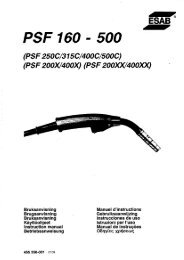
<strong>WO</strong><strong>100</strong>2<br />
Aristot<br />
Instruction manual<br />
0444 534 074 GB 071107<br />
Valid for program version 1.6
1 INTRODUCTION ................................................... 3<br />
1.1 Selection of language ...................................................... 3<br />
1.2 Control panel ............................................................. 4<br />
2 SETTING RANGE .................................................. 5<br />
3 WELDING PARAMETERS ........................................... 6<br />
3.1 Sectors .................................................................. 6<br />
3.2 Welding current ........................................................... 7<br />
3.2.1 Pulsed current/continuous current ....................................... 7<br />
3.3 Wire feed ................................................................. 7<br />
3.4 Rotation .................................................................. 8<br />
3.5 Gas ..................................................................... 8<br />
3.6 Preheating ................................................................ 8<br />
3.7 Slope .................................................................... 9<br />
4 MENU STRUCTURE ................................................ 10<br />
5 MENUS ........................................................... 11<br />
5.1 Weld area ................................................................ 11<br />
5.1.1 Parameters .......................................................... 11<br />
5.1.2 File manager ......................................................... 16<br />
5.1.3 Information ........................................................... 16<br />
5.1.4 Joint information ...................................................... 17<br />
5.1.5 Settings ............................................................. 19<br />
5.1.6 Limits ............................................................... 20<br />
5.2 Design area .............................................................. 20<br />
5.3 Settings .................................................................. 21<br />
5.3.1 Appearance .......................................................... 21<br />
5.3.2 Users settings ........................................................ 22<br />
5.4 Login .................................................................... 24<br />
5.5 Library ................................................................... 24<br />
5.5.1 Weld programs ....................................................... 25<br />
5.5.2 Search filter .......................................................... 25<br />
5.6 Manual mode ............................................................. 26<br />
5.6.1 Motor selection ....................................................... 26<br />
5.6.2 Gas valve control ..................................................... 27<br />
5.6.3 Run motor ........................................................... 27<br />
5.7 Tool editor ................................................................ 27<br />
5.7.1 Load/save ........................................................... 28<br />
5.7.2 Edit settings .......................................................... 29<br />
5.7.3 Edit motor data ....................................................... 29<br />
5.8 Logs ..................................................................... 30<br />
5.8.1 Event log ............................................................ 30<br />
5.8.2 Quality data .......................................................... 33<br />
5.9 Manual welding ........................................................... 34<br />
5.10 Generate ................................................................. 37<br />
6 TECHNICAL TERMS ................................................ 38<br />
ORDERING NUMBER .................................................<br />
39<br />
Rights reserved to alter specifications without notice.<br />
TOCe<br />
- 2 -
GB<br />
1 INTRODUCTION<br />
The manual describes the use of a control panel. <strong>WO</strong><strong>100</strong>2<br />
For general information about operation, see the instruction manual for the power<br />
source and control unit.<br />
The text displayed in the panel is available in the following languages: Swedish,<br />
Norwegian, Danish, Finnish, English, German, French, Dutch, Spanish, Italian,<br />
Portuguese, Greek, Polish, Czech, Hungarian, Slovenian and Russian.<br />
1.1 Selection of language<br />
The first time you start up the machine, the following is displayed.<br />
On delivery the system is set to English. To select your preferred language:<br />
S Press the ”Menu” button<br />
so that the menu is<br />
activated and shows the<br />
options available at this<br />
level.<br />
S Turn the knob until<br />
”Settings” is highlighted,<br />
then press the knob.<br />
S ”Appearance” is<br />
highlighted, press the knob.<br />
S ”General” is highlighted,<br />
press the knob. The<br />
”Language” field with the<br />
word ”English” is framed.<br />
Turn the knob to select<br />
your preferred language.<br />
S Activate your preferred language by pressing the knob.<br />
bi16d1ea<br />
- 3 -
GB<br />
1.2 Control panel<br />
1 Knob<br />
bi16d1ea<br />
For moving, activating and setting parameter values.<br />
There are three knob functions:<br />
S Turn to the left<br />
S Turn to the right<br />
S Press the knob, activate<br />
2 Display<br />
There are four view fields in the<br />
display:<br />
Upper status field (A)<br />
Information about the weld area’s<br />
program name, user, which type of tool<br />
is connected and the tube dimension.<br />
Main menu field (B)<br />
Different menus, see chapter 5 ”Menu<br />
Structure”.<br />
View field (C)<br />
For editing weld programs, saving programs, information, appearance, etc.<br />
Status field (D)<br />
Shows general information, error messages and current welding data (position,<br />
voltage, current)<br />
- 4 -
GB<br />
3 Quick stop/Restart<br />
bi16d1ea<br />
Immediate stop of the welding process. Gas postflow occurs according<br />
to information from end sector.<br />
Pressing the button again initiates restart with parameters from start<br />
sector; the welding process continues from the point in the weld<br />
program at which the interruption occurred.<br />
4 Left arrow<br />
Moving to the left in the menus and back in the main menus<br />
5 Right arrow<br />
Moving to the right in the menus and forward in the main menus<br />
6 Main menu<br />
Moving to the main menu field<br />
2 SETTING RANGE<br />
Parameter Setting range<br />
Sector<br />
Breakpoints<br />
Degrees<br />
Welding current 1)<br />
Peak current<br />
Background current<br />
Pulse time<br />
Background time<br />
Wire feed<br />
Peak wire feed speed<br />
Background wire feed speed<br />
Rotation<br />
Rotation speed<br />
Rotation direction<br />
Pulsed rotation<br />
Gas<br />
Weld gas preflow time<br />
Weld gas postflow time<br />
Start gas<br />
Root gas<br />
- 5 -<br />
0--50<br />
0.000 -- 9.999<br />
0 -- 3599˚<br />
3 -- 400 A 2)<br />
3 -- 400 A 2)<br />
0.01 -- 25 s<br />
0.01 -- 25 s<br />
15 -- 250 cm/min<br />
15 -- 250 cm/min<br />
5 -- <strong>100</strong> % of the welding tool’s maximum speed<br />
Forwards and Backwards<br />
0.05 -- 25 s<br />
0 -- 6000 s<br />
0 -- 6000 s<br />
0 -- 6000 s<br />
0 -- 6000 s<br />
Preheating<br />
Preheating time 0 -- 600 s<br />
Slope<br />
Slope up time<br />
Slope down time<br />
0.1 -- 25 s<br />
0.1 -- 25 s
GB<br />
1) The maximum welding current for air--cooled tube welding tools is <strong>100</strong> A.<br />
The maximum welding current for water--cooled tube welding tools is 400 A.<br />
See also the instruction manual for the tube welding tool in question.<br />
2) Depends on power source<br />
3 WELDING PARAMETERS<br />
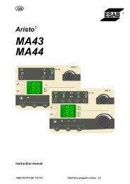
3.1 Sectors<br />
A program for tube welding can be divided into different sections: sectors. Each<br />
sector corresponds to one section of the tube’s circumference. The maximum<br />
number of sectors for one program is 50.<br />
A sector can be assigned g its own set of values<br />
ffor diff different welding ldi parameters, suchh as<br />
current current, rotation speed and wire feed speed speed, etc etc.<br />
This allows the welding to be performed using<br />
different weldingg parameter p settings g for different<br />
Sector 4 Sector 1<br />
sections of the tube joint. Sector 3 Sector 2<br />
The division into sectors is done by<br />
indicating different breakpoints or degrees<br />
around the circumference of the tube. Each<br />
breakpoint or degree constitutes the starting<br />
point for a new sector. In the figure,<br />
breakpoint 0.000, 0 degrees, is the starting<br />
point for sector 1, breakpoint 0.250, 90<br />
degrees, the starting point for sector 2, and<br />
so on on.<br />
The power source allows welding of up to<br />
10 turns t in i the th same weld ld jjoint. i t (Th (The<br />
welding tool can be rotated 10 times around<br />
the tube.)<br />
bi16d1ea<br />
- 6 -<br />
0.000<br />
Sector 4 Sector 1<br />
0.750 0.250<br />
Sector 3 Sector 2<br />
0.500<br />
Note: A sector may not be less than 10 thousandths, or 3.6 degrees, of a turn.<br />
S Turn 1 =<br />
breakpoints 0.000 -- 0.999<br />
0 -- 359 degrees<br />
S Turn 3 =<br />
breakpoints 2.000 -- 2.999<br />
720 -- 1079 degrees<br />
S Turn 5=<br />
breakpoints 4.000 -- 4.999<br />
1440 -- 1799 degrees<br />
S Turn 7=<br />
breakpoints 6.000 -- 6.999<br />
2160 -- 2519 degrees<br />
S Turn 9=<br />
breakpoints 8.000 -- 8.999<br />
2880 -- 3239 degrees<br />
S Turn 2 =<br />
breakpoints 1.000 -- 1.999<br />
360 -- 719 degrees<br />
S Turn 4 =<br />
breakpoints 3.000 -- 3.999<br />
1080 -- 1439 degrees<br />
S Turn 6=<br />
breakpoints 5.000 -- 5.999<br />
1800 -- 2159 degrees<br />
S Turn 8 =<br />
breakpoints 7.000 -- 7.999<br />
2520 -- 2879 degrees<br />
S Turn 10 =<br />
breakpoints 9.000 -- 9.999<br />
3240 -- 3599 degrees
GB<br />
To conclude a weld program, a so--called end sector is indicated.<br />
For a sector to be counted as an end sector the following two conditions must be<br />
fulfilled:<br />
S There is no subsequent sector.<br />
S The welding current value for the sector is 0 ampere.<br />
3.2 Welding current<br />
Six parameters are represented in the parameter group for welding current:<br />
S Peak current<br />
S Background current<br />
S Pulse time<br />
S Background time<br />
S Special pulsing<br />
S Slope, see point 3.7.<br />
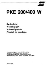
TIG welding with pulsed current<br />
bi16d1ea<br />
Pulse time<br />
Background time<br />
Background current<br />
Welding current can be pulsed or continuous (not pulsed).<br />
- 7 -<br />
Peak current<br />
3.2.1 Pulsed current/continuous current<br />
When welding using a pulsed current, peak current, background current, pulse<br />
time and background time must be given a value.<br />
When welding using a continuous current, however, you need only enter a<br />
parameter value for peak current. Entering a value for background current will result<br />
in a pulsed current.<br />
3.3 Wire feed<br />
Wire feed speed is used to indicate the feed speed for the filler wire in cm/minute.<br />
Speed can be pulsed or continuous (not pulsed).<br />
Three parameters are represented in the parameter group for wire feed:<br />
S Peak wire feed<br />
S Background wire feed<br />
S Slope, see point 3.7.<br />
For welding using a continuous (not pulsed) wire feed, only the peak wire feed<br />
parameter needs to be entered.
GB<br />
For welding with a pulsed wire feed speed, both the peak wire feed and the<br />
background wire feed parameters need to be entered.<br />
The pulsed wire feed speed is always automatically synchronized with the welding<br />
current so that the wire feed speed is high when using peak current and low when<br />
using background current.<br />
3.4 Rotation<br />
Used to indicate the rotation speed of the electrode around the workpiece. It is<br />
indicated in mm/min.<br />
The rotation speed can be pulsed or continuous (not pulsed).<br />
Four parameters are represented in the parameter group for rotation:<br />
S Rotation speed<br />
S Rotation direction<br />
S Pulsed rotation<br />
S Slope, see point 3.7.<br />
Pulsed rotation is automatically synchronized with the welding current so that the<br />
welding tool is stationary at peak current and rotates at background current.<br />
3.5 Gas<br />
Three parameters are represented in the parameter group for shielding gas:<br />
S Weld gas<br />
S Start gas<br />
S Root gas<br />
Weld gas refers to the shielding gas on the upper side of the weld joint. The weld<br />
gas parameter indicates how long the shielding gas is to flow on the upper side of<br />
the joint before and after welding. The weld gas is monitored by a flow guard min.<br />
4.5 l/min.<br />
Some shielding gases, for example, helium (He), can cause problems with regard to<br />
igniting the arc. If this type of shielding gas is to be used as weld gas, it may be<br />
advisable to use a different gas mixture at the actual instance of starting, a so--called<br />
start gas.<br />
Root gas refers to the shielding gas on the underside of the weld joint. The root gas<br />
parameter indicates how long the shielding gas is to flow on the underside of the<br />
joint before and after welding.<br />
If one value is entered for weld gas and another for start gas in sector 1, only the<br />
start gas will flow. The weld gas starts flowing once the arc is ignited.<br />
3.6 Preheating<br />
Preheating is used to heat the workpiece at the starting point in order to ensure<br />
correct penetration of the molten pool and is defined as the time elapsing between<br />
arc ignition and the start of the rotary motion. If no value has been entered for<br />
preheating, rotation will start as soon as the arc ignites.<br />
bi16d1ea<br />
- 8 -
GB<br />
3.7 Slope<br />
A slope may be indicated for certain parameters. A slope is the time during which the<br />
value of the parameter gradually changes from the value in the preceding sector to<br />
the value entered for the current sector.<br />
Slope up = gradual increase, if the preceding value is lower than the entered value.<br />
Slope down = gradual decrease, if the preceding value is higher than the entered<br />
value.<br />
The maximum period a slope can run depends on the duration of a particular sector.<br />
If the slope time is of the same duration as the sector, this is called a ‘sector slope’.<br />
bi16d1ea<br />
- 9 -
GB<br />
4 MENU STRUCTURE<br />
Table<br />
· Edit table<br />
· Show/hide<br />
· Weld<br />
control<br />
· Edit<br />
Table<br />
· Edit table<br />
· Show/hide<br />
· Edit<br />
bi16d1ea<br />
Weld area<br />
Parameters File manager Information Joint info. Settings Limits<br />
Graphical<br />
· Current<br />
· Wire feed<br />
· Rotation<br />
· Gas<br />
· General<br />
· Description<br />
· Tube<br />
· Electrode<br />
· Wire<br />
· Gas<br />
Design area<br />
- 10 -<br />
· Visualization<br />
· Parameter<br />
values<br />
· Tool<br />
settings<br />
· Tube<br />
settings<br />
Parameters File manager Information Joint info. Settings Limits<br />
Graphical<br />
· Current<br />
· Wire feed<br />
· Rotation<br />
· Gas<br />
· General<br />
· Description<br />
· Tube<br />
· Electrode<br />
· Wire<br />
· Gas<br />
· Visualization<br />
· Parameter<br />
values<br />
· Tool<br />
settings<br />
· Tube<br />
settings
GB<br />
bi16d1ea<br />
Settings Login Library Manual<br />
mode<br />
Appearance User · Weld<br />
program<br />
· General<br />
· Quality<br />
data<br />
Load/<br />
save<br />
· Tool<br />
selection<br />
· Tool<br />
action<br />
Tool<br />
editor<br />
Change<br />
settings<br />
· General<br />
· Parameter<br />
limits<br />
5 MENUS<br />
Change<br />
motor data<br />
· Change<br />
parameter<br />
· Show para<br />
meters<br />
- 11 -<br />
· Motor selection<br />
· Gas valve control<br />
· Search filter · Run motor<br />
Event<br />
log<br />
Logs Manual<br />
welding<br />
Quality data<br />
· Quality data<br />
files<br />
· Contents<br />
Generate<br />
There are two work areas where you can view and edit welding parameters, Weld<br />
area (see chapter 5.1) and Design area (see chapter 5.2).<br />
5.1 Weld area<br />
In this view, you can view and edit parameters in a weld program and control the<br />
welding process. The weld program in the weld area controls the welding process.<br />
You can enter the weld area’s parameters by loading a weld program from the<br />
library, generating a basic weld program or editing the parameters manually.<br />
5.1.1 Parameters<br />
This menu option is solely an archive for other menu options.<br />
Weld area - -> Parameters - -> Table<br />
Here you can view and edit welding parameters in table form and start and stop the<br />
welding process.
GB<br />
Each parameter in a parameter group is highlighted in the group’s colour.<br />
A selected welding parameter in the table is indicated by a blue box with two arrows.<br />
S To move through the table, turn the knob.<br />
S To change direction, press the knob.<br />
S To change a parameter value, click on the right arrow and change the parameter<br />
values using the knob.<br />
Menu shortcuts:<br />
S Edit table<br />
Highlights the table with welding parameters<br />
S Show/hide<br />
Shows or hides groups of welding parameters in the table.<br />
Here you can choose which parameters are to be shown in the table by selecting<br />
groups of parameters.<br />
S Weld control<br />
Highlights the start button in the weld control box.<br />
The buttons in this box control the welding process. You can start, stop, direct<br />
stop, continue or simulate the start of the welding process.<br />
S Edit sectors<br />
Highlights the button ’Add sector after’ in the Edit sectors box.<br />
The number of sectors can be increased or decreased using this box. It is<br />
possible to add new sectors before or after an existing sector and remove<br />
sectors in the weld program.<br />
bi16d1ea<br />
- 12 -
GB<br />
Weld area - -> Parameters - -> Graphical - -> Current<br />
In this view, you can view and edit welding parameters for current in a graphical<br />
representation.<br />
The current’s peak and background values are represented in a coordinate system.<br />
The Y--axis represents the current’s value in ampere, while the X--axis represents<br />
time.<br />
The current’s various values per sector are connected and form a line.<br />
Green indicates the peak current value per sector, while blue indicates the<br />
background current value per sector.<br />
Slope is represented as an angled line from the start of the sector, which ends where<br />
the slope time stops on the X--axis.<br />
S Zoom<br />
Here you can adjust the scale of the X--axis in the coordinate system.<br />
S Weld control<br />
The buttons in this box control the welding process. You can start, stop, direct<br />
stop, continue or simulate the start of the welding process.<br />
S Sector information<br />
The figures in this field show the other parameters concerned with the parameter<br />
group for current. The sector’s breakpoint is represented by a dash in a circle<br />
(cross--section of a tube).<br />
If the weld program extends over more than one turn, these turns are shown as<br />
a sequence of slightly smaller circles.<br />
The preheating time is shown in tenths of a second under the breakpoint<br />
information.<br />
Special pulsing on or off is shown as an image, where a red cross indicates that<br />
special pulsing is not being used.<br />
The relationship between pulse times is shown as a pulse cycle. Separate times<br />
for peak and background pulse.<br />
bi16d1ea<br />
- 13 -
GB<br />
S Figure for breakpoints<br />
It is possible to move, add or remove breakpoints using the knob in the figure for<br />
breakpoints. By skipping forward to the figure and highlighting it, you can turn the<br />
knob and move a white dash or ‘cursor’.<br />
Moving a breakpoint:<br />
S Press the knob once the cursor is on or directly next to the breakpoint cursor<br />
(black) to be moved.<br />
The breakpoint is ‘collected’ by the cursor and follows this when it is turned<br />
around in the circle.<br />
S To confirm the new breakpoint, press the knob.<br />
Creating a new breakpoint<br />
S Move the cursor by turning the knob and press the knob once at the point<br />
where you want the new breakpoint to be created.<br />
Removing a breakpoint:<br />
S Press the knob once the cursor is on or directly next to the breakpoint cursor<br />
to be removed.<br />
The breakpoint is ‘collected’ by the cursor and follows this when it is turned<br />
around in the circle.<br />
S Turn the knob to the previous or next breakpoint and press the knob once.<br />
Weld area - -> Parameters - -> Graphical - -> Wire feed<br />
Here you can view and edit parameters that control wire feed per sector.<br />
The coordinate system shows the speed at which the wire will be fed out at the peak<br />
and background value per sector.<br />
Slope is represented as an angled line from the start of the sector for the duration<br />
entered for the slope.<br />
bi16d1ea<br />
- 14 -
GB<br />
Weld area - -> Parameters - -> Graphical - -> Rotation<br />
Rotation speed is viewed and edited in a coordinate system with one line for each<br />
value and time slope. The coordinate system shows breakpoints as dashed lines.<br />
If pulsed rotation is off, this is shown by a pulse that is crossed out.<br />
Weld area - -> Parameters - -> Graphical - -> Gas<br />
Times for weld, start and root gas are viewed and edited in this view.<br />
bi16d1ea<br />
- 15 -
GB<br />
5.1.2 File manager<br />
This view is used to save, copy, clear and verify weld programs.<br />
S Save weld program<br />
To save a weld program, select where you want the program to be saved, either<br />
on the control unit (User defined programs) or on a USB memory device<br />
(External memory).<br />
Specify a file name and click the ’Save weld program’ button using the knob.<br />
S Copy weld program to another area<br />
Depending on which work area is active, it is possible to copy the contents of<br />
one area to another area by clicking the ’Copy this wld program to design area’<br />
button or ’Copy this weld program to weld area’ button.<br />
S Clear, reset weld program<br />
If you want to begin a brand new weld program, click the ’Clear weld area’<br />
button or ’Clear design area’ button.<br />
S Verify<br />
This function is used to check whether the weld program in the current work area<br />
fulfils the system’s requirements as follows:<br />
S A tool is selected for the weld program.<br />
S The connected tool is the same as the one the program is designed for (only<br />
applies to weld area).<br />
S The program has at least two sectors (start and stop sector).<br />
S The final sector in the program is a stop sector (the welding current is zero).<br />
S Selected tube diameter is supported by the selected tool.<br />
S The welding parameters in each sector are within the limits (min. and max.<br />
values) for the selected tool.<br />
5.1.3 Information<br />
Used to enter information about the weld program. This information does not affect<br />
the welding process, but is an aid for describing the program in words.<br />
bi16d1ea<br />
- 16 -
GB<br />
S General<br />
Program name is shown at the top of the list. This is not the same as file name in<br />
file manager. If a program name is assigned, this is the suggestion offered for<br />
the file name.<br />
S Description<br />
S Tube<br />
S Electrode<br />
S Wire<br />
S Gas<br />
5.1.4 Joint information<br />
In this view, you can view and change how the joint will look to suit the weld<br />
program. This is only information about the weld program. It does not affect the<br />
welding process.<br />
In the ”Visualization, Visualization” field, it is possible to view a graphical<br />
representation of the joint. In the ”Parameters” field, you can view those values<br />
relevant to the joint. Values that affect the joint can be changed in both fields.<br />
bi16d1ea<br />
- 17 -
GB<br />
Visualization<br />
S Turn the knob and a blue line will indicate which parameter has been selected.<br />
S Press the knob and the line will turn red. The value can be changed by turning<br />
the knob.<br />
Parameter<br />
S Use the arrows to move between the various parameters.<br />
S Turn the knob to change the value.<br />
Gap<br />
Nose<br />
Nose length<br />
bi16d1ea<br />
- 18 -
GB<br />
Radius<br />
Bevel angle<br />
Material thickness<br />
5.1.5 Settings<br />
This view allows you to select tools and the external tube dimension for which the<br />
weld program has been created. In the ”Tool settings” field, you can scroll through<br />
the tools and look at an overview of the tools under ”Tool illustration”. To select a<br />
tool, press the knob and then select the type of tool by turning and pressing the<br />
knob.<br />
The external tube dimension is selected by turning the knob. To confirm, press the<br />
knob. The selected tool (”Tool ”) and dimension (”Ø:”) are visible in the top status<br />
field, when using views from a work area.<br />
bi16d1ea<br />
- 19 -
GB<br />
5.1.6 Limits<br />
This view can be used to limit how much a user can change preset parameter values<br />
in a weld program.<br />
In order for the restrictions to be activated, the check box ”Limits activated” must be<br />
checked.<br />
5.2 Design area<br />
Weld programs can be created in the design area for use in the weld area or saved<br />
in the library for subsequent use. To see how the design area works, refer to chapter<br />
5.1Weld Area. The design area works in a similar way to the weld area.<br />
The greatest difference between the two areas is that you cannot control the welding<br />
process from the design area.<br />
bi16d1ea<br />
- 20 -
GB<br />
5.3 Settings<br />
You can change the appearance of the panel and manage users in the system via<br />
the Settings menu.<br />
5.3.1 Appearance<br />
Settings - -> Appearance - -> General<br />
S Language<br />
Choose from Swedish, Norwegian, Danish, Finnish, English, German, French,<br />
Dutch, Spanish, Italian, Portuguese, Greek, Polish, Czech, Hungarian, Slovenian<br />
and Russian.<br />
S Angle system<br />
Choose between thousandth points or degrees.<br />
bi16d1ea<br />
- 21 -
GB<br />
S Start view<br />
Choose between starting the panel with the login menu or last viewed menu.<br />
Settin g s - - > Ap p earan ce - - > QData<br />
S Post weld function<br />
Choose from:<br />
S None<br />
S Print<br />
S Save<br />
S Print + save<br />
The values that are saved and printed out are set values and the measurement<br />
values from the concluded welding process. Printing uses the integral printer in<br />
the control unit.<br />
The values are saved in the control panel under the ”quality data” menu, see<br />
chapter 5.8.<br />
Settings - -> Appearance - -> Date and time<br />
Here you can view and enter the<br />
date and time used in the system.<br />
5.3.2 Users settings<br />
In this view, you can add, change and delete users.<br />
bi16d1ea<br />
- 22 -
GB<br />
”Default user” appears the first time this menu is accessed.<br />
To add a new user:<br />
S Press the right or left arrow until ”New user” is<br />
highlighted.<br />
S Press the knob.<br />
S Turn the knob until a suitable ID appears.<br />
S Press the knob. The next box will be<br />
highlighted.<br />
S Turn the knob until a suitable letter appears,<br />
press the knob, and so on.<br />
S Once the name is ready, press the right<br />
arrow until ”ok” is highlighted.<br />
S Press the knob.<br />
A new user appears in the list.<br />
To change a user:<br />
S Highlight the user list (by pressing the arrow keys).<br />
S Turn the knob to select the user you want to change and press the knob.<br />
A new field appears at the side of the user list, which allows you to change the<br />
selected user’s name or ID. Confirm the changes using ”OK”.<br />
To delete a user:<br />
S Highlight the user.<br />
S Press the knob, move to the ”Delete user” button and click on the button.<br />
The user disappears from the list.<br />
bi16d1ea<br />
- 23 -
GB<br />
5.4 Login<br />
The login menu is used to select users and view which program version applies for<br />
the panel and which units are connected. It is also possible to view version<br />
information on the connected units/nodes.<br />
The user name is shown in the top status field, see chapter Control Panel 1.2.<br />
5.5 Library<br />
Programs can be erased and retrieved for the weld area or the design area using the<br />
library menu.<br />
Please note that each program stored in the library is 4 -- 6 Kb. The control unit’s<br />
internal memory is 1 Gb, so there is only a very small risk of the library becoming full.<br />
NOTE! Predefined programs that begin with <strong>ESAB</strong> cannot be erased. These<br />
programs are tested and are intended to serve as start data for similar dimensions.<br />
bi16d1ea<br />
- 24 -
GB<br />
5.5.1 Weld programs<br />
5.5.2 Search filter<br />
Using the search filter menu it is possible to search by the following criteria in the<br />
programs stored in the library:<br />
S Nothing<br />
S Name<br />
S Project<br />
S Material<br />
S External tube diameter<br />
S Tube wall thickness<br />
If there are programs that match the criteria, these programs are displayed in the<br />
”Weld programs” menu.<br />
If there are no programs that match the selected criteria, continue on to ”Go to<br />
Generate”, see chapter Generate 5.10.<br />
bi16d1ea<br />
- 25 -
GB<br />
5.6 Manual mode<br />
All motors can be checked using this menu.<br />
5.6.1 Motor selection<br />
Here you can choose which motor to run and also enter the motor speed.<br />
Note: This view only shows those motors available in the system. The tool selected<br />
in ”Weld area ----> Settings” affects the information shown.<br />
S Wire inching<br />
Used when loading a new wire bobbin, for example.<br />
S Rotation/Transport<br />
Used to move the welding tool around the workpiece.<br />
bi16d1ea<br />
- 26 -
GB<br />
5.6.2 Gas valve control<br />
Used when measuring the gas flow or to flush any air or moisture from the gas<br />
hoses before welding begins.<br />
Starts and stops the flow of gas.<br />
If you exit this view, the gas valves close automatically.<br />
5.6.3 Run motor<br />
Used to view the current value of the motors.<br />
Note! Hold in the knob to activate motor drive.<br />
Run selected motor forwards ”+” or<br />
backwards ”--”, and view current<br />
speed for selected motor.<br />
5.7 Tool editor<br />
This menu is used for viewing and editing tool parameters. You can create new tools<br />
from scratch or use predefined tools. Tools that are created by a user can be<br />
removed, changed and saved. Predefined tools supplied with the system cannot be<br />
changed or removed.<br />
Please note that the tool currently being used is designated a specific work area, a<br />
tool area. All changes performed in the views described below only affect the tool<br />
area and are not saved until this is requested by the user.<br />
bi16d1ea<br />
- 27 -
GB<br />
5.7.1 Load/save<br />
In this view, you can load a tool to work from when creating a new tool, clear<br />
user--defined tools and save tools.<br />
Select a tool to use (enter parameters in the tool area) by moving to the list of tools<br />
using the left or right arrow. Turn the knob to select (highlight) a tool.<br />
Move to the button ”Load tool”, press the knob and confirm that this is the tool you<br />
want to use.<br />
It is also possible to use a tool specification (tool type), for example, a tool with a<br />
particular diameter range.<br />
Delete a created tool by selecting it in the list, press the knob on ”Delete tool, Delete<br />
tool” and confirm that you want to delete it using ”Yes”. It is not possible to delete any<br />
tools supplied with the system.<br />
You can save the created tool as a new tool or in place of an existing tool (you<br />
cannot replace tools supplied with the system).<br />
To save the tool as a new tool (or new tool type):<br />
S Move to the list of tools (or tool types) using the arrow keys.<br />
S Turn the knob to highlight ”New.... ” in the list.<br />
S Click the menu button and select ”Tool action”.<br />
S Move to the ”Save tooll” button.<br />
S Press the knob and confirm that you want to save the tool as a new tool using<br />
the ”Yes” button.<br />
To replace an existing tool, use the same procedure as above but instead select an<br />
existing tool from the list of tools.<br />
You can upload tools to the system from a USB memory device, if you have a<br />
”MechTIG_Tools.xml” tool file at the root of the file structure.<br />
bi16d1ea<br />
- 28 -
GB<br />
Proceed as follows:<br />
S Connect a USB memory device to the panel’s USB terminal, where the<br />
”MechTIG_Tools.xml” file is at the very root of the file structure.<br />
S Move to the ”Load tools from usb--memory” button using the arrow keys.<br />
S Press the knob and confirm using ”Yes” to invalidate all the changes made to the<br />
tool.<br />
Clear or reset all parameters in the tool area by moving to the ”Clear tooll” button<br />
and pressing the knob. Confirm using ”Yes” to invalidate any changes made in the<br />
tool area.<br />
To save all your tools to a USB memory device:<br />
S Connect a USB memory device to the panel’s USB terminal.<br />
S Move to the ”Save tools to usb--memory” button and press the knob.<br />
S Confirm using ”Yes” to save the tools and overwrite any tools stored on the USB<br />
memory device.<br />
5.7.2 Edit settings<br />
This view is used once you have loaded a tool or when you want to create a brand<br />
new tool. Here you can view and edit all parameter values for a tool.<br />
The ”General settings” field contains general settings for the tool, while the<br />
”Parameter limits” field defines the highest and lowest values for a parameter.<br />
For min. values the value 0 means that the minimum value has not been set, while<br />
for max. values 65535 means that the maximum value has not been set. (In some<br />
instances, where decimals are used, 655,30 or 6553,5 may indicate not set).<br />
5.7.3 Edit motor data<br />
In this view, you can view and edit specific motor settings. There are motor settings<br />
for each motor (rotation, wire feed, weaving and AVC). There are currently three<br />
parameters per motor. The parameters are ”Setting parameter”, ”Scalefactor<br />
position” (”numerator” and ”denominator”) and ”Scalefactor speed” (”numerator” and<br />
”denominator”).<br />
bi16d1ea<br />
- 29 -
GB<br />
Add the value <strong>100</strong> for the parameter ”Scalefactor position (numerator)” for the motor<br />
that controls rotation.<br />
Proceed as follows:<br />
S Move to the text field under ”Motor parameter” using the arrow keys.<br />
S Turn the knob until ”Scalefactor position (numerator)” is visible in the text field<br />
and press the knob.<br />
S Change the value to <strong>100</strong> by turning the knob. Press the knob to continue.<br />
S Turn the knob so that ”Rotation” appears in the text field. Confirm by pressing<br />
the knob.<br />
S Press the knob to add (or edit) the value in the list of parameters for the rotation<br />
motor.<br />
You can remove motor parameters by highlighting a parameter in the list of motor<br />
parameters, pressing the knob, moving to the ”Delete” button and pressing the knob<br />
to delete the selected parameter from the list.<br />
5.8 Logs<br />
This menu allows you to view logs compiled by the system.<br />
5.8.1 Event log<br />
Event log<br />
When a fault occurs, this is indicated by the symbol , which is displayed to the<br />
right of the <strong>ESAB</strong> logo. When you go into the Event log menu, the symbol<br />
disappears.<br />
bi16d1ea<br />
- 30 -
GB<br />
Used to display operating messages<br />
In order to clear or remove all operating messages from the log, move the focus to<br />
the ”Clear log” button with the arrow keys and press the knob. Confirm that you want<br />
to remove all events by pressing ”Yes” with the knob. The event log is reloaded and<br />
is now empty.<br />
It is also possible to save the event log onto an external USB memory.<br />
Proceed as follows:<br />
S Insert a USB memory in the panel’s USB contact, move the focus with the arrow<br />
keys to the ”Save” button.<br />
S Press the knob. The text ”Event log saved” appears in the lower status bar if the<br />
log was saved correctly.<br />
Operating messages<br />
Unit Unit<br />
1 = cooling unit 6 = motor control 1, rotation, wire feed<br />
2 = power source 8 = weld data unit<br />
4 = remote control 17 = I/O node<br />
bi16d1ea<br />
- 31 -
GB<br />
Below describes event codes which the user can take action by him self. Is any other<br />
code shown, send for a service technician.<br />
Code Description<br />
5 Intermediate DC voltage outside limits<br />
The voltage is too high or too low. Too high a voltage can be due to severe transients on<br />
the mains power supply or to a weak power supply (high inductance of the supply or a<br />
phase missing).<br />
The power unit is stopped and cannot be started.<br />
Action: Turn off the mains power supply to reset the unit. If the fault persists, send for a<br />
service technician.<br />
6 High temperature<br />
The thermal overload cut--out has tripped.<br />
The current welding process is stopped and cannot be restarted until the cut--out has<br />
reset.<br />
Action: Check that the cooling air inlets or outlets are not blocked or clogged with dirt.<br />
Check the duty cycle being used, to make sure that the equipment is not being overloaded.<br />
If the fault is repeated, send for a service technician.<br />
11 Motor servo fault, (rotation, wire feed)<br />
When a motor cannot maintain its speed. Welding stops.<br />
Action: Check that the tool / wire feed unit has not become trapped or is moving too<br />
slowly. If the fault persists, send for a service technician.<br />
11 Current servo fault, (power source)<br />
The voltage is too high or too low. Too high a voltage can be due to severe transients on<br />
the mains power supply or to a weak power supply (high inductance of the supply or a<br />
phase missing).<br />
The power unit is stopped and cannot be started.<br />
Action:Turn off the mains power supply to reset the unit. If the fault persists, send for a<br />
service technician.<br />
12 Internal communication error (warning)<br />
The load on the system’s CAN--bus is temporarily too high.<br />
The power unit may have lost contact with the panel.<br />
Action: Check that all the equipment is correctly connected.<br />
If the fault persists, send for a service technician.<br />
14 Communication error<br />
The system’s CAN--bus has temporarily stopped working due to the load being too high.<br />
The current welding process stops.<br />
Action: Check that all the equipment is correctly connected. Turn off the mains power<br />
supply to reset the unit. If the fault persists, send for a service technician.<br />
17 Lost contact with unit<br />
Lost contact with unit. The gas is not turned off; it must be turned off manually.<br />
Start is prevented<br />
Action: Check the cables. If the fault persists, send for a service technician.<br />
19 Battery voltage low<br />
Battery voltage too low. If the battery is not replaced, all stored data will be lost.<br />
This fault does not disable any functions.<br />
Action: Send for a service technician to replace the battery.<br />
20 Incorrect set values stored in welding program<br />
Non--permitted values have been discovered at start--up.<br />
Action: Change parameters in the welding program. If the fault persists, send for a service<br />
technician.<br />
bi16d1ea<br />
- 32 -
GB<br />
Code Description<br />
29 No cooling water flow<br />
The flow monitor switch has tripped.<br />
The current welding process is stopped and starting is prevented.<br />
Action: Check cooling water circuit, pump and hoses.<br />
32 No gas flow<br />
The gas flow is less than 3.5 l/min. Start prevented.<br />
Action: Check the gas valve, hoses and connectors.<br />
41 Failed welding start<br />
The power source does not manage to light the welding arc.<br />
Action: Check welding cables and tool.<br />
5.8.2 Quality data<br />
Here you can view data saved<br />
under the post weld function, see<br />
chapter 5.3.<br />
Logs - -> QData - -> QData files<br />
The QData file is saved with the<br />
date and a serial number.<br />
ThefilescanbesavedtoaUSB<br />
memory device using ”Save”.<br />
Logs - -> QData - -> QData content<br />
The QData file’s set values and<br />
measurement values are visible in<br />
this field.<br />
bi16d1ea<br />
- 33 -
GB<br />
5.9 Manual welding<br />
This menu is used for welding performed with a manual TIG torch.<br />
Trigger mode<br />
bi16d1ea<br />
2stroke<br />
Gas preflow Slope<br />
up<br />
Functions when using 2 -stroke control of the welding torch.<br />
- 34 -<br />
Slope down Gas postflow<br />
In 2--stroke control mode, pressing the TIG torch trigger switch (1) starts gas preflow<br />
(if used) and ignites the arc. The current rises to the set value (as controlled by the<br />
slope up function, if in operation). Releasing the trigger switch (2) reduces the<br />
current (as controlled by the slope down function, if in operation) and extinguishes<br />
the arc. Gas postflow follows, if in operation.
GB<br />
bi16d1ea<br />
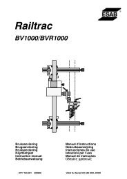
4stroke<br />
Gas preflow Slope<br />
up<br />
Functions when using 4 -stroke control of the welding torch.<br />
- 35 -<br />
Slope down Gas postflow<br />
In 4--stroke control mode, pressing the trigger switch (1) starts gas preflow (if used).<br />
At the end of the gas preflow time, the current rises to the pilot level (a few<br />
amperes), and the arc is ignited. Releasing the trigger switch (2) increases the<br />
current to the set value (as controlled by the slope up function, if in operation). When<br />
the trigger switch is next pressed (3), the current is reduced to pilot level again (as<br />
controlled by the slope down function, if in operation). Releasing the switch again (4)<br />
extinguishes the arc and starts gas postflow.<br />
Start method<br />
HF<br />
The HF function ignites the arc by means of a spark produced when the electrode is<br />
brought closer to the workpiece.<br />
LiftArct<br />
The LiftArct function ignites the arc when the electrode is brought into contact with<br />
the workpiece and then lifted away from it.<br />
Igniting the arc using the LiftArc functiont. Step 1: the electrode is held against the workpiece. Step<br />
2: the trigger switch is pressed, and a low current starts to flow. Step 3: the welder lifts the electrode<br />
from the workpiece; the arc ignites, and the current rises automatically to the set value.
GB<br />
Peak current<br />
The higher of two current values in the event of pulsed current.<br />
Background current<br />
The lower of two current values in the event of pulsed current.<br />
Peak time<br />
The time the pulse current is on during a pulse period.<br />
Background time<br />
Background current time that together with the pulse current time produces the pulse<br />
period.<br />
TIG welding with pulsed current<br />
bi16d1ea<br />
Pulse time<br />
Background time<br />
Background current<br />
- 36 -<br />
Peak current<br />
Slope up<br />
The slope up function means that when the TIG arc ignites the current rises slowly to<br />
the set value. This provides ‘gentler’ heating of the electrode, and gives the welder a<br />
chance to position the electrode properly before the full current value is reached.<br />
Slope down<br />
TIG welding uses ”slope down”, where the current falls slowly over a controlled time,<br />
to avoid craters and/or cracks in a completed weld.<br />
Gas preflow<br />
This controls the time during which shielding gas flows before the arc is ignited. Also<br />
see information under chapter 3.5.<br />
Gas postflow<br />
This controls the time during which shielding gas flows after the arc is extinguished.<br />
Also see information under chapter 3.5.
GB<br />
5.10 Generate<br />
A complete basic weld program can be generated here that can be added to the<br />
design area or directly to the weld area. The program can be used as the basis for<br />
creating your own program.<br />
Specify:<br />
S Tube material<br />
S Tube wall thickness<br />
Max. 3 mm for stainless steel and max. 2.7 mm for carbon steel.<br />
S External tube diameter<br />
S Tool and tool type<br />
Activate by pressing ”Generate in weld area” or ”Generate in design area”.<br />
Automatically opens the weld area or design area menu.<br />
It is now possible to continue working on the program in the weld area or design<br />
area. See chapter ”Weld Area” 5.1 or ”Design Area” 5.2.<br />
bi16d1ea<br />
- 37 -
6 TECHNICAL TERMS<br />
2stroke 2--stroke control of the welding torch.<br />
4stroke 4--stroke control of the welding torch.<br />
Amplitude Weave.<br />
Background current The lower of two current values when using pulsed current.<br />
Background time Background current time that together with the peak current time produces<br />
the pulse period.<br />
Background voltage Arc voltage control when using background current.<br />
Background wire feed<br />
speed<br />
Wire feed speed during specified background time.<br />
Breakpoint Starting point for a new sector.<br />
Delay time The time it takes for the arc voltage to stabilize before arc voltage control<br />
begins.<br />
Design area Weld programs are created in this menu.<br />
End sector Last welding sector in a welding sequence.<br />
Generate Search for a complete basic weld program.<br />
Library Memory for storing weld programs.<br />
Peak current The higher of two current values when using pulsed current, or the current<br />
value when using continuous current.<br />
Peak voltage Arc voltage control at peak current.<br />
Peak wire feed speed Wire feed speed at peak current.<br />
Preheating time Delay time for welding movement when preheating the workpiece.<br />
Pulse time The time the current is ”on” during a pulse period.<br />
Root gas Shielding gas for the underside of the weld joint (root side).<br />
Rotation speed The rotation speed of the electrode around the workpiece.<br />
Sector A specific section of tube.<br />
Sector system How the division into sectors is displayed, by degrees or breakpoints.<br />
Slope down Gradual reduction of a value.<br />
Slope up Gradual increase in a value.<br />
Special pulsing Welding current synchronizes with the weaving motion.<br />
Square -wave pulsing Special pulsing with pulsed rotation.<br />
Start gas Special shielding gas with high ionizing qualities, which facilitates arc<br />
ignition.<br />
Start sector First welding sector in a welding sequence.<br />
Verify Check whether the program stays within the limit values.<br />
Weld area Programs in the weld area control the welding process.<br />
Weld gas Shielding gas for the upper side of the weld joint.<br />
bi16d1eb<br />
- 38 -
Ordering number<br />
Ordering no. Denomination<br />
0444 534 070 Instruction manual SE<br />
0444 534 071 Instruction manual DK<br />
0444 534 072 Instruction manual NO<br />
0444 534 073 Instruction manual FI<br />
0444 534 074 Instruction manual GB<br />
0444 534 075 Instruction manual DE<br />
0444 534 076 Instruction manual FR<br />
0444 534 077 Instruction manual NL<br />
0444 534 078 Instruction manual ES<br />
0444 534 079 Instruction manual IT<br />
0444 534 080 Instruction manual PT<br />
0444 534 081 Instruction manual GR<br />
0444 534 082 Instruction manual PL<br />
0444 534 083 Instruction manual HU<br />
0444 534 084 Instruction manual CZ<br />
0444 534 027 Instruction manual GB, RU<br />
Instruction manuals and the spare parts list are available on the Internet at www.esab.com<br />
bi16o2<br />
- 39 -<br />
Edition 071107
<strong>ESAB</strong> subsidiaries and representative offices<br />
Europe<br />
AUSTRIA<br />
<strong>ESAB</strong> Ges.m.b.H<br />
Vienna -Liesing<br />
Tel: +43 1 888 25 11<br />
Fax: +43 1 888 25 11 85<br />
BELGIUM<br />
S.A. <strong>ESAB</strong> N.V.<br />
Brussels<br />
Tel: +32 2 745 11 00<br />
Fax: +32 2 745 11 28<br />
THE CZECH REPUBLIC<br />
<strong>ESAB</strong> VAMBERK s.r.o.<br />
Vamberk<br />
Tel: +420 2 819 40 885<br />
Fax: +420 2 819 40 120<br />
DENMARK<br />
Aktieselskabet <strong>ESAB</strong><br />
Herlev<br />
Tel:+4536300111<br />
Fax:+4536304003<br />
FINLAND<br />
<strong>ESAB</strong> Oy<br />
Helsinki<br />
Tel: +358 9 547 761<br />
Fax: +358 9 547 77 71<br />
FRANCE<br />
<strong>ESAB</strong> France S.A.<br />
Cergy Pontoise<br />
Tel:+33130755500<br />
Fax:+33130755524<br />
GERMANY<br />
<strong>ESAB</strong> GmbH<br />
Solingen<br />
Tel: +49 212 298 0<br />
Fax: +49 212 298 218<br />
GREAT BRITAIN<br />
<strong>ESAB</strong> Group (UK) Ltd<br />
Waltham Cross<br />
Tel: +44 1992 76 85 15<br />
Fax: +44 1992 71 58 03<br />
<strong>ESAB</strong> Automation Ltd<br />
Andover<br />
Tel: +44 1264 33 22 33<br />
Fax: +44 1264 33 20 74<br />
HUNGARY<br />
<strong>ESAB</strong> Kft<br />
Budapest<br />
Tel:+3612044182<br />
Fax:+3612044186<br />
ITALY<br />
<strong>ESAB</strong> Saldatura S.p.A.<br />
Mesero (Mi)<br />
Tel:+3902979681<br />
Fax:+390297289181<br />
THE NETHERLANDS<br />
<strong>ESAB</strong> Nederland B.V.<br />
Amersfoort<br />
Tel: +31 33 422 35 55<br />
Fax: +31 33 422 35 44<br />
NORWAY<br />
AS <strong>ESAB</strong><br />
Larvik<br />
Tel:+473312<strong>100</strong>0<br />
Fax:+4733115203<br />
POLAND<br />
<strong>ESAB</strong> Sp.zo.o.<br />
Katowice<br />
Tel: +48 32 351 11 00<br />
Fax: +48 32 351 11 20<br />
PORTUGAL<br />
<strong>ESAB</strong> Lda<br />
Lisbon<br />
Tel: +351 8 310 960<br />
Fax: +351 1 859 1277<br />
SLOVAKIA<br />
<strong>ESAB</strong> Slovakia s.r.o.<br />
Bratislava<br />
Tel:+421744882426<br />
Fax:+421744888741<br />
SPAIN<br />
<strong>ESAB</strong> Ibérica S.A.<br />
Alcalá de Henares (MADRID)<br />
Tel: +34 91 878 3600<br />
Fax: +34 91 802 3461<br />
SWEDEN<br />
<strong>ESAB</strong> Sverige AB<br />
Gothenburg<br />
Tel:+4631509500<br />
Fax:+4631509222<br />
<strong>ESAB</strong> international AB<br />
Gothenburg<br />
Tel:+4631509000<br />
Fax:+4631509360<br />
SWITZERLAND<br />
<strong>ESAB</strong> AG<br />
Dietikon<br />
Tel: +41 1 741 25 25<br />
Fax: +41 1 740 30 55<br />
North and South America<br />
ARGENTINA<br />
CONARCO<br />
Buenos Aires<br />
Tel: +54 11 4 753 4039<br />
Fax: +54 11 4 753 6313<br />
BRAZIL<br />
<strong>ESAB</strong> S.A.<br />
Contagem -MG<br />
Tel: +55 31 2191 4333<br />
Fax: +55 31 2191 4440<br />
CANADA<br />
<strong>ESAB</strong> Group Canada Inc.<br />
Missisauga, Ontario<br />
Tel: +1 905 670 02 20<br />
Fax: +1 905 670 48 79<br />
MEXICO<br />
<strong>ESAB</strong> Mexico S.A.<br />
Monterrey<br />
Tel: +52 8 350 5959<br />
Fax: +52 8 350 7554<br />
USA<br />
<strong>ESAB</strong> Welding & Cutting Products<br />
Florence, SC<br />
Tel: +1 843 669 44 11<br />
Fax: +1 843 664 57 48<br />
<strong>ESAB</strong> AB<br />
SE -695 81 LAXÅ<br />
SWEDEN<br />
Phone +46 584 81 000<br />
www.esab.com<br />
Asia/Pacific<br />
CHINA<br />
Shanghai <strong>ESAB</strong> A/P<br />
Shanghai<br />
Tel: +86 21 5308 9922<br />
Fax: +86 21 6566 6622<br />
INDIA<br />
<strong>ESAB</strong> India Ltd<br />
Calcutta<br />
Tel: +91 33 478 45 17<br />
Fax: +91 33 468 18 80<br />
INDONESIA<br />
P.T. <strong>ESAB</strong>indo Pratama<br />
Jakarta<br />
Tel: +62 21 460 0188<br />
Fax: +62 21 461 2929<br />
JAPAN<br />
<strong>ESAB</strong> Japan<br />
Tokyo<br />
Tel: +81 3 5296 7371<br />
Fax:+81352968080<br />
MALAYSIA<br />
<strong>ESAB</strong> (Malaysia) Snd Bhd<br />
Selangor<br />
Tel: +60 3 8027 9869<br />
Fax:+60380274754<br />
SINGAPORE<br />
<strong>ESAB</strong> Asia/Pacific Pte Ltd<br />
Singapore<br />
Tel:+6568614322<br />
Fax: +65 6861 31 95<br />
SOUTH KOREA<br />
<strong>ESAB</strong> SeAH Corporation<br />
Kyungnam<br />
Tel: +82 55 269 8170<br />
Fax: +82 55 289 8864<br />
UNITED ARAB EMIRATES<br />
<strong>ESAB</strong> Middle East FZE<br />
Dubai<br />
Tel: +971 4 887 21 11<br />
Fax: +971 4 887 22 63<br />
Representative offices<br />
BULGARIA<br />
<strong>ESAB</strong> Representative Office<br />
Sofia<br />
Tel/Fax: +359 2 974 42 88<br />
EGYPT<br />
<strong>ESAB</strong> Egypt<br />
Dokki -Cairo<br />
Tel: +20 2 390 96 69<br />
Fax: +20 2 393 32 13<br />
ROMANIA<br />
<strong>ESAB</strong> Representative Office<br />
Bucharest<br />
Tel/Fax: +40 1 322 36 74<br />
RUSSIA<br />
LLC <strong>ESAB</strong><br />
Moscow<br />
Tel: +7 095 543 9281<br />
Fax: +7 095 543 9280<br />
LLC <strong>ESAB</strong><br />
St Petersburg<br />
Tel: +7 812 336 7080<br />
Fax: +7 812 336 7060<br />
Distributors<br />
For addresses and phone<br />
numbers to our distributors in<br />
other countries, please visit our<br />
home page<br />
www.esab.com<br />
070514