Pressure valves type MV.., DMV.. and SV.. - EUROFLUID
Pressure valves type MV.., DMV.. and SV.. - EUROFLUID
Pressure valves type MV.., DMV.. and SV.. - EUROFLUID

You also want an ePaper? Increase the reach of your titles
YUMPU automatically turns print PDFs into web optimized ePapers that Google loves.
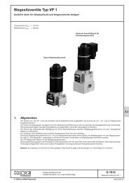
<strong>Pressure</strong> <strong>valves</strong> <strong>type</strong> <strong>MV</strong>.., D<strong>MV</strong>.. <strong>and</strong> <strong>SV</strong>..<br />
<strong>Pressure</strong> limiting <strong>valves</strong>, differential pressure regulators<br />
<strong>Pressure</strong> pmax Flow Qmax Type <strong>MV</strong> <strong>and</strong> <strong>MV</strong>S<br />
<strong>MV</strong>CS<br />
1. General<br />
= 700 bar<br />
= 160 lpm<br />
© 1977 by HAWE Hydraulik<br />
Type <strong>MV</strong>E<br />
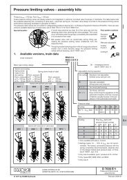
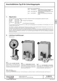
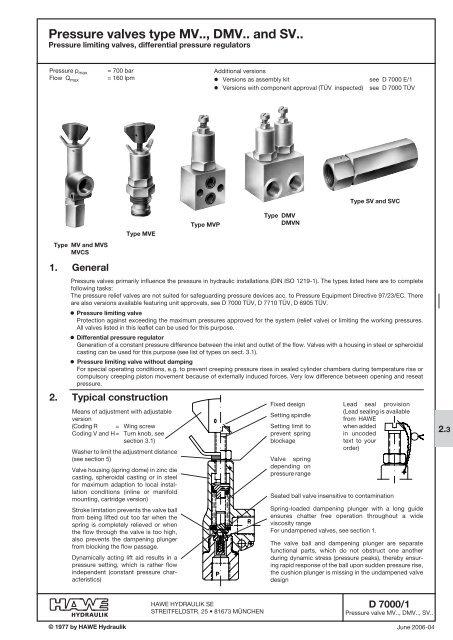
2. Typical construction<br />
Type <strong>MV</strong>P<br />
HAWE HyDrAulik SE<br />
STREITFELDSTR. 25 • 81673 MÜNCHEN<br />
Type D<strong>MV</strong><br />
D<strong>MV</strong>N<br />
Type <strong>SV</strong> <strong>and</strong> <strong>SV</strong>C<br />
<strong>Pressure</strong> <strong>valves</strong> primarily influence the pressure in hydraulic installations (DIN ISO 1219-1). The <strong>type</strong>s listed here are to complete<br />
following tasks:<br />
The pressure relief <strong>valves</strong> are not suited for safeguarding pressure devices acc. to <strong>Pressure</strong> Equipment Directive 97/23/EC. There<br />
are also versions available featuring unit approvals, see D 7000 TÜV, D 7710 TÜV, D 6905 TÜV.<br />
o <strong>Pressure</strong> limiting valve<br />
Protection against exceeding the maximum pressures approved for the system (relief valve) or limiting the working pressures.<br />
All <strong>valves</strong> listed in this leaflet can be used for this purpose.<br />
o Differential pressure regulator<br />
Generation of a constant pressure difference between the inlet <strong>and</strong> outlet of the flow. Valves with a housing in steel or spheroidal<br />
casting can be used for this purpose (see list of <strong>type</strong>s on sect. 3.1).<br />
o <strong>Pressure</strong> limiting valve without damping<br />
For special operating conditions, e.g. to prevent creeping pressure rises in sealed cylinder chambers during temperature rise or<br />
compulsory creeping piston movement because of externally induced forces. Very low difference between opening <strong>and</strong> reseat<br />
pressure.<br />
Means of adjustment with adjustable<br />
version<br />
(Coding R = Wing screw<br />
Coding V <strong>and</strong> H = Turn knob, see<br />
section 3.1)<br />
Washer to limit the adjustment distance<br />
(see section 5)<br />
Valve housing (spring dome) in zinc die<br />
casting, spheroidal casting or in steel<br />
for maximum adaption to local installation<br />
conditions (inline or manifold<br />
mounting, cartridge version)<br />
Stroke limitation prevents the valve ball<br />
from being Iifted out too far when the<br />
spring is completely relieved or when<br />
the flow through the valve is too high,<br />
also prevents the dampening plunger<br />
from blocking the flow passage.<br />
Dynamically acting lift aid results in a<br />
pressure setting, which is rather flow<br />
independent (constant pressure characteristics)<br />
Additional versions<br />
o Versions as assembly kit see D 7000 E/1<br />
o Versions with component approval (TÜV inspected) see D 7000 TÜV<br />
Fixed design<br />
Setting spindle<br />
Setting limit to<br />
prevent spring<br />
blockage<br />
Valve spring<br />
depending on<br />
pressure range<br />
lead seal provision<br />
(Lead sealing is available<br />
from HAWE<br />
when added<br />
in uncoded<br />
text to your<br />
order)<br />
Seated ball valve insensitive to contamination<br />
Spring-loaded dampening plunger with a long guide<br />
ensures chatter free operation throughout a wide<br />
viscosity range<br />
For undampened <strong>valves</strong>, see section 1.<br />
The valve ball <strong>and</strong> dampening plunger are separate<br />
functional parts, which do not obstruct one another<br />
during dynamic stress (pressure peaks), thereby ensuring<br />
rapid response of the ball upon sudden pressure rise,<br />
the cushion plunger is missing in the undampened valve<br />
design<br />
D 7000/1<br />
<strong>Pressure</strong> valve <strong>MV</strong>.., D<strong>MV</strong>.., <strong>SV</strong>..<br />
June 2006-04<br />
2.3
D 7000/1 page 2<br />
3. Types available<br />
3.1 Type code <strong>and</strong> main data<br />
<strong>Pressure</strong> limiting<br />
valve<br />
<strong>Pressure</strong> limiting valve <strong>and</strong> sequence <strong>valves</strong><br />
<strong>Pressure</strong> limiting valve (as shock valve),<br />
pipe mounting<br />
<strong>Pressure</strong> limiting valve with free<br />
return r d P via a by-pass check<br />
valve<br />
Order examples:<br />
Table 1: Basic <strong>type</strong> <strong>and</strong> Size<br />
Brief description<br />
Corner valve for pipe<br />
mounting<br />
(tapped ports P <strong>and</strong> R)<br />
Corner valve for pipe<br />
mounting<br />
(tapped ports P <strong>and</strong> R)<br />
Screw-in valve<br />
(for manifold mounting)<br />
Valve for<br />
(manifold mounting)<br />
For inline installation in a<br />
pipe system<br />
(tapped hole at P <strong>and</strong> R)<br />
Double valve for<br />
hydraulic motor<br />
(tapped hole at P <strong>and</strong> R)<br />
Double valve with suction<br />
valve for cylinders,<br />
(tapped hole at A, B, R)<br />
Single valve with thru-holes<br />
(tapped hole at P <strong>and</strong> R)<br />
Corner valve, pipe<br />
mounting<br />
For inline installation<br />
in a pipe<br />
system<br />
Tapped hole at<br />
P <strong>and</strong> r<br />
Thread journal<br />
at P, tapped<br />
hole at r<br />
Tapped hole at<br />
P <strong>and</strong> r<br />
Thread journal<br />
at P, tapped<br />
hole at r<br />
Connection size <strong>and</strong><br />
thread<br />
Basic <strong>type</strong><br />
Size<br />
41<br />
42<br />
<strong>MV</strong> 52<br />
5) 53<br />
63<br />
64<br />
41<br />
42<br />
52<br />
<strong>MV</strong>S 53<br />
8) 63<br />
64<br />
84<br />
85<br />
4<br />
<strong>MV</strong>E 5<br />
10) 6<br />
8<br />
4<br />
<strong>MV</strong>P 5<br />
10)<br />
6<br />
8<br />
42<br />
<strong>SV</strong> 1) 53<br />
64<br />
85<br />
41<br />
42<br />
52<br />
D<strong>MV</strong> 53<br />
1) 63<br />
64<br />
84<br />
85<br />
42<br />
D<strong>MV</strong>N 53<br />
64<br />
3)<br />
1) 3) 5) 6)<br />
<strong>MV</strong>T<br />
1) 3) 5)<br />
<strong>MV</strong>CS<br />
3) 5)<br />
<strong>SV</strong>C<br />
1) 3) 5)<br />
63<br />
46<br />
56<br />
66<br />
47<br />
58<br />
69<br />
46<br />
56<br />
66<br />
47<br />
58<br />
69<br />
ISO 228/1<br />
(BSPP)<br />
G 3/8<br />
G 1/2<br />
G 3/4<br />
G 1<br />
G 1/4<br />
G 3/8<br />
G 3/8<br />
G 1/2<br />
G 1/2<br />
G 3/4<br />
G 3/4<br />
G 1<br />
G 3/8<br />
G 1/2<br />
G 3/4<br />
G 1/2<br />
G 3/8<br />
G 1/2<br />
G 3/4<br />
G 3/8 (A)<br />
G 1/2 (A)<br />
G 3/4 (A)<br />
G 3/8<br />
G 1/2<br />
G 3/4<br />
G 3/8 (A)<br />
G 1/2 (A)<br />
G 3/4 (A)<br />
Spring dome<br />
material<br />
Port pressure<br />
rating<br />
G 1/4<br />
Zinc die casting<br />
G 3/8<br />
G 3/8<br />
Perm. pressure<br />
P = 700 bar<br />
G 1/2 R = 20 bar<br />
G 1/2<br />
G 3/4<br />
see sect. 3.2<br />
G 1/4 Spheroidal<br />
G 3/8 casting<br />
G 3/8 Perm. pressure<br />
G 1/2 P = 700 bar<br />
G 1/2<br />
G 3/4<br />
R = 500 bar<br />
see sect. 3.2<br />
G 3/4 Steel:<br />
Perm. pressure<br />
G 1<br />
Stepped<br />
bore, see<br />
P <strong>and</strong> R = 400 bar<br />
dimension. Steel:<br />
drawing<br />
Perm. pressure<br />
P = 700 (400) bar<br />
Manifold,<br />
see dimensional<br />
drawing<br />
R = 350 bar<br />
Steel:<br />
Perm. pressure<br />
P = 700 (400) bar<br />
R = 500 (400) bar<br />
Steel:<br />
Perm. pressure<br />
P <strong>and</strong> r<br />
= 350 bar<br />
Steel: Perm.<br />
pressure<br />
A, B = 350 bar<br />
R = 20 bar<br />
Steel: Perm.<br />
pressure P <strong>and</strong><br />
R = 315 bar<br />
Spheroidal<br />
casting<br />
Perm. pressure<br />
P <strong>and</strong> r<br />
= 500 bar<br />
Steel:<br />
Perm. pressure<br />
P <strong>and</strong> r<br />
= 500 bar<br />
<strong>MV</strong>P 4 A - 650<br />
<strong>MV</strong> 53 B R X<br />
D<strong>MV</strong> 4 B/C - 300/200<br />
X = Undampened version acc. to sect. 1<br />
Without St<strong>and</strong>ard, tool adjustable<br />
coding<br />
R Manually adjustable<br />
(Wing screw+wing nut)<br />
V 5) 8) Turn knob (self-locking)<br />
Turn knob lockable<br />
H 5) 10) keys conforming the regulations<br />
of the automotive industry; One<br />
key is scope of delivery (usually<br />
anyway in the possession of the<br />
authorized work staff)<br />
Table 2: <strong>Pressure</strong> range <strong>and</strong> flow<br />
Attention: The pressure will be set acc. to the table<br />
below, if not ordered otherwise<br />
<strong>Pressure</strong> range A 3) B C E F<br />
(0) 4) ...<br />
... p max<br />
(bar)<br />
<strong>Pressure</strong> setting from<br />
HAWE (bar) 2)<br />
Corresponding<br />
flow<br />
Q max (lpm)<br />
<strong>MV</strong>..<br />
D<strong>MV</strong>..<br />
<strong>MV</strong>CS..<br />
<strong>SV</strong>C..<br />
Table 3: Adjustment (during operation)<br />
Size<br />
4, 5, 6<br />
Size 8<br />
Size 4<br />
Size 5<br />
Size 6<br />
Size 8<br />
Desired pressure setting<br />
(bar) (without specification,<br />
see table 2)<br />
700<br />
500<br />
315<br />
160<br />
80<br />
--- 400<br />
450<br />
9) 315 160 ---<br />
400 315 160 80<br />
12<br />
20<br />
40<br />
--<br />
<strong>MV</strong>S.., <strong>MV</strong>E..,<br />
<strong>MV</strong>P.., <strong>SV</strong>..<br />
D<strong>MV</strong>N..<br />
<strong>MV</strong>T..<br />
20<br />
40<br />
75<br />
160<br />
Symbols<br />
Illustration of the st<strong>and</strong>ard version (tool adjustable)<br />
Additional adjustability:<br />
Coding<br />
Coding H<br />
r <strong>and</strong> V<br />
1) Tool adjustable version only<br />
2) When not specified in the order<br />
3) <strong>Pressure</strong> range coding A not avail. for <strong>type</strong> D<strong>MV</strong>, DM-<br />
VN, <strong>MV</strong>T, <strong>MV</strong>CS, <strong>and</strong> <strong>SV</strong>C<br />
4) A setting below 0.1 ... 0.15 p max is not effective. The<br />
min. pressure that can be achieved, when the spring<br />
is completely decommpressed depends on the valve<br />
related back pressure <strong>and</strong> the flow (sect. 3.2)<br />
5) Not available as size 8<br />
6) Suction <strong>valves</strong> serve for the volume compensation,<br />
preventing the formation of a vacuum within hydraulic<br />
cylinders<br />
8) Coding V not available for <strong>type</strong> <strong>MV</strong>S 4<br />
9) <strong>Pressure</strong> range B not available for <strong>type</strong> <strong>SV</strong> 85<br />
10) Coding H not available for <strong>type</strong> <strong>MV</strong>E 4 <strong>and</strong> <strong>MV</strong>P 4
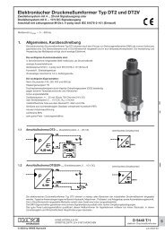
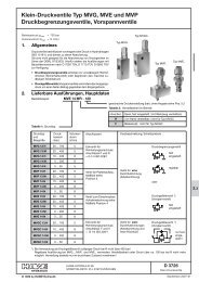
3.2 Additional data<br />
Back pressure |p (bar)<br />
Back pressure |p (bar)<br />
Size 4<br />
Example: <strong>MV</strong> 42C<br />
Flow Q (lpm)<br />
Size 5<br />
Example: <strong>MV</strong> 53C<br />
Size 6<br />
Example: <strong>MV</strong> 64C<br />
Flow Q (lpm) Flow Q (lpm)<br />
Back pressure |p (bar)<br />
D 7000/1 page 3<br />
Nomenclature <strong>and</strong> design <strong>Pressure</strong> valve controlled directly, ball seated design<br />
intended application Zinc die-casting: St<strong>and</strong>ard model for normal production conditions<br />
Spheroidal casting: For rough operation conditions; where mechanical shocks or vibrations<br />
cannot be avoided (automative engineering).<br />
Also when there are pressure surges in the return pipe.<br />
Mounting <strong>and</strong> installet<br />
position<br />
Dep. on <strong>type</strong>, either freely suspended in the pipe work, secured via a thru-hole or screw-in or manifold<br />
mounting; arbitrary installation position<br />
Line connection Steel or spheroidal cast parts zinc galvanized; Spring domes made of zinc pressure die-casting are<br />
untreated<br />
Flow direction P d R, with <strong>SV</strong>C <strong>and</strong> <strong>MV</strong>CS free return flow R d P (Attention: Observe Qmax sect. 3.1, table 2)<br />
Mass (weight) approx. kg Size <strong>MV</strong> <strong>MV</strong>S <strong>MV</strong>E <strong>MV</strong>P <strong>SV</strong> D<strong>MV</strong> D<strong>MV</strong>N <strong>MV</strong>T <strong>MV</strong>CS <strong>SV</strong>C<br />
4 0.2 0.2 0.2 0.3 0.2 0.7 0.8 --- 0.3 0.3<br />
5 0.3 0.3 0.3 0.5 0.3 1.3 1.5 --- 0.4 0.4<br />
6 0.5 0.5 0.4 0.8 0.7 1.8 2.4 1.3 0.7 0.9<br />
8 --- 2.0 1.0 1.6 0.9 4.5 --- --- --- ---<br />
<strong>Pressure</strong> fluid Hydraulic oil conforming DIN 51524 part 1 to 3: ISO VG 10 to 68 conforming DIN 51519.<br />
Viscosity limits: min. approx. 4, max. approx. 1500 mm 2/s, opt. operation approx. 10... 500 mm 2/s.<br />
Also suitable for biological degradable pressure fluids <strong>type</strong>s HEPG (Polyalkylenglycol) <strong>and</strong> HEES<br />
(Synth. Ester) at service temperatures up to approx. +70 °C.<br />
Temperature Ambient: approx. -40 ... +80 °C<br />
Fluid: -25 ... +80°C; Note the viscosity range !<br />
Permissible temperature during start: -40°C (Note start-viscosity!), as long as the service temperature<br />
is at least 20K higher for the following operation. Biological degradable pressure fluids:<br />
Note manufacturer‘s specifications. By consideration of the compatibility with seal material not<br />
over +70 °C.<br />
|p-Q-characteristics Characteristic curve shown with example <strong>MV</strong>..C (basic tendency, there are certain differences<br />
depending on the pressure range <strong>and</strong> the housing shape of the various basic <strong>type</strong>s)<br />
An increased return back pressure will transform the curves into positive |p-figures.<br />
Flow direction r ® P<br />
with <strong>type</strong> <strong>MV</strong>C.. <strong>and</strong> <strong>SV</strong>C..<br />
Size 4<br />
Size 5<br />
Flow Q (lpm)<br />
Oil viscosity during testing 50 mm 2/s<br />
1)<br />
Size 6<br />
1) Design related characteristic back pressure with spring relieved (static pressure value 0 bar).<br />
<strong>Pressure</strong> below this limit line cannot be achieved, see also footnote 4), sect. 3.1<br />
2) Figures in brackets apply to <strong>type</strong> <strong>SV</strong> <strong>and</strong> <strong>SV</strong>C<br />
Size 8<br />
Example: <strong>MV</strong> 85C<br />
Flow Q (lpm)<br />
<strong>Pressure</strong> variations (apply to all <strong>valves</strong> acc. to sect. 3.1). Rough guide line figures<br />
(valve idling) per one turn of the set screw.<br />
<strong>Pressure</strong> range<br />
(bar)<br />
A 0 ... 700<br />
B 0 ... 500 (400)<br />
C 0 ... 315<br />
E 0 ... 160<br />
F 0 ... 80<br />
1) 1) 1)<br />
Size 4<br />
4.5 / 195<br />
(4.3 / 220)<br />
6.3 / 100<br />
(6.1 / 110)<br />
7.1 / 55<br />
(6.5 / 65)<br />
10.5 / 19<br />
(8 / 27)<br />
10.5 / 9,5<br />
(7.2 / 15)<br />
Travel fmax (mm) / |p (bar) per one turn<br />
Size 5 Size 6 Size 8<br />
2)<br />
8.4 / 105<br />
(9.1 / 140)<br />
9.7 / 65<br />
(10 / 90)<br />
7.7 / 51<br />
(7.2 / 80)<br />
12 / 17<br />
(11.2 / 26)<br />
11.5 / 9<br />
(7.3 / 20)<br />
7.4 / 120<br />
(7 / 180)<br />
7.9 / 80<br />
(7 / 130)<br />
10.2 / 35<br />
(9.3 / 62)<br />
11.5 / 17.5<br />
(10 / 29)<br />
12.5 / 8<br />
(9.7 / 15)<br />
---<br />
9 / 68<br />
13 / 37<br />
(12.8 / 57)<br />
12.5 / 20<br />
(12.4 / 30)<br />
---<br />
Attention: Any pressure re-adjustment should be monitored with a pressure<br />
gauge! For adjustment instruction, see section 5
D 7000/1 page 4<br />
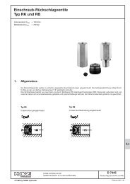
4. Dimensions of units<br />
Provision<br />
for lead<br />
seal<br />
Type <strong>MV</strong> 4(5, 6) <strong>and</strong> <strong>MV</strong>S 4(5, 6)<br />
Means of adjustment coding R<br />
Size<br />
4<br />
5<br />
6<br />
a<br />
15<br />
18<br />
20<br />
Tool adjustable<br />
a1<br />
24<br />
30<br />
35<br />
b<br />
24<br />
29<br />
36<br />
d<br />
5.3<br />
6.4<br />
6.4<br />
For port size, see section 3.1<br />
h<br />
28<br />
31<br />
31<br />
Means of adjustment coding V<br />
Means of adjustment coding H<br />
h1<br />
40<br />
42<br />
44<br />
h2<br />
46<br />
49<br />
62<br />
h3<br />
61<br />
66<br />
82<br />
h4<br />
86<br />
95<br />
117<br />
Type <strong>MV</strong>CS 4(5, 6) Type <strong>MV</strong>S 8<br />
Type <strong>MV</strong>E 4(5, 6, 8) Type <strong>MV</strong>P 4(5, 6, 8)<br />
Size<br />
a/f<br />
4<br />
5<br />
6<br />
8<br />
h7<br />
48<br />
53.5<br />
65.5<br />
90<br />
a/f<br />
a/f 13<br />
a/f 1<br />
h8<br />
26<br />
27<br />
32<br />
40<br />
1)<br />
D<br />
18H8 25H8 25H8 36H8 e7<br />
12<br />
11.5<br />
14<br />
19<br />
d1<br />
6<br />
9<br />
12<br />
16<br />
All dimensions are in mm, subject to change without notice!<br />
t<br />
12<br />
9<br />
10<br />
12<br />
t1<br />
15<br />
16<br />
19<br />
27<br />
Size<br />
4<br />
5<br />
6<br />
8<br />
Size<br />
4<br />
5<br />
6<br />
8<br />
a/f<br />
22<br />
27<br />
30<br />
41<br />
a/f 10<br />
h5<br />
72<br />
82<br />
100<br />
<strong>MV</strong>CS..6<br />
Tapped<br />
holes<br />
shap X<br />
h6<br />
85.5<br />
99.5<br />
120<br />
h14<br />
13<br />
15<br />
17<br />
1) at pressure below<br />
315 bar there is also a<br />
rougher surface<br />
(r e = 1.6; R t = 16)<br />
permissible<br />
Sealing ring<br />
DIN 7603...<br />
A 22x27x1.5 (St)<br />
A 28x34x2 (St)<br />
A 30x36x2 (St)<br />
A 40x49x2 (St)<br />
Thread<br />
G <strong>and</strong> G1<br />
M 22x1.5<br />
M 28x1.5<br />
M 30x1.5<br />
M 40x1.5<br />
a/f1<br />
27<br />
32<br />
36<br />
46<br />
h15<br />
58<br />
58<br />
64<br />
<strong>MV</strong>CS..7(8,9)<br />
Tapped<br />
journal<br />
shape B<br />
similar to DIN 3852 page 2<br />
Torque for<br />
steel (Nm)<br />
65<br />
120<br />
160<br />
300<br />
b1<br />
28<br />
32<br />
35<br />
50<br />
h16<br />
41<br />
41<br />
56<br />
c<br />
7<br />
8<br />
10<br />
15<br />
c1<br />
8<br />
8<br />
10<br />
12<br />
a/f<br />
22<br />
27<br />
30<br />
Mounting hole #3, 4 deep<br />
(for centering pin)<br />
Sealing of ports P <strong>and</strong> r:<br />
Size 4 5 6 8<br />
d1<br />
6<br />
9<br />
12<br />
16<br />
e<br />
20<br />
21<br />
26<br />
30<br />
e1<br />
11<br />
13.5<br />
17<br />
20<br />
e2<br />
7<br />
9<br />
11<br />
13<br />
a/f 17<br />
Thruhole<br />
a/f 41<br />
O-ring 8x2 10x2 13.95x2.62 18.76x2.62<br />
NBR 90 Sh<br />
g h9 l<br />
M 8 39 35<br />
M 8 42 40<br />
M 10 51.5 50<br />
M 12 75 60
Type D<strong>MV</strong> 4(5, 6, 8)<br />
Size<br />
4<br />
5<br />
6<br />
8<br />
b2<br />
40<br />
50<br />
60<br />
80<br />
e3<br />
8<br />
10<br />
10<br />
10<br />
e4<br />
24<br />
30<br />
40<br />
60<br />
e5<br />
14<br />
18<br />
21<br />
27<br />
For port size, see section 3.1<br />
e6<br />
12<br />
15<br />
18<br />
25<br />
f f1 g1 h9<br />
16 24 M 8, 10 deep 39<br />
19 31 M 8, 10 deep 42<br />
23 37 M 10, 12 deep 51.5<br />
30.5 49.5 M 10, 12 deep 75<br />
Type <strong>SV</strong> 4(5, 6, 8)<br />
Type <strong>SV</strong>C 4(5, 6)<br />
Type D<strong>MV</strong>N 42(53, 64) Type <strong>MV</strong>T 63<br />
For port size, see section 3.1<br />
For missing dimensions,<br />
see page 4!<br />
For missing<br />
dimensions,<br />
see page 4!<br />
h10<br />
40<br />
50<br />
60<br />
80<br />
Size b2 e3 e4 e5 e6 e8 e9 g1 h9 h10 i l1<br />
4 40 5 30 21.5 11 20.5 29 M6, 10 deep 39 40 9 65<br />
5 50 7.5 35 27 14 26.5 36 M8, 12 deep 42 50 9 82<br />
6 60 9 42 32 16.5 32 44 M10, 12 deep 51.5 60 5 97<br />
l1<br />
52<br />
65<br />
75<br />
96<br />
<strong>SV</strong>C..6: Tapped holes 1) form X<br />
<strong>SV</strong>C..7(8,9): Threaded stem 1) form B<br />
Size<br />
4<br />
5<br />
6<br />
8<br />
a/f<br />
a/f<br />
h11<br />
87<br />
104<br />
129<br />
157<br />
h12<br />
73<br />
90<br />
112<br />
---<br />
For port size, see section 3.1<br />
1) similar to DIN 3852 page 2<br />
Provision for<br />
lead seal<br />
For port size, see section 3.1<br />
h13<br />
87<br />
108<br />
132<br />
---<br />
D 7000/1 page 5<br />
h14<br />
13<br />
15<br />
17<br />
---<br />
a/f<br />
22<br />
27<br />
32<br />
41<br />
a/f 13<br />
a/f<br />
Size b2 e e1 e3 e4 e6 e8 h15 h16 h17 a/f<br />
6 35 32 50 7 36 14 50 52 70 27 30
D 7000/1 page 6<br />
5. Adjustment instruction<br />
The <strong>valves</strong> are delivered with proper setting from HAWE, when specified in your order (e.g. <strong>MV</strong> 53C - 250 bar). Washers prevent<br />
unauthorized increasing of the set pressure at adjustable <strong>valves</strong>. The pressure will be set acc. to they table 2 in sect. 3.1, if not<br />
ordered otherwise. Any pressure adjustment should be monitored by a pressure gauge <strong>and</strong> while the pump is running.<br />
o Reduction of the setting<br />
1. <strong>Pressure</strong> gauge connected to the pressure pipe (pressure gallery)<br />
2. Type <strong>MV</strong>... <strong>and</strong> D<strong>MV</strong>(N): Loosen the lock nut (remove lead seal if necessary)<br />
Type <strong>SV</strong>(C): Loosen grub screw<br />
3. Turn the adjustment device counter clockwise (monitored by a pressure gauge)<br />
4. Tighten the lock nut / grub screw after finished procedure. Renew the lead seal if required<br />
o Raising of the setting<br />
Observe the p max figures stated in section 3.1 !<br />
In principle proceed as above. <strong>Pressure</strong> increase when turned clockwise. Washers usually prevent unauthorized increasing<br />
of the pressure with manually adjustable versions. It is therefore necessary to remove enough of them (after driving the rollpin<br />
out of the winged h<strong>and</strong>le) before the increased pressure can be set. Again any pressure adjustment should be monitored by a<br />
pressure gauge. After finishing the setting procedure sufficient washers, the winged locknut, the winged h<strong>and</strong>le <strong>and</strong> the rollpin<br />
must be reinstalled.<br />
Tool adjustable<br />
Set screw<br />
Jam nut<br />
Grub screw<br />
Threaded adjustment<br />
device<br />
<strong>Pressure</strong> pipe <strong>Pressure</strong> pipe<br />
Manually adjustable,<br />
adjustment device<br />
coding r<br />
H<strong>and</strong>le<br />
rollpin<br />
Size<br />
4, 5 <strong>and</strong> 6<br />
5585 023 a<br />
#12x#8.2x0.3<br />
5585 023 b<br />
#12x#8.2x0.5<br />
5585 023 c<br />
#12x#8.2x1.5<br />
5585 023 d<br />
#12x#8.2x0.75<br />
5585 023 e<br />
#12x#8.2x1<br />
5585 023 f<br />
#12x#8.2x2<br />
5585 023 g<br />
#12x#8.2x3<br />
5585 023 h<br />
#12x#8.2x4<br />
Washer<br />
Size 8<br />
7187 023 a<br />
#10x#15x0.5<br />
7187 023 b<br />
#10x#15x1<br />
7187 023 c<br />
#10x#15x2<br />
7187 023 d<br />
#10x#15x5<br />
Means of adjustment<br />
coding V <strong>and</strong> H<br />
Note: The pressure reading on the dial during adjustment, while the pump is running is always corresponding to this flow. Flow<br />
deviations will cause a slightly differing response pressure, depending on the design related back pressure of the valve<br />
housing (see sect. 3.2). Please add to your order coding in uncoded text „set at start of response“ when required e.g. for a<br />
pressure limiting valve intended for a h<strong>and</strong> pump Q , 0 lpm.