Pressure valves type MV.., DMV.. and SV.. - EUROFLUID
Pressure valves type MV.., DMV.. and SV.. - EUROFLUID
Pressure valves type MV.., DMV.. and SV.. - EUROFLUID

Create successful ePaper yourself
Turn your PDF publications into a flip-book with our unique Google optimized e-Paper software.
D 7000/1 page 6<br />
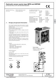
5. Adjustment instruction<br />
The <strong>valves</strong> are delivered with proper setting from HAWE, when specified in your order (e.g. <strong>MV</strong> 53C - 250 bar). Washers prevent<br />
unauthorized increasing of the set pressure at adjustable <strong>valves</strong>. The pressure will be set acc. to they table 2 in sect. 3.1, if not<br />
ordered otherwise. Any pressure adjustment should be monitored by a pressure gauge <strong>and</strong> while the pump is running.<br />
o Reduction of the setting<br />
1. <strong>Pressure</strong> gauge connected to the pressure pipe (pressure gallery)<br />
2. Type <strong>MV</strong>... <strong>and</strong> D<strong>MV</strong>(N): Loosen the lock nut (remove lead seal if necessary)<br />
Type <strong>SV</strong>(C): Loosen grub screw<br />
3. Turn the adjustment device counter clockwise (monitored by a pressure gauge)<br />
4. Tighten the lock nut / grub screw after finished procedure. Renew the lead seal if required<br />
o Raising of the setting<br />
Observe the p max figures stated in section 3.1 !<br />
In principle proceed as above. <strong>Pressure</strong> increase when turned clockwise. Washers usually prevent unauthorized increasing<br />
of the pressure with manually adjustable versions. It is therefore necessary to remove enough of them (after driving the rollpin<br />
out of the winged h<strong>and</strong>le) before the increased pressure can be set. Again any pressure adjustment should be monitored by a<br />
pressure gauge. After finishing the setting procedure sufficient washers, the winged locknut, the winged h<strong>and</strong>le <strong>and</strong> the rollpin<br />
must be reinstalled.<br />
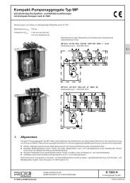
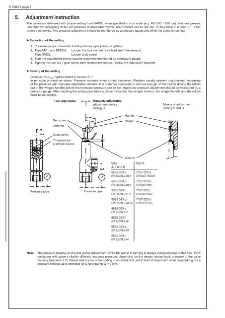
Tool adjustable<br />
Set screw<br />
Jam nut<br />
Grub screw<br />
Threaded adjustment<br />
device<br />
<strong>Pressure</strong> pipe <strong>Pressure</strong> pipe<br />
Manually adjustable,<br />
adjustment device<br />
coding r<br />
H<strong>and</strong>le<br />
rollpin<br />
Size<br />
4, 5 <strong>and</strong> 6<br />
5585 023 a<br />
#12x#8.2x0.3<br />
5585 023 b<br />
#12x#8.2x0.5<br />
5585 023 c<br />
#12x#8.2x1.5<br />
5585 023 d<br />
#12x#8.2x0.75<br />
5585 023 e<br />
#12x#8.2x1<br />
5585 023 f<br />
#12x#8.2x2<br />
5585 023 g<br />
#12x#8.2x3<br />
5585 023 h<br />
#12x#8.2x4<br />
Washer<br />
Size 8<br />
7187 023 a<br />
#10x#15x0.5<br />
7187 023 b<br />
#10x#15x1<br />
7187 023 c<br />
#10x#15x2<br />
7187 023 d<br />
#10x#15x5<br />
Means of adjustment<br />
coding V <strong>and</strong> H<br />
Note: The pressure reading on the dial during adjustment, while the pump is running is always corresponding to this flow. Flow<br />
deviations will cause a slightly differing response pressure, depending on the design related back pressure of the valve<br />
housing (see sect. 3.2). Please add to your order coding in uncoded text „set at start of response“ when required e.g. for a<br />
pressure limiting valve intended for a h<strong>and</strong> pump Q , 0 lpm.