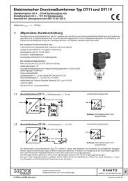
Pressure valves type MV.., DMV.. and SV.. - EUROFLUID
Pressure valves type MV.., DMV.. and SV.. - EUROFLUID
Pressure valves type MV.., DMV.. and SV.. - EUROFLUID

Create successful ePaper yourself
Turn your PDF publications into a flip-book with our unique Google optimized e-Paper software.
3.2 Additional data<br />
Back pressure |p (bar)<br />
Back pressure |p (bar)<br />
Size 4<br />
Example: <strong>MV</strong> 42C<br />
Flow Q (lpm)<br />
Size 5<br />
Example: <strong>MV</strong> 53C<br />
Size 6<br />
Example: <strong>MV</strong> 64C<br />
Flow Q (lpm) Flow Q (lpm)<br />
Back pressure |p (bar)<br />
D 7000/1 page 3<br />
Nomenclature <strong>and</strong> design <strong>Pressure</strong> valve controlled directly, ball seated design<br />
intended application Zinc die-casting: St<strong>and</strong>ard model for normal production conditions<br />
Spheroidal casting: For rough operation conditions; where mechanical shocks or vibrations<br />
cannot be avoided (automative engineering).<br />
Also when there are pressure surges in the return pipe.<br />
Mounting <strong>and</strong> installet<br />
position<br />
Dep. on <strong>type</strong>, either freely suspended in the pipe work, secured via a thru-hole or screw-in or manifold<br />
mounting; arbitrary installation position<br />
Line connection Steel or spheroidal cast parts zinc galvanized; Spring domes made of zinc pressure die-casting are<br />
untreated<br />
Flow direction P d R, with <strong>SV</strong>C <strong>and</strong> <strong>MV</strong>CS free return flow R d P (Attention: Observe Qmax sect. 3.1, table 2)<br />
Mass (weight) approx. kg Size <strong>MV</strong> <strong>MV</strong>S <strong>MV</strong>E <strong>MV</strong>P <strong>SV</strong> D<strong>MV</strong> D<strong>MV</strong>N <strong>MV</strong>T <strong>MV</strong>CS <strong>SV</strong>C<br />
4 0.2 0.2 0.2 0.3 0.2 0.7 0.8 --- 0.3 0.3<br />
5 0.3 0.3 0.3 0.5 0.3 1.3 1.5 --- 0.4 0.4<br />
6 0.5 0.5 0.4 0.8 0.7 1.8 2.4 1.3 0.7 0.9<br />
8 --- 2.0 1.0 1.6 0.9 4.5 --- --- --- ---<br />
<strong>Pressure</strong> fluid Hydraulic oil conforming DIN 51524 part 1 to 3: ISO VG 10 to 68 conforming DIN 51519.<br />
Viscosity limits: min. approx. 4, max. approx. 1500 mm 2/s, opt. operation approx. 10... 500 mm 2/s.<br />
Also suitable for biological degradable pressure fluids <strong>type</strong>s HEPG (Polyalkylenglycol) <strong>and</strong> HEES<br />
(Synth. Ester) at service temperatures up to approx. +70 °C.<br />
Temperature Ambient: approx. -40 ... +80 °C<br />
Fluid: -25 ... +80°C; Note the viscosity range !<br />
Permissible temperature during start: -40°C (Note start-viscosity!), as long as the service temperature<br />
is at least 20K higher for the following operation. Biological degradable pressure fluids:<br />
Note manufacturer‘s specifications. By consideration of the compatibility with seal material not<br />
over +70 °C.<br />
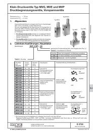
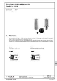
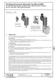
|p-Q-characteristics Characteristic curve shown with example <strong>MV</strong>..C (basic tendency, there are certain differences<br />
depending on the pressure range <strong>and</strong> the housing shape of the various basic <strong>type</strong>s)<br />
An increased return back pressure will transform the curves into positive |p-figures.<br />
Flow direction r ® P<br />
with <strong>type</strong> <strong>MV</strong>C.. <strong>and</strong> <strong>SV</strong>C..<br />
Size 4<br />
Size 5<br />
Flow Q (lpm)<br />
Oil viscosity during testing 50 mm 2/s<br />
1)<br />
Size 6<br />
1) Design related characteristic back pressure with spring relieved (static pressure value 0 bar).<br />
<strong>Pressure</strong> below this limit line cannot be achieved, see also footnote 4), sect. 3.1<br />
2) Figures in brackets apply to <strong>type</strong> <strong>SV</strong> <strong>and</strong> <strong>SV</strong>C<br />
Size 8<br />
Example: <strong>MV</strong> 85C<br />
Flow Q (lpm)<br />
<strong>Pressure</strong> variations (apply to all <strong>valves</strong> acc. to sect. 3.1). Rough guide line figures<br />
(valve idling) per one turn of the set screw.<br />
<strong>Pressure</strong> range<br />
(bar)<br />
A 0 ... 700<br />
B 0 ... 500 (400)<br />
C 0 ... 315<br />
E 0 ... 160<br />
F 0 ... 80<br />
1) 1) 1)<br />
Size 4<br />
4.5 / 195<br />
(4.3 / 220)<br />
6.3 / 100<br />
(6.1 / 110)<br />
7.1 / 55<br />
(6.5 / 65)<br />
10.5 / 19<br />
(8 / 27)<br />
10.5 / 9,5<br />
(7.2 / 15)<br />
Travel fmax (mm) / |p (bar) per one turn<br />
Size 5 Size 6 Size 8<br />
2)<br />
8.4 / 105<br />
(9.1 / 140)<br />
9.7 / 65<br />
(10 / 90)<br />
7.7 / 51<br />
(7.2 / 80)<br />
12 / 17<br />
(11.2 / 26)<br />
11.5 / 9<br />
(7.3 / 20)<br />
7.4 / 120<br />
(7 / 180)<br />
7.9 / 80<br />
(7 / 130)<br />
10.2 / 35<br />
(9.3 / 62)<br />
11.5 / 17.5<br />
(10 / 29)<br />
12.5 / 8<br />
(9.7 / 15)<br />
---<br />
9 / 68<br />
13 / 37<br />
(12.8 / 57)<br />
12.5 / 20<br />
(12.4 / 30)<br />
---<br />
Attention: Any pressure re-adjustment should be monitored with a pressure<br />
gauge! For adjustment instruction, see section 5