Pedestrian Test Protocol - Euro NCAP
Pedestrian Test Protocol - Euro NCAP
Pedestrian Test Protocol - Euro NCAP

Create successful ePaper yourself
Turn your PDF publications into a flip-book with our unique Google optimized e-Paper software.
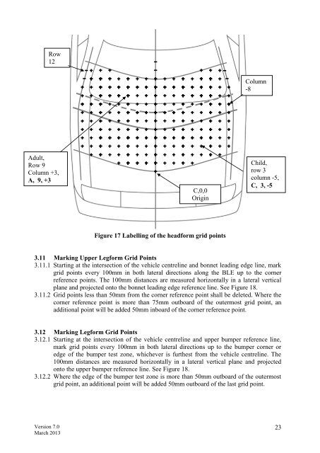
Row<br />
12<br />
Adult,<br />
Row 9<br />
Column +3,<br />
A, 9, +3<br />
Version 7.0<br />
March 2013<br />
C,0,0<br />
Origin<br />
Figure 17 Labelling of the headform grid points<br />
Column<br />
-8<br />
Child,<br />
row 3<br />
column -5,<br />
C, 3, -5<br />
3.11 Marking Upper Legform Grid Points<br />
3.11.1 Starting at the intersection of the vehicle centreline and bonnet leading edge line, mark<br />
grid points every 100mm in both lateral directions along the BLE up to the corner<br />
reference points. The 100mm distances are measured horizontally in a lateral vertical<br />
plane and projected onto the bonnet leading edge reference line. See Figure 18.<br />
3.11.2 Grid points less than 50mm from the corner reference point shall be deleted. Where the<br />
corner reference point is more than 75mm outboard of the outermost grid point, an<br />
additional point will be added 50mm inboard of the corner reference point.<br />
3.12 Marking Legform Grid Points<br />
3.12.1 Starting at the intersection of the vehicle centreline and upper bumper reference line,<br />
mark grid points every 100mm in both lateral directions up to the bumper corner or<br />
edge of the bumper test zone, whichever is furthest from the vehicle centreline. The<br />
100mm distances are measured horizontally in a lateral vertical plane and projected<br />
onto the upper bumper reference line. See Figure 18.<br />
3.12.2 Where the edge of the bumper test zone is more than 50mm outboard of the outermost<br />
grid point, an additional point will be added 50mm outboard of the last grid point.<br />
23