Pedestrian Test Protocol - Euro NCAP
Pedestrian Test Protocol - Euro NCAP
Pedestrian Test Protocol - Euro NCAP

You also want an ePaper? Increase the reach of your titles
YUMPU automatically turns print PDFs into web optimized ePapers that Google loves.
Version 7.0<br />
March 2013<br />
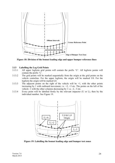
100mm Intervals<br />
Corner Reference Point<br />
Edge of Bumper <strong>Test</strong> Zone<br />
Figure 18: Division of the bonnet leading edge and upper bumper reference lines<br />
3.13 Labelling the Leg Grid Points<br />
3.13.1 All upper legform grid points will contain the prefix ‘U’. All legform points will<br />
contain the prefix ‘L’.<br />
3.13.2 The grid points will be marked sequentially from the origin at the grid points on the<br />
vehicle centreline. For the upper legform, the origin will be marked U0. For the<br />
legform the origin will be marked L0.<br />
3.13.3 The adjacent points on the right of the vehicle will be +1, with the other points<br />
increasing by 1 with outboard movement, i.e. +2, +3 etc. The points on the left of the<br />
vehicle -1 with the other columns decreasing by 1 i.e. -2, -3 etc.<br />
3.13.4 Every point will be labelled firstly by the relevant impactor (U or L), then by the<br />
individual number. See Figure 19.<br />
U,+6<br />
U,+2<br />
U,0 & L,0<br />
Origin<br />
L,-3<br />
Figure 19: Labelling the bonnet leading edge and bumper test zones<br />
24