Numerical modelin of floating prefabricated vertical drains in layered ...
Numerical modelin of floating prefabricated vertical drains in layered ...
Numerical modelin of floating prefabricated vertical drains in layered ...

You also want an ePaper? Increase the reach of your titles
YUMPU automatically turns print PDFs into web optimized ePapers that Google loves.
NUMERICAL MODELING OF FLOATING PREFABRI-<br />
CATED VERTICAL DRAINS IN LAYERED SOIL<br />
IKHYA IKHYA and HELMUT F. SCHWEIGER<br />
about the authors<br />
Ikhya Ikhya<br />
Graz University <strong>of</strong> Technology (TU Graz),<br />
Institute for Soil Mechanics and Foundation Eng<strong>in</strong>eer<strong>in</strong>g,<br />
Computational Geotechnics Group<br />
Rechbauerstrasse 12, 8010 Graz, Austria<br />
e-mail: ikhya@tugraz.at, ikhya@itenas.ac.id<br />
Helmut F. Schweiger<br />
Graz University <strong>of</strong> Technology (TU Graz),<br />
Institute for Soil Mechanics and Foundation Eng<strong>in</strong>eer<strong>in</strong>g,<br />
Computational Geotechnics Group<br />
Rechbauerstrasse 12, 8010 Graz, Austria<br />
e-mail: helmut.schweiger@tugraz.at<br />
Abstract<br />
This paper presents a comparison <strong>of</strong> field measurements<br />
and a numerical model <strong>of</strong> settlements based on the<br />
construction <strong>of</strong> an embankment on s<strong>of</strong>t soil for the Cirebon<br />
Power Plant Project <strong>in</strong> Indonesia, where <strong>prefabricated</strong><br />
<strong>vertical</strong> <strong>dra<strong>in</strong>s</strong> (PVDs) were <strong>in</strong>stalled. In the numerical<br />
model, <strong>float<strong>in</strong>g</strong> PVDs <strong>in</strong> two soil layers for two- and oneway<br />
dra<strong>in</strong>age conditions are exam<strong>in</strong>ed <strong>in</strong> order to determ<strong>in</strong>e<br />
the optimum penetration depth. In this study, good<br />
agreement between the field measurements <strong>of</strong> the settlements<br />
and the numerical prediction could be achieved.<br />
An <strong>in</strong>terest<strong>in</strong>g result <strong>of</strong> this study is that the differences <strong>in</strong><br />
the stiffness and/or the permeability <strong>in</strong> the unimproved<br />
area below the PVD tip have a significant <strong>in</strong>fluence on the<br />
optimum penetration depth (L/H) <strong>in</strong> the two-soil-layer<br />
condition. The numerical study showed that it is possible<br />
to use <strong>float<strong>in</strong>g</strong> PVDs <strong>in</strong> s<strong>in</strong>gle dra<strong>in</strong>age conditions if the<br />
second layer is stiffer and/or more permeable than the first<br />
layer.<br />
Keywords<br />
two soil layers, <strong>float<strong>in</strong>g</strong> <strong>prefabricated</strong> <strong>vertical</strong> dra<strong>in</strong>,<br />
double and s<strong>in</strong>gle dra<strong>in</strong>age, numerical model, s<strong>of</strong>t clay,<br />
consolidation<br />
1 INTRODUCTION<br />
S<strong>of</strong>t soil deposits such as s<strong>of</strong>t clays, organic soils, and<br />
peats are generally characterized by a low shear strength,<br />
a high compressibility, and a low coefficient <strong>of</strong> permeability,<br />
which makes them a difficult soil for eng<strong>in</strong>eer<strong>in</strong>g.<br />
S<strong>of</strong>t soil deposits can be found throughout the world,<br />
<strong>in</strong>clud<strong>in</strong>g many parts <strong>of</strong> Indonesia, which possesses one<br />
<strong>of</strong> the longest coastl<strong>in</strong>es <strong>in</strong> the world, with many <strong>of</strong> them<br />
hav<strong>in</strong>g s<strong>of</strong>t soil deposits. The total area <strong>of</strong> s<strong>of</strong>t soil deposits<br />
<strong>in</strong> Indonesia is around 20 million hectares, i.e., 10%<br />
<strong>of</strong> Indonesia’s total land area, which is mostly located <strong>in</strong><br />
the coastal areas [1]. There are s<strong>of</strong>t clays and peats with<br />
vary<strong>in</strong>g depth, shown as black areas <strong>in</strong> figure 1.<br />
Ground-improvement techniques play an important role<br />
<strong>in</strong> extend<strong>in</strong>g the <strong>in</strong>frastructure across the country <strong>in</strong><br />
difficult soils. Vertical <strong>dra<strong>in</strong>s</strong> comb<strong>in</strong>ed with preload<strong>in</strong>g<br />
have become common practice and are among the most<br />
effective procedures for ground improvement, accelerat<strong>in</strong>g<br />
the consolidation process and decreas<strong>in</strong>g the time to<br />
reach f<strong>in</strong>al settlements. The <strong>in</strong>stallation <strong>of</strong> <strong>vertical</strong> <strong>dra<strong>in</strong>s</strong><br />
reduces the dra<strong>in</strong>age path and speeds up the excess porewater<br />
pressure dissipation generated dur<strong>in</strong>g the application<br />
<strong>of</strong> surcharge loads <strong>in</strong> saturated, f<strong>in</strong>e-gra<strong>in</strong>ed soils,<br />
thereby result<strong>in</strong>g <strong>in</strong> the faster development <strong>of</strong> settlements<br />
and a more rapid ga<strong>in</strong> <strong>of</strong> strength due to consolidation.<br />
It seems that almost all published numerical and analytical<br />
studies <strong>of</strong> soil consolidation with <strong>float<strong>in</strong>g</strong> PVDs considered<br />
a homogeneous soil layer and a two-way dra<strong>in</strong>age<br />
condition [2-11], which means that none <strong>of</strong> those studies<br />
focused on evaluat<strong>in</strong>g the effects <strong>of</strong> <strong>in</strong>homogeneous soil<br />
layer<strong>in</strong>g <strong>in</strong> two- and one-way dra<strong>in</strong>age conditions.<br />
In this study the effects <strong>of</strong> <strong>float<strong>in</strong>g</strong> PVDs <strong>in</strong> two soil<br />
layers for two- and one-way dra<strong>in</strong>age conditions are<br />
numerically <strong>in</strong>vestigated <strong>in</strong> order to determ<strong>in</strong>e the<br />
optimum penetration depth. The results from this study<br />
can be used for similar cases where the sub-soil condition<br />
consists <strong>of</strong> more than one soil layer with similar<br />
mechanical and hydraulical properties.<br />
ACTA GEOTECHNICA SLOVENICA, 2012/2 25.
I. IKHYA & H. F. SCHWEIGER: NUMERICAL MODELING OF FLOATING PREFABRICATED VERTICAL DRAINS IN LAYERED SOIL<br />
2 SITE DESCRIPTION AND<br />
GROUND CONDITION<br />
The Cirebon Power Plant site is located on the north<br />
coastal pla<strong>in</strong> <strong>of</strong> Java, near Kanci Village, which is<br />
approximately 20 kilometres to the south-east <strong>of</strong> Cirebon<br />
city and around 290 kilometres to the east <strong>of</strong> Jakarta<br />
city. The site is bounded by the Java Sea to the north,<br />
the Kanci River to the east, and the Waruduwur River to<br />
the west. The area <strong>of</strong> the s<strong>in</strong>gle-unit 660MW coal-fired<br />
power station covers around 50 hectares. The topography<br />
<strong>of</strong> the plant site comprises a relatively flat and<br />
low-ly<strong>in</strong>g area with an average elevation <strong>of</strong> around +0.5<br />
meters above mean sea level. The coast <strong>of</strong> the Cirebon<br />
area has a tidal range between 0.5 to 1.3 meters [12]. An<br />
overview <strong>of</strong> the s<strong>of</strong>t soil areas <strong>in</strong> Indonesia and the location<br />
<strong>of</strong> the Cirebon Power Plant are shown <strong>in</strong> figure 1.<br />
In order to establish a horizontal platform and to keep<br />
the site above flood level and always dry dur<strong>in</strong>g the life<br />
time <strong>of</strong> the plant, the entire plant site area was reclaimed<br />
to reach a f<strong>in</strong>al elevation <strong>of</strong> +2.50 meters above mean<br />
sea level. The average thickness <strong>of</strong> the land fill is about 4<br />
meters, <strong>in</strong>clud<strong>in</strong>g a 1.0 meter sand blanket, a 2.0 meter<br />
embankment, and 1.0 meter additional surcharge [13, 14].<br />
26. ACTA GEOTECHNICA SLOVENICA, 2012/2<br />
Figure 1. S<strong>of</strong>t soil areas <strong>in</strong> Indonesia and the location <strong>of</strong> the Cirebon Power Plant.<br />
The formation <strong>of</strong> the northern coast <strong>of</strong> Java, some on the<br />
North East Sumatra, and the other coastal areas <strong>of</strong> Indonesia,<br />
are normally Holocene s<strong>of</strong>t clay deposits and quite<br />
similar to parts <strong>of</strong> the coasts <strong>of</strong> S<strong>in</strong>gapore, Malaysia,<br />
Thailand, and <strong>in</strong> the other South East Asia countries [15,<br />
16]. Based on the result <strong>of</strong> the soil <strong>in</strong>vestigation [17, 18,<br />
14], the condition <strong>of</strong> the subsurface soils <strong>in</strong> the site area<br />
can be classified <strong>in</strong>to three dist<strong>in</strong>ct soil layers: on top is a<br />
6 meter very s<strong>of</strong>t clay layer followed by a 6 meter s<strong>of</strong>t-tomedium<br />
clay layer, which is underla<strong>in</strong> by a dense sand or<br />
a silty sand layer as the bear<strong>in</strong>g strata. The ground-water<br />
table is located close to the ground surface.<br />
To speed up the consolidation process <strong>of</strong> the top 12<br />
meters <strong>of</strong> s<strong>of</strong>t clay, PVDs together with 4.0 meters <strong>of</strong><br />
fill<strong>in</strong>g material were <strong>in</strong>stalled, which can be considered<br />
to be a good solution <strong>in</strong> terms <strong>of</strong> cost and time efficiency.<br />
The <strong>dra<strong>in</strong>s</strong> were <strong>in</strong>stalled to a depth <strong>of</strong> 12 meters<br />
until reach<strong>in</strong>g the dense soil layer with a 1.5 meter<br />
centre-to-centre spac<strong>in</strong>g <strong>in</strong> a triangular grid pattern. The<br />
settlement plate and the <strong>dra<strong>in</strong>s</strong> were <strong>in</strong>stalled after the<br />
construction <strong>of</strong> a 1.0 meter sand blanket as the work<strong>in</strong>g<br />
area. A settlement analysis due to the areal fill was<br />
carried out around the centre <strong>of</strong> the fill [13]. The subsoil<br />
conditions, embankment thickness, PVD layout and the<br />
location <strong>of</strong> the settlement plate are shown <strong>in</strong> figure 2.
3 NUMERICAL MODEL<br />
I. IKHYA & H. F. SCHWEIGER: NUMERICAL MODELING OF FLOATING PREFABRICATED VERTICAL DRAINS IN LAYERED SOIL<br />
Figure 2. Subsoil and embankment condition, PVD configuration, and location <strong>of</strong> the settlement plate.<br />
A <strong>Numerical</strong> model us<strong>in</strong>g the commercial f<strong>in</strong>ite-element<br />
s<strong>of</strong>tware PLAXIS 2D 2010 was used to analyse this case<br />
study [19]. Axisymmetric conditions were choosen to<br />
simulate a unit-cell condition with a s<strong>in</strong>gle dra<strong>in</strong> at the<br />
center <strong>of</strong> the fill area. The total number <strong>of</strong> elements<br />
(15-noded triangles) <strong>in</strong> this model is 1343. The soil and<br />
the embankment were modelled us<strong>in</strong>g the Harden<strong>in</strong>g<br />
Soil model, the advanced soil model <strong>in</strong> Plaxis for simu-<br />
lat<strong>in</strong>g both s<strong>of</strong>t and stiff soils [20, 19]. Four different<br />
cases are considered <strong>in</strong> the numerical simulation: without<br />
improvement, with PVD improvement but ignor<strong>in</strong>g<br />
smear effects, with PVD improvement consider<strong>in</strong>g the<br />
effects <strong>of</strong> smear caused by PVD <strong>in</strong>stallation and partial<br />
penetration <strong>of</strong> PVDs. The results from this numerical<br />
model were compared with data measured <strong>in</strong> the field.<br />
Figure 3 shows the geometry <strong>of</strong> the unit cell and the<br />
f<strong>in</strong>ite-element mesh <strong>in</strong> the axisymmetric condition for<br />
both full and <strong>float<strong>in</strong>g</strong> PVDs.<br />
Figure 3. Geometry <strong>of</strong> unit cell and f<strong>in</strong>ite-element mesh for full penetration and <strong>float<strong>in</strong>g</strong> PVD.<br />
ACTA GEOTECHNICA SLOVENICA, 2012/2 27.
I. IKHYA & H. F. SCHWEIGER: NUMERICAL MODELING OF FLOATING PREFABRICATED VERTICAL DRAINS IN LAYERED SOIL<br />
The <strong>dra<strong>in</strong>s</strong> were <strong>in</strong>stalled to a depth <strong>of</strong> 12 and 8.4 meters<br />
(L) for full and partial penetration, respectively, with a<br />
1.5 meter spac<strong>in</strong>g (S) <strong>in</strong> a triangular grid pattern. The<br />
s<strong>of</strong>t clay layer to be improved was 12 meters thick (H).<br />
The equivalent <strong>in</strong>fluence zone diameter (the unit-cell<br />
diameter, d e) is 1.575 meter, calculated based on the<br />
pr<strong>in</strong>ciple <strong>of</strong> equal area (d e=1.05 . S). The equivalent<br />
dra<strong>in</strong> diameter (d w) is 66 mm, calculated based on<br />
the equal dra<strong>in</strong>age perimeter assumption proposed by<br />
Hansbo [21] d w = 2(a . b/π), where a = 100 mm and b =<br />
4 mm are the width and thickness <strong>of</strong> the dra<strong>in</strong>. Chai and<br />
Miura [22] suggested that the equivalent smeared zone<br />
diameter (d s) can be estimated as d s = 3 . d m, where d m =<br />
120 mm is the equivalent mandrel or anchor diameter.<br />
The horizontal and <strong>vertical</strong> soil permeability are assumed<br />
to be the same (k h = k v), which is probably slightly<br />
unrealistic, but as no further <strong>in</strong>formation was available<br />
and the problem is considered to be governed by k h,<br />
with the exception <strong>of</strong> <strong>float<strong>in</strong>g</strong> PVDs, this assumption<br />
has been made. The ratio <strong>of</strong> the horizontal permeability<br />
<strong>in</strong> the undisturbed soil zone to the permeability <strong>in</strong> the<br />
HS Model<br />
Parameters<br />
Dra<strong>in</strong>age<br />
Condition<br />
ref ref<br />
Thickness γunat /γsat E50 = Eeod<br />
28. ACTA GEOTECHNICA SLOVENICA, 2012/2<br />
Table 1. Soil and embankment properties.<br />
ref<br />
Eur smeared zone (k h/k s) is 2 and the well resistance is not<br />
taken <strong>in</strong>to account because the dra<strong>in</strong>-discharge capacity<br />
(q w) is assumed to be large enough. The sand blanket is<br />
free dra<strong>in</strong><strong>in</strong>g and the bottom boundary is set to be open<br />
because a permeable soil layer is below the s<strong>of</strong>t clay layer.<br />
Harden<strong>in</strong>g soil model parameters for the soil and the<br />
embankment used <strong>in</strong> the model are summarized <strong>in</strong> table<br />
1. These parameters are based on the geotechnical report<br />
for this project and it is obvious that the values used for<br />
effective cohesion are rather optimistic for this type <strong>of</strong><br />
soil. However, as the ultimate limit-state conditions are<br />
not considered, it can be argued that this assumption has<br />
no serious consequences for the results discussed <strong>in</strong> this<br />
study and thus the values given <strong>in</strong> the geotechnical report<br />
have been kept. In addition, one would expect the soil to<br />
exhibit creep behaviour, but this would be more relevant<br />
<strong>in</strong> the long-term assessment <strong>of</strong> settlements, which is not<br />
the topic <strong>of</strong> this <strong>in</strong>vestigation, although it is acknowledged<br />
that some creep may occur with<strong>in</strong> the time frame analysed,<br />
but it is argued that due to the <strong>in</strong>stallation <strong>of</strong> the<br />
PVDs consolidation is prevail<strong>in</strong>g. The calculation phases<br />
to simulate the stages <strong>of</strong> construction are shown <strong>in</strong> table 2.<br />
nc<br />
m(power) c'ref φ' U'ur pref K0 m kN/m2 kN/m2 kN/m2 - kN/m2 ° - kN/m3 - - m/s<br />
Soil Layer I Undra<strong>in</strong>ed 6 15/16 1000 3000 0.9 12 24 0.2 100 0.593 0.9 1.9×10⁻⁹ Soil Layer II Undra<strong>in</strong>ed 6 17/18 3000 9000 0.7 1 28 0.2 100 0.530 0.9 5.0×10⁻⁹ Embankment Dra<strong>in</strong>ed 4 18/20 20000 60000 0.5 10 30 0.2 100 0.500 0.9 1.0×10⁻⁷ No Stage <strong>of</strong> Construction Date Days<br />
1 Site clear<strong>in</strong>g and preparation 16 November – 25 November 2007 10<br />
2 0.5m Sand Blanket (+0.5m) 26 November – 27 November 2007 2<br />
3 Consolidation 28 November – 29 November 2007 2<br />
4 0.5m Sand Blanket (+1.0m) 30 November 2007 1<br />
5 Consolidation 01 December – 05 December 2007 5<br />
6 PVD+Smear Installation 06 December – 08 December 2007 3<br />
7 Consolidation 09 December – 10 December 2007 2<br />
8 0.15m Embankment (+1.15m) 11 December 2007 1<br />
9 0.3m Embankment (+1.45m) 12 December 2007 1<br />
10 0.55m Embankment (+2.0m) 13 December 2007 1<br />
11 Consolidation 14 December - 16 December 2007 3<br />
12 0.25m Embankment (+2.25m) 17 December 2007 1<br />
13 Consolidation 18 December 2007 1<br />
14 0.25m Embankment (+2.5m) 19 December 2007 1<br />
15 Consolidation 20 December – 27 December 2007 8<br />
16 0.5m Embankment (+3.0m) 28 December 2007 1<br />
17 Consolidation 29 December – 04 January 2008 7<br />
18 1.0m Surcharge (+4.0m) 05 January 2008 1<br />
19 119 days consolidation 06 January – 03 may 2008 119<br />
20 F<strong>in</strong>al Consolidation 04 May – 23 September 2008 141<br />
Table 2. Stages <strong>of</strong> embankment construction <strong>of</strong> the Cirebon Power Plant.<br />
November December<br />
2007 2008<br />
Preparation <strong>of</strong> PVD <strong>in</strong>stallation<br />
Settlement plate <strong>in</strong>stallation at +1.0m<br />
Start read<strong>in</strong>g <strong>of</strong> settlement plate<br />
January Feb March April May June<br />
Christmas holiday<br />
New year holiday<br />
R f<br />
Last day <strong>of</strong> measured<br />
k h = k v<br />
July August Sept
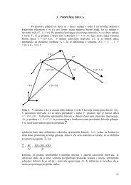
The excess pore-pressure distribution along the 12<br />
meters <strong>of</strong> s<strong>of</strong>t clay layers after the construction <strong>of</strong> the 4.0<br />
meter fill material is visualized <strong>in</strong> Figure 4. The development<br />
<strong>of</strong> the settlements and the excess pore pressures<br />
obta<strong>in</strong>ed from the numerical model is shown <strong>in</strong> figure<br />
5 for all four conditions. As expected, the <strong>in</strong>stallation <strong>of</strong><br />
the PVD significantly decreased the consolidation time,<br />
whereas consider<strong>in</strong>g the smear effects has the opposite<br />
effect and, therefore, <strong>in</strong> order to arrive at realistic predictions,<br />
this effect has to be taken <strong>in</strong>to account.<br />
The settlement plate was <strong>in</strong>stalled and measurements<br />
started after the <strong>in</strong>stallation <strong>of</strong> the 1.0 meter sand<br />
Excess Pore Pressure (KPa)<br />
-10<br />
-20<br />
-30<br />
-40<br />
-50<br />
-60<br />
-70<br />
-80<br />
I. IKHYA & H. F. SCHWEIGER: NUMERICAL MODELING OF FLOATING PREFABRICATED VERTICAL DRAINS IN LAYERED SOIL<br />
blanket and the <strong>dra<strong>in</strong>s</strong>, so no settlement read<strong>in</strong>gs were<br />
taken for this stage <strong>of</strong> the construction. The settlements<br />
obta<strong>in</strong>ed from the numerical prediction and measured<br />
<strong>in</strong> the field are compared <strong>in</strong> figure 6. It can be seen that<br />
a good agreement between the field measurement and<br />
the numerical prediction could be achieved, for both<br />
full and partial penetration (L/H=0.7) <strong>of</strong> the PVD when<br />
tak<strong>in</strong>g the smear effect <strong>in</strong>to account. It is clear that the<br />
length <strong>of</strong> the dra<strong>in</strong> can be reduced by up to 30% without<br />
significantly affect<strong>in</strong>g the consolidation process for<br />
double dra<strong>in</strong>age—two soil-layer conditions when the<br />
second layer is stiffer and has a higher permeability than<br />
the first layer.<br />
Figure 4. Excess pore-pressure distribution after the placement <strong>of</strong> 4.0 meter fill material.<br />
Axisymmetric Model <strong>of</strong> Cirebon Power Plant Embankment<br />
1 10 100 1000 10000<br />
0<br />
Time (days)<br />
Without PVD<br />
Only PVD<br />
PVD+Smear<br />
Float<strong>in</strong>g PVD (L/H=0.7)<br />
Figure 5. Excess pore-pressure and consolidation curves for all conditions.<br />
Vertical Displacement (m)<br />
1 10 100 1000 10000<br />
0<br />
-0.1<br />
-0.2<br />
-0.3<br />
-0.4<br />
-0.5<br />
-0.6<br />
-0.7<br />
-0.8<br />
Axisymmetric Model <strong>of</strong> Cirebon Power Plant Embankment<br />
Time (days)<br />
Without PVD<br />
Only PVD<br />
PVD+Smear<br />
Float<strong>in</strong>g PVD (L/H=0.7)<br />
ACTA GEOTECHNICA SLOVENICA, 2012/2 29.
I. IKHYA & H. F. SCHWEIGER: NUMERICAL MODELING OF FLOATING PREFABRICATED VERTICAL DRAINS IN LAYERED SOIL<br />
Vertical Displacement (m)<br />
-0.1<br />
-0.2<br />
-0.3<br />
-0.4<br />
-0.5<br />
-0.6<br />
-0.7<br />
-0.8<br />
Figure 6. Comparison <strong>of</strong> settlements between the numerical prediction and field measurements.<br />
4 FLOATING PVD IN TWO SOIL<br />
LAYERS<br />
In this section, three different cases will be numerically<br />
<strong>in</strong>vestigated to look at the <strong>in</strong>fluence <strong>of</strong> <strong>float<strong>in</strong>g</strong> PVDs<br />
on consolidation <strong>in</strong> a two-soil-layer condition. Figure<br />
7 shows the three conditions analysed: first, a homogeneous<br />
soil layer, second, two soil layers where the lower<br />
layer is stiffer and more permeable than the upper layer,<br />
and third, the situation when the upper layer is stiffer<br />
and more permeable than the lower layer. The <strong>in</strong>fluence<br />
<strong>of</strong> the stiffness and the permeability will also be evaluated.<br />
F<strong>in</strong>ally, the double and s<strong>in</strong>gle dra<strong>in</strong>age conditions<br />
will be exam<strong>in</strong>ed for the above three cases. The results<br />
Figure 7. Illustration <strong>of</strong> three different cases <strong>of</strong> <strong>float<strong>in</strong>g</strong> PVDs <strong>in</strong> two soil layers for one- and two-way dra<strong>in</strong>age.<br />
30. ACTA GEOTECHNICA SLOVENICA, 2012/2<br />
0<br />
<strong>Numerical</strong> Model and Field Measurement<br />
0 50 100 150 200 250 300<br />
Time (days)<br />
Full Penetration (L/H=1.0)<br />
FLOATING PVD (L/H=0.7)<br />
Field Measurement<br />
from this model will be evaluated <strong>in</strong> order to determ<strong>in</strong>e<br />
the optimum penetration depth (L/H), without<br />
significantly affect<strong>in</strong>g the consolidation process. Table 3<br />
summarizes all the analysed comb<strong>in</strong>ations.<br />
4.1 DOUBLE DRAINAGE CONDITION<br />
In this section, the effect <strong>of</strong> <strong>float<strong>in</strong>g</strong> PVDs <strong>in</strong> a double<br />
dra<strong>in</strong>age, two-soil-layers condition, on consolidation is<br />
numerically <strong>in</strong>vestigated. Here, the bottom boundary is<br />
open for flow. The result from this model will be evaluated<br />
so as to determ<strong>in</strong>e the optimum penetration depth<br />
(L/H), without significantly affect<strong>in</strong>g the consolidation<br />
process.
II<br />
III<br />
Model<br />
I<br />
Table 3. Comb<strong>in</strong>ation <strong>of</strong> cases for modell<strong>in</strong>g <strong>float<strong>in</strong>g</strong> PVDs <strong>in</strong> two soil layers for one- and two-way dra<strong>in</strong>age conditions.<br />
E50 ref = Eoed ref<br />
kN/m 2<br />
I. IKHYA & H. F. SCHWEIGER: NUMERICAL MODELING OF FLOATING PREFABRICATED VERTICAL DRAINS IN LAYERED SOIL<br />
Soil Layer I Soil Layer II<br />
Eur ref<br />
kh = kv E50 ref = Eoed ref<br />
kN/m 2 m/s kN/m 2<br />
The excess pore-pressure distributions for homogeneous<br />
and two soil layers are visualized <strong>in</strong> Figure 8.<br />
As expected, excess pore-pressure dissipation <strong>in</strong> the<br />
soil layer that has a high stiffness and permeability is<br />
faster than <strong>in</strong> the soil layer hav<strong>in</strong>g a low stiffness and<br />
permeability. For the <strong>float<strong>in</strong>g</strong> PVD conditions it is clear<br />
that the <strong>vertical</strong> flow is predom<strong>in</strong>ant <strong>in</strong> the unimproved<br />
area under the PVD tip, which has an <strong>in</strong>fluence on the<br />
consolidation time.<br />
The settlement curves from the numerical model for PVD<br />
<strong>in</strong>stallation with vary<strong>in</strong>g the depth <strong>of</strong> penetration are<br />
shown <strong>in</strong> figures 9 and 10. It is clear that for a homogeneous<br />
layer (model 1), the dra<strong>in</strong> length can be reduced by<br />
up to 20% without significantly affect<strong>in</strong>g the consolidation<br />
Eur ref<br />
kh = kv<br />
kN/m 2 m/s<br />
Remarks<br />
1000 3000 1.9x10 -9 1000 3000 1.9x10 -9 Homogeneous soil layer<br />
A 1000 3000 1.9x10 -9 1000 3000 5.0x10 -9 Value <strong>of</strong> soil permeability <strong>in</strong> layer II is higher than layer I<br />
B 1000 3000 1.9x10 -9 3000 9000 1.9x10 -9 Value <strong>of</strong> soil stiffness <strong>in</strong> layer II is higher than layer I<br />
C 1000 3000 1.9x10 -9 3000 9000 5.0x10 -9 Value <strong>of</strong> soil stiffness and permeability <strong>in</strong> layer II are higher than layer I<br />
A 1000 3000 5.0x10 -9 1000 3000 1.9x10 -9 Value <strong>of</strong> soil permeability <strong>in</strong> layer I is higher than layer II<br />
B 3000 9000 1.9x10 -9 1000 3000 1.9x10 -9 Value <strong>of</strong> soil stiffness <strong>in</strong> layer I is higher than layer II<br />
C 3000 9000 5.0x10 -9 1000 3000 1.9x10 -9 Value <strong>of</strong> soil stiffness and permeability <strong>in</strong> layer I are higher than layer II<br />
process (L/H = 0.8). This result corresponds to the report<br />
<strong>of</strong> Indraratna and Rujikiatkamjorn [7]. For the two-soillayer<br />
condition where the second layer is stiffer and more<br />
permeable than the first layer (model 2; IIA, IIB, IIC),<br />
the dra<strong>in</strong> length can be shortened by 30–40% without<br />
affect<strong>in</strong>g the consolidation process (L/H = 0.7 – 0.6)<br />
significantly. In contrast, for the two-soil-layer condition<br />
where the first layer is stiffer and more permeable than the<br />
second layer (model 3; IIIA, IIIB, IIIC), the dra<strong>in</strong> length<br />
can be reduced by only 10–20% without significantly<br />
affect<strong>in</strong>g the consolidation process (L/H = 0.9 – 0.8). It<br />
is <strong>in</strong>terest<strong>in</strong>g to note that the differences <strong>in</strong> stiffness and<br />
permeability <strong>in</strong> the two-soil-layer condition have an <strong>in</strong>fluence<br />
on the optimum penetration depth (L/H), especially<br />
<strong>in</strong> the unimproved area below the PVD tip.<br />
Figure 8. Excess pore-pressure distribution for homogeneous and two soil layers for double dra<strong>in</strong>age conditions.<br />
ACTA GEOTECHNICA SLOVENICA, 2012/2 31.
I. IKHYA & H. F. SCHWEIGER: NUMERICAL MODELING OF FLOATING PREFABRICATED VERTICAL DRAINS IN LAYERED SOIL<br />
Degree <strong>of</strong> Consolidation<br />
Degree <strong>of</strong> Consolidation<br />
Degree <strong>of</strong> Consolidation<br />
Degree <strong>of</strong> Consolidation<br />
Figure 9. Settlement curves for homogeneous and double dra<strong>in</strong>age conditions for vary<strong>in</strong>g PVD penetration depth.<br />
Figure 10. Settlement curves for two soil layers and double dra<strong>in</strong>age conditions for vary<strong>in</strong>g PVD penetration depth.<br />
32. ACTA GEOTECHNICA SLOVENICA, 2012/2<br />
0<br />
0.1<br />
0.2<br />
0.3<br />
0.4<br />
0.5<br />
0.6<br />
0.7<br />
0.8<br />
0.9<br />
1<br />
Model I (Homogeneous Layer & Double Dra<strong>in</strong>ed)<br />
1 10 100 1000 10000<br />
Soil Layer I<br />
=<br />
Soil Layer II<br />
E1&k1<br />
Homogeneous<br />
Layer<br />
1 10<br />
Model II-A (Double Dra<strong>in</strong>ed)<br />
100 1000 10000<br />
0<br />
0.1<br />
0.2<br />
0.3<br />
L/H=1.0 (Full Penetration)<br />
L/H=0.9<br />
0.4<br />
L/H=0.8<br />
0.5<br />
L/H=0.7<br />
0.6 Soil Layer I<br />
L/H=0.6<br />
E1&k1<br />
L/H=0.5<br />
0.7<br />
Without PVD<br />
0.8<br />
k2>k1<br />
0.9<br />
1<br />
Soil Layer II<br />
E1&k2<br />
Time (days)<br />
1 10<br />
Model II-B (Double Dra<strong>in</strong>ed)<br />
100 1000 10000<br />
0<br />
0.1<br />
0.2<br />
0.3<br />
L/H=1.0 (Full Penetration)<br />
L/H=0.9<br />
0.4<br />
L/H=0.8<br />
0.5<br />
L/H=0.7<br />
0.6 Soil Layer I<br />
L/H=0.6<br />
E1&k1<br />
L/H=0.5<br />
0.7<br />
Without PVD<br />
0.8<br />
E2>E1<br />
0.9<br />
1<br />
Soil Layer II<br />
E2&k1<br />
Time (days)<br />
1 10<br />
Model II-C (Double Dra<strong>in</strong>ed)<br />
100 1000 10000<br />
0<br />
0.1<br />
0.2<br />
0.3<br />
L/H=1.0 (Full Penetration)<br />
L/H=0.9<br />
0.4<br />
L/H=0.8<br />
0.5<br />
L/H=0.7<br />
0.6 Soil Layer I<br />
L/H=0.6<br />
E1&k1<br />
L/H=0.5<br />
0.7<br />
Without PVD<br />
0.8<br />
E2>E1 & k2>k1<br />
0.9<br />
1<br />
Soil Layer II<br />
E2&k2<br />
Time (days)<br />
Time (days)<br />
Degree <strong>of</strong> Consolidation<br />
Degree <strong>of</strong> Consolidation<br />
Degree <strong>of</strong> Consolidation<br />
L/H=1.0 (Full Penetration)<br />
L/H=0.9<br />
L/H=0.8<br />
L/H=0.7<br />
L/H=0.6<br />
L/H=0.5<br />
Without PVD<br />
1 10<br />
Model III-A (Double Dra<strong>in</strong>ed)<br />
100 1000 10000<br />
0<br />
0.1<br />
0.2<br />
0.3<br />
L/H=1.0 (Full Penetration)<br />
L/H=0.9<br />
0.4<br />
L/H=0.8<br />
0.5<br />
L/H=0.7<br />
0.6 Soil Layer I<br />
L/H=0.6<br />
E1&k2<br />
L/H=0.5<br />
0.7<br />
Without PVD<br />
0.8<br />
k2>k1<br />
0.9<br />
1<br />
Soil Layer II<br />
E1&k1<br />
Time (days)<br />
1 10<br />
Model III-B (Double Dra<strong>in</strong>ed)<br />
100 1000 10000<br />
0<br />
0.1<br />
0.2<br />
0.3<br />
L/H=1.0 (Full Penetration)<br />
L/H=0.9<br />
0.4<br />
L/H=0.8<br />
0.5<br />
L/H=0.7<br />
0.6 Soil Layer I<br />
L/H=0.6<br />
E2&k1<br />
L/H=0.5<br />
0.7<br />
Without PVD<br />
0.8<br />
E2>E1<br />
0.9<br />
1<br />
Soil Layer II<br />
E1&k1<br />
Time (days)<br />
1 10<br />
Model III-C (Double Dra<strong>in</strong>ed)<br />
100 1000 10000<br />
0<br />
0.1<br />
0.2<br />
0.3<br />
L/H=1.0 (Full Penetration)<br />
L/H=0.9<br />
0.4<br />
L/H=0.8<br />
0.5<br />
L/H=0.7<br />
0.6 Soil Layer I<br />
L/H=0.6<br />
E2&k2<br />
L/H=0.5<br />
0.7<br />
Without PVD<br />
0.8<br />
E2>E1 & k2>k1<br />
0.9<br />
1<br />
Soil Layer II<br />
E1&k1<br />
Time (days)
4.2 SINGLE DRAINAGE CONDITION<br />
In this section the effect <strong>of</strong> <strong>float<strong>in</strong>g</strong> PVDs <strong>in</strong> s<strong>in</strong>gle<br />
dra<strong>in</strong>age, two-soil-layer conditions, on consolidation<br />
is numerically <strong>in</strong>vestigated. Here, no flow across the<br />
bottom boundary is allowed.<br />
The excess pore-pressure distributions for the homogeneous<br />
and two-soil-layer conditions are shown <strong>in</strong> Figure<br />
11. A similar picture as before is obta<strong>in</strong>ed, namely that<br />
the excess pore-water dissipation <strong>in</strong> the soil layer with a<br />
high stiffness and permeability is faster than <strong>in</strong> the soil<br />
layer with a low stiffness and permeability.<br />
The settlement curves from the numerical model for a<br />
PVD <strong>in</strong>stallation with a vary<strong>in</strong>g depth <strong>of</strong> penetration<br />
are shown <strong>in</strong> figures 12 and 13. It is clear that for a<br />
homogeneous layer (model 1), the dra<strong>in</strong> length can only<br />
be reduced by up to 10% without significantly affect<strong>in</strong>g<br />
the consolidation process (L/H = 0.9). This is <strong>in</strong> l<strong>in</strong>e with<br />
Chai et al. [10], who suggested not choos<strong>in</strong>g <strong>float<strong>in</strong>g</strong><br />
PVDs <strong>in</strong> one-way dra<strong>in</strong>age conditions. For the two-soillayer<br />
condition where the second layer is more stiff and<br />
permeable than the first layer (model 2; IIA, IIB, IIC),<br />
the dra<strong>in</strong> length can be shortened by 15–25% without<br />
seriously affect<strong>in</strong>g the consolidation process (L/H =<br />
0.85 – 0.75). In contrast, for the two-soil-layer condition<br />
Figure 11. Excess pore-pressure distribution for homogeneous and two soil layers for s<strong>in</strong>gle dra<strong>in</strong>age condition.<br />
Degree <strong>of</strong> Consolidation<br />
0<br />
0.1<br />
0.2<br />
0.3<br />
0.4<br />
0.5<br />
0.6<br />
0.7<br />
0.8<br />
0.9<br />
1<br />
I. IKHYA & H. F. SCHWEIGER: NUMERICAL MODELING OF FLOATING PREFABRICATED VERTICAL DRAINS IN LAYERED SOIL<br />
1 10 100 1000 10000 100000<br />
Soil Layer I<br />
=<br />
Soil Layer II<br />
E1&k1<br />
Homogeneous<br />
Layer<br />
Model I (Homogeneous Layer & S<strong>in</strong>gle Dra<strong>in</strong>ed)<br />
Time (days)<br />
L/H=1.0 (Full Penetration)<br />
L/H=0.9<br />
L/H=0.8<br />
L/H=0.7<br />
L/H=0.6<br />
L/H=0.5<br />
Without PVD<br />
Figure 12. Settlement curves for homogeneous and s<strong>in</strong>gle dra<strong>in</strong>age conditions for vary<strong>in</strong>g PVD penetration depth.<br />
ACTA GEOTECHNICA SLOVENICA, 2012/2 33.
I. IKHYA & H. F. SCHWEIGER: NUMERICAL MODELING OF FLOATING PREFABRICATED VERTICAL DRAINS IN LAYERED SOIL<br />
Degree <strong>of</strong> Consolidation<br />
Degree <strong>of</strong> Consolidation<br />
Degree <strong>of</strong> Consolidation<br />
Model II-A (S<strong>in</strong>gle Dra<strong>in</strong>ed)<br />
1 10 100 1000 10000 100000<br />
0<br />
0.1<br />
0.2<br />
0.3<br />
L/H=1.0 (Full Penetration)<br />
L/H=0.9<br />
0.4<br />
L/H=0.8<br />
0.5<br />
L/H=0.7<br />
0.6 Soil Layer I<br />
L/H=0.6<br />
E1&k1<br />
L/H=0.5<br />
0.7<br />
Without PVD<br />
0.8<br />
k2>k1<br />
0.9<br />
1<br />
Soil Layer II<br />
E1&k2<br />
Time (days)<br />
Model II-B (S<strong>in</strong>gle Dra<strong>in</strong>ed)<br />
1 10 100 1000 10000 100000<br />
0<br />
0.1<br />
0.2<br />
0.3<br />
L/H=1.0 (Full Penetration)<br />
L/H=0.9<br />
0.4<br />
L/H=0.8<br />
0.5<br />
L/H=0.7<br />
0.6 Soil Layer I<br />
L/H=0.6<br />
E1&k1<br />
L/H=0.5<br />
0.7<br />
Without PVD<br />
0.8<br />
E2>E1<br />
0.9<br />
1<br />
Soil Layer II<br />
E2&k1<br />
Time (days)<br />
Model II-C (S<strong>in</strong>gle Dra<strong>in</strong>ed)<br />
1 10 100 1000 10000 100000<br />
0<br />
0.1<br />
0.2<br />
0.3<br />
L/H=1.0 (Full Penetration)<br />
L/H=0.9<br />
0.4<br />
L/H=0.8<br />
0.5<br />
L/H=0.7<br />
0.6 Soil Layer I<br />
L/H=0.6<br />
E1&k1<br />
L/H=0.5<br />
0.7<br />
Without PVD<br />
0.8<br />
E2>E1 & k2>k1<br />
0.9<br />
1<br />
Soil Layer II<br />
E2&k2<br />
Time (days)<br />
Figure 13. Settlement curves for two soil layers and s<strong>in</strong>gle dra<strong>in</strong>age condition for vary<strong>in</strong>g PVD penetration depth.<br />
where the first layer is stiffer and more permeable than<br />
the second layer (model 3; IIIA, IIIB, IIIC), the dra<strong>in</strong><br />
length can only be reduced by about 10% without affect<strong>in</strong>g<br />
the consolidation process (L/H = 1.0–0.9). Based on<br />
this numerical study it can be concluded that for s<strong>in</strong>gle<br />
dra<strong>in</strong>age conditions, only model 2, i.e., if the second<br />
layer is stiffer and more permeable than the first layer,<br />
can the use <strong>of</strong> <strong>float<strong>in</strong>g</strong> PVDs be recommended.<br />
5 CONCLUSIONS<br />
<strong>Numerical</strong> results from a study <strong>of</strong> <strong>float<strong>in</strong>g</strong> PVDs <strong>in</strong> two<br />
soil layers for double and s<strong>in</strong>gle dra<strong>in</strong>age conditions were<br />
exam<strong>in</strong>ed to determ<strong>in</strong>e the optimum penetration depth<br />
for the PVDs. It is <strong>in</strong>terest<strong>in</strong>g to note that the differences<br />
<strong>in</strong> stiffness and permeability <strong>in</strong> the two-soil-layer condition,<br />
especially <strong>in</strong> the unimproved area below the PVD<br />
tip, have an <strong>in</strong>fluence on the optimum penetration depth<br />
34. ACTA GEOTECHNICA SLOVENICA, 2012/2<br />
Degree <strong>of</strong> Consolidation<br />
Degree <strong>of</strong> Consolidation<br />
Degree <strong>of</strong> Consolidation<br />
Model III-A (S<strong>in</strong>gle Dra<strong>in</strong>ed)<br />
1 10 100 1000 10000 100000<br />
0<br />
0.1<br />
0.2<br />
0.3<br />
L/H=1.0 (Full Penetration)<br />
L/H=0.9<br />
0.4<br />
L/H=0.8<br />
0.5<br />
L/H=0.7<br />
0.6 Soil Layer I<br />
L/H=0.6<br />
E1&k2<br />
L/H=0.5<br />
0.7<br />
Without PVD<br />
0.8<br />
k2>k1<br />
0.9<br />
1<br />
Soil Layer II<br />
E1&k1<br />
Time (days)<br />
Model III-B (S<strong>in</strong>gle Dra<strong>in</strong>ed)<br />
1 10 100 1000 10000 100000<br />
0<br />
0.1<br />
0.2<br />
0.3<br />
L/H=1.0 (Full Penetration)<br />
L/H=0.9<br />
0.4<br />
L/H=0.8<br />
0.5<br />
L/H=0.7<br />
0.6 Soil Layer I<br />
L/H=0.6<br />
E2&k1<br />
L/H=0.5<br />
0.7<br />
Without PVD<br />
0.8<br />
E2>E1<br />
0.9<br />
1<br />
Soil Layer II<br />
E1&k1<br />
Time (days)<br />
Model III-C (S<strong>in</strong>gle Dra<strong>in</strong>ed)<br />
1 10 100 1000 10000 100000<br />
0<br />
0.1<br />
0.2<br />
0.3<br />
L/H=1.0 (Full Penetration)<br />
L/H=0.9<br />
0.4<br />
L/H=0.8<br />
0.5<br />
L/H=0.7<br />
0.6 Soil Layer I<br />
L/H=0.6<br />
E2&k2<br />
L/H=0.5<br />
0.7<br />
Without PVD<br />
0.8<br />
E2>E1 & k2>k1<br />
0.9<br />
1<br />
Soil Layer II<br />
E1&k1<br />
Time (days)<br />
(L/H) <strong>in</strong> order to achieve the same consolidation time.<br />
It was found <strong>in</strong> this study that for double dra<strong>in</strong>age conditions<br />
<strong>in</strong> a homogeneous soil layer (model 1), the dra<strong>in</strong> length<br />
can be reduced by up to 20% without significantly affect<strong>in</strong>g<br />
the consolidation process (L/H = 0.8). For a two-soil-layer<br />
condition where the second layer is stiffer and more permeable<br />
than the first layer (model 2; IIA, IIB, IIC), the dra<strong>in</strong><br />
length can be shortened by 30–40% (L/H = 0.7–0.6). In<br />
contrast, for a two-soil-layer condition where first layer is<br />
stiffer and more permeable than the second layer (model<br />
3; IIIA, IIIB, IIIC), the dra<strong>in</strong> length can be reduced by only<br />
10–20% (L/H=0.9–0.8). For s<strong>in</strong>gle dra<strong>in</strong>age conditions it<br />
is possible to use a <strong>float<strong>in</strong>g</strong> PVD only if the second layer is<br />
stiffer and/or more permeable than the first layer.<br />
This study has shown that a good agreement between<br />
field measurements and numerical predictions for settlements<br />
<strong>in</strong> both full and partial penetration conditions
can be achieved. For the presented case study the dra<strong>in</strong><br />
length could be reduced by up to 30% without significantly<br />
affect<strong>in</strong>g the consolidation process (L/H = 0.7).<br />
ACKNOWLEDGEMENTS<br />
The authors wish to thank PT. Soilens, PT. Doosan<br />
Heavy Industries Indonesia, PT. Cirebon Electric Power,<br />
PT. Tripatra Eng<strong>in</strong>eers and Constructors for provid<strong>in</strong>g<br />
the case-study data <strong>in</strong> this paper. The authors would also<br />
like to thank Ir. Padmono, P.E., (PT. Soilens Bandung)<br />
for his time dur<strong>in</strong>g a detailed discussion <strong>of</strong> the site<br />
conditions and parameters. The work reported <strong>in</strong> this<br />
paper was supported by North-South-Dialogue scholarship<br />
programme from Österreichische Akademische<br />
Austauschdienst (ÖAD) for the first author as part <strong>of</strong> a<br />
Ph.D. study at Graz University <strong>of</strong> Technology, Austria.<br />
REFERENCES<br />
I. IKHYA & H. F. SCHWEIGER: NUMERICAL MODELING OF FLOATING PREFABRICATED VERTICAL DRAINS IN LAYERED SOIL<br />
[1] Barry, A.J., Rahadian, H., Rachlan, A. (2002). The<br />
Indonesian geoguides. Symposium on Geotechnical<br />
Eng<strong>in</strong>eer<strong>in</strong>g, Bangkok.<br />
[2] Runesson, K,, Hansbo. S., Wiberg, N.E. (1985). The<br />
efficiency <strong>of</strong> partially penetrat<strong>in</strong>g <strong>vertical</strong> <strong>dra<strong>in</strong>s</strong>.<br />
Géotechnique Journal, Vol. 35, No. 4, pp. 511-516.<br />
[3] Onoue, A. (1988). Consolidation <strong>of</strong> multi<strong>layered</strong><br />
anisotropic soils by <strong>vertical</strong> <strong>dra<strong>in</strong>s</strong> with well resistance.<br />
Journal <strong>of</strong> The Japanese Geotechnical Society:<br />
Soils and Foundations, Vol. 28, No. 3, pp. 75-90.<br />
[4] Nakano, H., Okuie, H. (1991). Consolidation by<br />
us<strong>in</strong>g a long dra<strong>in</strong>age wells with partial penetration.<br />
Journal <strong>of</strong> The Japanese Geotechnical Society:<br />
Soils and Foundations, Vol. 39, No. 8, pp. 23-28.<br />
[5] Tang, X.W., Onitsuka, K. (1998). Consolidation <strong>of</strong><br />
ground with partially penetrated <strong>vertical</strong> <strong>dra<strong>in</strong>s</strong>.<br />
International Journal <strong>of</strong> Geotechnical Eng<strong>in</strong>eer<strong>in</strong>g,<br />
Vol. 29, No. 2, pp. 209-231.<br />
[6] Tang, X.W. (2004). Comparison <strong>of</strong> partially<br />
penetrated open and closed ended <strong>vertical</strong> <strong>dra<strong>in</strong>s</strong>.<br />
Proceed<strong>in</strong>g <strong>of</strong> the 3 rd Asian Regional Conference on<br />
Geosynthetics: Now and Future <strong>of</strong> Geosynthetics <strong>in</strong><br />
Civil Eng<strong>in</strong>eer<strong>in</strong>g, Seoul, pp. 291-297.<br />
[7] Indraratna, B., Rujikiatkamjorn, C. (2008). Effects<br />
<strong>of</strong> partially penetrat<strong>in</strong>g <strong>prefabricated</strong> <strong>vertical</strong><br />
<strong>dra<strong>in</strong>s</strong> and load<strong>in</strong>g patterns on vacuum consolidation,<br />
In: Reddy, K.R., Khire, M.V., Alshawabkeh,<br />
A.N. (Eds.). Proceed<strong>in</strong>g <strong>of</strong> the GeoCongress:<br />
Geosusta<strong>in</strong>ability and Geohazard Mitigation, ASCE,<br />
Orleans, pp. 596-603.<br />
[8] Hart, E.G., Kondner. R.L., Boyer, W.C. (1958).<br />
Analysis for partially penetrat<strong>in</strong>g sand <strong>dra<strong>in</strong>s</strong>.<br />
Journal <strong>of</strong> Soil Mechanics and Foundation Division:<br />
Proceed<strong>in</strong>gs <strong>of</strong> ASCE, Vol. 84, No. 4, pp. 1-15.<br />
[9] Zeng, G.X., Xie, K.H. (1989). New development <strong>of</strong><br />
the <strong>vertical</strong> dra<strong>in</strong> theories. Proceed<strong>in</strong>g <strong>of</strong> the 12 th<br />
ICSMFE, Rio de Janeiro, Vol. 2, pp. 1435-1438.<br />
[10] Chai, J.C., Miura, N., Kirekawa, T., H<strong>in</strong>o, T. (2009).<br />
Optimum PVD <strong>in</strong>stallation depth for two-way<br />
dra<strong>in</strong>age deposit. International Journal <strong>of</strong> Geomechanics<br />
and Eng<strong>in</strong>eer<strong>in</strong>g, Vol. 1, No. 3, pp. 179-191.<br />
[11] Geng, X.Y., Indraratna, B., Rujikiatkamjorn, C.<br />
(2011). Effectiveness <strong>of</strong> partially penetrat<strong>in</strong>g<br />
<strong>vertical</strong> <strong>dra<strong>in</strong>s</strong> under a comb<strong>in</strong>ed surcharge and<br />
vacuum preload<strong>in</strong>g. Canadian Geotechnical Journal,<br />
Vol. 48, pp. 970-983.<br />
[12] Unsworth, R. (Eds). (2008). Mar<strong>in</strong>e environment<br />
report <strong>of</strong> the Cirebon IPP coal fired power station<br />
for PT. Cirebon Electric Power. S<strong>in</strong>clair Knight<br />
Merz, Brisbane. (QE09421.02).<br />
[13] Padmono, P. (Eds). (2008a). Review <strong>of</strong> settlement<br />
<strong>in</strong>strumentation report <strong>of</strong> the 1x660 MW coal<br />
fired Cirebon power plant project for PT. Doosan<br />
Heavy Industries Indonesia. PT. Soilens, Bandung.<br />
(2238-B & 2428).<br />
[14] Padmono, P. (Eds). (2008b). Soil <strong>in</strong>vestigation II<br />
report <strong>of</strong> the 1x660 MW coal fired Cirebon power<br />
plant project for PT. Doosan Heavy Industries<br />
Indonesia. PT. Soilens, Bandung. (2338-B & 2428).<br />
[15] Barry, A.J., Rachlan, A. (2001). Embankments on<br />
s<strong>of</strong>t soils <strong>in</strong> North Java. Proceed<strong>in</strong>g <strong>of</strong> International<br />
Conference on In Situ Measurement <strong>of</strong> Soil Properties<br />
and Case Histories, Bali.<br />
[16] Barry, A.J., Rahadian, H., Rachlan, A. (2003). The<br />
embankments on North Java s<strong>of</strong>t clay. Proceed<strong>in</strong>g<br />
<strong>of</strong> the 12 th Asian Regional Conference, S<strong>in</strong>gapore.<br />
[17] Padmono, P. (Eds). (2006). Prelim<strong>in</strong>ary soil <strong>in</strong>vestigation<br />
report <strong>of</strong> the IPP 1x660 MW coal fired<br />
steam Cirebon power plant project for PT. Tripatra<br />
Eng<strong>in</strong>eers and Constructors. PT. Soilens, Bandung.<br />
[18] Padmono, P. (Eds). (2007). Soil <strong>in</strong>vestigation I<br />
report <strong>of</strong> the Cirebon thermal power plant project<br />
for PT. Cirebon Electric Power. PT. Soilens, Bandung.<br />
(2338 & 2358).<br />
[19] Br<strong>in</strong>kgreve, R.B.J., Swolf, W.M., Eng<strong>in</strong>, E. (Eds).<br />
(2010). Plaxis 2D 2010 user manual: F<strong>in</strong>ite element<br />
code for soil and rock analyses. Plaxis bv., Netherland.<br />
[20] Schanz, T., Vermeer, P.A., Bonnier, P.G. (1999). The<br />
harden<strong>in</strong>g soil model: formulation and verification.<br />
Proceed<strong>in</strong>g <strong>of</strong> the International Symposium<br />
Beyond 2000 <strong>in</strong> Computational Geotechnics – 10<br />
Years <strong>of</strong> Plaxis, Amsterdam, pp. 281-296.<br />
[21] Hansbo, S. (1979). Consolidation <strong>of</strong> clay by bandshaped<br />
<strong>prefabricated</strong> <strong>dra<strong>in</strong>s</strong>. Ground Eng<strong>in</strong>eer<strong>in</strong>g,<br />
Vol. 12, No. 5, pp. 16-25.<br />
[22] Chai, J.C., Miura, N. (1999). Investigation <strong>of</strong><br />
factors affect<strong>in</strong>g <strong>vertical</strong> dra<strong>in</strong> behavior. Journal <strong>of</strong><br />
Geotechnical and Geoenvironmental Eng<strong>in</strong>eer<strong>in</strong>g,<br />
Vol. 125, No. 3, pp. 216-226.<br />
ACTA GEOTECHNICA SLOVENICA, 2012/2 35.