TECHNICAL NOTES ON THE EEC-IV MCU - Auto diagnostics
TECHNICAL NOTES ON THE EEC-IV MCU - Auto diagnostics
TECHNICAL NOTES ON THE EEC-IV MCU - Auto diagnostics

Create successful ePaper yourself
Turn your PDF publications into a flip-book with our unique Google optimized e-Paper software.
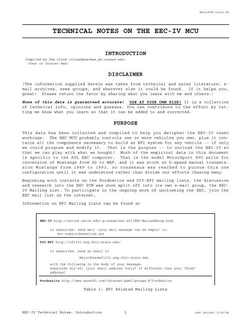
<strong>TECHNICAL</strong> <strong>NOTES</strong> <strong>ON</strong> <strong>THE</strong> <strong>EEC</strong>-<strong>IV</strong> <strong>MCU</strong><br />
INTRODUCTI<strong>ON</strong><br />
Compiled by Tom Cloud <br />
(font is Courier New)<br />
DISCLAIMER<br />
Eectch98-Intro.fm<br />
(The information supplied herein was taken from technical and sales literature, email<br />
archives, news groups, and wherever else it could be found. If it helps you,<br />
great! Please return the favor by sharing what you learn with me and others.)<br />
None of this data is guaranteed accurate! USE AT YOUR OWN RISK! It is a collection<br />
of technical info, opinions and guesses. You can contribute to the effort by letting<br />
me know what you learn so that it can be added to and corrected.<br />
PURPOSE<br />
This data has been collected and compiled to help you decipher the <strong>EEC</strong>-<strong>IV</strong> inner<br />
workings. The <strong>EEC</strong> <strong>MCU</strong> probably controls one or more vehicles you own, plus it contains<br />
all the components necessary to build an EFI system for any vehicle -- if only<br />
we could program and modify it. That is the purpose -- to uncloak the <strong>EEC</strong>-<strong>IV</strong> so<br />
that we can play with what we bought! Much of the empirical data in this document<br />
is specific to the A9L <strong>EEC</strong> computer. That is the model MotorSport SVO sells for<br />
conversion of Mustangs from SD to MAF, and it was stock on 5-speed manual transmission<br />
Mustangs from 1989 to 1993, so consensus was reached to pursue this one<br />
configuration until it was understood rather than divide our efforts chasing many.<br />
Beginning with contacts on the Fordnatics and DIY-EFI mailing lists, the discussion<br />
and research into the <strong>EEC</strong> PCM was soon split off into its own e-mail group, the <strong>EEC</strong>-<br />
<strong>IV</strong> Mailing List. To participate in the ongoing work of uncloaking the <strong>EEC</strong>, join the<br />
<strong>EEC</strong> mail list on the internet.<br />
Information on EFI Mailing Lists can be found at<br />
<strong>EEC</strong>-<strong>IV</strong> http://eelink.umich.edu/~p-nowak/eec-efi/<strong>EEC</strong>-Mailadddrop.html<br />
to subscribe, send mail (your mail message can be empty) to:<br />
eec-subscribe@eelink.net<br />
DIY-EFI http://efi332.eng.ohio-state.edu/<br />
to subscribe, send an email to<br />
Majordomo@efi332.eng.ohio-state.edu<br />
with the following in the body of your message:<br />
subscribe diy-efi [your email address *only* if different than your "From"<br />
address]<br />
Fordnatics http://www.neosoft.com/internet/paml/groups.F/fordnatics<br />
Table 1: EFI Related Mailing Lists<br />
<strong>EEC</strong>-<strong>IV</strong> Technical Notes: Introduction 1 last edited: 9/29/98
To subscribe, send email to<br />
fordnatics-request@lists.best.com<br />
and in the body of the message, put the word “ subscribe”<br />
Table 1: EFI Related Mailing Lists<br />
OVERVIEW<br />
Eectch98-Intro.fm<br />
The <strong>EEC</strong>-<strong>IV</strong> design began in 1978 and was first introduced in 1983 in the 1.6L Escort,<br />
Lynx, EXP and LN7 cars. It has gone through several major physical changes, the<br />
earliest using a fairly simple two board design with through hole soldered components<br />
while the last are more current in technology, showing extensive use of<br />
surface mount components and a much more finished and complex appearance. In<br />
between, there appears to be a variety of mother/daughter board and other designs.<br />
Still, they are all called <strong>EEC</strong>-<strong>IV</strong>, although somewhere in its life there was a Ford<br />
P/N generational change.<br />
The reader is referred to the SAE paper #820900, noted in the reference section at<br />
the end of this document, for a much more detailed description of the design goals<br />
and operation of the <strong>EEC</strong>-<strong>IV</strong> <strong>MCU</strong>.<br />
One person wrote: "The processor used is the 8065 along with several supporting<br />
peripheral chips like the DUCE chip which can provide up to 8 PWM outputs and the<br />
DARC chip which has 6 channels of timer capture inputs." (Is he talking about the<br />
<strong>EEC</strong>-V here ?)<br />
The <strong>EEC</strong> module is rated to 80 o C (185 o F) continuous, 100 o C intermittent, so it will<br />
be much happier and live longer in the passenger compartment. Some of the later generation<br />
15 and 18 MHz Motorola 8061 processors have a bus loading/edge timing<br />
sensitivity that only gets worse at high temperature, so it’s best to keep the <strong>EEC</strong><br />
in a more hospitable environment. Additionally, mounting the <strong>EEC</strong> in the passenger<br />
compartment will give you better access to the J3 test port, which is where you’ll<br />
be plugging in an after-market module or any test / modification device.<br />
The J3 test port on the side of the ECU box is for developers to plug into -- this<br />
is how the after-market chipmakers and others get into the box. The test connector<br />
has the micro-controller’s multiplexed address/data bus signals on it. It also,<br />
very conveniently, has a PROM disable signal. So the chip makers design something<br />
that hangs off that connector, disables the computer’s PROM, and substitutes its own<br />
PROM in its place.<br />
The reader is encouraged to investigate the Intel 8096 (MCS-96) literature for<br />
greater insight into the 8061 processor used in the <strong>EEC</strong>. One document available<br />
from their web site is "27006102.pdf" entitled "APPLICATI<strong>ON</strong> NOTE; AP-248; Using The<br />
8096"; Order Number: 270061-002. There are many other related documents available<br />
from Intel -- including the use of the A-D converter, the implementation of "fuzzy<br />
logic", instrumenting and controlling automotive applications, and other topics.<br />
Also, this author has posted a synopsis of the 8096 pinouts and instruction set<br />
which is available at several web sites.<br />
ACKNOWLEDGEMENTS / C<strong>ON</strong>TRIBUTORS<br />
Gotta love this job - I collect all the work other people have done and then get to<br />
take the credit for it! Someone sent this to me via e-mail and I thought it appropriate<br />
here: “To steal ideas from one person is plagiarism; to steal from many is<br />
research”.<br />
<strong>EEC</strong>-<strong>IV</strong> Technical Notes: Introduction 2 last edited: 9/29/98
Eectch98-Intro.fm<br />
Below is a list of the people (and/or other sources) that have either given me<br />
information I’ve used here or have provided insight or help - they’re the ones that<br />
know about this subject. Correction - a consensus was reached to omit references to<br />
any people - so, if you contributed something or are quoted in this document and<br />
want to be acknowledged, please let me know and I’ll be sure you’re mentioned in the<br />
next rev.<br />
(I’ve been doing this so long, have talked with so many people, visited so many web<br />
sites and read so much literature that I guarantee many people and sources are omitted.<br />
It’s unintentional. If you’ve been left out or you see something or someone<br />
that should be acknowledged here, please let me know right away.)<br />
* [the names were here]<br />
* Intel MCS-96 literature<br />
* Intel Application notes<br />
* AP-248; Using the 8096<br />
* "How to Understand, Service, and Modify Ford Fuel Injection and Electronic Engine<br />
Control", by Charles O. Probst<br />
* SAE paper #820900, "<strong>EEC</strong>-<strong>IV</strong> Tomorrow’s Electronic Engine Controls Today", David<br />
Hagen & Dennis Wilkie, Ford Motor Co., Dearborn, MI<br />
Date Name(s) Notes<br />
9-26-96 Subject: Intel 8061 :: <strong>EEC</strong>-<strong>IV</strong> e-mail<br />
2-7-97 Subject: <strong>EEC</strong>-<strong>IV</strong> notes e-mail<br />
2-14-1997 Subject: Ignition Writeup e-mail<br />
4-22-1997 8096_CPU.DOC 8096 op-codes, etc<br />
11-26-1997 112601.pdf<br />
9-3-1998 Eectch98-Intro.pdf rev 2<br />
Eectch98-Part1.pdf<br />
Eectch98-Part2.pdf<br />
Eectch98-Part3.pdf<br />
Eectch98-Part4.pdf<br />
Eectch98-Part5.pdf<br />
9- -1998 Eectch98.pdf rev 3 conversion to FrameMaker 5.5<br />
Table 2: Document Revision History<br />
<strong>EEC</strong>-<strong>IV</strong> Technical Notes: Introduction 3 last edited: 9/29/98
Technical Notes on the <strong>EEC</strong>-<strong>IV</strong> <strong>MCU</strong><br />
Table of contents<br />
Eectch98TOC.fm<br />
<strong>TECHNICAL</strong> <strong>NOTES</strong> <strong>ON</strong> <strong>THE</strong> <strong>EEC</strong>-<strong>IV</strong> <strong>MCU</strong> ====================================== 1<br />
INTRODUCTI<strong>ON</strong> =========================================================== 1<br />
DISCLAIMER - - - - - - - - - - - - - - - - - - - - 1<br />
PURPOSE - - - - - - - - - - - - - - - - - - - - - 1<br />
Table 1: EFI Related Mailing Lists - - - - - - - - - - - - - - 1<br />
OVERVIEW - - - - - - - - - - - - - - - - - - - - - 2<br />
ACKNOWLEDGEMENTS / C<strong>ON</strong>TRIBUTORS - - - - - - - - - - - - - 2<br />
Table 2: Document Revision History - - - - - - - - - - - - - - 3<br />
TABLE OF C<strong>ON</strong>TENTS ====================================================== 4<br />
HARDWARE =============================================================== 7<br />
<strong>THE</strong> MICROPROCESSOR / MEMORY CHIP SET: - - - - - - - - - - - 7<br />
Figure 1: 8061 Microprocessor - - - - - - - - - - - - - 7<br />
Figure 2: 8061 Major Functional Units - - - - - - - - - - - 7<br />
Figure 3: 8061 CPU - - - - - - - - - - - - - - - - - 8<br />
Figure 4: 8061 High Input Unit - - - - - - - - - - - - - 8<br />
Figure 5: High Speed Output Unit - - - - - - - - - - - - 9<br />
Figure 6: Vector to Service Routine - - - - - - - - - - - 9<br />
Figure 7: 8763 EPROM - - - - - - - - - - - - - - - - 9<br />
Figure 8: 81C61 RAM - I/O - - - - - - - - - - - - - - 10<br />
Table 3: <strong>EEC</strong> Chipset Nomenclature Legend - - - - - - - - - - - - 11<br />
Table 4: 8061 CPU Pinout - - - - - - - - - - - - - - - - - - 11<br />
Table 5: 8361 RAM/IO Pinout - - - - - - - - - - - - - - - - - 12<br />
Table 6: 87C61 RAM/IO Pinout - - - - - - - - - - - - - - - - 12<br />
Table 7: 8763 EPROM Pinout - - - - - - - - - - - - - - - - - 12<br />
Table 8: 8061 Chipset Legend - - - - - - - - - - - - - - - - 13<br />
8061 MEMORY MAP - - - - - - - - - - - - - - - - - 14<br />
8061 INSTRUCTI<strong>ON</strong>S, REGISTERS & INTERRUPTS - - - - - - - - - 14<br />
Table 9: 8096-8061/5 Instruction Differences - - - - - - - - - - - 14<br />
Table 10: 8096-8061 Op-Codes - - - - - - - - - - - - - - - - 14<br />
Table 11: Op-Code Map 00-70 - - - - - - - - - - - - - - - - - 17<br />
Table 12: Op-Code Map 80-FF - - - - - - - - - - - - - - - - - 17<br />
Table 13: 8061 Interrupt Vectors and Priorities - - - - - - - - - - 17<br />
Table 14: Register Map - - - - - - - - - - - - - - - - - - 18<br />
ECM TEST PORT (J3) - - - - - - - - - - - - - - - - 19<br />
Table 15: ECM Test Port (J3) Pinout - - - - - - - - - - - - - - 19<br />
Figure 9: J3 Service Port Connector - - - - - - - - - - 19<br />
ECM WIRING HARNESS - - - - - - - - - - - - - - - - 20<br />
Table 16: ECM CABLE PINOUT - - - - - - - - - - - - - - - - - 20<br />
Figure 10: <strong>EEC</strong> Main Connector - - - - - - - - - - - - 20<br />
SOFTWARE ============================================================== 22<br />
<strong>THE</strong> BASICS - - - - - - - - - - - - - - - - - - - 22<br />
INTERNAL DIAGNOSTICS - - - - - - - - - - - - - - - - 22<br />
FUEL C<strong>ON</strong>TROL - - - - - - - - - - - - - - - - - - 22<br />
IGNITI<strong>ON</strong> AND TIMING C<strong>ON</strong>TROL: - - - - - - - - - - - - - 24<br />
<strong>EEC</strong>-<strong>IV</strong> Technical Notes: Table of Contents last edited: 9/29/98
Technical Notes on the <strong>EEC</strong>-<strong>IV</strong> <strong>MCU</strong><br />
Eectch98TOC.fm<br />
Knock Sensor - - - - - - - - - - - - - - - - - - - - 25<br />
LIMITED OUTPUT STRATEGY (LOS) OPERATI<strong>ON</strong> - - - - - - - - - 25<br />
FUNCTI<strong>ON</strong>S / SCALARS / TABLES - - - - - - - - - - - - - 25<br />
Table 17: <strong>EEC</strong> Functions - - - - - - - - - - - - - - - - - - 26<br />
Table 18: <strong>EEC</strong> Scalars - - - - - - - - - - - - - - - - - - - 26<br />
Table 19: Example Scalars from Calibrator Demo - - - - - - - - - - 27<br />
A9L Constants & Locations - - - - - - - - - - - - - - - - 28<br />
Table 20: <strong>EEC</strong> Tables - - - - - - - - - - - - - - - - - - - 28<br />
Table 21: Accel Enrichment Fuel [lb/min] - - - - - - - - - - - - 28<br />
Table 22: Startup Fuel Ratio - - - - - - - - - - - - - - - - 28<br />
Base Fuel A:F Ratio: - - - - - - - - - - - - - - - - 29<br />
Table 23: Base Fuel A:F Ratio - - - - - - - - - - - - - - - - 29<br />
Table 24: Injector Timing - - - - - - - - - - - - - - - - - 29<br />
Table 25: Injector Firing Order - - - - - - - - - - - - - - - 29<br />
Table 26: Base Spark [Deg BTDC] - - - - - - - - - - - - - - - 30<br />
Table 27: Altitude Base Spark [Deg BTDC] - - - - - - - - - - - - 30<br />
Table 28: Limp Mode Spark Table [Deg BTDC] - - - - - - - - - - - - 31<br />
Table 29: Injector Output Port Table - - - - - - - - - - - - - - 31<br />
Table 30: Load Scaling - - - - - - - - - - - - - - - - - - 31<br />
Table 31: MAF Transfer Function - - - - - - - - - - - - - - - 32<br />
Table 32: WOT Spark Advance vs RPM - - - - - - - - - - - - - - 32<br />
Table 33: WOT Spark Advance vs. ECT - - - - - - - - - - - - - - 33<br />
Table 34: WOT Spark Advance vs. ACT - - - - - - - - - - - - - - 33<br />
Table 35: Accelerator Enrichment Multiplier vs TP - - - - - - - - - 33<br />
Table 36: Open Loop Fuel Multiplier vs. ACT - - - - - - - - - - - 34<br />
Table 37: Spark Advance vs. ACT - - - - - - - - - - - - - - - 34<br />
Table 38: Spark Advance vs. BP - - - - - - - - - - - - - - - - 34<br />
Table 39: Spark Advance Rate vs. RPM - - - - - - - - - - - - - - 35<br />
Table 40: Minimum Low Speed Dwell - - - - - - - - - - - - - - - 35<br />
Table 41: Minimum High Speed Dwell - - - - - - - - - - - - - - 35<br />
Table 42: Maximum Dashpot Clip - - - - - - - - - - - - - - - - 35<br />
Table 43: Sea Level Lugging O/L Fuel Multiplier - - - - - - - - - - 36<br />
Table 44: Altitude Lugging O/L Fuel Multiplier - - - - - - - - - - 36<br />
Table 45: Crank Fuel Pulse Width Multiplier - - - - - - - - - - - 36<br />
Table 46: Cranking Fuel Pulse width vs. ECT - - - - - - - - - - - 36<br />
Table 47: Injector Offset vs. Battery Voltage - - - - - - - - - - - 37<br />
Table 48: Open Loop Fuel Multiplier vs. RPM - - - - - - - - - - - 37<br />
Data Pointers - - - - - - - - - - - - - - - - - - - 38<br />
Idle Speed Constants - - - - - - - - - - - - - - - - - 38<br />
Table 49: A9L Idle Speed Addresses - - - - - - - - - - - - - - 38<br />
Speed Limiters - - - - - - - - - - - - - - - - - - - 39<br />
Rev Limiter - - - - - - - - - - - - - - - - - - - - 39<br />
Half Fuel Limits - - - - - - - - - - - - - - - - - - 39<br />
A9L Tables - - - - - - - - - - - - - - - - - - - - - 39<br />
A9L Table Format Explanation - - - - - - - - - - - - - - - 43<br />
DA1 Constants & Locations - - - - - - - - - - - - - - - - 45<br />
SENSORS =============================================================== 46<br />
EGO - - - - - - - - - - - - - - - - - - - - - 46<br />
EGR - - - - - - - - - - - - - - - - - - - - - 46<br />
ACT - - - - - - - - - - - - - - - - - - - - - 47<br />
TFI / PIP - - - - - - - - - - - - - - - - - - - 47<br />
Table 50: ACT Transfer Function - - - - - - - - - - - - - - - 47<br />
KNOCK SENSOR - - - - - - - - - - - - - - - - - - 48<br />
<strong>EEC</strong>-<strong>IV</strong> Technical Notes: Table of Contents last edited: 9/29/98
Technical Notes on the <strong>EEC</strong>-<strong>IV</strong> <strong>MCU</strong><br />
Eectch98TOC.fm<br />
VSS - - - - - - - - - - - - - - - - - - - - - 48<br />
AFM - - - - - - - - - - - - - - - - - - - - - 48<br />
Table 51: Knock Sensor Data - - - - - - - - - - - - - - - - - 48<br />
Testing AFMs - - - - - - - - - - - - - - - - - - - - 49<br />
Table 52: Mustang MAF Transfer Function - - - - - - - - - - - - - 49<br />
Table 53: MAF Calibration - - - - - - - - - - - - - - - - - 50<br />
Table 54: MAF Calibration - - - - - - - - - - - - - - - - - 50<br />
EXTERNAL (SERVICE PORT) C<strong>ON</strong>TROL ======================================= 52<br />
<strong>EEC</strong> MEMORY C<strong>ON</strong>TROL - - - - - - - - - - - - - - - - 52<br />
Table 55: Memory Control Functions - - - - - - - - - - - - - - 53<br />
Service Port Adaptors - - - - - - - - - - - - - - - - - 54<br />
PLD’s - - - - - - - - - - - - - - - - - - - - - - 54<br />
<strong>EEC</strong>-<strong>IV</strong> / <strong>EEC</strong>-V FLASH MEMORY - - - - - - - - - - - - - 54<br />
<strong>EEC</strong> EFI MODIFICATI<strong>ON</strong>S & UPGRADES ====================================== 56<br />
SD TO MAF C<strong>ON</strong>VERSI<strong>ON</strong> - - - - - - - - - - - - - - - - 56<br />
<strong>NOTES</strong> FOR TRUCK APPLICATI<strong>ON</strong>S: - - - - - - - - - - - - - 58<br />
TUNING - - - - - - - - - - - - - - - - - - - - 59<br />
Introduction - - - - - - - - - - - - - - - - - - - - 59<br />
What Is Being Modified - - - - - - - - - - - - - - - - - 60<br />
List Of Tables - - - - - - - - - - - - - - - - - - - 60<br />
Table 56: Spark Table (RPM vs Vacuum kPa) - - - - - - - - - - - - 60<br />
Tuning Tools - - - - - - - - - - - - - - - - - - - - 61<br />
Table 57: Power Enrich Spark (RPM vs. Added Spark Advance) - - - - - - 61<br />
Table 58: Volumetric Efficiency (MAP vs. RPM) - - - - - - - - - - 61<br />
Table 59: Volumetric Efficiency WOT Enable (RPM vs. Additional fuel factor) - 61<br />
Table 60: %Throttle Position Sensor for Wide Open Throttle (RPM vs. % factor) 61<br />
O2 Sensors And Indicators - - - - - - - - - - - - - - - 62<br />
Where To Start - - - - - - - - - - - - - - - - - - - 62<br />
Idle - - - - - - - - - - - - - - - - - - - - - - 62<br />
Light Cruise - - - - - - - - - - - - - - - - - - - 63<br />
WOT - - - - - - - - - - - - - - - - - - - - - - 64<br />
Mild Performance Engines, Engine Swaps - - - - - - - - - - - 65<br />
Real Fire Breathing Hot Rods - - - - - - - - - - - - - - - 65<br />
General Tuning Tips - - - - - - - - - - - - - - - - - - 66<br />
A Note About Timing - - - - - - - - - - - - - - - - - - 67<br />
Maf System Differences - - - - - - - - - - - - - - - - - 67<br />
Attachment A - - - - - - - - - - - - - - - - - - - - 68<br />
EPEC - - - - - - - - - - - - - - - - - - - - - 69<br />
REFERENCE ============================================================= 72<br />
<strong>EEC</strong> APPLICATI<strong>ON</strong>S - - - - - - - - - - - - - - - - - 72<br />
Table 61: PCM Applications - - - - - - - - - - - - - - - - - 72<br />
TERMS - - - - - - - - - - - - - - - - - - - - - 76<br />
Table 62: <strong>EEC</strong> Related Terms - - - - - - - - - - - - - - - - - 76<br />
<strong>EEC</strong>-<strong>IV</strong> REFERENCE SOURCES: - - - - - - - - - - - - - - 78<br />
AFTER-MARKET SUPPLIERS: - - - - - - - - - - - - - - - 79<br />
<strong>EEC</strong>-<strong>IV</strong> Technical Notes: Table of Contents last edited: 9/29/98
Figure: 8061 Microprocessor<br />
Figure: 8061 Major Functional Units<br />
Technical Notes on The <strong>EEC</strong>-<strong>IV</strong> <strong>MCU</strong><br />
HARDWARE<br />
Compiled by Tom Cloud <br />
(font is Courier New)<br />
<strong>THE</strong> MICROPROCESSOR / MEMORY CHIP SET:<br />
Eectch98-Part1.fm<br />
The micro-controller is an Intel 8061, a close cousin to the Intel 8096. It is supplied<br />
by three manufacturers: Intel, Toshiba (6127) and Motorola, though the<br />
Motorola units are said to<br />
slip spec a little and dif-<br />
fer in their timing<br />
slightly from the others.<br />
It was originally (in 1978)<br />
intended to operate in conjunction<br />
with an 8361 ROM.<br />
There are some major differences<br />
between the 8061<br />
and 8096 (e.g. pinouts, bus<br />
layout, etc.), but most of<br />
the code appears<br />
transferable.<br />
It is organized internally<br />
as a 16-bit machine with a<br />
double bus structure consisting<br />
of CPU, memory<br />
controller, clock generator,<br />
I/O and co-processors,<br />
A/D converter, watchdog<br />
timer and interrupt<br />
controller.<br />
The high speed hardware / register structure is a design by Ford engineers to simplify<br />
the processing of digital I/O signals. Ford chose to design a custom<br />
microprocessor - memory combination<br />
and the 8061 and<br />
8361 were the result. Those<br />
two chips form a two-chip<br />
microcomputer.<br />
There were several design<br />
goals for this custom<br />
microprocessor:<br />
C<br />
T<br />
R<br />
L<br />
&<br />
I<br />
/<br />
O<br />
I<br />
N<br />
T<br />
E<br />
R<br />
F<br />
A<br />
C<br />
E<br />
1. An I/O intensive<br />
circuit with hi-speed<br />
digital I/O capability.<br />
2. A fast, on-chip, multichannel<br />
A/D converter.<br />
3. Hardware multiply and<br />
divide.<br />
4. Multi-level,<br />
XTAL<br />
ANALOG<br />
INPUTS<br />
13<br />
HI SPEED<br />
INPUTS<br />
8<br />
HI SPEED<br />
OUTPUTS<br />
10<br />
LO SPEED<br />
OUTPUTS<br />
8<br />
BIDIRECT<br />
I/O<br />
2<br />
A/D<br />
C<strong>ON</strong>VERTER<br />
HSI<br />
HSO<br />
I<br />
/<br />
O<br />
C<br />
I<br />
R<br />
C<br />
U<br />
I<br />
T<br />
S<br />
WATCHDOG<br />
TIMER<br />
INTERRUPT<br />
C<strong>ON</strong>TROLLER<br />
INTERRUPT<br />
C<strong>ON</strong>TROLLER,<br />
WATCHDOG<br />
TIMER, I/O<br />
STATUS<br />
REGISTER<br />
XTAL<br />
D-BUS A-BUS<br />
REGISTER<br />
ALU<br />
REGISTER<br />
FILE<br />
8061 Major Functional Units<br />
MEMORY<br />
C<strong>ON</strong>TROLLER<br />
<strong>EEC</strong>-<strong>IV</strong> Technical Notes: Hardware 7 last edited: 9/29/98<br />
16<br />
C<strong>ON</strong>TROL PROCESSOR<br />
INSTRUCTI<strong>ON</strong><br />
REGISTER<br />
ADDR A-BUS 8<br />
ADDR DATA<br />
DATA<br />
DATA D-BUS (16)<br />
8061<br />
MICROPROCESSOR<br />
CLOCK<br />
GENERATI<strong>ON</strong><br />
CPU<br />
OPCODE<br />
RALU<br />
PROGRAM<br />
COUNTER<br />
ADDR<br />
DATA DATA<br />
REGISTER<br />
FILE<br />
(120 X 16)<br />
8<br />
STACK<br />
POINTER<br />
8<br />
LSBs<br />
M B<br />
B U<br />
U F<br />
S F<br />
ADDR/<br />
DATA<br />
B<br />
U<br />
F<br />
F<br />
MBUS<br />
MB0-MB7<br />
M BUS
Figure: 8061 CPU<br />
Figure: 8061 High Input Unit<br />
prioritized interrupts.<br />
5. Variable data types (bit, byte, word & double word).<br />
6. A watchdog timer.<br />
7. A powerful yet “regular” software architecture.<br />
8. A large memory address space with minimum off-chip memory access time.<br />
Eectch98-Part1.fm<br />
The 8061 microcomputer chip features a CPU, 256 bytes of RAM, an A/D converter and<br />
independent co-processor circuitry to expedite digital signal I/O handling. There<br />
are 13 analog lines, 8 hi-speed digital inputs, 10 hi-speed digital outputs, 8 lospeed<br />
digital outputs and 2 bi-directional I/O lines, making a total of 41 I/O lines<br />
on the CPU chip. The A/D converter is a 13-channel, 10-bit successive approximation<br />
unit.<br />
D-BUS A-BUS<br />
16<br />
8<br />
0<br />
7<br />
8061 CPU<br />
INSTRUCTI<strong>ON</strong><br />
REGISTER<br />
ADDRESS<br />
REGISTER<br />
RALU<br />
C<strong>ON</strong>TROL<br />
UNIT<br />
REGISTER<br />
FILE<br />
The internal 256 bytes of RAM in the 8061 can<br />
be referenced as bytes, words or double words,<br />
allowing frequently used variables to be<br />
stored on-chip for faster access.<br />
The two high speed co-processors on the 8061<br />
(HSI and HSO) were implemented to reduce signal<br />
processing overhead on the CPU. An 11-deep<br />
FIFO for the high speed input (HSI) and a 12slot<br />
content addressable memory (CAM) for the<br />
high speed output (HSO) are used. Operation of<br />
both HSI & HSO are synchronized with an internal<br />
master I/O timer which is clocked every<br />
2.4 microseconds (15 MHz crystal).<br />
The HSI looks for transitions on its input<br />
lines and records (1) the time, from the master<br />
I/O timer, and (2) the transition. It can<br />
be programmed to look at selected inputs for<br />
positive and negative transitions and can be<br />
programmed to generate an interrupt to the CPU<br />
when the first entry is made into the FIFO or when the next entry would cause the<br />
FIFO to overflow.<br />
The HSO can be programmed to generate transitions on any of its output lines at<br />
specified times. HSO commands are stored in one of the twelve CAM registers, which<br />
are 24 bits wide. Of the 24<br />
8 HS<br />
INPUTS<br />
INPUT<br />
TRANSITI<strong>ON</strong><br />
DETECTOR<br />
8<br />
DATA<br />
FIFO STACK<br />
(11 X 24)<br />
24<br />
HOLDING REGISTER<br />
MASTER<br />
I/O<br />
TIMER<br />
16<br />
TIME<br />
FIFO OVERFLOW<br />
I/O STATUS<br />
7 2 1 0<br />
DATA AVAILABLE<br />
TO<br />
INTERRUPT<br />
UNIT<br />
High Speed Input Unit<br />
bits in each register, 16<br />
specify the time the action<br />
is to occur, and 8 specify<br />
the action(s). The CAM file<br />
rotates one position per<br />
state time, so it takes 12<br />
state events for the holding<br />
buffer to access all 12<br />
registers. Therefore the<br />
time resolution of the HSO<br />
unit is 12 state times or<br />
2.4 microseconds if a 15 MHz<br />
crystal is used.<br />
Two “novel” architectural<br />
concepts were used. One,<br />
address and data is multi-<br />
<strong>EEC</strong>-<strong>IV</strong> Technical Notes: Hardware 8 last edited: 9/29/98
High Speed Output Unit<br />
HOLDING REGISTER<br />
COMMAND TIME<br />
24<br />
C<strong>ON</strong>TENT<br />
ADDRESSABLE<br />
MEMORY<br />
(CIRCULATING)<br />
16<br />
TIME<br />
MASTER<br />
I/O<br />
TIMER<br />
Eectch98-Part1.fm<br />
plexed on the external memory bus (M-bus) to minimize the<br />
8061 Interrupt Structure<br />
number of memory interface pins. This isn't novel, but the<br />
collateral addition of slave program counters on the memory chips is. Second, “a<br />
large (256 bytes of RAM) general purpose register file was designed into the 8061".<br />
It can be referenced as byte, word or double word allowing storing and accessing<br />
data directly on-chip.<br />
The 8061 is a double-bus structure machine with CPU, memory controller, clock, I/O<br />
with co-processors, A/D converter, watchdog timer, and an interrupt controller.<br />
The CPU consists of the register file, the register-arithmetic logic unit (RALU),<br />
and a control unit. Note that the RALU does not use an accumulator but operates<br />
directly on any register in the register file, resulting in code length and execution<br />
speed improvements. The control unit consists of the instruction register and<br />
associated circuitry which<br />
decodes the instructions and<br />
generates the correct<br />
sequence of internal control<br />
signals to execute<br />
instructions.<br />
The clock generator in the<br />
8061 divides the crystal<br />
frequency, internally, by<br />
three to provide a duty<br />
cycle of 33%. The clock signal<br />
period, called one state<br />
time, equals three oscillator<br />
periods.<br />
A watchdog timer is incremented<br />
every state time. It<br />
is a 16-bit counter that reinitializes<br />
the system when<br />
it overflows to provide a<br />
means of recovering from a<br />
COMPARATOR<br />
16<br />
8<br />
COMMAND<br />
8<br />
8<br />
OUTPUT INTERRUPT 1<br />
OUTPUT INTERRUPT 2<br />
COMMAND<br />
DECODER<br />
SLAVE<br />
PROGRAM<br />
COUNTER<br />
DATA<br />
ADDRESS<br />
REGISTER<br />
ADDR<br />
MACHINE<br />
STATE LOGIC<br />
10 HS<br />
OUTPUTS<br />
<strong>EEC</strong>-<strong>IV</strong> Technical Notes: Hardware 9 last edited: 9/29/98<br />
16<br />
16<br />
A<br />
D<br />
D<br />
R<br />
E<br />
S<br />
S<br />
C<br />
I<br />
R<br />
C<br />
U<br />
I<br />
T<br />
S<br />
0<br />
9<br />
B<br />
I U<br />
N F<br />
F<br />
C<strong>ON</strong>TROL<br />
SIGNALS<br />
READ-<strong>ON</strong>LY<br />
MEMORY<br />
(16K X 16)<br />
HIGH<br />
PRIORITY<br />
LOW<br />
PRIORITY<br />
TRANSITI<strong>ON</strong><br />
DETECTOR<br />
PENDING<br />
REGISTER<br />
GATE<br />
PRIORITY<br />
ENCODER<br />
INTERRUPT<br />
GENERATOR<br />
VECTOR TO SERVICE ROUTINE<br />
MASK<br />
REGISTER<br />
ENABLE RP0<br />
READ<br />
<strong>ON</strong>LY<br />
PORT RP5<br />
MBUS<br />
MB0-MB7<br />
D<br />
A<br />
T<br />
A<br />
O<br />
U<br />
T<br />
B<br />
O U<br />
U F<br />
T F<br />
M<br />
U<br />
X<br />
8<br />
DATA<br />
TRI-<br />
STATE<br />
8<br />
8763 EPROM<br />
I<br />
/<br />
O
Eectch98-Part1.fm<br />
software fault. The user must periodically reset the watchdog timer to prevent register<br />
overflow and subsequent re-start.<br />
There are 8 interrupt sources in the 8061. A positive transition from any one of the<br />
sources sets a corresponding bit in the pending register. A programmable mask register<br />
determines if the particular interrupt will be recognized or not. Interrupts can<br />
occur at any time and simultaneous interrupts are accepted. Conflicts are resolved<br />
with a two-level sequential priority hierarchy which establishes the order of servicing.<br />
A corresponding vector automatically identifies the location of each<br />
interrupt service program. A software stack, which can be created anywhere in memory,<br />
can be used for temporary storage of important program data (e.g. the PC and<br />
PSW) during execution of interrupt service routines.<br />
The 8061 can address up to 64k bytes of memory, supports bit, byte, word and doubleword<br />
data types with six addressing modes and has eleven instruction categories<br />
defined. The assembly language programmer can create very fast, compact programs by<br />
using the direct addressing mode and careful movement of data between external memory<br />
and the register file.<br />
The 8361 ROM chip contains 8k bytes of program memory plus 128 bytes of additional<br />
RAM. Data transfer between the 8763 ROM and the 8061 is controlled by the memory<br />
controller in the 8061. Addresses for instruction fetches from the ROM are maintained<br />
in a slave PC in the 8061 memory controller and in a corresponding counter in<br />
the 8763. The slave PC functions like a traditional PC, being automatically incremented<br />
after each fetch and updated whenever the CPU executes a program jump. The<br />
counter in the ROM is inde-<br />
pendent of the slave PC but<br />
is identical to it.<br />
Addresses are transmitted<br />
on the M-bus from the slave<br />
PC to the ROM under two<br />
conditions, when the<br />
address is initialized at<br />
the start of program execution<br />
or when a program jump<br />
occurs. The slave PC concept<br />
eliminates the need to<br />
send an address to external<br />
memory for each<br />
instruction -- that only<br />
being necessary when a<br />
branch occurs or at program<br />
initiation.<br />
The 8061 is an 8096 with a<br />
few extra instructions<br />
added. One is a very powerful<br />
conditional jump to<br />
complement the high speed<br />
8<br />
8<br />
8<br />
DATA<br />
SLAVE<br />
PROGRAM<br />
COUNTER<br />
DATA<br />
ADDRESS<br />
REGISTER<br />
MACHINE<br />
STATE LOGIC<br />
RANDOM-ACCESS<br />
MEMORY<br />
(1K X 16)<br />
I/O units. This instruction, the jump on bit equals zero, is used to test any one of<br />
the eight bits of a given byte and jump if the bit equals zero (is this the JBC/JNB<br />
command?). Other conditional jumps were added to avoid extensive data shifts. With a<br />
15 MHz input frequency, the 8061 can perform a 16-bit addition in 0.8 microseconds<br />
and a 16 x 16 bit multiply or a 32/16 bit divide in 5.2 microseconds (using the<br />
hardware multiply and divide feature). For typical applications, based on a normal<br />
instruction mix, instruction execution times average 1 to 2 microseconds. It seems<br />
to have the same functional pins as the 8096, but it's in a custom package, so the<br />
pinout is different. Most of the signals should be able to be found with a scope or<br />
<strong>EEC</strong>-<strong>IV</strong> Technical Notes: Hardware 10 last edited: 9/29/98<br />
16<br />
EXECUTE<br />
ENABLE<br />
REGISTER 16<br />
ADDR/DATA<br />
16<br />
A<br />
D<br />
D<br />
R<br />
E<br />
S<br />
S<br />
C<br />
I<br />
R<br />
C<br />
U<br />
I<br />
T<br />
S<br />
B<br />
I U<br />
N F<br />
F<br />
C<strong>ON</strong>TROL<br />
SIGNALS<br />
MBUS<br />
MB0-MB7<br />
ENABLE<br />
B<br />
O U<br />
U F<br />
T F<br />
D<br />
A<br />
T<br />
A<br />
D<br />
A<br />
T<br />
A<br />
I<br />
N<br />
A<br />
S<br />
S<br />
Y<br />
O<br />
U<br />
T<br />
M<br />
U<br />
X<br />
DATA<br />
TRI-<br />
STATE<br />
8<br />
5<br />
I/O<br />
PORT<br />
5<br />
81C61 RAM - I/O<br />
I/O-0<br />
I/O-4<br />
I<br />
/<br />
O
Eectch98-Part1.fm<br />
logic analyzer. The 8096 has a multiplexed address/data bus. The address/data bus<br />
signals are on the service port connector (J3) along with a few others, possibly<br />
including the address latch enable, read strobe, write strobe, and EPROM disable.<br />
There are two hardware versions of the 8061 chip. One is a 40 pin DIP, with reduced<br />
I/O and the other is a square LCC 68 pin package with all the functions implemented.<br />
The multiplexed M-bus scheme used on the 8061 is not new, but the slave program<br />
counter used on the 8763 is. It appears that the address / multiplexing scheme is<br />
similar to that of the 8085 which has AD0 .. AD7 and then A8 .. A15 so the 8085<br />
“latches” the address information A7:0, and maintains A8:15 while it is using AD0 ..<br />
AD7 as D7:0 ....<br />
It is speculated that the only internal <strong>EEC</strong> memory you could possibly get would be<br />
the FLASH memory, if it was ever used. Look for a PLCC package, probably 32 pin,<br />
that should be a standard 28F010 12V write, erase/5V read Flash available from TI,<br />
Intel, AMD, and others. Might be labeled 81C65 or 81C62.<br />
LEGEND<br />
ADDR ADDRESS I/O INPUT/OUTPUT<br />
ASSY ASSEMBLY LO LOW<br />
A-BUS ADDRESS BUS LSB LEAST SIGNIFICANT BIT<br />
BIDIRECT BIDIRECTI<strong>ON</strong>AL MBus MEMORY BUS<br />
BUFF BUFFER EPROM ERASABLE READ-<strong>ON</strong>LY MEMORY<br />
CTRL C<strong>ON</strong>TROL MUX MULTIPLEXER<br />
D-BUS DATA BUS RAM RANDOM ACCESS MEMORY<br />
HI HIGH RPn READ-<strong>ON</strong>LY PORT INPUT<br />
Table 3: <strong>EEC</strong> Chipset Nomenclature Legend<br />
8061 CPU (IC-1)<br />
1 unused 35 A4<br />
2 unused 36 A5<br />
3 /RESET 37 A7<br />
4 HSO9 38 A6<br />
5 HSO8 39 A2<br />
6 HSO7 40 A0<br />
7 HSO6 41 A1<br />
8 HSO5 42 A3<br />
9 HSO4 43 AVCC<br />
10 HSO3 44 VSS<br />
11 HSO2 45 NC<br />
12 HSO1 46 VBB<br />
13 HSO0 47 HSI0<br />
14 GND VSS 48 HSI1<br />
15 xtal2 49 HSI2<br />
16 xtal1 50 HSI3<br />
17 LSO7 51 HSI4<br />
18 LSO6 52 HSI5<br />
19 LSO5 53 HSI6<br />
20 LSO4 54 HSI7<br />
21 LSO3 55 VCC<br />
22 LSO2 56 NC<br />
23 LSO1 57 DI<br />
24 LSO0 58 IT<br />
Table 4: 8061 CPU Pinout<br />
<strong>EEC</strong>-<strong>IV</strong> Technical Notes: Hardware 11 last edited: 9/29/98
8061 CPU (IC-1)<br />
25 I/O1 59 /ST<br />
26 I/O0 60 /PAUSE<br />
27 EXT INT 61 MB0<br />
28 VCC 62 MB1<br />
29 AVSS 63 MB2<br />
30 A10 64 MB3<br />
31 A11 65 MB4<br />
32 A9 66 MB5<br />
33 A8 67 MB6<br />
34 A12 68 MB7<br />
Table 4: 8061 CPU Pinout<br />
81C61/2 RAM/IO/CART (IC-3)<br />
1 OCP4 13 MB4<br />
2 OCP3 14 MB3<br />
3 OCP2 15 MB2<br />
4 OCP1 16 MB1<br />
5 OCP0 17 MB0<br />
6 NC-RCV 18 NC<br />
7 VCC 19 NC<br />
8 NC-\XMT 20 /ST<br />
9 ENA 21 IT<br />
10 MB7 22 DI<br />
11 MB6 23 NC<br />
12 MB5 24 VSS<br />
Table 5: 8361 RAM/IO Pinout<br />
87C61 RAM/IO (IC-7)<br />
1 13 CPU-65, J3-13 MB4<br />
2 /OE 14 CPU-64, J3-11 MB3<br />
3 15 CPU-63, J3-9 MB2<br />
4 GND (?) 16 CPU-62, J3-7 MB1<br />
5 17 CPU-61, J3-5 MB0<br />
6 GND (?) 18<br />
7 KAPWR VCC 19 GND (?)<br />
8 20 /ST<br />
9 21 IT<br />
10 CPU-68, J3-19 MB7 22 DI<br />
11 CPU-67, J3-17 MB6 23<br />
12 CPU-66, J3-15 MB5 24 GND VSS<br />
Table 6: 87C61 RAM/IO Pinout<br />
8763 EPROM (IC-8)<br />
1 J3-22, 1K to +5V /TSTSTB 13 CPU-65, J3-13 MB4<br />
2 J3-16, 10K to +5 /EPROMDIS 14 CPU-64, J3-11 MB3<br />
3 RP0 15 CPU-63, J3-9 MB2<br />
4 GND RP1 16 CPU-62, J3-7 MB1<br />
5 RP2 17 CPU-61, J3-5 MB0<br />
6 RP3 18 1k to +5V VCC, VPP<br />
7 +5 VCC 19 +5V VCC, TEST<br />
Table 7: 8763 EPROM Pinout<br />
Eectch98-Part1.fm<br />
<strong>EEC</strong>-<strong>IV</strong> Technical Notes: Hardware 12 last edited: 9/29/98
8763 EPROM (IC-8)<br />
8 GND RP4 20 CPU-59, J3-21 /ST<br />
9 J3-12 /MRESET 21 CPU-58, J3-23 IT<br />
10 CPU-68, J3-19 MB7 22 CPU-57, J3-25 DI<br />
11 CPU-67, J3-17 MB6 23 /CE<br />
12 CPU-66, J3-15 MB5 24 GND VSS<br />
Table 7: 8763 EPROM Pinout<br />
LEGEND:<br />
RP ROM PORT<br />
OCP OFF CHIP PORT<br />
MB EXTERNAL MEMORY BUS<br />
EER EXECUTE ENABLE REGISTER<br />
DAR DATA ADDRESS REGISTER<br />
DI DIRECTI<strong>ON</strong> INDICATOR<br />
IT INSTRUCTI<strong>ON</strong> TRANSFER<br />
STB STROBE<br />
Table 8: 8061 Chipset Legend<br />
Hardware development tools used in conjunction with the <strong>EEC</strong>-<strong>IV</strong> include:<br />
Eectch98-Part1.fm<br />
1. Engineering Console -- a lab instrument for real-time program debug and<br />
monitor of the <strong>EEC</strong>-<strong>IV</strong> system.<br />
2. Calibration Console -- a portable unit for vehicle use to permit field display<br />
and modification of program memory.<br />
3. D/A Converter Unit -- an add-on feature to the calibration console that<br />
converts <strong>EEC</strong>-<strong>IV</strong> system digital outputs to analog form for data logging by<br />
external recording equipment.<br />
There is a “Production Code Release System” binary file verification and comparison<br />
program for release of production binary files to outside suppliers for ROM<br />
manufacturing.<br />
<strong>EEC</strong>-<strong>IV</strong> Technical Notes: Hardware 13 last edited: 9/29/98
0F<br />
0E<br />
H.S. TIME H.S. TIME<br />
0D H.S. BUFFER H.S. COMMAND<br />
0C H.S. MASK H.S. MASK<br />
0B H.S. DATA NU<br />
0A I/O STATUS I/O STATUS<br />
09 INT. PEND INT. PEND<br />
08 INT. MASK INT. MASK<br />
07<br />
06<br />
TIMER NU<br />
05 A/D HI WATCHDOG<br />
04 A/D LO A/D COMMAND<br />
03 I/O PORT I/O PORT<br />
02 L.S. PORT L.S. PORT<br />
01<br />
00<br />
ZERO REG NU<br />
READ WRITE<br />
8061 MEMORY MAP<br />
The 8061 uses the same address space for program and for data memory and<br />
can execute instructions from any memory address. Its addressing range<br />
is 64k locations and the first 256 locations are on-chip and refer to<br />
the internal register file. All other memory resides externally.<br />
8061 INSTRUCTI<strong>ON</strong>S, REGISTERS & INTERRUPTS<br />
OP-CODE 8096 8061 8065<br />
10 nu nu ROMBANK<br />
E3 BR nu nu<br />
F1 nu RETI RETEI<br />
F4 nu nu BANK0<br />
F5 nu nu BANK1<br />
F6 nu nu BANK2<br />
FD NOP nu BANK3<br />
FF RST NOP NOP<br />
Table 9: 8096-8061/5 Instruction Differences<br />
Eectch98-Part1.fm<br />
OP-CODE 8096 8061/5 DESCRIPTI<strong>ON</strong> DIFFERENCE<br />
00 SKIP SKP skip - 2 byte no operation rename<br />
01 CLR CLRW clear word rename<br />
02 NOT CPLW complement word rename<br />
03 NEG NEGW negate integer rename<br />
04 nu<br />
05 DEC DECW decrement word rename<br />
06 EXT SEXW sign extend int to long rename<br />
07 INC INCW increment word rename<br />
08 SHR SHRW logical right shift word rename<br />
09 SHL SHLW shift word left rename<br />
0A SHRA ASRW arithmetic right shift word rename<br />
Table 10: 8096-8061 Op-Codes<br />
ENGINEERING<br />
C<strong>ON</strong>SOLE<br />
CALIBRATI<strong>ON</strong><br />
C<strong>ON</strong>SOLE<br />
PROGRAM<br />
MEMORY<br />
(40k)<br />
INTERRUPT VECTORS<br />
2010H - 201FH<br />
ENGINEERING<br />
C<strong>ON</strong>SOLE (4k)<br />
CALIBRATI<strong>ON</strong><br />
C<strong>ON</strong>SOLE (4k)<br />
KAM (512)<br />
FUTURE USE (1536)<br />
EXTERNAL RAM (768)<br />
INTERNAL<br />
REGISTERS<br />
(238)<br />
<strong>EEC</strong>-<strong>IV</strong> Technical Notes: Hardware 14 last edited: 9/29/98<br />
FFFFH<br />
E000H<br />
C000H<br />
2000H<br />
1000H<br />
0C00H<br />
0A00H<br />
0400H<br />
0100H<br />
00FFH<br />
0000H
0B nu<br />
0C SHRL SHRDW logical right shift double word rename<br />
0D SHLL SHLDW shift double word left rename<br />
0E SHRAL ASRDW arithmetic right shift double word rename<br />
0F NORML NORM normalize long integer rename<br />
10 ROMBANK not in 8096<br />
11 CLRB CLRB clear byte same<br />
12 NOTB CPLB complement byte rename<br />
13 NEGB NEGB negate byte same<br />
14 nu<br />
15 DECB DECB decrement byte same<br />
16 EXTB SEXB sign extend 8-bit in to 16-bit int rename<br />
17 INCB INCB increment byte same<br />
18 SHRB SHRB logical right shift byte same<br />
19 SHLB SHLB shift byte left same<br />
1A SHRAB ASRB arithmetic right shift byte rename<br />
1B nu<br />
1C nu<br />
1D nu<br />
1E nu<br />
1F nu<br />
20-27 SJMP SJMP short jump same<br />
28-2F SCALL SCALL short call same<br />
30-37 JBC JNB jump if bit clear rename<br />
38-3F JBS JB jump if bit set rename<br />
40-43 AND AN3W logical and words (3 operands) split<br />
44-47 ADD AD3W add words (3 operands) split<br />
48-4B SUB SB3W subtract words (3 operands) split<br />
4C-4F MULU ML3W multiply unsigned words (3 operands) split<br />
50-53 ANDB AN3B logical and bytes (3 operands) split<br />
54-57 ADDB AD3B add bytes (3 operands) split<br />
58-5B SUBB SB3B subtract bytes (3 operands) split<br />
5C-5F MULUB ML3B multiply unsigned bytes (3 operands) split<br />
60-63 AND AN2W logical and words (2 operands) split<br />
64-67 ADD AD2W add words (2 operands) split<br />
68-6B SUB SB2W subtract words (2 operands) split<br />
6C-6F MULU ML2W multiply unsigned words (2 operands) split<br />
70-73 ANDB AN2B logical and bytes (2 operands) split<br />
74-77 ADDB AD2B add bytes (2 operands) split<br />
78-7B SUBB SB2B subtract bytes (2 operands) split<br />
7C-7F MULUB ML2B multiply unsigned bytes (2 operands) split<br />
80-83 OR ORRW logical or words rename<br />
84-87 XOR XRW logical exclusive or words rename<br />
88-8B CMP CMPW compare words rename<br />
8C-8F D<strong>IV</strong>U D<strong>IV</strong>W divide unsigned words rename<br />
90-93 ORB ORRB logical or bytes rename<br />
94-97 XORB XRB logical exclusive or bytes rename<br />
98-9B CMPB CMPB compare bytes same<br />
9C-9F D<strong>IV</strong>UB D<strong>IV</strong>B divide unsigned bytes rename<br />
A0-A3 LD LDW load word rename<br />
A4-A7 ADDC ADCW add words with carry rename<br />
A8-AB SUBC SBBW subtract words with borrow rename<br />
AC-AF LDBZE LDZBW load word with byte, zero extended rename<br />
B0-B3 LDB LDB load byte same<br />
Eectch98-Part1.fm<br />
OP-CODE 8096 8061/5 DESCRIPTI<strong>ON</strong> DIFFERENCE<br />
Table 10: 8096-8061 Op-Codes<br />
<strong>EEC</strong>-<strong>IV</strong> Technical Notes: Hardware 15 last edited: 9/29/98
Eectch98-Part1.fm<br />
OP-CODE 8096 8061/5 DESCRIPTI<strong>ON</strong> DIFFERENCE<br />
B4-B7 ADDCB ADCB add bytes with carry rename<br />
B8-BB SUBCB SBBB subtract bytes with borrow rename<br />
BC-BF LDBSE LDSBW load integer with byte, sign extended rename<br />
C0/2/3 ST STW store word rename<br />
C1 nu<br />
C4/6/7 STB STB store byte same<br />
C5 nu<br />
C8-CB PUSH PUSHW push word rename<br />
CC/E/F POP POPW pop word rename<br />
CD nu<br />
D0 JNST JNST jump if sticky bit is clear same<br />
D1 JNH JLEU jump if unsigned not higher rename<br />
D2 JGT JGT jump if signed greater than same<br />
D3 JNC JNC jump if carry flag is clear same<br />
D4 JNVT JNVT jump if overflow trap is clear same<br />
D5 JNV JNV jump if overflow flag is clear same<br />
D6 JGE JGE jump if signed greater than or equal same<br />
D7 JNE JNE jump if not equal same<br />
D8 JST JST jump sticky bit is set same<br />
D9 JH JGTU jump if unsigned higher rename<br />
DA JLE JLE jump if signed less than or equal same<br />
DB JC JC jump if carry flag is set same<br />
DC JVT JVT jump if overflow trap is set same<br />
DD JV JV jump if overflow flag is set same<br />
DE JLT JLT jump if signed less than same<br />
DF JE JE jump if equal same<br />
E0 DJNZ DJNZ decrement and jump if not zero same<br />
E1 nu<br />
E2 nu<br />
E3 BR branch indirect not in 8061/5<br />
E4 nu<br />
E5 nu<br />
E6 nu<br />
E7 LJMP JUMP long jump rename<br />
E8 nu<br />
E9 nu<br />
EA nu<br />
EB nu<br />
EC nu<br />
ED nu<br />
EE nu<br />
EF LCALL CALL long call rename<br />
F0 RET RET return from subroutine same<br />
F1 ----- RETEI/RETI retei-8065 reti - 8061 not in 8096<br />
F2 PUSHF PUSHP push flags rename<br />
F3 POPF POPP pop flags rename<br />
F4 BANK 0 8065 only - not in 8096<br />
F5 BANK 1 8065 only - not in 8096<br />
F6 BANK 2 8065 only - not in 8096<br />
F7 TRAP INT software trap (internal use only, not in assembler)<br />
F8 CLRC CLC clear carry flag same<br />
F9 SETC STC set carry flag rename<br />
FA DI DI disable interrupt same<br />
FB EI EI enable interrupt same<br />
Table 10: 8096-8061 Op-Codes<br />
<strong>EEC</strong>-<strong>IV</strong> Technical Notes: Hardware 16 last edited: 9/29/98
FC CLRVT CLRVT clear overflow trap same<br />
FD NOP BANK 3 NOP 8096/8061 different<br />
FE PREFIX SIGND/ALT changes multiply/divide to signed rename<br />
FF RST NOP system reset in 8096 NOP in 8061/5 different<br />
Eectch98-Part1.fm<br />
OP-CODE 8096 8061/5 DESCRIPTI<strong>ON</strong> DIFFERENCE<br />
Table 10: 8096-8061 Op-Codes<br />
The bank selection opcodes are 8065 -- as that is the difference between them, memory<br />
bank selection capabilities.<br />
00 10 20 30 40 50 60 70<br />
00 SKP ROMBANK* SJMP JNB0 AN3W d AN3B d AN2W d AN2B d<br />
01 CLRW CLRB SJMP JNB1 AN3W = ANDB = AN2W = AN2B =<br />
02 CPLW CPLB SJMP JNB2 AN3W @ AN3B @ AN2W @ AN2B @<br />
03 NEGW NEGB SJMP JNB3 ANEW () AN3B () AN2W () AN2B ()<br />
04 (ua) (ua) SJMP JNB4 AD3W d AD3B d AD2W d AD2B d<br />
05 DECW DECB SJMP JNB5 AD3W = AD3B = AD2W = AD2B =<br />
06 SEXW SEXB SJMP JNB6 AD3W @ AD3B @ AD2W @ AD2B @<br />
07 INCW INCB SJMP JNB7 AD3W () AD3B () AD2W () AD2B ()<br />
08 SHRW SHRB SCALL JB0 SBEW d SB3B d SB2W d SB2B d<br />
09 SHLW SHLB SCALL JB1 SB3W = SB3B = SB2W = SB2B =<br />
0A ASRW ASRB SCALL JB2 SB3W @ SB3B @ SB2W @ SB2B @<br />
0B (ua) (ua) SCALL JB3 SB3W () SB3B () SB2W () SB2B ()<br />
0C SHRDW (ua) SCALL JB4 ML3W d ML3B d ML2W d ML2B d<br />
0D SHLDW (ua) SCALL JB5 ML3W = ML3B = ML2W = ML2B =<br />
0E ASRDW (ua) SCALL JB6 ML3W @ ML3B @ ML2W @ ML2B @<br />
0F NORM (ua) SCALL JB7 ML3W () ML3B () ML2W () ML2B ()<br />
Table 11: Op-Code Map 00-70<br />
80 90 A0 B0 C0 D0 E0 F0<br />
00 ORRW d ORRB d LDW d LDB d STW d JNST DJNZ RET<br />
01 ORRW = ORRB = LDW = LDB = (ua) JLEU (ua) RETI/RETEI*<br />
02 ORRW @ ORRB @ LDW @ LDB @ STW @ JGT (ua) PUSHP<br />
03 ORRW () ORRB () LDW () LDB () STW () JNC (ua) POPP<br />
04 XRW d XRB d ADCW d ADCB d STB d JNVT (ua) BANK0*<br />
05 XRW = XRB = ADCW = ADCB = (ua) JNV (ua) BANK1*<br />
06 XRW @ XRB @ ADCW @ ADCB @ STB @ JGE (ua) BANK2*<br />
07 XRW () XRB () ADCW () ADCB () STB () JNE JUMP INT**<br />
08 CMPW d CMPB d SBBW d SBBB d PUSHW d JST (ua) CLC<br />
09 CMPW = CMPB = SBBW = SBBB = PUSHW = JGTU (ua) STC<br />
0A CMPW @ CMPB @ SBBW @ SBBB @ PUSHW @ JLE (ua) DI<br />
0B CMPW () CMPB () SBBW () SBBB () PUSHW () JLC (ua) EI<br />
0C D<strong>IV</strong>W d D<strong>IV</strong>B d LDZBW d LDSBW d POPW d JVT (ua) CLRVT<br />
0D D<strong>IV</strong>W = D<strong>IV</strong>B = LDZBW = LDSBW = (ua) JV (ua) BANK3*<br />
0E D<strong>IV</strong>W @ D<strong>IV</strong>B @ LDZBW @ LDSBW @ POPW @ JLT (ua) ALT*/SIGND/S<br />
0F D<strong>IV</strong>W () D<strong>IV</strong>B () LDZBW () LDSBW () POPW () JE (ua) NOP<br />
Table 12: Op-Code Map 80-FF<br />
Priority: Interrupt 16-Bit Address<br />
Highest High-Speed Input #0 0x201E<br />
Table 13: 8061 Interrupt Vectors and Priorities<br />
<strong>EEC</strong>-<strong>IV</strong> Technical Notes: Hardware 17 last edited: 9/29/98
Priority: Interrupt 16-Bit Address<br />
At Reset, PC = 0x2000 in Memory Bank #8<br />
High High-Speed Input #1 0x201C<br />
High HSO Port Output Interrupt #1 0x201A<br />
Low External Interrupt 0x2018<br />
Low HSI Port Input Data Available 0x2016<br />
Low A/D End-Of-Conversion 0x2014<br />
Low Master I/O Timer Overflow 0x2012<br />
Lowest HSO Port Output Interrupt #2 0x2010<br />
Table 13: 8061 Interrupt Vectors and Priorities<br />
addr READ WRITE<br />
0000:0001 ZERO R/O<br />
0002 LOW SPEED I/O<br />
uni-directional<br />
0003 I/O bi-directional<br />
0004: A/D LO A/D channel #<br />
0005: A/D HI watchdog timer<br />
0006:0007 I/O timer R/O<br />
0008: INTERRUPT MASK<br />
bit 7: HSI0<br />
bit 6: HSI1<br />
INTERRUPT MASK<br />
0009:<br />
bit 5: HSO output int 1<br />
bit 4: External interrupt<br />
bit 3: HSI data ready<br />
bit 2: A-D complete<br />
bit 1: I/O timer ovflw<br />
bit 0: HSO int 2<br />
INTERRUPT STATUS<br />
(same mask as above)<br />
000A: IO STATUS IO STATUS<br />
bit 5: interrupt priority 1/0 hi/low<br />
bit 4: interrupt status 1/0 int serv/prog exe<br />
bit 3: A-D complete<br />
bit 2: HSI data ready<br />
bit 1: HSI input ovflw<br />
bit 0: HSO output ovflw<br />
000B: HSI sample R/O<br />
000C: HSI input mask HSI input mask<br />
000D: HSI data hold HSO command hold<br />
(write byte after HSO time)<br />
bits 0-3: select HSO channel<br />
bit 4: output level<br />
bit 5: interrupt enable<br />
0FH = software interrupt<br />
000E:000F HSI time hold HSO time hold<br />
(write word before HSO command)<br />
0010:0011 STACK POINTER STACK POINTER<br />
0012:00FF general register file general register file<br />
Table 14: Register Map<br />
Eectch98-Part1.fm<br />
<strong>EEC</strong>-<strong>IV</strong> Technical Notes: Hardware 18 last edited: 9/29/98
29 27 25 23 21 19 17 15 13 11 9 7 5 3 1<br />
30 28 26 24 22 20 18 16 14 12 10 8 6 4 2<br />
(View facing connector on PCM.)<br />
ECM TEST PORT (J3)<br />
Eectch98-Part1.fm<br />
The pinouts are derived from the J3 Test Port on a SD unit for an '87 Mustang (DA1 /<br />
E7SF-12A650-A1B). Looking at the <strong>MCU</strong> facing the service port (from the rear of the<br />
mating plug) the connector is numbered from right-to-left with odd numbers on the<br />
component side and the even numbers on the wiring side. It is a 15/30 terminal,<br />
card-edge connector with .1" spacing. (The table below is arranged for the pins to<br />
be read from left-to-right, top first.)<br />
PIN SIGNAL / FUNCTI<strong>ON</strong> <strong>MCU</strong> PIN CPU 8061 RAM 81C61 EPROM 8763 notes<br />
29 PWR GND 40,60<br />
27 VPWR 37,57 battery +<br />
25 DI 57 22 22<br />
23 IT 58 21 21<br />
21 STROBE\ 59 20 20<br />
19 D7 68 10 10<br />
17 D6 67 11 11<br />
15 D5 66 12 12<br />
13 D4 65 13 13<br />
11 D3 64 14 14<br />
9 D2 63 15 15<br />
7 D1 62 16 16<br />
5 D0 61 17 17<br />
3 KA5V 7<br />
1 VREF (+5) 26<br />
30 PWR GND<br />
28 VPWR 37,57 battery +<br />
26 BS0<br />
24 BS3<br />
22 TSTSTB\ 1 1K TO +5 only<br />
20 PROGRAM<br />
18 RAMDISABLE\<br />
16 EPROMDISABLE\ 2 10K TO +5 only<br />
14 ERASE<br />
12 MRESET\ 9<br />
10 RESET\ 3 9<br />
8 PAUSE\ 60 1K TO +5 only<br />
6 EXTINT<br />
4 (high for access) IC4-74001 pin 13<br />
2 VCC 25<br />
Table 15: ECM Test Port (J3) Pinout<br />
There're 14 pins from the 8763 EPROM on the connector, 2 pins from the 87C61 RAM-I/O<br />
on the connector, 1 pin from the 8061 CPU and 1 pin from a 16-pin logic chip.<br />
<strong>EEC</strong>-<strong>IV</strong> Technical Notes: Hardware 19 last edited: 9/29/98
ECM WIRING HARNESS<br />
Eectch98-Part1.fm<br />
The table below lists several <strong>MCU</strong> cabling pinouts. The first is for a Mustang A9L<br />
<strong>EEC</strong>, used 1989 to 1993 302 MAF, manual transmission applications. The second, for a<br />
1991 Ranger 2.3L Dual Plug EFI Engine (from Mitchell International On-line manual<br />
(c) 1992), was submitted by . The next three columns<br />
were done by the author and are from the Ford wiring diagrams (yes, I actually<br />
buy the factory manuals) -- and they don't use the same naming convention as the<br />
first two.<br />
No Mustang<br />
A9L<br />
'91<br />
Ranger<br />
2.3<br />
'91 4.9,<br />
5.0, 5.8 Fseries<br />
w/o<br />
E4OD<br />
'91 4.9,<br />
5.0, 5.8 Fseries<br />
w<br />
E4OD<br />
'91 7.3<br />
diesel Fseries<br />
w<br />
E4OD<br />
1 Kapwr Kapwr Bty to load Bty to load Bty to load keep-alive power<br />
2 BOO stop lamp sw to<br />
turn sig sw<br />
stop lamp sw<br />
to stop lamp<br />
Brake On/Off switch<br />
Description<br />
3 VSS + VSS + VSS VSS VSS Vehicle speed sensor positive<br />
4 IDM IDM elect sw to<br />
ignition coil<br />
elect sw to<br />
ignition coil<br />
elect sw to<br />
ignition coil<br />
Ignition Diagnostic monitor<br />
6 VSS - VSS - VSS return VSS return VSS return Vehicle speed sensor negative<br />
7 ECT ECT engine coolant engine coolant xmsn oil temp Engine coolant temp sensor<br />
8 FPM FPM fuel sply pump fuel sply pump<br />
Fuel pump monitor<br />
relay<br />
relay<br />
9 DATA - <strong>EEC</strong> data - <strong>EEC</strong> data -<br />
10 ACC ACC compressor compressor<br />
A/C compressor clutch<br />
clutch feed clutch feed<br />
11 AM 2 thermactor thermactor<br />
Air management solenoid 2<br />
diverter valve diverter valve<br />
12 4X4 lo-range 4X4 lo-range<br />
indicator indicator<br />
14 MAF (CA<br />
only)<br />
15 MAF RTN<br />
(CA only)<br />
16 IGN GND IGN GND dedicated GND to<br />
TFI<br />
17 STO/MIL STO/MIL check engine<br />
lamp<br />
(looking at connector from outside <strong>MCU</strong>)<br />
dedicated GND<br />
to TFI<br />
check engine<br />
lamp<br />
check engine<br />
lamp<br />
Ignition ground<br />
Self-test output check Engine<br />
20 CSE GND CSE GND GND GND GND Case ground<br />
21 ISC/BPA ISC/BPA ISC ISC Idle speed control / bypass air<br />
Table 16: ECM CABLE PINOUT<br />
<strong>EEC</strong>-<strong>IV</strong> Technical Notes: Hardware 20 last edited: 9/29/98
No Mustang<br />
A9L<br />
'91<br />
Ranger<br />
2.3<br />
'91 4.9,<br />
5.0, 5.8 Fseries<br />
w/o<br />
E4OD<br />
Eectch98-Part1.fm<br />
22 FP FP fuel pump relay fuel pump relay Fuel pump<br />
23 KS KS KS Knock sensor<br />
24 PSPS PSPS PSPS PSPS Power steering pressure switch<br />
25 ACT ACT ACT ACT Air charge temperature<br />
26 VREF VREF pwr to sensors pwr to sensors pwr to sensors Reference voltage<br />
27 EVP HEGO EGR posn feed EGR posn feed EGR valve position sensor<br />
28 NDS <strong>EEC</strong> data + <strong>EEC</strong> data +<br />
29 HEGO HEGO EGO EGO Heated exhaust gas oxygen sensor<br />
30 NDS NDS/CES fuel sensor GND fuel sensor GND man'l lever<br />
pos or clutch<br />
Neutral drive switch (automatic)<br />
31 canister purge canister purge<br />
solenoid<br />
solenoid<br />
32 O/D cancel lamp O/D cancel<br />
lamp<br />
33 EVR EVR EGR valve EGR valve EGR vacuum regulator solenoid<br />
34 DOL<br />
35 <strong>EEC</strong> to xmsn<br />
36 SPOUT SPOUT SPOUT from TFI SPOUT from TFI tach feed Spark out timing control<br />
37 VPWR VPWR pwr rly to <strong>EEC</strong> pwr rly to <strong>EEC</strong> pwr rly to <strong>EEC</strong> Vehicle power<br />
38 electronic electronic<br />
pressure ctl pressure ctl<br />
40 PWR GND PWR GND dedicated GND dedicated GND dedicated GND Power ground<br />
41 xmsn O/D switch xmsn O/D<br />
switch<br />
42 xmsn oil temp<br />
43 ACD A/C demand A/C demand<br />
44 tach retn<br />
45 MAP MAP MAP feed MAP feed MAP feed Manifold absolute pressure<br />
46 SIG RTN SIG RTN sensor sig rtn sensor sig rtn sensor sig rtn Signal return<br />
47 TPS TPS TAPS TAPS TAPS Throttle angle position sensor<br />
48 STI STI <strong>EEC</strong> to test conn <strong>EEC</strong> to test <strong>EEC</strong> to test Self-test input<br />
#1<br />
conn #1<br />
conn #1<br />
49 HEGOG HEGOG fuel sensor GND fuel sensor GND Heated EGO sensor ground<br />
51 AM 1 thermactor dump<br />
valve<br />
'91 4.9,<br />
5.0, 5.8 Fseries<br />
w<br />
E4OD<br />
thermactor dump<br />
valve<br />
52 SS xmsn throttle<br />
valve sol #1<br />
'91 7.3<br />
diesel Fseries<br />
w<br />
E4OD<br />
xmsn throttle<br />
valve sol #1<br />
Air management solenoid 1<br />
53 CCO clutch sw clutch sw Converter Clutch Overide<br />
54 WAC<br />
55 coast clutch coast clutch<br />
sol<br />
sol<br />
56 PIP PIP PIP from TFI PIP from TFI Profile ignition pickup<br />
57 VPWR VPWR pwr rly to <strong>EEC</strong> pwr rly to <strong>EEC</strong> pwr rly to <strong>EEC</strong> Vehicle power<br />
58 INJ 1 INJ 1 INJ 1 INJ 1 Injector bank 1<br />
59 INJ 2 INJ 2 INJ 2 INJ 2 Injector bank 2<br />
60 PWR/GND PWR/GND dedicated GND dedicated GND dedicated GND Power ground<br />
Table 16: ECM CABLE PINOUT<br />
Description<br />
<strong>EEC</strong>-<strong>IV</strong> Technical Notes: Hardware 21 last edited: 9/29/98
Technical Notes on The <strong>EEC</strong>-<strong>IV</strong> <strong>MCU</strong><br />
SOFTWARE<br />
Compiled by Tom Cloud <br />
(font is Courier New)<br />
<strong>THE</strong> BASICS<br />
Eectch98-Part2.fm<br />
The <strong>EEC</strong>-<strong>IV</strong> original objectives included "calculating all required engineering command<br />
values and output the required real time commands for spark timing, exhaust gas<br />
recirculation valve positioning and for turning fuel injectors on or off in a<br />
sequentially firing configuration, in a total time of 2.5 milliseconds or less."<br />
<strong>EEC</strong>-<strong>IV</strong> programs are 57k in length and <strong>EEC</strong>-V programs are 114k and they both begin<br />
with:<br />
FF NOP<br />
FA DI<br />
For <strong>EEC</strong>-<strong>IV</strong> there are 2 types V2 (64k) and V5 (32k). The <strong>EEC</strong>-<strong>IV</strong> V5 is the only case<br />
where all the software and data is in a single chip (32k). Early Ford models (1990-<br />
1993). For <strong>EEC</strong>-V (114k source file) the board uses 57k only (the maps are in the<br />
2nd part of the source) and the processor inside the board makes the right addressing<br />
function.<br />
The <strong>EEC</strong>-<strong>IV</strong> tables can be located by looking at the cal pointers (located somewhere<br />
in the 30 or 50 bytes of EPROM after 2000). The table ’segment’ addresses are in<br />
there. Another helpful hint is that Ford likes the binary point method of scaling.<br />
INTERNAL DIAGNOSTICS<br />
Two types of <strong>diagnostics</strong> are performed by the <strong>EEC</strong> (this was written for early 80’s<br />
model units so it may be expanded now). They are On-Demand and Continuous <strong>diagnostics</strong>.<br />
On-Demand is conducted during key-on/engine-off and during engine running<br />
modes to permit the microprocessor to test itself. Continuous, as the name implies,<br />
is on-going whenever the system is in operation. Beginning in the latter part of<br />
1983, the <strong>EEC</strong>-<strong>IV</strong> began to remember conditions found during continuous testing, even<br />
after the key is turned off with a special custom memory chip called Keep Alive Memory<br />
(KAM). The KAM chip, which contains 128 bytes of read/write memory, is powered<br />
by a separate low current connection to the vehicle battery. Faults, even intermittent<br />
ones, are recognized and stored away for recall during dealer service.<br />
FUEL C<strong>ON</strong>TROL<br />
There are two basic methods of fuel delivery: throttle body injection and manifold<br />
injection, and the methods of determining how much fuel to be delivered is determined<br />
using speed density, air volume or mass air techniques. The volume or mass<br />
air approaches require sensors to determine those values. The Air Flow sensor used<br />
in production EFI’s typically compensates for temperature and density changes in the<br />
intake air mass, then the oxygen sensor is used to fine tune the mixture. Almost<br />
all use barometric compensation in one form or another. Some systems take a barometric<br />
reading from the MAP sensor after the ignition key is turned on, but before<br />
the engine starts, and store this as a reference. This can also be updated at WOT,<br />
since manifold pressure is essentially = barometric pressure at this point (with<br />
<strong>EEC</strong>-<strong>IV</strong> Technical Notes: Software 22 last edited: 9/29/98
Eectch98-Part2.fm<br />
some flow related pressure drop). Some systems have a separate barometric sensor in<br />
addition to MAP. Some MAP’s are not absolute sensors at all, but differential sensors,<br />
referenced on one side to the atmosphere. So as the atmospheric pressure<br />
changes, the MAP reference point changes as well. Some compensation is possible<br />
with the fuel pressure regulator, since it is usually referenced to manifold pressure<br />
and thus atmospheric indirectly. This helps regulate the pressure across the<br />
injector so the amount of fuel delivered is related to only the injector pulse<br />
width. Some systems have no barometric pressure compensation at all.<br />
The <strong>EEC</strong> does 4 point interpolation on all tables. There is a minimal number of<br />
cells in the fuel lookup tables. The <strong>EEC</strong> doesn’t look up ’injector on time’, it<br />
calculates the injector pulse width by looking at the desired Lambda and then, using<br />
the mass of air entering the engine and the injector size, it calculates the duty<br />
cycle needed to get the desired A/F ratio. (Lambda is an engineering term where<br />
stoich is 1, anything smaller than 1 is rich, anything larger than 1 is lean. To get<br />
A/F numbers from Lambda, multiply lambda value by 14.64. For example, an A/F ratio<br />
of 14.05:1 is a lambda of .85 lambda.)<br />
The ECU controls both the fuel mixture and the timing with the fuel mixture operating<br />
in either "open loop" or "closed loop" mode. Anything external to the <strong>EEC</strong> that<br />
tries modify the fuel mixture at points where the engine is in closed loop operation<br />
will cause the computer to attempt to compensate. That’s why trying to change<br />
the A:F ratio and "fool the computer" cause more problems than it’s likely to solve.<br />
Timing and WOT fuel settings aren’t closed loop functions, and can be changed without<br />
the computer trying to correct them. This is why units that connect between the<br />
cable and the ECU aren’t very effective at modifying fuel mixtures.<br />
Closed loop operation can sometimes be altered without problems. This has allowed<br />
some manufacturers to market cars and parts that are fully emissions legal (e.g.<br />
Kenne-Belle, Saleen, etc). After-market devices that go between the engine harness<br />
and the <strong>EEC</strong> interfere with closed loop. Software modules that connect to the service<br />
connector (Hypertech, Superchips, etc.) do not interfere with closed loop -<br />
rather they can define new values for closed loop. The <strong>EEC</strong> will do whatever it’s<br />
told -- it’s a computer running a program and your data can be substituted for the<br />
factory’s through the service port connector. The <strong>EEC</strong> cannot ’learn’ around a software<br />
module.<br />
Closed loop operation basically consists of a controller with a target A/F ratio,<br />
HEGO information as its feedback and the injectors as the main control mechanism.<br />
The ’factory’ target A/F ratio is 14.64:1, but this can be changed.<br />
Approximately 900 items can be changed or logged in a 93 5.0 Mustang. For example,<br />
during a shift, the <strong>EEC</strong> might look at spark, load, TP, fuel, and transient fuel. By<br />
logging this data, you can tell exactly where in the spark tables the <strong>EEC</strong> is travelling<br />
and tune just those cells. Most people would normally tweak the whole curve<br />
down or try and tune in areas the <strong>EEC</strong> isn’t even looking at. With data-logging, you<br />
can see exactly where it’s pulling its data from.<br />
Examples of some of the functions controlled by the <strong>EEC</strong> are: A:F ratio in closed<br />
loop, transient fuel, EGR, Canister Purge, Thermactor, adaptive control system, control<br />
of OBD-I and OBD-II testing (on/off/change test values...), fuel, spark, MAF’s,<br />
VE tables, injectors, rev limits, speed limits, electronic transmission control, and<br />
lots more.<br />
If you have a later car (91 or newer), there is an integrated controller module<br />
(ICM) (12B577 basic #) located in the engine compartment. It is a black metal box<br />
about 8"X6"X1.5" and runs the cooling fan, the fuel pump, and the <strong>EEC</strong> power.<br />
A contributor wrote: "I’ve been hacking away at the Taurus code, and I think I have<br />
<strong>EEC</strong>-<strong>IV</strong> Technical Notes: Software 23 last edited: 9/29/98
Eectch98-Part2.fm<br />
most of the code broken down into chunks. It looks as though Ford calculates AIR-<br />
FLOW from the speed-density calculation, then re-calculates AIR MASS PER CHARGE from<br />
it. I’m having a hard time figuring out the spark timing algorithms, probably half<br />
way through the PFE EGR system, and I’ve looked at the O2 system. The adaptive learn<br />
stuff is weird. I’ve looked briefly at the self-test. The timer scheduler is very<br />
weird. They ran out of HSO slots by the looks of things, so they wrote some clever<br />
code to get around that."<br />
IGNITI<strong>ON</strong> AND TIMING C<strong>ON</strong>TROL:<br />
The <strong>EEC</strong> only sees one Crankshaft Position Sensor signal, but where it comes from<br />
depends on the age of the <strong>EEC</strong>. Early <strong>EEC</strong>’s used a sectored wheel in the distributor<br />
which produced a square wave of frequency of Number-Cylinders per 2-revs with a nominal<br />
50% duty cycle unless SEFI was used whereupon there was a "short" tooth. The<br />
spark was output by a TFI unit.<br />
Later and perhaps all current <strong>EEC</strong>’s, including the <strong>EEC</strong>-V, utilize a 36-1 tooth wheel<br />
for CPS which is pre-processed by a unit known as the EDIS (Electronic DIStributor).<br />
The EDIS converts the 36-1 into a 2 pulses/rev 50% duty cycle square wave<br />
which is then fed into the <strong>EEC</strong> to be used for RPM and injector timing calculations.<br />
The <strong>EEC</strong> sends a PWM signal to the EDIS defining the spark advance required, and the<br />
EDIS unit then times out the signals to the coils (wasted spark). This gives a more<br />
accurate spark delivery as the EDIS has access to timing data which is updated every<br />
10 crank degrees whereas the <strong>EEC</strong> only gets timing data every 90 degrees.<br />
The <strong>EEC</strong> gets one and only one timing signal from the TFI unit. It is called the PIP<br />
(Profile Ignition Pickup). The PIP signal is 45 - 55Hz @ 1000 RPM, for 4, 6 and 8<br />
cylinder engines and, with the exception of SEFI, has a duty cycle of 50%. SEFI<br />
uses Signature PIP where the #1 vane on the PIP reluctor is roughly 35% duty cycle<br />
and the rest are roughly 50%. The <strong>EEC</strong> uses this to detect cylinder #1. On a stock<br />
car, the leading edge of the PIP signal is @ 10 BTDC.<br />
The <strong>EEC</strong> controls the spark timing. The TFI’s function at this point is to basically<br />
clean up the PIP signal and charge and fire the coil. The TFI module conditions the<br />
hall sensor output and sends it off to the <strong>EEC</strong>. The only delay is just propagation<br />
delay through the TFI electronics. The <strong>EEC</strong> sends out the SPOUT signal which starts<br />
the TFI modules charging the coil. Depending on what advance the <strong>EEC</strong> is looking<br />
for, the falling edge of the SPOUT can vary. The coil fires on the falling edge.<br />
Since the <strong>EEC</strong> ’knows’ where 10 BTDC of each cylinder is, it can calculate when to<br />
drop the SPOUT signal by using timers. The <strong>MCU</strong> uses the previous PIP value to<br />
determine where the crank was. The TFI module can handle acceleration rates of up<br />
to 250 HZ/sec. Another function of the TFI modules is to provide LOS spark (limp<br />
mode). If the TFI detects a loss of SPOUT, it will generate it’s own ’SPOUT’ to<br />
coincide with the rising edge of PIP (10 BTDC...assuming you haven’t moved the<br />
distributor).<br />
To determine timing values, the <strong>EEC</strong> uses crank position (CPS), engine temperature<br />
(ECT), air-charge temperature (ACT), throttle position (TPS), EGO data and Cylinder-<br />
ID to name the significant ones. It’s relatively easy to calculate the spark<br />
required for optimum power from these, but the compromises made to meet emissions<br />
and driveability complicate matters.<br />
The "TFI" (EDIS) units are all very similar. The differences are in the <strong>EEC</strong>s which,<br />
though electrically similar, are totally different in terms of code and calibration<br />
content. The EDIS gets the required spark advance from the <strong>EEC</strong> and, using the regularly<br />
updated crankshaft position, determines the ignition firing time.<br />
The return from the <strong>EEC</strong> to the TFI module (SPOUT or SPark OUT) is the timing infor-<br />
<strong>EEC</strong>-<strong>IV</strong> Technical Notes: Software 24 last edited: 9/29/98
Eectch98-Part2.fm<br />
mation and has the same specifications as PIP. What was gleaned from this is that<br />
the PIP does 2 things:<br />
1) It lets the <strong>EEC</strong> know how fast the engine is turning (frequency alone).<br />
2) It gives a base signal to be sent back to the TFI after being delayed a bit.<br />
This delay or phase change (relative to the PIP) is what lets the <strong>EEC</strong> control timing.<br />
But, indirectly, the TFI is doing most of the work.<br />
The return signal from the <strong>EEC</strong> to the EDIS is unrelated to the PIP. It purely indicates<br />
to the EDIS unit the amount of spark advance required.<br />
Knock Sensor<br />
It looks like the SES/STO line is used to set the knock sensor threshold by pulsing<br />
the line to control the knock threshold. This only applies to systems using knock<br />
sensors. Does anyone know of any other rogue use of the STO line? If yes, does<br />
anyone have another suggestion on a line to use to sneak data out on? I am assuming<br />
that the <strong>EEC</strong> everyone is concentrating on does not have a CART like the Taurus<br />
one does.<br />
LIMITED OUTPUT STRATEGY (LOS) OPERATI<strong>ON</strong><br />
The CPU’s watchdog timer provides pulses on pin 18 (J2-15) which periodically<br />
retrigger multivibrator IC7 (74001MC) on the daughter PCB. If the CPU does not<br />
retrigger the multivibrator within a time interval specified by the time constant of<br />
C18 & R52, then IC7-7 goes high, thereby enabling LOS operation.<br />
PIP inputs then trigger the second half of IC7 and produce injector output pulses at<br />
IC7-10. The width of these pulses is defined by the time constant of R46 & C17.<br />
IC7-7 enables the preset LOS inputs of IC4 & IC8, and selects the fixed width injector<br />
pulses produced by IC7. IC1-2 (70002BB) disables IC3 & IC6 (71001FB). The<br />
resulting outputs are as follows:<br />
Self test output <strong>ON</strong><br />
Injector banks 1 & 2 fixed pulse width, triggered by PIP<br />
Fuel pump relay <strong>ON</strong><br />
pin # 52, Q17 OFF<br />
EGR vacuum regulator solenoid OFF<br />
pin # 53, not populated OFF<br />
Idle speed control solenoid OFF<br />
Air management #1 OFF<br />
Air management #2 OFF<br />
pins 31,32,34,35,54,55 OFF<br />
All inputs are ignored.<br />
IC1 senses VPWR and enables LOS operation if VPWR is below acceptable level.<br />
FUNCTI<strong>ON</strong>S / SCALARS / TABLES<br />
These are the known parameters used in the <strong>EEC</strong>’s engine management algorithms and<br />
the search is continuing for others. Not all of these are used in every <strong>EEC</strong> applica-<br />
<strong>EEC</strong>-<strong>IV</strong> Technical Notes: Software 25 last edited: 9/29/98
Eectch98-Part2.fm<br />
tion and there are likely to be others that have yet to be found. The actual memory<br />
locations, where known, are listed for the A9L.<br />
Dependent Variable Independent Variable Function A9L<br />
<strong>EEC</strong> Load Scaling Raw Load Table Row Pointer 6CB2<br />
MAF Transfer MAF Voltage Mass Flow Kg/hr 6DE2<br />
WOT Spark Advance RPM WOT Spark Advance Deg BTDC 7504<br />
WOT Spark Advance ECT WOT Spark Advance Deg BTDC 7532<br />
WOT Spark Advance ACT WOT Spark Advance Deg BTDC 7540<br />
Accelerator Enrichment Multiplier TP - A/D Counts Accelerator Enrichment Multiplier 71C1<br />
WOT Fuel Multiplier RPM WOT Fuel Multiplier 7B80<br />
Open Loop Fuel Multiplier ACT Open Loop Fuel Multiplier 7B48<br />
Spark Advance ACT Spark Advance [Deg BTDC] 74EE<br />
Spark Advance Barometric Pressure Spark Adder Deg 7528<br />
Spark Advance Rate RPM Seconds/Degree 779C<br />
Min Low Speed Dwell Battery Voltage Dwell / Coil Off Time [ms] 7748<br />
Min High Speed Dwell Battery Voltage Dwell / Coil Off Time [ms] 7760<br />
Maximum Dashpot Clip RPM Dashpot Clip [lb/min] 7346<br />
Sea Level Lugging O/L Fuel Multiplier RPM Lugging O/L Fuel Multiplier 782A<br />
Altitude Lugging O/L Fuel Multiplier RPM Lugging O/L Fuel Multiplier 7846<br />
Crank Fuel Pulse Width Multiplier Time in Crank Mode Crank Fuel Multiplier 729A<br />
Cranking Fuel Pulsewidth ECT Pulsewidth [ms] 787A<br />
Injector Offset vs. Battery Voltage Battery Voltage Injector Offset 7B30<br />
Open Loop Fuel Multiplier RPM Open Loop Fuel Multiplier 7DE8<br />
Dashpot Decrement Rate Dashpot[lb/min] Decrement Rate [lb/min] 732A<br />
WOT Fuel Multiplier TP<br />
Part Throttle Spark Advance<br />
Closed Throttle Open Loop Fuel Multiplier<br />
Altitude Fuel Adjustment<br />
ACT<br />
Cranking Fuel ECT<br />
Transmission TV Pressure TP<br />
Torque Converter Lockup TP<br />
Upshift Speed TP<br />
Downshift Speed<br />
Idle Airflow<br />
TP<br />
Table 17: <strong>EEC</strong> Functions<br />
<strong>EEC</strong> SCALARS<br />
Scalar A9L<br />
Injector Size<br />
Injector Slope<br />
Minimum Injector Pulse Width<br />
Accelerator Pump Multiplier<br />
Open Loop Fuel Multiplier<br />
Part Throttle Timing Adder<br />
Dwell Minimum<br />
Dwell Maximum<br />
ACT Minimum for Adaptive Control<br />
ACT Maximum for Adaptive Control<br />
Minimum ECT for Deceleration Fuel Shutoff<br />
Minimum RPM for Deceleration Fuel Shutoff<br />
Minimum Load (MAP) for Closed Loop<br />
Hi-load Timeout to Open Loop<br />
Table 18: <strong>EEC</strong> Scalars<br />
<strong>EEC</strong>-<strong>IV</strong> Technical Notes: Software 26 last edited: 9/29/98
Scalar A9L<br />
Idle Speed Neutral<br />
Idle Speed Drive<br />
CID<br />
Number HEGO Sensors<br />
WOT TPS value<br />
EGR Multiplier<br />
EGR Type<br />
PIP Filter * 7C16<br />
Half Fuel Rev Limit <strong>ON</strong> 7A82<br />
Half Fuel Rev Limit OFF 7A84<br />
Speed Limit A -- <strong>ON</strong> * 7A86<br />
Speed Limit A -- OFF * 7A87<br />
Speed Limit B-- <strong>ON</strong> * 7A88<br />
Speed Limit B-- OFF * 7A89<br />
Maximum Spark Retard<br />
Cooling Fan ECT HI/LO/Hysteresis<br />
Intake Manifold Volume<br />
Thermactor Presence<br />
Table 18: <strong>EEC</strong> Scalars<br />
Scalar Examples<br />
Eectch98-Part2.fm<br />
Scalars for ‘86-’93 Mustang from Calibrator Demo ‘94-5 Mustang Scalars from Calibrator Demo<br />
Injector Size (lbs/hr) 19.64 High Injector Slope (lb/hr) 19.641<br />
Injector Slope 0.0072494 Low Injector Slope (lb/hr) 28.8<br />
Global Accel Pump Multiplier 0.40 Injector Breakpoint 1.0014e-005<br />
Gobal Open Loop Fuel Multiplier 1.00 Min Injector Pulsewidth 0.0014<br />
Global Injector Delay (Crank Deg) 0 ACT Minimum for Adaptive Control (Deg F) -20<br />
Closed Throttle Spark Adder (Deg BTDC) 0 ACT Maximum for Adaptive Control (Deg F) 160<br />
Part Throttle Spark Adder (Deg BTDC) 0 Global Spark Adder 0<br />
WOT Spark Adder (DEG BTDC) 0 Max Degrees of Spark Retard -15<br />
Tip-in Spark Retard (Deg BTDC) 0 Minimum Tip-in Spark (Deg) 5<br />
Maximum Lo-Speed Dwell (OFF Time in mS) 0.50000 Gobal Open Loop Fuel Multiplier 1.00<br />
Maximum Hi-Speed Dwell (OFF Time in mS) 0.20000 WOT TP Breakpoint (V) 3.0518<br />
ACT Minimum for Adaptive Control (Deg F) 100 ECT to Turn <strong>ON</strong> HS Cooling fan 228<br />
ACT Maximum for Adaptive Control (Deg F) 200 ECT to Turn OFF HS Cooling fan 220<br />
Minimum ECT for Deceleration Fuel Shutoff (Deg F) 140 ECT to Turn OFF LS Cooling fan 204<br />
Minimum RPM for Deceleration Fuel Shutoff 149.75 ECT to Turn <strong>ON</strong> LS Cooling fan 208<br />
Minimum Load (MAP) for Closed Loop .0050049 Min ECT to Allow Decel Fuel Cut-off 140<br />
Hi-load Timeout to Open Loop (Seconds) 2 Intake Manifold Volume 4<br />
Idle RPM in Neutral 672 Open Loop Idle Multiplier 1<br />
Idle RPM in Drive 672 CID 301.04<br />
CID 301.04 EGR Multiplier 1<br />
Number HEGO Sensors 2 EGR Type (2=None) 0<br />
WOT TPS Breakpoint (A/D Counts) 555 Thermactor Present (0/1 = NO/YES) 1<br />
EGR Multiplier 1 Enable Stage 1 Speed Limiter 10000<br />
PIP Filter (CPU Cycles/Crank Rev) 961 Disable Stage 1 Speed Limiter 10000<br />
Turn <strong>ON</strong> Half Fuel Rev Limit 6100 Enable Stage 2 Speed Limiter 10000<br />
Turn OFF Half Fuel Rev Limit 6100<br />
Maximum RPM (No Fuel) 6250<br />
Turn <strong>ON</strong> 1st Speed Limiter (MPH) 127.5<br />
Turn OFF 1st Speed Limiter (MPH) 127.5<br />
Turn <strong>ON</strong> 2nd Speed Limiter (MPH) 127.5<br />
Turn OFF 2nd Speed Limiter (MPH) 127.5<br />
Table 19: Example Scalars from Calibrator Demo<br />
<strong>EEC</strong>-<strong>IV</strong> Technical Notes: Software 27 last edited: 9/29/98
<strong>EEC</strong> TABLES<br />
Parameter Variable Variable A9L<br />
Accel Enrichment Fuel [lb/min] Throttle Rate [Deg/sec] ECT 01CB<br />
Startup Fuel [A/F Ratio] ECT Time 7C40<br />
Base Fuel [A/F Ratio] ECT Load 7BF0<br />
Injector Timing [Crank Degrees] RPM Load 7160<br />
Load Injector Firing Order Injector to Fire 71B9<br />
Base Spark [Deg BTDC] RPM Load 7574<br />
Altitude Base Spark [Deg BTDC] RPM Load 75C4<br />
Limp Mode Spark Table [Deg BTDC] RPM Load 7614<br />
Injector Output Port<br />
Borderline Detonation Spark<br />
Injector Port 71B1<br />
Borderline Compensation ECT ECT<br />
Borderline Compensation ACT ACT<br />
Borderline Compensation<br />
Acceleration Fuel Time Constant<br />
Exhaust Pulse Delay<br />
HEGO Amplitude<br />
HEGO Bias<br />
Engine Torque<br />
Engine Frictional Torque<br />
Lambda Lambda<br />
Table 20: <strong>EEC</strong> Tables<br />
A9L Constants & Locations<br />
Eectch98-Part2.fm<br />
Below is a description of each parameter stored in the <strong>EEC</strong> computer -- so far as we know it.<br />
For a more detailed description of how the data is actually stored in the <strong>EEC</strong>, go to the section<br />
titled “A9L Tables” on page 39 and “A9L Table Format Explanation” on page 43.<br />
THROTTLE RATE DEG/SEC<br />
E<br />
C<br />
T<br />
15 33 48 63 77 90 110 125<br />
200 1.5 1.5 2.0 3.0 4.5 8.0 12.0 18.0<br />
150 1.5 1.5 2.0 3.0 4.5 8.0 12.0 20.0<br />
100 2.0 2.0 3.0 4.5 8.0 12.5 18.0 29.0<br />
50 4.0 5.0 6.0 8.0 12.5 17.0 25.5 34.0<br />
30 5.0 8.0 10.0 12.0 16.5 21.0 27.0 45.0<br />
0 12.0 14.0 16.0 18.0 26.0 30.0 38.0 55.0<br />
-30 21.0 23.0 26.0 28.0 31.0 34.0 39.0 56.0<br />
Table 21: Accel Enrichment Fuel [lb/min]<br />
The Accelerator Enrichment Fuel Table provides an operation similar to the "accelerator<br />
pump" in a carburetor. It gives amounts of extra fuel to add based on how fast the throttle<br />
is being depressed and modifies that by the engine temperature. For the A9L, the table is<br />
located at 71CB hex, is 8 x 7 in size, the values being stored as unsigned, single byte values<br />
in a two binary point representation (i.e. the smallest resolution is .25 lb/min). To get<br />
the values below, the value of each corresponding byte will need to be divided by four or<br />
multiplied by .25.<br />
ENGINE COOLANT TEMPERATURE o F<br />
-30 0 30 60 90 120 150 180 210 240<br />
Table 22: Startup Fuel Ratio<br />
<strong>EEC</strong>-<strong>IV</strong> Technical Notes: Software 28 last edited: 9/29/98
T<br />
I<br />
M<br />
E<br />
45.00 0 0 0 0 0 0 0 0 0 0<br />
35.00 1.000 1.25 0.875 0.500 0.375 0.875 0.875 0.250 0.500 1.000<br />
25.00 1.250 1.500 1.125 1.000 1.000 1.250 1.250 0.875 1.000 1.250<br />
15.00 1.625 1.625 1.500 1.375 1.250 1.375 1.375 1.125 1.375 1.625<br />
10.00 2.250 2.125 2.125 1.875 1.875 1.875 1.875 1.250 1.875 2.250<br />
5.00 2.750 2.750 2.375 1.875 1.875 1.875 1.875 1.500 1.875 2.750<br />
3.00 2.875 3.625 2.625 1.875 1.875 1.875 1.875 1.625 1.875 2.875<br />
0.00 3.375 4.125 3.000 1.875 1.875 1.875 1.875 1.375 1.875 3.375<br />
Eectch98-Part2.fm<br />
The Startup Fuel A:F Ratio Table sets the startup fuel mixture enrichment based on<br />
the engine temperature -- analogous to the choke function of a carburetor. The mixture<br />
is additionally modified by the time the engine has been operating. For the<br />
A9L, this data table is stored at 7C40. It is a 10 x 8 table with unsigned, single<br />
byte values stored in three binary point format (.125 resolution). To retrieve the<br />
information from the byte values, they must be divided by 8.<br />
L<br />
O<br />
A<br />
D<br />
%<br />
ENGINE COOLANT TEMPERATURE o F<br />
-30 0 30 60 90 120 150 180 210<br />
90 10.500 10.500 12.500 12.500 12.750 13.125 13.500 13.500 13.500 13.500<br />
80 11.250 11.250 12.7500 12.750 13.125 13.500 13.750 13.750 13.625 13.500<br />
70 12.125 12.125 13.500 13.500 13.875 14.375 14.125 14.250 13.625 13.625<br />
55 12.750 13.875 14.250 14.375 14.875 14.875 15.250 16.000 16.000 15.000<br />
40 13.625 14.375 14.375 14.375 14.875 15.250 15.250 16.000 16.000 14.750<br />
30 14.125 14.250 14.250 14.375 14.500 14.750 14.750 15.250 15.250 14.375<br />
15 17.625 17.625 17.000 16.625 16.500 16.375 16.000 15.250 15.250 15.250<br />
5 17.875 17.875 17.625 17.250 16.625 16.375 16.000 15.250 15.250 15.250<br />
Table 23: Base Fuel A:F Ratio<br />
Base Fuel A:F Ratio: ECT vs. Load. Located at 76F0 (for the A9L), it is a 10 x 8 table of<br />
single, unsigned binary values stored in three binary point format (divide by 8).<br />
RPM<br />
L<br />
O<br />
A<br />
D<br />
%<br />
Table 22: Startup Fuel Ratio<br />
420 420 420 420 420 420 420 464 464 464<br />
420 420 420 420 420 420 420 464 464 464<br />
380 380 380 380 380 380 420 420 464 464<br />
352 352 352 352 352 380 400 400 400 400<br />
352 352 352 352 352 352 352 352 352 352<br />
352 352 352 352 352 352 352 352 352 352<br />
352 352 352 352 352 352 352 352 352 352<br />
352 352 352 352 352 352 352 352 352 352<br />
Table 24: Injector Timing<br />
The Injector Timing Table is expressed in crank degrees and is modified by rpm and<br />
load. The A9L values are located at 7160 hex in a 10 x 8 table, each data value<br />
being one unsigned byte. The value stored has the two LSB places shifted off so that<br />
the binary value must be multiplied by 4 to recover the data (i.e. the minimum resolution<br />
is 4 crank degrees and, I suppose, the maximum value possible is 2048).<br />
Injector to Fire<br />
1 3 7 2 6 5 4 8<br />
Table 25: Injector Firing Order<br />
The Load Injector Firing Order Table is stored at hex 71B9 in the A9L and is the 302<br />
<strong>EEC</strong>-<strong>IV</strong> Technical Notes: Software 29 last edited: 9/29/98
firing order. It is an 8 x 1, one byte, unsigned binary value.<br />
50<br />
40<br />
30<br />
20<br />
10<br />
0<br />
L<br />
O<br />
A<br />
D<br />
%<br />
Eectch98-Part2.fm<br />
The Base Spark Timing Table is stored at 7574 (30068 decimal) as unsigned byte values.<br />
Divide by 4 to convert to decimal.<br />
L<br />
O<br />
A<br />
D<br />
%<br />
500<br />
700<br />
The Altitude Base Spark [Deg BTDC] table lives at 75C4 (30148 decimal) as one-byte, unsigned<br />
<strong>EEC</strong>-<strong>IV</strong> Technical Notes: Software 30 last edited: 9/29/98<br />
RPM<br />
500 700 900 1100 1300 1500 2000 2500 3000 4000<br />
75 11.50 11.50 13.00 13.00 15.50 18.25 23.50 27.25 27.25 27.25<br />
60 11.50 14.25 14.25 14.25 17.00 19.50 27.25 27.25 27.25 27.25<br />
50 17.25 17.25 18.50 18.50 20.75 23.00 26.50 31.25 31.25 31.25<br />
40 23.00 24.25 28.75 32.25 35.75 37.00 38.00 39.00 32.25 32.25<br />
30 28.75 30.00 32.25 33.25 37.00 37.00 43.75 46.00 32.25 32.25<br />
23 28.00 28.00 33.00 41.50 41.50 42.75 43.75 43.75 32.25 32.25<br />
15 28.00 28.00 28.00 31.25 33.25 34.25 34.25 34.25 28.25 28.25<br />
05 28.00 28.00 28.00 27.25 29.00 30.00 30.00 30.00 30.00 30.00<br />
Table 26: Base Spark [Deg BTDC]<br />
900<br />
1100<br />
1300<br />
1500<br />
RPM<br />
2000<br />
2500<br />
3000<br />
500 700 900 1100 1300 1500 2000 2500 3000 4000<br />
75 11.50 11.50 13.00 13.00 14.25 17.00 27.25 27.25 27.25 27.25<br />
60 11.50 11.50 13.00 13.00 14.25 18.25 27.25 27.25 27.25 27.25<br />
50 17.25 18.50 18.50 18.50 20.75 23.00 30.00 31.25 31.25 31.25<br />
40 23.00 24.25 28.75 37.00 39.00 39.00 38.00 37.00 32.25 32.25<br />
30 28.75 30.00 34.50 42.75 43.75 41.5 41.5 43.75 32.25 32.25<br />
23 28.00 28.00 33.00 42.75 42.75 43.75 43.75 43.75 32.25 32.25<br />
15 28.00 28.00 28.00 32.25 34.25 35.25 35.25 34.25 28.25 28.25<br />
05 28.00 28.00 28.00 27.25 29.00 30.00 30.00 30.00 30.00 30.00<br />
Table 27: Altitude Base Spark [Deg BTDC]<br />
4000<br />
75<br />
60<br />
50<br />
40<br />
30<br />
23<br />
15<br />
5
values. Divide them by 4 to convert to decimal.<br />
RPM<br />
L<br />
O<br />
A<br />
D<br />
%<br />
500 700 900 1100 1300 1500 2000 2500 3000 4000<br />
75 9.25 9.25 13.00 13.00 15.50 18.25 23.50 23.50 23.50 23.50<br />
60 9.25 11.50 13.00 13.00 15.50 18.25 23.50 23.50 23.50 23.50<br />
50 9.00 10.25 11.50 12.75 15.00 19.75 25.50 25.50 25.50 25.50<br />
40 16.00 16.00 16.00 16.00 18.50 24.25 31.25 31.25 31.25 31.25<br />
30 23.00 24.25 23.00 27.50 35.75 37.00 38.00 38.00 38.00 38.00<br />
23 25.00 26.00 30.50 38.75 40.25 42.00 43.75 43.75 43.75 43.75<br />
15 28.00 28.00 28.00 31.25 33.25 34.25 34.25 34.25 34.25 34.25<br />
05 28.00 28.00 28.00 27.25 29.00 30.00 30.00 30.00 30.00 30.00<br />
Table 28: Limp Mode Spark Table [Deg BTDC]<br />
Eectch98-Part2.fm<br />
The Limp Mode Spark Table [Deg BTDC] Table lives at 7614 (30228 decimal) as unsigned byte<br />
values that must be divided by 4 to convert to their real values.<br />
0 0 0 0 2 2 2 2<br />
Table 29: Injector Output Port Table<br />
The Injector Output Port Table lives at (29105 decimal) for the A9L as unsigned bytes.<br />
Raw Load<br />
Table Row<br />
Pointer<br />
0 0<br />
0.04998779296875 0<br />
0.100006103515625 1<br />
0.600006103515625 6<br />
0.75 7<br />
1.99996948242188 7<br />
Table 30: Load Scaling<br />
The Load Scaling Function parameters for the A9L are located at 6C62. The table is<br />
24 bytes in size, organized in a 2-byte by 2-byte unsigned, interleaved format. The<br />
“X” values (Load) must be divided by 32768 to convert them and the “Y” values (Row<br />
<strong>EEC</strong>-<strong>IV</strong> Technical Notes: Software 31 last edited: 9/29/98
Pointer) are divided by 256.<br />
MAF Voltage Flow kg/hr<br />
0 10.75<br />
0 10.75<br />
0 10.75<br />
0 10.75<br />
0.571044921875 10.75<br />
0.75 14.75<br />
0.884033203125 18.75<br />
1.091064453125 25.75<br />
1.181884765625 29.00<br />
1.321044921875 35.25<br />
Flow kg/hr<br />
1.468017578125 42.75<br />
1.573974609375<br />
1.69091796875<br />
49.25<br />
57.50<br />
800<br />
1.802978515625 65.00 600<br />
1.889892578125<br />
1.989013671875<br />
71.25<br />
79.00<br />
400<br />
2.154052734375 94.75 200<br />
2.31591796875<br />
2.449951171875<br />
112.25<br />
127.25 0<br />
2.58203125 144.00 0 1 2 3 4 5 6<br />
2.694091796875 159.25<br />
2.909912109375 192.00<br />
3.14892578125 233.25<br />
3.35498046875 274.25 MAF Transfer Function<br />
3.5439453125 315.00<br />
3.885986328125 394.25<br />
4.177001953125 470.25<br />
4.443115234375 548.75<br />
4.76806640625 659.25<br />
15.999755859375 659.25<br />
Table 31: MAF Transfer Function<br />
Eectch98-Part2.fm<br />
The MAF Transfer Function is located at 6DE2 for the A9L, is 120 bytes in length,<br />
unsigned, and is 2-byte/4096 “X” (MAF voltage) by 2-byte/4 (mass air flow in kg/hr).<br />
RPM Advance<br />
0.00 10.25<br />
1000.00 10.25<br />
1800.00 22.25<br />
2150.00 25.75<br />
2600.00 26.75<br />
3500.00 26.75<br />
5000.00 30.25<br />
16383.75 30.25<br />
40<br />
30<br />
20<br />
10<br />
0<br />
0 1000 2000 3000 4000 5000 6000<br />
RPM<br />
Table 32: WOT Spark Advance vs RPM<br />
The WOT Spark Advance vs. RPM function is located at 7504 hex for the A9L and is<br />
composed of 8 interleaved X-Y values, each 2 bytes in length, each unsigned and each<br />
in two binary point format (divide the value by 4 to get a resolution of .25). The<br />
advance is in degrees BTDC.<br />
<strong>EEC</strong>-<strong>IV</strong> Technical Notes: Software 32 last edited: 9/29/98
ECT Advance<br />
-256 2<br />
86 3<br />
120 0<br />
200 0<br />
236 -2<br />
246 -4<br />
254 -4<br />
Table 33: WOT Spark Advance vs. ECT<br />
Eectch98-Part2.fm<br />
The WOT Spark Advance vs. ECT Function is located at 7532 hex in the A9L <strong>EEC</strong>. An<br />
interleaved table of 7 one-byte signed X-Y values, the “X” values (ECT) are multiplied<br />
by 2 and the “Y” values (advance inn degrees BTDC) are divided by 4 to convert<br />
them.<br />
ACT Advance<br />
-256 0<br />
-256 0<br />
-256 0<br />
150 0<br />
240 -6<br />
254 -6<br />
Table 34: WOT Spark Advance vs. ACT<br />
The WOT Spark Advance vs. ACT Function is located at 7540 hex in the A9L in a<br />
signed, one-byte format for both the X and the Y interleaved values. The “X” value<br />
(ACT) is multiplied by 2 and the “Y” value (Advance in degrees BTDC) is divided by<br />
4.<br />
TP<br />
(A/D counts)<br />
Enrichment<br />
Multiplier<br />
0 1<br />
200 0.953125<br />
452 0.296875<br />
852 0<br />
1020 0<br />
Table 35: Accelerator Enrichment Multiplier vs TP<br />
The Accelerator Enrichment Multiplier vs. TP Function, located at 71C1 in the A9L,<br />
is a table of interleaved X-Y values each unsigned and one byte in length. To convert<br />
them to decimal, the “X” values (TP sensor in A-D counts) must be multiplied by<br />
4 and the “Y” values (the fuel enrichment multiplier) must be divided by 128.<br />
RPM Multiplier<br />
0 1<br />
1600 0.90625<br />
2400 0.96875<br />
3200 0.9453125<br />
3800 0.9765625<br />
4400 0.953125<br />
6000 0.9453125<br />
<strong>EEC</strong>-<strong>IV</strong> Technical Notes: Software 33 last edited: 9/29/98
RPM Multiplier<br />
16383.75 0.9453125<br />
Table 36: WOT Fuel Multiplier vs RPM<br />
Eectch98-Part2.fm<br />
The WOT Fuel Multiplier vs. RPM Function parameters are stored at hex location 7680<br />
in the A9L. They are unsigned, 2 bytes in length and are arranged in an interleaved<br />
format, with the “X” values (RPM) needing to be divided by 4 to convert them to decimal<br />
and the “Y” values (fuel multiplier) needing to be divided by 128.<br />
Intake Air<br />
Charge Temp<br />
Fuel<br />
Multiplier<br />
-256 0.640625<br />
-256 0.640625<br />
-40 0.640625<br />
0 0.812500<br />
76 1.000000<br />
254 1.000000<br />
Table 37: Open Loop Fuel Multiplier vs. ACT<br />
The Open Loop Fuel Multiplier vs. ACT Function parameters are located at 7B48. They<br />
are single byte values stored as alternating X and Y values. The “X” values (intake<br />
air charge temperature) are signed and have to be multiplied by two to convert them<br />
to decimal. The “Y” values (open loop fuel multiplier) are unsigned and have to be<br />
divided by 64.<br />
Intake Air<br />
Charge Temp<br />
Spark<br />
Advance<br />
-256 0<br />
-256 0<br />
160 0<br />
190 -2<br />
254 -2<br />
Table 38: Spark Advance vs. ACT<br />
The Spark Advance vs. ACT Function parameters, for the A9L, are located at 74EE. It<br />
consists of single-byte signed values. The “X” values (intake air charge temperature)<br />
must be multiplied by 2 to convert them to decimal and the “Y” values must be<br />
divided by 4.<br />
Barometric<br />
Pressure<br />
Spark<br />
Adder Deg<br />
0 12<br />
23.500 4<br />
26.500 4<br />
27.750 0<br />
31.875 0<br />
Table 39: Spark Advance vs. BP<br />
The Spark Advance vs. BP Function parameters are located at 7528 and consist of<br />
signed, single-byte values. Divide the “X” values (barometric pressure) by 8 to convert<br />
them to decimal and the “Y” values (spark degrees to add to the timing) nneed<br />
to be divided by 4.<br />
<strong>EEC</strong>-<strong>IV</strong> Technical Notes: Software 34 last edited: 9/29/98
RPM<br />
Seconds/<br />
Degree<br />
0 2.0000<br />
0 2.0000<br />
992 2.0000<br />
3008 1.5000<br />
4000 1.0000<br />
8160 1.0000<br />
Table 40: Spark Advance Rate vs. RPM<br />
Eectch98-Part2.fm<br />
The Spark Advance Rate vs. RPM Function parameters for the A9L are located at 779C,<br />
are one byte values, with the “X” values (RPM) being signed and needing to be multiplied<br />
by 32 to convert them to decimal. The “Y” values (seconds/degree) are unsigned<br />
and must be divided by 16.<br />
Battery<br />
Voltage<br />
Dwell<br />
0.0000 589.75<br />
10.0000 589.75<br />
12.0000 524.25<br />
14.0000 393.25<br />
15.0000 367.00<br />
4095.9375 367.00<br />
Table 41: Minimum Low Speed Dwell<br />
Minimum Low Speed Dwell is a function whose parameters are stored at 7748 as<br />
unsigned 16-bit values. To convert them to decimal the “X” values (battery voltage)<br />
must be divided by 16 and the “Y” values (dwell / coil OFF time in milliseconds)<br />
must be divided by 4.<br />
Battery<br />
Voltage<br />
Dwell<br />
0.0000 655.25<br />
10.0000 655.25<br />
12.0000 485.00<br />
14.0000 439.00<br />
15.0000 393.25<br />
4095.9375 393.25<br />
Table 42: Minimum High Speed Dwell<br />
The Minimum High Speed Dwell Function parameters are located at 7760. They are<br />
stored as alternating X and Y values in an unsigned, 16-bit format. To convert them<br />
to decimal, divide the “X” values (battery voltage) by 16 and the “Y” values (dwell<br />
/ coil off time in mS) by 4.<br />
RPM<br />
Dashpot Clip<br />
(lb/min)<br />
0.00 0.12011718750<br />
500.00 0.12011718750<br />
1500.00 1.00000000000<br />
2000.00 1.60009765625<br />
16383.75 1.60009765625<br />
Table 43: Maximum Dashpot Clip<br />
<strong>EEC</strong>-<strong>IV</strong> Technical Notes: Software 35 last edited: 9/29/98
Eectch98-Part2.fm<br />
The Maximum Dashpot Clip Function parameters are stored at 7346 as unsigned, 16-bit,<br />
intertwined X and Y values. To convert them to decimal, divide the the RPM values by<br />
4 and the dashpot clip values by 4096.<br />
RPM Fuel Multiplier<br />
0.00 1.000000<br />
0.00 1.000000<br />
650.00 1.000000<br />
750.00 1.203125<br />
1200.00 1.203125<br />
1500.00 1.000000<br />
16383.75 1.000000<br />
Table 44: Sea Level Lugging O/L Fuel Multiplier<br />
The Sea Level Lugging O/L Fuel Multiplier Function parameters are stored at 782A as<br />
unsigned, 16-bit numbers. To convert them to decimal, divide the “X” values (RPM) by<br />
4 and the “Y” values (Lugging O/L Fuel Multiplier) by 128.<br />
RPM Fuel Multiplier<br />
0.00 1<br />
0.00 1<br />
0.00 1<br />
0.00 1<br />
0.00 1<br />
0.00 1<br />
16383.75 1<br />
Table 45: Altitude Lugging O/L Fuel Multiplier<br />
The Altitude Lugging O/L Fuel Multiplier Function parameters are stored at 7846 as<br />
16-bit, unsigned words. To convert them to decimal, divide the “X” values (RPM) by 4<br />
and the “Y” values (Lugging O/L Fuel Multiplier) by 128.<br />
Time in Crank Fuel<br />
Crank Mode Multiplier<br />
0.000 1<br />
0.000 1<br />
0.000 1<br />
0.000 1<br />
0.000 1<br />
8191.875 1<br />
Table 46: Crank Fuel Pulse Width Multiplier<br />
The Crank Fuel Pulse Width Multiplier Function parameters live at 729A as unsigned<br />
16-bit words. Divide the “X” values by 8 and the “Y” values by 128.<br />
ECT<br />
Pulse Width<br />
(mS)<br />
-65536 39.69140625<br />
-20 39.69140625<br />
0 22.41406250<br />
20 14.48828125<br />
40 10.75390625<br />
70 5.83593750<br />
Table 47: Cranking Fuel Pulse width vs. ECT<br />
<strong>EEC</strong>-<strong>IV</strong> Technical Notes: Software 36 last edited: 9/29/98
ECT<br />
Pulse Width<br />
(mS)<br />
150 2.35546875<br />
180 2.04687500<br />
65534 2.04687500<br />
Table 47: Cranking Fuel Pulse width vs. ECT<br />
Eectch98-Part2.fm<br />
The Cranking Fuel Pulse width vs. ECT Function parameters are stored beginning at<br />
787A as 16-bit words. The “X” values (ECT) are signed and must be multiplied by 2 to<br />
convert them to decimal. The “Y” values (pulse width in milliseconds) are unsigned<br />
and must be divided by 256.<br />
Battery Injector<br />
Voltage Offset<br />
0 7.50000<br />
5.5000 7.50000<br />
6.0000 5.53125<br />
7.0000 5.53125<br />
8.0000 2.59375<br />
9.0000 2.03125<br />
10.0000 1.68750<br />
11.0000 1.40625<br />
12.0000 1.15625<br />
13.0000 1.00000<br />
14.0000 0.90625<br />
15.9375 0.90625<br />
Table 48: Injector Offset vs. Battery Voltage<br />
The Injector Offset vs. Battery Voltage Function parameters reside at 7B30 as<br />
unsigned, single byte values. The “X” values (Battery Voltage) have to be divided by<br />
16 to convert them to decimal and the “Y” values (Injector Offset) by 32.<br />
Open Loop Fuel<br />
RPM<br />
Multiplier<br />
0 1<br />
0 1<br />
0 1<br />
1075.00 1<br />
1100.00 0<br />
16383.75 0<br />
Table 49: Open Loop Fuel Multiplier vs. RPM<br />
The Open Loop Fuel Multiplier vs. RPM Function parameters live at 7DE8 as unsigned,<br />
16-bit words. Divide the “X” values (RPM) by 4 to convert them to decimal and the<br />
“Y” values (Open Loop Fuel Multiplier) by 128.<br />
Dashpot[lb/min] Decrement Rate [lb/min]<br />
0 0.003417968750<br />
0.0620117187500 0.002929687500<br />
0.3500976562500 0.001953125000<br />
0.4499511718750 0.007080078125<br />
0.6499023437500 0.044921875000<br />
0.7500000000000 0.062500000000<br />
<strong>EEC</strong>-<strong>IV</strong> Technical Notes: Software 37 last edited: 9/29/98
Eectch98-Part2.fm<br />
The Dashpot Decrement Rate Function parameters live at 732A as unsigned 16-bit<br />
words. To convert them to decimal, divide both the “X” values (Dashpot[lb/min]) and<br />
the “Y” values (Decrement Rate [lb/min]) by 4096.<br />
There are 8 pointers at 2022h:<br />
V2020: DW L0108<br />
DW L8C00 ;2022<br />
DW L8E5A ;2024<br />
DW L8FD6 ;2026....<br />
DW L93A8<br />
DW L9430<br />
DW L97A8<br />
DW L9A7E<br />
DW L9E5A<br />
Data Pointers<br />
Notice the byte at 2020h is 8 and there are 8 pointers.<br />
At each address there is a pointer to the next - a linked list...<br />
L8C00: DW 08E5AH<br />
functions/maps/scalars<br />
L8E5A: DW 08FD6H<br />
functions/maps/scalars<br />
L8FD6: DW 093A8H<br />
functions/maps/scalars<br />
L93A8: DW 09430H<br />
functions/maps/scalars<br />
L9430: DW 097A8H<br />
functions/maps/scalars<br />
L97A8: DW 09A7EH<br />
functions/maps/scalars<br />
L9A7E: DW 09E5AH<br />
functions/maps/scalars<br />
L9E5A: DW 09EA2H<br />
;ORG09EA2H<br />
FILL0FFH,0015EH<br />
;end<br />
Idle Speed Constants<br />
These are the idle speed locations for the A9L 5.0 stang MAF.<br />
Conversion:<br />
Dashpot[lb/min] Decrement Rate [lb/min]<br />
15.999755859375 0.062500000000<br />
Table 50: Dashpot Decrement Rate Function<br />
Parameter Value Address Notes<br />
idle in neutral 672 RPM 704A<br />
idle in gear 672 704C<br />
0054H = 84 and 84 * 8 = 672<br />
Table 51: A9L Idle Speed Addresses<br />
<strong>EEC</strong>-<strong>IV</strong> Technical Notes: Software 38 last edited: 9/29/98
Eectch98-Part2.fm<br />
(Note that, in Intel format, the LSB is first, so it’s actually as "0054", and<br />
54 16 = 84 10. Multiply by 8 to get 672 10.<br />
ROM addr : Data<br />
0x7A86 : FF<br />
0x7A87 : FF<br />
0x7A88 : FF<br />
0x7A89 : FF<br />
Speed Limiters<br />
There are two speed limiters here, and an <strong>ON</strong> and OFF value (With hysteresis, I<br />
think. Which means once you hit the speed limiter you need to slow down to the off<br />
value before you can accelerate again)<br />
When data = FF the speed limiter is off, otherwise the conversion is as follows:<br />
0FFH --> 255, then divide by 2 and you get 127.5<br />
Not sure which is on and which is off. Maybe someone else can help.<br />
I think it’s<br />
Speed Limiter A: 0x7A86 <strong>ON</strong>; 0x7A87 OFF<br />
Speed Limiter B: 0x7A88 <strong>ON</strong>; 0x7A89 OFF<br />
The <strong>ON</strong>s and OFFs may be swapped!<br />
Rev Limiter<br />
Max RPMs seems to be PIP filter related! Any thoughts here? Please post your ideas<br />
to the <strong>EEC</strong> group.<br />
At address 0x7C16 I have for data C103 (reverse bytes to get hi-byte first, 03C1).<br />
H03C1 --> D961 which I think is the PIP filter. When I cut that number in half, my<br />
rev limit is half, so it definitely affects the rev limit.<br />
Half Fuel Limits<br />
They aren’t used in the stang, but if you wanted a half fuel limit:<br />
ROM addr : Data<br />
0x7A82 : 007D half fuel <strong>ON</strong><br />
0x7A84 : 307F half fuel OFF<br />
007D --> 7D00 (little endian, remember)<br />
H7D00 = D32000 divide by 4 to get 8,000 RPMS for <strong>ON</strong><br />
307F --> 7F30 (little endian, remember)<br />
H7F30 = D32560 divide by 4 to get 8,140 RPMS for OFF<br />
Not only is this programmed above the "MAX" limit, OFF is higher than <strong>ON</strong>.<br />
A9L Tables<br />
(Gary Anderson wrote) "Just so you guys remember where Tom got the data:"<br />
a9l.v5.out<br />
"Accel Enrichment Fuel [lb/min]<br />
<strong>EEC</strong>-<strong>IV</strong> Technical Notes: Software 39 last edited: 9/29/98
"Throttle Rate [Deg/sec] vs ECT<br />
"table:29131,8,7,1,d4,0<br />
:1.5,1.5,2,3,4.5,8,12,18<br />
:1.5,1.5,2,3,4.5,8,12,20<br />
:2,2,3,4.5,8,12.5,18,29<br />
:4,5,6,8,12.5,17,25.5,34<br />
:5,8,10,12,16.5,21,27,45<br />
:12,14,16,18,26,30,38,55<br />
:21,23,26,28,31,34,39,56<br />
"end<br />
"Startup Fuel [A/F Ratio]<br />
"ECT vs. Time<br />
"table:31808,10,8,1,d8,0<br />
:0,0,0,0,0,0,0,0,0,0<br />
:1,1.25,0.875,0.5,0.375,0.875,0.875,0.25,0.5,1<br />
:1.25,1.5,1.125,1,1,1.25,1.25,0.875,1,1.25<br />
:1.625,1.625,1.5,1.375,1.25,1.375,1.375,1.125,1.375,1.625<br />
:2.25,2.125,2.125,1.875,1.875,1.875,1.875,1.25,1.875,2.25<br />
:2.75,2.75,2.375,1.875,1.875,1.875,1.875,1.5,1.875,2.75<br />
:2.875,3.625,2.625,1.875,1.875,1.875,1.875,1.625,1.875,2.875<br />
:3.375,4.125,3,1.875,1.875,1.875,1.875,1.375,1.875,3.375<br />
"end<br />
"Base Fuel [A/F Ratio]<br />
"ECT vs. Load<br />
"table:31728,10,8,1,d8,0<br />
:10.5,10.5,12.5,12.5,12.75,13.125,13.5,13.5,13.5,13.5<br />
:11.25,11.25,12.75,12.75,13.125,13.5,13.75,13.75,13.625,13.5<br />
:12.125,12.125,13.5,13.5,13.875,14.375,14.125,14.25,13.625,13.625<br />
:12.75,13.875,14.25,14.375,14.875,14.875,15.25,16,16,15<br />
:13.625,14.375,14.375,14.375,14.875,15.25,15.25,16,16,14.75<br />
:14.125,14.25,14.25,14.375,14.5,14.75,14.75,15.25,15.25,14.375<br />
:17.625,17.625,17,16.625,16.5,16.375,16,15.25,15.25,15.25<br />
:17.875,17.875,17.625,17.25,16.625,16.375,16,15.25,15.25,15.25<br />
"end<br />
"Injector Timing [Crank Degrees]<br />
"RPM vs. Load<br />
"table:29024,10,8,1,m4,0<br />
:420,420,420,420,420,420,420,464,464,464<br />
:420,420,420,420,420,420,420,464,464,464<br />
:380,380,380,380,380,380,420,420,464,464<br />
:352,352,352,352,352,380,400,400,400,400<br />
:352,352,352,352,352,352,352,352,352,352<br />
:352,352,352,352,352,352,352,352,352,352<br />
:352,352,352,352,352,352,352,352,352,352<br />
:352,352,352,352,352,352,352,352,352,352<br />
"end<br />
"Load Injector Firing Order<br />
"Injector to Fire vs.<br />
"table:29113,8,1,1,1,0<br />
:1,3,7,2,6,5,4,8<br />
"end<br />
"Base Spark [Deg BTDC]<br />
"RPM vs. Load<br />
"table:30068,10,8,1,d4,0<br />
:11.5,11.5,13,13,15.5,18.25,23.5,27.25,27.25,27.25<br />
:11.5,14.25,14.25,14.25,17,19.5,27.25,27.25,27.25,27.25<br />
:17.25,17.25,18.5,18.5,20.75,23,26.5,31.25,31.25,31.25<br />
:23,24.25,28.75,32.25,35.75,37,38,39,32.25,32.25<br />
:28.75,30,32.25,33.25,37,37,43.75,46,32.25,32.25<br />
:28,28,33,41.5,41.5,42.75,43.75,43.75,32.25,32.25<br />
:28,28,28,31.25,33.25,34.25,34.25,34.25,28.25,28.25<br />
:28,28,28,27.25,29,30,30,30,30,30<br />
"end<br />
"Altitude Base Spark [Deg BTDC]<br />
"RPM vs. Load<br />
"table:30148,10,8,1,d4,0<br />
:11.5,11.5,13,13,14.25,17,27.25,27.25,27.25,27.25<br />
:11.5,11.5,13,13,14.25,18.25,27.25,27.25,27.25,27.25<br />
Eectch98-Part2.fm<br />
<strong>EEC</strong>-<strong>IV</strong> Technical Notes: Software 40 last edited: 9/29/98
Eectch98-Part2.fm<br />
:17.25,18.5,18.5,18.5,20.75,23,30,31.25,31.25,31.25<br />
:23,24.25,28.75,37,39,39,38,37,32.25,32.25<br />
:28.75,30,34.5,42.75,43.75,41.5,41.5,43.75,32.25,32.25<br />
:28,28,33,42.75,42.75,43.75,43.75,43.75,32.25,32.25<br />
:28,28,28,32.25,34.25,35.25,35.25,34.25,28.25,28.25<br />
:28,28,28,27.25,29,30,30,30,30,30<br />
"end<br />
"Limp Mode Spark Table [Deg BTDC]<br />
"RPM vs. Load<br />
"table:30228,10,8,1,d4,0<br />
:9.25,9.25,13,13,15.5,18.25,23.5,23.5,23.5,23.5<br />
:9.25,11.5,13,13,15.5,18.25,23.5,23.5,23.5,23.5<br />
:9,10.25,11.5,12.75,15,19.75,25.5,25.5,25.5,25.5<br />
:16,16,16,16,18.5,24.25,31.25,31.25,31.25,31.25<br />
:23,24.25,23,27.5,35.75,37,38,38,38,38<br />
:25,26,30.5,38.75,40.25,42,43.75,43.75,43.75,43.75<br />
:28,28,28,31.25,33.25,34.25,34.25,34.25,34.25,34.25<br />
:28,28,28,27.25,29,30,30,30,30,30<br />
"end<br />
"Injector Output Port<br />
"Injector Port vs.<br />
"table:29105,8,1,1,1,0<br />
:0,0,0,0,2,2,2,2<br />
"end<br />
"<strong>EEC</strong> Load Scaling<br />
"func:27826,24,2,d32768,0,2,d256,0<br />
Raw Load:0,0.04998779296875,0.100006103515625,0.600006103515625,0.75,1.99996948242188<br />
Table Row Pointer:0,0,1,6,7,7<br />
"end<br />
"MAF Transfer<br />
"func:28130,120,2,d4096,0,2,d4,0<br />
MAF<br />
Voltage:0,0,0,0,0.571044921875,0.75,0.884033203125,1.091064453125,1.181884765625,1.321044921875,1.468<br />
017578125,1.573974609375,1.69091796875,1.802978515625,1.889892578125,1.989013671875,2.154052734375,2.<br />
31591796875,2.449951171875,2.58203125,2.694091796875,2.909912109375,3.14892578125,3.35498046875,3.543<br />
9453125,3.885986328125,4.177001953125,4.443115234375,4.76806640625,15.999755859375<br />
Mass Flow Kg/<br />
hr:10.75,10.75,10.75,10.75,10.75,14.75,18.75,25.75,29,35.25,42.75,49.25,57.5,65,71.25,79,94.75,112.25<br />
,127.25,144,159.25,192,233.25,274.25,315,394.25,470.25,548.75,659.25,659.25<br />
"end<br />
"WOT Spark Advance vs. RPM<br />
"func:29956,32,2,d4,0,2,d4,1<br />
RPM:0,1000,1800,2150,2600,3500,5000,16383.75<br />
WOT Spark Advance Deg BTDC:10.25,10.25,22.25,25.75,26.75,26.75,30.25,30.25<br />
"end<br />
"WOT Spark Advance vs. ECT<br />
"func:30002,14,1,m2,1,1,d4,1<br />
Engine Coolant Temp:-256,86,120,200,236,246,254<br />
WOT Spark Advance Deg BTDC:3,3,0,0,-2,-4,-4<br />
"end<br />
"WOT Spark Advance vs. ACT<br />
"func:30016,12,1,m2,1,1,d4,1<br />
Intake Air Charge Temp:-256,-256,-256,150,240,254<br />
WOT Spark Advance Deg BTDC:0,0,0,0,-6,-6<br />
"end<br />
"Accelerator Enrichment Multiplier vs. TP<br />
"func:29121,10,1,m4,0,1,d128,0<br />
Throttle Position-A/D Counts:0,200,452,852,1020<br />
Accelerator Enrichment Multiplier:1,0.953125,0.296875,0,0<br />
"end<br />
"WOT Fuel Multiplier vs. RPM<br />
"func:31616,32,2,d4,0,2,d128,0<br />
RPM:0,1600,2400,3200,3800,4400,6000,16383.75<br />
WOT Fuel Multiplier:1,0.90625,0.96875,0.9453125,0.9765625,0.953125,0.9453125,0.9453125<br />
"end<br />
"Open Loop Fuel Multiplier vs. ACT<br />
"func:31560,12,1,m2,1,1,d64,0<br />
Intake Air ChargeTemp:-256,-256,-40,0,76,254<br />
<strong>EEC</strong>-<strong>IV</strong> Technical Notes: Software 41 last edited: 9/29/98
Eectch98-Part2.fm<br />
Open Loop Fuel Multiplier:0.640625,0.640625,0.640625,0.8125,1,1<br />
"end<br />
"Spark Advance vs. ACT<br />
"func:29934,10,1,m2,1,1,d4,1<br />
Air Charge Temperature:-256,-256,160,190,254<br />
Spark Advance [Deg BTDC]:0,0,0,-2,-2<br />
"end<br />
"Spark Advance vs. BP<br />
"func:29992,10,1,d8,0,1,d4,1<br />
Barometric Pressure:0,23.5,26.5,27.75,31.875<br />
Spark Adder Deg:12,4,4,0,0<br />
"end<br />
"Spark Advance Rate vs. RPM<br />
"func:30620,12,1,m32,0,1,d16,0<br />
RPM:0,0,992,3008,4000,8160<br />
Seconds/Degree:2,2,2,1.5,1,1<br />
"end<br />
"Min Low Speed Dwell<br />
"func:30536,24,2,d16,0,2,d4,0<br />
Battery Voltage:0,10,12,14,15,4095.9375<br />
Dwell / Coil Off Time [ms]:589.75,589.75,524.25,393.25,367,367<br />
"end<br />
"Min High Speed Dwell<br />
"func:30560,24,2,d16,0,2,d4,0<br />
Battery Voltage:0,10,12,13,15,4095.9375<br />
Dwell / Coil Off Time [ms]:655.25,655.25,485,439,393.25,393.25<br />
"end<br />
"Maximum Dashpot Clip<br />
"func:29510,20,2,d4,0,2,d4096,0<br />
RPM:0,500,1500,2000,16383.75<br />
Dashpot Clip [lb/min]:0.1201171875,0.1201171875,1,1.60009765625,1.60009765625<br />
"end<br />
"Sea Level Lugging O/L Fuel Multiplier<br />
"func:30762,28,2,d4,0,2,d128,0<br />
RPM:0,0,650,750,1200,1500,16383.75<br />
Lugging O/L Fuel Multiplier:1,1,1,1.203125,1.203125,1,1<br />
"end<br />
"Altitude Lugging O/L Fuel Multiplier<br />
"func:30790,28,2,d4,0,2,d128,0<br />
RPM:0,0,0,0,0,0,16383.75<br />
Lugging O/L Fuel Multiplier:1,1,1,1,1,1,1<br />
"end<br />
"Crank Fuel Pulse Width Multiplier<br />
"func:29338,24,2,d8,0,2,d128,0<br />
Time in Crank Mode:0,0,0,0,0,8191.875<br />
Crank Fuel Multiplier:1,1,1,1,1,1<br />
"end<br />
"Cranking Fuel Pulse width vs. ECT<br />
"func:30842,36,2,m2,1,2,d256,0<br />
Engine Coolant Temperature:-65536,-20,0,20,40,70,150,180,65534<br />
Pulse width<br />
[ms]:39.69140625,39.69140625,22.4140625,14.48828125,10.75390625,5.8359375,2.35546875,2.046875,2.04687<br />
5<br />
"end<br />
"Injector Offset vs. Battery Voltage<br />
"func:31536,24,1,d16,0,1,d32,0<br />
Battery Voltage:0,5.5,6,7,8,9,10,11,12,13,14,15.9375<br />
InjectorOffset:7.5,7.5,5.53125,3.53125,2.59375,2.03125,1.6875,1.40625,1.15625,1,0.90625,0.90625<br />
"end<br />
"Open Loop Fuel Multiplier vs. RPM<br />
"func:32232,24,2,d4,0,2,d128,0<br />
RPM:0,0,0,1075,1100,16383.75<br />
Open Loop Fuel Multiplier:1,1,1,1,0,0<br />
"end<br />
"Dashpot Decrement Rate<br />
"func:29482,28,2,d4096,0,2,d4096,0<br />
Dashpot[lb/min]:0,0.06201171875,0.35009765625,0.449951171875,0.64990234375,0.75,15.999755859375<br />
Decrement Rate [lb/<br />
<strong>EEC</strong>-<strong>IV</strong> Technical Notes: Software 42 last edited: 9/29/98
min]:0.00341796875,0.0029296875,0.001953125,0.007080078125,0.044921875,0.0625,0.0625<br />
"end<br />
(Bill Lawrance wrote)<br />
A9L Table Format Explanation<br />
Eectch98-Part2.fm<br />
I’m putting this note in front of Gary Anderson’s recent post on tables for the A9L. I hope it helps in<br />
understanding them. Gary has done a great piece of work here. He deserves real credit for digging this<br />
out. Everything I’ve added here I got from studying his post.<br />
This note describes how the tables displayed in the post are represented in the EPROM. I got this from<br />
reading the program. This is only useful or interesting if you want to see how this is done. Nothing in<br />
the original post or in this note tells how these tables are actually used, although their titles are<br />
descriptive. Neither are there any units on the axes of the tables, although their titles are also<br />
descriptive.<br />
There are 2 types of tables displayed.<br />
---------------<br />
1) Two dimension Tables<br />
---------------<br />
The first of the two kinds of tables is identified in the output with ’table’ in the third line of<br />
output for a table. For example, the first table listed is:<br />
"Accel Enrichment Fuel [lb/min]<br />
"Throttle Rate [Deg/sec] vs. ECT<br />
"table:29131,8,7,1,d4,0<br />
:1.5,1.5,2,3,4.5,8,12,18<br />
:1.5,1.5,2,3,4.5,8,12,20<br />
:2,2,3,4.5,8,12.5,18,29<br />
:4,5,6,8,12.5,17,25.5,34<br />
:5,8,10,12,16.5,21,27,45<br />
:12,14,16,18,26,30,38,55<br />
:21,23,26,28,31,34,39,56<br />
"end<br />
--The first line is the title of the table<br />
--The second line is "X-axis label vs. Y-axis label"<br />
--The third line is decoded as follows:<br />
table -- identifies this as a 2 dimension table<br />
29131 -- the decimal location of the table in the PROM (or 71CB hex )<br />
8 -- the number of columns (X-axis) in the table<br />
7 -- the number of rows (Y-axis) in the table<br />
1 -- number of bytes for each value in the table<br />
d4 -- the scale of the value, in this case divide by 4 to get lb/min of fuel that each entry represents.<br />
’m’ is used in other tables to specify ’multiply each entry’.<br />
From the binary:<br />
0 -- each entry is unsigned<br />
0071C0 - 54 5C 68 70 7C<br />
0071D0 88 9C E0 30 38 40 48 68-78 98 DC 14 20 28 30 42<br />
0071E0 54 6C B4 10 14 18 20 32-44 66 88 08 08 0C 12 20<br />
0071F0 32 48 74 06 06 08 0C 12-20 30 50 06 06 08 0C 12<br />
007200 20 30 48<br />
Grouping into rows of 8 columns:<br />
54 5C 68 70 7C 88 9C E0<br />
30 38 40 48 68 78 98 DC<br />
14 20 28 30 42 54 6C B4<br />
10 14 18 20 32 44 66 88<br />
08 08 0C 12 20 32 48 74<br />
06 06 08 0C 12 20 30 50<br />
06 06 08 0C 12 20 30 48<br />
<strong>EEC</strong>-<strong>IV</strong> Technical Notes: Software 43 last edited: 9/29/98
Converting to decimal and dividing by 4:<br />
21 23 26 28 31 34 39 56<br />
12 ...<br />
5 ...<br />
4 ...<br />
2 ...<br />
1.5 1.5 2 3 4.5 8 12 20<br />
1.5 1.5 2 3 4.5 8 12 18<br />
The rows are stored last first, so reversing rows gives the table as displayed:<br />
---------------<br />
2) Function Tables<br />
---------------<br />
1.5 1.5 2 3 4.5 8 12 18<br />
1.5 1.5 2 3 4.5 8 12 20<br />
2 ...<br />
4 ...<br />
5 ...<br />
12 ...<br />
21 23 26 28 31 34 39 56<br />
Eectch98-Part2.fm<br />
The second of the two kinds of tables is identified in the output with ’func’ in the second line of<br />
output for it. For example, the ’WOT Spark Advance vs. RPM’ table is:<br />
"WOT Spark Advance vs. RPM<br />
"func:29956,32,2,d4,0,2,d4,1<br />
RPM:0,1000,1800,2150,2600,3500,5000,16383.75<br />
WOT Spark Advance Deg TDC:10.25,10.25,22.25,25.75,26.75,26.75,30.25,30.25<br />
"end<br />
--The first line is the title of the table<br />
--The second line is decoded as follows:<br />
func -- identifies this as a function type table<br />
29956 -- the decimal location of the table in the PROM<br />
(or 7504 hex)<br />
32 -- the total number of bytes in the table<br />
2 -- the number of bytes in each X entry<br />
d4 -- the scale of each X entry. In this case, divide<br />
each X entry by 4 to get RPM<br />
’m’ can be used to specify ’multiply each X entry’.<br />
0 -- each X entry is unsigned<br />
2 -- the number of bytes in each Y entry<br />
d4 -- the scale of each Y entry. In this case, divide<br />
each Y entry by 4 to get degrees of Spark Advance<br />
’m’ can be used to specify ’multiply each Y entry’.<br />
1 -- each Y entry is signed<br />
From the binary:<br />
007500 FF FF 79 00-20 4E 79 00 B0 36 6B 00<br />
007510 A0 28 6B 00 98 21 67 00-20 1C 59 00 A0 0F 29 00<br />
007520 00 00 29 00<br />
Since each entry is 2 bytes long, group into pairs:<br />
FF FF FF FF<br />
79 00 00 79<br />
20 4E 4E 20<br />
79 00 00 79<br />
B0 36 36 B0<br />
6B 00 Since this is an Intel ---> 00 6B<br />
A0 28 CPU, reverse bytes of ---> 28 A0<br />
6B 00 each integer. ---> 00 6B<br />
98 21 21 98<br />
67 00 00 67<br />
20 1C 1C 20<br />
59 00 00 59<br />
<strong>EEC</strong>-<strong>IV</strong> Technical Notes: Software 44 last edited: 9/29/98
A0 0F 0F A0<br />
29 00 00 29<br />
00 00 00 00<br />
29 00 00 29<br />
Converting to decimal and dividing by 4 gives:<br />
16383.75<br />
30.25<br />
5000.<br />
30.25<br />
3500.<br />
26.75<br />
2600.<br />
26.75<br />
2150.<br />
25.75<br />
1800.<br />
22.25<br />
1000.<br />
10.25<br />
0.<br />
10.25<br />
Eectch98-Part2.fm<br />
In this type of table, the X and Y values are interleaved and stored in reverse. So, rearranging gives<br />
the table as displayed:<br />
X-Values 0 1000 1800 2150 2600 3500 5000 16383.75<br />
Y-Values 10.25 10.25 22.25 25.75 26.75 26.75 30.25 30.25<br />
DA1 Constants & Locations<br />
The DA-1 <strong>EEC</strong> fuel table is at 7ABE, 10,8 size. WOT ignition 7CC0, 4,8 size. Part<br />
throttle tables 7CE0,7D30,7F08, 10,8 in size.<br />
<strong>EEC</strong>-<strong>IV</strong> Technical Notes: Software 45 last edited: 9/29/98
Technical Notes on The <strong>EEC</strong>-<strong>IV</strong> <strong>MCU</strong><br />
SENSORS<br />
Compiled by Tom Cloud <br />
(font is Courier New)<br />
EGO<br />
Eectch98-Part3.fm<br />
Can the HEGO respond quickly enough to monitor each cylinder during engine operation?<br />
Cylinder-by-cylinder HEGO function can sometimes be seen during testing on<br />
engine dynamometers, but only at certain points. HEGO response time is 300 to 1500<br />
milliseconds for a delta Lambda step of 0.1, either rich-to-lean, or lean-to-rich.<br />
Driven into rich or lean saturation, the sensor can require several seconds to<br />
recover. Assuming best case 300 milliseconds response time, in a V8 firing 2 cylinders<br />
per crankshaft revolution with stereo EGO’s, the highest RPM one could hope to<br />
discern individual exhaust pulses would be about 300. Getting this information from<br />
the HEGO into <strong>EEC</strong> is also made difficult by the low pass filtering on the HEGO<br />
inputs, which are typically -3dB at 1 to 20 Hz, application dependent. This is to<br />
filter out HEGO buzz, which is the rapid output oscillation that HEGO’s produce when<br />
at stoichiometry.<br />
Another problem that cylinder-by-cylinder mixture correction would create is with<br />
closed loop control bandwidth: An engine is basically an air pump with a finite<br />
response time to external stimulus, such as moving the throttle plate. Let’s say<br />
it’s about 1 second. Basic control systems theory says that if you put said air pump<br />
into a closed loop control system, the control system bandwidth must be slower than<br />
the air pump response time, else the system will hunt, or be unstable.<br />
With regards to lean operation with an O2 sensor, the O2 sensor’s output is not particularly<br />
useful far from stoich. The time-honored way of biasing the mixture is to<br />
vary the switch voltage threshold (in software), and to low-pass filter the O2 sensor<br />
signal (again in software) and try to keep its average to a calculated value.<br />
This can vary the mixture sufficiently to optimize the operation of a catalyst. A<br />
normal (heated or unheated) O2 sensor cannot tell you if the mixture is rich enough<br />
for best power or not. The O2 sensor just goes to RICH, and you can’t tell whether<br />
you are at 9:1 or 14:1 from the sensor though in the 14 to 15:1 region you may get<br />
some indication. Typically, the system extrapolates from the highest load at closed<br />
loop fuel trim value and applies this same trim value when power enrichment is on.<br />
This simple method works because injectors tend to be linear. If, at some operating<br />
point, it takes an 8 ms ’valid’ injection time (take the offset of the injector<br />
away) for a 16:1 mixture, then a 16 ms injection time would, ideally, give you an<br />
8:1 mixture.<br />
The L03 1989 Caprice (GM) uses a strategy called lean on cruise. This alternates<br />
five minute periods of operation at about 16.5:1 with one minute intervals of stoich<br />
operation. This allows the ECM to run lean most of the time, but correct for<br />
changes in conditions. Interestingly enough, the O2 voltage does not ’spike’ much<br />
when going from open to closed loop: the engine’s operating conditions don’t change<br />
that much.<br />
EGR<br />
The EGR reduces pumping loss by reducing manifold vacuum. It does, however, lower<br />
NOx by reducing the concentration of O2 in the cylinder. In essence, it lowers the<br />
oxygen content of the air by some 10 to 15%. This added ’inert’ gas absorbs the<br />
energy from burning the fuel and oxygen, releasing it on the expansion stroke. It<br />
<strong>EEC</strong>-<strong>IV</strong> Technical Notes: Sensors 46 last edited: 9/29/98
Eectch98-Part3.fm<br />
would be equivalent to raising the nitrogen content of air from 78 or 79% up to<br />
around 82 or 85%. The more dilute oxygen tends to lower the combustion chamber temperature.<br />
The reverse is true when you shoot nitrous oxide into an engine. In that<br />
case, you raise the oxygen content of the air and, consequently, raise the combustion<br />
pressures and temperatures (and not incidentally, power).<br />
ACT<br />
This is snagged from the graph in the Calibrator demo program. To determine air<br />
temp you can measure voltage at the ACT (air charge temp sensor). Reference is 5.0<br />
volts.<br />
Air Temp o F 50 68 86 104 122 140 158 176 194 212 230 248<br />
Voltage 3.52 3.06 2.62 2.16 1.72 1.35 1.04 .80 .61 .47 .36 .28<br />
Normally, the distributor<br />
contains the TFI (Thick<br />
Film Ignition) module and a<br />
hall effect pickup with a<br />
vane stator. The PIP (Profile<br />
Ignition Pickup)<br />
Signal begins when the<br />
hall-effect timing pickup<br />
switch sends a signal to<br />
the TFI module. Modification<br />
by a schmitt trigger<br />
converts this signal to a<br />
logic compatible output<br />
that is then sent to the<br />
<strong>EEC</strong>, which is responsible<br />
for<br />
Table 52: ACT Transfer Function<br />
TFI / PIP<br />
Early <strong>EEC</strong>’s used a sectored<br />
wheel (vanes) in the<br />
distributor with the number<br />
of vanes being equal to<br />
half the number of cylinders.<br />
Later <strong>EEC</strong>s utilize a<br />
36 tooth wheel, with a<br />
missing tooth for synchronization, whose output is pre-processed by a unit known as<br />
the EDIS (Electronic DIStributor). The <strong>EEC</strong> processes the PIP signal and subsequently<br />
feeds a properly advanced or retarded signal back to the TFI ignition module<br />
to fire the plug.<br />
<strong>EEC</strong>-<strong>IV</strong> Technical Notes: Sensors 47 last edited: 9/29/98
(basic part number: 12A699)<br />
KNOCK SENSOR<br />
part # Res. f color usage thread<br />
E3AF-AA 5.4K BLK 5.8L Ford/Mercury 1/2-13 UNC<br />
E3ZSF-AA 5.7K GRY 2.3L (Turbo) T’bird M12 x 1.5mm-6g<br />
E6TF-AA 6.45K BLK 2.9L Ranger/Bronco II M10 x 1.5mm-6g<br />
E5TF-AA 6.0K BLK 3.0L Taurus/Sable, Aerostar M10 x 1.5mm-6g<br />
37TF-AA 9.5K WHT 4.9L Econoline/Bronco M10 x 1.5mm-6g<br />
VSS<br />
VSS gets used for many things, even in the manual gearbag calibrations.<br />
Eectch98-Part3.fm<br />
1. Used to drive coast-down strategies. <strong>EEC</strong> will use longer throttle dashpots if it<br />
sees a non-zero signal from the VSS at closing throttle. This prevents lift-throttle<br />
snatch, especially in lower gears and at lower road speeds.<br />
2. Drives radiator fan strategies. Fan is usually turned off above 45 MPH unless<br />
coolant temp is above fan-on setpoint.<br />
3. Cruise control on vehicles with the cruise control integrated into the <strong>EEC</strong>,<br />
instead of a separate electronic module..<br />
The engine should run fine without the VSS. I have disconnected the VSS in my ’89<br />
SHO and ’98 Contour V6 to get rid of the long dashpot. If the strategy doesn’t see a<br />
VSS signal, it drops the throttle immediately, which puts ME in control of the shift<br />
rev-matching, not the bloody computer.<br />
The cruise control is separate from the <strong>EEC</strong>, but they share the same sensor. For a<br />
manual transmission MAF Mustang, the VSS is used to maintain an 1100 idle when<br />
coasting to a stop until you drop below ~8 mph. I’ve known a few people who converted<br />
their speed density cars to MAF that had stalling problems when pushing in<br />
and holding the clutch at speed until the VSS sensor was hooked up. The speed density<br />
cars did not use the sensor. I’m not aware of the sensor being used for<br />
anything else except on the ’93 Cobra, where it was used to change the timing curve<br />
when above 100 something miles per hour.<br />
AFM<br />
Modern bypass MAFS have the best resolution in the first 40% of their total flow,<br />
with some resolution losses of very low flows at idle and just off-idle.<br />
Raymond Brantley wrote:<br />
Table 53: Knock Sensor Data<br />
1 kg/hr is about .0081 CFM. And this is at 20oC (68oF) at 1 atm. (sea level). A<br />
mass air meter is that; a MASS air flow meter, not a volume meter. The units make<br />
sense [Kg/hr], if you’re an old time, red-blooded American engineer or scientist<br />
that would be [slug/hr] where 1 slug = 14.59 Kg.<br />
Here are the conversion factors for CFM to/from KG/HR. They are based on the Ideal<br />
Gas Law:<br />
KgHr = InHg * CFM * 36.2 / (TempF + 460)<br />
CFM = KgHr * (TempF + 460) / (InHg * 36.2)<br />
Knock Sensor<br />
<strong>EEC</strong>-<strong>IV</strong> Technical Notes: Sensors 48 last edited: 9/29/98
InHg is barometric pressure.<br />
TempF is Temp in deg F.<br />
Eectch98-Part3.fm<br />
Here’s some info for your V/E calculations. This is the info for an 89-93 Mustang<br />
V-8 stock MAF meter, mapping voltage to Kg/Hr. If you have an after-market meter<br />
calibrated for different injector size you can subtract these percentages from your<br />
voltage across the scale. 24 LB 21%, 30lb 37%, 36lb 48%. Or just 19 divided by whatever<br />
injector size the meter is calibrated for.<br />
Airflow in<br />
Kg/Hr<br />
If you have a frequency meter you can measure the BAP sensor, but they are different<br />
before and after 93.<br />
Testing AFMs<br />
To test a MAF, supply it with +12V and ground. The output will vary from roughly<br />
0.25V to 0.5V at no flow, up to 4.75 to 5.00V at full flow.<br />
John Lloyd sent the following MAF calibration tables<br />
"I calibrated an air meter the other day in the lab... A slight discontinuity<br />
between the hi and lo flow masters but it may be of use?<br />
Calibration of air meters with Ford AFM<br />
Meter<br />
Voltage<br />
13.307 .57<br />
18.377 .75<br />
23.446 .88<br />
32.318 1.09<br />
36.437 1.18<br />
44.358 1.32<br />
53.863 1.47<br />
62.101 1.57<br />
72.557 1.69<br />
82.062 1.80<br />
89.983 1.89<br />
99.805 1.99<br />
119.766 2.15<br />
141.945 2.32<br />
160.955 2.45<br />
182.184 2.58<br />
201.511 2.69<br />
243.017 2.91<br />
295.296 3.15<br />
347.258 3.35<br />
399.220 3.54<br />
499.341 3.89<br />
595.661 4.18<br />
595.661 4.18<br />
695.149 4.44<br />
835.193 4.77<br />
Table 54: Mustang MAF Transfer Function<br />
<strong>EEC</strong>-<strong>IV</strong> Technical Notes: Sensors 49 last edited: 9/29/98
Vs=5.0<br />
Tamb=19C<br />
19-Mar-97<br />
L/min<br />
Below data came straight off a Ford Calibration of air meters with AFM<br />
Vs=5.00<br />
Tamb=19C<br />
AFM1 Bosch 0 280 200 025 19-Mar-97<br />
AFM2 Ford 86GB12B529-AA with ref 0 280 200 047 29-Apr-97<br />
From 2.9i V6 using two off<br />
L/min Lo<br />
meter<br />
Lo meter volts Hi meter volts<br />
0 1.113 200 3.045<br />
25 1.113 250 3.339<br />
30 1.113 300 3.564<br />
40 1.113 350 3.766<br />
50 1.113 400 3.854<br />
60 1.113 450 3.971<br />
70 1.262 500 4.076<br />
80 1.463 550 4.158<br />
90 1.824 600 4.201<br />
100 1.882 650 4.245<br />
120 2.262 200 3.097<br />
140 2.515 400 3.868<br />
160 2.63 200 3.087<br />
180 2.83<br />
200 3.014<br />
110 2.106<br />
160 2.629<br />
0 1.113<br />
Table 55: MAF Calibration<br />
AFM1 AFM2 Hi meter AFM1 AFM2<br />
0 1.113 0.2 200 3.045 1.16<br />
25 1.113 250 3.339<br />
30 1.113 0.25 300 3.564 1.73<br />
40 1.113 350 3.766<br />
50 1.113 0.25 400 3.854 2.09<br />
60 1.113 450 3.971<br />
70 1.262 0.25 500 4.076 2.35<br />
80 1.463 550 4.158<br />
90 1.824 0.25 600 4.201 2.58<br />
100 1.882 0.25 650 4.245<br />
120 2.262 0.45 680 2.75<br />
Table 56: MAF Calibration<br />
Eectch98-Part3.fm<br />
<strong>EEC</strong>-<strong>IV</strong> Technical Notes: Sensors 50 last edited: 9/29/98
L/min Lo<br />
meter<br />
AFM1 AFM2 Hi meter AFM1 AFM2<br />
140 2.515 0.68 400 3.868<br />
160 2.63 0.83 200 3.087<br />
180 2.83 0.98<br />
200 3.014 1.15<br />
110 2.106<br />
160 2.629<br />
0 1.113<br />
Table 56: MAF Calibration<br />
This MAF transfer function graph came from Mike Wesley’s Calibrator demo.<br />
Eectch98-Part3.fm<br />
<strong>EEC</strong>-<strong>IV</strong> Technical Notes: Sensors 51 last edited: 9/29/98
Technical Notes on The <strong>EEC</strong>-<strong>IV</strong> <strong>MCU</strong><br />
EXTERNAL (SERVICE PORT) C<strong>ON</strong>TROL<br />
Compiled by Tom Cloud <br />
(font is Courier New)<br />
<strong>EEC</strong> MEMORY C<strong>ON</strong>TROL<br />
Eectch98-Part4.fm<br />
The <strong>EEC</strong> uses an 8 bit multiplexed address / memory bus (MB7:0) and three control<br />
lines for all memory I/O. Unlike the common Intel multiplexing scheme, there are<br />
only 8 I/O lines and 3 control lines total, but these are set up with the capability<br />
to be used very efficiently.<br />
Unlike conventional RAM and ROM that must have its addresses decoded externally and<br />
then be given a "Chip Select" signal, both the <strong>EEC</strong> RAM (typically an i81C61 24 pin<br />
DIP), and the <strong>EEC</strong> ROM (typically an i8763 24 pin DIP) have their addresses decoded<br />
internally. The memory system’s efficiency comes from the fact that there are two<br />
internal address registers in the ROM, and three internal address registers in the<br />
RAM. The ROM and RAM each have a 16 bit Data Address Register (DAR) that is loaded<br />
with the required data’s address in two chunks (8 bits at a time) from the MB bus.<br />
The neat trick is that they also have a second register that is a 16 bit counting<br />
register called the Slave Program Counter (SPC). The SPC register always mirrors<br />
the 8061’s internal Program Counter (PC) register. As long as there are no program<br />
jumps, the 8061 only has to issue a command to retrieve the next program byte from<br />
memory, and the data appears, it doesn’t waste time sending an address like most<br />
typical microprocessors.<br />
Both the i81C61 RAM and the i8763 ROM’s internal address registers (DAR and SPC) are<br />
a mirror image of one another. If information is requested from the memory location<br />
pointed to by the SPC, the two memory chips check to see if the address is in<br />
their memory map. If the address is in one of the chip’s memory map, then the data<br />
at that location is output to the processor via the MB bus. The result of this<br />
scheme is that if the RAM and ROM are not matched sets, it would be possible to have<br />
RAM and ROM trying to drive the MB bus at the same time. This isn’t going to happen<br />
when using the original <strong>EEC</strong> chips, but could cause problems if someone is using<br />
an improperly designed memory translator "CHIP" in the <strong>EEC</strong>.<br />
In order to "reprogram" an <strong>EEC</strong>, tuners have resorted to building "ROM DECODER<br />
BOARDS". What these boards do is translate between the <strong>EEC</strong> MB Bus and the typical<br />
"ROM" chips that are commercially available. These boards (in one form or another)<br />
have two 16 bit registers, one of which is a counting register that is used as the<br />
SPC, and the other is just a regular 16 bit "Latching" register that is used as the<br />
DAR. At any given time one of these two addresses is being fed into the standard<br />
ROM that the board contains. In addition to these two registers, there is an<br />
address decoding section that allows the ROM’s outputs to be driven <strong>ON</strong>LY if information<br />
is being requested, AND the address falls within the original (<strong>EEC</strong>’s) ROM’s<br />
address. The typical <strong>EEC</strong> ROM is mapped from memory location 0x2000, so there is<br />
also some "address swapping" that allows the standard ROM to begin its memory mapping<br />
at what looks like 0x2000 to the <strong>EEC</strong>.<br />
These "ROM DECODER BOARDS" have only three control lines to work with, the /STB, IT,<br />
and DI. These three lines are controlled only by the 8061 microprocessor, and not<br />
any of the other chips attached to the MB bus.<br />
• /STB is used to tell the memory that it is time to "LATCH" the 8 bits of<br />
information on the MB bus (If the 8061 is driving the bus), or that it is time to<br />
<strong>EEC</strong>-<strong>IV</strong> Technical Notes: External Control 52 last edited: 9/29/98
Eectch98-Part4.fm<br />
put the next byte of data on the MB bus (if the MEMORY is driving the MB Bus).<br />
• IT can be thought of as the "Instruction Transfer" line. What it really does is<br />
choose whether the 8061 is accessing the SPC (if IT is high) or the DAR (if IT is<br />
low).<br />
• DI can be thought of as the "Direction Indicator" for the MB bus. If DI is high,<br />
then memory has the rights to the MB bus. If DI is low then the processor has<br />
the rights to the MB Bus.<br />
(DAR - data address registerSPC - slave program counter)<br />
An example would be reading a memory location using the DAR. In a "NORMAL" memory<br />
system (one with an address and a data bus) if we were going to read a memory location<br />
we would:<br />
1. Place the address on the address bus.<br />
2. Output the memory "read enable" to "enable" the memory chip.<br />
3. Read the information off of the "DATA" bus.<br />
On an <strong>EEC</strong> MB bus system we would follow the same pattern:<br />
1. Write the DAR (give the memory’s address register the address).<br />
a. Lower DI - this gives the rights to the MB bus to the 8061.<br />
b. Lower IT - this tells the memory system we’re using the DAR, not the SPC.<br />
c. Drive MB bus with low 8 bits of the address.<br />
d. Bring /STB low for a cycle - tells memory to latch the low address.<br />
e. Drive MB bus with high 8 bits of the address.<br />
f. Bring /STB low for a cycle - tells memory to latch the high address.<br />
At this point the memory system has our "ADDRESS" that we want to read.<br />
7. Raise DI - This tells the memory system that it has rights to the MB bus.<br />
This is the same as sending a "memory enable" or "memory read" signal.<br />
8. Read the data off of the MB bus.<br />
a. Read the low byte off the MB bus.<br />
b. Bring /STB low for a cycle.<br />
c. Read the high byte off the MB bus.<br />
One note: The <strong>EEC</strong> uses a "16 bit" memory, so an address didn’t have to be supplied<br />
for the 2nd 8 bits of data, but when using the DAR you must begin reading from an<br />
even address, and the odd address will be available the following /STB. If you use<br />
the SPC to read the memory, you can (in theory) just keep strobing and read the<br />
entire chip. I’ve found that I can only "strobe" about 300 bytes of data out of the<br />
memory before it "clams up". Your results may vary.<br />
MEMORY C<strong>ON</strong>TROL FUNCTI<strong>ON</strong>S<br />
DI IT /STB<br />
0 0 1 CPU SENDING ADDRESS TO DAR<br />
0 1 1 CPU SENDING ADDRESS TO SPC<br />
1 0 1 MEMORY SENDING DATA POINTED TO BY DAR TO CPU<br />
1 1 1 MEMORY SENDING DATA POINTED TO BY SPC TO CPU (USUALLY AN INSTRUCTI<strong>ON</strong>)<br />
0 0 S CPU TELLING MEMORY TO "LATCH" DATA INTO DAR<br />
0 1 S CPU TELLING MEMORY TO "LATCH" DATA INTO SPC (PROGRAM JUMP)<br />
1 0 S CPU TELLING MEMORY TO "BRING UP" HIGH BYTE
Eectch98-Part4.fm<br />
NOTE: "S" indicates a "STROBE" of the /STB line. /STB is active low, and is<br />
never low more than a single machine state. There are three machine states per processor<br />
"clock" cycle.<br />
Service Port Adaptors<br />
Most commercial add-ons use a 27c512 chip, and the processor on the board only<br />
switches to the outside from address E000 to FFFF (which is where the calibration<br />
area / maps are for the <strong>EEC</strong> V).<br />
The Superchips, Hypertech, and Wesley chipmaster ROM boards contain a PLD from<br />
Cypress. Small device - not very complex at all, not many gates. Easy to copy as<br />
no security provision on the Cypress parts if you have access to the full development<br />
kit (you can read it back) and then make more copies.<br />
The PLD on the Calibrator is much larger and uses an Atmel part. It’s very fast and<br />
has lots of I/O pins and internal gates. From the size of the part, it’s either a<br />
complex job or he’s using a much bigger part just to confuse people. Atmel parts<br />
also have a security bit that can be set that makes the part unreadable.<br />
PLD’s<br />
The "simple" PLD devices today usually have what is called a macrocell associated<br />
with each output. The macrocell has an AND/OR array that is fed into a flip-flop.<br />
The output associated with the macrocell can be programmed to take either the output<br />
of the flip-flop or directly from the AND/OR array, so they can be either<br />
REGISTERED or COMBINATORIAL. The flip-flops can usually be configured as RS, Ttype,<br />
D-type, and on some, JK-type flip flops. As the devices get more complex, you<br />
can have ’buried’ macrocells that have no external outputs, but can be used to build<br />
state machines inside the part.<br />
Since the 8061 is using an extreme example of a multiplexed bus, the PLD has to use<br />
registered outputs. Actually, that’s not entirely true. You can build transparent<br />
flip-flops from the combinatorial logic because the output of each of the macrocells<br />
is fed back into the device and can be used as an input as well. So you could<br />
do simple latching without registered outputs, but you also have to implement a<br />
counter for the 8061, so registered outputs are necessary. In the case of Wesley’s<br />
cal-pak things, it gets a little more complex. He routed the output of the EPROM<br />
into the EPLD (or at least he used to), so the pins that are connected to the 8061<br />
address/data bus have to alternate between inputs to the address latches and an output<br />
buffer from the EPROM.<br />
<strong>EEC</strong>-<strong>IV</strong> / <strong>EEC</strong>-V FLASH MEMORY<br />
There’s been a guess that to program the <strong>EEC</strong>-V flash memory requires use of the J3<br />
BS0, BS3, ERASE and PROGRAM pins. To find the FLASH memory, look for a PLCC package,<br />
probably 32 pin, that should be a standard 28F010 12V write, erase/5V read<br />
Flash available from TI, Intel, AMD, and others. It might be labeled 81C65 or<br />
81C62.<br />
Also, there’s some evidence that there’s a "transitional" <strong>EEC</strong>-<strong>IV</strong> about 1993 that<br />
used the <strong>EEC</strong>-V FLASH memory but still retained the <strong>EEC</strong>-<strong>IV</strong> connector. This could be<br />
a boon to the tuner, as no adapter boards would be needed - only a cable to the PC<br />
and the protocol and software to reprogram it.<br />
Investigation is underway to accomplish real ’scan tool’ type data to be retrieved<br />
via the STI and STO lines of the <strong>EEC</strong><strong>IV</strong>. Apparently, STI goes to an HSI port and STO<br />
<strong>EEC</strong>-<strong>IV</strong> Technical Notes: External Control 54 last edited: 9/29/98
Eectch98-Part4.fm<br />
goes to an HSO port. Currently, there is a piece of code that is added to the<br />
interrupt routine that allows sending an address to the <strong>EEC</strong><strong>IV</strong> via the STI line and<br />
then echoes out the result from the STO line. It needs two hooks into the <strong>EEC</strong> -- one<br />
for a periodic interrupt (for the STO data) and the other for the HSI interrupt.<br />
WARNING! The sensor +5 volts is the SAME as the CPU +5 volts. Any accidental connection<br />
of the +5 ref of the TPS sensor to the battery via a test light, and<br />
spitzensparken and poppencorken.<br />
The biggest problem I can see when re-calibrating an <strong>EEC</strong><strong>IV</strong> is that there is virtually<br />
no way of figuring out what it is up to. Perhaps a ’scan port’ patch would be<br />
useful? How I think you would need to do that is enable the EER, and modify a few<br />
bytes of Ford code to get a hook for ours. Then out of the STO you can get scan tool<br />
data like you see on a GM. The limitation here is someone needs to figure out the<br />
use of any interesting memory locations and the scaling factors.<br />
This means when you get data, the SES lamp flickers.<br />
I think J3 pin 12 MRESET and 22 TSTSTB are the ones to use with the pause pin to<br />
read the ROM from J3. You have the unit full on and in pause mode by putting a low<br />
on J3 pin 8 and then putting a low on pin 12 and releasing (to reset memory program<br />
counter I guess) and then keep strobing pin 22 TSTSTB low and reading MB after each<br />
strobe and it seems to be reading the ROM contents. It appears STROBE pin 21 is for<br />
reading and control from CPU but MSTROBE is for memory dump.<br />
Another contributor wrote:<br />
In my opinion, the whole memory was set up to be high speed, yet only 8 bits wide.<br />
A conventional computer has to use the bus to apply an address, and then another bus<br />
to read the data at that address. It appears that, in an <strong>EEC</strong>, the CPU can just<br />
request "the next program byte" -- as pointed to by the "Slave Program Counter" so<br />
there is no need to send an address. There is a second register, the "Data Address<br />
Register", which is in charge of the data. It, however, doesn’t increment by<br />
itself. The advantage of having both of these registers is that one can read an<br />
instruction, download the address of some data that’s wanted, read the data, and<br />
then read the next instruction WITHOUT SENDING AN ADDRESS FOR THAT NEXT INSTRUC-<br />
TI<strong>ON</strong>. I still have to be able to load that Slave PC with another address though, in<br />
the case of jumps and interrupts and stuff like that.<br />
I’m guessing that getting the high and low bytes of data is even easier than I’m<br />
showing. Why else would they call it a "16K X 16bit ROM"? If you have to ask for<br />
the high and low bytes separately it would be more accurate to call it a "32K X 8bit<br />
ROM"<br />
<strong>EEC</strong>-<strong>IV</strong> Technical Notes: External Control 55 last edited: 9/29/98
Technical Notes on The <strong>EEC</strong>-<strong>IV</strong> <strong>MCU</strong><br />
<strong>EEC</strong> EFI MODIFICATI<strong>ON</strong>S & UPGRADES<br />
Compiled by Tom Cloud <br />
(font is Courier New)<br />
SD TO MAF C<strong>ON</strong>VERSI<strong>ON</strong><br />
Information on MAF conversion sent to me by Bob Nell bnell@utk.edu<br />
(This is specifically for ’87-’88 SD 5.0 Mustangs.)<br />
Eectch98-Part5.fm<br />
I started with a stock ’88 Speed Density 5.0 LX and got the MAF sensor, bracket,<br />
tubing, <strong>EEC</strong>-<strong>IV</strong> and manual tranny from a wrecked ’91 LX MAF 5.0. (The Cobra MAF is<br />
different than the GT/LX MAF in that,in the Cobra, both the <strong>EEC</strong> and the MAF have<br />
been recalibrated for 24# rather than 19# injectors. So, if using Cobra components,<br />
use a Cobra <strong>EEC</strong>.) The MAF connector was purchased from a dealer for about $10 and<br />
came with solder, shrink wrap and splicing instructions. If a complete harness is<br />
required, there are companies that sell used ones.<br />
You will need:<br />
• Mass Air Flow meter calibrated for the injector size (using mismatched parts<br />
can cause part throttle detonation and drivability problems).<br />
• MAF bracket and mounting screws (3).<br />
• MAF 4-wire connector, wiring to go to the <strong>EEC</strong> connector and <strong>EEC</strong> connector pins<br />
for two of the wires.<br />
• MAF ductwork -- the tubing that goes from the engine to the MAF, from the MAF<br />
to the air cleaner and then to the intake scoop. Some clamps will also be<br />
needed to hold it in place.<br />
• Extra <strong>EEC</strong> connector pins for hooking up the VSS and FPM2 signals.<br />
The first step will be to remove the old speed density computer from behind the kick<br />
panel on the passenger side. Remove the kick panel, the retaining screw on the lower<br />
right of the ECM, push the wires out of the way and then, using a 10 mm wrench,<br />
remove the ECM.<br />
There are unused female pins (sockets) in the harness end of the <strong>EEC</strong> connector.<br />
Seven of these will be needed to add the necessary inputs (it can be done with four,<br />
but it’s not recommended). Looking at the connector, there is a red "H" piece of<br />
plastic that needs to be popped out of the connector to allow the pins to be<br />
inserted/removed. It can be pushed out from behind (the wire side) then a small<br />
pick will be needed to allow the pins to be removed.<br />
To be added:<br />
• 4 Inputs for the MAF.<br />
• 2 Inputs from the VSS (if you don’t already have cruise control, you will have to<br />
add a new speedometer cable with VSS and appropriate wiring).<br />
• 1 Input from the Fuel Pump Relay.<br />
If cruise control is present, run the 2 VSS inputs to the speed control amplifier<br />
instead of routing wires outside the car to the tranny. The amplifier is the yellowish<br />
plastic box located near the driver’s left foot. There are also a couple of<br />
pinout changes between the speed density and the MAF <strong>EEC</strong> that require swapping a<br />
couple of pin positions - if it’s as remembered, they are the TAB/TAD (thermactor<br />
air bypass/diverter) pins.<br />
Attach these 4 wires from the MAF to the <strong>EEC</strong><br />
<strong>EEC</strong>-<strong>IV</strong> Technical Notes: Modifications/Upgrades56 last edited: 9/29/98
Eectch98-Part5.fm<br />
• Air Meter Pin C-T/LB to <strong>EEC</strong> pin #9<br />
• Air Meter Pin D-DB/O to <strong>EEC</strong> pin #50<br />
• Air Meter Pin A- Red to <strong>EEC</strong> (splice into the existing red wire on pin #37) (this<br />
is VPWR)<br />
• Air Meter Pin B- Black to <strong>EEC</strong> (splice this into the existing blk wire on #40 or<br />
#60) (this is PWR GRND)<br />
Also, these changes must be made:<br />
• Pin 51 must be moved to pin 38 on <strong>EEC</strong><br />
• Pin 11 must be moved to pin 32 on <strong>EEC</strong><br />
To hook up the VSS:<br />
• VSS + must be hooked up to Pin #3 on <strong>EEC</strong><br />
• VSS - must be hooked up to pin #6 on <strong>EEC</strong><br />
The VSS signal can be taken from the VSS or it can be tapped off the speed control<br />
amplifier, which is located near the dead pedal, and is the yellowish box in the<br />
corner by the driver’s left foot. The DG/W wire is VSS+ and the black wire is VSS -<br />
To hook up the Fuel Pump Signal:<br />
Splice into the PK/BL wire that goes into the Fuel Pump Relay (located under the<br />
driver’s seat on pre-93 Mustangs) and run it to pin #19 on the <strong>EEC</strong>.<br />
I don't know if anybody will use these, but it's nice to have the pt#'s<br />
Motorsport Harness's and Component Kits<br />
Main Harness M-12071-C302<br />
Engine Harness and Controls Package M-12071-E302 5.0/ HO & 5.8L<br />
Firing Order 1-3-7-2-6-5-4-8<br />
Engine Harness and Controls Package M-12701-H302 5.0L Non HO<br />
Firing Order 1-5-4-2-6-3-7-8<br />
Engine Harness & Controls Package Includes: Injector Harness & Intake<br />
Mounted Sensor Package( ACT,ECT,EGR Pos. Sens., EGR), along with O2 sens.<br />
harness<br />
Sensor and Relay Package M-12071-D302<br />
Includes (2) O2 sensors, BAP sensor, EGR, TIB, and TAB solenoids. Fuel, air<br />
<strong>EEC</strong>-<strong>IV</strong> Technical Notes: Modifications/Upgrades57 last edited: 9/29/98
conditioning, and <strong>EEC</strong> power relays.<br />
Computer and Mass Air Meter Kit M-12071-F302 (Man. Trans.)<br />
Trans.)<br />
M-12071-G302 (<strong>Auto</strong>.<br />
Includes MAF Meter, <strong>EEC</strong>-<strong>IV</strong> computer, MAF inlet and outlet hoses, and MAF<br />
meter mounting bracket<br />
<strong>NOTES</strong> FOR TRUCK APPLICATI<strong>ON</strong>S:<br />
Eectch98-Part5.fm<br />
The ’95 Mustang Cobra R, (351W) used an 80 mm Lincoln Mark VIII MAF and 24# per hour<br />
injectors. The injectors will easily support 350 HP and the 80mm MAF is a better<br />
choice than the 70mm, as you get to use more of its linear range, so fueling can be<br />
more accurate.<br />
To convert SD trucks with E4OD/AODE transmissions to MAF, some people use the CA 5.8<br />
MAF/E4OD (F5TF-12A650-BYA). Mike Wesley says he uses the F5TF-12A650-HB (95 CA 5.0<br />
MAF/E4OD) on a 750+ HP daily driver 415 stroker Lightning with a Vortech S trim. It<br />
runs open loop, has been reprogrammed, drives like stock, gets 17 MPG and will run<br />
low 10’s at 130+ in the 1/4 mile and A/C and cruise work great. Both of these <strong>EEC</strong>’s<br />
are set to use 4.10 gears. If a smaller ratio is used, say 3.55, you could use the<br />
F5TF-12A650-GB. There are probably 15-20 <strong>EEC</strong>’s available to convert a SD (later<br />
model) to MAF (some of these may compromise the ability to stay emissions legal).<br />
If you have an early SD truck with AOD, re-wire to the Mustang <strong>EEC</strong> (Ford MotorSport<br />
sells this kit). You’ll have to move/add quite a few wires, and you might not like<br />
the results if you’re not able to re-calibrate the <strong>EEC</strong> (like the Pro-M ’low cost’<br />
kit, Kenne Bell, LCA and Downs Ford come pre-re-calibrated). The engine shuts down<br />
at 85 MPH, shifting is fairly sloppy and too early (at least on a Lightning). All<br />
Ford <strong>EEC</strong>s shift poorly -- except for the Lightning, which is only slightly firmer.<br />
To use the Mustang <strong>EEC</strong> on a truck with an E4OD/AODE, you would need to run two <strong>EEC</strong>s<br />
in parallel. The Mustang <strong>EEC</strong> runs the engine, the existing truck <strong>EEC</strong> controls the<br />
trans. Pro-M sells a kit like this.<br />
As with any instrumentation and control system, poor or improper grounding of sensors<br />
can should be avoided. The TFI module seems to be the most susceptible to<br />
problems -- and especially when making a new or modified installation. The largest<br />
source of current-induced voltages in the grounding system is the starter current,<br />
with the alternator being the next, so every care should be taken to isolate the<br />
engine management circuit grounds from the starter current path.<br />
Noise generated by the alternator and by aftermarket CDI (including multi-spark<br />
units) ignitions can cause real grief with an EFI. This noise can be both radiated<br />
and developed across shared grounds so, in addition to proper grounding techniques,<br />
care must be taken to not run wires close to the ignition/coil wires and to provide<br />
shielding where necessary. Some recommend placing a capacitor at the supply for the<br />
CDI to absorb the transients it generates. This is a good idea, but keep in mind<br />
that, when capacitors are involved, larger is not necessarily better. A large, aluminum<br />
electrolytic capacitor will begin to become inductive (i.e. it stops working<br />
as a capacitor) sometimes at frequencies as low as 10 kHz. In actuality, one would<br />
<strong>EEC</strong>-<strong>IV</strong> Technical Notes: Modifications/Upgrades58 last edited: 9/29/98
Eectch98-Part5.fm<br />
be better off with 100 μF capacitor with a .1 μF disc ceramic in parallel with it.<br />
The larger capacitor is adequate to provide the long “drinks” the CDI pulls from the<br />
battery voltage, while the smaller disc ceramic works up to hundreds of MHz and will<br />
help suppress the very fast rise time voltage spikes that are the true source of the<br />
radiated noise.<br />
Also, keep in mind that the <strong>EEC</strong> stops working when the input voltage drops below<br />
about 8 volts -- another reason to keep a good battery and to not share power distribution<br />
paths with the starter.<br />
The starter and charging circuit current loop should not include the engine management<br />
ground current loop, and vice-versa. As much as possible, the ground current<br />
path for the alternator and the starter should be kept entirely separate from the<br />
ground current paths for everything else. The best arrangement would be a heavy<br />
(e.g. 2 AWG) ground wire from the battery negative to the engine block at or near<br />
the starter and a similarly large wire from the battery positive to the starter<br />
relay. The +12 volt power for the ECM and the accessories can be picked off at<br />
either the starter relay or directly from the battery terminal. The ECM/accessory<br />
ground should be taken directly from the battery negative.<br />
Note that steel and iron are poor conductors and that much of the ECM sensing circuitry<br />
uses the engine or chassis for grounds. To head off problems before they<br />
start, heavy, stranded copper wire ground straps are recommended between any component<br />
that has a sensor bolted to it (e.g. the intake or the block) and to the ground<br />
at the battery. Solid copper tubing can be run along the chassis and/or frame and<br />
bolted to it at several points to assure a good ground to even the remote fuel pump<br />
and sensor -- just remember that stranded welding cable should be used anywhere the<br />
conductor can vibrate, move or flex so it won’t break over time. (If you’re not sure<br />
about why this is necessary, measure the resistance from some sensor’s grounded case<br />
back to the battery ground and keep in mind that the voltage dropped across that<br />
same path is E = I * R. So, a resistance of only .1 ohm will have one volt induced<br />
across it if 10 amps were to travel through that path, and the resistances are often<br />
much higher than that.)<br />
TUNING<br />
(by Bruce Plecan with editing by Joe Boucher and then by me)<br />
Introduction<br />
This purpose of this document is to assist someone in the tuning stage of an Electronic<br />
Fuel Injection (EFI) project. It contains discussions about the monitoring<br />
equipment required and the methods and strategies for the actual tuning. The information<br />
is based on the experiences of tuning a GM EFI setup on a small block.<br />
However, the methods should be applicable to most any engine.<br />
This paper doesn’t reveal the location of the maps and tables in the ecm software<br />
but it does discuss their functions. The maps and tables for some ecm’s can be<br />
found on the internet. For example, the Syclone/Typhoon and the Buick T-Type fanatics<br />
have found most, if not all, the needed information to alter the EFI systems for<br />
the extreme modifications on their cars.<br />
Look out, here comes a warning. You can really mess up an engine if you don’t<br />
understand what is going on and are not careful and methodical about tuning your EFI<br />
setup. This is not lawyer gibberish, this is for real. You can turn that expensive,<br />
close tolerance machine into a pool of molten crap real quick. I personally<br />
know of a kid who had too much money and not enough smarts. In the early days of<br />
EFI, he bought an O2 sensor monitor and a device to alter the O2 feed back signal to<br />
the ECM. He didn’t hook up the O2 monitor properly, started twisting the knob on<br />
<strong>EEC</strong>-<strong>IV</strong> Technical Notes: Modifications/Upgrades59 last edited: 9/29/98
Eectch98-Part5.fm<br />
the signal modifier, leaned the fuel mixture too much, and melted the pistons. It<br />
can be done! After all the time and effort you have put into achieving this stage,<br />
it would be a shame to ruin something because your enthusiasm carried you away and<br />
you tried to tune too fast.<br />
What Is Being Modified<br />
When tuning the EFI setup, the data controlling the fuel mixture and spark timing is<br />
being altered. Each engine type and setup will require a unique set of data to<br />
achieve its ultimate power and efficiency setup. The camshaft, intake manifold,<br />
head design, and exhaust system all influence the torque curve of the engine and<br />
therefore the fuel requirements. The spark advance plays into this also. The following<br />
section discusses the different tables found in some ecm’s.<br />
List Of Tables<br />
Tables, Maps, Switches seen or heard of: Main Fuel (VE or LV8); Fuel Enrichment<br />
WOT; Main Spark (rpm vs. kPa or gms/sec); Spark added WOT Idle Speed; IAC steps (by<br />
cool temp); WOT enable TPS %; TCC lock/unlock by road speed; TCC disable by TPS %;<br />
TPS Enrichment (sensitivity, quantity, duration); Injector constant; AFR % enrichment<br />
vs. Coolant temp; EGR temp enable; EGR enable % TPS; EGR timing correction<br />
table; EGR fuel correction table; Speed limited MPH; RPM Limiter; Degrees retard by<br />
knock sensor by MAP; Degrees retard by knock by rpm (WOT); Turbo Boost Control; All<br />
diagnostic malfunction disables. Not all ECMs use all these tables!!<br />
DISCUSSI<strong>ON</strong> OF TABLES<br />
The following tables are for a 3020 lb. car:<br />
Engine; AL headed (vette 58cc chamber), 355 CID SBC, 9.5:1 CR<br />
Cross fire intake; 2" butterflies, .25" lid spacer 90lb/hr injectors<br />
Cam specs; 270 Comp Cam, .470 lift 270 adv dur, 224 @.050 110 3.42 gears<br />
Tranny; 700R4, 2800 rpm non-lock-up stall<br />
Exhaust; Edelbrock TES manifolds, very low restriction cat, 3"single ex (Walker).<br />
ECM ; GM 1227747 (no internal mods, OEM v-8 netres [a resistor pack])<br />
Some details are not mentioned (gotta keep an edge).<br />
30 35 40 45 50 55 60 65 70 75 80 85 90 95 100<br />
400 0 0 0 0 0 12 16 16 16 12 8 8 8 8 8<br />
600 0 0 0 0 0 12 16 16 16 12 8 8 8 8 8<br />
800 -4 -4 -4 -4 -2 12 16 16 16 12 8 6 4 4 4<br />
1000 -6 -6 -6 -4 0 12 12 12 11 8 6 4 4 4 4<br />
1200 -6 -6 -6 8 10 14 14 12 11 8 6 4 4 4 4<br />
1400 -6 -6 18 20 20 18 14 12 11 8 6 4 4 4 4<br />
1600 -6 -6 24 24 20 18 14 12 10 8 8 8 6 6 6<br />
1800 -6 -1 27 28 24 22 17 12 10 8 8 8 8 6 6<br />
2000 -6 -1 30 30 26 22 16 12 12 10 8 8 8 8 6<br />
2200 -6 -1 30 30 26 22 18 16 14 12 10 11 8 8 6<br />
2400 -6 -1 30 30 26 22 18 16 14 12 12 12 10 10 10<br />
2800 0 0 26 26 26 22 22 18 18 17 16 14 14 14 14<br />
3200 0 0 24 24 24 22 22 20 18 18 18 18 16 17 17<br />
3600 0 0 22 22 22 22 20 20 20 18 18 18 16 16 16<br />
Table 58: Spark Table (RPM vs Vacuum kPa)<br />
<strong>EEC</strong>-<strong>IV</strong> Technical Notes: Modifications/Upgrades60 last edited: 9/29/98
RPM 800 1200 1600 2000 2400 2800 3200 3600<br />
Advance 0 0 0 1 6 6 6 6<br />
Table 59: Power Enrich Spark (RPM vs. Added Spark Advance)<br />
20 30 40 50 60 70 80 90 100<br />
400 0 0 0 16 16 36 41 50 54<br />
800 0 0 0 16 18 39 47 52 54<br />
1200 0 0 0 29 45 50 52 57 60<br />
1600 0 0 25 46 50 51 54 58 60<br />
2000 0 0 51 49 51 53 57 59 62<br />
2400 0 1 49 49 51 54 56 59 62<br />
2800 0 2 50 52 54 55 57 60 64<br />
3200 0 3 50 53 55 57 59 61 64<br />
Table 60: Volumetric Efficiency (MAP vs. RPM)<br />
Eectch98-Part5.fm<br />
RPM 0 400 800 1200 1600 2000 2400 2800 3200 3600 4000 4400 4800 5200 5600 6000<br />
Add Fuel 10 10 41 40 41 41 39 37 35 35 37 39 41 41 31 16<br />
Table 61: Volumetric Efficiency WOT Enable (RPM vs. Additional fuel factor)<br />
RPM 0 400 800 1200 1600 2000 2400 2800 3200<br />
% TPS 35 27 26 25 24 23 22 21 20<br />
Table 62: %Throttle Position Sensor for Wide Open Throttle (RPM vs. % factor)<br />
These tables are very different from the OEM setup. But, for this engine combination,<br />
it works. The items to note are the lean/retard overrun (high vacuum values<br />
when you lift your foot off the accelerator pedals at speed) areas. Glance at the<br />
spark table to see when the engine wakes up. Note that the VE table values can add<br />
up to over 100%. Also, because the values in the %TPS for full throttle table are<br />
low, and with the existing VE in the first table, the system will change the air<br />
fuel ratio to rich instantly. Might also note the funny timing under 2800 rpm.<br />
Remember the 2800 rpm stall converter. With this combo the engine can light em at<br />
will in 1st, and 2nd. The car runs in the 13’s but you can see how mild the cam and<br />
engine combination is.<br />
Tuning Tools<br />
In order to know if your wonder toy is about to melt down on one end of the air fuel<br />
ratio spectrum or put a smile on an Arab Sheik’s face on the other end of the spectrum,<br />
you need to monitor the fuel injection system and some of it’s sensors.<br />
Here’s a list of tools:<br />
* Digital Volt Meter (DVM) - (10 meg ohm impedance) for monitoring the Throttle<br />
Position Sensor<br />
* Vacuum Gage - For idle and part throttle analysis;<br />
* Tachometer - If you don’t know, you’ve got a lot of learning to do;<br />
* Performance analyzer - To give you an unbiased reference of the car’s performance<br />
changes other than the uncalibrated seat of your pants;<br />
* Scan Tool - To know what values the ecm is using internally;<br />
<strong>EEC</strong>-<strong>IV</strong> Technical Notes: Modifications/Upgrades61 last edited: 9/29/98
* Oxygen Sensor Monitor - Usually a 10 element LED Display.<br />
Eectch98-Part5.fm<br />
(The 10 LED AFR Display, and Knock detector schematics are at the GN T-type tech<br />
area.)<br />
O 2 Sensors And Indicators<br />
As clarification, this O2 discussion is about/for conventional V-8s, Small Block<br />
Chevy, Small Block Ford, Big Block Chevy, Big Block Ford. While there are probably<br />
numerous others, there are a bunch of VTEC types that this may not be accurate for.<br />
Monitoring this sensor will keep you from melting your engine.<br />
From some personal notes from the early-mid 80’s there were many 2 gas analyzers<br />
that went to market for the then pending inspections for CA. Here are some conclusions<br />
drawn from some GM training center notes and a Radio Shack engine book. First<br />
from a slip of paper, circa ’83, that lists O2 sensor volts relative to AFR Air Fuel<br />
Ratio, and one from 2-3 years ago from Cyberdyne, who manufacturers a 10 led AFR<br />
Monitor. The voltages match i.e.: 1v=17:1; .3v=16; .5v=14.9 ; .7v=13.8:1;<br />
.9v=12.7:1. Also, going by the RS book are some differences in response time vs.<br />
temp, and differences in sensor voltage depending on load. So yes there are variables,<br />
and yes the results will vary with mounting locations, and loading. But for<br />
high performance tuning as an INDICATOR, there are no reservations on using one as a<br />
guide. The double check would be doing plug cuts. If you are working on a 20:1 AFR<br />
engine, then you would have to use a wide ratio O2 sensor, or if it was exposed to a<br />
limited amount of exhaust gas and needed heating and thermal compensation then you<br />
need the double wammy wide ratio O2 stuff. For what the average DIY will be<br />
attempting, a good ole GM single wire mounted in iron manifold, and a 3 wire used in<br />
tubular headers will work just fine. So while the ME’s, and EE’s discuss the merits<br />
of both for a lot of us just building the 10 LED O2 monitor like is shown in the<br />
GN T-type tech area will work fine (http://ni.umd.edu/gnttype/www/buick.html). Also,<br />
the GN’s have a bunch of cars running 10s,11s, that regularly use unleaded with a<br />
heated O2 and have "fair results" (10s with A/C actually is better than fair in my<br />
book).<br />
Where To Start<br />
Hopefully, when starting with any custom ecm or drive train combination, you’ll have<br />
something to start with, and better yet at least an EPROM from the same engine<br />
series. If not, then we’ll cover both anyway, again with the GM OEM, because that’s<br />
what was experimented with.<br />
Regardless of what you’re working on, you have to pick a spot to start with. This<br />
involves pulling numbers out of the hat to begin with. The more you do, the smaller<br />
the hat gets, because you can rule out some things.<br />
Idle<br />
A suggestion is start at idle. For a SBC the initial timing for the distributor is<br />
6 degrees before BTDC. How do you setup 6d without a timing light? On GM style<br />
distributor there is a set of little arrows inside the distributor. On a V-8, 8 on<br />
the reluctor, and 8 on the sensor ring. Just line the marks up and tighten the distributor<br />
clamp.<br />
The engine fires when the arrows are ever so slightly past each other in the direction<br />
of rotation. The second you get to about 400rpm is when the engine starts<br />
running off your ecm control. Less than that and on a cold day the engine will<br />
windmill when it’s cranking. Fill in the 400-800 RPM areas of the timing map with<br />
<strong>EEC</strong>-<strong>IV</strong> Technical Notes: Modifications/Upgrades62 last edited: 9/29/98
Eectch98-Part5.fm<br />
16d (Table 1). Also, fill in the lower rpm VE tables (Table 3) with 30, and try to<br />
start the engine without grinding the starter too much. The engine will warm up<br />
enough to wake up the O2 sensor, look at the scanner, and see where the BL is, and<br />
IAC Counts. The IAC Counts are a vacuum leak. So they are critical to a decent<br />
idle.<br />
Now you have some idea of where the mixture is, and what the kPa is from reading the<br />
scan tool. From experience you can’t run the same numbers everywhere at idle. On the<br />
high side of idle kPa go richer, i.e.; with an engine that idles at 60 kPa if it is<br />
30 there, at 65-70 it would be 32, and at 50-55 28. Yes, the 30 is a lot but its<br />
easy to go lean, and clean up the idle, then having stall all the time, and having<br />
to wait for the prime shot to burn out.<br />
Next, lean the VE values (Table 3) down till the O2 is swinging (value moving back<br />
and forth through .45 volts), the IAC is less than 10, and you have a min idle<br />
speed. For the initial butterfly opening I cut a strip of paper 1/4" wide and set<br />
the throttle idle setting so the paper is pulls through the butterfly opening with a<br />
minimum of effort and without tearing. Now the engine starts and will idle. This<br />
is a good start.<br />
Light Cruise<br />
This section is on how to do light throttle cruising set ups, using GM ECMs. This<br />
is for an engine using a slightly hotter than stock cam, healthy ignition and assuming<br />
that some roughing out of the fuel timing tables have already been done.<br />
The objectives are: Advance timing as much as possible consistent with minimum<br />
throttle opening; and use just enough fuel to run 128 or slightly lower BL numbers.<br />
For monitoring the engine, a digital volt meter (DVM) is attached to the Throttle<br />
Position Sensor (TPS), a vacuum gauge is hooked up to the manifold (but this is<br />
almost redundant of the TPS), a scan tool is hooked up for looking at the Block<br />
Learn (BL) numbers, and a 10 element LED display is attached to the oxygen sensor.<br />
With this wired up it is easy to now start changing the timing of the 40 kPa areas<br />
of the fuel map by rpm for cruise. On a flat road with the car in top gear, find<br />
the cruise speed at 40 kPa and note the DVM signal from the TPS. Add timing and<br />
repeat the road test at the same TPS value. Observe whether the vacuum value is<br />
above or below the original signal. Repeating this procedure will reach a limit<br />
where the knock sensor will start retarding timing. Next, drop off as much timing<br />
going to the 20 side (overrun), which richens the O2 readings and helps to cut the<br />
fuel on overrun, so the car slows when you take your foot off the gas. On some of<br />
the OEMs you almost have to hit the brakes to slow the car.<br />
From the 40-50 kPa vacuum value, again depending on your car, drop off as little<br />
timing going toward 100 kPa (full throttle), as possible. Run enough fuel in the VE<br />
table so that when pulling slight grades the motor doesn’t chug (love that technical<br />
language). Also use a minimum amount of timing for the WOT spark value.<br />
A suggestion is stay on the low side of the BL 128 at cruise so the engine is<br />
instantly smooth and pulling when the gas is nudged. There is no difference in MPG<br />
between this and 128. If you have the capability for pulse width modulation (PWM)<br />
of the EGR I’d turn this off during the initial tinkering so that you don’t chase<br />
too many items at one time. Just doing the spark and fuel can be an exercise in<br />
patience. Also, with a big cam just off idle and just as you go to light cruise at<br />
say 30-35 mph, you may have a dodo area (in this area of the PROM maps, BLs are<br />
lousy regardless of timing AFR). What is happening is the engine is starting to<br />
wake up, the intake tract length is starting to work, and the engine is reducing its<br />
self EGR. Pulling from 1600 rpm in high gear, smoothly from a roll might be the best<br />
performance test possible. Some engines just don’t like to lug down to 1400.<br />
<strong>EEC</strong>-<strong>IV</strong> Technical Notes: Modifications/Upgrades63 last edited: 9/29/98
Eectch98-Part5.fm<br />
Perform the light throttle cruise initial tuning in whatever gear is 1:1, or less<br />
(overdrive). Doing the tuning while giving the engine the advantage of gearing<br />
might leave you having to do a major retune.<br />
On some of the EPROMs you can lower the TPS enable settings. If you’re running an<br />
auto tranny watch it. If you have a throttle value (TV) cable sensing transmission<br />
you must have enough line pressure increase to keep from smoking the tranny to handle<br />
the extra HP at low TPS settings.<br />
General Concepts<br />
WOT<br />
Remember, this is from personal experience, and the example vehicle is the vehicle<br />
used in the light cruise tuning. D<strong>ON</strong>’T DO THIS WITHOUT ADULT SUPERVISI<strong>ON</strong>. In other<br />
words, be careful, patient and methodical. To review, starting with a GM ECM with<br />
initial programming set to 10-14 degrees WOT maximum retard. Set the decay rates<br />
slow. Set the total timing amounts to 30 degrees. Set the WOT AFR to 11.5. Hook<br />
up a scan tool, LED O2 sensor display, and performance analyzer.<br />
Now adjust the F/P so that you can drive at WOT. Watch the O2, as you drive (OK<br />
glance at it). After the pass is over, look at the knock counts. If the O2 sensor<br />
was plenty rich (all ten LEDs Lit), and no knock counts advance all timing 2 degrees<br />
and lean the WOT A/F mixture to 11.7<br />
Repeat driving test.<br />
A few words about the last item, analyzing performance requires something self-triggering,<br />
and easy to use. A home-grown performance analyzer is described in Appendix<br />
A.<br />
Now adjust the F/P so that you can drive at WOT. Watch the O2, as you drive (OK<br />
glance at it). When the pass is over, look at the knock counts. If plenty rich (all<br />
ten LEDs Lit), and no knock counts, advance all timing step 2 degrees and lean to<br />
11.7<br />
Repeat driving test.<br />
Plenty of LED, and no knock counts, add 2 degrees more timing and lean the mixture<br />
to 11.9.<br />
Somewhere now you’ll start either slowing down, or tripping the knock sensor. Usually<br />
the knock starts triggering between 2000-2600 rpm.<br />
The WOT AFR stored in the prom can be a wide range of values depending on your<br />
injector sizing, and PSI. Remember this is an ECM calculation and has nothing to do<br />
with reality.<br />
During all of this do some plug cuts, and learn how to read the removed plugs. If<br />
the F/P is changed then the fuel VE values at part throttle in the prom tables will<br />
have to be adjusted. Some juggling back and forth between the values in the VE table<br />
and the WOT AFR will be expected.<br />
Now, the ecm has been told a huge lie. This means we didn’t know where the injector<br />
constant lives. The TPS Enrichment (EFI talk for carb accelerator pump) location was<br />
unknown, so for this application huge injectors were used. The engine is running a<br />
90#/hr injector, with an injector constant in the EPROM size of 65. This is not the<br />
best way to do this. But, by creative use of Fuel Pressure Regulators, and time<br />
consuming recalibration of the VE tables, the system was made to work, but some of<br />
the constants look really strange, i.e. WOT AFR of 13.5. The actual AFR is closer to<br />
12.5 -- the 13.5 only exists in the ECM’s mind.<br />
<strong>EEC</strong>-<strong>IV</strong> Technical Notes: Modifications/Upgrades64 last edited: 9/29/98
Eectch98-Part5.fm<br />
To achieve the EPROM files for this setup, burning 400 chips was not required to get<br />
it right, 400 chips were burned to get it PERFECT. More than likely 98% of the world<br />
would never notice the difference in the last 100+, and the first couple of 100 was<br />
figuring out how to do the above.<br />
PS When doing the above settle for the least amount of timing consistent with the<br />
best performance. Trying to run maximum timing results in hitting the knock sensor<br />
and having varying ETs. IF you run too much timing you may have to disable the knock<br />
sensor <strong>diagnostics</strong> because the car is so happy with yesterdays tuning, and today the<br />
ECM is using the OEM specs and can’t run the <strong>diagnostics</strong>, and the fault codes get<br />
pinged. (This setup is that way)<br />
Mild Performance Engines, Engine Swaps<br />
Now things take a step up, tools are still the same, but now it would be nice to<br />
have a scan tool, With probably a different cam the operating range of the sweet<br />
spot of the engine has changed, or the weight of the vehicle has. This weight thing<br />
is not to be taken lightly (HOHO HAHA), just had to sneak a little humor in. A<br />
light car and/or one with higher numerically final drive gears will want a lot more<br />
fuel earlier, or more timing taken out sooner. So now you’ll have to have some control<br />
of the timing. But still if you’re using a distributor, you can get by with<br />
just timing at cruise or WOT.<br />
If it’s a mild cam (and if you’re doing this for the first time I would highly suggest<br />
you stay conservative).<br />
Now use your scan tool and look for the magic 128, try adding/subtracting two to<br />
four degrees here and there do the 4d to get a feel for things, and do not use any<br />
WOT testing when going 4 at a time.<br />
Real Fire Breathing Hot Rods<br />
(Things that go lump, lump, rump, rump at idle, have non-lock up converters, and<br />
spin tires in any gear less than overdrive.) This will require modifying such parameters<br />
as Main Fuel Table; WOT enrichments; Main Spark Table; WOT Spark Adders; TPS<br />
Enrichments (sensitivity, duration and quantity); Enable WOT TPS percentage settings;<br />
Cooling fan operation; and Idle speed.<br />
Having the right tools is essential here or the engine will do a basic China Syndrome<br />
Routine meltdown -- and it doesn’t take long at WOT. A code scanner, a DVM,<br />
vacuum gauge, full time fuel pressure gauge (and isolator), and an air-fuel ratio<br />
meter (a DPM or an LED bargraph) are essential and it wouldn’t hurt to have an audible<br />
knock detector.<br />
Ok higher compression, no big shakes Small chamber/AL Heads generally make a difference,<br />
for either less total timing, at WOT<br />
Aluminum Heads need more timing during light throttle cruise, non-lockup converter,<br />
more initial enrichment (due to less drivetrain inertia).<br />
There are several other considerations for the non-lockup converter - including the<br />
extra wear-and-tear on the TCC linings. Since more fuel will be needed earlier, the<br />
% TPS WOT enable must be lowered.<br />
At this level, the instrumentation requires constant attention to prevent damage.<br />
With EFI and knock protection, there is usually protection from things going wrong<br />
but, when things do go wrong, you can’t forecast what the problem will be.<br />
Also, at this level, you might consider running a fuel separator, which is basically<br />
a large tank for the sediment to separate in, so there is no pressure drop due<br />
<strong>EEC</strong>-<strong>IV</strong> Technical Notes: Modifications/Upgrades65 last edited: 9/29/98
to a restricted fuel filter.<br />
General Tuning Tips<br />
Eectch98-Part5.fm<br />
(Abbreviations: WOT, wide open throttle; DVM, Digital Volt Meter; AFR, air fuel<br />
ratio; FP, fuel pressure; VE LV8 mixture; TPS, throttle position sensor, TCC; torque<br />
converter clutch)<br />
No matter what, save your original data!!.. Tinker with STOCK ENGINES, to get your<br />
feet wet.<br />
One of the easiest errors is to use too much air filter. Actually, the problem is<br />
getting the air to organize to flow through the throttle body. Having several hundred<br />
square inches of filtering surface area is fine, but having a huge volume of<br />
air sitting on top of the butterflies, can have its down sides. I.E. when the<br />
throttles snap open, it takes/can take a huge accelerator pump shoot to cover the<br />
delay in this column of air to get moving. If you’re using an open element filter<br />
then try this. Assemble the air cleaner housing, and element as it would sit on the<br />
air horn. Measure the distance from the sealing ring portion to the lid, anything<br />
more than an inch is too much. Go to the hobby shop (say you had 3 1/4" dimension)<br />
Lets also say the air filter sealing ring was 5" in diameter. You’ll need enough<br />
thin brass to make two rings, 3" wide and about 16" long to make a tube 5" in diameter,<br />
and 2 1/2" tall. The reason I say two is you have to experiment on the height,<br />
and that means going too far, which will ruin the first one. I haven’t found getting<br />
more than 1/4" close as necessary.<br />
To get involved all you need is the locations of the WOT enrichments, or the VE<br />
tables (TBI), or LV8 (TPI) in the EPROM tables.<br />
With the WOT enrichment/APR you can tune the FP till the cruise feels right, and<br />
then enrich WOT. If that doesn’t work try leaning things down. Always remember,<br />
too rich and you buy spark plugs. Too lean and you buy head gaskets, exhaust<br />
valves, rings etc.<br />
Or tune the WOT, experimenting with the tables to even things out.<br />
Tuning cruise is just watching the DVM for the lowest TPS.<br />
On the Fuel tables changing things by 10% should make a noticeable difference.<br />
Again move just a couple at a time, till you get a feel for things.<br />
If you’ve only been driving high performance cars for a couple 100K miles, it might<br />
take some getting used to for what makes a change.<br />
If you’ve got a ton of time behind the wheel, and a lot of SCCA time, you might have<br />
a better sense of things, either way take your time.<br />
Sometimes a FP adjustment can make the engine respond perfectly. If the fuel pressure<br />
is increased, and the engine runs better, that means one thing, it was<br />
universally lean. Eventually you’ll reach a point when changing it doesn’t seem to<br />
make much of a difference, and then performance falls off quickly. When addition<br />
fuel is added (more than what is needed) the ecm just leans things down, so the BL<br />
changes. When the engine goes to WOT enrichment it glances over at the BL and if<br />
it’s low (less than 128), then it will reduce the injector open time. If the goal is<br />
to richen WOT then you have to lean the tables down so the BL is right, or change<br />
the WOT AFR. Conversely, to lean out the WOT raise the VE table entries, or lean<br />
down WOT AFR.<br />
I have not read anything that says you can’t run vacuum referenced fuel pressure<br />
regulators with TBIs, but the pressure output variance is usually too much. But, if<br />
you run a second fuel pressure regulator, you can trim this variance. This is the<br />
<strong>EEC</strong>-<strong>IV</strong> Technical Notes: Modifications/Upgrades66 last edited: 9/29/98
Eectch98-Part5.fm<br />
only way out of not being able to tune the accelerator pump features of TBI, since<br />
no commercial program I’ve heard of allows this to be done. However, once you have<br />
things rather close you can try other chips from other applications, and put your<br />
tables on them. From the good old days, a big block always took more accelerator<br />
pump than a small block (hint).<br />
Again rich you buy spark plugs, lean it’s internal engine parts. For Spark, not<br />
enough timing, and you foul spark plugs, too much advance it’s internal engine<br />
parts. (too long, too retarded, overheating)<br />
If TPS enrichments aren’t changeable then try setting the VE high and low, (to try<br />
having different BLs), then this BL will start to work as an enrichment during TPS<br />
transitions. The reason this works is that the ECM will start moving the IAC counts<br />
around.<br />
When tuning remember the IAC is a vacuum leak. Less is better.<br />
A Note About Timing<br />
I have done a bunch of playing with timing especially at WOT, and lately have<br />
noticed that 2d less than triggering the knock sensor has had no effect on performance.<br />
In the past I’d spent lots of time doing dyno work and many times the<br />
customer would wind up taking 2-4d out from where we had it. Please note this is in<br />
the early 70’s, and we were using one we made, and were no where as sophisticated as<br />
they are now. Might mention this was also getting the AFR to correct within .2<br />
volts at each timing spec.<br />
Try adding timing to the spark table, and remove a similar amount from the WOT spark<br />
addition. The same with the fuel table, and WOT enrichment. When you start getting<br />
close, change only one thing at a time, one thing only. Move two and things<br />
might seem fine but then 2 moves later everything takes a turn for the worse and you<br />
won’t know where to start.<br />
Maf System Differences<br />
On a 89 vette there aren’t really the VE tables as shown before, my example was for<br />
a TBI which is a Speed Density. The computer knows from various sensors what is<br />
going on but has to calculate the air entering the engine, and then fine tunes it by<br />
using the O2 sensor. So you have to "give it a range" to estimate where to start<br />
these calculations, and based on that a set of look ahead tables for it to consider.<br />
Now, on an engine with a Mass Air Flow sensor the ecm is constantly being<br />
told how much air is being used, and with that known it’s a simple calculation for<br />
figuring the injector timing. So all it really needs is something for enrichment<br />
for acceleration, and something for WOT. Setting up a MAF is really easy to do compared<br />
to a MAP, if ya can get the WOT enrichments then you about have it all. Some<br />
tinkering on the timing might be nice.<br />
The listed items are so tightly wound together that I really don’t know how to separate<br />
them for this document. And any one that has more to say on the subject I<br />
would invite to comment further. Again this is from my experiences on the subject<br />
matter, and my interruption of what others have told me, to correct difficulties<br />
that I’ve experienced.<br />
The ecm is a marvelous thing, but it has no self generating logic, it just follows<br />
instructions. So it can be lied to and will never know the difference, and generates<br />
signals we humans use as a language to understand what the computer is doing.<br />
In other words if the computer is told to generate a WOT AFR of 13.5:1 it will do<br />
this using the information that is feed it. So this 13.5 is a calculation, and may<br />
or may not be an actual real world reading.<br />
<strong>EEC</strong>-<strong>IV</strong> Technical Notes: Modifications/Upgrades67 last edited: 9/29/98
Eectch98-Part5.fm<br />
On a multiport the injectors are calibrated at 3 bar (bar = 1 atmosphere = 14.7<br />
PSI). Atmospheric pressure is 14.7 PSI. Absolute vacuum is 30 inches of mercury. A<br />
typical engine develops 15" of vacuum at idle referenced to a fuel pressure regulator<br />
referenced to the engine vacuum signal will change the FP approximately 7 PSI<br />
(30 in hg = 14.7 PSI). So the FP changes about 16% (7 psi/43psi) due to this vacuum<br />
ref. Depending on its initial flow characteristics the pressure regulator<br />
control can change some when it is vacuum referenced when installed in the car.<br />
Hence for calibration purposes the ecu value can be set for an injector size of 39<br />
for an actual installed injector that is rated at 42. The less linear an injector<br />
is the greater this "error" will be. Also consider rising rate fuel pressure regulators,<br />
they will change the FP by a rate greater than the referenced change. I.E. on<br />
a turbo motor that generates 14 PSI boost a raising rate could generate a change of<br />
28.<br />
This will help explain why, when the injector size is increased by 10%, you may/may<br />
not wind up changing the base injector width by 10% across the VE tables. This would<br />
be a good start, then again tune as necessary. It is your decision to start your<br />
WOT ranges at 13.5 or 14.7. Another tuner has had good experience using 14.7.<br />
If there is no change possible to these settings, than changing the injector constant<br />
will have a very profound effect.<br />
To quote from the OTC (Ottawa Tool Company) Scanner Manual "LV8, Filtered Load Variable<br />
(LV8)...in the filtered load variable mode, a number will be displayed that is<br />
proportional to the measurement of the amount of air being displaced per cylinder.<br />
The filtered load variable replaces the MAP sensor in some applications." So a MAF<br />
reading is grams/second, and a LV8 is a number that is a proportion. Therefore in a<br />
MAP set of calibration tables you have VE tables, and in a MAF you have LV8. Both<br />
have a table of TPS %s vs. RPM to enable WOT. Both have a correction for WOT<br />
enable, either a VE adder or % increase in injector timing.<br />
Attachment A<br />
There are some nice $100-$150 performance analyzer units out there, and they don’t<br />
have to be perfect, just reliable. What I did was use the VSS and a Radio Shack Stop<br />
Watch.<br />
The VSS was tapped at the ECM and that was feed to a LM339.<br />
The stopwatch was taken apart and wires added for the power supply and across the<br />
start and stop buttons. The power wires went to an LED that was the <strong>ON</strong> indicator.<br />
The LED voltage drop of 1.5 was enough to run the watch even though it originally<br />
had a 1.6v battery (use a 100?fd at the input). The timer runs off a 7805 volt reg.<br />
Wire the on + off wires to a 4066. Wire each side of a 556 to be a monostable <strong>ON</strong>/<br />
OFF pulse for the 4066.<br />
Going back to the 339. Tie its output to a counter set to divide by six. There are<br />
3 pulses per tire revolution, so this will take two tire revolutions to start the<br />
timer, which helps reduce false triggering from wheel spin. At the reset connection<br />
tie that to a second divide by 10 and use that to trigger the first of the 556<br />
for the start 4066. Wire the second divide by 10 to a third one, so that you have a<br />
total of divide by 100, and that will be the stop 4066/556 pulse. So now you have a<br />
timer that ignores the first 2 revolutions of the rear tire and then counts 200 revolutions<br />
to stop the timer figure 6’ rolling diameter ya have a 600’ portable drag<br />
strip in car that eliminates error due to wheel spin. (There is something wrong in<br />
the math, but paced out it was a little over 1/8 mile. That was 7 years ago.)<br />
Could be the last divide by 10 was actually set at 8. Breadboard a 555 pulse generator<br />
and burn it in. The watch should run to .001 ever time. No I don’t have a<br />
schematic, and it was a cobble together, but it has been working for 7 years, and I<br />
<strong>EEC</strong>-<strong>IV</strong> Technical Notes: Modifications/Upgrades68 last edited: 9/29/98
Eectch98-Part5.fm<br />
not cutting it up to reverse engineer it till it fails. Oh I did something for a<br />
timer reset and register clear, but I forget.<br />
EPEC<br />
The following information about SVO’s add-on processor that augments the eec came<br />
from Super Ford’s web site:<br />
http://www.d-p-g.com/superford/april_97/eZ.htm<br />
EPEC consists of the EPEC processor module, a 6 ft. EPEC-to-PC serial interface<br />
cable, an <strong>EEC</strong>-<strong>IV</strong> module to EPEC module cable called a Wiring Harness Adapter, a<br />
short harness to connect to the Input/Output devices, several floppy disks containing<br />
the Windows calibration software and a small manual mainly for start-up use.<br />
$1395 and a lap-top or other PC is all that’s required.<br />
Sam Guido at General Systems Research is the architect of EPEC, which is often<br />
referred to as the "Super Extender" by SVO insiders. It purportedly gives everyone<br />
the power to make the Mustang <strong>EEC</strong>-<strong>IV</strong> engine management do what you want.<br />
For the first time, fuel and spark functions are completely under the control of the<br />
operator. It is also a sophisticated data logger, so examining what’s happening<br />
inside your <strong>EEC</strong>-<strong>IV</strong> system, like air temperature, air mass, rpm, etc., is now possible<br />
with great accuracy.<br />
SVO is pretty sure the EPEC module will work with any <strong>EEC</strong>-<strong>IV</strong> controlled engine,<br />
though it’s been tried only on the Mustang. Other applications may require that one<br />
modify the interconnecting harness supplied with the EPEC. Also, other differences<br />
in strategies among the various versions of <strong>EEC</strong>-<strong>IV</strong>, like EGR operation for example,<br />
may require one to toggle on or off certain functions at certain times, but what and<br />
when is something you’ll have to discover on your own.<br />
The EPEC is easy to install, thanks to the dedicated wiring harness, and should be<br />
operational as fast as you can access your <strong>EEC</strong>-<strong>IV</strong> computer and plug in the harnesses<br />
-- say 10 minutes. More time consuming will be wiring the seven input/output<br />
devices to the short EPEC harness. These are devices you select, such as nitrous<br />
triggers and timers, along with data logging hardware such as MAP sensors, thermocouples,<br />
etc. The EPEC instruction manual is not in a printed format but is<br />
delivered on floppy disks. A short, printed, manual of start-up instructions is<br />
packaged with each kit.<br />
EPEC’s Windows software offers simple operation. Both table and graph information<br />
is plotted.<br />
EPEC works by turning off certain <strong>EEC</strong>-<strong>IV</strong> functions and substituting its own. This<br />
means <strong>EEC</strong>-<strong>IV</strong>’s adaptive programming is taken off line, so the <strong>EEC</strong> isn’t constantly<br />
battling the EPEC over engine control. Its ability to switch off most of <strong>EEC</strong> means<br />
it has far too much latitude with fuel and spark to remain even remotely within<br />
emissions guidelines so it will never be CARB exempted.<br />
For example, to work with the fuel system, you start with the Fuel heading, click<br />
and hold the mouse to reveal a menu, select from that menu and flip through the layers<br />
of fuel control. Highlight the function you want by clicking the mouse key,<br />
enter the parameter you desire and that’s about it. Fueling is not handled by<br />
spelling out a specific injector pulse width, for example. Instead, there are 11<br />
fuel control parameters available, each with a percentage scale you can easily dial<br />
in. The fuel control parameters are:<br />
· Idle A/F Ratio: Controls closed throttle A/F ratio based on rpm.<br />
<strong>EEC</strong>-<strong>IV</strong> Technical Notes: Modifications/Upgrades69 last edited: 9/29/98
· Part Throttle A/F Ratio: Controls part throttle A/F ratio based on rpm.<br />
· Wide Open Throttle (WOT) A/F Ratio: Controls WOT A/F ratio based on rpm.<br />
Eectch98-Part5.fm<br />
· Air Charge Temperature (ACT) Multiplier: Richens or leans the fuel based on inlet<br />
air temperature.<br />
· Engine Coolant Temperature (ECT) Multiplier: Richens or leans the fuel based on<br />
engine coolant temperature. In other words, it’s the choke.<br />
· Throttle Position (TP) Multiplier: Richens or leans the fuel based on throttle<br />
opening.<br />
· Manifold Absolute Pressure (MAP) Multiplier: Richens or leans the fuel based on<br />
manifold pressure, either vacuum or boost.<br />
· Transitional Fuel Enrichment (TFE): This richens the fuel when opening the throttle,<br />
like a carburetor’s accelerator pump.<br />
· Injector Offset Adder: This corrects for injector offset; the time it takes for<br />
the injector to open.<br />
· Programmable Output Fuel Multiplier: Richens or leans the fuel based on the output<br />
state of each of the four available output channels. What you hook up to these<br />
channels is up to you.<br />
· Analog Input Fuel Multiplier: Richens or leans the fuel based on the input voltage<br />
of each of the three available channels. You decide what you want these channels<br />
connected to.<br />
Setting up each of these fuel control parameters means the EPEC wants to know when<br />
the enrichment (or leaning) should begin, how much enrichment you want and when to<br />
turn it off. It might ask for an either/or decision, such as, do you want this form<br />
of enrichment if these other three enrichments are already underway? It can be complex,<br />
as there are many layers to go through. There is a stock default setting<br />
saved so you can get back to a standard calibration with minimal keystrokes. Also,<br />
you can save several custom calibrations of your own to save reinventing the<br />
calibration.<br />
The spark functions are:<br />
· Idle Spark Adder/Subtractor: Advances or retards spark based on rpm at idle.<br />
· Part Throttle Spark Adder/Subtractor: Advances or retards spark based on rpm at<br />
part throttle.<br />
· Wide Open Throttle (WOT) Spark Adder/Subtractor: Advances or retards spark based<br />
on rpm at WOT.<br />
· Air Charge Temperature (ACT) Spark Adder/Subtractor: Advances or retards spark<br />
based on air inlet temperature.<br />
· Engine Coolant Temperature (ECT) Spark Adder/Subtractor: Advances or retards spark<br />
based on engine temperature.<br />
· Barometric Pressure (BP) Spark Adder/Subtractor: Advances or retards spark based<br />
on barometric pressure.<br />
· Throttle Position (TP) Spark Adder/Subtractor: Advances or retards spark based on<br />
throttle opening<br />
· Manifold Absolute Pressure (MAP) Spark Adder/Subtractor: Advances or retards spark<br />
based on manifold pressure (load). Requires fitment of a GM MAP sensor.<br />
<strong>EEC</strong>-<strong>IV</strong> Technical Notes: Modifications/Upgrades70 last edited: 9/29/98
Eectch98-Part5.fm<br />
· Boost Retard Subtractor: Retards spark in degrees per lb. of boost based on rpm.<br />
· Nitrous Spark Retard Subtractor: Retards spark during nitrous oxide operation (two<br />
stages).<br />
· Programmable Output Spark Adder/Subtractor: Advances or retards spark based on the<br />
output state of each programmable output channel. You select what device these channels<br />
are connected to.<br />
· Analog Input Spark Adder/Subtractor: Advances or retards spark based on the input<br />
voltage of each analog input channel. You decide what device to connect to these<br />
channels.<br />
EPEC offers a 16-channel data logger that is fully programmable, so you can choose<br />
what data to log, at what time, for how long and through which limits. The amount of<br />
memory in the EPEC is limited, of course, so the more functions logged and the<br />
longer information is logged, the fewer data points and the slower the hertz (points<br />
per second) you’ll get. There is plenty of memory for logging drag strip runs in<br />
useful time frames with many parameters, however. Essentially any data the <strong>EEC</strong><br />
takes in can be logged, plus whatever you hook to the four programmable outputs and<br />
three analog inputs. By looking at things like the mass air meter and oxygen sensor<br />
signals, along with the usual rpm measurements, interesting phenomenon and correlations<br />
can be seen.<br />
Because EPEC is already monitoring rpm and has its own clock, it’s a cinch to let it<br />
control nitrous solenoids or other time/rpm dependent gear. Thus it makes a fullfunction<br />
nitrous controller. There’s also a spare I/O wire from EPEC which can turn<br />
on something as simple as a bulb (Make your own shift light?), or any other device.<br />
Sam believes racers will use it to turn on a second data logger rigged to chassis<br />
inputs such as driveshaft speed, suspension travel and so on.<br />
EPEC can also perform all ignition boost retard functions. This requires a MAP sensor<br />
(also useful for data logging). It recognizes the common GM MAP sensor, so the<br />
hardware is easily available. EPEC can also easily handle rev-limiting duties under<br />
its regular menu, including two-step functions.<br />
Source:<br />
Ford Motorsport SVO<br />
44050 N. Groesbeck Highway<br />
Clinton Township, MI 48036-1108<br />
(810) 468-1356<br />
<strong>EEC</strong>-<strong>IV</strong> Technical Notes: Modifications/Upgrades71 last edited: 9/29/98
Technical Notes on The <strong>EEC</strong>-<strong>IV</strong> <strong>MCU</strong><br />
REFERENCE<br />
Compiled by Tom Cloud <br />
(font is Courier New)<br />
<strong>EEC</strong> APPLICATI<strong>ON</strong>S<br />
A9L is the most common 89-93 MAF 5-speed computer catch code.<br />
T4M0 is the most common 94-95 MAF 5-speed/E0D computer catch code.<br />
J4J1 is the catch code on 94-95 Cobra computers.<br />
ZA0 is the catch code used on the Cobra-R.<br />
AKC0 is used by FMS for the Lightning Mass Air conversion.<br />
Eectch98-Part6.fm<br />
engine vehicle year efi type xmsn diff Code Calibration Part Number<br />
5.0 truck CA 95 MAF E4OD 4.1 F5TF-12A650-HB<br />
5.? truck CA MAF E4OD 3.55 F5TF-12A650-GB<br />
5.8 truck CA MAF E4OD 4.1 F5TF-12A650-BYA<br />
5.8 Bronco,F-x50 39D1<br />
2.9 Scorpio 7GYA<br />
1.9 Escort 8AM<br />
1.9 Escort 8BB<br />
2.3 Mustang 8CC<br />
2.3 Tempo 8DN<br />
2.9 Ranger 8DR<br />
2.9 Scorpio 8GHB<br />
5.0 T’Bird 8KC<br />
5.0 Mustang MAF 8LD<br />
2.9 Ranger 8ML<br />
3.0 Taurus 88 8NC E9AF-14A624-AA<br />
5.0 Bronco 8PZ<br />
5.0 Bronco 8PZ<br />
460 F350 8SE<br />
5.0 Bronco 88 SD 5-spd 3.55 8TP<br />
2.3 T’Bird Turbo 8UA<br />
5.8 Bronco,F-x50 A0C3<br />
5.0 F-150 91 SD E4OD 3.55 A1C<br />
4.0 Ranger/Explr A1S<br />
4.6 Crown Vic A2J1<br />
5.8 Bronco,F-x50 A2Z<br />
5.8 Bronco,F-x50 A2Z1<br />
5.0 Mustang 93 5-spd 2.73 A3M<br />
Table 63: PCM Applications<br />
3-21A-R10 F3ZF-12A650-DA<br />
<strong>EEC</strong>-<strong>IV</strong> Technical Notes: Reference 72 last edited: 9/29/98
Eectch98-Part6.fm<br />
engine vehicle year efi type xmsn diff Code Calibration Part Number<br />
5.0 Mustang MAF 5-spd 2.73 A3M1<br />
5.0 Mustang 89-93 MAF 5-spd A9L E9ZF-12A650-AA<br />
5.0 Mustang MAF A9M<br />
5.0 Mustang MAF A9P<br />
5.0 Mustang / CA MAF 5-spd A9S<br />
5.0 Mustang 89 MAF A9T<br />
1.9 Escort AA2<br />
1.9 Escort AB2<br />
5.0 T’Bird AB2<br />
1.9 Escort AB3<br />
3.0 Ranger ACE1<br />
4.0 Ranger/Explr ADZ1<br />
1.9 Escort AF1<br />
1.9 Escort AH1<br />
5.8 Lightning FMS n/a MAF E4OD AKC0 F8TF-12A650-NA<br />
4.0 Ranger/Explr ANY1<br />
3.8 T’Bird SC B9A1<br />
3.0 Taurus SHO B9B<br />
3.0 Taurus SHO B9B1<br />
3.8 Cougar B9L1<br />
3.8 T’Bird B9L2<br />
4.0 Ranger/Explr BAT1<br />
5.8 Bronco,F-x50 BTQ<br />
3.8 T’Bird SC C0S<br />
4.0 Ranger/Explr C1J<br />
5.8 Bronco,F-x50 C1Z<br />
5.0 Bronco C2M1<br />
5.8 Bronco,F-x50 C2M1<br />
4.6 Crown Vic C2Z3<br />
4.6 Crown Vic C3N3<br />
5.8 Lightning E4OD C3P1<br />
5.8 Lightning E4OD C3P2<br />
5.0 Mustang 93 auto C3W F3ZF-12A650-FA<br />
5.0 Mustang 93 MAF auto C3W1 F3ZF-12A650-FB<br />
2.8 Ranger C9B<br />
2.9 Ranger C9E1<br />
2.9 Ranger C9M<br />
3.0 Cougar CE<br />
4.0 Ranger/Explr COW1<br />
5.8 Bronco,F-x50 D1X<br />
5.0 T’Bird D2L<br />
5.0 Mustang 3.08 D3D F3ZF-12A650-EA<br />
5.0 Mustang 3.08 D3D1 F3ZF-12A650-EB<br />
3.0 Taurus D9C<br />
3.0 Taurus D9C1<br />
5.8 Bronco,F-x50 D9D1<br />
Table 63: PCM Applications<br />
<strong>EEC</strong>-<strong>IV</strong> Technical Notes: Reference 73 last edited: 9/29/98
Eectch98-Part6.fm<br />
engine vehicle year efi type xmsn diff Code Calibration Part Number<br />
5.8 Bronco,F-x50 D9L1<br />
MK7 D9S<br />
5.0 Mustang 87 SD/SFI DA1 E7SF-12A650-A1B<br />
460 Van DAD<br />
5.0 Mustang DC<br />
5.0 Mustang DE<br />
5.0 T’Bird DG1<br />
4.6 Crown Vic DH<br />
5.0 Mustang DX3<br />
5.8 Bronco,F-x50 E0D<br />
4.0 Ranger/Explr E0E<br />
4.0 Ranger/Explr E0L<br />
5.0 T’Bird E1X<br />
4.6 Crown Vic E3Y2<br />
1.9 Escort F1X<br />
2.3 Mustang FB2<br />
2.3 Mustang SVO FB2<br />
5.8 Bronco,F-x50 FK1<br />
5.0 Mustang GJ1<br />
5.8 Bronco,F-x50 GT<br />
5.0 T’Bird H2M<br />
5.0 T’Bird H2M1<br />
3.2 Taurus SHO H3Z<br />
4.0 Ranger/Explr HAG0<br />
2.9 Ranger 87 SD 5-spd HD<br />
460 F350 J2C1<br />
3.0 Ranger J2Z<br />
5.0 Cobra 94-95 J4J1<br />
5.8 Bronco 95 SD E4OD 3.55 JOG1<br />
4.0 Ranger/Explr K1P0<br />
5.0 T’Bird KF<br />
Probe V6 KLO7<br />
4.0 Ranger/Explr L0D<br />
3.0 Taurus SHO L0S<br />
5.0 Bronco L12D<br />
1.9 Escort L1X<br />
4.6 Crown Vic L2W<br />
2.3 T’Bird Turbo LA<br />
2.3 T’Bird Turbo LA2<br />
2.3 T’Bird Turbo LA3<br />
2.3 T’Bird Turbo LB2<br />
2.3 T’Bird Turbo LB3<br />
2.9 Ranger LDP1<br />
3.8 T’Bird SC LOE1<br />
MK7 M1L1<br />
4.6 Crown Vic M2C<br />
Table 63: PCM Applications<br />
<strong>EEC</strong>-<strong>IV</strong> Technical Notes: Reference 74 last edited: 9/29/98
Eectch98-Part6.fm<br />
engine vehicle year efi type xmsn diff Code Calibration Part Number<br />
3.0 Ranger M2T<br />
3.8 T’Bird SC M2Y<br />
1.9 Escort M2Z<br />
5.0 T’Bird MC2<br />
5.0 G.Marquis MN<br />
3.0 Ranger MOM2<br />
3.8 T’Bird MP<br />
4.0 Ranger/Explr NAP2<br />
4.0 Ranger/Explr OLD2<br />
4.0 Ranger/Explr P0X0<br />
5.0 T’Bird P3M<br />
4.0 Ranger/Explr PAN1<br />
2.3 Mustang SVO PC1<br />
2.3 Mustang SVO PE<br />
2.3 Merkur Turbo PF2<br />
2.3 Merkur Turbo PF3<br />
2.3 Mustang SVO PJ<br />
2.3 Mustang SVO PK<br />
2.3 Mustang SVO PK1<br />
4.0 Ranger/Explr RAT1<br />
2.9 Ranger RM2<br />
2.9 Bronco II 86 SD A4LD RP<br />
3.8 LTD SX<br />
2.0 Probe 16V T<br />
5.0 Econoline T2T<br />
5.0 Mustang 94-95 MAF EOD T4MO<br />
2.3 T’Bird Turbo TA<br />
2.3 Mustang SVO TE<br />
2.3 T’Bird Turbo TE<br />
2.3 T’Bird Turbo TF<br />
5.8 Bronco,F-x50 U2U1<br />
3.8 T’Bird SC U2Y<br />
5.0 Mustang U4PO<br />
Explorer 86 UB E6EF-12A650-B1A<br />
1.9 Escort 86 UB<br />
4.0 Ranger/Explr UMP1<br />
4.0 Ranger/Explr VAN<br />
4.0 Ranger/Explr VET1<br />
5.0 Mustang 86 SFI VH2 E6SF-12A650-H1C<br />
2.3 Mustang SVO VJ1<br />
5.0 Mustang VJ1<br />
5.0 Mustang VM1<br />
5.0 Mustang VR1<br />
diesel pickup 89 W1D F1TF-12B565-CA<br />
1.9 Escort W1E<br />
3.8 T’Bird SC W1M<br />
Table 63: PCM Applications<br />
<strong>EEC</strong>-<strong>IV</strong> Technical Notes: Reference 75 last edited: 9/29/98
TERMS<br />
Eectch98-Part6.fm<br />
engine vehicle year efi type xmsn diff Code Calibration Part Number<br />
5.0 Bronco W2J<br />
5.8 Bronco,F-x50 W2J<br />
460 F350 W2T<br />
3.0 Taurus SHO W2Z<br />
MK8 W3Z2<br />
3.8 T’Bird SC W4D2<br />
4.0 Ranger/Explr X0A<br />
5.8 Bronco,F-x50 X0P<br />
3.8 T’Bird X1A2<br />
3.8 T’Bird SC X1A2<br />
3.0 Taurus SHO X2J<br />
XR7 X2P<br />
4.0 Ranger/Explr X2T2<br />
5.0 Cobra 93 X3Z FEZF-12A650-CA<br />
4.0 Ranger/Explr YAM1<br />
3.8 T’Bird SC Z1Z2<br />
4.0 Ranger/Explr Z2C2<br />
5.8 Bronco,F-x50 Z2D1<br />
3.8 T’Bird Z2U2<br />
MK8 Z4H0<br />
5.8 Cobra-R ZA0<br />
2.3 T’Bird Turbo ZAA<br />
2.3 Mustang SVO ZBA<br />
2.3 T’Bird Turbo ZGA<br />
Table 63: PCM Applications<br />
Abbrev. Meaning<br />
A/C Air Conditioning<br />
ACCS A/C Cycling Switch<br />
ACC A/C Clutch Compressor<br />
ACT Air Charge Temperature sensor<br />
ACV Thermactor Air Control Valve<br />
AOD <strong>Auto</strong>matic Overdrive Transmission<br />
AXOD <strong>Auto</strong>matic Transaxle Overdrive<br />
BOO Brake On/Off switch<br />
BP Barometric Pressure sensor<br />
CANP Canister Purge solenoid<br />
CCO Converter Clutch Override<br />
CDR Crankcase Depression Regulator<br />
CFI Central Fuel Injection<br />
CID Cylinder Identification sensor<br />
CKT Circuit<br />
DIS Direct Ignition System (see also EDIS, TFI)<br />
Table 64: <strong>EEC</strong> Related Terms<br />
<strong>EEC</strong>-<strong>IV</strong> Technical Notes: Reference 76 last edited: 9/29/98
Abbrev. Meaning<br />
DVOM Digital Volt/Ohm Meter<br />
E4OD Electronic 4-speed OverDrive Transmission<br />
ECA Electronic Control Assembly (processor, computer) (see <strong>MCU</strong>)<br />
ECM Electronic Control Module (see <strong>MCU</strong>)<br />
ECT Engine Coolant Temperature<br />
ECU Electronic Control Unit (see <strong>MCU</strong>)<br />
EDF Electric Drive Fan relay assembly<br />
EDIS Electronic DIStributor (see also DIS, TFI)<br />
<strong>EEC</strong> Electronic Engine Control<br />
EGO Exhaust Gas Oxygen sensor (see HEGO)<br />
EGR Exhaust Gas Recirculation system<br />
EGRC EGR Control solenoid or system<br />
EGRV EGR Vent solenoid or system<br />
EVP EGR Position sensor<br />
EVR EGR Valve Regulator<br />
FI Fuel Injector or Fuel Injection<br />
FDM Fuel Delivery Module<br />
FP Fuel Pump<br />
FPM Fuel Pump Monitor<br />
GND or GRND Ground (see also PWR GND)<br />
HEDF High Speed Electro Drive Fan relay or circuit<br />
HEGO Heated EGO sensor<br />
HEGOG HEGO Ground circuit<br />
HO High Output<br />
HSC High Swirl Combustion, engine type<br />
IDM Ignition Diagnostic Module<br />
IGN Ignition system or circuit<br />
INJ Injector or Injection<br />
ISC Idle Speed Control<br />
ITS Idle Tracking Switch<br />
KAM Keep Alive Memory<br />
KAPWR Keep Alive Power<br />
KOEO Key On Engine Off<br />
KOER Key On Engine Running<br />
KS Knock Sensor<br />
L Liter(s)<br />
LOS Limited Operation Strategy (computer function)<br />
LUS Lock-Up Solenoid<br />
MAF Mass Air Flow sensor, meter or circuit<br />
MA PFI Mass Air Sequential Port Fuel Injection system<br />
<strong>MCU</strong> Microprocessor Control Unit<br />
MIL Malfunction Indicator Light<br />
MPFI Multi Port Fuel Injection<br />
NDS Neutral Drive Switch<br />
NGS Neutral Gear Switch<br />
NPS Neutral Pressure Switch<br />
Table 64: <strong>EEC</strong> Related Terms<br />
Eectch98-Part6.fm<br />
<strong>EEC</strong>-<strong>IV</strong> Technical Notes: Reference 77 last edited: 9/29/98
Abbrev. Meaning<br />
OCC Output Circuit Check<br />
OHC Over Head Camshaft (engine type)<br />
OSC Output State Check<br />
PCM Powertrain Control Module<br />
PFE Pressure Feedback EGR sensor or circuit<br />
PFI Port Fuel Injection<br />
PIP Profile Ignition Pickup<br />
PSPS Power Steering Pressure Switch<br />
PWR GND Power Ground circuit (see also GND)<br />
RWD Rear Wheel Drive<br />
SC Super Charged (engine type)<br />
SIG RTN Signal Return circuit<br />
SIL Shift Indicator Light<br />
SPOUT Spark Output Signal from ECA<br />
SS Shift Solenoid circuit<br />
STAR Self Test <strong>Auto</strong>matic Readout (test equipment)<br />
STI Self Test Input circuit<br />
STO Self Test Output circuit<br />
TAB/TAD Thermactor Air Bypass/Diverter Tandem solenoid valves<br />
TAPS Throttle Angle Position Sensor (see TP/TPS)<br />
TFI Thick Film Ignition system (see DIS, EDIS)<br />
TGS Top Gear Switch (cancels SIL operation in top gear)<br />
THS Transmission Hydraulic Switch<br />
TP/TPS Throttle Position Sensor<br />
TTS Transmission Temperature Switch<br />
VAF Vane Air Flow sensor or circuit<br />
VAT Vane Air Temperature<br />
VBATT Vehicle Battery Voltage<br />
VM Vane Meter<br />
VOM Analog Volt/Ohm Meter<br />
VPWR Vehicle Power supply voltage (regulated 10-14 volts)<br />
VREF Voltage Reference (ECA supplied reference voltage 4-6 volts)<br />
VSC Vehicle Speed Control sensor or signal<br />
VSS Vehicle Speed Sensor or signal<br />
WAC WOT A/C Cut-off switch or circuit<br />
WOT Wide Open Throttle<br />
Table 64: <strong>EEC</strong> Related Terms<br />
<strong>EEC</strong>-<strong>IV</strong> REFERENCE SOURCES:<br />
Eectch98-Part6.fm<br />
The Engine/Emissions Diagnosis manual, available for specific models and years, covers<br />
all emissions related maintenance procedures. It is available from Helm, Inc.,<br />
(800) 782-4356.<br />
"How to Understand, Service, and Modify Ford Fuel Injection and Electronic Engine<br />
Control", by Charles O. Probst, published by Robert Bentley of Cambridge, MA, USA,<br />
ISBN 0-8376-0301-3. It is available from a Ford Motorsports dealers and Classic<br />
Motorbooks at (800) 826-6600. It gives an overview of the sensors, actuators, and<br />
control algorithms used by the <strong>EEC</strong>-<strong>IV</strong>, step-by-step diagnostic procedures, wiring<br />
<strong>EEC</strong>-<strong>IV</strong> Technical Notes: Reference 78 last edited: 9/29/98
diagrams and tips on hot-rodding <strong>EEC</strong>-<strong>IV</strong> cars.<br />
Eectch98-Part6.fm<br />
SAE paper #820900, "<strong>EEC</strong>-<strong>IV</strong> Tomorrow’s Electronic Engine Controls Today", David Hagen<br />
& Dennis Wilkie, Ford Motor Co., Dearborn, MI<br />
Intel 8096 (MCS-96) literature. One document, available from their web site, is<br />
"27006102.pdf" entitled "APPLICATI<strong>ON</strong> NOTE; AP-248; Using The 8096"; Order Number:<br />
270061-002. There are many other related documents available from Intel -- including<br />
the use of the A-D converter, the implementation of "fuzzy logic", instrumenting<br />
and controlling automotive applications, and other topics.<br />
AFTER-MARKET SUPPLIERS:<br />
Connectors for the <strong>EEC</strong> are apparently proprietary also, though some have said they<br />
are available through Amp, Farnell and DigiKey.<br />
There seem to be two channels of ECM availability:<br />
1 - OEMs and the companies they authorize, who together provide remanufactured ECMs<br />
through dealer channels;<br />
2 - and those involved in the remanufacturing of ECMs for the true automotive<br />
aftermarket.<br />
- A1 Cardone<br />
- Echlin<br />
- Micro-Tech <strong>Auto</strong>motive<br />
- Standard Motor Parts<br />
Some of these companies catalog and offer product (or repair service) on almost 800<br />
different ECM configurations for Ford-made vehicles in the model years from 1977-<br />
1993. Some of these are consolidations of applications, where units have proven and<br />
tested to be comparable. Foreign made vehicles sold under the Ford nameplate would<br />
add to this population of ECMs, since the above count is only Ford units.<br />
For an idea of what the <strong>EEC</strong> does, and what can be done with it, get a demo of Mike<br />
Wesley’s calibrator for the <strong>EEC</strong>-<strong>IV</strong> at:<br />
http://www.tiac.net/users/goape/index.htm<br />
<strong>EEC</strong>-<strong>IV</strong> Technical Notes: Reference 79 last edited: 9/29/98