The items listed below are all included in TRD's ... - Fluidraulics Inc
The items listed below are all included in TRD's ... - Fluidraulics Inc
The items listed below are all included in TRD's ... - Fluidraulics Inc

You also want an ePaper? Increase the reach of your titles
YUMPU automatically turns print PDFs into web optimized ePapers that Google loves.
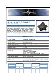
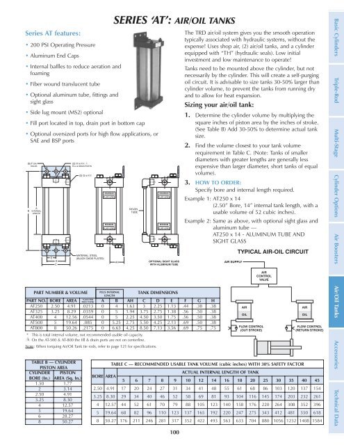
Series AT features:<br />
• 200 PSI Operat<strong>in</strong>g Pressure<br />
• Alum<strong>in</strong>um End Caps<br />
• Internal baffles to reduce aeration and<br />
foam<strong>in</strong>g<br />
• Fiber wound translucent tube<br />
• Optional alum<strong>in</strong>um tube, fitt<strong>in</strong>gs and<br />
sight glass<br />
• Side lug mount (MS2) optional<br />
• Fill port located <strong>in</strong> top, dra<strong>in</strong> port <strong>in</strong> bottom cap<br />
• Optional oversized ports for high flow applications, or<br />
SAE and BSP ports<br />
SERIES ‘AT’: AIR/OIL TANKS<br />
PART NUMBER & VOLUME PLUS INTERNAL TANK DIMENSIONS<br />
LENGTH<br />
PART NO. BORE AREA *GALS PER<br />
INCH TANK A B AH C D E F G H<br />
AT250 2.50 4.91 .0213 0 4 1.63 3 2.25 1.13 .44 .38 .38<br />
AT325 3.25 8.29 .0359 0 5 1.94 3.75 2.75 1.38 .56 .50 .38<br />
AT400 4 12.56 .0544 0 5 2.25 4.50 3.50 1.75 .56 .50 .38<br />
AT500 5 19.64 .085 0 5.25 2.75 5.50 4.25 2.13 .69 .50 .38<br />
AT800 8 50.26 .2175 0 6.63 4.25 8.50 7.13 3.56 .69 .75 .75<br />
* This is total <strong>in</strong>ternal volume, not recommended usable oil capacity.<br />
On the AT-500 & AT-800 the fill & dra<strong>in</strong> ports <strong>are</strong> not on centerl<strong>in</strong>e.<br />
Note: When torqu<strong>in</strong>g Air/Oil Tank tie rods, refer to page 121 for specifications.<br />
TABLE B — CYLINDER<br />
PISTON AREA<br />
CYLINDER PISTON<br />
BORE (In.) AREA (Sq. In.)<br />
1.50 1.77<br />
2 3.14<br />
2.50 4.91<br />
3.25 8.30<br />
4 12.57<br />
5 19.64<br />
6 28.27<br />
8 50.27<br />
BORE AREA<br />
100<br />
<strong>The</strong> TRD air/oil system gives you the smooth operation<br />
typic<strong>all</strong>y associated with hydraulic systems, without the<br />
expense! Uses shop air, (2) air/oil tanks, and a cyl<strong>in</strong>der<br />
equipped with “TH” (hydraulic seals). Low <strong>in</strong>itial<br />
<strong>in</strong>vestment and low ma<strong>in</strong>tenance to operate!<br />
Tanks need to be mounted above the cyl<strong>in</strong>der, but not<br />
necessarily by the cyl<strong>in</strong>der. This will create a self-purg<strong>in</strong>g<br />
oil circuit. It is advisable to size tanks 30-50% larger than<br />
cyl<strong>in</strong>der volume, to prevent the tanks from runn<strong>in</strong>g dry<br />
and to <strong>all</strong>ow for heat expansion.<br />
Siz<strong>in</strong>g your air/oil tank:<br />
1. Determ<strong>in</strong>e the cyl<strong>in</strong>der volume by multiply<strong>in</strong>g the<br />
squ<strong>are</strong> <strong>in</strong>ches of piston <strong>are</strong>a by the <strong>in</strong>ches of stroke.<br />
(See Table B) Add 30-50% to determ<strong>in</strong>e actual tank<br />
size.<br />
2. F<strong>in</strong>d the volume closest to your tank volume<br />
requirement <strong>in</strong> Table C. (Note: Tanks of sm<strong>all</strong>er<br />
diameters with greater lengths <strong>are</strong> gener<strong>all</strong>y less<br />
expensive than larger diameter, short tanks of equal<br />
volume).<br />
3. HOW TO ORDER:<br />
Specify bore and <strong>in</strong>ternal length required.<br />
Example 1: AT250 x 14<br />
(2.50” Bore, 14” <strong>in</strong>ternal tank length, with a<br />
usable volume of 52 cubic <strong>in</strong>ches).<br />
Example 2: Same as above, with optional sight glass and<br />
alum<strong>in</strong>um tube —<br />
AT250 x 14 - ALUMINUM TUBE AND<br />
SIGHT GLASS<br />
TABLE C — RECOMMENDED USABLE TANK VOLUME (cubic <strong>in</strong>ches) WITH 30% SAFETY FACTOR<br />
ACTUAL INTERNAL LENGTH OF TANK<br />
5 6 7 8 9 10 12 14 16 18 20 25 30 35 40 45<br />
2.50 4.91 17 20 24 27 31 34 41 48 55 61 68 86 103 120 137 154<br />
3.25 8.30 29 34 40 46 52 58 69 81 93 104 116 145 174 203 232 261<br />
4 12.57 44 52 61 70 79 88 105 123 140 158 176 220 264 308 352 396<br />
5 19.64 68 82 96 110 123 137 165 192 220 247 275 343 412 481 550 618<br />
8 50.27 176 211 246 281 317 352 422 493 563 633 704 880 1056 1232 1408 1584<br />
Basic Cyl<strong>in</strong>ders Triple-Rod Multi-Stage Cyl<strong>in</strong>der Options Air Boosters Air/Oil Tanks Accessories Technical Data